CN115429322A - TCCS probe fixing device - Google Patents
TCCS probe fixing device Download PDFInfo
- Publication number
- CN115429322A CN115429322A CN202211076530.5A CN202211076530A CN115429322A CN 115429322 A CN115429322 A CN 115429322A CN 202211076530 A CN202211076530 A CN 202211076530A CN 115429322 A CN115429322 A CN 115429322A
- Authority
- CN
- China
- Prior art keywords
- plate
- arc
- fixed
- base
- shaped
- Prior art date
- Legal status (The legal status is an assumption and is not a legal conclusion. Google has not performed a legal analysis and makes no representation as to the accuracy of the status listed.)
- Withdrawn
Links
Images


Classifications
-
- A—HUMAN NECESSITIES
- A61—MEDICAL OR VETERINARY SCIENCE; HYGIENE
- A61B—DIAGNOSIS; SURGERY; IDENTIFICATION
- A61B8/00—Diagnosis using ultrasonic, sonic or infrasonic waves
- A61B8/06—Measuring blood flow
-
- A—HUMAN NECESSITIES
- A61—MEDICAL OR VETERINARY SCIENCE; HYGIENE
- A61B—DIAGNOSIS; SURGERY; IDENTIFICATION
- A61B8/00—Diagnosis using ultrasonic, sonic or infrasonic waves
- A61B8/40—Positioning of patients, e.g. means for holding or immobilising parts of the patient's body
-
- A—HUMAN NECESSITIES
- A61—MEDICAL OR VETERINARY SCIENCE; HYGIENE
- A61B—DIAGNOSIS; SURGERY; IDENTIFICATION
- A61B8/00—Diagnosis using ultrasonic, sonic or infrasonic waves
- A61B8/42—Details of probe positioning or probe attachment to the patient
- A61B8/4209—Details of probe positioning or probe attachment to the patient by using holders, e.g. positioning frames
- A61B8/4218—Details of probe positioning or probe attachment to the patient by using holders, e.g. positioning frames characterised by articulated arms
-
- A—HUMAN NECESSITIES
- A61—MEDICAL OR VETERINARY SCIENCE; HYGIENE
- A61B—DIAGNOSIS; SURGERY; IDENTIFICATION
- A61B8/00—Diagnosis using ultrasonic, sonic or infrasonic waves
- A61B8/48—Diagnostic techniques
- A61B8/488—Diagnostic techniques involving Doppler signals
Landscapes
- Health & Medical Sciences (AREA)
- Life Sciences & Earth Sciences (AREA)
- Biomedical Technology (AREA)
- Biophysics (AREA)
- Nuclear Medicine, Radiotherapy & Molecular Imaging (AREA)
- Pathology (AREA)
- Radiology & Medical Imaging (AREA)
- Engineering & Computer Science (AREA)
- Physics & Mathematics (AREA)
- Heart & Thoracic Surgery (AREA)
- Medical Informatics (AREA)
- Molecular Biology (AREA)
- Surgery (AREA)
- Animal Behavior & Ethology (AREA)
- General Health & Medical Sciences (AREA)
- Public Health (AREA)
- Veterinary Medicine (AREA)
- Hematology (AREA)
- Measuring Leads Or Probes (AREA)
Abstract
Description
技术领域technical field
本发明涉及医疗器械领域,具体的涉及TCCS探头固定装置。The invention relates to the field of medical instruments, in particular to a TCCS probe fixing device.
背景技术Background technique
脑血流调节的评价对于颅脑手术和患者治疗效果的预测具有重要的临床应用价值,但在此过程中,需要保证监测的是同一根血管,不能出现监测探头位置的偏移。目前TCD脑血流调节固定装置使用的比较广泛,但是TCCS因各种原因目前尚无脑血流调节固定装置,相对于TCD的探头,TCCS的探头较大,但是其可以实时了解监测的是哪根血管、彩色多普勒情况、监测位置有无变化等,给临床可以提供更多的信息。The evaluation of cerebral blood flow regulation has important clinical application value for the prediction of craniocerebral surgery and patient treatment effect, but in this process, it is necessary to ensure that the same blood vessel is monitored, and the position of the monitoring probe cannot be shifted. At present, the TCD cerebral blood flow adjustment fixation device is widely used, but TCCS has no cerebral blood flow adjustment fixation device due to various reasons. Compared with the TCD probe, the TCCS probe is larger, but it can know in real time what is being monitored. Root vessels, color Doppler status, monitoring location changes, etc., can provide more clinical information.
发明内容Contents of the invention
针对现有技术中的问题,本发明提供了TCCS探头固定装置。Aiming at the problems in the prior art, the invention provides a TCCS probe fixing device.
本发明解决其技术问题所采用的技术方案是:TCCS探头固定装置,包括头颅固定组件、位于头颅固定组件一侧且可拆卸设于其上的机械臂、设于机械臂上的TCCS探头固定组件、设于机械臂上且用于调节TCCS探头角度的调节组件;所述头颅固定组件包括第一弧形板及与第一弧形板对称设置的第二弧形板、位于第一弧形板和第二弧形板中间的第三弧形板、一端固定设于第一弧形板上且另一端可移动插入第三弧形板上的第一弹力弧板、一端固定设于第二弧形板上且另一端可移动插入第三弧形板上的第二弹力弧板、设于第三弧形板内侧的适配元件、固定设于第一弹力弧板上的第一基座、固定设于第二弹力弧板上的第二基座、两端分别设于第一基座和第二基座上的辅助元件、用于驱动第一弹力弧板和第二弹力弧板位于第三弧形板内移动且用于驱动辅助元件收紧的驱动元件,所述驱动元件位于第三弧形板外侧。The technical solution adopted by the present invention to solve its technical problems is: TCCS probe fixing device, comprising a skull fixation assembly, a mechanical arm located on one side of the skull fixation assembly and detachably arranged thereon, and a TCCS probe fixing assembly arranged on the mechanical arm , the adjustment component that is arranged on the mechanical arm and is used to adjust the angle of the TCCS probe; the head fixation component includes a first arc-shaped plate and a second arc-shaped plate symmetrically arranged with the first arc-shaped plate, located on the first arc-shaped plate The third arc-shaped plate in the middle of the second arc-shaped plate, one end is fixed on the first arc-shaped plate and the other end is movably inserted into the first elastic arc plate on the third arc-shaped plate, and one end is fixed on the second arc-shaped plate shaped plate and the other end can be movably inserted into the second elastic arc plate on the third arc-shaped plate, the adapter element arranged inside the third arc-shaped plate, the first base fixed on the first elastic arc plate, The second base fixed on the second elastic arc plate, the auxiliary elements respectively arranged on the first base and the second base at both ends, are used to drive the first elastic arc plate and the second elastic arc plate to be positioned on the second elastic arc plate The driving element that moves inside the three arc-shaped plate and is used to drive the auxiliary element to tighten, the driving element is located outside the third arc-shaped plate.
具体的,所述适配元件包括第三弹力弧板、设于第三弹力弧板上的第一滑槽、固定设于第三弹力弧板中间处的第一固定块、与第一滑槽垂直且设于固定块上的第二滑槽、固定设于第一固定块中间处的第二固定块、位于第二固定块上下两侧且可移动设于第二滑槽上的第三滑块和第四滑块、一端转动设于第三弧形板上且另一端转动设于第三滑块上的第五弧形转板、一端转动设于第三弧形板上且另一端转动设于第四滑块上的第六弧形转板、两端分别固定设于第三滑块和第二固定块上的第三弹簧、两端分别固定设于第四滑块和第二固定块上的第四弹簧,所述第五弧形转板与所述第六弧形转板对称设置。Specifically, the adapter element includes a third elastic arc plate, a first chute arranged on the third elastic arc plate, a first fixing block fixed in the middle of the third elastic arc plate, and the first chute The second chute is vertical and set on the fixed block, the second fixed block is fixed in the middle of the first fixed block, the third slide is located on the upper and lower sides of the second fixed block and can be moved on the second chute block and the fourth slider, one end is rotated on the third arc-shaped plate and the other end is rotated on the fifth arc-shaped rotating plate on the third slider, one end is rotated on the third arc-shaped plate and the other end is rotated The sixth arc-shaped rotating plate on the fourth slider, the third spring fixed on the third slider and the second fixed block at both ends, respectively fixed on the fourth slider and the second fixed block at both ends The fourth spring on the block, the fifth arc-shaped rotating plate and the sixth arc-shaped rotating plate are arranged symmetrically.
具体的,所述适配元件还包括位于第一固定块两侧且可移动设于第一滑槽上的第一滑块和第二滑块、两端分别固定设于第一滑块和第三弹力弧板上的第一弹簧、两端分别固定设于第二滑块和第三弹力弧板上的第二弹簧、一端转动设于第一固定块上的第一弧形转板及与其对称设置的第二弧形转板、一端转动设于第一弧形转板另一端上且另一端转动设于第一滑块上的第三弧形转板、一端转动设于第二弧形转板另一端上且另一端转动设于第二滑块上的第四弧形转板。Specifically, the adapter element also includes a first slider and a second slider which are located on both sides of the first fixed block and are movably arranged on the first sliding groove, and the two ends are respectively fixed on the first slider and the second slider. The first spring on the three elastic arc plates, the two ends are respectively fixed on the second spring on the second slide block and the third elastic arc plate, and the first arc-shaped rotating plate on the first fixed block is rotated at one end and connected with it. Symmetrically arranged second arc-shaped rotating plate, one end is rotated on the other end of the first arc-shaped rotating plate and the other end is rotated on the third arc-shaped rotating plate on the first slider, and one end is rotated on the second arc-shaped rotating plate On the other end of the rotating plate and the other end rotates the fourth arc-shaped rotating plate arranged on the second slide block.
具体的,所述辅助元件包括一端固定设于第一基座上的第一空心管、一端固定设于第二基座上的第二空心管、两端分别可移动插入第一空心管和第二空心管内的第四弹力弧板、位于第一空心管内且两端分别固定设于第四弹力弧板和第一基座上的第五弹簧、位于第二空心管内且两端分别固定设于第四弹力弧板和第二基座上的第六弹簧。Specifically, the auxiliary element includes a first hollow tube with one end fixed on the first base, a second hollow tube with one end fixed on the second base, and two ends that are respectively movably inserted into the first hollow tube and the second hollow tube. The fourth elastic arc plate in the second hollow tube, the fifth spring located in the first hollow tube and fixed at both ends on the fourth elastic arc plate and the first base, is located in the second hollow tube and fixed at both ends respectively The sixth spring on the fourth elastic arc plate and the second base.
具体的,所述驱动元件包括固定设于第三弧形板中间处的固定盘、贯穿且转动设于固定盘上的绕线辊、固定套设于绕线辊一端上的棘轮、可移动设于固定盘上的移动杆、与棘轮配合且固定设于移动杆一端上的卡板、套设于移动杆上且两端分别固定设于卡板和固定盘上的第七弹簧、穿设于第一基座且两端分别固定设于第四弹力弧板一端和绕线辊上的第一拉绳、穿设于第二基座且两端分别固定设于第四弹力弧板另一端和绕线辊上的第二拉绳。Specifically, the drive element includes a fixed disk fixed in the middle of the third arc-shaped plate, a winding roller that penetrates and rotates on the fixed disk, a ratchet wheel that is fixedly sleeved on one end of the winding roller, and a movable device. The moving rod on the fixed plate, the clamping plate that cooperates with the ratchet and is fixed on one end of the moving rod, the seventh spring that is sleeved on the moving rod and fixed on the clamping plate and the fixed plate at both ends, and penetrates the The first base and the two ends are respectively fixed on one end of the fourth elastic arc plate and the first pull cord on the winding roller, which is passed through the second base and the two ends are respectively fixed on the other end of the fourth elastic arc plate and the first pull cord on the winding roller. Second drawstring on the winding roller.
具体的,所述驱动元件还包括设于绕线辊内的第一腔室、设于固定盘内的第二腔室、设于固定盘上的环形开槽、设于绕线辊上的多个通孔、一端可移动插入第一腔室内的推杆、位于第一腔室内且两端分别固定设于绕线辊和推杆上的第八弹簧、转动设于推杆另一端上的转盘、一端可移动插入固定盘内的从动杆、两端分别固定设于移动杆和从动杆上的连接板。Specifically, the driving element also includes a first chamber arranged in the winding roller, a second chamber arranged in the fixed disk, an annular groove arranged on the fixed disk, and a plurality of holes arranged on the winding roller. a through hole, one end can be movably inserted into the push rod in the first chamber, the eighth spring is located in the first chamber and its two ends are respectively fixed on the winding roller and the push rod, and the rotating disk is arranged on the other end of the push rod 1. One end can be movably inserted into the driven rod in the fixed disk, and the two ends are respectively fixed on the connecting plate arranged on the moving rod and the driven rod.
具体的,所述机械臂包括可拆卸固定设于第一基座上的第三空心管、一端可移动设于第三空心管内的第四空心管、固定设于第四空心管内的内螺纹块、固定设于第四空心管另一端上的第三基座、一端转动设于第一基座上且另一端贯穿可移动设于第三基座上的螺杆、位于第三空心管内且两端分别固定设于第四空心管和第一基座上的第九弹簧、可移动设于第三基座上的移动架、等距间隔设于移动架上的多个弧形凹槽、可移动设于第三基座上的顶杆、转动设于顶杆一端上的滚珠、套设于顶杆上且两端分别固定设于第三基座和顶杆另一端上的第十弹簧,所述螺杆与内螺纹块配合。Specifically, the mechanical arm includes a third hollow tube detachably fixed on the first base, a fourth hollow tube with one end movably set in the third hollow tube, and an internal thread block fixed in the fourth hollow tube. , the third base fixed on the other end of the fourth hollow tube, one end rotated on the first base and the other end runs through the screw rod movably set on the third base, located in the third hollow tube and the two ends The ninth spring respectively fixed on the fourth hollow tube and the first base, the mobile frame which is movable on the third base, the plurality of arc-shaped grooves which are equidistantly arranged on the mobile frame, and the movable The ejector rod arranged on the third base, the rolling ball arranged on one end of the ejector rod, the tenth spring sleeved on the ejector rod and fixed on the third base and the other end of the ejector rod at both ends, the Said screw rod cooperates with internal thread block.
具体的,所述机械臂还包括固定设于移动架上的导向盘、固定设于导向盘中心处的固定轴、固定套设于固定轴上的齿轮、转动套设于齿轮上的旋转块、可移动设于旋转块上的第一卡件及第二卡件、两端分别固定设于第一卡件和旋转块上的第十一弹簧、两端分别固定设于第二卡件和旋转块上的第十二弹簧、固定设于旋转块上的旋转架、设于旋转架上的弧形面,所述弧形面与所述导向盘接触,旋转架转动过程中弧形面沿着导向盘移动。Specifically, the mechanical arm also includes a guide plate fixed on the moving frame, a fixed shaft fixed at the center of the guide plate, a gear fixedly sleeved on the fixed shaft, a rotating block sleeved on the gear, The first clip and the second clip on the rotating block can be moved, the two ends of the eleventh spring are respectively fixed on the first clip and the rotating block, and the two ends are respectively fixed on the second clip and the rotating block. The twelfth spring on the block, the rotating frame fixed on the rotating block, and the arc-shaped surface arranged on the rotating frame, the arc-shaped surface is in contact with the guide plate, and the arc-shaped surface is along the The guide disc moves.
所述调节组件包括转动设于旋转架上的转杆、套设于转杆上且固定设于旋转架上的刻度盘、与刻度盘同轴心且固定设于刻度盘上的固定环、等距环形分布设于固定环上的多个卡槽、等距间隔且一端固定设于转杆上的多个弹簧伸缩杆、设于弹簧伸缩杆上的第一卡柱、贯穿可移动设于弹簧伸缩杆上的弧形圆杆、分别设于弧形圆杆两端的两个第二卡柱、固定设于第一卡柱上的指针、沿转杆方向设置且可移动设于其上的尺板、固定设于尺板上的导轨、设于转杆上用于对尺板进行固定的螺丝。The adjustment assembly includes a rotating rod mounted on the rotating frame, a dial sleeved on the rotating rod and fixed on the rotating frame, a fixed ring coaxial with the dial and fixed on the dial, etc. A plurality of card slots arranged in a ring on the fixed ring, equidistant intervals and a plurality of spring telescopic rods fixed on the rotating rod at one end, a first clamping column arranged on the spring telescopic rod, and a penetrating movable rod arranged on the spring The arc-shaped round rod on the telescopic rod, the two second clamping columns respectively arranged at the two ends of the arc-shaped round rod, the pointer fixed on the first clamping column, the ruler arranged along the direction of the rotating rod and movable on it Plate, the guide rail fixed on the ruler plate, and the screw used to fix the ruler plate on the rotating rod.
所述探头固定组件包括转动设于转杆上的第四基座、两端分别固定设于转杆和第四基座上的扭簧、一端可移动设于导轨上且另一端转动设于第四基座一端上的滑杆、固定设于第四基座上的气垫、固定设于第四基座上的两个子魔术贴、分别与两个子魔术贴配合且固定设于第四基座上的两个母魔术贴。The probe fixing assembly includes a fourth base that is rotated on the rotating rod, a torsion spring that is fixed at both ends on the rotating rod and the fourth base, one end is movable on the guide rail and the other end is rotated on the fourth base. The slide rod on one end of the four bases, the air cushion fixed on the fourth base, the two sub-velcros fixed on the fourth base, respectively matched with the two sub-velcros and fixed on the fourth base of two female Velcro.
本发明的有益效果是:The beneficial effects of the present invention are:
(1)首先把TCCS探头固定在TCCS探头固定组件上,再把头颅固定组件带在头上,使第一弧形板和第二弧形板及第三弧形板能够初步完成与头颅的固定工作,通过驱动元件驱动第一弹力弧板和第二弹力弧板相对移动,即使第一弹力弧板和第二弹力弧板收紧,对患者头部进行固定,通过适配元件控制其收紧的力度,所述适配元件位于患者的额头处,所述第一弧形板和第二弧形板分别位于患者两个耳朵后上方,通过机械臂把TCCS探头位于需要监测处,再通过调节组件能够对该监测处进行180°任一角度调节,通过适配元件可避免第一弹力弧板和第二弹力弧板收的太紧,对患者头部造成不适,同时能够更好的适配额头处的弧度,能够根据患者头部的大小进行自动适配,且根据患者额头的大小进行自动适配,使与患者头部固定的更为牢固,且不会对患者造成不适感,避免TCCS的探头监测过程中移动位置,通过TCCS的探头对患者的监测,可以实时了解监测的是哪根血管、彩色多普勒情况、监测位置有无变化,给临床可以提供更多的信息。(1) First, fix the TCCS probe on the TCCS probe fixing component, and then put the skull fixation component on the head, so that the first arc-shaped plate, the second arc-shaped plate and the third arc-shaped plate can be initially fixed to the skull Work, drive the first elastic arc plate and the second elastic arc plate to move relatively through the driving element, even if the first elastic arc plate and the second elastic arc plate are tightened, the patient’s head is fixed, and the tightening is controlled by the adapter element strength, the adapting element is located on the forehead of the patient, the first arc-shaped plate and the second arc-shaped plate are respectively located behind and above the patient’s two ears, and the TCCS probe is positioned at the place to be monitored by the mechanical arm, and then adjusted The assembly can adjust any angle of 180° at the monitoring point, and the adapter element can prevent the first elastic arc plate and the second elastic arc plate from being too tight, causing discomfort to the patient’s head, and at the same time can better fit The curvature of the forehead can be automatically adapted according to the size of the patient's head, and can be automatically adapted according to the size of the patient's forehead, so that it can be fixed more firmly with the patient's head without causing discomfort to the patient and avoiding TCCS The position of the probe is moved during the monitoring process. Through the monitoring of the patient by the probe of the TCCS, it is possible to know in real time which blood vessel is being monitored, the color Doppler status, and whether the monitoring position has changed, and more information can be provided to the clinic.
(2)通过转动绕线辊,使第一拉绳和第二拉绳绕在绕线辊上,第一拉绳拉动第四弹力弧板一端向第一空心管内移动,第二拉绳拉动第四弹力弧板另一端向第二空心管内移动,使第四弹力弧板收紧,对患者头部进行固定,当第四弹力弧板收紧完成后,继续驱动绕线辊转动,使第一基座和第二基座向第三弧形板方向移动,使第一弹力弧板和第二弹力弧板相对移动,对患者头部进行固定,通过移动杆和卡板及第七弹簧设置,使棘轮单向转动,即使绕线辊单向转动,第一弹力弧板和第二弹力弧板完成收紧后可进行固定;第三弹力弧板与患者额头处的皮肤接触,受力到挤压力后,使第一弧形转板至第六弧形转板转动,第五弧形转板和第六弧形转板及第三弹簧和第四弹簧设置,能够改变第三弹力弧板竖直方向角度的调节,根据患者额头处的曲线进行自动适配,通过第一弧形转板至第四弧形转板和第一弹簧及第二弹簧设置,能够改变第三弹力弧板水平方向角度的调节,根据患者额头处的曲线进行自动适配,可对第一弹力弧板至第三弹力弧板同时完成固定,固定操作简单快捷;通过上述设置能够使第三弹力弧板更好的变形,且适配患者的额头处的曲线,使第三弹力弧板更好的与患者皮肤接触,通过上述设置能够减少与患者头部的接触,使固定后透气性好,大大降低了患者的不适感。(2) By rotating the winding roller, the first pull rope and the second pull rope are wound on the winding roller, the first pull rope pulls one end of the fourth elastic arc plate to move into the first hollow tube, and the second pull rope pulls the second pull rope The other end of the four elastic arc plates moves into the second hollow tube to tighten the fourth elastic arc plate and fix the patient’s head. After the fourth elastic arc plate is tightened, continue to drive the winding roller to rotate to make the first The base and the second base move toward the third arc-shaped plate, so that the first elastic arc plate and the second elastic arc plate move relatively, and fix the patient's head. Make the ratchet rotate in one direction, even if the winding roller rotates in one direction, the first elastic arc plate and the second elastic arc plate can be fixed after being tightened; After pressing, the first to sixth arc-shaped rotating plates are rotated, the fifth and sixth arc-shaped rotating plates and the third and fourth springs are set, and the third elastic arcing plate can be changed The adjustment of the vertical angle is automatically adapted according to the curve of the patient's forehead, and the level of the third elastic arc plate can be changed by setting the first to fourth arc-shaped rotating plates and the first and second springs The adjustment of the direction and angle is automatically adapted according to the curve of the patient's forehead, and the first elastic arc plate to the third elastic arc plate can be fixed at the same time, and the fixing operation is simple and fast; through the above settings, the third elastic arc plate can be better deformation, and adapt to the curve of the patient's forehead, so that the third elastic arc plate can better contact the patient's skin. Through the above settings, the contact with the patient's head can be reduced, and the air permeability is good after fixation, which greatly reduces the patient's discomfort.
(3)把头颅固定组件从患者的头颅上取下来时,只需推动顶杆,使顶杆向绕线辊内移动,使第二腔室内的空气通过通孔进入第一腔室内,第一腔室内的压强变大,使从动杆向固定盘外移动,使连接板和移动杆一起移动使卡板与棘轮完全脱离,第一弹力弧板和第二弹力弧板进行自动复位,使棘轮可以进行反向转动,转盘设置能够使推杆同绕线管一起反向转动,取下来方便快捷,通过第八弹簧能够对推杆进行复位,通过环形开槽及通孔设置能够使第一腔室与第二腔室始终保持连通,使绕线管转动位于固定盘上。(3) When the head fixation assembly is taken off from the patient's skull, it is only necessary to push the push rod to move the push rod in the winding roller, so that the air in the second chamber enters the first chamber through the through hole, and the first The pressure in the chamber increases, so that the driven rod moves out of the fixed plate, and the connecting plate and the moving rod move together to completely separate the clamping plate from the ratchet, and the first elastic arc plate and the second elastic arc plate are automatically reset, so that the ratchet Reverse rotation is possible, the turntable setting can make the push rod and the bobbin rotate in reverse together, it is convenient and quick to remove, the push rod can be reset by the eighth spring, and the first chamber can be made The chamber is always in communication with the second chamber, so that the bobbin is rotatably located on the fixed disk.
(4)所述螺杆与内螺纹块配合,从而转动螺杆使第四空心管沿着第三空心管方向移动,使第三基座远离或靠近第一基座,能够使TCCS探头靠近患者或远离患者,即对TCCS探头远近距离进行调节,通过第九弹簧能够对第四空心管产生推力,螺杆转动后即可完成固定,避免螺杆意外转动,通过移动移动架,能够使TCCS探头水平移动,即对TCCS探头水平位置进行调节,通过顶杆和第十弹簧设置能够使顶杆上的滚珠位于弧形凹槽内,从而完成对移动架的固定,当移动架移动力大于第十弹簧的弹力时,使移动架可以进行移动,通过转动旋转架,可对TCCS探头进行竖直方向调节,使TCCS探头处于监测处,通过第一卡件和第二卡件及第十一弹簧和第十二弹簧能够对齿轮进行固定,旋转架的转动力大于第十一弹簧和第十二弹簧弹力之和时,使旋转架转动,小于二者之和时对旋转架进行固定,通过调节组件对TCCS探头的角度进行调节,最终使TCCS探头更好的完成对患者的监测工作,综上所述对TCCS探头位置调节的范围大,能够适应更多的患者使用,通用性强;通过弧形面设置使旋转架与导向盘接触,即旋转架转动过程中弧形面沿着导向盘表面移动,从而使旋转架转动过程中更稳定,。(4) The screw rod cooperates with the internal thread block, thereby turning the screw rod to move the fourth hollow tube along the direction of the third hollow tube, so that the third base is away from or close to the first base, so that the TCCS probe can be close to or away from the patient The patient adjusts the distance of the TCCS probe. The ninth spring can generate a thrust on the fourth hollow tube. After the screw rotates, the fixation can be completed to avoid accidental rotation of the screw. By moving the moving frame, the TCCS probe can be moved horizontally, that is, To adjust the horizontal position of the TCCS probe, the ball on the ejector rod can be located in the arc-shaped groove through the setting of the ejector rod and the tenth spring, so as to complete the fixing of the mobile frame. When the moving force of the mobile frame is greater than the elastic force of the tenth spring , so that the mobile frame can be moved, by rotating the rotating frame, the TCCS probe can be adjusted vertically, so that the TCCS probe is at the monitoring position, through the first and second clamps and the eleventh spring and the twelfth spring The gear can be fixed. When the rotating force of the rotating frame is greater than the sum of the elastic forces of the eleventh spring and the twelfth spring, the rotating frame is rotated. When it is less than the sum of the two, the rotating frame is fixed. The angle is adjusted, and finally the TCCS probe can better complete the monitoring work of the patient. In summary, the position adjustment range of the TCCS probe is large, which can adapt to more patients and has strong versatility; through the arc surface setting, the rotation The frame is in contact with the guide plate, that is, the arc surface moves along the surface of the guide plate during the rotation of the rotating frame, so that the rotating frame is more stable during rotation.
(5)把TCCS探头放在第四基座上,通过两个母魔术贴对其完成捆绑,并与两个子魔术贴配合,通过气垫设置能够使第四基座更好的适配TCCS探头的表面曲线,对TCCS探头固定的更为牢固;通过移动尺板,使导轨一起移动,使滑杆移动,使第四基座转动,最终使TCCS探头转动,再通过转动转杆,可对调好角度后的TCCS探头进行360°角度进行调节,通过螺丝对尺板进行固定,转杆的转动力大于弹簧伸缩杆的弹力时,使转杆转动,即通过弹簧伸缩杆及其上的第一卡柱与固定环上的卡槽配合,能够对转杆进行固定,通过弧形圆杆及其上的两个第二卡柱设置,能够使转杆固定的更为牢固,通过上述设置能够对TCCS探头角度的调节范围大,当第四基座与转杆平行时,通过扭簧设置能够对第四基座起到扭转力,便于第四基座的角度调节;通过指针与刻度盘配合设置能够更好的确定转杆转动的角度,可进行精密角度调节,转杆带动弹簧伸缩杆转动时,弧形圆杆可位于弹簧伸缩杆上进行适当的移动,以适应弹簧伸缩杆的转动,最终两个第二卡柱能够还能够位于卡槽内,通过第一卡柱和两个第二卡柱对转杆进行固定,使固定的更为牢固。(5) Put the TCCS probe on the fourth base, bind it through two female Velcro, and cooperate with the two sub-Velcro, the fourth base can be better adapted to the TCCS probe through the air cushion setting The surface curve is more firmly fixed to the TCCS probe; by moving the scale plate, the guide rail moves together, the slider moves, the fourth base rotates, and finally the TCCS probe rotates, and then the angle can be adjusted by turning the rotating rod The last TCCS probe is adjusted at a 360° angle, and the scale plate is fixed by screws. When the rotating force of the rotating rod is greater than the elastic force of the spring telescopic rod, the rotating rod is rotated, that is, through the spring telescopic rod and the first clamping column on it. Cooperate with the card slot on the fixing ring to fix the rotating rod. Through the setting of the arc-shaped round rod and the two second clamping posts on it, the rotating rod can be fixed more firmly. Through the above settings, the TCCS probe can be fixed The angle adjustment range is large. When the fourth base is parallel to the rotating rod, the torsion spring setting can exert a torsion force on the fourth base, which is convenient for the angle adjustment of the fourth base; It is good to determine the rotation angle of the rotating rod, and the precise angle adjustment can be performed. When the rotating rod drives the spring telescopic rod to rotate, the arc-shaped round rod can be located on the spring telescopic rod for proper movement to adapt to the rotation of the spring telescopic rod. Finally, the two The second clamping column can also be located in the clamping groove, and the rotating rod is fixed by the first clamping column and the two second clamping columns, so that the fixing is more firm.
附图说明Description of drawings
下面结合附图和实施例对本发明进一步说明。The present invention will be further described below in conjunction with the accompanying drawings and embodiments.
图1为本发明的结构示意图;Fig. 1 is a structural representation of the present invention;
图2为本发明的侧面示意图;Fig. 2 is a schematic side view of the present invention;
图3为图2中的D处放大图;Figure 3 is an enlarged view at D in Figure 2;
图4为图2中的E处放大图;Figure 4 is an enlarged view of the E place in Figure 2;
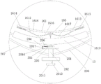
图5为本发明的正面示意图;Figure 5 is a schematic front view of the present invention;
图6为图5中的A-A线的部分剖视图;Fig. 6 is a partial sectional view of line A-A in Fig. 5;
图7为图6中的B-B线的结构剖视图一;Fig. 7 is a structural sectional view one of the B-B line in Fig. 6;
图8为图6中的B-B线的结构剖视图二;Fig. 8 is the second structural cross-sectional view of the B-B line in Fig. 6;
图9为图5中的C-C线的剖视图;Fig. 9 is the sectional view of C-C line among Fig. 5;
图10为图9中的A处放大图;Figure 10 is an enlarged view of A in Figure 9;
图11为图9中的D-D线的部分剖视图;Fig. 11 is a partial sectional view of the line D-D in Fig. 9;
图12为机械臂的结构示意图;Fig. 12 is the structural representation of mechanical arm;
图13为图12中的B处放大图;Figure 13 is an enlarged view at B in Figure 12;
图14为图12中的C处放大图;Figure 14 is an enlarged view at C in Figure 12;
图15为图12中的F处放大图。FIG. 15 is an enlarged view of F in FIG. 12 .
具体实施方式detailed description
为了使本发明实现的技术手段、创作特征、达成目的与功效易于明白了解,下面结合具体实施方式,进一步阐述本发明。In order to make the technical means, creative features, goals and effects achieved by the present invention easy to understand, the present invention will be further described below in conjunction with specific embodiments.
如图1-图15所示,本发明所述的TCCS探头固定装置,包括头颅固定组件1、位于头颅固定组件一侧且可拆卸设于其上的机械臂2、设于机械臂上的TCCS探头固定组件3、设于机械臂上且用于调节TCCS探头角度的调节组件4;所述头颅固定组件1包括第一弧形板11及与第一弧形板对称设置的第二弧形板12、位于第一弧形板和第二弧形板中间的第三弧形板13、一端固定设于第一弧形板上且另一端可移动插入第三弧形板上的第一弹力弧板14、一端固定设于第二弧形板上且另一端可移动插入第三弧形板上的第二弹力弧板15、设于第三弧形板内侧的适配元件16、固定设于第一弹力弧板上的第一基座17、固定设于第二弹力弧板上的第二基座18、两端分别设于第一基座和第二基座上的辅助元件19、用于驱动第一弹力弧板和第二弹力弧板位于第三弧形板内移动且用于驱动辅助元件收紧的驱动元件20,所述驱动元件位于第三弧形板外侧。As shown in Figures 1 to 15, the TCCS probe fixing device of the present invention includes a cranial fixation assembly 1, a mechanical arm 2 located on one side of the cranial fixation assembly and detachably arranged on it, and a TCCS on the mechanical arm. Probe fixing
具体的,所述适配元件16包括第三弹力弧板161、设于第三弹力弧板上的第一滑槽162、固定设于第三弹力弧板中间处的第一固定块163、与第一滑槽垂直且设于固定块上的第二滑槽164、固定设于第一固定块中间处的第二固定块165、位于第二固定块上下两侧且可移动设于第二滑槽上的第三滑块166和第四滑块167、一端转动设于第三弧形板上且另一端转动设于第三滑块上的第五弧形转板168、一端转动设于第三弧形板上且另一端转动设于第四滑块上的第六弧形转板169、两端分别固定设于第三滑块和第二固定块上的第三弹簧1610、两端分别固定设于第四滑块和第二固定块上的第四弹簧1611,所述第五弧形转板与所述第六弧形转板对称设置。Specifically, the
具体的,所述适配元件16还包括位于第一固定块两侧且可移动设于第一滑槽上的第一滑块1612和第二滑块1613、两端分别固定设于第一滑块和第三弹力弧板上的第一弹簧1614、两端分别固定设于第二滑块和第三弹力弧板上的第二弹簧1615、一端转动设于第一固定块上的第一弧形转板1616及与其对称设置的第二弧形转板1617、一端转动设于第一弧形转板另一端上且另一端转动设于第一滑块上的第三弧形转板1618、一端转动设于第二弧形转板另一端上且另一端转动设于第二滑块上的第四弧形转板1619。Specifically, the
具体的,所述辅助元件19包括一端固定设于第一基座上的第一空心管191、一端固定设于第二基座上的第二空心管192、两端分别可移动插入第一空心管和第二空心管内的第四弹力弧板193、位于第一空心管内且两端分别固定设于第四弹力弧板和第一基座上的第五弹簧194、位于第二空心管内且两端分别固定设于第四弹力弧板和第二基座上的第六弹簧195。Specifically, the
具体的,所述驱动元件20包括固定设于第三弧形板中间处的固定盘201、贯穿且转动设于固定盘上的绕线辊202、固定套设于绕线辊一端上的棘轮203、可移动设于固定盘上的移动杆204、与棘轮配合且固定设于移动杆一端上的卡板205、套设于移动杆上且两端分别固定设于卡板和固定盘上的第七弹簧206、穿设于第一基座且两端分别固定设于第四弹力弧板一端和绕线辊上的第一拉绳207、穿设于第二基座且两端分别固定设于第四弹力弧板另一端和绕线辊上的第二拉绳208。Specifically, the driving
具体的,所述驱动元件20还包括设于绕线辊内的第一腔室209、设于固定盘内的第二腔室2010、设于固定盘上的环形开槽2011、设于绕线辊上的多个通孔2012、一端可移动插入第一腔室内的推杆2013、位于第一腔室内且两端分别固定设于绕线辊和推杆上的第八弹簧2014、转动设于推杆另一端上的转盘2015、一端可移动插入固定盘内的从动杆2016、两端分别固定设于移动杆和从动杆上的连接板2017。Specifically, the driving
具体的,所述机械臂2包括可拆卸固定设于第一基座上的第三空心管21、一端可移动设于第三空心管内的第四空心管22、固定设于第四空心管内的内螺纹块23、固定设于第四空心管另一端上的第三基座24、一端转动设于第一基座上且另一端贯穿可移动设于第三基座上的螺杆25、位于第三空心管内且两端分别固定设于第四空心管和第一基座上的第九弹簧26、可移动设于第三基座上的移动架27、等距间隔设于移动架上的多个弧形凹槽28、可移动设于第三基座上的顶杆29、转动设于顶杆一端上的滚珠、套设于顶杆上且两端分别固定设于第三基座和顶杆另一端上的第十弹簧211,所述螺杆与内螺纹块配合。Specifically, the mechanical arm 2 includes a third
具体的,所述机械臂2还包括固定设于移动架上的导向盘212、固定设于导向盘中心处的固定轴213、固定套设于固定轴上的齿轮214、转动套设于齿轮上的旋转块215、可移动设于旋转块上的第一卡件216及第二卡件217、两端分别固定设于第一卡件和旋转块上的第十一弹簧218、两端分别固定设于第二卡件和旋转块上的第十二弹簧219、固定设于旋转块上的旋转架220、设于旋转架上的弧形面221,所述弧形面与所述导向盘接触,旋转架转动过程中弧形面沿着导向盘移动。Specifically, the mechanical arm 2 also includes a
所述调节组件4包括转动设于旋转架上的转杆41、套设于转杆上且固定设于旋转架上的刻度盘42、与刻度盘同轴心且固定设于刻度盘上的固定环43、等距环形分布设于固定环上的多个卡槽44、等距间隔且一端固定设于转杆上的多个弹簧伸缩杆45、设于弹簧伸缩杆上的第一卡柱46、贯穿可移动设于弹簧伸缩杆上的弧形圆杆47、分别设于弧形圆杆两端的两个第二卡柱48、固定设于第一卡柱上的指针49、沿转杆方向设置且可移动设于其上的尺板410、固定设于尺板上的导轨411、设于转杆上用于对尺板进行固定的螺丝412。The adjustment assembly 4 includes a
所述探头固定组件3包括转动设于转杆上的第四基座31、两端分别固定设于转杆和第四基座上的扭簧32、一端可移动设于导轨上且另一端转动设于第四基座一端上的滑杆33、固定设于第四基座上的气垫34、固定设于第四基座上的两个子魔术贴35、分别与两个子魔术贴配合且固定设于第四基座上的两个母魔术贴36。The
本发明在使用时,首先把TCCS探头固定在TCCS探头固定组件上,再把头颅固定组件带在头上,使第一弧形板和第二弧形板及第三弧形板能够初步完成与头颅的固定工作,通过驱动元件驱动第一弹力弧板和第二弹力弧板相对移动,即使第一弹力弧板和第二弹力弧板收紧,对患者头部进行固定,通过适配元件控制其收紧的力度,所述适配元件位于患者的额头处,所述第一弧形板和第二弧形板分别位于患者两个耳朵后上方,通过机械臂把TCCS探头位于需要监测处,再通过调节组件能够对该监测处进行180°任一角度调节;通过转动绕线辊,使第一拉绳和第二拉绳绕在绕线辊上,第一拉绳拉动第四弹力弧板一端向第一空心管内移动,第二拉绳拉动第四弹力弧板另一端向第二空心管内移动,使第四弹力弧板收紧,对患者头部进行固定,当第四弹力弧板收紧完成后,继续驱动绕线辊转动,使第一基座和第二基座向第三弧形板方向移动,使第一弹力弧板和第二弹力弧板相对移动,对患者头部进行固定,通过移动杆和卡板及第七弹簧设置,使棘轮单向转动,即使绕线辊单向转动,第一弹力弧板和第二弹力弧板完成收紧后可进行固定;第三弹力弧板与患者额头处的皮肤接触,受力到挤压力后,使第一弧形转板至第六弧形转板转动,第五弧形转板和第六弧形转板及第三弹簧和第四弹簧设置,能够改变第三弹力弧板竖直方向角度的调节,根据患者额头处的曲线进行自动适配,通过第一弧形转板至第四弧形转板和第一弹簧及第二弹簧设置,能够改变第三弹力弧板水平方向角度的调节,根据患者额头处的曲线进行自动适配;把头颅固定组件从患者的头颅上取下来时,只需推动顶杆,使顶杆向绕线辊内移动,使第二腔室内的空气通过通孔进入第一腔室内,第一腔室内的压强变大,使从动杆向固定盘外移动,使连接板和移动杆一起移动使卡板与棘轮完全脱离,第一弹力弧板和第二弹力弧板进行自动复位,使棘轮可以进行反向转动,转盘设置能够使推杆同绕线管一起反向转动;所述螺杆与内螺纹块配合,从而转动螺杆使第四空心管沿着第三空心管方向移动,使第三基座远离或靠近第一基座,能够使TCCS探头靠近患者或远离患者,即对TCCS探头远近距离进行调节,通过第九弹簧能够对第四空心管产生推力,螺杆转动后即可完成固定,避免螺杆意外转动,通过移动移动架,能够使TCCS探头水平移动,即对TCCS探头水平位置进行调节,通过顶杆和第十弹簧设置能够使顶杆上的滚珠位于弧形凹槽内,从而完成对移动架的固定,当移动架移动力大于第十弹簧的弹力时,使移动架可以进行移动,通过转动旋转架,可对TCCS探头进行竖直方向调节,使TCCS探头处于监测处,通过第一卡件和第二卡件及第十一弹簧和第十二弹簧能够对齿轮进行固定,旋转架的转动力大于第十一弹簧和第十二弹簧弹力之和时,使旋转架转动,小于二者之和时对旋转架进行固定,通过调节组件对TCCS探头的角度进行调节,最终使TCCS探头更好的完成对患者的监测工作;把TCCS探头放在第四基座上,通过两个母魔术贴对其完成捆绑,并与两个子魔术贴配合,通过气垫设置能够使第四基座更好的适配TCCS探头的表面曲线,对TCCS探头固定的更为牢固;通过移动尺板,使导轨一起移动,使滑杆移动,使第四基座转动,最终使TCCS探头转动,再通过转动转杆,可对调好角度后的TCCS探头进行360°角度进行调节,通过螺丝对尺板进行固定,转杆的转动力大于弹簧伸缩杆的弹力时,使转杆转动,即通过弹簧伸缩杆及其上的第一卡柱与固定环上的卡槽配合,能够对转杆进行固定,通过弧形圆杆及其上的两个第二卡柱设置,能够使转杆固定的更为牢固。When the present invention is in use, at first the TCCS probe is fixed on the TCCS probe fixing assembly, and then the skull fixing assembly is brought on the head, so that the first arc-shaped plate, the second arc-shaped plate and the third arc-shaped plate can be preliminarily completed. For the fixation of the head, drive the first elastic arc plate and the second elastic arc plate to move relative to each other through the driving element, even if the first elastic arc plate and the second elastic arc plate are tightened, the patient’s head is fixed, controlled by the adapter element For its tightening strength, the adapting element is located on the forehead of the patient, the first arc-shaped plate and the second arc-shaped plate are respectively located behind and above the two ears of the patient, and the TCCS probe is positioned at the place to be monitored through the mechanical arm. Then the monitoring part can be adjusted at any angle of 180° through the adjustment assembly; by rotating the winding roller, the first pull cord and the second pull cord are wound on the winding roller, and the first pull rope pulls the fourth elastic arc plate One end moves into the first hollow tube, and the second pull rope pulls the other end of the fourth elastic arc plate to move into the second hollow tube, so that the fourth elastic arc plate is tightened and the patient’s head is fixed. After the tightening is completed, continue to drive the winding roller to rotate, so that the first base and the second base move toward the third arc-shaped plate, so that the first elastic arc plate and the second elastic arc plate move relatively, and the patient's head is adjusted. Fixed, the ratchet rotates in one direction through the setting of the moving rod, clamping plate and the seventh spring, even if the winding roller rotates in one direction, the first elastic arc plate and the second elastic arc plate can be fixed after tightening; the third elastic arc plate The arc plate is in contact with the skin on the forehead of the patient, and after being subjected to the extrusion force, the first to sixth arc-shaped rotating plates are rotated, the fifth and sixth arc-shaped rotating plates and the third arc-shaped rotating plate are rotated. The spring and the fourth spring setting can change the adjustment of the vertical angle of the third elastic arc plate, and automatically adapt according to the curve of the patient’s forehead, through the first arc-shaped rotating plate to the fourth arc-shaped rotating plate and the first spring And the second spring setting can change the adjustment of the horizontal angle of the third elastic arc plate, and automatically adapt according to the curve of the patient's forehead; The ejector rod moves into the winding roller, so that the air in the second chamber enters the first chamber through the through hole, and the pressure in the first chamber increases, so that the driven rod moves out of the fixed disk, and the connecting plate and the moving rod Move together to make the clamping plate and the ratchet completely disengage, the first elastic arc plate and the second elastic arc plate are automatically reset, so that the ratchet can rotate in the opposite direction, and the turntable setting can make the push rod and the bobbin rotate in reverse together; The screw rod cooperates with the internal thread block, so that the screw rod is rotated to move the fourth hollow tube along the direction of the third hollow tube, so that the third base is away from or close to the first base, so that the TCCS probe can be close to the patient or away from the patient, that is, the TCCS The distance of the probe is adjusted, and the ninth spring can generate a thrust on the fourth hollow tube. After the screw is rotated, the fixation can be completed to avoid accidental rotation of the screw. By moving the moving frame, the TCCS probe can be moved horizontally, that is, the horizontal position of the TCCS probe Adjustment, through the push rod and the tenth spring setting can make the ball on the push rod in the arc groove, so as to complete the fixing of the mobile frame, when the mobile frame moves When the force is greater than the elastic force of the tenth spring, the moving frame can be moved. By rotating the rotating frame, the TCCS probe can be adjusted in the vertical direction, so that the TCCS probe is at the monitoring position. The eleventh spring and the twelfth spring can fix the gear. When the rotational force of the rotating frame is greater than the sum of the elastic forces of the eleventh spring and the twelfth spring, the rotating frame is rotated, and when it is less than the sum of the two springs, the rotating frame is fixed. , adjust the angle of the TCCS probe by adjusting the component, and finally make the TCCS probe better monitor the patient; put the TCCS probe on the fourth base, bind it with two female velcro, and connect it with the The combination of the two sub-Velcro, the fourth base can be better adapted to the surface curve of the TCCS probe through the air cushion setting, and the TCCS probe can be fixed more firmly; Make the fourth base rotate, and finally make the TCCS probe rotate, and then rotate the rotating rod to adjust the angle of the adjusted TCCS probe at 360°, and fix the ruler plate with screws. The rotating force of the rotating rod is greater than that of the spring. When the elastic force of the rod is applied, the rotating rod is rotated, that is, through the cooperation of the spring telescopic rod and the first clamping column on the fixed ring with the slot on the fixed ring, the rotating rod can be fixed, and the arc-shaped round rod and the two The setting of the second clamping column can make the rotating rod more firmly fixed.
对于本领域技术人员而言,显然本发明不限于上述示范性实施例的细节,而且在不背离本发明的精神或基本特征的情况下,能够以其他的具体形式实现本发明。因此,无论从哪一点来看,均应将实施例看作是示范性的,而且是非限制性的,本发明的范围由所附权利要求而不是上述说明限定,因此旨在将落在权利要求的等同要件的含义和范围内的所有变化囊括在本发明内。不应将权利要求中的任何附图标记视为限制所涉及的权利要求。It will be apparent to those skilled in the art that the invention is not limited to the details of the above-described exemplary embodiments, but that the invention can be embodied in other specific forms without departing from the spirit or essential characteristics of the invention. Accordingly, the embodiments should be regarded in all points of view as exemplary and not restrictive, the scope of the invention being defined by the appended claims rather than the foregoing description, and it is therefore intended that the scope of the invention be defined by the appended claims rather than by the foregoing description. All changes within the meaning and range of equivalents of the elements are embraced in the present invention. Any reference sign in a claim should not be construed as limiting the claim concerned.
此外,应当理解,虽然本说明书按照实施方式加以描述,但并非每个实施方式仅包含一个独立的技术方案,说明书的这种叙述方式仅仅是为清楚起见,本领域技术人员应当将说明书作为一个整体,各实施例中的技术方案也可以经适当组合,形成本领域技术人员可以理解的其他实施方式。In addition, it should be understood that although this specification is described according to implementation modes, not each implementation mode only includes an independent technical solution, and this description in the specification is only for clarity, and those skilled in the art should take the specification as a whole , the technical solutions in the various embodiments can also be properly combined to form other implementations that can be understood by those skilled in the art.
Claims (10)
Priority Applications (1)
| Application Number | Priority Date | Filing Date | Title |
|---|---|---|---|
| CN202211076530.5A CN115429322A (en) | 2022-09-05 | 2022-09-05 | TCCS probe fixing device |
Applications Claiming Priority (1)
| Application Number | Priority Date | Filing Date | Title |
|---|---|---|---|
| CN202211076530.5A CN115429322A (en) | 2022-09-05 | 2022-09-05 | TCCS probe fixing device |
Publications (1)
| Publication Number | Publication Date |
|---|---|
| CN115429322A true CN115429322A (en) | 2022-12-06 |
Family
ID=84246843
Family Applications (1)
| Application Number | Title | Priority Date | Filing Date |
|---|---|---|---|
| CN202211076530.5A Withdrawn CN115429322A (en) | 2022-09-05 | 2022-09-05 | TCCS probe fixing device |
Country Status (1)
| Country | Link |
|---|---|
| CN (1) | CN115429322A (en) |
Cited By (1)
| Publication number | Priority date | Publication date | Assignee | Title |
|---|---|---|---|---|
| WO2024239160A1 (en) * | 2023-05-19 | 2024-11-28 | 香港理工大学 | Transcranial sonography application device |
-
2022
- 2022-09-05 CN CN202211076530.5A patent/CN115429322A/en not_active Withdrawn
Cited By (1)
| Publication number | Priority date | Publication date | Assignee | Title |
|---|---|---|---|---|
| WO2024239160A1 (en) * | 2023-05-19 | 2024-11-28 | 香港理工大学 | Transcranial sonography application device |
Similar Documents
| Publication | Publication Date | Title |
|---|---|---|
| CN105708527B (en) | CT guiding is lower can the three-dimensional puncture fixing device adjusted | |
| CN115429322A (en) | TCCS probe fixing device | |
| CN110368253A (en) | A kind of clinical obstetrics pre-natal diagnosis check device | |
| CN110801197A (en) | a medical examiner | |
| CN221815023U (en) | Pipeline fixing device | |
| CN116531068B (en) | External fixing frame for skull arc movement bone movement | |
| CN209864000U (en) | Bone fixer for orthopedics | |
| CN208989074U (en) | A kind of power-assisted guide type anaesthetic puncture needle | |
| CN216090413U (en) | Oral cavity distraction device for stomatology nursing | |
| CN218338806U (en) | Catheter holder for gastrointestinal surgery nursing | |
| CN111671506B (en) | Pneumothorax puncture guiding and positioning device for department of respiration | |
| CN209996694U (en) | leg fixing device for obstetrical examination | |
| CN211131197U (en) | General surgery operation drag hook | |
| CN222487500U (en) | Long seat for minimally invasive surgery tissue clamp convenient to stretch and retract | |
| CN220001839U (en) | Retractor for head and neck surgery | |
| CN220628745U (en) | Cable support for brain ct | |
| CN221618306U (en) | Drainage tube support for emergency intensive care unit | |
| CN219439236U (en) | A stent-type UBE surgical channel establishment instrument | |
| CN215607244U (en) | Postoperative nursing rehabilitation device for patients with cerebral trauma | |
| CN222075186U (en) | A transducer fixing device for invasive hemodynamic monitoring | |
| CN220623339U (en) | Endoscope support fixing device | |
| CN120899355B (en) | A hemodialysis puncture needle angle fixator | |
| CN221180479U (en) | Tumor gene detection sampling device with fixing function | |
| CN211610111U (en) | Neurosurgery nursing bracket of convenient regulation | |
| CN221770171U (en) | Positioning device for spinal surgery |
Legal Events
| Date | Code | Title | Description |
|---|---|---|---|
| PB01 | Publication | ||
| PB01 | Publication | ||
| SE01 | Entry into force of request for substantive examination | ||
| SE01 | Entry into force of request for substantive examination | ||
| WW01 | Invention patent application withdrawn after publication |
Application publication date: 20221206 |
|
| WW01 | Invention patent application withdrawn after publication |