CN114714822A - Three-dimensional steel sheet for improving abrasion performance of tire and tire - Google Patents
Three-dimensional steel sheet for improving abrasion performance of tire and tire Download PDFInfo
- Publication number
- CN114714822A CN114714822A CN202210258413.4A CN202210258413A CN114714822A CN 114714822 A CN114714822 A CN 114714822A CN 202210258413 A CN202210258413 A CN 202210258413A CN 114714822 A CN114714822 A CN 114714822A
- Authority
- CN
- China
- Prior art keywords
- tire
- curved surface
- steel sheet
- plane
- depth direction
- Prior art date
- Legal status (The legal status is an assumption and is not a legal conclusion. Google has not performed a legal analysis and makes no representation as to the accuracy of the status listed.)
- Granted
Links
- 229910000831 Steel Inorganic materials 0.000 title claims abstract description 85
- 239000010959 steel Substances 0.000 title claims abstract description 85
- 238000005299 abrasion Methods 0.000 title abstract description 22
- 230000007704 transition Effects 0.000 claims abstract description 28
- 230000001965 increasing effect Effects 0.000 abstract description 5
- 238000004519 manufacturing process Methods 0.000 abstract description 3
- 238000012545 processing Methods 0.000 abstract description 3
- 238000004088 simulation Methods 0.000 description 21
- 238000004458 analytical method Methods 0.000 description 5
- 238000013461 design Methods 0.000 description 5
- 238000010008 shearing Methods 0.000 description 5
- 239000000463 material Substances 0.000 description 4
- 238000000034 method Methods 0.000 description 4
- 230000008569 process Effects 0.000 description 4
- 230000000052 comparative effect Effects 0.000 description 3
- 230000000694 effects Effects 0.000 description 3
- 230000002708 enhancing effect Effects 0.000 description 2
- 230000006872 improvement Effects 0.000 description 2
- 230000002401 inhibitory effect Effects 0.000 description 2
- 230000008093 supporting effect Effects 0.000 description 2
- 238000013459 approach Methods 0.000 description 1
- 230000009286 beneficial effect Effects 0.000 description 1
- 230000008859 change Effects 0.000 description 1
- 230000007547 defect Effects 0.000 description 1
- 238000010586 diagram Methods 0.000 description 1
- 238000005516 engineering process Methods 0.000 description 1
- 238000012986 modification Methods 0.000 description 1
- 230000004048 modification Effects 0.000 description 1
- 230000002250 progressing effect Effects 0.000 description 1
- 230000009467 reduction Effects 0.000 description 1
- 238000005096 rolling process Methods 0.000 description 1
- 238000004513 sizing Methods 0.000 description 1
Images


Classifications
-
- B—PERFORMING OPERATIONS; TRANSPORTING
- B60—VEHICLES IN GENERAL
- B60C—VEHICLE TYRES; TYRE INFLATION; TYRE CHANGING; CONNECTING VALVES TO INFLATABLE ELASTIC BODIES IN GENERAL; DEVICES OR ARRANGEMENTS RELATED TO TYRES
- B60C11/00—Tyre tread bands; Tread patterns; Anti-skid inserts
- B60C11/03—Tread patterns
- B60C11/04—Tread patterns in which the raised area of the pattern consists only of continuous circumferential ribs, e.g. zig-zag
- B60C11/042—Tread patterns in which the raised area of the pattern consists only of continuous circumferential ribs, e.g. zig-zag further characterised by the groove cross-section
- B60C11/045—Tread patterns in which the raised area of the pattern consists only of continuous circumferential ribs, e.g. zig-zag further characterised by the groove cross-section the groove walls having a three-dimensional shape
-
- Y—GENERAL TAGGING OF NEW TECHNOLOGICAL DEVELOPMENTS; GENERAL TAGGING OF CROSS-SECTIONAL TECHNOLOGIES SPANNING OVER SEVERAL SECTIONS OF THE IPC; TECHNICAL SUBJECTS COVERED BY FORMER USPC CROSS-REFERENCE ART COLLECTIONS [XRACs] AND DIGESTS
- Y02—TECHNOLOGIES OR APPLICATIONS FOR MITIGATION OR ADAPTATION AGAINST CLIMATE CHANGE
- Y02T—CLIMATE CHANGE MITIGATION TECHNOLOGIES RELATED TO TRANSPORTATION
- Y02T10/00—Road transport of goods or passengers
- Y02T10/80—Technologies aiming to reduce greenhouse gasses emissions common to all road transportation technologies
- Y02T10/86—Optimisation of rolling resistance, e.g. weight reduction
Landscapes
- Engineering & Computer Science (AREA)
- Mechanical Engineering (AREA)
- Tires In General (AREA)
Abstract
The invention provides a three-dimensional steel sheet for improving the abrasion performance of a tire, wherein the three-dimensional part comprises bumps and grooves which are respectively connected in an alternating arc transition way along the transverse direction and the depth direction of the tire, and each bump or groove comprises a tail end plane which is parallel to and spaced from a central plane XZ and a plurality of side surfaces which are respectively extended in the arc transition way towards the central plane XZ along the transverse direction and the depth direction of the tire from the side edges of the tail end plane to form convex or concave side surfaces; the invention also provides a tire. The three-dimensional part of the three-dimensional steel sheet has the bumps and the grooves which are in transition connection with each other in an alternating arc manner, so that the generation of larger stress concentration can be avoided, the mutual occlusion of the pattern surfaces of the three-dimensional steel sheet is ensured, and the damage of the pattern surfaces and the block falling of the tire patterns in the processing production of the tire are reduced; furthermore, the tire mold using the three-dimensional steel sheet enables the tire to be provided with the pattern grooves with the concave-convex structure, so that the pattern interlocking strength can be increased, the tread pattern block creeping can be inhibited, the partial abrasion can be reduced, and the abrasion performance of the tire can be improved.
Description
Technical Field
The invention relates to the technical field of tires, in particular to a three-dimensional steel sheet for improving the abrasion performance of a tire and the tire.
Background
The automobile is one of the main transportation means, and the requirements of people on the performance of the automobile are continuously improved, so that the technology of the global automobile industry is continuously developed. The importance of tire performance as the sole component of a vehicle in contact with the ground has risen to the extent that the driving experience and safety of the vehicle are affected, and the attention to tire performance is also increasing. Tires include subdivided types of tires having properties such as grip, rolling resistance, noise, etc., in view of tire performance. The tread pattern of different types of tires also varies greatly. For example, in northern areas of China, the snow tire is used in winter to ensure the driving safety of an automobile, and because the tread pattern of the snow tire has a large number of steel sheet designs, the edge effect of the ground contact area of the tire pattern can be improved, so that the driving performance and the braking performance of the tire on snow or wet land are improved, and the vehicle is prevented from skidding. However, the steel sheet reduces the rigidity of the block, and the block is likely to creep when contacting the ground, resulting in uneven wear, and a reduction in the overall wear performance of the tire, which reduces the service life of the tire. To address this problem, the tire industry has disclosed a number of patents relating to three-dimensional slabs of tread. In patent CN100352676C, through the design of three-dimensional steel sheets, the pattern blocks are engaged with each other, which not only improves the edge effect, but also improves the rigidity of the tire pattern blocks, and inhibits the partial wear of the tire while ensuring the ground gripping performance. However, the three-dimensional lug disclosed in the above patent has at least one continuous horizontal groove and projection alternating on the pattern surface, and the top surface of the projection and the bottom surface of the groove have a polygonal configuration having at least four sides. The defects of the patent are two: firstly, the juncture of the groove and the bump in the patent is a straight line, stress concentration is generated due to sharp turning, although mutual occlusion exists between the pattern surfaces, the linear turning position of the three-dimensional steel sheet can cause damage of the pattern surfaces when the tire is demoulded, and the stress at the linear turning position is too concentrated, so that the condition that the pattern of the tire falls off due to stress concentration can be caused; secondly, the grooves and the projections forming the pattern in the patent are not designed with thickness restriction, and the sipes cannot be guaranteed to have basically constant width, which affects the interlocking strength, so that the width of the three-dimensional sipes of the tread is increased at different abrasion stages, the rigidity of the pattern blocks is reduced, and the abrasion of the tire is affected.
Disclosure of Invention
The invention provides a three-dimensional steel sheet which can reduce the damage of a pattern surface and the condition that a tire pattern falls off, can increase the interlocking strength of the pattern, and achieves the purposes of inhibiting the creeping of a tread pattern block, reducing partial abrasion and improving the abrasion performance of the tire, and the tire with the tread comprising the pattern prepared by the three-dimensional steel sheet.
In order to solve the technical problem, the invention adopts the following technical scheme:
a three-dimensional steel sheet for enhancing the wear performance of a tire, the steel sheet being defined by a center plane XZ and having a planar portion and at least one three-dimensional portion;
the three-dimensional portion comprises bumps and grooves which are respectively connected in an alternating arc transition mode along the transverse direction and the depth direction of the tire, each bump or groove comprises an end plane which is parallel to and spaced from the central plane XZ and a plurality of side faces which extend from the side faces of the end plane to the arc transition of the central plane XZ along the transverse direction and the depth direction of the tire to form a convex or concave shape, and at least one side face of each bump or groove can be connected with the side face of the adjacent bump or groove.
Preferably, the included angle α between the center line L of the plurality of side surfaces extending toward the center plane XZ in the tire depth direction and the end plane is 35 to 55 °; the distance H4 between the centers of the end planes of the two adjacent bumps and the groove in the depth direction of the tire is 3.5-5.5 mm.
Preferably, the width W of the three-dimensional steel sheet is a constant value, and W is 0.3 to 2 mm.
Preferably, the three-dimensional portion has at least one continuous transverse alternating projection and recess and at least one continuous depth-wise alternating projection and recess.
Preferably, the convex structure formed by the convex structure of the convex block on one side is used as the concave structure of the concave groove on the other side, and the concave structure formed by the concave groove on one side is used as the convex structure of the convex block on the other side.
Preferably, the side surface comprises at least one inclined surface extending from two opposite sides of the terminal plane to the central plane XZ along the tire transverse direction and at least three groups of curved surfaces transitionally connected along the tire depth direction to the central plane XZ arc by taking the terminal plane and the inclined surface as base surfaces.
Preferably, the curved surfaces include two first curved surface groups which are in transition connection with the end plane and the inclined plane as the base surface along the tire depth direction to the XZ circular arc of the central plane, two second curved surface groups which are in transition connection with the first curved surface groups as the base surface along the tire depth direction to the XZ circular arc of the central plane, and two third curved surface groups which are in transition connection with the second curved surface groups as the base surface along the tire depth direction to the XZ circular arc of the central plane.
Preferably, the first curved surface group comprises a first curved surface taking a terminal plane as a base surface and extending to a central plane XZ along the depth direction of the tire, and two second curved surfaces taking an inclined plane as a base surface and extending to the central plane XZ along the depth direction of the tire and transversely arranged at two sides of the first curved surface along the tire, and the arc radiuses RA of the first curved surface and the second curved surface are 0.4-1 mm.
Preferably, the second curved surface group includes a third curved surface which takes the first curved surface as a base surface and extends to the central surface XZ along the depth direction of the tire, and two fourth curved surfaces which take the second curved surface as a base surface and extends to the central surface XZ along the depth direction of the tire and are arranged on two sides of the third curved surface along the transverse direction of the tire, and the arc radius RB of the third curved surface and the fourth curved surface is 1-3 mm.
Preferably, the third curved surface group includes a fifth curved surface which takes the third curved surface as a base surface and extends to the central surface XZ along the depth direction of the tire, and a sixth curved surface which takes the fourth curved surface as a base surface and extends to the central surface XZ along the depth direction of the tire and is transversely arranged on two sides of the fifth curved surface along the tire, and the arc radiuses RC of the fifth curved surface and the sixth curved surface are 1-3 mm.
Preferably, the α is an included angle between a central line L of the first curved surface, the third curved surface and the fifth curved surface and the end plane.
The invention also provides a tire, wherein the tire tread is provided with patterns prepared by the three-dimensional steel sheets.
According to the technical scheme, the invention has the following beneficial effects: the three-dimensional part has alternate convex blocks and grooves along the two directions of the tire transverse direction and the depth direction, and the junction of the convex blocks and the grooves has a curved surface with arc transition, which can avoid larger stress concentration caused by sharp linear turning at the junction, ensure the mutual occlusion between the three-dimensional steel sheet pattern surfaces, and reduce the damage of the pattern surfaces and the block falling of the tire patterns in the processing production of the tire, thereby using the tire mold processed by the three-dimensional steel sheet with the concave-convex structure to ensure that the tire has the same concave-convex structure tire pattern grooves, when the tire rolls, the tread of the ground contact area is in a load state, thereby leading the pattern grooves to be extruded and closed, because the grooves are the concave-convex structure, when the vehicle accelerates or decelerates, the pattern blocks form a mutually supported state, increasing the interlocking strength of the patterns, and inhibiting the creeping of the tread, reduce partial abrasion and improve the abrasion performance of the tire.
Drawings
FIG. 1 is a schematic structural view of a three-dimensional steel sheet according to the present invention;
FIG. 2 is a side view of the width of a three-dimensional steel sheet of the present invention;
FIG. 3 is a schematic view of a tire groove depth of H1;
FIG. 4 is a schematic view of a tire groove depth of H2;
FIG. 5 is a schematic view of a tire groove depth of H3;
FIG. 6 is a schematic view showing the positions of the end planes and the inclined planes on the bumps or the grooves;
FIG. 7 is a schematic view of an end plane;
FIG. 8 is a schematic structural diagram of a bump according to the present invention;
FIG. 9 is a schematic view of the structure of the groove of the present invention;
FIG. 10 is a schematic view of the positions of the first curved surface groups on the bumps or grooves;
FIG. 11 is a schematic view of a first set of curved surfaces with arc transitions;
FIG. 12 is a schematic view of the arrangement position of the second curved surface set on the protrusion or the groove;
FIG. 13 is a schematic view of a second set of curved surfaces with arc transitions;
FIG. 14 is a schematic view of the arrangement position of the third curved surface group on the bump or the groove;
FIG. 15 is a schematic view of a third set of curved surfaces with arc transitions;
FIG. 16 is a schematic cross-sectional design relationship of a three-dimensional steel sheet according to the present invention.
In the figure: 10. a planar portion; 20. a three-dimensional portion; 210. a bump; 220. a groove; 230. a terminal plane; 240. a bevel; 250. a curved surface; 2510. a first curved surface group; 2511. a first curved surface; 2512. a curved surface II; 2520. a second curved surface group; 2521. a curved surface III; 2522. a curved surface IV; 2530. a third curved surface group; 2531. a curved surface V; 2532. and a curved surface six.
Detailed Description
A preferred embodiment of the present invention will be described in detail below with reference to the accompanying drawings.
Example (b):
for convenience of description, the following description will be made, where the lateral direction in the present invention refers to a direction parallel to the tire rotation axis, the depth direction refers to a direction perpendicular to the tire rotation axis, corresponding to the tread thickness direction or the depth direction of the pattern, the lateral direction corresponds to the X-axis direction, the depth direction corresponds to the Z-axis direction, and the circumferential direction corresponds to the Y-axis direction.
Referring to fig. 1, a three-dimensional steel sheet for enhancing the wear performance of a tire, the steel sheet being defined by a central plane XZ and having a planar portion 10 and at least one three-dimensional portion 20 disposed in the planar portion, the three-dimensional portion including a projection 210 and a groove 220 transitionally connected in alternating arcs in the lateral and depth directions of the tire, respectively, each of the projection or groove including a terminal plane 230 spaced parallel to the central plane XZ and a plurality of sides transitionally extended from the sides of the terminal plane to the arcs of the central plane XZ in the lateral and depth directions of the tire to form convex or concave sides, at least one side of each projection or groove being capable of engaging the sides of an adjacent projection or groove, for ease of understanding, the terminal plane 230 being now labeled as S2, since the three-dimensional portion has alternating projections and grooves in both the lateral and depth directions of the tire and the curved surface of the arc transition at the intersection of the projections and grooves, the tire mold has the advantages that the large stress concentration caused by sharp linear turning at the boundary can be avoided, the mutual occlusion between the three-dimensional steel sheet pattern surfaces is ensured, the damage of the pattern surfaces and the condition that tire patterns drop in the processing production of the tire are reduced, and the tire mold processed by the three-dimensional steel sheet with the concave-convex structure is further used, so that the tire has the tire pattern grooves with the same concave-convex structure.
The convex blocks 210 and the concave grooves 220 of the three-dimensional steel sheet are formed by a plurality of surface sheets, the surface sheets with different angles and different directions form the tire pattern grooves, each convex block and each concave groove are formed by at least 21 surface sheets, the tire pattern grooves have sufficient contact area, patterns are tightly occluded, the forces in different directions borne by a vehicle in the running process can be resisted, the creeping of pattern blocks is reduced, and the abrasion performance of the tire is improved.
Further, according to fig. 2, the width W of the three-dimensional steel sheet of the present invention is a constant value, and the value range of W is 0.3 to 2mm, and it can be seen from fig. 3, 4 and 5 that the width W of the three-dimensional steel sheet of the present invention is constant and does not change with the depth H. Therefore, the tire produced using the three-dimensional steel sheet of the present invention is constrained to have a constant groove width as the tire wears. That is, the groove width when the groove depth of the new groove is H1 is W1, the groove width when the groove is worn to H2 is W2 as the tire mileage increases, and the groove width when the groove is worn to H2 is W1 which is W2, and even if the groove width when the groove is worn to H3 is W3, the groove width is equal to W1. The width of the three-dimensional steel sheet is designed by using a constraint of a constant value, so that the width of a groove of a tire groove is kept unchanged in the running process, the pattern interlocking strength of a concave-convex structure is kept, and the abrasion performance of the tire is further improved.
In the present invention, the three-dimensional portion 20 is designed to have at least one continuous transverse alternating projection and groove and at least one continuous depth alternating projection and groove, i.e. the three-dimensional steel plates have a form of alternating arrangement of projection, groove and projection, both viewed from the transverse direction and the depth direction of the tire.
Further, in the three-dimensional steel sheet of the present invention, the protrusions 210 and the grooves 220 located at both sides of the central plane XZ are formed such that the convex structure of the protrusion at one side is formed as the concave structure of the groove at the other side, and the concave structure of the groove at one side is formed as the convex structure of the protrusion at the other side, i.e., the protrusions and the grooves are inverted with respect to both sides of the central plane XZ.
As a preferred technical scheme of the invention, the side surface comprises at least one section of inclined surface 240 extending from two opposite sides of the end plane 230 to the central plane XZ along the tire transverse direction and at least three groups of curved surfaces 250 transitionally connected to the central plane XZ along the tire depth direction by taking the end plane and the inclined surface as the base surface, namely the inclined surface 240 starts from two ends of the end plane and extends to the central plane XZ along the tire transverse direction.
Further, referring to fig. 6 and 7, the inclined planes are denoted as S1 and S3, the inclined plane S1, the end plane S2 and the inclined plane S3 are located at the same lateral position of the tire and are three quadrangles with the same height, wherein S2 is a central plane and is used as a bottom surface of the protrusion or the groove, S1 and S3 are inclined planes, the areas of the inclined plane S1 and the inclined plane S3 are equal, the inclined planes S1 and S3 are symmetrically distributed in the lateral direction of the tire with respect to the end plane S2, and the connecting end plane S2 forms a continuous concave-convex structure, so that the tire pattern has a meshing condition and the tire abrasion performance is improved.
The curved surface 250 starts from a terminal plane and an inclined surface, and extends to the central plane XZ along the depth direction of the tire, wherein the inclined surface is at least one section, the curved surfaces are at least three groups, and each group of curved surfaces are in circular arc transition connection in the process of progressing towards the central plane XZ, so that the purposes of releasing stress and reducing stress concentration can be achieved.
Further, referring to fig. 8 and 9, the curved surfaces 250 include two first curved surface groups 2510 transitionally connected to the center plane XZ along the tire depth direction with the end plane 230 and the inclined plane 240 as the base surface, two second curved surface groups 2520 transitionally connected to the center plane XZ along the tire depth direction with the first curved surface group as the base surface, and two third curved surface groups 2530 transitionally connected to the center plane XZ along the tire depth direction with the second curved surface group as the base surface, specifically, the first curved surface groups are symmetrically disposed on both sides of the end plane and the inclined plane along the tire depth direction, the first curved surface groups 2510 include a first curved surface 2511 extending to the center plane XZ along the tire depth direction with the end plane as the base surface and two second curved surfaces 2512 extending to the center plane XZ along the tire depth direction with the inclined plane 240 as the base surface and disposed on both sides of the first curved surface 2511 along the tire transverse direction, for convenience of description, now, the curved surfaces on the two sides are respectively marked as S21 and S22, the curved surfaces on the two sides of the curved surface one S21 are marked as S11 and S31, and the curved surfaces on the two sides of the curved surface one S22 are marked as S12 and S32, referring to fig. 10 and 11, the curved surfaces two S11 and the curved surfaces two S12 are symmetrically distributed on the two sides of the tire in the depth direction about the inclined surface S1, and the areas of the curved surfaces two S11 and the curved surfaces two S12 are equal; the first curved surface S21 and the first curved surface S22 are symmetrically distributed on two sides of the tire in the depth direction about the tail end plane S2, and the areas of the first curved surface S21 and the first curved surface S22 are equal; the second curved surface S31 and the second curved surface S32 are symmetrically distributed on two sides of the tire in the depth direction about the inclined surface S3, the areas of the second curved surface S31 and the second curved surface S32 are equal, wherein the second curved surface S11, the second curved surface S12, the first curved surface S21, the first curved surface S22, the second curved surface S31 and the second curved surface S32 are transition surfaces which are bumps or grooves and used for forming concave-convex shapes, the transition surfaces are cut along the depth direction of the tire, and the radius RA is 0.4-1 mm.
Referring to fig. 12 and 13, the second curved surface groups 2520 are symmetrically disposed on both sides of the first curved surface group in the tire depth direction, specifically, the second curved surface groups 2520 include a curved surface three 2521 extending from the curved surface one 2511 as a base surface to the central plane XZ in the tire depth direction, and two curved surface four 2522 extending from the curved surface two 2512 as a base surface to the central plane XZ in the tire depth direction and disposed on both sides of the curved surface three 2521 in the tire lateral direction, for convenience of description, the curved surfaces on both sides are labeled as S23 and S24, the curved surfaces on both sides of the curved surface three S23 are labeled as S13 and S33, the curved surfaces on both sides of the curved surface three S24 are labeled as S14 and S34, the curved surface four S13 and the curved surface four S14 are symmetrically disposed on both sides of the tire depth direction with respect to the inclined surface S1, and the curved surface four S13 and the curved surface four S14 have equal areas; the three curved surfaces S23 and the three curved surfaces S24 are symmetrically distributed on two sides of the tire in the depth direction about the tail end plane S2, and the areas of the three curved surfaces S23 and the three curved surfaces S24 are equal; the curved surface four S33 and the curved surface four S34 are symmetrically distributed on two sides of the tire in the depth direction about the inclined surface S3, and the areas of the curved surface four S33 and the curved surface four S34 are equal; the four curved surfaces S13, the four curved surfaces S14, the three curved surfaces S23, the three curved surfaces S24, the four curved surfaces S33 and the four curved surfaces S34 are transition surfaces for forming concave-convex shapes by bumps or grooves, and are cut along the depth direction of the tire, and the radius RB of the transition surfaces is 1-3 mm.
Referring to fig. 14 and 15, the third curved surface groups 2530 are symmetrically disposed on both sides of the second curved surface group in the tire depth direction, and specifically, the third curved surface groups 2530 include a fifth curved surface 2531 extending from a third curved surface 2521 to the central plane XZ in the tire depth direction, and a sixth curved surface 2532 extending from a fourth curved surface to the central plane XZ in the tire depth direction and disposed on both sides of the fifth curved surface 2531 in the tire lateral direction, for convenience of description, the fifth curved surfaces on both sides are labeled as S25 and S26, the sixth curved surfaces on both sides of the fifth curved surface S25 are labeled as S15 and S35, the sixth curved surfaces on both sides of the fifth curved surface S26 are labeled as S16 and S36, the sixth curved surfaces S15 and the sixth curved surfaces S16 are symmetrically disposed on both sides of the tire depth direction with respect to the inclined surface S1, and the sixth curved surfaces S15 and the sixth curved surfaces 16 are equal in area; the five curved surfaces S25 and the five curved surfaces S26 are symmetrically distributed on two sides of the tire in the depth direction about the tail end plane S2, and the five curved surfaces S25 and the five curved surfaces S26 are equal in area; six curved surfaces S35 and six curved surfaces S36 are symmetrically distributed on two sides of the tire in the depth direction about an inclined surface S3, the six curved surfaces S35 and six curved surfaces S36 are equal in area, the six curved surfaces S15, the six curved surfaces S16, the five curved surfaces S25, the five curved surfaces S26, the six curved surfaces S35 and the six curved surfaces S36 are transition surfaces for forming concave-convex shapes by bumps or grooves, the transition surfaces are cut along the depth direction of the tire, the radius RC of the transition surfaces is 1-3 mm, and the third curved surface group is spliced with four curved surfaces S13, four curved surfaces S14, three curved surfaces S23, three curved surfaces S24, four curved surfaces S33 and four curved surfaces S34 to further increase the meshing area of the tire pattern groove.
In addition, the curved surface groups in the present invention are not limited to the three groups, and in order to improve the connection effect of the mutual arc transition between the protrusion and the groove, the curved surface groups in the present invention may be designed into more than three groups, such as four groups, five groups, etc., according to actual needs.
Referring to fig. 16, as a preferred embodiment of the present invention, the included angle α between the center line L of the plurality of side surfaces extending toward the center plane XZ in the tire depth direction and the end plane is 35 to 55 deg.c, specifically, that is, the included angle α between the center line L of the first curved surface 2511, the third curved surface 2521 and the fifth curved surface 2531 and the end plane is 35 to 55 degrees, because of the influence of the characteristics of the tire rubber material, the bigger the included angle alpha is, the more violent the concave-convex structure of the pattern groove is, the rigidity of the pattern can be reduced, and the abrasion performance of the tire is reduced, otherwise, the smaller the included angle alpha is, the less obvious the concave-convex structure of the pattern groove is, the engagement area of the pattern is reduced, the rigidity of the pattern is reduced, and the abrasion performance of the tire is also reduced, therefore, by combining the characteristics of the tire rubber material and the structure of the three-dimensional steel sheet, the rigidity of the patterns is optimal when the included angle alpha is 35-55 degrees through simulation analysis.
Further, the distance H4 in the tire depth direction between the centers of the end planes of the adjacent two projections 210 and grooves 220 is equal. 3.5 to 5.5mm, the larger the distance H4 between the center of the plane of the ends of the projection 210 and the groove 220 in the tire depth direction, the lower the meshing area of the pattern groove, the lower the pattern rigidity, and the lower the tire wear performance, whereas the smaller the distance H4, the sharper the concavo-convex structure of the pattern groove, the lower the pattern rigidity, and the lower the tire wear performance, so the pattern rigidity is optimal when H4 is 3.5 to 5.5mm, in accordance with the characteristics of the tire rubber material.
The invention also provides a tire, the tread of the tire is provided with the pattern made of the three-dimensional steel sheet, so that the tire has the tire pattern grooves with the same concave-convex structure, and the mutual supporting state formed among the pattern blocks is utilized to increase the interlocking strength of the pattern, reduce the partial abrasion and improve the abrasion performance of the tire.
Simulation analysis is carried out on different lug patterns, a simulation scheme and a simulation result are shown in the following table 1, wherein the simulation result is the percentage of the shearing rigidity value of the lugs, and the shearing rigidity of the lugs of the three-dimensional lug pattern is found to be larger than that of the lugs of the common two-dimensional lug pattern from the simulation result.
Table 1: the invention relates to a pattern rigidity comparison table of three-dimensional steel sheet patterns and common two-dimensional steel sheet patterns
| Scheme(s) | Pattern of steel sheet | Pattern block stiffness (percentage) |
| Comparative example 1 | Common two-dimensional steel sheet pattern | 100 |
| Example 1 | The invention relates to a three-dimensional steel sheet pattern | 121 |
Simulation analysis is carried out on different lug patterns, a simulation scheme and a simulation result are shown in the following table 2, wherein the simulation result is stress percentage, and the condition that the stress concentration of the lug blocks without the transition curved surfaces occurs when the lug patterns are the same can be found from the simulation result.
Table 2: the invention relates to a stress comparison table for three-dimensional steel sheet patterns and three-dimensional steel sheets without transition curved surfaces
| Scheme(s) | Pattern of steel sheet | Stress (percentage) |
| Comparative example 2 | Three-dimensional steel sheet without transition curved surface | 110 |
| Example 1 | The invention relates to a three-dimensional steel sheet pattern | 100 |
Simulation analysis is carried out on different steel sheet pattern patterns, a simulation scheme and a simulation result are shown in the following table 3, wherein the simulation result is the percentage of the shearing rigidity value of the pattern blocks, and the shearing rigidity of the pattern blocks of the three-dimensional steel sheet pattern is larger than that of the pattern blocks of a three-dimensional steel sheet with the unconstrained width after the constrained width design can be found from the simulation result.
Table 3: the invention relates to a pattern block rigidity comparison table of three-dimensional steel sheet patterns and unconfined-width three-dimensional steel sheets
| Scheme(s) | Pattern of steel sheet | Pattern block stiffness (percentage) |
| Comparative example 3 | Unconfined-width three-dimensional steel sheet | 100 |
| Example 1 | The invention relates to a three-dimensional steel sheet pattern | 105 |
In order to verify the influence of different included angles alpha and different distances H4 on the rigidity of the pattern block, simulation analysis is carried out on the patterns of the steel sheet patterns with different included angles alpha and different distances H4. The simulation results are percentages of block shear stiffness values, and it can be found from the simulation results that the block shear stiffness of the three-dimensional steel pattern with the angle α of 45 ° is greater than the block shear stiffness of the three-dimensional steel pattern with the angle α of 30 °, and the block shear stiffness of the three-dimensional steel pattern with the angle α of 45 ° is greater than the block shear stiffness of the three-dimensional steel pattern with the angle α of 60 °.
The simulation schemes and results of the different distances H4 are shown in table 5 below, where the simulation results are percentages of block shear stiffness values, from which it can be found that the block shear stiffness of the three-dimensional lug pattern of the present invention, H4 ═ 4mm, is greater than the block shear stiffness of the three-dimensional lug pattern of the present invention, H4 ═ 3mm, while the block shear stiffness of the three-dimensional lug pattern of the present invention, H4 ═ 4mm, is greater than the block shear stiffness of the three-dimensional lug pattern of the present invention, H4 ═ 6 mm.
Because the three-dimensional steel sheets have the concave-convex structures and are mutually supported in an occlusion state, the stiffness of the steel sheets is influenced by the occlusion area between the concave-convex structures, the size of the included angle alpha and the distance H4 has certain influence on the occlusion area, and when the alpha is larger, the H4 is larger, the occlusion area is larger; conversely, the smaller the bite area. When the occlusion area is too large, the sizing material forming the concave-convex structure is very soft, and the rigidity is reduced; on the contrary, the occlusion area is too small, the formed concave-convex structure approaches to a plane steel sheet, and the mutual supporting effect is difficult to effectively form between the concave-convex structures. For the above reasons, when α and H4 are taken as values, α is preferably 45 ° and H4 is preferably 4mm, so that the three-dimensional steel sheet has the largest biting area and the largest rigidity, thereby achieving the improvement in the tire wear performance.
Table 4: the invention relates to a pattern rigidity comparison table of three-dimensional steel sheet patterns with different included angles alpha
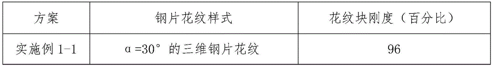

Table 5: the invention relates to a pattern rigidity comparison table of three-dimensional steel sheet patterns with different distances H4
| Scheme(s) | Pattern of steel sheet | Pattern block stiffness (percentage) |
| Examples 1 to 4 | H4-3 mm three-dimensional steel sheet pattern | 93 |
| Examples 1 to 5 | H4-4 mm three-dimensional steel sheet pattern | 100 |
| Examples 1 to 6 | H4-6 mm three-dimensional steel sheet pattern | 95 |
The three-dimensional steel sheet can reduce stress concentration and improve the shear rigidity of the pattern blocks at the same time because the three-dimensional steel sheet is provided with the convex blocks and the grooves in the transverse direction and the depth direction of the tire, and the tire mold processed by the three-dimensional steel sheet with the concave-convex structure ensures that the tire has the tire pattern grooves with the same concave-convex structure, the convex blocks and the grooves in the tire pattern grooves are in arc transition connection through the curved surfaces in the first curved surface group, the second curved surface group and the third curved surface group, and the joint part is the arc curved surface, so that the generation of larger stress concentration caused by sharp linear turning at the boundary of the pattern blocks can be avoided. When the tire rolls, the tread of the ground contact area is in a load-bearing state, so that the pattern grooves are extruded and closed, and because the grooves are of a concave-convex structure, when a vehicle accelerates or decelerates, the pattern blocks form a mutually supported state, namely, the pattern blocks are meshed through the convex blocks and the concave grooves, so that the interlocking strength of the pattern blocks is increased, the shearing rigidity of the pattern blocks is improved, the creeping of the tread pattern blocks is inhibited, the partial abrasion is reduced, and the abrasion performance of the tire is improved; meanwhile, the width of the three-dimensional steel sheet is designed by using a constraint design with a constant value, so that the width of a groove of the tire groove is kept unchanged in the running process, the pattern interlocking strength of the concave-convex structure is kept, and the abrasion performance of the tire is further improved.
The above-mentioned embodiments are merely illustrative of the preferred embodiments of the present invention, and do not limit the scope of the present invention, and various modifications and improvements made to the technical solution of the present invention by those skilled in the art without departing from the spirit of the present invention should fall within the protection scope defined by the claims of the present invention.
Claims (12)
1. A three-dimensional steel sheet for improving the wear performance of a tyre, defined by a central plane XZ and having a planar portion (10) and at least one three-dimensional portion (20), characterized in that:
the three-dimensional portion comprises a bump (210) and a groove (220) which are respectively connected with each other in an alternating arc transition mode along the transverse direction and the depth direction of the tire, each bump or groove comprises an end plane (230) which is parallel and separated from the central plane XZ, and a plurality of side faces which extend from the side faces of the end plane to the arc transition mode along the transverse direction and the depth direction of the tire respectively to form a convex side face or a concave side face, and at least one side face of each bump or groove can be jointed with the side face of the adjacent bump or groove.
2. The three-dimensional steel sheet according to claim 1, wherein an included angle α between a center line L of a plurality of side surfaces extending to the center plane XZ in the tire depth direction and the end plane is 35 to 55 °; the distance H4 between the centers of the tail end planes of the two adjacent convex blocks and the groove in the depth direction of the tire is 3.5-5.5 mm.
3. The three-dimensional steel sheet according to claim 1, wherein the width W of the three-dimensional steel sheet is a constant value and is 0.3 to 2 mm.
4. The three-dimensional steel sheet according to claim 1, wherein said three-dimensional portion has at least one continuous transverse alternating projection and groove and at least one continuous depth-wise alternating projection and groove.
5. A three-dimensional steel sheet according to claim 1, wherein the projections and recesses on both sides of the central plane XZ, the projections on one side forming a convex configuration as the concave configuration of the recesses on the other side, and the recesses on one side forming a concave configuration as the convex configuration of the projections on the other side.
6. Three-dimensional steel sheet according to claim 2, wherein said side faces comprise at least one inclined plane (240) extending from two opposite side edges of the end plane (230) in the transverse direction of the tyre towards the central plane XZ and at least three curved surfaces (250) transitionally connected in the direction of the tyre depth towards the arc of the central plane XZ on the basis of the end plane and the inclined plane.
7. The three-dimensional steel sheet according to claim 6, wherein the curved surfaces (250) include two first curved surface groups (2510) transitionally connected to the XZ arc along the tire depth direction with the end plane (230) and the inclined plane (240) as base surfaces, two second curved surface groups (2520) transitionally connected to the XZ arc along the tire depth direction with the first curved surface groups as base surfaces, and two third curved surface groups (2530) transitionally connected to the XZ arc along the tire depth direction with the second curved surface groups as base surfaces.
8. The three-dimensional steel sheet according to claim 7, wherein the first curved surface group (2510) comprises a first curved surface (2511) which takes the end plane as a base surface and extends to the central plane XZ along the depth direction of the tire, and two second curved surfaces (2512) which take the inclined plane (240) as a base surface, extends to the central plane XZ along the depth direction of the tire and are arranged on two sides of the first curved surface along the transverse direction of the tire, and the circular arc radiuses RA of the first curved surface and the second curved surface are 0.4-1 mm.
9. The three-dimensional steel sheet according to claim 8, wherein the second curved surface group (2520) includes a curved surface three (2521) extending in the tire depth direction to the center plane XZ with the curved surface one (2511) as a base surface, and two curved surfaces four (2522) extending in the tire depth direction to the center plane XZ with the curved surface two (2512) as a base surface and disposed on both sides of the curved surface three (2521) in the tire lateral direction, and the arc radii RB of the curved surfaces three and four being 1 to 3 mm.
10. The three-dimensional steel sheet according to claim 9, wherein the third curved surface group (2530) comprises a curved surface five (2531) having a curved surface three (2521) as a base surface and extending in the tire depth direction toward the center plane XZ, and two curved surfaces six (2532) having a curved surface four (2522) as a base surface and extending in the tire depth direction toward the center plane XZ and being disposed on both sides of the curved surface five (2531) in the tire lateral direction, and the arc radii RC of the curved surface five and the curved surface six are 1 to 3 mm.
11. The three-dimensional steel sheet according to claim 10, wherein α is an angle between a center line L of the first curved surface (2511), the third curved surface (2521) and the fifth curved surface (2531) and the tip plane (230).
12. A tire, characterized in that the tire tread is provided with a pattern made of the three-dimensional steel sheet according to any one of claims 1 to 11.
Priority Applications (1)
| Application Number | Priority Date | Filing Date | Title |
|---|---|---|---|
| CN202210258413.4A CN114714822B (en) | 2022-03-16 | 2022-03-16 | Three-dimensional steel sheet and tire for improving wear performance of tire |
Applications Claiming Priority (1)
| Application Number | Priority Date | Filing Date | Title |
|---|---|---|---|
| CN202210258413.4A CN114714822B (en) | 2022-03-16 | 2022-03-16 | Three-dimensional steel sheet and tire for improving wear performance of tire |
Publications (2)
| Publication Number | Publication Date |
|---|---|
| CN114714822A true CN114714822A (en) | 2022-07-08 |
| CN114714822B CN114714822B (en) | 2023-10-27 |
Family
ID=82237757
Family Applications (1)
| Application Number | Title | Priority Date | Filing Date |
|---|---|---|---|
| CN202210258413.4A Active CN114714822B (en) | 2022-03-16 | 2022-03-16 | Three-dimensional steel sheet and tire for improving wear performance of tire |
Country Status (1)
| Country | Link |
|---|---|
| CN (1) | CN114714822B (en) |
Cited By (2)
| Publication number | Priority date | Publication date | Assignee | Title |
|---|---|---|---|---|
| WO2024246644A1 (en) * | 2023-05-31 | 2024-12-05 | Pirelli Tyre S.P.A. | Winter tyre |
| WO2024246645A1 (en) * | 2023-05-31 | 2024-12-05 | Pirelli Tyre S.P.A. | Tyre |
Citations (9)
| Publication number | Priority date | Publication date | Assignee | Title |
|---|---|---|---|---|
| JP2002356105A (en) * | 2001-05-31 | 2002-12-10 | Toyo Tire & Rubber Co Ltd | Pneumatic tire |
| CN1618636A (en) * | 2003-11-20 | 2005-05-25 | 固特异轮胎和橡胶公司 | Three-dimensional sipes for treads |
| CN101022965A (en) * | 2004-08-06 | 2007-08-22 | 株式会社普利司通 | Pneumatic tire and method of producing the same |
| CN101547799A (en) * | 2006-12-07 | 2009-09-30 | 米其林技术公司 | Tread comprising dual orientation incisions |
| TW201144101A (en) * | 2010-06-08 | 2011-12-16 | Cheng Shin Rubber Ind Co Ltd | Tire tread with three-dimensional sipe |
| JP2013112130A (en) * | 2011-11-28 | 2013-06-10 | Yokohama Rubber Co Ltd:The | Pneumatic tire |
| CN106103140A (en) * | 2014-03-07 | 2016-11-09 | 普利司通美国轮胎运营有限责任公司 | Tire tread with siping as characteristic |
| CN109219530A (en) * | 2016-06-10 | 2019-01-15 | 倍耐力轮胎股份公司 | winter tires |
| CN112248721A (en) * | 2020-10-26 | 2021-01-22 | 安徽佳通乘用子午线轮胎有限公司 | Tire with three-dimensional steel sheet patterns arranged on tread |
-
2022
- 2022-03-16 CN CN202210258413.4A patent/CN114714822B/en active Active
Patent Citations (9)
| Publication number | Priority date | Publication date | Assignee | Title |
|---|---|---|---|---|
| JP2002356105A (en) * | 2001-05-31 | 2002-12-10 | Toyo Tire & Rubber Co Ltd | Pneumatic tire |
| CN1618636A (en) * | 2003-11-20 | 2005-05-25 | 固特异轮胎和橡胶公司 | Three-dimensional sipes for treads |
| CN101022965A (en) * | 2004-08-06 | 2007-08-22 | 株式会社普利司通 | Pneumatic tire and method of producing the same |
| CN101547799A (en) * | 2006-12-07 | 2009-09-30 | 米其林技术公司 | Tread comprising dual orientation incisions |
| TW201144101A (en) * | 2010-06-08 | 2011-12-16 | Cheng Shin Rubber Ind Co Ltd | Tire tread with three-dimensional sipe |
| JP2013112130A (en) * | 2011-11-28 | 2013-06-10 | Yokohama Rubber Co Ltd:The | Pneumatic tire |
| CN106103140A (en) * | 2014-03-07 | 2016-11-09 | 普利司通美国轮胎运营有限责任公司 | Tire tread with siping as characteristic |
| CN109219530A (en) * | 2016-06-10 | 2019-01-15 | 倍耐力轮胎股份公司 | winter tires |
| CN112248721A (en) * | 2020-10-26 | 2021-01-22 | 安徽佳通乘用子午线轮胎有限公司 | Tire with three-dimensional steel sheet patterns arranged on tread |
Cited By (2)
| Publication number | Priority date | Publication date | Assignee | Title |
|---|---|---|---|---|
| WO2024246644A1 (en) * | 2023-05-31 | 2024-12-05 | Pirelli Tyre S.P.A. | Winter tyre |
| WO2024246645A1 (en) * | 2023-05-31 | 2024-12-05 | Pirelli Tyre S.P.A. | Tyre |
Also Published As
| Publication number | Publication date |
|---|---|
| CN114714822B (en) | 2023-10-27 |
Similar Documents
| Publication | Publication Date | Title |
|---|---|---|
| CN114714822A (en) | Three-dimensional steel sheet for improving abrasion performance of tire and tire | |
| CA2858598A1 (en) | Snow performance peaks | |
| US10464376B2 (en) | Pneumatic tire | |
| JP5530046B2 (en) | tire | |
| CN112248721B (en) | Tire with three-dimensional steel sheet patterns arranged on tread | |
| CN115302986B (en) | Tire pattern and radial tire with same for car | |
| CN219667874U (en) | Tire with a tire cover | |
| CN109532341A (en) | Tread patterns for truck tire | |
| CN220374203U (en) | Tread pattern structure of metric all-steel load tubeless radial tire | |
| US12533914B2 (en) | Tire provided with 3D kerfs combining interlocking bands and hidden groove-type kerfs | |
| CN219564665U (en) | Tire with a tire body | |
| CN219667872U (en) | Tire with a tire cover | |
| CN214492406U (en) | Pneumatic tire | |
| JP4190076B2 (en) | Pneumatic tire and its mounting method | |
| JP2025019699A (en) | Pneumatic tires | |
| CN211942853U (en) | Radial tire with excellent comprehensive performance for high-mileage car | |
| JPH05319028A (en) | Pneumatic radial tire for heavy load | |
| CN223919042U (en) | A type of hexagonal tread blocks and the tread pattern formed by them for a high-mileage tire with all wheel positions, designed for medium- and short-distance heavy-duty applications. | |
| CN211364169U (en) | Tread capable of inhibiting partial abrasion of tire | |
| CN219821124U (en) | Car tire pattern | |
| CN223508020U (en) | Middle and short distance tyre | |
| CN223508025U (en) | Tire tread structure and tires with it | |
| CN220298229U (en) | Tire pattern and low-noise high-grip tire | |
| CN222246720U (en) | Engineering machinery tire pattern suitable for high load | |
| CN223432157U (en) | A full wheel pattern and tire for a truck |
Legal Events
| Date | Code | Title | Description |
|---|---|---|---|
| PB01 | Publication | ||
| PB01 | Publication | ||
| SE01 | Entry into force of request for substantive examination | ||
| SE01 | Entry into force of request for substantive examination | ||
| GR01 | Patent grant | ||
| GR01 | Patent grant |