CN114696470A - charger - Google Patents
charger Download PDFInfo
- Publication number
- CN114696470A CN114696470A CN202011558975.8A CN202011558975A CN114696470A CN 114696470 A CN114696470 A CN 114696470A CN 202011558975 A CN202011558975 A CN 202011558975A CN 114696470 A CN114696470 A CN 114696470A
- Authority
- CN
- China
- Prior art keywords
- magnet
- cover
- charger
- top surface
- accommodating groove
- Prior art date
- Legal status (The legal status is an assumption and is not a legal conclusion. Google has not performed a legal analysis and makes no representation as to the accuracy of the status listed.)
- Pending
Links
- 230000005291 magnetic effect Effects 0.000 claims description 49
- 230000000717 retained effect Effects 0.000 claims 2
- 230000008878 coupling Effects 0.000 description 20
- 238000010168 coupling process Methods 0.000 description 20
- 238000005859 coupling reaction Methods 0.000 description 20
- 238000001179 sorption measurement Methods 0.000 description 11
- 230000006698 induction Effects 0.000 description 6
- 125000006850 spacer group Chemical group 0.000 description 4
- 230000005672 electromagnetic field Effects 0.000 description 3
- 230000000694 effects Effects 0.000 description 2
- 230000005389 magnetism Effects 0.000 description 2
- 238000000034 method Methods 0.000 description 2
- 238000004026 adhesive bonding Methods 0.000 description 1
- 230000005540 biological transmission Effects 0.000 description 1
- 238000006243 chemical reaction Methods 0.000 description 1
- 238000010586 diagram Methods 0.000 description 1
- 230000001939 inductive effect Effects 0.000 description 1
- 238000012986 modification Methods 0.000 description 1
- 230000004048 modification Effects 0.000 description 1
- 238000000465 moulding Methods 0.000 description 1
- NJPPVKZQTLUDBO-UHFFFAOYSA-N novaluron Chemical compound C1=C(Cl)C(OC(F)(F)C(OC(F)(F)F)F)=CC=C1NC(=O)NC(=O)C1=C(F)C=CC=C1F NJPPVKZQTLUDBO-UHFFFAOYSA-N 0.000 description 1
- 239000013589 supplement Substances 0.000 description 1
Images


Classifications
-
- H—ELECTRICITY
- H02—GENERATION; CONVERSION OR DISTRIBUTION OF ELECTRIC POWER
- H02J—CIRCUIT ARRANGEMENTS OR SYSTEMS FOR SUPPLYING OR DISTRIBUTING ELECTRIC POWER; SYSTEMS FOR STORING ELECTRIC ENERGY
- H02J50/00—Circuit arrangements or systems for wireless supply or distribution of electric power
- H02J50/005—Mechanical details of housing or structure aiming to accommodate the power transfer means, e.g. mechanical integration of coils, antennas or transducers into emitting or receiving devices
-
- H—ELECTRICITY
- H01—ELECTRIC ELEMENTS
- H01F—MAGNETS; INDUCTANCES; TRANSFORMERS; SELECTION OF MATERIALS FOR THEIR MAGNETIC PROPERTIES
- H01F7/00—Magnets
- H01F7/02—Permanent magnets [PM]
- H01F7/0205—Magnetic circuits with PM in general
- H01F7/0221—Mounting means for PM, supporting, coating, encapsulating PM
-
- H—ELECTRICITY
- H02—GENERATION; CONVERSION OR DISTRIBUTION OF ELECTRIC POWER
- H02J—CIRCUIT ARRANGEMENTS OR SYSTEMS FOR SUPPLYING OR DISTRIBUTING ELECTRIC POWER; SYSTEMS FOR STORING ELECTRIC ENERGY
- H02J50/00—Circuit arrangements or systems for wireless supply or distribution of electric power
- H02J50/10—Circuit arrangements or systems for wireless supply or distribution of electric power using inductive coupling
-
- H—ELECTRICITY
- H02—GENERATION; CONVERSION OR DISTRIBUTION OF ELECTRIC POWER
- H02J—CIRCUIT ARRANGEMENTS OR SYSTEMS FOR SUPPLYING OR DISTRIBUTING ELECTRIC POWER; SYSTEMS FOR STORING ELECTRIC ENERGY
- H02J50/00—Circuit arrangements or systems for wireless supply or distribution of electric power
- H02J50/90—Circuit arrangements or systems for wireless supply or distribution of electric power involving detection or optimisation of position, e.g. alignment
-
- H—ELECTRICITY
- H02—GENERATION; CONVERSION OR DISTRIBUTION OF ELECTRIC POWER
- H02J—CIRCUIT ARRANGEMENTS OR SYSTEMS FOR SUPPLYING OR DISTRIBUTING ELECTRIC POWER; SYSTEMS FOR STORING ELECTRIC ENERGY
- H02J7/00—Circuit arrangements for charging or depolarising batteries or for supplying loads from batteries
- H02J7/0042—Circuit arrangements for charging or depolarising batteries or for supplying loads from batteries characterised by the mechanical construction
Landscapes
- Engineering & Computer Science (AREA)
- Power Engineering (AREA)
- Computer Networks & Wireless Communication (AREA)
- Physics & Mathematics (AREA)
- Electromagnetism (AREA)
- Charge And Discharge Circuits For Batteries Or The Like (AREA)
- Secondary Cells (AREA)
Abstract
本发明提供一充电器。该充电器可容置一磁体,该充电器包括一本体、一无线充电组件、一容置槽以及一盖体。无线充电组件设置于本体内,容置槽凹设于本体的顶面,盖体可拆卸式地设置于本体顶面并且覆盖容置槽。当盖体自顶面移除时,容置槽显露于外界,使磁体可以自由放入容置槽或从容置槽中移出。
The present invention provides a charger. The charger can accommodate a magnet, and the charger includes a body, a wireless charging component, an accommodating slot and a cover. The wireless charging assembly is arranged in the body, the accommodating groove is recessed on the top surface of the body, and the cover is detachably arranged on the top surface of the body and covers the accommodating groove. When the cover body is removed from the top surface, the accommodating groove is exposed to the outside, so that the magnet can be freely inserted into the accommodating groove or removed from the accommodating groove.
Description
技术领域technical field
本发明涉及一种充电装置,尤其涉及一种可拆换零件的充电器。The invention relates to a charging device, in particular to a charger with removable parts.
背景技术Background technique
现今的携带型电子装置在使用时会持续耗电,当电量过低时将无法运作,需要使用充电器对电子装置传输提供电能以补充使用时消耗的电。随着需求提高,充电器也发展出不同的充电形式,其中无线充电式的充电器也普遍被使用。无线充电型充电器,主要是以充电器内的无线充电组件对应携带型电子装置内部的充电感应线圈,利用无线充电组件与充电感应线圈彼此接近产生的电磁场变化并将其转换为电能,使充电器的电能传输给携带型电子装置,予以供电。同时,无线充电型充电器有一个特点在于,无线充电组件与充电感应线圈两者之间的位置需要靠近于一定范围内才有办法形成电磁场感应的变化,若是二者的距离太远或是彼此对应位置不够准确,可能会无法充电或导致充电效果不佳。因此现有作法是在充电器以及携带型电子装置内部各自装设磁性元件,让携带型电子装置放置于充电器上进行充电时,以磁性方式彼此吸附,并使充电感应线圈能精准对应到无线充电组件的电磁场范围,让电能有效转换及传输。Today's portable electronic devices will continue to consume power when in use, and cannot operate when the power is too low, and a charger needs to be used to transmit power to the electronic device to supplement the power consumed during use. With the increase in demand, chargers have also developed different charging forms, among which wireless charging chargers are also commonly used. The wireless charging type charger mainly uses the wireless charging component in the charger to correspond to the charging induction coil inside the portable electronic device, and uses the electromagnetic field change generated by the wireless charging component and the charging induction coil to be close to each other and convert it into electrical energy, so that the charging can be achieved. The power of the device is transmitted to the portable electronic device to supply power. At the same time, a feature of the wireless charging type charger is that the position between the wireless charging component and the charging induction coil needs to be close to a certain range in order to form a change in electromagnetic field induction. If the corresponding location is not accurate enough, it may not be able to charge or cause poor charging effect. Therefore, the existing method is to install magnetic components inside the charger and the portable electronic device, so that when the portable electronic device is placed on the charger for charging, they are magnetically attracted to each other, and the charging induction coil can accurately correspond to the wireless The electromagnetic field range of the charging component allows the efficient conversion and transmission of electrical energy.
然而,磁性元件是用做准确对位的辅助工具,并非每一款携带型电子装置都具有磁性元件,也会有适用无线充电但没有设置磁性元件或不需磁性吸附对位的携带型电子装置存在。市面上公知的充电器中,内建有磁性元件的无线充电型充电器,通常已将磁性元件固定在内部,使用者无法自行简单拆换取出,而没有内建磁性元件的无线充电型充电器,使用者也无法自行轻易将磁性元件添加入充电器内,不能简易拆换添加零件,难以让同个充电器配合不同款式的携带型电子装置的需求,相当不方便。However, magnetic components are used as auxiliary tools for accurate alignment. Not every portable electronic device has magnetic components. There are also portable electronic devices that are suitable for wireless charging but do not have magnetic components or do not require magnetic adsorption and alignment. exist. Among the well-known chargers on the market, the wireless charging type chargers with built-in magnetic components usually have the magnetic components fixed inside, and users cannot simply disassemble and take them out, and the wireless charging type chargers without built-in magnetic components , the user cannot easily add magnetic components into the charger, and cannot easily remove and replace the added parts. It is difficult to make the same charger fit the needs of different styles of portable electronic devices, which is quite inconvenient.
发明内容SUMMARY OF THE INVENTION
为了解决公知技术的问题,本发明提供一种可拆换零件的充电器。充电器内有容置槽用以放置磁性元件,并且充电器外盖能够简易拆换,将外盖拆下后能任意更换或卸除磁性元件,使用者可依据需求自由设置。本发明的充电器能够配合不同种类的携带型电子装置,达到以相同充电器可以在磁吸式功能及非磁吸式功能之间自行更换的目的,解决公知技术的问题。In order to solve the problems of the prior art, the present invention provides a charger with removable parts. There are accommodating slots in the charger for placing magnetic components, and the outer cover of the charger can be easily removed and replaced. After removing the outer cover, the magnetic components can be replaced or removed at will, and users can freely set according to their needs. The charger of the present invention can be matched with different types of portable electronic devices to achieve the purpose of self-replacement between the magnetic suction function and the non-magnetic suction function with the same charger, thereby solving the problems of the prior art.
为了达到上述目的,本发明一种充电器,该充电器可容置一磁体,该充电器包括:一本体,该本体具有一顶面;一无线充电组件,设置于该本体内,该无线充电组件可供电予一外部电子装置;一容置槽,凹设于该本体的该顶面,该容置槽用以容置该磁体;以及一盖体,可拆卸地设置于该顶面并且覆盖该容置槽;其中,该盖体可自由拆卸或装设于该顶面,当该盖体自该顶面卸除时,该容置槽显露于外界,用以将该磁体放入该容置槽或将该磁体自该容置槽中取出。In order to achieve the above object, the present invention provides a charger, which can accommodate a magnet, and the charger includes: a main body, the main body has a top surface; a wireless charging component is arranged in the main body, the wireless charging The component can supply power to an external electronic device; an accommodating groove is recessed on the top surface of the main body, the accommodating groove is used for accommodating the magnet; and a cover body is detachably disposed on the top surface and covers the accommodating groove; wherein, the cover body can be freely disassembled or installed on the top surface, when the cover body is removed from the top surface, the accommodating groove is exposed to the outside for placing the magnet into the container into the slot or take the magnet out of the slot.
较佳地,该容置槽对应该磁体,当该磁体容置于该容置槽中时,该本体具有磁性吸附力,当该磁体自该容置槽中移除时,该本体不具有磁性吸附力。Preferably, the accommodating slot corresponds to the magnet, when the magnet is accommodated in the accommodating slot, the body has a magnetic attraction force, and when the magnet is removed from the accommodating slot, the body has no magnetism Adsorption.
较佳地,该外部电子装置包括一磁性件及一充电线路,当该磁体留置于该容置槽中时,该磁体对应该磁性件,使该本体吸附该外部电子装置,并使该充电线路对应该无线充电组件。Preferably, the external electronic device includes a magnetic member and a charging circuit. When the magnet is indwelling in the receiving slot, the magnet corresponds to the magnetic member, so that the main body can attract the external electronic device and make the charging circuit. Corresponds to the wireless charging component.
较佳地,该本体包括一第一结合件,该盖体包括一第二结合件,该第一结合件设置于该顶面,该第二结合件设置于该盖体,该第一结合件对应该第二结合件,使该盖体结合于该顶面。Preferably, the body includes a first coupling piece, the cover body includes a second coupling piece, the first coupling piece is disposed on the top surface, the second coupling piece is disposed on the cover body, the first coupling piece Corresponding to the second coupling piece, the cover body is coupled to the top surface.
较佳地,该盖体设置于该顶面并且覆盖该容置槽时,该盖体封闭该容置槽。Preferably, when the cover body is disposed on the top surface and covers the accommodating groove, the cover body closes the accommodating groove.
较佳地,该盖体具有一盖底面,该磁体固定于该盖底面,并对应该容置槽。Preferably, the cover body has a cover bottom surface, and the magnet is fixed on the cover bottom surface and corresponds to the accommodating groove.
较佳地,该磁体包括一基座以及一磁铁,该磁铁设置于该基座中。Preferably, the magnet includes a base and a magnet, and the magnet is disposed in the base.
较佳地,该磁体为一环型磁性体,该容置槽为一环型槽。Preferably, the magnet is a ring-shaped magnetic body, and the accommodating groove is a ring-shaped groove.
较佳地,该无线充电组件邻近该顶面,并位于该容置槽的下方。Preferably, the wireless charging assembly is adjacent to the top surface and below the accommodating groove.
为了达到上述目的,本发明一种充电器,该充电器可容置一磁体,该充电器包括:一本体,该本体具有一顶面;一无线充电组件,设置于该本体内,该无线充电组件可供电予一外部电子装置;一盖体,该盖体具有一盖底面,该盖底面对应该本体的该顶面,并且该盖体可拆卸地覆盖该顶面;以及一容置槽,凹设于该盖体的该盖底面;其中,该盖体可自由拆卸或装设于该顶面,当该盖体自该顶面卸除时,该容置槽显露于外界,用以将该磁体放入该容置槽或将该磁体自该容置槽中取出。In order to achieve the above object, the present invention provides a charger, which can accommodate a magnet, and the charger includes: a main body, the main body has a top surface; a wireless charging component is arranged in the main body, the wireless charging The component can supply power to an external electronic device; a cover body, the cover body has a cover bottom surface, the cover bottom surface corresponds to the top surface of the main body, and the cover body detachably covers the top surface; and an accommodating groove , is recessed on the bottom surface of the cover; wherein, the cover can be freely disassembled or installed on the top surface, when the cover is removed from the top surface, the accommodating groove is exposed to the outside world for Put the magnet into the accommodating slot or take the magnet out of the accommodating slot.
较佳地,该容置槽对应该磁体,当该磁体容置于该容置槽中时,该本体具有磁性吸附力,当该磁体自该容置槽中移除时,该本体不具有磁性吸附力。Preferably, the accommodating slot corresponds to the magnet, when the magnet is accommodated in the accommodating slot, the body has a magnetic attraction force, and when the magnet is removed from the accommodating slot, the body has no magnetism Adsorption.
较佳地,该外部电子装置包括一磁性件及一充电线路,当该磁体留置于该容置槽中时,该磁体对应该磁性件,使该本体吸附该外部电子装置,并使该充电线路对应该无线充电组件。Preferably, the external electronic device includes a magnetic member and a charging circuit. When the magnet is indwelling in the receiving slot, the magnet corresponds to the magnetic member, so that the main body can attract the external electronic device and make the charging circuit. Corresponds to the wireless charging component.
较佳地,该本体包括一第一结合件,该盖体包括一第二结合件,该第一结合件设置于该顶面,该第二结合件设置于该盖体,该第一结合件对应该第二结合件,使该盖体结合于该顶面。Preferably, the body includes a first coupling piece, the cover body includes a second coupling piece, the first coupling piece is disposed on the top surface, the second coupling piece is disposed on the cover body, the first coupling piece Corresponding to the second coupling piece, the cover body is coupled to the top surface.
较佳地,该盖体覆盖该顶面时,该顶面封闭该容置槽。Preferably, when the cover body covers the top surface, the top surface closes the accommodating groove.
本发明提出的充电器结构,让使用者可简易替换内部零件,使通过更换零件的方式,使同一个充电器具有不同的磁吸附性的功能效果。The structure of the charger proposed by the present invention allows the user to easily replace the internal parts, so that the same charger can have different functional effects of magnetic adsorption by replacing the parts.
附图说明Description of drawings
图1为本发明第一较佳实施例的立体示意图。FIG. 1 is a schematic perspective view of a first preferred embodiment of the present invention.
图2为本发明第一较佳实施例的立体分解图。FIG. 2 is an exploded perspective view of the first preferred embodiment of the present invention.
图3为本发明第一较佳实施例的立体分解图。3 is an exploded perspective view of the first preferred embodiment of the present invention.
图4为本发明的磁体的立体示意图。FIG. 4 is a schematic perspective view of the magnet of the present invention.
图5为本发明的磁体的立体分解图。5 is an exploded perspective view of the magnet of the present invention.
图6为本发明不具有磁体的使用状态剖面示意图。FIG. 6 is a schematic cross-sectional view of the present invention in a use state without a magnet.
图7为本发明具有磁体的使用状态剖面示意图。FIG. 7 is a schematic cross-sectional view of the present invention with a magnet in use.
图8为本发明第二较佳实施例的立体分解图。FIG. 8 is an exploded perspective view of the second preferred embodiment of the present invention.
图9为本发明第三较佳实施例的立体分解图。FIG. 9 is an exploded perspective view of the third preferred embodiment of the present invention.
附图标记如下:The reference numbers are as follows:
1:充电器1: Charger
1’:充电器1': Charger
2:充电器2: Charger
10:本体10: Ontology
10’:本体10': body
11:顶面11: Top surface
11’:顶面11': top surface
12:第一结合件12: The first joint
12’:第一结合件12': The first joint
20:磁体20: Magnets
20’:磁体20': Magnet
20”:磁体20": Magnet
21:基座21: Pedestal
211:磁铁槽211: Magnet slot
22:磁铁22: Magnets
23:隔片23: Spacer
30:无线充电组件30: Wireless Charging Components
40:容置槽40: accommodating slot
40’:容置槽40': accommodating slot
50:盖体50: cover
50’:盖体50': cover body
501’:盖体501': cover
51:盖顶面51: Cover the top surface
52:第二结合件52: Second binding piece
52’:第二结合件52': Second binding piece
53:盖底面53: Cover bottom
53’:盖底面53': Cover Bottom
60:本体60: Ontology
61:顶面61: Top surface
62:第一结合件62: The first joint
70:无线充电组件70: Wireless charging components
80:容置槽80: accommodating slot
90:盖体90: Cover
92:第二结合件92: Second binding piece
93:盖底面93: Cover bottom
X:外部电子装置X: External Electronics
X1:磁性件X1: Magnetics
X2:充电线路X2: Charging circuit
具体实施方式Detailed ways
以下现举本发明若干较佳实施例并搭配附图进行进一步的说明。Hereinafter, some preferred embodiments of the present invention will be further described in conjunction with the accompanying drawings.
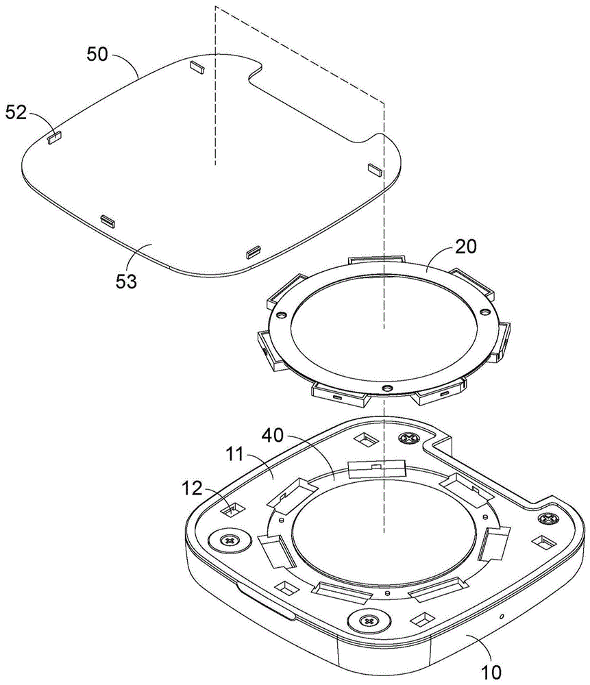
首先,说明本发明第一较佳实施例,请参阅图1、图2及图3。图1为本发明第一较佳实施例的立体示意图,图2为本发明第一较佳实施例的立体分解图,图3为本发明第一较佳实施例的立体分解图。本发明的充电器1,充电器1中可容置一磁体20。本发明的充电器1包括一本体10、一无线充电组件30、一容置槽40以及一盖体50。本体10具有一顶面11。无线充电组件30设置于本体内,无线充电组件30可以无线感应充电的方式提供电能量给一外部电子装置X(显示于图6)。容置槽40凹设于本体10的顶面11,并且容置槽40用以容置磁体20。盖体50可拆卸式地设置于本体10顶面11并且覆盖容置槽40。当盖体50自顶面11上移开或卸除时,使容置槽40显露于外界,用以将磁体20放入容置槽40或是将磁体20从容置槽40中取出。First, the first preferred embodiment of the present invention will be described, please refer to FIG. 1 , FIG. 2 and FIG. 3 . 1 is a schematic perspective view of the first preferred embodiment of the present invention, FIG. 2 is an exploded perspective view of the first preferred embodiment of the present invention, and FIG. 3 is an exploded perspective view of the first preferred embodiment of the present invention. In the
详细而言,充电器1的本体10还包括一第一结合件12设置于顶面11。盖体50还包括一盖顶面51、一第二结合件52以及一盖底面53,第二结合件52设置于盖底面53。本体10的第一结和件12对应盖体50的第二结合件52,第一结合件12与第二结合件52互相扣合,使盖体50结合于本体10的顶面11。无线充电组件30设置于本体10内,且无线充电组件30邻近顶面11并位于容置槽40的下方。磁体20可为独立元件,并且可被使用者自由取出或放入。容置槽40的大小、形状、深度对应磁体20,使容置槽40能完整容纳入磁体20。盖体50可由使用者自由拆卸或组装于本体10的顶面11,当盖体50组装结合于本体10顶面11时,盖体50会覆盖容置槽40,并且盖体50会将容置槽40封闭而使容置槽40不会露出于外界。当使用者将盖体50自本体10顶面11上移开或卸除时,顶面11将不会被盖体50遮蔽,同时使容置槽40显露于外界,让使用者放置磁体20进入容置槽40中,后续再将盖体50结合回本体10的顶面11,使盖体50覆盖容置槽40并将磁体20封闭于容置槽40中。若使用者不需使用磁体20时,可将盖体50再次开启或移除,让容置槽40与磁体20再次显露于外界,将磁体20从容置槽40中取出来并将盖体50盖回本体10的顶面11覆盖容置槽40,即可将磁体20从本体10中移除,便于自由拆换。Specifically, the
当磁体20被容置或封闭于容置槽40中,且盖体50覆盖于本体10的顶面11时,本体10具有磁性吸附力,可以磁性吸附外部电子装置X(显示于图6),并将外部电子装置X(显示于图6)定位于盖体50的盖顶面51进行充电。当磁体自该容置槽40中移除,且盖体50覆盖于本体10的顶面11时,本体10不具有磁性吸附力,因此外部电子装置X(显示于图6)可放置于盖顶面51上的任意位置进行充电。When the
以下说明磁体20的结构,请参阅图4及图5,图4为本发明的磁体的立体示意图,图5为本发明的磁体的立体分解图。磁体20还包括一基座21、一磁铁22以及一隔片23。基座21的外型、大小、高度与容置槽40相对应,并且基座21还包括一磁铁槽211,磁铁槽211的数量对应磁铁22的数量。磁铁22设置于基座21的磁铁槽211中,隔片23设置于磁铁22上方,用于保护磁铁22并将磁铁22限制在磁铁槽211中。基座21可容纳于容置槽40,并且磁铁22和隔片23也会被一并带进容置槽40中,因此当磁体20被封闭于容置槽40中时,本体就具有磁性吸附力。磁铁22可复数排列于基座21中,并且磁铁22可用粘贴、夹合或是一体成形方式设置于基座21,或是先将磁铁22设置在一底板(图中未示),让磁铁22固定好间距和位置后,再将磁铁22与底板(图中未示)一起设置在基座21中。本发明较佳实施例的磁体20为环型磁性体,容置槽40为环型槽。复数磁铁22围绕成环状排列在环状的基座21中,并且环状的基座21可容纳入环形的容置槽40中。The structure of the
以下为本发明的充电器1不具有磁体20以及具有磁体20时的不同使用状态说明,请参阅图6以及图7,图6为本发明不具有磁体的使用状态剖面示意图,图7为本发明具有磁体的使用状态剖面示意图。外部电子装置X更可包括一磁性件X1以及一充电线路X2。磁性件X1以及充电线路X2设置在外部电子装置X内,充电线路X2用以感应无线充电组件30并进行充电,磁性件X1用以磁性吸附与定位外部电子装置X于充电器1上。请参阅图6,充电器1不具有磁体20时的操作状态说明。充电器1的容置槽40被盖体50所覆盖,且磁体20并未设置在容置槽40中时,本体10不具磁性吸附力,此时外部电子装置X可放置于盖顶面51上的任意位置,使充电线路X2感应到无线充电组件30即可进行充电。但是,由于外部电子装置X与本体10之间并没有让彼此定位对准的磁性吸附力存在,充电线路X2可能会因为距离太远或是没有对应在感应范围内而无法感应到无线充电组件30,导致无法顺利充电。续请参阅图7,充电器1具有磁体20时的操作状态说明。充电器1的容置槽40被盖体50所覆盖,且磁体20设置在容置槽40中时,本体10具磁性吸附力,此时外部电子装置X放置于盖顶面51上时,磁体20会磁性吸附磁性件X1,使外部电子装置X定位在本体10上且不会轻易位移或脱落,同时使充电线路X2能准确对应到本体10内的无线充电组件30,让充电线路X2维持在无线充电组件30的感应范围中进行充电,维持稳定充电效能。The following is a description of the different usage states of the
磁性件X1并非外部电子装置X的必要元件,因此若外部电子装置X没有设置磁性件X1时,充电器1的本体10内就不需设置磁体20,若外部电子装置X内部设置有磁性件X1时,充电器1的本体10内可设置磁体20,使用者可依照外部电子装置X的状态,自由调整磁体20设置或取出。The magnetic component X1 is not a necessary component of the external electronic device X, so if the external electronic device X does not have the magnetic component X1, the
续说明本发明第二较佳实施例的结构,请参阅图8本发明第二较佳实施例的立体分解图。第二较佳实施例的部分结构以及操作状态与第一较佳实施例相同,因此相同之处就不多加赘述。第二较佳实施例的充电器1’,充电器1’中可容置一磁体20’。本发明的充电器1’包括一本体10’、一无线充电组件(图中未示)、一容置槽40’以及一盖体50’。本体10’具有一顶面11’以及一第一结合件12’。盖体50’具有一盖底面53’以及一第二结合件52’。磁体20’固定于盖体50’的盖底面53’。无线充电组件(图中未示)设置于本体1’内。容置槽40’凹设于本体10’的顶面11’,并且容置槽40’用以容置磁体20’。盖体50’可拆卸式地设置于本体10’的顶面11’,第二结合件52’可对应结合第一结合件12,使盖体50’结合在本体10上。当盖体50’设置于本体10’上并覆盖容置槽40’时,固定于盖底面53’的磁体20’可直接对应嵌入容置槽40’中并被封闭在本体10’内,使本体10’具有磁性吸附力。此外,若使用者不需要磁体20’时可以替换使用另外一种盖体501’,盖体501’不具有磁体20’因此设置在本体10’时,磁体20’并没有进入容置槽40’中,本体10’也不会具有磁性吸附力。使用者可以依照需求,替换使用不同种类的盖体50’或是盖体501’。Continuing to describe the structure of the second preferred embodiment of the present invention, please refer to FIG. 8 which is an exploded perspective view of the second preferred embodiment of the present invention. Part of the structure and operation state of the second preferred embodiment are the same as those of the first preferred embodiment, so the similarities will not be repeated. In the charger 1' of the second preferred embodiment, a magnet 20' can be accommodated in the charger 1'. The charger 1' of the present invention includes a main body 10', a wireless charging assembly (not shown in the figure), an accommodating slot 40' and a
本发明第三较佳实施例的结构,请参阅图9本发明第三较佳实施例的立体分解图。第三较佳实施例的部分结构以及操作状态与第一较佳实施例相同,因此相同之处就不多加赘述。第三较佳实施例的充电器2,充电器2中可容置一磁体20”。充电器2包括一本体60、一无线充电组件70、一容置槽80以及一盖体90。本体60具有一顶面61以及一第一结合件62。盖体90还包括一第二结合件92以及一盖底面93。无线充电组件30设置于本体内。容置槽80凹设于盖体90的盖底面93,并且容置槽80用以容置磁体20”。盖体90可拆卸式地设置于本体60,盖体90的盖底面93对应本体60的顶面61,第二结合件92对应结合第一结合件62,使盖体90结合在本体60上。盖体90设置于本体60时,本体60的顶面61覆盖并封闭盖体90上容置槽80。盖体90可自由拆卸或装设于本体60的顶面61,当盖体90自顶面61上卸除时,盖体90上的容置槽80会暴露于外界,用以将磁体20”放入容置槽80或自容置槽80中取出。For the structure of the third preferred embodiment of the present invention, please refer to FIG. 9 which is an exploded perspective view of the third preferred embodiment of the present invention. Part of the structure and operation state of the third preferred embodiment are the same as those of the first preferred embodiment, so the similarities will not be repeated. In the
本发明的磁体20、20’、20”并不限定外型,可依照不同充电器种类而调整外型、深度以及设置位置。本发明的第一结合件12、12’、62以及第二结合件52、52’、92并不限定结合的方式,可以是卡扣接合、磁力结合或是粘贴结合。The
本发明的充电器可以容纳设置磁体,并且结构上可以简易将磁体放入或取出,提供使用者自由调整充电器的磁性吸附力,以对应不同款式的外部电子装置,提高便利性并且满足无线充电感应效能以及装置定位的需求。The charger of the present invention can accommodate and set the magnet, and the magnet can be easily put in or taken out in structure, providing the user to freely adjust the magnetic adsorption force of the charger to correspond to different styles of external electronic devices, improving convenience and satisfying wireless charging. Sensing performance and device positioning requirements.
上所述仅为本发明的较佳实施例,并非用以限定本发明的权利要求范围,因此凡其他未脱离本发明所公开的精神下所完成的等效改变或修饰,均应包含于本发明的范围内。The above descriptions are only preferred embodiments of the present invention and are not intended to limit the scope of the claims of the present invention. Therefore, any other equivalent changes or modifications made without departing from the spirit disclosed in the present invention shall be included in the present invention. within the scope of the invention.
Claims (14)
Priority Applications (1)
| Application Number | Priority Date | Filing Date | Title |
|---|---|---|---|
| CN202011558975.8A CN114696470A (en) | 2020-12-25 | 2020-12-25 | charger |
Applications Claiming Priority (1)
| Application Number | Priority Date | Filing Date | Title |
|---|---|---|---|
| CN202011558975.8A CN114696470A (en) | 2020-12-25 | 2020-12-25 | charger |
Publications (1)
| Publication Number | Publication Date |
|---|---|
| CN114696470A true CN114696470A (en) | 2022-07-01 |
Family
ID=82129266
Family Applications (1)
| Application Number | Title | Priority Date | Filing Date |
|---|---|---|---|
| CN202011558975.8A Pending CN114696470A (en) | 2020-12-25 | 2020-12-25 | charger |
Country Status (1)
| Country | Link |
|---|---|
| CN (1) | CN114696470A (en) |
-
2020
- 2020-12-25 CN CN202011558975.8A patent/CN114696470A/en active Pending
Similar Documents
| Publication | Publication Date | Title |
|---|---|---|
| TWI731828B (en) | Element removable charger | |
| US8237401B2 (en) | Recharging system and electronic device | |
| JP4774439B2 (en) | Electronic device electromagnetic connector | |
| US8248025B2 (en) | Charging system capable of charging electronic device by electromagnetic induction | |
| US20200185968A1 (en) | Rechargeable battery and hearing aid system | |
| KR20120110674A (en) | Wireless charger for portable device | |
| US9479007B1 (en) | Induction charging system | |
| US20230080598A1 (en) | Accessory case for multiple charger types | |
| US11699911B2 (en) | Smart charger with built in connector | |
| CN114696470A (en) | charger | |
| WO2022205863A1 (en) | Protective case for wireless earphones, wireless earphone charging device, and terminal | |
| US20210057937A1 (en) | Modular charging devices and methods for using them | |
| CN215010665U (en) | A protective housing and wireless earphone battery charging outfit and mobile terminal for wireless earphone | |
| CN213602452U (en) | Magnetic wireless charger | |
| CN211298703U (en) | Chargeable spectacle case device | |
| CN215378476U (en) | Wireless portable power source that fills | |
| CN219611399U (en) | Wireless charging mobile power supply | |
| CN219436682U (en) | Wireless treasured that charges is inhaled to magnetism | |
| CN220066956U (en) | Charger and electronic equipment | |
| CN219678198U (en) | Three-in-one wireless charger | |
| CN212572113U (en) | Magnetic wireless charging device | |
| CN214204984U (en) | Wireless charging device | |
| CN220544745U (en) | Combined wireless charger | |
| CN219739977U (en) | Magnetic wireless charging support | |
| CN112994273A (en) | Terminal device and wireless transmitting assembly |
Legal Events
| Date | Code | Title | Description |
|---|---|---|---|
| PB01 | Publication | ||
| PB01 | Publication | ||
| SE01 | Entry into force of request for substantive examination | ||
| SE01 | Entry into force of request for substantive examination |