CN114423020B - LoRaWAN network downlink route control method and system - Google Patents
LoRaWAN network downlink route control method and system Download PDFInfo
- Publication number
- CN114423020B CN114423020B CN202210071598.8A CN202210071598A CN114423020B CN 114423020 B CN114423020 B CN 114423020B CN 202210071598 A CN202210071598 A CN 202210071598A CN 114423020 B CN114423020 B CN 114423020B
- Authority
- CN
- China
- Prior art keywords
- occupancy rate
- bandwidth occupancy
- link bandwidth
- sequence
- path
- Prior art date
- Legal status (The legal status is an assumption and is not a legal conclusion. Google has not performed a legal analysis and makes no representation as to the accuracy of the status listed.)
- Active
Links
- 238000000034 method Methods 0.000 title claims abstract description 60
- 230000005540 biological transmission Effects 0.000 claims abstract description 75
- 230000006854 communication Effects 0.000 claims abstract description 41
- 238000012549 training Methods 0.000 claims abstract description 16
- YHXISWVBGDMDLQ-UHFFFAOYSA-N moclobemide Chemical compound C1=CC(Cl)=CC=C1C(=O)NCCN1CCOCC1 YHXISWVBGDMDLQ-UHFFFAOYSA-N 0.000 claims abstract 22
- 238000004891 communication Methods 0.000 claims description 39
- 238000010586 diagram Methods 0.000 claims description 25
- 238000012545 processing Methods 0.000 claims description 19
- 230000004927 fusion Effects 0.000 claims description 15
- 238000007689 inspection Methods 0.000 claims description 12
- 238000012360 testing method Methods 0.000 claims description 12
- 238000004364 calculation method Methods 0.000 claims description 10
- 230000000694 effects Effects 0.000 claims description 10
- 238000001914 filtration Methods 0.000 claims description 6
- 230000008859 change Effects 0.000 claims description 5
- 238000007781 pre-processing Methods 0.000 claims description 5
- 238000012937 correction Methods 0.000 claims description 4
- 108010072348 sperm releasing substance Proteins 0.000 description 10
- 238000002198 surface plasmon resonance spectroscopy Methods 0.000 description 10
- 238000011217 control strategy Methods 0.000 description 8
- 230000000875 corresponding effect Effects 0.000 description 5
- 230000008569 process Effects 0.000 description 4
- 230000001276 controlling effect Effects 0.000 description 3
- 238000005259 measurement Methods 0.000 description 3
- 230000009286 beneficial effect Effects 0.000 description 2
- 238000005516 engineering process Methods 0.000 description 2
- 238000002474 experimental method Methods 0.000 description 2
- 238000009499 grossing Methods 0.000 description 2
- 230000006872 improvement Effects 0.000 description 2
- 230000007246 mechanism Effects 0.000 description 2
- 238000005457 optimization Methods 0.000 description 2
- 238000005070 sampling Methods 0.000 description 2
- NAWXUBYGYWOOIX-SFHVURJKSA-N (2s)-2-[[4-[2-(2,4-diaminoquinazolin-6-yl)ethyl]benzoyl]amino]-4-methylidenepentanedioic acid Chemical compound C1=CC2=NC(N)=NC(N)=C2C=C1CCC1=CC=C(C(=O)N[C@@H](CC(=C)C(O)=O)C(O)=O)C=C1 NAWXUBYGYWOOIX-SFHVURJKSA-N 0.000 description 1
- 238000013459 approach Methods 0.000 description 1
- 230000002596 correlated effect Effects 0.000 description 1
- 230000008878 coupling Effects 0.000 description 1
- 238000010168 coupling process Methods 0.000 description 1
- 238000005859 coupling reaction Methods 0.000 description 1
- 230000007547 defect Effects 0.000 description 1
- 238000011156 evaluation Methods 0.000 description 1
- 238000013507 mapping Methods 0.000 description 1
- 238000006386 neutralization reaction Methods 0.000 description 1
- 230000002787 reinforcement Effects 0.000 description 1
- 238000011160 research Methods 0.000 description 1
- 238000013468 resource allocation Methods 0.000 description 1
- 238000013112 stability test Methods 0.000 description 1
Images


Classifications
-
- H—ELECTRICITY
- H04—ELECTRIC COMMUNICATION TECHNIQUE
- H04W—WIRELESS COMMUNICATION NETWORKS
- H04W16/00—Network planning, e.g. coverage or traffic planning tools; Network deployment, e.g. resource partitioning or cells structures
- H04W16/22—Traffic simulation tools or models
-
- H—ELECTRICITY
- H04—ELECTRIC COMMUNICATION TECHNIQUE
- H04W—WIRELESS COMMUNICATION NETWORKS
- H04W40/00—Communication routing or communication path finding
- H04W40/02—Communication route or path selection, e.g. power-based or shortest path routing
- H04W40/12—Communication route or path selection, e.g. power-based or shortest path routing based on transmission quality or channel quality
-
- Y—GENERAL TAGGING OF NEW TECHNOLOGICAL DEVELOPMENTS; GENERAL TAGGING OF CROSS-SECTIONAL TECHNOLOGIES SPANNING OVER SEVERAL SECTIONS OF THE IPC; TECHNICAL SUBJECTS COVERED BY FORMER USPC CROSS-REFERENCE ART COLLECTIONS [XRACs] AND DIGESTS
- Y02—TECHNOLOGIES OR APPLICATIONS FOR MITIGATION OR ADAPTATION AGAINST CLIMATE CHANGE
- Y02D—CLIMATE CHANGE MITIGATION TECHNOLOGIES IN INFORMATION AND COMMUNICATION TECHNOLOGIES [ICT], I.E. INFORMATION AND COMMUNICATION TECHNOLOGIES AIMING AT THE REDUCTION OF THEIR OWN ENERGY USE
- Y02D30/00—Reducing energy consumption in communication networks
- Y02D30/70—Reducing energy consumption in communication networks in wireless communication networks
Landscapes
- Engineering & Computer Science (AREA)
- Computer Networks & Wireless Communication (AREA)
- Signal Processing (AREA)
- Data Exchanges In Wide-Area Networks (AREA)
Abstract
The invention relates to a method and a system for controlling a downlink route of a LoRaWAN (local area network), wherein the method comprises the following steps: modeling the LoRaWAN network downlink route topological relation based on the SDN framework to obtain a link bandwidth occupancy rate sequence in a preset time period among all switches in a network downlink route model acquisition model; determining model parameters of an ARIMA model according to the sequence, training the ARIMA model, and obtaining a predicted value of the link bandwidth occupancy rate among all the switches according to the trained ARIMA model; and determining the transmission delay of the data packet transmitted from the centralized controller to the data receiving and transmitting end by the LoRaWAN network, and determining the selection sequence of each path transmitted from the centralized controller to the data receiving and transmitting end by using a triangular modular operator according to the predicted value of the bandwidth occupancy rate of the link and the transmission delay of the data packet. The SDN framework, the predicted value of the ARIMA model and the data packet transmission delay are introduced, so that the data transmission efficiency in the downlink communication process is improved.
Description
Technical Field
The invention relates to the field of network downlink communication, in particular to a LoRaWAN network downlink route control method and system based on an SDN framework.
Background
The LoRaWAN network technology is one of main technologies in a low-power-consumption wide area network, and in the LoRaWAN downlink communication, transmission delay and packet loss rate are important indexes of the quality of service of the LoRaWAN network downlink communication. In order to reduce the packet loss rate and transmission delay in the downstream communication of the LoRaWAN network and improve the communication performance, many researches have been made to reduce the limitation of the duty ratio and the receiving window of the terminal node on the gateway sending data by optimizing the channel evaluation mechanism and using the polling broadcasting mechanism, thereby indirectly improving the reliability and the time delay performance of the downstream communication. The invention provides a LoRaWAN network downlink route control method and system based on SDN framework, which are mainly focused on MAC layer and application implementation of LoRaWAN protocol, and the scheme does not relate to control strategy of LoRaWAN downlink communication route selection, so that data control and forwarding are correlated together, coupling is strong, and along with increase of downlink load rate, capacity of processing data congestion of the LoRaWAN network is easy to reach upper limit, thereby reducing data transmission efficiency.
Disclosure of Invention
The invention aims to provide a LoRaWAN network downlink route control method and system, which are characterized in that a LoRaWAN downlink route model built by an SDN framework is combined with an ARIMA model to build a data prediction model of downlink load occupancy rate, and a LoRaWAN network downlink route control strategy is designed according to a link bandwidth occupancy rate predicted value and the data packet transmission delay, so that the efficiency of data transmission is improved.
In order to achieve the above object, the present invention provides the following solutions:
a LoRaWAN network downlink route control method comprises the following steps:
modeling the LoRaWAN network downlink route topological relation based on the SDN framework to obtain a network downlink route model; the network downlink routing model comprises a centralized controller, a plurality of switches and a plurality of data receiving and transmitting ends; each switch is connected with the centralized controller; each exchanger is connected with one data receiving and transmitting end; each of the switches is connected to at least one of the remaining switches;
acquiring the link bandwidth occupancy rate in a preset time period between the switches in the network downlink routing model, and obtaining a link bandwidth occupancy rate sequence;
determining model parameters of an ARIMA model according to the link bandwidth occupancy rate sequence and training the ARIMA model to obtain a trained ARIMA model; the model parameters comprise an autoregressive term number, a moving average term number, an autocorrelation coefficient and a weighted average coefficient;
Obtaining a predicted value of the link bandwidth occupancy rate of each link between the switches according to the trained ARIMA model;
determining the transmission delay of a data packet transmitted from the centralized controller to the data receiving and transmitting end by the downlink communication service data of the LoRaWAN network;
and fusing the predicted value of the link bandwidth occupancy rate and the transmission delay of the data packet by using a triangular module operator, and determining the selection sequence of each path of the service data transmitted from the centralized controller to the data receiving and transmitting end by combining the sequence of the link bandwidth occupancy rate.
A lorewan network downstream route control system, comprising:
the network downlink route model building module is used for modeling the LoRaWAN network downlink route topological relation based on the SDN framework to obtain a network downlink route model; the network downlink routing model comprises a centralized controller, a plurality of switches and a plurality of data receiving and transmitting ends; each switch is connected with the centralized controller; each exchanger is connected with one data receiving and transmitting end; each of the switches is connected to at least one of the remaining switches;
the system comprises a link bandwidth occupancy rate sequence acquisition module, a link bandwidth occupancy rate sequence acquisition module and a network downlink routing model, wherein the link bandwidth occupancy rate sequence acquisition module is used for acquiring the link bandwidth occupancy rate in a preset time period between the switches in the network downlink routing model to obtain a link bandwidth occupancy rate sequence;
The model training module is used for determining the model parameters of the ARIMA model according to the link bandwidth occupancy rate sequence and training the ARIMA model to obtain a trained ARIMA model; the model parameters comprise an autoregressive term number, a moving average term number, an autocorrelation coefficient and a weighted average coefficient;
the prediction module is used for obtaining a predicted value of the link bandwidth occupancy rate of each link between the switches according to the trained ARIMA model;
the transmission delay acquisition module is used for determining the transmission delay of a data packet transmitted from the centralized controller to the data receiving and transmitting end by the downlink communication service data of the LoRaWAN network;
and the path selection module is used for fusing the predicted value of the link bandwidth occupancy rate and the transmission delay of the data packet by utilizing a triangular module operator, and determining the selection sequence of each path of the service data transmitted from the centralized controller to the data receiving and transmitting end by combining the sequence of the link bandwidth occupancy rate.
According to the specific embodiment provided by the invention, the invention discloses the following technical effects:
the invention provides a method and a system for controlling a downlink route of a LoRaWAN (local area network), wherein the method comprises the following steps: modeling the LoRaWAN network downlink route topological relation based on the SDN framework to obtain a link bandwidth occupancy rate sequence in a preset time period among all switches in a network downlink route model acquisition model; determining model parameters of an ARIMA model according to the sequence, training the ARIMA model, and obtaining a predicted value of the link bandwidth occupancy rate among all the switches according to the trained ARIMA model; determining the transmission delay of a data packet transmitted from a centralized controller to a data receiving and transmitting end by a LoRaWAN network, fusing the predicted value of the link bandwidth occupancy rate and the transmission delay of the data packet by using a triangular module operator, and determining the selection sequence of each path of the service data transmitted from the centralized controller to the data receiving and transmitting end by combining the link bandwidth occupancy rate sequence. The SDN framework, the predicted value of the ARIMA model and the data packet transmission delay are introduced, so that the data transmission efficiency in the downlink communication process is improved.
Drawings
In order to more clearly illustrate the embodiments of the present invention or the technical solutions in the prior art, the drawings that are needed in the embodiments will be briefly described below, and it is obvious that the drawings in the following description are only some embodiments of the present invention, and other drawings may be obtained according to these drawings without inventive effort for a person skilled in the art.
Fig. 1 is a flowchart of a method for controlling a downlink route of a lorewan network provided in embodiment 1 of the present invention;
fig. 2 is a diagram of a lo wan network downlink communication SDN architecture provided in embodiment 1 of the present invention;
FIG. 3 is a flowchart of ARIMA modeling provided in example 1 of the present invention;
fig. 4 is an autocorrelation chart of a link bandwidth occupancy sequence provided in embodiment 1 of the present invention;
fig. 5 is a second order differential autocorrelation diagram of a link bandwidth occupancy sequence provided in embodiment 1 of the present invention;
fig. 6 is a second order differential partial autocorrelation chart of the link bandwidth occupancy sequence provided in embodiment 1 of the present invention;
fig. 7 is a schematic diagram of the bandwidth occupancy of each path at time t provided in embodiment 1 of the present invention;
fig. 8 is a schematic diagram of each path bandwidth occupancy score at time t+t provided in embodiment 1 of the present invention;
Fig. 9 is a schematic diagram of an SDN-based minimum path-selection routing control policy provided in embodiment 1 of the present invention;
FIG. 10 is a graph showing the prediction effect of ARIMA model provided in embodiment 1 of the present invention;
fig. 11 is a comparison chart of packet loss rates of the lown communication provided in embodiment 1 of the present invention;
fig. 12 is a graph of average transmission delay versus for the lown communication provided in embodiment 1 of the present invention;
fig. 13 is a graph showing average bandwidth occupancy rate of the lown communication link provided in embodiment 1 of the present invention;
fig. 14 is a block diagram of a downstream routing control system of a lorewan network provided in embodiment 2 of the present invention.
Detailed Description
The following description of the embodiments of the present invention will be made clearly and completely with reference to the accompanying drawings, in which it is apparent that the embodiments described are only some embodiments of the present invention, but not all embodiments. All other embodiments, which can be made by those skilled in the art based on the embodiments of the invention without making any inventive effort, are intended to be within the scope of the invention.
The invention aims to provide a LoRaWAN network downlink route control method and system, which are characterized in that a LoRaWAN downlink route model built by an SDN framework is combined with an ARIMA model to build a data prediction model of downlink load occupancy rate, and a LoRaWAN network downlink route control strategy is designed according to a link bandwidth occupancy rate predicted value and the data packet transmission delay, so that the efficiency of data transmission is improved.
In order that the above-recited objects, features and advantages of the present invention will become more readily apparent, a more particular description of the invention will be rendered by reference to the appended drawings and appended detailed description.
Example 1
As shown in fig. 1, this embodiment provides a method for controlling a downlink route of a lorewan network, including:
s1: modeling the LoRaWAN network downlink route topological relation based on the SDN framework to obtain a network downlink route model; the network downlink routing model comprises a centralized controller, a plurality of switches and a plurality of data receiving and transmitting ends; each switch is connected with the centralized controller; each exchanger is connected with one data receiving and transmitting end; each of the switches is connected to at least one of the remaining switches;
s2: acquiring the link bandwidth occupancy rate in a preset time period between the switches in the network downlink routing model, and obtaining a link bandwidth occupancy rate sequence;
s3: determining model parameters of an ARIMA model according to the link bandwidth occupancy rate sequence and training the ARIMA model to obtain a trained ARIMA model; the model parameters comprise an autoregressive term number, a moving average term number, an autocorrelation coefficient and a weighted average coefficient;
The specific step S3 further includes:
preprocessing the link bandwidth occupancy rate sequence by using an S-G smooth filtering method and a sliding window method to obtain a preprocessed link bandwidth occupancy rate sequence; the method specifically comprises the following steps:
discretizing the link bandwidth occupancy rate sequence, and determining that the width of a sliding filter window is n=2m+1;
for t -m ,t -m+1 ,...,t 0 ,t 1 ,...,t m-1 ,t m+1 Calculating a polynomial fitting value by adopting a k-1 degree polynomial to obtain the link bandwidth occupancy rate after time dispersionTo a polynomial system of linear equations;
determining fitting coefficients of the polynomial linear equation set by adopting a least square method;
by t -m ,t -m+1 ,...,t 0 ,t 1 ,...,t m-1 ,t m+1 Replacing t by the average value of the polynomial fitting values at the moment h The occupancy rate of the link bandwidth at the moment is obtained to obtain t h The occupancy rate of the link bandwidth after time replacement; h=0, 1,2,..m-1, m+1;
according to t 0 To t m+1 Sliding in the direction of (t) h The polynomial fitting values are respectively replaced by the t at the moment h The occupancy rate of the link bandwidth after time replacement; let h=h+1, return to step "utilize t" -m ,t -m+1 ,...,t 0 ,t 1 ,...,t m-1 ,t m+1 Replacing t by the average value of the polynomial fitting values at the moment h And traversing all data within the width of the sliding filter window from the link bandwidth occupancy rate at the moment to obtain the preprocessed link bandwidth occupancy rate sequence.
Specifically, step S3 specifically includes:
(1) Determining the weighted average coefficient according to the fitting coefficient;
(2) Preliminarily judging whether the link bandwidth occupancy rate sequence is stable or not by using an autocorrelation diagram observation method, and obtaining a first judgment result; the method specifically comprises the following steps:
constructing an autocorrelation chart according to the link bandwidth occupancy rate sequence; the link bandwidth occupancy rate sequence is the preprocessed link bandwidth occupancy rate sequence;
observing whether tail cutting and tailing conditions exist in the autocorrelation graph;
if the autocorrelation graph has neither tail cutting nor tailing, the preprocessed link bandwidth occupancy rate sequence is non-stationary data; the tail cutting means that after a certain delay order, the autocorrelation coefficients are all 0; the tailing means that the autocorrelation coefficient has an attenuation trend along with the change of the delay order, but the unevenness is 0; otherwise, the preprocessed link bandwidth occupancy rate sequence is stable data.
(3) When the first judgment result is yes, determining the number of autoregressive terms, the number of moving average terms and the autocorrelation coefficient according to an autocorrelation diagram and a bias correlation diagram of the link bandwidth occupancy rate sequence; the method specifically comprises the following steps:
Calculating the autocorrelation coefficients according to the expression of the autocorrelation diagram of the link bandwidth occupancy sequence;
determining the numerical range of the autoregressive term number according to the corresponding delay order when the autocorrelation coefficient in the autocorrelation graph is truncated for the first time;
determining the numerical range of the moving average term number according to the delay order corresponding to the first occurrence of the attenuation trend of the partial autocorrelation coefficient in the partial autocorrelation graph;
establishing a plurality of ARIMA models according to each value in the numerical range of the autoregressive term number and each value in the numerical range of the moving average term number;
respectively training a plurality of ARIMA models by using the link bandwidth occupancy rate sequences to obtain a plurality of trained ARIMA models;
and comparing the prediction effects of a plurality of the trained ARIMA models, and selecting the optimal parameter combination of the autoregressive term number and the moving average term number.
(4) When the first judgment result is negative, performing ADF (automatic frequency correction) inspection on the current link bandwidth occupancy rate sequence to obtain a first ADF inspection result, and judging whether the first ADF inspection result is larger than the ADF value of each confidence interval or not to obtain a second judgment result; ADF test is time series stationarity test.
(5) If the second judgment result is yes, the link bandwidth occupancy rate sequence is a stable sequence, and the step of determining the autoregressive terms number, the moving average terms number and the autocorrelation coefficients according to an autocorrelation diagram and a bias correlation diagram of the link bandwidth occupancy rate sequence is returned;
(6) If the second judgment result is negative, carrying out differential processing on the link bandwidth occupancy rate sequence to obtain a differential link bandwidth occupancy rate sequence;
(7) Performing ADF (automatic frequency correction) inspection on the current differential link bandwidth occupancy rate sequence to obtain a second ADF inspection result, and judging whether the second ADF inspection result is larger than the ADF value of each confidence interval or not to obtain a third judgment result;
(8) When the third judging result is negative, carrying out differential processing on the differential link bandwidth occupancy rate sequence to obtain a multi-order differential link bandwidth occupancy rate sequence; the link bandwidth occupancy rate sequence after the multi-order difference is made to be the link bandwidth occupancy rate sequence after the current difference, and the second ADF test result of the link bandwidth occupancy rate sequence after the current difference is calculated is returned to the step until the link bandwidth occupancy rate sequence after the current difference is stable data;
(9) And when the third judging result is yes, determining the number of the autoregressive terms, the number of the moving average terms and the autocorrelation coefficient according to the autocorrelation diagram and the bias correlation diagram of the current differential link bandwidth occupancy rate sequence. The calculation method of the number of autoregressive terms, the number of moving average terms, and the autocorrelation coefficient in this step is the same as that in step (3).
S4: obtaining a predicted value of the link bandwidth occupancy rate of each link between the switches according to the trained ARIMA model;
s5: determining the transmission delay of a data packet transmitted from the centralized controller to the data receiving and transmitting end by the downlink communication service data of the LoRaWAN network; the expression of the data packet transmission delay is:
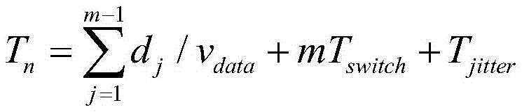
wherein T is n Representing a LoRaWAN downstream communication data slave path R n The total duration of time from the originating end to the destination end of (1), wherein the path R n Comprising a plurality of links j ;d j Representing link l j Is a length of (2); v data Representing the propagation speed of the information; t (T) switch Switching time delay between nodes; m is a pathR n The total number of switches; t (T) jitter Representing random jitter time delay.
S6: and fusing the predicted value of the link bandwidth occupancy rate and the transmission delay of the data packet by using a triangular module operator, and determining the selection sequence of each path of the service data transmitted from the centralized controller to the data receiving and transmitting end by combining the sequence of the link bandwidth occupancy rate.
The step S6 specifically includes:
determining the largest predicted value of the link bandwidth occupancy rate in each path between the centralized controller and the data receiving and transmitting end;
determining the score of each maximum predicted value of the link bandwidth occupancy rate to obtain the bandwidth occupancy rate score of each path;
fusing the bandwidth occupancy rate score of each path with the data packet transmission delay of the corresponding path by using a triangular module operator to obtain score and delay fusion data of each path;
calculating the path selectivity of each path according to the score and time delay fusion data of each path and the maximum link bandwidth occupancy rate in each path in the link bandwidth occupancy rate sequence;
determining the sequence of transmitting data by each path between the centralized controller and the data receiving and transmitting end according to each path selectivity, specifically comprising:
preferentially selecting the path with the minimum path selectivity for data transmission;
when the values of the path selectivities of the different paths are equal, preferentially selecting the path with the least total number of the switches in the paths for data transmission;
when the values of the path selectivities of the different paths are equal and the total number of the switches is equal, the paths with low frequency are preferentially selected for data transmission.
In this embodiment, a lo wan downlink routing model built by using an SDN framework is combined with an improved ARIMA to build a data prediction model of downlink load occupancy rate, and the following effects can be achieved by designing a lo wan network downlink routing control method: (1) Building a downlink bandwidth occupancy prediction model from traffic data helps to analyze the downlink resource allocation situation so that the downlink path can be planned with a minimum path-selective routing control strategy. (2) The improved ARIMA model can reduce the fluctuation of a data set, can also keep the periodicity and regularity, and ensures the accuracy of a final prediction model. (3) The method solves the problems of high packet loss rate, high transmission delay and the like of the downlink communication of the LoRaWAN network.
In order to make the technical solution of the present invention more clearly understood by those skilled in the art, the following detailed description will be provided:
step 1: based on the SDN framework, the lowwan network downstream routing topology is modeled and represented as g= (V, L), where v= { V 1 ,v 2 ,...,v i And for a switch node set in the LoRaWAN downlink communication network, i represents a switch node number, i epsilon N, and N is a positive integer. L= { L 1 ,l 2 ,...,l j The symbol } represents a link set, j represents a link number, j e N. As shown in fig. 2, the SDN controller is mainly responsible for managing network states, making routes for downstream traffic data, and the like, and the switch supporting the OpenFlow protocol is mainly responsible for processing, forwarding data and collecting network state parameters according to the flow table. Switch v i Only downstream communication data of the port connected with the port is received and transmitted by each port. Each host is intended as a server side and a gateway in the LoRaWAN network and is responsible for receiving and transmitting downlink communication data.
Step 2: obtaining relevant flow information data from the step 1, and setting a link l j With the exchange v a Q-port and v of (2) b Is connected with g port of the network, the link bandwidth sequence (t time link l) at each time included in the preset time period (in one acquisition period) j The used bandwidth sequence b j (t)) can be represented by formula (1):

in the formula (1), the components are as follows, representing the switch v at time t a The number of forwarding bytes of q-port of +.>
 Representing the switch v at time t b G port forwarding byte count. q, g denote the port number (q, g e N) of the switch. T is the switch state parameter acquisition period.
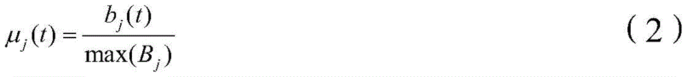
Link l j The maximum bandwidth that can be transmitted is denoted as max (B j ) Time t link l j Bandwidth occupancy μ of (2) j (t) can be represented by formula (2):
step 3: compared with the standard ARIMA modeling process, the method adds a data stationarity processing step before performing sequence difference calculation processing, introduces a Savitzky-Golay smoothing filtering method, and has the core idea that the occupancy rate mu of the original sequence link bandwidth is j And (t) after discretization processing, performing k-order polynomial fitting on data points in a window with a certain length, performing least square fitting on a given high-order polynomial in a sliding window to obtain a weighting coefficient of S-G filtering, and calculating according to the weighting coefficient to obtain a result of each data point after smoothing formula processing. Calculating according to the step 2 to obtain the occupancy rate mu of the link bandwidth j (t) and preprocessing the data, wherein the method mainly comprises the following steps:
3.1 occupancy μ of Link Bandwidth for original sequence j (t) discretizing, and setting the sliding filter window width as n' =2m+1, wherein the available link bandwidth occupancy rate of each measurement point is y= (y) -m ,y -m+1 ,...,y 0 ,y 1 ,...,y m-1 ,y m ) The abscissa time is divided into equal intervals of the interval T, and the abscissa of the sliding window sampling point is set to x= (T) -m ,t -m+1 ,...,t 0 ,t 1 ,...,t m-1 ,t m ) Fitting data points within a window using a k-1 th order polynomialThe fitting function is as in equation (3).

In the middle of Is the k-1 coefficient, x is the sampling time point, y is the occupancy mu of the link bandwidth at the current moment j (x)。/>
3.2, using equation (3) to fit to each measurement point, then n such equations are made, constituting a system of k-element linear equations. To solve the system of equations, n should be equal to or greater than k, with n > k generally chosen. Set polynomial fitting coefficient as Fitting parameters A are determined by least squares fitting. This gives:
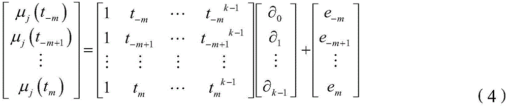
e in (4) m Is a constant term in a linear system of equations. Least squares solution for A The method comprises the following steps:

in the formula (5), let x= (t) -m ,t -m+1 ,...,t 0 ,t 1 ,...,t m-1 ,t m ),Y=[μ j (t -m ),...,μ j (t m )] T Here Y has the same meaning as Y.
Model filter values of Y The method comprises the following steps:

B=X·(X T ·X) -1 ·X T (7)
3.3, use at time point t -m ,t -m+ 1,...,t 0 ,t 1 ,...,t m-1 ,t m The link bandwidth occupancy y (polynomial fit value) of the data of (a) replaces t 0 Time-of-day link bandwidth occupancy μ j (t 0 ) Then slide forward in turn until the data in the window is traversed, i.e. until t 0 To t m The occupation rate of the link bandwidth at the moment is replaced. Obtaining the occupancy rate mu of the link bandwidth after processing according to the calculation process and the formula (8) j (t)。
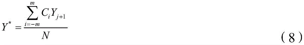
In the formula (8), N is the width of the sliding window, C i For weighting coefficients, i.e. fitting parameters A Y j+1 And Y is the original link bandwidth occupancy rate sequence data and the link bandwidth occupancy rate sequence data after preprocessing respectively.
Step 4: performing ARIMA time sequence modeling on the data subjected to filtering processing in the step 3, and predicting the occupancy rate mu of the link bandwidth at the time t+T according to the existing data at the time T j (t+t) for subsequent calculation of the downstream communication path selectivity of the lorewan network. The general autoregressive moving model ARIMA (p, d, q) predictive expression is:

in formula (9), y t Epsilon for time-series link bandwidth occupancy t At tRandom error of engraving; p is the order of the model; y is t-r The observation value of the time sequence at the time t-r; a, a r ,β r The autocorrelation coefficients of the autoregressive model (AR) and the moving average Model (MA), respectively, and the regression parameter c is a constant. The model can be seen as a combination of an autoregressive AR (p) model and a moving average MA (q) model, where when p is zero, the model is equivalent to the moving average MA (q) model; when q is zero, the model is equivalent to an autoregressive AR (p) model. The autoregressive moving-product moving average model is ARIMA (p, d, q) model, and p, d, q in the model are the autoregressive term number, the time sequence difference times and the moving average term number respectively. The ARIMA model building flow is shown in FIG. 3. The data acquisition and preprocessing part has been performed in steps 2,3 in the figure.
4.1, before building the time sequence model, firstly judging whether the data is stable or not. The method for checking the stationarity of the time series is generally an autocorrelation diagram observation method, and the calculation expression is as follows:
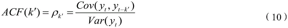
in the formula (10), y t Occupancy μ of link bandwidth at time t j (t),ρ k′ As an autocorrelation coefficient, k' represents a delay order.
FIG. 4 is a link l j The autocorrelation diagram of the bandwidth occupancy sequence is divided into tailing and truncating cases. The tail cutting means that after a certain delay order, the coefficients are all 0; tailing means that the correlation coefficient has a tendency to decay with the change in the delay order, but is not all 0. As can be seen from fig. 4, the sequence autocorrelation plot is neither trailing nor truncated and can be considered a non-stationary time sequence. Thus, the link bandwidth occupancy data is analyzed using an autoregressive moving average model (ARIMA).
4.2, in the step 4.1, the link bandwidth occupancy rate sequence can be regarded as a non-stationary sequence, differential processing is needed to be carried out on the sequence according to the steps in the modeling flow, and time sequence stability test, namely ADF test, is carried out on the stability of the original sequence and the first-order and second-order differential sequences of the original sequence respectively, and the results are shown in table 1.
TABLE 1 ADF test results

Assuming that the sequences to be examined are non-stationary sequences, 1%,5% and 10% in Table 1 correspond to 99%,95% and 90% confidence intervals, ADF values are shown, and it is known from Table 1 that ADF test results of the original sequence->
 The absolute values of the values are smaller than the absolute values of 1%,5% and 10% levels, so that the original assumption of non-stable sequence cannot be refused; first order differential sequence->
 The absolute value of the value is greater than 5%, the absolute value of the 10% level, less than the absolute value of the 1% level, and therefore the original hypothesis cannot be rejected at the 1% level; second order differential sequence->
 The absolute value of the value is larger than that of 1%,5% and 10%, and the original assumption can be refused at the levels of 1%,5% and 10%, so that the fact that a single second-order differential sequence does not exist can be judged, and the sequence is stable. In addition, table 1 also shows that, after the second order difference is performed on the sequence, the reception probability originally assumed in the ADF test is 0, and the second order difference sequence is also proved to be stable. It can thus be determined that in the ARIMA model the value of the parameter d can take 2.
The determination of p and q values in the ARIMA model is generally divided into two steps: firstly, obtaining the approximate range of parameters by means of an autocorrelation graph and a bias correlation graph of a stationary sequence after d times of difference; then, models of different parameters are established, and the optimal parameter combination is selected by comparing the model effects. The specific parameter determination method is shown in table 2.
TABLE 2 ARIMA (p, d, q) order determination
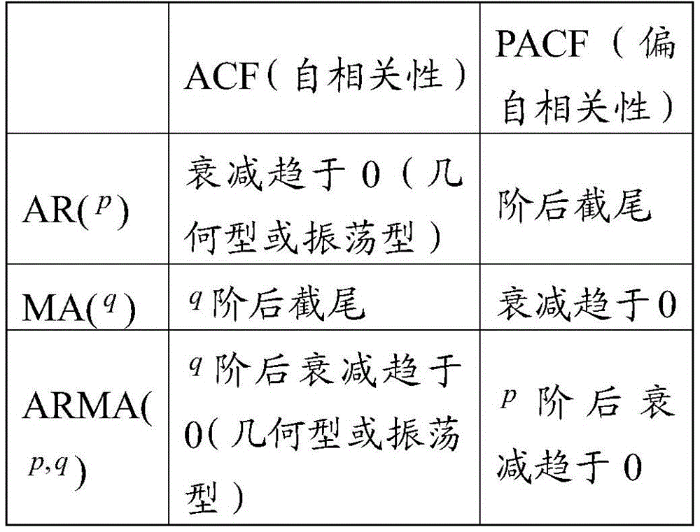
Fig. 5 is a second order differential sequence autocorrelation diagram of the downlink bandwidth occupancy, fig. 6 is a second order differential sequence partial autocorrelation diagram of the downlink bandwidth occupancy, and it can be seen from fig. 5 and 6: the autocorrelation coefficient ACF is truncated after the 3 phase, and can be approximately considered that the second-order differential sequence obeys MA (3) or MA (4), when the hysteresis order is 3, the ACF is started to be within a 95% confidence interval and is obviously different from zero; the partial autocorrelation coefficient PACF starts to show a decay trend after phase 2 and is truncated after phase 7, and the second order differential sequence can be considered to obey AR (3), AR (4) or AR (5). Fig. 6 shows that the partial autocorrelation coefficients also appear to have some singular values after the 4 th order, but these values do not affect the final result. Thus, the models initially selected were ARIMA (2, 2), ARIMA (2, 3), ARIMA (3, 2), ARIMA (3,2,3), ARIMA (4,2,2), and ARIMA (4, 2, 3).
4.4 establishing the p, d, q parameters of the ARIMA model according to the above procedure, applying equation (9), and applying t f Time link bandwidth occupancy μ j And (T) putting the model into training calculation, setting r=T, and predicting the link bandwidth occupancy rate at the next moment T, as shown in the formula (11).

Mu in the formula (11) j (t+T) is the link after prediction j The bandwidth occupancy, p, q is the order determined in step 4.3, a T Is the autocorrelation coefficient of the AR model, calculated by equation (10), where the value of the corner mark T corresponds to the delay order, β T For weighted average coefficients of MA model, i.e. fitting parameters, ε calculated in step 3 t+T The random error at time t+T is given, and c is a constant.
5、Link l derived from the prediction in step 4 j Bandwidth occupancy μ j (t+T) and establishing a LoRaWAN downlink route control strategy. The LoRaWAN downlink communication service selects a path with low bandwidth occupancy rate, which is more beneficial to the real-time reliable transmission of data. t time path R n Is defined by the maximum link bandwidth occupancy mu in the set of paths j As shown in fig. 7, the bandwidth occupancy of the path at time t can be expressed by equation (12):
CB n =max[μ j (t)] (12)
in the formula, CB n For the t-moment path R n A bandwidth occupancy maximum of (2); l (L) j Is the path R n The links involved in the network. In FIG. 7, node v a And node v b Between, path R 1 The largest link bandwidth occupancy of (a) is mu 1 (t) =0.5, according to equation (12), the t-time path R 1 Bandwidth occupancy CB 1 =0.5, similarly, path R 2 The bandwidth occupancy is CB 2 =0.3, path R 3 The bandwidth occupancy is CB 3 =0.75. Predicting and obtaining the occupancy rate mu of the link bandwidth at the time t+T by the method (11) j (t+T), path R n Path bandwidth occupancy score PS n Maximum link bandwidth occupancy score s from a set of paths j (t+T) is determined as shown in FIG. 8. t+T time path R n The bandwidth occupancy score may be represented by equation (13):
PS n =max[s j (t+T)] (13)
in fig. 8, the source node v a To the destination node v b Between, path R 1 Maximum link bandwidth occupancy score s in j (t+T) is 1, and the path bandwidth occupancy PS at time t+T is according to equation (13) 1 =1. Similarly, path R 2 Bandwidth occupancy PS of (2) 2 =3, path R 3 Bandwidth occupancy PS of (2) 3 =3。
The transmission delay of the data packet of the downlink communication service of the LoRaWAN network is mainly influenced by the length of a link and the processing capacity of an SDN switch, and the total transmission delay of service data passing through a path is the sum of the delay generated by the transmission link and a switch node, and can be represented by the following formula (14):
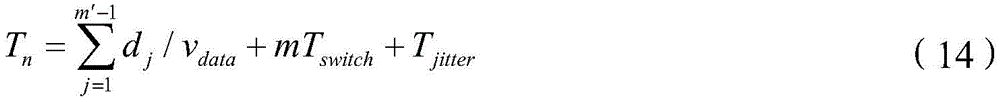
in the formula (14), T n Representing a LoRaWAN downstream communication data slave path R n For a total length of time from the originating end to the destination end. d, d j Representing link l j Length v of (v) data Representing the propagation speed of the information. T (T) switch For the exchange delay between nodes, m' is the path R n Total number of SDN switches, T jitter Representing random jitter time delay.
The minimum path-selective routing control strategy (Minimum Path Selection Routing Control Strategy, mps rcs) is shown in fig. 9. As can be seen from fig. 9, in the SDN centralized control architecture of the lorewan downstream communication network, the SDN controller periodically collects the port state parameter P of the switch a,q (t) and flow Table State parameter F a (t) deriving downstream traffic data to facilitate calculation of bandwidth occupancy on each link. The proposed LBOP-ARIMA model predicts a link bandwidth occupancy score s at time t+T according to historical state parameters j (t+T); and calculating a service transmission path by adopting a minimum path selectivity routing strategy and then issuing a flow table entry to the switch.
Adopting a triangular module operator in fuzzy mathematics to predict bandwidth occupancy rate value PS at t+T moment of LoRaWAN downlink communication transmission path n Transmission delay T n Fusion, converting the multi-objective optimization routing problem into a single objective optimization problem, and for unifying measurement standards, performing the method on CB (circuit board) because of different time bandwidth occupancy rate, bandwidth occupancy rate predicted value and transmission delay dimension of paths n ,PS n And T n And (5) performing standardization treatment. CB after processing time bandwidth occupancy by (15) n To obtain CB' n The method comprises the steps of carrying out a first treatment on the surface of the Processing the predicted bandwidth occupancy score PS with equation (16) n After which PS 'is obtained' n The method comprises the steps of carrying out a first treatment on the surface of the Processing the transmission delay T by using (17) n Obtaining T n '。

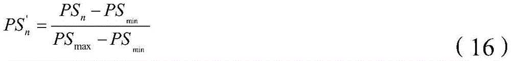

In the formula (15), CB min ,CB max The minimum value and the maximum value of the bandwidth occupancy rate at the moment t in the alternative path set are respectively. PS in the formula (16) min ,PS max Representing the minimum and maximum values of the bandwidth occupancy prediction values of the paths in the path set, respectively. In the formula (17), T max Indicating the maximum transmission delay tolerable for the LoRaWAN downlink communication service.
The triangular modulus operator is shown in formula (18):

wherein x is 1 ,x 2 Representing the predicted bandwidth occupancy score PS at time t+T, two parameters involved in fusion n Transmission delay T n ,x 1 ,x 2 ∈[0,1],Y′(x 1 ,x 2 ) And the single target measure value obtained after the fusion parameter processing.
To facilitate calculation and comparison of the path selectivity Q between different transmission paths, CB 'is used for' n ,PS' n And T n ' use type Mapping to [0.5,1 ]]On to obtain->
 And->
And-> Then combining (16) and triangular dieThe operator-combining law, the path selectivity Q can be expressed by equation (19),

according to the reinforcement of the similar information of the triangular modular operator, the parameter selection directions participating in fusion are consistent (path parameter selection And->
And-> Paths with smaller values are more beneficial to the transmission of the downlink communication paths), the importance or unimportance degree of the alternative paths is highlighted after fusion, namely, the selection degree Q of the transmission paths is obtained according to the formula (17), and the degree of the selected or unselected transmission paths is highlighted by the Q. Furthermore, the path parameters are tempered using the triangular modulo operator>
 And->
And-> The contradiction in the selection process, the selected degree of the transmission path is determined by the neutralization value Q of the path parameters.
Calculating the selectivity of a plurality of transmission paths between a source node and a destination node by using the formula (19), and preferentially selecting the smallest path as a main transmission path when a downlink communication data packet is transmitted; when the Q values of the different paths are equal, the path R is preferentially selected n Paths with the least total number of switches; when the Q values of different paths are the same and the total number of switches passed through is the same, a path with a lower frequency of use is preferentially selected.
In this embodiment, according to the SDN architecture shown in fig. 2, a lown downstream communication network topology structure is built on a Mininet platform, a Ryu controller is adopted to centrally control network resources, and a bandwidth testing tool iporf is used to simulate network traffic. The maximum bandwidth of each link is set to 100Mbit/s. Setting distance parameters of links, settingv data =2×10⁸m/s,T switch =0.1ms,T jitter =0.1 ms. When the LoRaWAN downlink communication transmission is simulated, the change of the request bandwidth value of the downlink service data packet in the network obeys normal distribution, and the occurrence probability of downlink service requests with different importance obeys poisson distribution. During experiments, the network parameters are adjusted to change the distribution state of downlink service data types in the network: host sends the minimum and maximum concurrency of UDP (user datagram protocol ) data; minimum request duration and maximum request duration of data transmission; minimum and maximum values of downlink communication request bandwidth and average request bandwidth of LoRaWAN downlink communication data.
In order to verify the effect of the proposed ARIMA model, the prediction results after the basic step and the improvement step of the ARIMA model are selected for further comparison, and one section of link l in the LoRaWAN downlink network is selected j The bandwidth occupancy sequence data of (2) is subjected to modeling prediction, and the model prediction effect is shown in fig. 10.
As can be seen in fig. 10, the rms error was used to evaluate the goodness of fit within the model samples, with rms errors before and after the improvement steps of 9.4363 and 1.1883. The prediction result shows that: by introducing an S-G filtering method and a sliding window method to preprocess data, the stability of ARIMA modeling steps on time sequence data is optimized, the root mean square error of the improved prediction model is reduced by 87% compared with that of an original model, the model accuracy is effectively improved, and the link bandwidth occupancy rate mu is improved j The (t+t) predicted value is also very close to the true value. The LoRaWAN network downstream communication packet loss rate, average transmission delay and network link average bandwidth occupancy of the proposed routing control strategy (MPSRCS) is compared with the shortest path routing strategy (Shortest Path Routing Strategy, SPRS), congestion relief routing strategy (Hybrid Congestion Alleviation Routing Strategy, HCARS), and the segment first adapted routing strategy (Online Increasing fit first Segment Routing Strategy, OI-SRS). Setting network parameter CR when testing influence of different routing strategies on network performance min =25,CR max =35,RB max =40Mbit/s,RB min =0.0625Mbit/s,RT max =20s,RT min =10s, step-wise increase the average requested bandwidth, analyze the network performance index under different routing policies: the comparison experiment result of the packet loss rate is shown in fig. 11, the comparison of the average transmission delay of the downlink communication is shown in fig. 12, and the comparison result of the average bandwidth occupancy rate of the link is shown in fig. 13.
In FIG. 11, as the network load increases gradually, the packet loss rate with MPSRCS is significantly lower than SPRS, HCARS, OI-SRS. When the network load gradually increases and approaches the maximum bandwidth of a link and congestion occurs, the SPRS strategy can not adjust the transmission path in time, so that the packet loss rate is rapidly increased; the OI-SRS method carries out route adjustment through segmented flow scheduling, when the load rate is low, compared with an SPRS strategy effect, the effect is improved, but when the link load rate exceeds 50%, the packet loss rate also increases sharply, and the limitation is high; although the HCARS strategy is a dynamic routing strategy, the future link bandwidth occupancy rate and different service priorities are not considered, so that the sudden service and partial service with higher priority and low tolerable delay are easy to cause data packet loss; the MPSRCS strategy overcomes the defects of HCARS, predicts the bandwidth occupancy rate of a future link, and when the network load is large, the packet loss rate is under the other three strategies.
Considering the difference of different downlink service data transmission delay requirements in the LoRaWAN network, it is assumed that the average transmission delay of the X ' type downlink service data successfully transmitted in the (T, t+T) period is T (X '), and the maximum tolerable transmission delay of the downlink service is Tmax (X '). Setting the type of the downlink service data of the LoRaWAN network as the average transmission delay T of the downlink service data of the 3, X' type delay Can be calculated using formula (18):

in fig. 12, when the network load is low, the average delay of the OI-SRS, SPRS and HCARS strategies is lower than that of the mps rcs, but as the network load increases, the delay variation of the SPRS is the largest and the delay variation of the mps rcs is the smallest. This is because the SPRS strategy does not optimize the congestion path according to the real-time status of the link, and thus the transmission delay increases rapidly. The OI-SRS always causes delay increase when considering the segmented routing, the network delay stability is poor, the HCARS strategy is greatly influenced by the bandwidth occupancy rate of the neighbor nodes when considering the real-time state of the link, and the local optimal path is easy to select. The MPSRCS policy considers the load balancing problem, and the initial average delay is higher because the shortest path is not necessarily selected when the path is planned, but the stability of the network average delay is better in the process of gradually increasing the network load.
In fig. 13, the SPRS policy first slows down the growth speed, because when the SPRS policy performs path selection, the data flow is allocated to the corresponding shortest path, which may cause a situation that a plurality of downlink data packets are allocated to the same path, which may easily cause uneven allocation of link resources, so as to reduce the average bandwidth occupancy rate of the whole network link. The link congestion handling performance of the OI-SRS strategy is poor, reaching the upper limit level first. The HCARS strategy regulates and controls after congestion occurs, and as the average request bandwidth gradually increases, the processing capacity finally reaches the upper limit, the link congestion is easy to occur, and the average bandwidth occupancy rate of the link is reduced. The average bandwidth occupancy rate of the link of the MPSRCS is higher than that of the SPRS, the OI-SRS and the HCARS, so that congestion control is performed in advance due to the fact that the congestion condition of the link in the future is predicted, the congestion relieving capability of a strategy is improved, and a reference is provided for a downlink route control method of the LoRaWAN network.
Example 2
As shown in fig. 14, this embodiment provides a lowwan network downlink route control system, including:
the network downlink route model building module M1 is used for modeling the LoRaWAN network downlink route topological relation based on the SDN framework to obtain a network downlink route model; the network downlink routing model comprises a centralized controller, a plurality of switches and a plurality of data receiving and transmitting ends; each switch is connected with the centralized controller; each exchanger is connected with one data receiving and transmitting end; each of the switches is connected to at least one of the remaining switches;
A link bandwidth occupancy rate sequence obtaining module M2, configured to obtain a link bandwidth occupancy rate within a preset time period between the switches in the network downlink routing model, so as to obtain a link bandwidth occupancy rate sequence;
the model training module M3 is used for determining the model parameters of the ARIMA model according to the link bandwidth occupancy rate sequence and training the ARIMA model to obtain a trained ARIMA model; the model parameters comprise an autoregressive term number, a moving average term number, an autocorrelation coefficient and a weighted average coefficient;
the prediction module M4 is used for obtaining a predicted value of the link bandwidth occupancy rate of each link between the switches according to the trained ARIMA model;
a transmission delay acquisition module M5, configured to determine a transmission delay of a data packet of the downstream communication service data of the lowwan network transmitted from the centralized controller to the data transceiver;
and the path selection module M6 is used for fusing the predicted value of the link bandwidth occupancy rate and the transmission delay of the data packet by utilizing a triangular module operator and determining the selection sequence of each path of the service data transmitted from the centralized controller to the data receiving and transmitting end by combining the sequence of the link bandwidth occupancy rate.
The path selection module M6 specifically includes:
a maximum value determining unit M61, configured to determine a maximum predicted value of the link bandwidth occupancy rate in each path between the centralized controller and the data transceiver;
a score determining unit M62, configured to determine a score of each maximum link bandwidth occupancy prediction value, and obtain a bandwidth occupancy score of each path;
the data fusion unit M63 is used for fusing the bandwidth occupancy rate score of each path with the data packet transmission delay of the corresponding path by utilizing a triangular modulus operator to obtain score and delay fusion data of each path;
a selection calculation unit M64, configured to calculate a path selectivity of each path according to the score and the time delay fusion data of each path and the maximum link bandwidth occupancy rate in each path in the link bandwidth occupancy rate sequence;
and a path selection sequence acquiring unit M65, configured to determine the sequence of transmitting data between the centralized controller and the data transceiver according to each path selection degree.
For the system disclosed in the embodiment, since it corresponds to the method disclosed in the embodiment, the description is relatively simple, and the relevant points refer to the description of the method section.
The principles and embodiments of the present invention have been described herein with reference to specific examples, the description of which is intended only to assist in understanding the methods of the present invention and the core ideas thereof; also, it is within the scope of the present invention to be modified by those of ordinary skill in the art in light of the present teachings. In view of the foregoing, this description should not be construed as limiting the invention.
Claims (6)
1. The control method for the downlink route of the LoRaWAN is characterized by comprising the following steps of:
modeling the LoRaWAN network downlink route topological relation based on the SDN framework to obtain a network downlink route model; the network downlink routing model comprises a centralized controller, a plurality of switches and a plurality of data receiving and transmitting ends; each switch is connected with the centralized controller; each exchanger is connected with one data receiving and transmitting end; each of the switches is connected to at least one of the remaining switches;
acquiring the link bandwidth occupancy rate in a preset time period between the switches in the network downlink routing model, and obtaining a link bandwidth occupancy rate sequence;
determining model parameters of an ARIMA model according to the link bandwidth occupancy rate sequence and training the ARIMA model to obtain a trained ARIMA model; the model parameters comprise an autoregressive term number, a moving average term number, an autocorrelation coefficient and a weighted average coefficient;
Obtaining a predicted value of the link bandwidth occupancy rate of each link between the switches according to the trained ARIMA model;
determining the transmission delay of a data packet transmitted from the centralized controller to the data receiving and transmitting end by the downlink communication service data of the LoRaWAN network;
fusing the predicted value of the link bandwidth occupancy rate and the transmission delay of the data packet by using a triangular module operator, and determining the selection sequence of each path of the service data transmitted from the centralized controller to the data receiving and transmitting end by combining the sequence of the link bandwidth occupancy rate;
determining the model parameters of the ARIMA model according to the link bandwidth occupancy rate sequence, and training the ARIMA model, wherein the method further comprises the following steps before obtaining the trained ARIMA model:
preprocessing the link bandwidth occupancy rate sequence by using an S-G smooth filtering method and a sliding window method to obtain a preprocessed link bandwidth occupancy rate sequence; the method specifically comprises the following steps:
discretizing the link bandwidth occupancy rate sequence, and determining that the width of a sliding filter window is n=2m+1;
for t -m ,t -m+1 ,...,t 0 ,t 1 ,...,t m-1 ,t m+1 Calculating a polynomial fitting value by adopting a k-1 degree polynomial to obtain a polynomial linear equation set;
Determining fitting coefficients of the polynomial linear equation set by adopting a least square method;
by t -m ,t -m+1 ,...,t 0 ,t 1 ,...,t m-1 ,t m+1 Mean value of polynomial fitting values at time instant replaces t h The occupancy rate of the link bandwidth at the moment is obtained to obtain t h The occupancy rate of the link bandwidth after time replacement; h=0, 1,2,..m-1, m+1;
according to t 0 To t m+1 Sliding in the direction of (t) h The polynomial fitting values are respectively replaced by the t at the moment h The occupancy rate of the link bandwidth after time replacement; let h=h+1, return to step "utilize t" -m ,t -m+1 ,...,t 0 ,t 1 ,...,t m-1 ,t m+1 Replacing t by the average value of the polynomial fitting values at the moment h The link bandwidth occupancy at the momentThe rate is traversed until all data in the width of the sliding filter window are traversed, and the preprocessed link bandwidth occupancy rate sequence is obtained;
determining the model parameters of an ARIMA model according to the link bandwidth occupancy rate sequence and training the ARIMA model to obtain a trained ARIMA model, and specifically comprising:
determining the weighted average coefficient according to the fitting coefficient;
preliminarily judging whether the link bandwidth occupancy rate sequence is stable or not by using an autocorrelation diagram observation method, and obtaining a first judgment result;
when the first judgment result is yes, determining the number of autoregressive terms, the number of moving average terms and the autocorrelation coefficient according to an autocorrelation diagram and a bias correlation diagram of the link bandwidth occupancy rate sequence;
When the first judgment result is negative, performing ADF (automatic frequency correction) inspection on the current link bandwidth occupancy rate sequence to obtain a first ADF inspection result, and judging whether the first ADF inspection result is larger than the ADF value of each confidence interval or not to obtain a second judgment result; the ADF test is a time sequence stationarity test;
if the second judgment result is yes, the link bandwidth occupancy rate sequence is a stable sequence, and the step of determining the autoregressive terms number, the moving average terms number and the autocorrelation coefficients according to an autocorrelation diagram and a bias correlation diagram of the link bandwidth occupancy rate sequence is returned;
if the second judgment result is negative, carrying out differential processing on the link bandwidth occupancy rate sequence to obtain a differential link bandwidth occupancy rate sequence;
performing ADF (automatic frequency correction) inspection on the current differential link bandwidth occupancy rate sequence to obtain a second ADF inspection result, and judging whether the second ADF inspection result is larger than the ADF value of each confidence interval or not to obtain a third judgment result;
when the third judging result is negative, carrying out differential processing on the differential link bandwidth occupancy rate sequence to obtain a multi-order differential link bandwidth occupancy rate sequence; the link bandwidth occupancy rate sequence after the multi-order difference is made to be the link bandwidth occupancy rate sequence after the current difference, and the second ADF test result of the link bandwidth occupancy rate sequence after the current difference is calculated is returned to the step until the link bandwidth occupancy rate sequence after the current difference is stable data;
When the third judging result is yes, determining the number of autoregressive terms, the number of moving average terms and the autocorrelation coefficient according to an autocorrelation graph and a bias correlation graph of the current differential link bandwidth occupancy sequence;
the method for determining the selection sequence of each path of the service data transmitted from the centralized controller to the data receiving and transmitting end by combining the link bandwidth occupancy rate predicted value and the data packet transmission delay through utilizing a triangular modular operator specifically comprises the following steps:
determining the largest predicted value of the link bandwidth occupancy rate in each path between the centralized controller and the data receiving and transmitting end;
determining the score of each maximum predicted value of the link bandwidth occupancy rate to obtain the bandwidth occupancy rate score of each path;
fusing the bandwidth occupancy rate score of each path with the data packet transmission delay of the corresponding path by using a triangular module operator to obtain score and delay fusion data of each path;
calculating the path selection degree of each path according to the score and time delay fusion data of each path and the maximum link bandwidth occupancy rate of each path in the link bandwidth occupancy rate sequence;
And determining the sequence of transmitting data by each path between the centralized controller and the data receiving and transmitting end according to each path selectivity.
2. The method of claim 1, wherein the preliminary determining whether the link bandwidth occupancy sequence is stationary by using an autocorrelation graph observation method, to obtain a first determination result, specifically includes:
constructing an autocorrelation chart according to the link bandwidth occupancy rate sequence; the link bandwidth occupancy rate sequence is the preprocessed link bandwidth occupancy rate sequence;
observing whether tail cutting and tailing conditions exist in the autocorrelation graph;
if the autocorrelation graph has neither tail cutting nor tailing, the preprocessed link bandwidth occupancy rate sequence is non-stationary data; the tail cutting means that after a certain delay order, the autocorrelation coefficients are all 0; the tailing means that the autocorrelation coefficient has a decay trend along with the change of the delay order, but is not 0; otherwise, the preprocessed link bandwidth occupancy rate sequence is stable data.
3. The method according to claim 1, wherein said determining the number of autoregressive terms, the number of moving average terms, and the autocorrelation coefficients from the autocorrelation and bias correlation diagrams of the link bandwidth occupancy sequence comprises:
Calculating the autocorrelation coefficients according to the expression of the autocorrelation diagram of the link bandwidth occupancy sequence;
determining the numerical range of the autoregressive term number according to the corresponding delay order when the autocorrelation coefficient in the autocorrelation graph is truncated for the first time;
determining the numerical range of the moving average term number according to the delay order corresponding to the first occurrence of the attenuation trend of the partial autocorrelation coefficient in the partial autocorrelation graph;
establishing a plurality of ARIMA models according to each value in the numerical range of the autoregressive term number and each value in the numerical range of the moving average term number;
respectively training a plurality of ARIMA models by using the link bandwidth occupancy rate sequences to obtain a plurality of trained ARIMA models;
and comparing the prediction effects of a plurality of the trained ARIMA models, and selecting the optimal parameter combination of the autoregressive term number and the moving average term number.
4. The method of claim 1, wherein the expression for determining a transmission delay of the data packet for the transmission of the lowwan downstream communication service data from the centralized controller to the data transceiver is:

wherein T is n Representing a LoRaWAN downstream communication data slave path R n The total duration of time from the originating end to the destination end of (1), wherein the path R n Comprising a plurality of links j ;d j Representing link l j Is a length of (2); v data Representing the propagation speed of the information; t (T) switch Switching time delay between nodes; m' is the path R n The total number of switches; t (T) jitter Representing random jitter time delay.
5. The method according to claim 1, wherein determining the order of data transmission between the centralized controller and the data transceiver according to each path selectivity specifically includes:
preferentially selecting the path with the minimum path selectivity for data transmission;
when the values of the path selectivities of the different paths are equal, preferentially selecting the path with the least total number of the switches in the paths for data transmission;
when the values of the path selectivities of the different paths are equal and the total number of the switches is equal, the paths with low frequency are preferentially selected for data transmission.
6. A system of the method for controlling a downstream route of a lorewan network according to any one of claims 1 to 5, comprising:
the network downlink route model building module is used for modeling the LoRaWAN network downlink route topological relation based on the SDN framework to obtain a network downlink route model; the network downlink routing model comprises a centralized controller, a plurality of switches and a plurality of data receiving and transmitting ends; each switch is connected with the centralized controller; each exchanger is connected with one data receiving and transmitting end; each of the switches is connected to at least one of the remaining switches;
The system comprises a link bandwidth occupancy rate sequence acquisition module, a link bandwidth occupancy rate sequence acquisition module and a network downlink routing model, wherein the link bandwidth occupancy rate sequence acquisition module is used for acquiring the link bandwidth occupancy rate in a preset time period between the switches in the network downlink routing model to obtain a link bandwidth occupancy rate sequence;
the model training module is used for determining the model parameters of the ARIMA model according to the link bandwidth occupancy rate sequence and training the ARIMA model to obtain a trained ARIMA model; the model parameters comprise an autoregressive term number, a moving average term number, an autocorrelation coefficient and a weighted average coefficient;
the prediction module is used for obtaining a predicted value of the link bandwidth occupancy rate of each link between the switches according to the trained ARIMA model;
the transmission delay acquisition module is used for determining the transmission delay of a data packet transmitted from the centralized controller to the data receiving and transmitting end by the downlink communication service data of the LoRaWAN network;
the path selection module is used for fusing the predicted value of the link bandwidth occupancy rate and the transmission delay of the data packet by utilizing a triangular module operator, and determining the selection sequence of each path of the service data transmitted from the centralized controller to the data receiving and transmitting end by combining the sequence of the link bandwidth occupancy rate;
The maximum value determining unit is used for determining the maximum link bandwidth occupancy rate predicted value in each path between the centralized controller and the data receiving and transmitting end;
the score determining unit is used for determining the score of each maximum link bandwidth occupancy rate predicted value to obtain the bandwidth occupancy rate score of each path;
the data fusion unit is used for fusing the bandwidth occupancy rate score of each path with the data packet transmission delay of the corresponding path by utilizing a triangular module operator to obtain score and delay fusion data of each path;
the selection calculation unit is used for calculating the path selection degree of each path according to the score and time delay fusion data of each path and the maximum link bandwidth occupancy rate in each path in the link bandwidth occupancy rate sequence;
and the path selection sequence acquisition unit is used for determining the sequence of transmitting data of each path between the centralized controller and the data receiving and transmitting end according to each path selection degree.
Priority Applications (1)
| Application Number | Priority Date | Filing Date | Title |
|---|---|---|---|
| CN202210071598.8A CN114423020B (en) | 2022-01-21 | 2022-01-21 | LoRaWAN network downlink route control method and system |
Applications Claiming Priority (1)
| Application Number | Priority Date | Filing Date | Title |
|---|---|---|---|
| CN202210071598.8A CN114423020B (en) | 2022-01-21 | 2022-01-21 | LoRaWAN network downlink route control method and system |
Publications (2)
| Publication Number | Publication Date |
|---|---|
| CN114423020A CN114423020A (en) | 2022-04-29 |
| CN114423020B true CN114423020B (en) | 2023-05-16 |
Family
ID=81275278
Family Applications (1)
| Application Number | Title | Priority Date | Filing Date |
|---|---|---|---|
| CN202210071598.8A Active CN114423020B (en) | 2022-01-21 | 2022-01-21 | LoRaWAN network downlink route control method and system |
Country Status (1)
| Country | Link |
|---|---|
| CN (1) | CN114423020B (en) |
Families Citing this family (5)
| Publication number | Priority date | Publication date | Assignee | Title |
|---|---|---|---|---|
| CN115174405A (en) * | 2022-06-08 | 2022-10-11 | 西北大学 | Bandwidth allocation method based on ARIMA statistical model |
| CN115128961B (en) * | 2022-08-31 | 2023-01-10 | 宁波亮控信息科技有限公司 | Self-triggering model prediction method and system based on LoRaWAN (Long Range network) |
| CN119227771B (en) * | 2022-12-28 | 2025-11-18 | 华为技术有限公司 | A model training method, apparatus, device, system, and storage medium |
| TWI872678B (en) * | 2023-09-04 | 2025-02-11 | 新唐科技股份有限公司 | Method for optimizing network coverage and power consumption in long range wide area networks (lorawan) and lorawan system using the same |
| CN117294638A (en) * | 2023-09-21 | 2023-12-26 | 国网江苏省电力有限公司信息通信分公司 | Data transmission path selection method and corresponding systems, equipment and storage media |
Citations (4)
| Publication number | Priority date | Publication date | Assignee | Title |
|---|---|---|---|---|
| CN108521375A (en) * | 2018-04-17 | 2018-09-11 | 中国矿业大学 | A method for transmission and scheduling of network multi-service traffic QoS based on SDN |
| CN109831320A (en) * | 2018-12-29 | 2019-05-31 | 国家电网有限公司 | A kind of auxiliary flow forecast Control Algorithm, storage medium and electronic equipment |
| CN113114582A (en) * | 2021-05-25 | 2021-07-13 | 电子科技大学 | Link congestion fault prediction and network autonomous control method based on machine learning |
| CN113347108A (en) * | 2021-05-20 | 2021-09-03 | 中国电子科技集团公司第七研究所 | SDN load balancing method and system based on Q-learning |
Family Cites Families (5)
| Publication number | Priority date | Publication date | Assignee | Title |
|---|---|---|---|---|
| CN108600038A (en) * | 2018-03-05 | 2018-09-28 | 华东师范大学 | Adaptive low-cost SDN Business Streams based on ARIMA are handled up measuring method and system |
| CN108512760B (en) * | 2018-03-09 | 2020-07-28 | 西安电子科技大学 | Routing method for ensuring service QoS based on SDN |
| WO2019236851A1 (en) * | 2018-06-06 | 2019-12-12 | The Joan and Irwin Jacobs Technion-Cornell Institute | Telecommunications network traffic metrics evaluation and prediction |
| CN110445646B (en) * | 2019-07-30 | 2022-07-08 | 广东工业大学 | A Resource Reservation Method Based on Attention Mechanism and Traffic Prediction Model |
| CN111427753B (en) * | 2020-03-23 | 2024-04-23 | 上海新炬网络信息技术股份有限公司 | Capacity prediction device based on ARIMA model and control method thereof |
-
2022
- 2022-01-21 CN CN202210071598.8A patent/CN114423020B/en active Active
Patent Citations (4)
| Publication number | Priority date | Publication date | Assignee | Title |
|---|---|---|---|---|
| CN108521375A (en) * | 2018-04-17 | 2018-09-11 | 中国矿业大学 | A method for transmission and scheduling of network multi-service traffic QoS based on SDN |
| CN109831320A (en) * | 2018-12-29 | 2019-05-31 | 国家电网有限公司 | A kind of auxiliary flow forecast Control Algorithm, storage medium and electronic equipment |
| CN113347108A (en) * | 2021-05-20 | 2021-09-03 | 中国电子科技集团公司第七研究所 | SDN load balancing method and system based on Q-learning |
| CN113114582A (en) * | 2021-05-25 | 2021-07-13 | 电子科技大学 | Link congestion fault prediction and network autonomous control method based on machine learning |
Also Published As
| Publication number | Publication date |
|---|---|
| CN114423020A (en) | 2022-04-29 |
Similar Documents
| Publication | Publication Date | Title |
|---|---|---|
| CN114423020B (en) | LoRaWAN network downlink route control method and system | |
| CN108900419B (en) | Routing decision method and device based on deep reinforcement learning under SDN framework | |
| CN111211987B (en) | Method, system, electronic device and storage medium for dynamic adjustment of traffic in network | |
| CN108259367B (en) | A service-aware flow policy customization method based on software-defined network | |
| CN108833279B (en) | Method for multi-constraint QoS routing based on service classification in software defined network | |
| CN113596632A (en) | Passive optical network slice dividing method, device and framework | |
| CN119996196A (en) | A method for locating the cause of abnormal network dialing quality indicators | |
| CN117118917A (en) | Cross-domain deterministic network, scheduling method, device and cross-domain control orchestrator | |
| CN118282849B (en) | Dynamic configuration method and system of energy router | |
| CN118055011A (en) | Dynamic hierarchical recovery method for single link failure in SDN based on Transformer traffic prediction | |
| CN115604724B (en) | SRv6 backbone network flow congestion risk assessment method | |
| CN110225418A (en) | A kind of HTTP video flowing QoE routing optimization method based on SDN | |
| CN115118608B (en) | Rapid flow engineering method and device | |
| EP1798894A1 (en) | A fast simulated annealing for traffic matrix estimation | |
| CN120358190A (en) | Optimization method and device for multi-mode network global route, electronic equipment and medium | |
| CN120333148A (en) | Method, system and equipment for coordinated control of multiple devices for furnace loading | |
| CN119892733A (en) | Network steady-state flow regulation and control method combining ARIMA model and DQN | |
| CN119211889B (en) | Time-sensitive network routing planning method and system for intelligent connected vehicles | |
| CN114205300A (en) | Flow scheduling method capable of guaranteeing flow transmission deadline under condition of incomplete flow information | |
| CN120282257B (en) | Signal synchronous transmission method and system for energy scheduling network | |
| CN102572872B (en) | Admission control method based on Kalman filter | |
| Jamhour et al. | Modeling a multi-queue network node with a fuzzy predictor | |
| CN121462421A (en) | A method and system for optimizing multi-path services in networking scenarios | |
| CN119906475B (en) | In-band measurement method, device, electronic device and storage medium | |
| CN120896909B (en) | Traffic scheduling methods and electronic devices |
Legal Events
| Date | Code | Title | Description |
|---|---|---|---|
| PB01 | Publication | ||
| PB01 | Publication | ||
| SE01 | Entry into force of request for substantive examination | ||
| SE01 | Entry into force of request for substantive examination | ||
| GR01 | Patent grant | ||
| GR01 | Patent grant | ||
| EE01 | Entry into force of recordation of patent licensing contract | ||
| EE01 | Entry into force of recordation of patent licensing contract |
Application publication date: 20220429 Assignee: Shanghai Red Sandalwood Intelligent Technology Co.,Ltd. Assignor: Yueqing Institute of industry, Wenzhou University Contract record no.: X2024980014751 Denomination of invention: A LoRaWAN network downlink routing control method and system Granted publication date: 20230516 License type: Common License Record date: 20240912 |