The present disclosure relates generally to medical device systems, and more particularly, to medical device systems configured to monitor patient parameters.
Detailed Description
In general, this disclosure describes example techniques and systems related to determining a heart failure state of a patient based on at least one value of a natural frequency of a pressure cycle of an estimated arterial pressure waveform associated with cardiac function of the patient and determined based on an arterial impedance signal. A medical device comprising a plurality of electrodes or processing circuitry of a system incorporating the medical device may determine an estimated arterial pressure waveform of a patient based on arterial impedance signals received from at least two electrodes of the plurality of electrodes. For example, the processing circuitry may determine the estimated arterial pressure waveform by processing (e.g., filtering) the arterial impedance signal to identify one or more components of the arterial impedance signal that vary with arterial pressure, such as estimating a natural frequency of the arterial pressure waveform. The estimated arterial pressure waveform may include a plurality of arterial pressure cycles, and each of the plurality of arterial pressure cycles may correspond to a different cardiac cycle of a plurality of cardiac cycles of the patient. As described herein, the relationship between one or more values of the natural frequency of the arterial pressure cycle and/or the values of the natural frequency of different portions of the arterial pressure cycle may be associated with a heart failure state of a patient.
After determining an estimated arterial pressure waveform for the patient based on the arterial impedance signal, the processing circuitry may determine, for at least some of the plurality of cardiac cycles, at least one value corresponding to a natural frequency of the arterial pressure cycle. The processing circuitry may then determine a heart failure state of the patient based on the at least one value of the natural frequency. For example, as discussed further below with respect to several example techniques, the processing circuitry may determine the heart failure state of the patient based on a comparison of relationships between a plurality of values of the natural frequency for a corresponding plurality of portions of the arterial pressure cycle and/or based on a comparison of values of the natural frequency of the arterial pressure cycle to corresponding baseline values of the natural frequency.
In some example techniques, the processing circuitry may determine the minimum value of the natural frequency of the corresponding arterial pressure cycle by determining a value of a first natural frequency of a first portion of the corresponding arterial pressure cycle and a value of a second natural frequency of a second portion of the corresponding arterial pressure cycle. The second portion of the arterial pressure cycle may be subsequent to the first portion of the corresponding arterial pressure cycle. For example, a first portion of the corresponding arterial pressure cycle may occur before a dicrotic notch of the corresponding arterial pressure cycle and a second portion of the corresponding arterial pressure cycle may occur after the dicrotic notch of the corresponding arterial pressure cycle.
Such first and second portions of the arterial pressure cycle may correspond to different events or phases of the corresponding cardiac cycle. For example, a portion of an arterial pressure cycle occurring prior to a dicrotic notch of the arterial pressure cycle may correspond to a portion of a cardiac cycle occurring prior to the start of aortic valve closure while the left ventricle and aorta are fluidly coupled, such as during an ejection phase of the cardiac cycle when the left ventricle mechanically interacts with the arterial system. The portion of the arterial pressure cycle occurring after the dicrotic notch may correspond to a portion of the cardiac cycle occurring after the aortic valve closure begins and/or after the left ventricle and aortic fluid are decoupled. The intrinsic frequency values of such first and second portions of the arterial pressure cycle vary with changes in cardiac output and muscle strength state. Thus, such natural frequencies can be monitored to track changes in cardiovascular function of the patient over time.
In any such example, the processing circuitry may then determine the heart failure state of the patient based on the value of the first natural frequency and the value of the second natural frequency, such as based on a comparison of the value of the first natural frequency and the value of the second natural frequency. For example, the processing circuitry may compare the value of the first natural frequency to the value of the second natural frequency by determining a relationship between the value of the first natural frequency and the value of the second natural frequency. A relationship, such as a difference or a ratio, between the value of the first natural frequency and the value of the second natural frequency may be indicative of the heart failure state of the patient. Thus, in such instances, the processing circuitry may determine the heart failure state of the patient by comparing the value of the first natural frequency and the value of the second natural frequency to determine a relationship therebetween. For example, the processing circuitry may determine a difference between the value of the first natural frequency and the value of the second natural frequency and/or a ratio of the value of the first natural frequency to the value of the second natural frequency, although any other suitable relationship between the value of the first frequency and the value of the second frequency may be used.
In any such example technique, the processing circuitry may then determine the heart failure state of the patient based on at least one of a difference between the value of the first natural frequency and the value of the second natural frequency or a ratio of the value of the first natural frequency and the value of the second natural frequency by determining whether the at least one of the difference or the ratio satisfies at least one corresponding natural frequency difference threshold or natural frequency ratio threshold associated with the change in the heart failure state of the patient. The processing circuitry may determine a threshold difference or ratio based on one or more values of the previously determined difference or ratio.
The inherent frequency difference or ratio threshold may be associated with a lower end or an upper end of the inherent frequency difference or ratio range. This range may represent a range of values for this difference or ratio that are associated with the baseline heart failure state of the patient, e.g., a state in which the heart failure condition of the patient is adequately compensated and/or stable. Values of the difference or ratio near the lower end of this range may be associated with different heart failure states of the patient than values near the higher end of the range. In some examples, a value of the difference between the value of the first natural frequency and the value of the second natural frequency that satisfies a threshold associated with an upper end of the natural frequency difference range may indicate that heart failure is worsening. For example, the value of the second portion of the arterial pressure cycle, which occurs after the dicrotic notch of the arterial pressure cycle, may decrease as the arterial stiffness, hypertension, and/or other indicators of worsening heart failure increase. The value of the first portion of the arterial pressure cycle occurring before the dicrotic notch may remain the same or increase as the value of the second natural frequency decreases. Thus, an increase in the value of the difference between the value of the first natural frequency and the value of the second natural frequency, or a decrease in the value of the ratio of the value of the first natural frequency to the value of the second natural frequency, may indicate that the heart failure of the patient is continuously worsening.
In some other examples, in addition to or instead of determining the heart failure state of the patient based on the comparison of the value of the first natural frequency and the value of the second natural frequency, the processing circuitry may determine the heart failure state of the patient by comparing at least one current value of the natural frequency of the arterial pressure cycle to at least one corresponding baseline value of the natural frequency and determining the heart failure state of the patient based on the comparison. In some such examples, the processing circuitry may compare the at least one current value of natural frequency to the corresponding at least one baseline value of natural frequency by determining a difference between the at least one current value of natural frequency and the corresponding at least one baseline value and determining whether the difference satisfies at least one corresponding natural frequency threshold associated with the change in heart failure state of the patient.
In such instances, the at least one current value of the natural frequency may be a current value of a first natural frequency of a first portion of the arterial pressure cycle (e.g., a portion occurring before a dicrotic notch of the arterial pressure cycle) and/or a current value of a second natural frequency of a second portion of the arterial pressure cycle (e.g., a portion occurring after the dicrotic notch). In some instances, the at least one current value of the natural frequency may be a value of a comparison between a first natural frequency value and a second natural frequency value as described herein. For example, such techniques may be used to monitor changes in the absolute value of the natural frequency. In some examples, monitoring changes in the absolute value of one or more current values of the natural frequency of the arterial pressure cycle over a period of time, such as hours, days, or any other suitable period of time, may enable monitoring different aspects of the patient's heart failure state relative to monitoring changes in the relationship between the first value of the first natural frequency and the value of the second natural frequency. Other aspects of such example techniques may be substantially similar to the example techniques in which the processing circuitry is configured to determine the corresponding aspect of the heart failure state of the patient based on a difference between a first value of the first natural frequency and a second value of the second natural frequency.
In any of the example techniques described above, the threshold may be a patient-specific threshold. Additionally or alternatively, the processing circuitry may determine the at least one baseline and/or threshold based at least in part on clinical data (e.g., a clinical data set of a patient with known outcomes). In instances where the threshold is patient-specific, the patient-specific threshold may be periodically updated, such as to track a trend of the absolute value of the natural frequency or the value of the relationship between the value of the first natural frequency and the value of the second natural frequency over a certain period of time. In some such examples, the threshold may be based on one or more values corresponding to one or more previous monitoring time periods of the absolute value of the patient's natural frequency or a relationship between the value of the first natural frequency and the value of the second natural frequency of the patient. The monitoring period may be an hour, a day, or any other suitable period.
The processing circuitry may update the patient-specific threshold based on a determination that a predetermined number of monitoring time periods have elapsed. For example, if the processing circuitry determines that the value of the relationship between the value of the first natural frequency and the value of the second natural frequency tends to rise or fall within one or more previous time period monitoring time periods (e.g., over multiple days), the processing circuitry may update the threshold by modifying the threshold. For example, if the value of the difference between the value of the first natural frequency and the value of the second natural frequency tends to rise, the processing circuitry may decrease the natural frequency difference threshold associated with the higher end of the natural frequency difference range, thereby increasing the significance of any further increase in the difference between the value of the first natural frequency and the value of the second natural frequency that may occur in a subsequent time period.
In some examples, the processing circuitry may be configured to apply an accumulation sum technique to a value of a patient parameter, such as a natural frequency, a value of a relationship between a first natural frequency and a second natural frequency (e.g., a difference or a ratio), or another patient parameter, to determine whether a trend of the patient parameter indicates that the health condition of the patient is continuously deteriorating. In some such examples, the processing circuitry may adjust the corresponding baseline value of the patient parameter over time based on a relatively longer-term trend of the patient parameter determined over one or more previous monitoring time periods, and compare the current value of the patient parameter to the corresponding adjusted baseline value.
In such instances, the processing circuitry may determine a current index value for the patient parameter based on a comparison of the current value of the patient parameter to a corresponding adjusted baseline value. The index value for the patient parameter may be an accumulation of the difference between the current value of the patient parameter and the corresponding adjusted baseline value over one or more previous monitoring time periods. The processing circuitry may adjust the index value by adjusting the index value up or down based on a difference between the current value of the patient parameter and the corresponding adjusted baseline value. The processing circuitry may then compare the current index value to one or more thresholds associated with deviations in patient parameters that may indicate a trend of an ongoing deterioration in the health condition of the patient (e.g., large and/or long-term deviations in a direction indicating an ongoing deterioration in the health condition). If the current index value meets one or more of the thresholds, the processing circuitry may transmit an alert to a computing device located with the patient or caregiver and/or a computing device located with the clinician. If the current index value does not satisfy one or more of the thresholds, the processing circuitry may not transmit an alert and may continue to adjust the index value as appropriate during one or more subsequent monitoring time periods. For example, if deviation from the trend of the patient parameter continues, the processing circuitry may continue to adjust the index value upward until the value satisfies one or more thresholds. In this manner, the systems and techniques described herein may enable monitoring trends in patient parameters to determine whether the health condition of the patient is continually deteriorating or improving. In some examples, the processing circuitry may reset the index value to zero, such as upon detection of a non-physiological change (e.g., a single day change in a measured parameter is large enough or a measured posture change) or upon a user request, thereby restarting the accumulation and techniques.
In some examples, a medical device system including processing circuitry may include a medical device configured to deliver cardiac pacing to a patient. In some such examples, the processing circuitry may determine the value of the at least one pacing parameter based on at least one value of the natural frequency of the arterial pressure cycle determined by the processing circuitry. For example, the processing circuitry may determine a value of the at least one pacing parameter that may reduce a value of a difference between a value of the first natural frequency and a value of the second natural frequency. Reducing the value of the at least one pacing parameter by the value of the difference between the value of the first natural frequency and the value of the second natural frequency may provide improved cardiovascular function, such as by improving transfer between portions of the cardiovascular system during a cardiac cycle. After determining the value of the at least one pacing parameter, the processing circuitry may control the medical device to deliver cardiac pacing at the determined value of the at least one pacing parameter. In some examples, the determined value of the at least one pacing parameter may be a value of at least one Cardiac Resynchronization Therapy (CRT) parameter, and the processing circuitry may control the medical device to deliver cardiac pacing at the value of the at least one pacing parameter by controlling the medical device to provide CRT. Thus, the techniques described herein may enable frequent or substantially real-time adjustments to cardiac pacing based on at least one value of the natural frequency of the arterial pressure cycle to meet the needs of an individual patient. Example pacing parameters that may be modified by the processing circuitry include a-V delay, V-V delay, or pacing electrode site/vector.
In some examples, the medical device may be an Implantable Medical Device (IMD) configured for implantation within a patient. The IMD may include a housing configured for subcutaneous implantation, at least two electrodes of the plurality of electrodes positioned on the housing. In some examples, the IMD may be a leadless IMD. In other examples, the medical device may be one or more other implantable or external devices or servers. Examples of one or more other implantable or external devices may include an implantable multi-channel cardiac pacemaker, implantable cardioverter-defibrillator (ICD), Implantable Pulse Generator (IPG), leadless (e.g., intracardiac) pacemaker, extravascular pacemaker and/or ICD, external monitors, drug pumps, or other IMDs or combinations of such IMDs.
In any such example, the processing circuitry may transmit the heart failure state of the patient to a remote computer, receive instructions for performing a medical intervention based on the heart failure state of the patient from the remote computer, and transmit instructions for performing the medical intervention to the user interface. Such instructions for performing a medical intervention may include at least one of a change in drug selection, a change in drug dosage, instructions for scheduling a clinician's visit, or instructions for a patient to seek medical attention. In this way, diagnosis and/or treatment of patients with heart failure conditions can be modified as needed between outpatient visits, which can help avoid adverse medical events such as symptom recurrence, acute decompensation, or hospitalization. As referred to herein, heart failure may comprise Congestive Heart Failure (CHF), wherein the heart failure causes congestion in body tissues, which may lead to edema, such as pulmonary edema.
While the heart failure state of a patient may be determined based on the results of a diagnostic or other assessment procedure (e.g., electrocardiography, blood test, stress test, or others), such other techniques for determining heart failure state may require a clinical visit or a home visit by medical personnel, and thus may be performed only infrequently, such as at one or more week or month intervals. Further, while some other techniques for determining a heart failure state of a patient may include determining an estimated arterial pressure waveform of the patient, such other techniques may also require an visit by medical personnel. For example, such other techniques may require the use of a clinical scanning device to obtain an estimated arterial pressure waveform for the patient and/or may require calibration of the arterial pressure signal or a combination of the arterial pressure signal and a simultaneously derived flow signal. Thus, such other techniques may not actually enable early detection of such changes in physiological function between clinician visits and before the changes result in an adverse medical event.
Determining or estimating an estimated arterial pressure waveform for a patient based on an arterial impedance signal may help enable determination of a heart failure state of the patient based on information derived from the estimated arterial pressure waveform between clinician visits. For example, animal and human data indicate that bioimpedance (e.g., arterial impedance) measured epicutaneously or subcutaneously using bipolar, tripolar, or quadrupolar electrode arrays can provide signals that are morphologically similar to arterial track shadows. Estimating the similarity of arterial pressure waveform and arterial impedance signal morphology may be related to changes in local impedance that are inversely proportional to the diameter of the nearby compliant arterial vessel. Many types of medical devices that contain multiple electrodes and are configured to be positioned with a patient outside of a clinical environment may be used to obtain an arterial impedance signal of the patient, such as one or more of the implantable or external devices described above. For example, the electrodes of some existing medical devices that have been used to monitor physiological parameters of a patient associated with cardiac function and/or deliver cardiac pacing or other therapy may be used to sense arterial impedance signals. Thus, the example techniques described herein may enable detection of an estimated arterial pressure waveform of the patient 4 using a simpler, multi-functional medical device, rather than relying on sensors other than electrodes to detect the estimated arterial pressure waveform of the patient 4.
The processing circuitry of a medical device system containing one or more such medical devices may determine an estimated arterial pressure waveform for the patient based on arterial impedance signals of the patient received from at least two electrodes of the medical device and may use the estimated arterial pressure waveform, as described above, to determine one or more values of the natural frequency at one or more predetermined time intervals throughout the day and/or night. In this manner, arterial impedance signals obtained by one or more medical devices co-located with the patient between visits may enable a determination of the heart failure state of the patient between visits, such as daily or any other suitable interval.
In some examples, the techniques described herein may enable identification of a change in the heart failure state of a patient before the change results in symptoms, acute decompensation and/or progression, or development of the heart failure condition or one or more additional medical conditions of the patient. Thus, the techniques described herein may help enable a determination of the likelihood that a patient will experience an adverse medical event, which may help clinicians prescribe personalized therapy to help avoid hospitalization, improve clinical outcomes, and/or reduce the economic burden on healthcare systems.
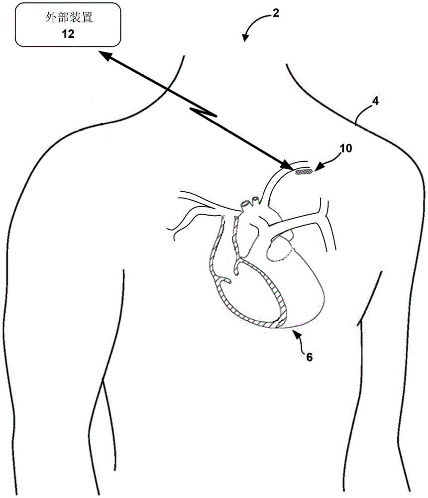
Fig. 1 illustrates an example medical device system 2 incorporating the environment of a patient 4 and a heart 6 in accordance with apparatus and methods described herein, according to some examples. Example techniques may be used with IMD 10, which may be leadless and may communicate wirelessly with external device 12 as illustrated in fig. 1. In some examples, IMD 10 may take the form of a Reveal LINQ available from Medtronic pic, of Dublin, Ireland, Dublin, of Dublin, of Ireland, Dublin, of Dublin, of Ireland, of Ireland, Dublin, of Ireland, Dublin, Ireland, of Ireland, Dublin, of Ireland, of Ireland, Dublin, and of IrelandTMIn the form of an Insertion Cardiac Monitor (ICM). In some examples, IMD 10 may be coupled to one or more leads. In some examples, IMD 10 may be implanted outside of the chest of patient 4 (e.g., subcutaneously in the pectoral location illustrated in fig. 1). Electrodes of IMD 10, e.g., formed on a housing or carried by leads coupled to IMD 10, may be positioned near or within an artery of patient 4. As illustrated in fig. 1, IMD 10 may be positioned near the left subclavian artery of patient 4, but in other examples IMD 10 (e.g., electrodes of IMD 10) may be positioned near any other suitable artery.
External device 12 may be a computing device configured for use in an environment such as a home, clinic, or hospital, and may further be configured to communicate with
IMD 10 via wireless telemetry. For example, the
external device 12 may be coupled to a remote patient monitoring system, such as available from mayonney, inc
In some examples, the
external device 12 may include a programmer, an external monitor, or a consumer device such as a smart phone or tablet. In other examples, the example techniques and systems described herein may be used with external medical devices in addition to or in place of
IMD 10. Such an external medical device may be positioned external to patient 4 (e.g., on the skin of patient 4) and may perform any or all of the functions described herein with respect to
IMD 10.
The medical device system 2 may contain a plurality of electrodes (e.g., for sensing cardiac function of the patient 4). In some examples, the plurality of electrodes may be positioned on a housing of IMD 10. At least two of the plurality of electrodes may detect an arterial impedance signal of the patient 4 that enables processing circuitry of the medical device system 2 to determine an estimated arterial pressure waveform of the patient 4 based on such signals. Although such processing circuitry may be housed within IMD 10 and/or within another medical device of medical device system 2, such as external device 12, for clarity, processing circuitry may be described herein as a component of IMD 10.
The processing circuitry may determine an estimated arterial pressure waveform for the patient based on the arterial impedance signals received from at least two of the plurality of electrodes. In some examples, the technique by which the processing circuitry estimates the morphometry of the estimated arterial pressure waveform of the patient may include filtering the impedance signal to remove content from the impedance signal. For example, the processing circuitry may filter the impedance signal to remove high frequency content (e.g., greater than or equal to about 20 hertz (Hz)), very low frequency content (e.g., less than or equal to about 0.05Hz to about 01.Hz), and/or a DC component of the signal from the signal. In some instances, the processing circuitry may determine the boundaries of one or more arterial pressure cycles, such as by processing an impedance signal or another signal (e.g., an electrocardiogram cardiac signal) within a window timed by a reference (e.g., an R-wave and/or any other suitable reference) associated with the cardiac cycle of the patient 4. Depending on factors such as the distance of IMD 10 from heart 6, the proximity of IMD 10 to the arteries of patient 4, and or the substantial alignment of IMD 10 to the arteries of patient 4, the morphometry of the impedance waveform may be more or less similar to the morphometry of the estimated arterial pressure waveform of patient 4.
For example, the similarity of the morphometry of the impedance waveforms to the estimated arterial pressure waveforms may increase as the distance between IMD 10 and the artery of patient 4 decreases and/or as at least two of the plurality of electrodes are positioned in closer alignment with the longitudinal axis of the artery, which may be attributable to a corresponding decrease in the effect of non-arterial tissue impedance on the impedance signals sensed by the at least two of the plurality of electrodes. Additionally or alternatively, the similarity of the morphometry measurements may increase as the distance between heart 6 and IMD 10 increases, which may be attributable to a corresponding decrease in the effect of impedance fluctuations caused by changes in fluid volume of the Left Ventricle (LV) of heart 6 on the impedance signals sensed by at least two of the plurality of electrodes of IMD 10. Thus, in some examples, positioning IMD 10 near or within an artery of patient 4 and/or relatively far from heart 6 (e.g., within a thoracic region of patient 4) may help enable electrodes of IMD 10 to detect arterial impedance signals that fluctuate substantially in accordance with fluctuations in an estimated arterial pressure waveform of patient 4. In some examples, the housing and/or one or more leads of the IMD of system 2 may provide more than two electrodes, and thus a plurality of associated electrode vectors. In such instances, the processing circuitry of system 2 may analyze the arterial impedance signals received from one or more respective electrode vectors of the plurality of electrode vectors and identify one of the plurality of electrode vectors that provides a suitable arterial impedance signal (e.g., substantially unaffected by non-arterial tissue impedance). The processing circuitry, or in some instances, the clinician may then select the identified electrode vectors for use in determining an estimated arterial pressure waveform for the patient 4.
The estimated arterial pressure waveform may contain a plurality of arterial pressure cycles, each of which may correspond to a different cardiac cycle of a plurality of cardiac cycles of the patient 4. For at least some of the plurality of cardiac cycles of the patient 4, the processing circuitry may determine at least one value corresponding to a natural frequency of a cycle of arterial pressure. For example, the processing circuitry may determine the minimum value of the natural frequency of the corresponding arterial pressure cycle by determining a value of a first natural frequency of a first portion of the corresponding arterial pressure cycle and a value of a second natural frequency of a second portion of the corresponding arterial pressure cycle, the second portion following the first portion of the corresponding arterial pressure cycle.
In some examples, the processing circuitry may determine at least one value of the natural frequency of the estimated arterial pressure waveform of the patient 4 based on an assumption that the instantaneous frequency of the coupled cardiac-aortic system and the decoupled aorta is a segmented time constant, thereby enabling extraction of the value of the natural frequency from the estimated arterial pressure waveform. In some examples, the signal may be passed through a waveform norm-2 (L)2) Minimization methods (e.g., reducing sparse time-frequency representation (STFR) methods to L of periodic signals2Minimization problem) extracts the natural frequency from the arterial pressure. In such instances, the envelope of the eigenmode function ((IMF); its instantaneous frequency can be extracted by applying the adaptive STFR method to the pressure wave) can also be assumed as the time constant of the temporal segment used to distinguish between the coupled heart-aorta system and the decoupled aorta. L for extracting trend and frequency content of input pressure wave (e.g., arterial pressure wave)2The minimization problem can be defined as follows:
and (3) minimizing:
(expression 1)
So that:
a1 cos(ω1T0)|+b1 sin(ω1T0)=a2 cos(ω2T0)(ω2T0),
(equation 1)
a1=a2 cos(ω1T)+b2 sin(ω2T),
(equation 2)
s1(t)=a1 cos(ω1t)+b1 sin(ω1t)
(equation 3)
And s2(t)=a2 cos(ω2t)+b2 sin(ω2t)。
(equation 4)
In this case, the amount of the solvent to be used,
(equation 5)
And c is a constant.
The problem is reduced to a1、a2、c、b1、b2、ω1And ω2And (6) solving. Equations 1 and 2 are the guaranteed time T0The time trend has a linear constraint of linearity, which may be a dicrotic notch of the arterial pressure cycle of the patient 4. In instances in which the processing circuitry determines a value corresponding to a first natural frequency for a first portion of the arterial pressure cycle (e.g., before the dicrotic notch) and a value corresponding to a second natural frequency for a second portion of the arterial pressure cycle (e.g., after the dicrotic notch), the first natural frequency may be represented by ω1And the second natural frequency may be represented by ω2Indicating that the second portion follows the first portion of the corresponding arterial pressure cycle. The above minimization indicates that the arterial pressure wave of the patient 4 may pass through the arterial blood vessel with different frequencies (e.g., ω1And ω2) The different frequencies may correspond to respective ones of the values of the first natural frequency and the values of the second natural frequency in one or more of the examples described herein.
The processing circuitry of medical device system 2 may determine the heart failure state of patient 4 based on the value of the first natural frequency and the value of the second natural frequency, such as based on a comparison of the value of the first natural frequency and the value of the second natural frequency. For example, the processing circuitry may determine, for at least some of the plurality of arterial pressure cycles of the patient 4 corresponding to at least some of the plurality of cardiac cycles of the patient 4, at least one of a difference between the value of the first natural frequency and the value of the second natural frequency or a ratio of the value of the first natural frequency and the value of the second natural frequency and determine the heart failure state of the patient 4 based on the at least one of the difference or the ratio.
In some examples, one of the value of the first natural frequency or the value of the second natural frequency may be more predictive of the heart failure condition of the other pair of patients. For example, a decreasing and/or low (e.g., relative to a baseline) value of the second natural frequency corresponding to a portion of the arterial pressure cycle occurring after the dicrotic notch of the arterial pressure cycle may be an associated physiological phenomenon indicative of disease progression, such as an increasing arterial stiffness and/or hypertension. In such examples, the processing circuitry may assign a weight to at least one of the value of the first natural frequency or the value of the second natural frequency prior to comparing the value of the first natural frequency to the value of the second natural frequency. The weighting assigned by the processing circuitry to the value of the natural frequency of the arterial pressure cycle may be independent of the value of the natural frequency or may be determined by the processing circuitry based at least in part on the value of the natural frequency. For example, the processing circuitry may assign a different weight to values of the natural frequency in a relatively lower range of values than to values of the natural frequency in a relatively higher range of values. In some examples, the clinician may manually modify the values assigned to the one or more natural frequencies by the processing circuitry based on the individual condition or medical history of the patient 4. For example, the clinician may manually modify one or more of the weights assigned by the processing circuitry based on events in the medical history of the patient 4, such as admission to heart failure, medication changes, a history of systolic or diastolic heart failure, or hypertension. In any such instance, the weights assigned to the values of one or more natural frequencies may be stored in a memory of IMD 10 or another device of system 2.
Additionally or alternatively, the processing circuitry may determine the heart failure state of the patient 4 based on a current value of the at least one natural frequency. For example, the processing circuitry may determine at least one current value of a natural frequency of the arterial pressure cycle of the patient 4 for at least some of the plurality of arterial pressure cycles of the patient 4 corresponding to at least some of the plurality of cardiac cycles of the patient 4 and compare the at least one current value of the natural frequency to at least one corresponding baseline value of the natural frequency. The current value may be a single value for the current pressure cycle, or a mean, median, or other representative value of frequency values from multiple pressure cycles during the current time period, such as the current minute, hour, portion of day, or day. The baseline value may be a mean, median, or other representative value determined from the frequency values of the pressure cycles during the past time period. In some such instances, the processing circuitry may determine at least one of the differences between at least one current value of the natural frequency and at least one corresponding baseline value of the natural frequency. The processing circuitry may then determine a heart failure state of the patient 4 based on a comparison of the at least one current value of the natural frequency with at least one corresponding baseline value of the natural frequency.
In any such example, the processing circuitry of medical device system 2 may transmit the determined heart failure state of patient 4 to a remote computer (e.g., external device 12). The processing circuitry may then receive instructions for performing a medical intervention from the remote computer based on the heart failure state of the patient 4 and transmit the instructions for performing a medical intervention to the user interface.
In some examples, the processing circuitry of medical device system 2 determines that the interval of the heart failure state of patient 4 is the same as the interval at which the processing circuitry transmits the heart failure state to the remote computer. In other examples, the processing circuitry may determine the heart failure state of patient 4 more frequently than the processing circuitry transmits the heart failure state to the remote computer. By determining the heart failure state more frequently than transmitting the heart failure state, the accuracy of the techniques for determining the heart failure state may be enhanced by eliminating outlier measurements. For example, the processing circuitry may determine at least one of a difference between a value of the first natural frequency and a value of the second natural frequency, a ratio of a value of the first natural frequency to a value of the second natural frequency, or a difference between at least one current value of the natural frequency and at least one corresponding baseline value of the natural frequency satisfies at least one corresponding threshold only when a certain number or proportion of previous results satisfy the threshold. In other examples, a single event where this difference or ratio meets a threshold may be sufficient for the processing circuitry to determine that a change in the heart failure state of patient 4 has occurred. For the sake of clarity, the difference between the value of the first natural frequency and the value of the second natural frequency, the ratio of the value of the first natural frequency and the value of the second natural frequency or the difference between at least one current value of the natural frequency and at least one corresponding baseline value of the natural frequency may be collectively referred to herein as a "natural frequency metric".
In some instances, a clinician may configure the sensitivity of the processing circuitry to different thresholds at or after implantation of IMD 10, depending on factors such as the individual condition of patient 4. In instances where the technique involves comparing a difference between a current value of the natural frequency and a baseline value of the natural frequency to a corresponding threshold value for each of the first natural frequency and the second natural frequency, the clinician may configure the processing circuitry to be more sensitive to values that satisfy the threshold value associated with the second natural frequency. For example, if the difference between the current value of the second natural frequency and the baseline value of the second natural frequency satisfies the corresponding threshold several times less than required by the difference between the current value of the first natural frequency and the baseline value of the first natural frequency, the processing circuitry may determine that the heart failure state of the patient 4 has changed, e.g., depending on which threshold, if satisfied, may be more predictive of an adverse medical event of the patient 4. As discussed below, several aspects of the operation of IMD 10 may be configured by a clinician to help achieve improved monitoring and clinical results for an individual patient, such as patient 4.
In some examples, IMD 10 may be configured to perform a learning period after implantation into patient 4. During this learning period, the processing circuitry may determine one or more baseline values and one or more thresholds, which the processing circuitry may store in memory of IMD 10 or other devices of medical device system 2. For example, the processing circuitry may determine at least one of a baseline difference between a value of a first natural frequency of the arterial pressure cycle and a value of a second natural frequency of the arterial pressure cycle or a ratio of the value of the first natural frequency to the value of the second natural frequency of the patient 4. Additionally or alternatively, the processing circuitry may determine at least one baseline value of a natural frequency of the arterial pressure cycle of the patient 4, such as a baseline value of a first natural frequency of a first portion of the arterial pressure cycle and/or a baseline value of a second natural frequency of a second portion of the arterial pressure cycle. In some such examples, the processing circuitry may determine the baseline value by averaging or otherwise combining a plurality of differences, ratios, or absolute values of the natural frequency obtained during a plurality of monitoring periods (e.g., a plurality of days). Based on this determined baseline value, the processing circuitry or clinician may determine a corresponding threshold value. The threshold value may be a value of the natural frequency metric that is greater than or less than a corresponding baseline value by a predetermined amount, which is indicative of a heart failure state change of the patient 4.
In any such instance, the processing circuitry may determine the baseline value by determining a mean, median, or other statistical representation of the values collected during training, although the processing circuitry may use other methods of determining the baseline value from the collected values. In some instances, the processing circuitry may reject outliers collected during training before determining a baseline value based on the remaining collected values. In this way, the baseline value of the natural frequency metric may be based on a relatively large set of corresponding past values of the patient 4. In some examples, the processing circuitry may determine a value of the natural frequency of the arterial pressure cycle of the patient 4 based on a relatively small set of values that are compared to a corresponding baseline value, either directly or through comparison to a threshold based on the baseline value. For example, the processing circuitry may determine the value of the natural frequency metric based on a short-term average of a relatively small set of recent values of such differences, ratios, and/or absolute values that occur after the past value of the patient 4 on which the corresponding baseline value is based. Thus, in some examples, the processing circuitry may determine the value of one or more natural frequency metrics by averaging or otherwise combining a set of such values.
Because heart failure conditions may be progressive in nature, the baseline and/or thresholds associated with patient 4 may be updated periodically. For example, IMD 10 may conduct a new learning period monthly, quarterly, annually, or upon expiration of any other suitable time period. The new learning period may generate new values associated with one or more of the baseline and/or threshold values described with respect to the techniques described herein based on the updated heart failure state of patient 4. In other examples, a clinician may program IMD 10 to update such values as needed, such as to track health events experienced by patient 4 that may affect the suitability of such values for one or more aspects of the heart failure state of patient 4.
In addition to or instead of performing a new learning period to determine one or more updated thresholds, the processing circuitry may determine one or more thresholds based on trends in the determined values of one or more of the difference, ratio, and/or absolute value of the natural frequencies of the arterial pressure cycle of the patient 4. Determining one or more thresholds based on such trends may help enable detection of additional aspects of the change in heart failure state of patient 4. Thus, in some examples, the processing circuitry may determine the value natural frequency metric and/or the one or more corresponding thresholds based on fluctuations in the value of the natural frequency metric of the patient 4 occurring across one or more previous predetermined time periods (e.g., across one or more previous monitoring time periods, such as one or more previous days).
In instances where the processing circuitry determines the heart failure state of the patient 4 based on a comparison of at least one of a difference between a value of the first natural frequency and a value of the second natural frequency or a ratio of a value of the first natural frequency and a value of the second natural frequency to at least one of a natural frequency difference threshold or a natural frequency ratio threshold, the natural frequency difference threshold or natural frequency ratio threshold may be based on one or more values of such difference and/or ratio corresponding to one or more previous predetermined time periods. In instances where the processing circuitry determines the heart failure state of the patient 4 based on a comparison of the difference between the current value of the natural frequency and the baseline value and at least one corresponding natural frequency threshold value, the predetermined time period may be a current predetermined time period and the at least one corresponding natural frequency threshold value may be based on one or more corresponding previous values of the natural frequency of the patient 4 corresponding to one or more previous predetermined time periods.
Although example techniques for determining the heart failure state of patient 4 are described herein as parameters based on at least one value of the natural frequency of the arterial pressure cycle, such examples are not intended to be limiting. In some examples, the technique for determining the heart failure state of patient 4 may be based on one or more other physiological parameters indicative of a combination of the heart failure state of patient 4 and the natural frequency of the arterial pressure cycle. Examples of such other parameters, as well as techniques for determining heart failure status based on multiple parameters, are described in U.S. patent application publication No. 2012/0253207 to Sarkar et al and in "Development and validation of comprehensive diagnostic algorithms derived from parameters monitored in an implantable device for identifying patients at risk of heart failure hospitalization in a ambulatory environment (Development and identification of an integrated diagnostic derived from patient monitoring in an ambulatory environment) which are incorporated herein by reference in their entirety.
For example, the processing circuitry of medical device system 2 may determine the heart failure state of patient 4 based on a plurality of physiological parameters including at least one value of the patient's natural frequency and a value of the subcutaneous tissue impedance. In such examples, processing circuitry may determine a value of subcutaneous tissue impedance of patient 4 based on subcutaneous tissue impedance signals received from at least two of the plurality of electrodes of IMD 10. At least two electrodes of the plurality of electrodes of IMD 10 from which processing circuitry receives subcutaneous tissue impedance signals may be the same or different from at least two electrodes from which processing circuitry receives arterial impedance signals.
The processing circuitry may then determine the heart failure state of the patient 4 based on the at least one value of the natural frequency metric and the value of the subcutaneous tissue impedance, such as by using a multivariate algorithm, a bayesian algorithm, or any other suitable machine learning method. In the example of a bayesian approach, the model parameters may be determined from clinical data or may be selected based on empirical assumptions. In some examples, the plurality of physiological parameters may include one or more other physiological parameters indicative of the heart failure state of patient 4 in addition to or in place of subcutaneous tissue impedance, such as augmentation index, reservoir pressure, time to peak pressure, and/or Windkessel parameters (e.g., total arterial compliance, total arterial resistance, and characteristic impedance). In some instances, such other physiological parameters may include other physiological parameters that are more broadly indicative of the health state of patient 4, such as tissue oxygen saturation, pulse transmission time, and/or any other suitable physiological parameter.
In some examples, an example technique for determining a heart failure state of patient 4 based on a plurality of physiological parameters may include one or more aspects of a method for determining a heart failure risk state described by Sarkar et al in U.S. patent application publication No. 2012/0253207. In some such examples, the processing circuitry may determine a heart failure risk level for patient 4, such as a "high", "medium", or "low" risk level. A "high" risk level may be associated with a likelihood that the patient will be hospitalized of about 15% or more. The "low" category may represent a diagnostic assessment in which the likelihood of hospitalization for all patient metrics (e.g., metrics based on multiple physiological parameters) is mostly at a "low" level, which may be associated with a likelihood that patient 4 will require hospitalization of about 5% or less. The "medium" category may contain other metric state combinations not classified as "high" or "low". In some cases, a clinician may evaluate and respond to high and/or medium risk level alerts.
In any such instance, if one or more previous predetermined time periods indicate that the cardiac function is increasingly irregular, the processing circuitry may modify the threshold to provide greater sensitivity to continued fluctuations, such as by raising or lowering the threshold. In this way, the processing circuitry may modify the sensitivity of the technique for determining the heart failure state by taking into account trends in the determined values of the one or more natural frequency metrics of the patient 4, which may further assist in enabling detection of changes in the heart failure state of the patient 4.
Thus, as described above, the operating parameters of IMD 10 may be readily customized to meet the needs of patient 4, such as by setting baselines and/or thresholds based on individual attributes of patient 4, such as a heart failure condition or other medical condition of the patient and/or an existing drug therapy regimen of patient 4. The degree and ease of customizability of IMD 10 may provide a number of benefits. For example, IMD 10 reflects the heart failure condition of patient 4 or the customizability of existing drug regimens to help ensure that patient 4 is prescribed the appropriate therapy, thereby reducing the likelihood of human error in prescribing the therapy. Additionally, in instances where one or more baselines and/or thresholds of patient 4 of circuitry (e.g., of IMD 10) are processed, the time burden on a clinician and/or other medical personnel may be reduced, which may reduce the time required for an office visit and facilitate effective treatment. Further, as discussed above, techniques for using medical device system 2 to determine a heart failure state of patient 4 between visits may help avoid adverse medical events, which may lead to better clinical outcomes, such as improving the quality of life of patient 4 or reducing medical costs.
External device 12 may be a computing device (e.g., for use in a home, clinic, or hospital environment) that communicates with
IMD 10 via wireless telemetry. The
external device 12 may comprise or be coupled to a device such as that available from mayonney, inc
And the like. As an example, the
external device 12 may be a programmer, an external monitor, or a consumer device (e.g., a smartphone). In some examples,
external device 12 may receive data, alerts, patient physiological information, or other information from
IMD 10.
External device 12 may be used to program commands or operating parameters into IMD 10 in order to control its operation (e.g., when configured as a programmer for IMD 10). In some examples, external device 12 may be used to interrogate IMD 10 to retrieve data, including device operating data as well as physiological data accumulated in IMD memory. Such queries may occur automatically according to a schedule and/or may occur in response to remote or local user commands. Programmers, external monitors, and consumer devices are examples of external devices 12 that may be used to interrogate IMD 10. Examples of communication techniques used by IMD 10 and external device 12 include Radio Frequency (RF) telemetry, which may be an RF link established through Bluetooth, Wi-Fi, or Medical Implant Communication Service (MICS). In some examples, external device 12 may include a user interface configured to allow patient 4, a clinician, other medical personnel, another caregiver, or any other user to remotely interact with IMD 10.
Medical device system 2 is an example of a medical device system configured to monitor a heart failure state of patient 4 and facilitate updating a treatment of patient 4 (e.g., for a heart failure condition) as needed between clinician visits. The techniques described herein may be performed by processing circuitry of a device of medical device system 2, such as processing circuitry of IMD 10. Additionally or alternatively, the techniques described herein may be performed in whole or in part by processing circuitry of external device 12 and/or by processing circuitry of one or more other implanted or external devices or servers (not shown). Examples of one or more other implantable or external devices may include an implantable multi-channel cardiac pacemaker, ICD, IPG, leadless (e.g., intracardiac) pacemaker, extravascular pacemaker and/or ICD, or other IMDs configured to deliver CRT to heart 6 or a combination of such IMDs, an external monitor, or a drug pump.
The communication circuitry of each of the devices of medical device system 2 (e.g., IMD 10 and external device 12) may enable the devices to communicate with each other. Additionally, although one or more sensors (e.g., electrodes) are described herein as being positioned on a housing of IMD 10, in other examples, such sensors may be positioned on a housing of another device implanted within or external to patient 4. In such examples, one or more of the other devices may include processing circuitry configured to receive signals from electrodes or other sensors on the respective device and/or communication circuitry configured to transmit signals from the electrodes or other sensors to another device (e.g., external device 12) or a server.
Fig. 2-4B illustrate various aspects and example arrangements of IMD 10 of fig. 1. For example, fig. 2 conceptually illustrates an example physical configuration of IMD 10. Fig. 3 is a block diagram illustrating an example functional configuration of IMD 10. Fig. 4A and 4B illustrate additional views of example physical and functional configurations of IMD 10. It should be appreciated that any of the examples of IMD 10 described below with respect to fig. 2-4B may be used to implement the techniques described herein for determining a heart failure state of patient 4.
Fig. 2 is a conceptual diagram illustrating an example configuration of IMD 10 of fig. 1. In the example shown in fig. 2, IMD 10 may include a leadless, subcutaneously implantable monitoring device having a housing 14, a proximal electrode 16A, and a distal electrode 16B. Housing 14 encloses electronic circuitry positioned within IMD 10 and protects the circuitry contained therein from fluids such as body fluids. In some examples, 14 may include a first major surface 18, a second major surface 20, a proximal end 22, and a distal end 24. Proximal electrode 16A and distal electrode 16B may be positioned near respective proximal and distal ends 22, 24 of IMD 10 such that the spacing between proximal and distal electrodes 16A, 16B may range from about 30-55mm, about 35-55mm, or about 40-55mm, or more typically about 25-60 mm. In some examples, IMD 10 may include one or more additional electrodes and/or one or more other sensors (not shown) that may be positioned on one or both of major surfaces 18, 20 of IMD 10. In any such example, an electrical feedthrough may provide an electrical connection of the electrodes 16A, 16B or other sensor to circuitry within the housing 14.
In the example shown in fig. 2, IMD 10 is defined by a length L, a width W, and a thickness or depth D. In this example, IMD 10 is in the form of an elongated rectangular prism, wherein length L is substantially greater than width W, and wherein width W is greater than depth D. However, other configurations of IMD 10 are contemplated, such as those in which the relative proportions of length L, width W, and depth D are different from those shown and described in fig. 2. In some examples, the geometry of IMD 10, such as width W being greater than depth D, may be selected to allow IMD 10 to be inserted under a patient's skin using minimally invasive surgery and maintained in a desired orientation during insertion. In addition, IMD 10 may include radial asymmetry along the longitudinal axis of IMD 10 (e.g., a rectangular shape), which may help maintain the device in a desired orientation after implantation.
In general, the length L of IMD 10 may be about 20-30mm, about 40-60mm, or about 45-60 mm. In some examples, the width W of first major surface 18 may range from about 3-10mm, and may be any single width or range of widths between about 3-10 mm. In some examples, depth D of IMD 10 may range from about 2-9 mm. In other examples, depth D of IMD 10 may range from about 2-5mm, and may be any single depth or range of depths from about 2-9 mm. In any such example, IMD 10 is sufficiently compact to be implanted within a subcutaneous space in a pectoral region of patient 4.
The geometry and size of IMD 10 may be designed for ease of implantation and patient comfort. For example, IMD 10 may have a 3 cubic centimeter (cm)3) Or less, 1.5cm3Or a smaller volume or any volume therebetween. As illustrated in fig. 2, proximal end 22 and distal end 24 may be rounded, which may reduce discomfort and/or irritation to surrounding tissue when IMD 10 is implanted under the skin of patient 4. An example of a configuration of IMD 10 that includes instruments and methods for inserting IMD 10 is described in U.S. patent application publication No. 2014/0276928 to Vanderpool et al. An exemplary configuration of IMD 10 is also described in U.S. patent No. 9,675,270 to Sarkar.
In some examples, IMD 10 may be configured for implantation within patient 4 such that first major surface 18 of IMD 10 faces outwardly toward the skin and second major surface 20 faces inwardly toward muscle tissue of patient 4 when IMD 10 is inserted within patient 4. First major surface 18 and second major surface 20 may face in a direction along the sagittal axis of patient 4, as illustrated in fig. 1, and this orientation may be maintained due to the size of IMD 10 when implanted. Additionally or alternatively, IMD 10 may be configured for implantation within patient 4 in one or more other orientations relative to one or more anatomical landmarks of patient 4.
In the example shown in fig. 2,
proximal end 22 of
IMD 10 includes a
head assembly 32 with one or more of an
integrated antenna 26, anti-migration protrusions 34, and suture holes 36. The
integrated antenna 26 is positioned on the same major surface (e.g., first major surface 18) as the
electrode 16A and may be an integral part of the
head assembly 32. In other examples, integrated
antenna 26 may be formed on a major surface opposite
electrode 16A, or may be incorporated within housing 14 of
IMD 10. The
antenna 26 may be configured to transmit or receive electromagnetic signals for communication. For example, the
antenna 26 may be configured to communicate via inductive coupling, electromagnetic coupling, tissue conductance, Near Field Communication (NFC), Radio Frequency Identification (RFID), or the like,
Wi-Fi, or other proprietary or non-proprietary wireless telemetry communication scheme, transmits signals to and receives signals from a programmer.
Antenna 26 may be coupled to communication circuitry of
IMD 10 that may drive
antenna 26 to transmit signals to
external device 12.
Antenna 26 may transmit signals received from
external device 12 to processing circuitry of
IMD 10 via communication circuitry.
IMD 10 may include several features for holding IMD 10 in place once subcutaneously implanted within patient 4. For example, as shown in fig. 2, the housing 14 may include an anti-migration protrusion 34 positioned near the integrated antenna 26. Anti-migration projections 34 may include a plurality of bumps or projections extending away from first major surface 18 and may reduce or prevent movement of IMD 10 after implantation within patient 4. In other examples, the anti-migration projections 34 may be positioned on a major surface opposite the proximal electrode 16A and/or the integrated antenna 26. In addition to or in lieu of anti-migration projections 34, a portion of housing 14 (e.g., head assembly 32) may define suture holes 36 that may enable a clinician to suture IMD 10 to patient tissue to reduce or prevent movement of IMD 10 after implantation within patient 4. In the example of fig. 2, the suture hole 36 is defined by a portion of the head assembly 32 located near the proximal electrode 16A. In some examples, header assembly 32 may comprise a molded header assembly made of a polymeric material, which may be integral with or separable from a main portion of IMD 10.
In the example shown in fig. 2, proximal electrode 16A is in close proximity to proximal end 22, and distal electrode 16B is in close proximity to distal end 24 of IMD 10. In this example, the distal electrode 16B is not limited to a flat outwardly facing surface, but may extend from the first major surface 18 around the rounded edge 28 or end surface 30 and into the second major surface 20 in a three-dimensional curved configuration. As illustrated, the proximal electrode 16A is positioned on the first major surface 18 and is substantially flat and faces outwardly. However, in other examples not shown herein, both the proximal electrode 16A and the distal electrode 16B may be configured like the proximal electrode 16A shown in fig. 2, or both may be configured like the distal electrode 16B shown in fig. 2. Any of the electrodes 16A, 16B may be formed of a biocompatible conductive material. For example, any of the electrodes 16A, 16B may be formed from any of stainless steel, titanium, platinum, iridium, or alloys thereof. In addition, the electrodes of IMD 10 may be coated with materials such as titanium nitride or fractal titanium nitride, although other suitable materials and coatings for such electrodes may be used.
Proximal electrode 16A and distal electrode 16B may be used to sense impedance signals (e.g., arterial impedance signals and/or tissue impedance signals) when IMD 10 is subcutaneously implanted within patient 4. In the techniques described herein, processing circuitry of IMD 10 may determine values for at least one natural frequency metric based on the arterial impedance signal. In some examples, electrodes 16A and 16B or additional electrodes of IMD 10 may be used to sense cardiac electrogram signals when IMD 10 is subcutaneously implanted within patient 4. In such examples, the processing circuitry may determine whether the electrogram signals of the heart of the patient 4 indicate an arrhythmia (e.g., the presence or absence of atrial fibrillation and the ventricular rate during atrial fibrillation) or other abnormality that the processing circuitry may assess when determining whether the cardiac function of the patient 4 has changed. Additionally or alternatively, the processing circuitry may determine a plurality of cardiac cycles of the electrocardiogram of the heart and associate at least some of the plurality of cardiac cycles with corresponding ones of a plurality of arterial pressure cycles determined based on the estimated arterial pressure waveform of the patient 4. The impedance signals and/or electrogram signals may be stored in a memory of IMD 10, and data derived from the impedance signals and/or electrogram signals may be transmitted to another medical device, such as external device 12, via integrated antenna 26.
In some examples, IMD 10 may include one or more additional sensors, such as one or more accelerometers and/or pressure sensors (not shown). Such an accelerometer may be a 3D accelerometer configured to generate signals indicative of one or more types of movement of the patient, such as the patient's overall body movement (e.g., activity), patient posture, movement and/or sounds associated with the beating, breathing rate, or other of the heart 6. Such a pressure sensor may be configured to generate a signal indicative of pressure variations associated with the beating of the heart 6, on the basis of which the processing circuitry may determine the heart rate of the patient 4. In an example technique for determining the heart failure state of the patient 4, as in a technique in which the processing circuitry determines the heart failure state of the patient 4 based on a combination of one or more other physiological parameters and the natural frequency of the arterial pressure cycle, the processing circuitry may use values of the physiological parameters determined based on signals from one or more accelerometers and/or pressure sensors.
In some instances, the processing circuitry may determine values of the one or more natural frequency metrics for respective pre-scheduled time periods throughout the day and night, which may enable the processing circuitry to distinguish values of the natural frequency metrics that occur when the patient 4 is substantially inactive (e.g., asleep) from values of the natural frequency metrics that occur when the patient 4 is active (e.g., awake). Distinguishing the value of the natural frequency metric that occurs when the patient 4 is asleep from such value that occurs when the patient 4 is awake may help the medical device system 2 take into account the circadian rhythm of the patient 4 in determining the heart failure state of the patient 4, as discussed further below with respect to fig. 3. Thus, in some examples, the processing circuitry may determine, based on one or more signals received from one or more accelerometers, pressure sensors, and/or electrodes 16A, 16B, whether at least one of an activity level, posture, heart rate, or respiration rate, or a certain time of day, of the patient 4 indicates that the patient 4 is substantially inactive (e.g., asleep) or active (e.g., awake).
In some examples, the processing circuitry may determine the value of the natural frequency metric based on at least two values of the natural frequency metric for at least two corresponding arterial pressure cycles of the patient 4. For example, in example techniques in which the processing circuitry determines the heart failure state of the patient 4 based on a difference between a value of the first natural frequency and a value of the second natural frequency or a ratio of the value of the first natural frequency to a peak value of the second natural frequency, the processing circuitry may determine one or both of the value of the first natural frequency or the value of the second natural frequency by determining a corresponding representative value of the first natural frequency or a value of the second natural frequency based on a corresponding plurality of values of the first natural frequency or the value of the second natural frequency. Similarly, in example techniques in which the processing circuitry determines the heart failure state of the patient 4 based on a comparison of at least one current value of the natural frequency and at least one corresponding baseline value of the natural frequency, the processing circuitry may determine one or both of the at least one current value and the at least one corresponding baseline value of the natural frequency by determining at least one corresponding representative current value of the natural frequency based on a corresponding plurality of current values and/or baseline values of the natural frequency.
In any such example, the processing circuitry may determine each of the plurality of values of the natural frequency metric by intermittently sampling the value of the natural frequency metric during a certain time period. For example, the processing circuitry may determine the value of the natural frequency metric at 3 minute intervals over a 30 second period, each interval exceeding ten measurement cycles for a total duration of 30 minutes, although any other suitable interval, number of cycles, or period may be used. Then, the processing circuitry may determine a representative value for the natural frequency metric based on the values of the natural frequency metric collected during the time period. In some instances, the processing circuitry may reject any outliers of the natural frequency metric, which may help improve the accuracy of determining the heart failure state of the patient 4. The processing circuitry may average the collected measurements and subtract any rejected outliers to determine a representative value, although any other suitable data analysis method may be used.
Although processing circuitry of IMD 10 is described above as being configured to receive signals from electrodes 16A, 16B and/or one or more other sensors (e.g., one or more accelerometers or one or more pressure sensors) and determine values of one or more physiological parameters of patient 4 based on such signals, any of the steps described herein that are performed by processing circuitry of IMD 10 may be performed by processing circuitry of one or more devices. For example, processing circuitry of external device 12 or any other suitable implantable or external device or server may be configured to receive signals from one or more accelerometers, one or more pressure sensors, and/or electrodes 16A, 16B, such as through communication circuitry of IMD 10.
Fig. 3 is a functional block diagram illustrating an example configuration of IMD 10 of fig. 1 and 2. As shown in fig. 3, IMD 10 includes processing circuitry 50, sensing circuitry 52, communication circuitry 54, memory 56, sensors 58, and switching circuitry 60, in addition to the previously described electrodes 16A, 16B, one or more of which may be disposed within housing 14 of IMD 10. In some examples, memory 56 includes computer readable instructions that, when executed by processing circuitry 50, cause IMD 10 and processing circuitry 50 to perform various functions attributed herein to IMD 10 and processing circuitry 50. The memory 56 may comprise any volatile, non-volatile, magnetic, optical, or electrical media, such as Random Access Memory (RAM), read-only memory (ROM), non-volatile RAM (NVRAM), Electrically Erasable Programmable ROM (EEPROM), flash memory, or any other digital media.
The processing circuitry 50 may comprise fixed function circuitry and/or programmable processing circuitry. The processing circuitry 50 may include any one or more of the following: a microprocessor, controller, Digital Signal Processor (DSP), Application Specific Integrated Circuit (ASIC), Field Programmable Gate Array (FPGA), or equivalent discrete or analog logic circuitry. In some examples, processing circuitry 50 may include multiple components such as any combination of one or more microprocessors, one or more controllers, one or more DSPs, one or more ASICs, or one or more FPGAs, as well as other discrete or integrated logic circuitry. The functionality attributed herein to processing circuitry 50 may be embodied as software, firmware, hardware, or any combination thereof.
In some examples, timing and/or control aspects of processing circuitry 50 may include dedicated hardware circuitry, such as an ASIC, separate from other aspects of processing circuitry 50, such as a microprocessor or a software module executed by a component of processing circuitry 50 (e.g., a microprocessor or an ASIC). In some examples, the timing and/or control aspects of the processing circuitry 50 may be configured to associate a current value of the natural frequency of the arterial pressure cycle with a particular time of day, such as a daytime time or a nighttime time, in order to enable the processing circuitry 50 to take into account the circadian rhythm of the patient 4 when determining the heart failure state of the patient 4. For example, the arterial pressure value and/or heart rate of the patient 4 may generally decrease when the patient 4 is asleep (e.g., nighttime) and may increase when the patient 4 is awake (e.g., daytime).
In some such examples, IMD 10 may be configured to use a different (e.g., lower) baseline value and/or threshold for the natural frequency metric when patient 4 may be asleep, rather than when patient 4 may be awake. For example, the processing circuitry may treat the daytime and nighttime values of the natural frequency metric as separate, independent parameters with separate associated baselines and/or thresholds. In some examples in which IMD 10 includes one or more accelerometers, processing circuitry 50 may cross-reference the time of day indicated by timing and/or control aspects of processing circuitry 50 with the accelerometer data, such as to confirm whether patient 4 is asleep or awake as predicted based on the time of day. In this manner, the timing and/or control aspects of processing circuitry 50 may enhance the ability of IMD 10 to accurately determine the heart failure state of patient 4.
The memory 56 may store determined values for one or more natural frequency metrics and/or one or more intervals or time periods of the patient 4 from which the processing circuitry 50 may determine the values for one or more natural frequency metrics in the stored measurements/intervals 62. Memory 56 may also store stored baselines and/or thresholds that processing circuitry 50 in table 64 may determine during a learning period of IMD 10. In some examples, the processing circuitry may determine the intrinsic frequency difference or the ratio threshold based on a determined baseline difference between a baseline value of a first intrinsic frequency of the arterial pressure cycle of the patient 4 and a baseline value of a second intrinsic frequency of the arterial pressure cycle.
For example, processing circuitry 50 may receive at least one baseline arterial impedance signal from an electrode (e.g., electrodes 16A, 16B) of IMD 10. The processing circuitry 50 may then determine a baseline arterial pressure waveform based on the arterial impedance signal and determine a particular baseline value for a first natural frequency for a first portion of an arterial pressure cycle and a particular baseline value for a second natural frequency for a second portion of the arterial pressure cycle, the second portion following the first portion, of the arterial pressure cycle for the patient 4 based on the baseline arterial pressure waveform. The processing circuitry 50 may then determine at least one of a baseline difference between the value of the first natural frequency and the value of the second natural frequency or a baseline ratio of the value of the first natural frequency to the value of the second natural frequency based on the baseline value of the first natural frequency and the baseline value of the second natural frequency.
In instances where the processing circuitry 50 determines the heart failure state of the patient 4 based on the difference between the current value of the natural frequency and the baseline value of the natural frequency, the processing circuitry 50 may similarly determine one or more of the baseline and/or threshold values. For example, the processing circuitry 50 may determine the patient-specific baseline value for the natural frequency by: receive a baseline arterial impedance signal from sensor 58 (e.g., from at least two electrodes of IMD 10), determine a baseline arterial pressure waveform based on the arterial impedance signal, and determine a patient-specific value for a baseline natural frequency based on the baseline arterial pressure waveform. In any such instance, table 64 may contain preprogrammed baseline values and/or thresholds that the clinician may select for patient 4 during setup of IMD 10 or manually input based on the clinician's assessment of patient 4.
The sensing circuitry 52 and communication circuitry 54 may be selectively coupled to the electrodes 16A, 16B by switching circuitry 60 as controlled by the processing circuitry 50. Sensing circuitry 52 may monitor the signals from the electrodes 16A, 16B so that the monitoring processing circuitry 50 may determine the arterial impedance of the patient 4 from which the estimated arterial pressure waveform of the patient 4 and/or the values of one or more natural frequency measures of the patient 4 are determined. In some examples in which IMD 10 includes one or more accelerometers and/or pressure sensors, sensing circuitry 52 may also monitor signals from sensors 58, which may include such accelerometers and/or pressure sensors. In some examples, the sensing circuitry 52 may include circuitry for filtering and amplifying signals received from one or more of the electrodes 16A, 16B and/or other sensors 58, such as by filtering arterial impedance signals received from the electrodes 16A, 16B to enable the processing circuitry 50 to identify one or more components of the arterial impedance signals that vary with arterial pressure, so that a measure of the natural frequency of the estimated arterial pressure waveform may be derived from these components.
In some examples, the sensing circuitry 52 and/or the processing circuitry 50 may include rectifiers, filters, and/or amplifiers, sense amplifiers, comparators, and/or analog-to-digital converters. Upon receiving signals from the electrodes 16A, 16B and/or other sensors 58 through the sensing circuitry 52, the processing circuitry 50 may determine, for at least some of the plurality of cardiac cycles of the patient 4, at least one value of a natural frequency of a corresponding one of the plurality of arterial pressure cycles of the estimated arterial pressure waveform of the patient 4. The processing circuitry 50 may then determine the heart failure state of the patient 4 based on at least one value of the natural frequency, such as based on a difference between a value of the first natural frequency and a value of the second natural frequency, a ratio of a value of the first natural frequency to a value of the second natural frequency, or a difference between at least one current value of the natural frequency and at least one corresponding baseline value. For example, the processing circuitry 50 may determine the heart failure state of the patient 4 based on whether this difference or ratio satisfies the corresponding natural frequency difference threshold, natural frequency ratio threshold, or natural frequency threshold stored in the table 64.
The
communication circuitry 54 may include any suitable hardware, firmware, software, or any combination thereof for communicating with another device, such as the
external device 12, or another medical device or sensor, such as a pressure sensing device. Under control of the
processing circuitry 50, the
communication circuitry 54 may receive downlink telemetry from the
external device 12 or another device and transmit uplink telemetry thereto by way of an internal or external antenna, such as
antenna 26. In some examples, the
communication circuitry 54 may communicate with the
external device 12. In addition, the
processing circuitry 50 may communicate via external devices (e.g., external device 12) and metontrin as developed by metontrin corporation of dublin, ireland
A computer network such as a network communicates with networked computing devices.
A clinician or other user may retrieve data from IMD 10 using external device 12 or by using another local or networked computing device configured to communicate with processing circuitry 50 through communication circuitry 54. The clinician may also program parameters of IMD 10 using external device 12 or another local or networked computing device. In some instances, a clinician may select one or more baseline values and/or thresholds associated with one or more natural frequency metrics, a time of day at which the patient 4 is expected to be awake or asleep, a predetermined time period, a number of measurements to be completed during a certain time period, or other parameters of the IMD 10.
One or more components of IMD 10 may be coupled to a power source, which may include a rechargeable or non-rechargeable battery positioned within housing 14 of IMD 10. Non-rechargeable batteries may be selected to last for several years, while rechargeable batteries may be inductively charged from an external device, e.g., on a daily or weekly basis.
Fig. 4A and 4B illustrate two additional example IMDs that may be substantially similar to IMD 10 of fig. 1-3, but may include one or more additional functions. The components of fig. 4A and 4B may not necessarily be drawn to scale, but may be exaggerated to show details. Fig. 4A is a block diagram of a top view of an example configuration of IMD 10A. Fig. 4B is a block diagram of a side view of an example IMD 10B that may include an insulating layer as described below.
Fig. 4A is a conceptual diagram illustrating another example IMD 10 that may be substantially similar to IMD 10A of fig. 1. In addition to the components shown in fig. 1-3, the example of IMD 10 shown in fig. 4A may include a body portion 70 and an attachment plate 72. Attachment plate 72 may be configured to mechanically couple head 32 to body portion 70 of IMD 10A. Body portion 70 of IMD 10A may be configured to house one or more of the internal components of IMD 10 illustrated in fig. 3, such as one or more of processing circuitry 50, sensing circuitry 52, communication circuitry 54, memory 56, and/or internal components of sensor 58. In some examples, the body portion 70 may be formed from one or more of titanium, ceramic, or any other suitable biocompatible material.
Fig. 4B is a conceptual diagram illustrating an example IMD 10B that may include components substantially similar to IMD 10 of fig. 1. In addition to the components shown in fig. 1-3, the example of IMD 10B shown in fig. 4B may also include a wafer level insulating cover 74, which may help insulate electrical signals communicated between electrodes 16A, 16B on housing 14B and processing circuitry 50. In some examples, insulative cover 74 may be positioned over open housing 14 to form a housing for the components of IMD 10B. One or more components of IMD 10B (e.g., antenna 26, processing circuitry 50, sensing circuitry 52, and/or communication circuitry 54) may be formed on the bottom side of insulative cover 74, such as by using flip-chip technology. The insulating cover 74 may be flipped over onto the housing 14B. When flipped over and placed onto housing 14B, the components of IMD 10B formed on the bottom side of insulative cover 74 may be positioned in gap 78 defined by housing 14B. The housing 14B may be formed of titanium or any other suitable material (e.g., a biocompatible material) and may have a thickness of about 200 microns to about 500 microns. These materials and dimensions are examples only, and other materials and other thicknesses are possible for the devices of the present disclosure.
Fig. 5 is a functional block diagram illustrating an example system including an access point 90, a network 92, an external computing device such as a server 94, and one or more other computing devices 100A-100N that may be coupled to IMD 10, external device 12, and external device 12 via network 92. In this example, IMD 10 may use communication circuitry 54 to communicate with external device 12 over a first wireless connection and to communicate with access point 90 over a second wireless connection. In the example of fig. 5, the access point 90, the external device 12, the server 94, and the computing devices 100A-100N are interconnected and may communicate with one another over the network 92.
Access point 90 may include devices that connect to network 92 through any of a variety of connections, such as a telephone dial-up, Digital Subscriber Line (DSL), or cable modem connection. In other examples, access point 90 may be coupled to network 92 through different forms of connection, including wired or wireless connection. In some instances, the access point 90 may be a user device, such as a tablet or smartphone, that may be co-located with the patient. As discussed above, IMD 10 may be configured to transmit data such as current values and heart failure status to external device 12. Additionally, access point 90 may query IMD 10, such as periodically or in response to a command from the patient or network 92, to retrieve the current value of the heart failure state as determined by processing circuitry 50 of IMD 10 or other operating data or patient data from IMD 10. The access point 90 may then transmit the retrieved data to the server 94 via the network 92.
In some cases,
server 94 may be configured to provide a secure storage site for data that has been collected from
IMD 10 and/or
external device 12. In some cases,
server 94 may assemble data on web pages via computing devices 100A-100NOr other documentation for review by a trained professional, such as a clinician. One or more aspects of the illustrated system of fig. 5 may be implemented with Medtronic, which may be similar to that developed by Medtronic corporation of dublin, ireland
General network technology and functionality provided by the network.
In some examples, one or more of computing devices 100A-100N (e.g., device 100A) may be a tablet computer or other smart device located with a clinician or other medical or caregiver through which such user may program, receive alerts from, and/or query IMD 10. For example, the user may visit the determined values of one or more natural frequency metrics of patient 4, as when patient 4 is between clinical visits or family visits, and/or other information associated with the heart failure state of patient 4 by device 100A to check the heart failure state of patient 4 as desired. In some instances, the user may enter instructions for medical intervention of patient 4 into app in device 100A, such as based on the heart failure state of patient 4 determined by IMD 10 and/or other patient data known to the user. The apparatus 100A may then transmit instructions for performing the medical intervention to another of the computing apparatuses 100A-100N located with the patient 4 or another caregiver to the patient 4 (e.g., the apparatus 100B). For example, such instructions for performing a medical intervention may include instructions for changing a drug dosage, timing or selection, for scheduling an visit with a user, or for seeking medical attention. In further examples, apparatus 100B may alert patient 4 based on the health state of patient 4 determined by IMD 10, which may enable patient 4 to actively seek medical attention prior to receiving instructions for performing a medical intervention. In some examples, the alert generated by device 100B may include an updated diagnosis of one or more health conditions, such as a heart failure condition. For example, the alert may comprise a diagnosis that the heart failure condition of patient 4 has progressed from a first type of heart failure condition to a second type of heart failure condition. In this way, patient 4 may be authorized to take action as needed to address his or her heart failure state, which may help improve the clinical outcome of patient 4.
Fig. 6-9 are flow diagrams illustrating various techniques related to determining a heart failure state of a patient based on at least one value of a natural frequency metric of an arterial pressure cycle corresponding to a cardiac cycle of the patient and transmitting instructions to a user interface for performing a medical intervention. As described herein, the illustrated techniques of fig. 6-9 may be employed using one or more components of the medical device system 2, which have been described above with respect to fig. 1-5. Although described as being performed by processing circuitry 50 of IMD 10 for simplicity, the techniques of fig. 6-9 may be performed in whole or in part by processing circuitry and memory of other devices of medical device system 2 as described herein. For example, in some instances, one or more devices (e.g., external device 12 or other external devices or servers) or users such as clinicians or other medical personnel may perform one or more of the following steps attributed to processing circuitry 50 of IMD 10.
Fig. 6 is a flow chart illustrating a method for determining, by processing circuitry of medical device system 2 (e.g., processing circuitry 50 of IMD 10), a heart failure state of patient 4 based on at least one value of a natural frequency of at least some of the plurality of arterial pressure cycles corresponding to at least some of the plurality of cardiac cycles of patient 4. The natural frequency of the arterial pressure cycle may be, for example, a value corresponding to a dominant frequency of a portion of the arterial pressure cycle around which the instantaneous frequency of the portion of the arterial pressure cycle oscillates (e.g., during a cardiac cycle). According to the example of fig. 6, processing circuitry 50 determines an estimated arterial pressure waveform for patient 4 based on arterial impedance signals received from at least two electrodes (e.g., electrodes 16A, 16B) of a plurality of electrodes of IMD 10 (110). The estimated arterial pressure waveform of the patient 4 comprises a plurality of arterial pressure cycles, and each arterial pressure cycle of the plurality of arterial pressure cycles corresponds to a different cardiac cycle of a plurality of cardiac cycles of the patient 4.
After determining the estimated arterial pressure waveform of the patient 4, the processing circuitry 50 then determines at least one value of the natural frequency of the corresponding arterial pressure cycle for at least some of the plurality of cardiac cycles of the patient 4 (112). In some examples, process 50 may determine at least one value of the natural frequency by determining a representative value of the natural frequency based on at least two values of the natural frequency of at least two corresponding arterial pressure cycles. Processing circuitry 50 then determines a heart failure state of patient 4 based on at least one value of the natural frequency (114). For example, the processing circuitry 50 may compare at least one value of the natural frequency to at least one natural frequency threshold and determine a heart failure state of the patient based on the comparison. In some such examples, the plurality of arterial pressure cycles of the estimated arterial pressure waveform of patient 4 may include at least one current arterial pressure cycle and at least one previous arterial pressure cycle.
In some examples, the processing circuitry 50 may periodically determine an updated value of the natural frequency threshold based on at least one value of the natural frequency of at least one previous arterial pressure cycle, which may enable the processing circuitry 50 to track values of the natural frequency over a plurality of predetermined time periods (e.g., days). For example, if the processing circuitry 50 determines that the value of the natural frequency tends to rise or fall within one or more past predetermined time periods, the processing circuitry 50 may update the natural frequency threshold by modifying the natural frequency threshold. For example, if the value of the natural frequency tends to decrease, the processing circuitry 50 may raise the natural frequency threshold, thereby increasing the significance of any further decrease in the value of the natural frequency that may occur after a predetermined period of time.
In some examples, the processing circuitry 50 may be configured to apply the accumulation sum technique to determine a value of the patient parameter, such as a natural frequency, a value of a relationship between the first natural frequency and the second natural frequency (e.g., a difference or a ratio), or a value of another patient parameter to determine whether a trend of the patient parameter indicates that the health condition of the patient is continuously deteriorating. In some such examples, the processing circuitry 50 may adjust the corresponding baseline value of the patient parameter over time based on a long-term trend of the patient parameter determined over one or more previous monitoring time periods, and compare the current value of the patient parameter to the corresponding adjusted baseline value. Examples of techniques and accumulation of trends in monitored patent parameters over time are described in Stadler et al, entitled "Method and apparatus for detecting changes in intra-thoracic electrical impedance" (Method and apparatus for detecting change in intra-thoracic electrical impedance) "and in U.S. patent No. 7,986,994 issued 7/26.2011. U.S. patent No. 7,986,994 to Stadler et al.
The processing circuitry 50 may then determine a current index value for the patient parameter based on a comparison of the current value of the patient parameter to the corresponding adjusted baseline value. The index value for the patient parameter may be an accumulation of the difference between the current value of the patient parameter and the corresponding adjusted baseline value over one or more previous monitoring time periods. For example, the processing circuitry 50 may adjust the index value up or down based on the difference between the current value of the patient parameter and the corresponding adjusted baseline value. The processing circuitry 50 may then compare the current index value to one or more thresholds associated with deviations in the patient parameters that may indicate a trend of an ongoing deterioration in the health condition of the patient 4 (e.g., large and/or long-term deviations in a direction indicating an ongoing deterioration in the health condition). If the current index value meets one or more of the thresholds, the processing circuitry 50 may transmit an alert to a device located with the patient 4 or caregiver (e.g., the external device 12) and/or a computing device located with the clinician. If the current index value does not satisfy one or more of the thresholds, the processing circuitry 50 may not transmit an alert and may continue to adjust the index value as appropriate during one or more subsequent monitoring time periods. For example, if there is a deviation from the trend, processing circuitry 50 may continue to adjust the index value upward until the value satisfies one or more thresholds. In this manner, the medical device system 2 may enable monitoring trends in patient parameters to determine whether the health of the patient 4 is continually deteriorating or improving.
The processing circuitry 50 may repeat blocks 110-114 to periodically determine an updated heart failure state for the patient 4, such as daily, weekly, monthly, yearly, or at any other suitable time period. In some examples, the heart failure state of patient 4 may indicate the likelihood that patient 4 may experience an adverse medical event, such as a relapse of symptoms, acute heart failure decompensation, or other adverse medical event that may require medical intervention, such as hospitalization, for a certain period of time. In some examples, the natural frequency threshold or the natural frequency difference threshold associated with the change in the heart failure state of patient 4 may be associated with an interval at which processing circuitry 50 periodically determines an updated heart failure state of patient 4. For example, a threshold associated with a relatively short (e.g., daily or weekly) time period may be higher than a threshold associated with a relatively long (e.g., monthly or yearly) time period. In some such examples, a gradual change in the value of the intrinsic frequency difference or ratio of patient 4 occurring over a longer period of time may indicate a change in the heart failure state of patient 4, while the same change occurring over a shorter period of time may not necessarily indicate a change in the heart failure state of patient 4. For example, such gradual changes may indicate a long-term worsening or improvement in the heart failure condition of patient 4. In this manner, the techniques described herein may be adapted to periodically determine the heart failure state of patient 4 at one or more suitable intervals.
The processing circuitry then transmits the health status of the patient 4 to a remote computer, such as an external device 12 (116). In some examples, the processing circuitry 50 may transmit the heart failure state of the patient 4 to a remote computer each time the processing circuitry 50 determines the heart failure state of the patient 4. In other examples, processing circuitry 50 may transmit the heart failure state of patient 4 to the remote computer less frequently, such as weekly or at any other suitable interval.
Fig. 7 is a flowchart illustrating an example technique for determining a heart failure state of patient 4 by processing circuitry of medical device system 2 (e.g., processing circuitry 50 of IMD 10) based on a comparison of a value of a first natural frequency of an arterial pressure cycle of patient 4 for a first value and a value of a second natural frequency of a second portion of the arterial pressure cycle of patient 4. In some examples, fig. 7 may be an example of the technique of fig. 6. Accordingly, one or more aspects of the example technique illustrated in fig. 7 may be substantially similar to one or more aspects of the example technique illustrated in fig. 6. According to the example of fig. 7, processing circuitry 50 determines an estimated arterial pressure waveform for patient 4 based on arterial impedance signals received from at least two electrodes (e.g., electrodes 16A, 16B) of a plurality of electrodes of IMD 10 substantially as discussed above with respect to fig. 6 (120). The estimated arterial pressure waveform of the patient 4 comprises a plurality of arterial pressure cycles, and each arterial pressure cycle of the plurality of arterial pressure cycles corresponds to a different cardiac cycle of a plurality of cardiac cycles of the patient 4.
For example, processing circuitry 50 may determine at least one value of a natural frequency of a corresponding arterial pressure cycle by determining a value of a first natural frequency of a first portion of the corresponding arterial pressure cycle (122) and determining a value of a second natural frequency of a second portion of the corresponding arterial pressure cycle (124), the second portion following the first portion of the corresponding arterial pressure cycle. In some examples, the first portion of the corresponding arterial pressure cycle occurs before the dicrotic notch of the corresponding arterial pressure cycle and the second portion of the corresponding arterial pressure cycle occurs after the dicrotic notch of the corresponding arterial pressure cycle. Thus, an increase in the value of the difference between the value of the first natural frequency and the value of the second natural frequency, or a decrease in the value of the ratio of the value of the first natural frequency to the value of the second natural frequency, may indicate that the patient 4 is suffering from an ongoing worsening of heart failure.
After determining the value corresponding to the first natural frequency of the arterial pressure cycle and the value corresponding to the second natural frequency of the arterial pressure cycle, processing circuitry 50 may then compare the value of the first natural frequency to the value of the second natural frequency (126). For example, the processing circuitry 50 may compare the value of the first natural frequency to the value of the second natural frequency by determining at least one of a difference between the value of the first natural frequency and the value of the second natural frequency or a ratio of the value of the first natural frequency to the value of the second natural frequency, although any other suitable relationship between the value of the first frequency and the value of the second frequency may be used.
After comparing the value of the first natural frequency to the value of the second natural frequency, such as by determining at least one of a difference between the value of the first natural frequency and the value of the second natural frequency or a ratio of the value of the first natural frequency to the value of the second natural frequency, the processing circuitry 50 may determine a heart failure state of the patient 4 based on the comparison (128). Processing circuitry 50 may determine the heart failure state of patient 4 by determining whether a value of this difference or ratio satisfies at least one corresponding intrinsic frequency difference threshold or at least one corresponding intrinsic frequency difference threshold that may be stored in baseline/threshold table 64 of memory 56 in association with a change in the heart failure state of patient 4.
In some examples, the processing circuitry 50 may periodically determine an updated value for the natural frequency difference threshold and/or an updated value for the natural frequency ratio threshold that may enable the processing circuitry 50 to track a trend of the relationship between the value of the first natural frequency and the value of the second natural frequency over a plurality of predetermined time periods. At least one of a difference between the value of the first natural frequency and the value of the second natural frequency or a ratio of the value of the first natural frequency to the value of the second natural frequency may correspond to the current predetermined period of time. In some such examples, the processing circuitry 50 may determine the natural frequency difference threshold and/or the natural frequency ratio threshold based on one or more values of at least one such difference or ratio that correspond to one or more previous predetermined time periods.
In some examples, the natural frequency difference threshold or natural frequency ratio threshold may be an absolute value of a percentage of at least one baseline value of the corresponding at least one of a difference between a value of the first natural frequency and a value of the second natural frequency or a ratio of a value of the first natural frequency and a value of the second natural frequency, which may be at least one baseline value specific to the patient 4. For example, if the baseline value of the difference between the value of the first natural frequency and the value of the second natural frequency is X, the natural frequency difference threshold may be X ± 0.2X. In other examples, the difference between the value of the first natural frequency and the value of the second natural frequency may be associated with a plurality of natural frequency difference thresholds corresponding to different percentages of the baseline value, thereby taking into account differences in significance of values between values that exceed the baseline value and values that are less than the baseline value. For example, if the baseline value of the difference between the value of the first natural frequency and the value of the second natural frequency is X, the natural frequency difference threshold value of the difference between the value of the first natural frequency and the value of the second natural frequency may be X +0.2X and X-0.1X. In this example, a value greater than X of the difference between the value of the first natural frequency and the value of the second natural frequency that may be associated with an advanced stage of the heart failure condition of patient 4 may have a relatively greater significance than the value greater than X, but the relative significance of the difference value may be determined based on the individual patient. In any such instance, the threshold value may be based on a deviation from a corresponding baseline value, such as a standard deviation or any other suitable statistical function.
As with block 110 and 114 of the example of FIG. 6, the processing circuitry 50 may repeat block 120 and 128 to periodically determine the updated heart failure status of the patient 4, such as daily, weekly, monthly, yearly, or at any other suitable time period. In some examples, the heart failure state of patient 4 may indicate the likelihood that patient 4 may experience an adverse medical event, such as a relapse of symptoms, acute heart failure decompensation, or other adverse medical event that may require medical intervention, such as hospitalization, for a certain period of time. The processing circuitry then transmits the health status of the patient 4 to a remote computer, such as an external device 12 (130). In some examples, the processing circuitry 50 may transmit the heart failure state of the patient 4 to a remote computer each time the processing circuitry 50 determines the heart failure state of the patient 4. In other examples, processing circuitry 50 may transmit the heart failure state of patient 4 to the remote computer less frequently, such as weekly or at any other suitable interval.
Fig. 8 is a flowchart illustrating an example technique for determining, by processing circuitry (e.g., processing circuitry 50) of medical device system 2, a heart failure state of patient 4 based on a comparison of a value of at least one current value of a natural frequency of an arterial pressure cycle of patient 4, which may be stored in baseline/threshold table 64 of memory 56, to a baseline value of the natural frequency. As with fig. 7, fig. 8 may be an example of the example technique of fig. 6. Accordingly, one or more aspects of the example technique illustrated in fig. 8 may be substantially similar to one or more aspects of the example techniques illustrated in fig. 6 and 7.
The example technique of fig. 8 may differ from the example technique of fig. 7 in that process 50 may determine a heart failure state of patient 4 based on a comparison of at least one current value of a natural frequency of an arterial pressure cycle of patient 4 with at least one corresponding baseline value of the natural frequency. Thus, the technique of fig. 8 may be used, for example, to monitor changes in the absolute value of the natural frequency over the course of a plurality of predetermined time periods. In contrast, in the example technique of fig. 7, the processing circuitry 50 may determine the heart failure state of the patient 4 based on a value of a relationship between a value of a first natural frequency of the arterial pressure cycle and a value of a second natural frequency of the arterial pressure cycle. Thus, the technique of fig. 7 may be used, for example, to monitor changes in at least one of the difference between the value of the first natural frequency and the value of the second natural frequency or the ratio of the value of the first natural frequency to the value of the second natural frequency over a plurality of predetermined time periods. In some cases, the example techniques of fig. 7 and 8 may be used to monitor different aspects of the heart failure state of patient 4.
According to the example of fig. 8, processing circuitry 50 determines an estimated arterial pressure waveform (140) of patient 4 based on arterial impedance signals received from at least two electrodes (e.g., electrodes 16A, 16B) of a plurality of electrodes of IMD 10, as in a manner substantially similar to that described above with respect to (110) of fig. 6 and/or (120) of fig. 7. The estimated arterial pressure waveform of the patient 4 comprises a plurality of arterial pressure cycles, and each arterial pressure cycle of the plurality of arterial pressure cycles corresponds to a different cardiac cycle of a plurality of cardiac cycles of the patient 4.
After determining the estimated arterial pressure waveform of the patient 4, the processing circuitry 50 then determines, for at least some of the plurality of cardiac cycles of the patient 4, at least one current value of the natural frequency of the corresponding arterial pressure cycle (142), as in a manner substantially similar to that described above with respect to (112) of fig. 6. In some examples, the at least one current value of the natural frequency may be a current value of a first natural frequency for a first portion of the arterial pressure cycle (e.g., a portion occurring before a dicrotic notch corresponding to the arterial pressure cycle) and/or a current value of a second natural frequency for a second portion of the arterial pressure cycle (e.g., a portion occurring after a dicrotic notch corresponding to the arterial pressure cycle). In some examples, process 50 may determine at least one value of the natural frequency by determining a representative value for at least one current value of the natural frequency based on at least two values of the natural frequency for at least two corresponding arterial pressure cycles.
After determining at least one current value of the natural frequency for the corresponding arterial pressure cycle, the processing circuitry 50 then compares (144) the at least one current value of the natural frequency to at least one corresponding baseline value of the natural frequency. For example, the processing circuitry 50 may compare at least one current value of the natural frequency to at least one corresponding baseline value of the natural frequency by determining a difference between the current value of the natural frequency and the corresponding baseline value of the natural frequency.
After comparing at least one current value of the natural frequency to at least one corresponding baseline value of the natural frequency, such as determining a difference between the current value of the natural frequency and the corresponding baseline value of the natural frequency, processing circuitry 50 determines a heart failure state of patient 4 based on the base comparison (146). Processing circuitry 50 may determine the heart failure state of patient 4 by determining whether a value of this difference satisfies at least one corresponding natural frequency threshold associated with a change in the heart failure state of patient 4 that may be stored in baseline/threshold table 64 of memory 56.
In some examples, the processing circuitry 50 may periodically determine an updated value for the natural frequency threshold. Processing circuitry 50 may determine the updated value of the natural frequency threshold in a similar manner as processing circuitry 50 may determine the updated value of the natural frequency difference threshold or natural frequency ratio threshold described above with respect to fig. 7, such as based on at least one current value of the natural frequency corresponding to one or more previous predetermined time periods. Periodically determining the updated value of the natural frequency threshold may enable the processing circuitry 50 to track a trend of the current value of the natural frequency of the arterial pressure cycle of the patient 4 occurring during a plurality of predetermined time periods (e.g., the current value of the natural frequency occurring when the patient 4 is expected to be asleep or awake).
As with block 110 of the example of FIG. 6 and block 114 or block 120 of the example of FIG. 7 and block 128, the processing circuitry 50 may repeat block 140 and block 146 to periodically determine the updated heart failure state of the patient 4, such as daily, weekly, monthly, or at any other suitable time period. In some examples, the heart failure state of patient 4 may indicate the likelihood that patient 4 may experience an adverse medical event, such as a relapse of symptoms, acute heart failure decompensation, or other adverse medical event that may require medical intervention, such as hospitalization, for a certain period of time. The processing circuitry then transmits the health status of the patient 4 to a remote computer, such as an external device 12 (148). In some examples, the processing circuitry 50 may transmit the heart failure state of the patient 4 to a remote computer each time the processing circuitry 50 determines the heart failure state of the patient 4. In other examples, processing circuitry 50 may transmit the heart failure state of patient 4 to the remote computer less frequently, such as weekly or at any other suitable interval.
In any of the example techniques of fig. 6-8, the processing circuitry 50 may determine the heart failure state of the patient 4 based on one or more other physiological parameters indicative of a combination of the heart failure state of the patient 4 and the natural frequency of the arterial pressure cycle. For example, the processing circuitry 50 may determine the heart failure state of the patient 4 based on a plurality of physiological parameters including at least one value of the patient's natural frequency and a value of the subcutaneous tissue impedance. In such examples, processing circuitry 50 may determine a value of subcutaneous tissue impedance of patient 4 based on subcutaneous tissue impedance signals received from at least two electrodes (e.g., electrodes 16A, 16B) of a plurality of electrodes of IMD 10. At least two of the plurality of electrodes of IMD 10 from which processing circuitry 50 receives subcutaneous tissue impedance signals may be the same or different from electrodes 16A, 16B from which processing circuitry 50 receives arterial impedance signals. Processing circuitry 50 may then determine a heart failure state of patient 4 based on the at least one value of the natural frequency metric and the value of the subcutaneous tissue impedance. In some examples, the plurality of physiological parameters may include one or more other physiological parameters that are indicative of a heart failure state of patient 4 or, more generally, a health state of patient 4, in addition to or in place of subcutaneous tissue impedance.
Fig. 9 is a flow diagram illustrating an example technique for causing a remote computer (e.g., external device 12) to determine instructions for performing a medical intervention based on the heart failure state of patient 4 received from IMD 10 and transmit the instructions to a user interface. The method illustrated in fig. 9 may be used with any of the methods for determining a health state by IMD 10 described herein, such as the methods illustrated in fig. 6-8. In some examples, external device 12 is configured to receive from IMD 10a heart failure state of patient 4 that may be transmitted to processing circuitry of external device 12 via communication circuitry 54 and antenna 26 of IMD 10 (150). In some examples, the heart failure state of patient 4 may include the likelihood that the patient will experience an adverse medical event, such as a relapse of symptoms, acute decompensation, hospitalization, or other adverse medical event.
In some examples, upon receiving the heart failure state of patient 4 from IMD 10 and prior to determining instructions for medical intervention of patient 4, external device 12 may transmit one or more queries to the user device. For example, the external device 12 may ask the patient 4, a clinician, other medical personnel, or other caregiver to answer questions regarding the patient's 4 recent or current activity or symptoms, such as whether the patient 4 was recently exercising, taking medications, or experiencing symptoms. Additionally, if IMD 10 has not transmitted such values, differences, and/or heart failure state determinations to external device 12, external device 12 may interrogate IMD 10 to obtain a most recently determined or current value of at least one natural frequency metric of patient 4, a difference between a first value and a second value of at least one natural frequency metric of patient 4, a difference between a current value and a baseline value of at least one natural frequency of patient 4, and/or a heart failure state determination involving patient 4. Based on the heart failure state of the patient 4, and optionally based on the answer to the query and/or the current value of the patient 4, the external device 12 may then determine instructions for medical intervention of the patient 4 (152).
The external device 12 may determine instructions for one or more medical interventions for the patient 4 based on the heart failure state of the patient 4. For example, the external device 12 may determine instructions for modifying (e.g., starting, stopping, increasing, or decreasing) the dosage of one or more drugs, such as diuretics, nitrates, beta-blockers, ivabradine (ivabradine), or cardiotonics. In some examples, the instructions for medical intervention of patient 4 may take into account the presence of arrhythmia as indicated by the ECG signal of patient 4 detected by IMD 10. For example, the instructions determined by the external device 12 in the presence of an arrhythmia may contain instructions for the patient 4 to refrain from taking certain medications, the patient 4 may be instructed to visit a medical facility, or CRT may be advised to be initiated or CRT parameters altered.
In some examples, the external device 12 may determine the instructions for performing the medical intervention independently of input by a clinician or other medical personnel, such as by selecting among treatment options stored in a memory or a central database of the external device 12 associated with a most recently determined or current value of the at least one natural frequency metric of the patient 4, a difference between a first value and a second value of the at least one natural frequency metric of the patient 4, a difference between a current value and a baseline value of the at least one natural frequency metric of the patient 4, and/or a determination of a heart failure state related to the patient 4. In other examples, the clinician may determine and input instructions to the external device 12 for performing a medical intervention on substantially the same basis. The external device 12 may then transmit the instructions to the user device interface with the patient 4 (154).
In some examples, the external device 12 may transmit a follow-up query to the patient 4 or caregiver through the user device after transmitting the instruction. Such queries may contain questions relating to the patient 4's understanding of the transmitted instructions, whether the patient 4 has complied with the indicated medical intervention, and/or whether the patient 4 is experiencing symptoms. The external device 12 may store the patient 4's response in a memory or a central database of the external device 12. A clinician or other medical personnel can review the response and remotely track the patient 4 as needed after any change in the treatment of the heart failure condition of the patient 4. In this manner, the techniques and systems described herein may advantageously enable the patient 4 to receive personalized, often updated therapy that is less costly than a comparable number of clinician visits and/or hospitalizations would occur. In addition, the techniques and systems may help reduce symptom recurrence, acute decompensation events, and/or cardiac remodeling that may result from an acute decompensation episode, which in turn may help reduce or slow the progression of the heart failure condition of patient 4.
Fig. 10 is a conceptual diagram illustrating a portion of an example estimated arterial waveform 160 including an arterial pressure cycle 162 including a first portion 164 and a second portion 166. The first portion 164 and the second portion 166 of the arterial pressure cycle 162 may be used in an example technique for determining the value of the first natural frequency of the first portion 164 and the value of the second natural frequency of the second portion 166 of the arterial pressure cycle 162. The first portion 164 of the arterial pressure cycle 162 precedes the dicrotic notch 168 of the arterial pressure cycle 162 and the second portion 166 of the arterial pressure cycle 162 follows the dicrotic notch 168. The period of arterial pressure 162 may correspond to a cardiac cycle of the patient 4.
In instances in which the processing circuitry of the medical device system 2 (e.g., the processing circuitry 50 of the IMD 10) determines a value of a first natural frequency (ω 1) of a first portion 164 of the arterial pressure cycle 162 that precedes the dicrotic notch 168 and a value of a second natural frequency (ω 2) of a second portion 166 of the arterial pressure cycle 162, the processing circuitry 50 may, in some instances, determine ω 1 based on a determined first cycle length (CL1) of a first portion 170 of a determined difference waveform 172 of the estimated arterial pressure waveform 160, the second portion following the dicrotic notch 168. Processing circuitry 50 may determine ω 2 based on the determined second cycle length (CL2) of a second portion 174 of the difference waveform 172 of the estimated arterial pressure waveform 160, the second portion following CL 1. In some examples, the first portion 170 of the difference waveform 172 may correspond to the first portion 164 of the arterial pressure cycle 162 of the estimated arterial pressure waveform 160 and/or to a first portion of a cardiac cycle of the arterial pressure cycle 162. A second portion 174 of the difference waveform 172 may correspond to the second portion 166 of the arterial pressure cycle 162 and/or to a second portion of the cardiac cycle of the arterial pressure cycle 162.
Processing circuitry 50 may determine a difference waveform 172 of estimated arterial pressure waveform 160. For example, the processing circuitry 50 may, for each sample (i) of the estimated arterial pressure waveform 160, determine a corresponding sample of the difference waveform 172 according to the following equation: differential sample (i) ═ sample (i) -sample (i-N), where N is an integer greater than or equal to 1. The processing circuitry 50 may determine CL1 and CL2 by identifying respective zero crossings of the difference waveform 172. In some examples, the zero crossings of the difference waveform 172 may correspond to respective portions (e.g., peaks and troughs) of the atrial waveform.
For example, CL1 may be the interval from the first positive-going zero crossing 175 to the first negative-going zero crossing 176 of the difference waveform 172 during the cardiac cycle corresponding to the arterial pressure cycle 162. The first positive-seeking zero crossing 175 and the first negative-seeking zero crossing 176 may be measured from a suitable reference point (e.g., from an R-wave and/or any other suitable reference), as a function of subsequent zero crossings. CL2 may be the interval following the second positive zero crossing 178 of the difference waveform 172 during the cardiac cycle corresponding to the arterial pressure cycle 162. For example, CL2 may be the interval from the second negative-going zero crossing 180 to the third positive-going zero crossing 182. In such instances, the processing circuitry 50 may determine that the arterial pressure cycle 162 occurs at the dicrotic notch 168 at the second positive zero crossing 178. In some examples, the processing circuitry 50 may identify zero crossings 175, 176, 178, 180, and 182, where the product of adjacent samples of the difference waveform 172 is negative and the difference between adjacent samples satisfies, for example, is greater than a threshold value, such that the zero crossings 175, 176, 178, 180, and 182 may be considered "significant" zero crossings. Whether the zero-crossing is positive or negative may be determined based on the sign of the latter in the neighboring samples.
In such examples, ω 1 is proportional to 1/CL1, and ω 2 is proportional to 1/CL 2. Thus, in some examples, processing circuitry 50 may use 1/CL1 and/or 1/CL2 instead of (or in addition to) a corresponding one of ω 1 and/or ω 2 in any of the techniques of this disclosure. In some examples, processing circuitry 50 may select multiple scales for N of the difference of N samples, which may allow CL to be within a known range of ω 1 and ω 2, and then may average CL at different scales. In other examples, processing circuitry 50 may select a fixed N that may enable the estimation of CL within a known range of ω 1 and ω 2.
Various aspects of these techniques may be implemented within one or more processors, including one or more microprocessors, DSPs, ASICs, FPGAs, or any other equivalent integrated or discrete logic circuitry, as well as any combinations of such components, embodied in a programmer, such as a physician or patient programmer, electrostimulator, other device. The term "processor" or "processing circuitry" may generally refer to any of the foregoing logic circuitry, alone or in combination with other logic circuitry, or any other equivalent circuitry.
In one or more examples, the functions described in this disclosure may be implemented in hardware, software, firmware, or any combination thereof. If implemented in software, the functions may be stored as one or more instructions or code on a computer-readable medium and executed by a hardware-based processing unit. The computer-readable medium may include a computer-readable storage medium forming a tangible, non-transitory medium. The instructions may be executed by one or more processors, such as one or more DSPs, ASICs, FPGAs, general-purpose microprocessors, or other equivalent integrated or discrete logic circuitry. Thus, the term "processor" or "processing circuitry" as used herein may refer to one or more of any of the foregoing structures or any other structure suitable for implementation of the techniques described herein.
In addition, in some aspects, the functionality described herein may be provided within dedicated hardware and/or software modules. Depiction of different features as modules or units is intended to highlight different functional aspects and does not necessarily imply that such modules or units must be realized by separate hardware or software components. Rather, functionality associated with one or more modules or units may be performed by separate hardware or software components, or integrated within common or separate hardware or software components. Furthermore, the techniques may be fully implemented in one or more circuits or logic elements. The techniques of this disclosure may be implemented in a variety of devices or apparatuses, including an IMD, an external programmer, a combination of an IMD and an external programmer, an Integrated Circuit (IC) or a set of ICs, and/or discrete circuitry located in the IMD and/or the external programmer.
Various aspects of the present disclosure have been described. These and other aspects are within the scope of the following claims.