Disclosure of Invention
Aiming at the defects of the related prior art, the invention provides a compression type rubber barrel assembly for a packer and a manufacturing method thereof, wherein a rubber barrel assembly structure is formed by a middle rubber barrel and end rubber barrel assemblies symmetrically arranged on two sides of the middle rubber barrel, the rubber barrel assembly can be effectively expanded when in application, so that the sealing purpose is achieved, the pressure difference is 105MPa when the rubber barrel assembly is applied under the condition of 204 ℃, and only 13-15 tons of compression force are required to be applied to the end surface.
In order to realize the purpose of the invention, the following scheme is adopted:
a compression packing element assembly for a packer, comprising:
the middle rubber cylinder is annular, two ends of the middle rubber cylinder are provided with first conical surfaces, the middle part of the inner wall of the middle rubber cylinder is outwards sunken to form an annular triangular cavity, and the outer wall of the middle rubber cylinder is a first circumferential surface; and
the pair of end rubber cylinder assemblies are symmetrically arranged at two ends of the middle rubber cylinder;
wherein, end packing element assembly includes:
the end rubber cylinder is annular, one end of the end rubber cylinder is provided with a first conical hole and is used for being attached to a first conical surface of the middle rubber cylinder during assembly, the other end of the end rubber cylinder is provided with a first plane, the outer side wall of the end rubber cylinder is provided with a second conical surface and a second circumferential surface, the first plane is transited to the second conical surface through an arc surface, the second conical surface is connected with the second circumferential surface, and the second circumferential surface is connected with the first conical hole; and
the protective bowl is annular, one end of the protective bowl is provided with a second plane, the other end of the protective bowl is provided with a second conical hole and a third plane, the inner edge of the second conical hole is connected with the third plane through a transition cambered surface, and the outer wall of the protective bowl is a third circumferential surface;
the protective bowl and the end rubber sleeve are coaxially arranged, the protective bowl and the end rubber sleeve are attached to the other end of the end rubber sleeve, the second conical hole is attached to the second conical surface, the first plane is attached to the third plane, and the third circumferential surface is flush with the second circumferential surface.
The middle rubber cylinder and the end rubber cylinder are made of fluororubber materials.
The protective bowl is made of PEEK.
A method of making a compression rubber sleeve assembly for a packer, comprising the steps of:
respectively manufacturing a middle rubber cylinder, a protective bowl and an end rubber cylinder;
manufacturing a protective bowl and an end rubber cylinder into an end rubber cylinder assembly, wherein the protective bowl and the end rubber cylinder are coaxially arranged and are attached to the other end of the end rubber cylinder, a second conical hole is attached to a second conical surface, a first plane is attached to a third plane, and the third circumferential surface is flush with the second circumferential surface;
and sequentially assembling one end rubber barrel assembly, one middle rubber barrel and one end rubber barrel assembly to the packer, and enabling the first conical surfaces at the two ends of the middle rubber barrel to be respectively attached to the first conical holes of the end rubber barrels of the one end rubber barrel assembly.
The invention has the beneficial effects that:
1. the compression type rubber cylinder assembly comprises a protection bowl, an end rubber cylinder, a middle rubber cylinder, an end rubber cylinder and a protection bowl (from left to right). The protective bowl is made of PEEK, and has the advantages of good temperature stability, high strength, good processability and convenient production. The end rubber barrel and the middle rubber barrel are made of fluororubber materials, have good temperature resistance and can be used for a long time at the temperature of 205 ℃.
2. By adopting the unique production process of preheating and prepressing, the problem that the mold cavity cannot be filled with rubber due to poor flowability and the density inside the rubber cylinder is poor due to low pressure of the inner cavity is solved, the forming processing of the rubber cylinder is realized, the product percent of pass is improved, the production cost is reduced, and the benefit is increased. .
Detailed Description
In order to make the objects, technical solutions and advantages of the embodiments of the present invention clearer, the following detailed description of the embodiments of the present invention is provided with reference to the accompanying drawings, but the described embodiments of the present invention are a part of the embodiments of the present invention, not all of the embodiments of the present invention.
In one aspect of the embodiments of the present application, there is provided a compression packing element assembly for a packer, as shown in fig. 1 to 5, including: the middle rubber cylinder 1 and a pair of rubber cylinder assemblies are symmetrically arranged at two ends of the middle rubber cylinder 1.
The middle rubber cylinder 1 is annular, two ends of the middle rubber cylinder are provided with first conical surfaces 101, the middle part of the inner wall of the middle rubber cylinder is recessed outwards to form an annular triangular cavity 102, and the outer wall of the middle rubber cylinder is a first circumferential surface 103.
End packing element assembly includes: an end rubber cylinder 2 and a protective bowl 3.
The end rubber tube 2 is annular, one end of the end rubber tube 2 is provided with a first conical hole 201 and is used for being attached to the first conical surface 101 of the middle rubber tube 1 during assembly, the other end of the end rubber tube 2 is provided with a first plane 202, the outer side wall of the end rubber tube 2 is provided with a second conical surface 203 and a second circumferential surface 204, the first plane 202 is transited to the second conical surface 203 through an arc surface, the second conical surface 203 is connected with the second circumferential surface 204, and the second circumferential surface 204 is connected with the first conical hole 201. The protective bowl 3 is annular, one end of the protective bowl is provided with a second plane 304, the other end of the protective bowl is provided with a second conical hole 301 and a third plane 303, the inner edge of the second conical hole 301 is connected with the third plane 303 through a transition cambered surface 302, and the outer wall of the protective bowl 3 is a third circumferential surface 305; the protective bowl 3 is arranged coaxially with the end rubber tube 2 and is attached to the other end of the end rubber tube 2, the second conical hole 301 is attached to the second conical surface 203, the first plane 202 is attached to the third plane 303, and the third circumferential surface 305 is flush with the second circumferential surface 204.
Specifically, the middle rubber cylinder 1 and the end rubber cylinder 2 are made of fluororubber materials. The protective bowl 3 is made of PEEK.
When in use, as shown in fig. 6, the sleeve is pressed by force to be tightly contacted with the sleeve 5, so that the packing is realized. The main component of the protective bowl material is a high polymer material, and the protective bowl material has good ductility and strength, so that when the end rubber cylinder is compressed and deformed, the protective bowl can deform correspondingly along with the change of the rubber cylinder. When the rubber cylinder assembly bears the environment-controlled extrusion, the stress concentration between the protective bowl and the rubber cylinder seat is completely reflected on the protective bowl, and then the force is dispersed and transmitted to the rubber cylinder, so that the rubber cylinder is always in a sealing state.
Another aspect of the embodiments of the present invention provides a method for manufacturing a compression rubber sleeve assembly for a packer, which is used for manufacturing the compression rubber sleeve assembly for a packer according to the embodiments, and includes the steps of:
respectively manufacturing a middle rubber cylinder 1, a protection bowl 3 and an end rubber cylinder 2;
manufacturing a protection bowl 3 and an end rubber barrel 2 into an end rubber barrel assembly, enabling the protection bowl 3 and the end rubber barrel 2 to be coaxially arranged and be attached to the other end of the end rubber barrel 2, attaching a second conical hole 301 to a second conical surface 203, attaching a first plane 202 to a third plane 303, and enabling a third circumferential surface 305 to be flush with a second circumferential surface 204;
and sequentially assembling one end rubber barrel assembly, one middle rubber barrel 1 and one end rubber barrel assembly to the packer, and enabling the first conical surfaces 101 at two ends of the middle rubber barrel 1 to be respectively attached to the first conical holes 201 of the end rubber barrels 2 of the one end rubber barrel assembly.
Specifically, the manufacturing of the middle rubber sleeve 1 comprises the following steps:
s101, placing the middle rubber barrel mold on a flat vulcanizing machine, heating to 100 ℃, and keeping for 2 hours; meanwhile, the rubber material is placed into an oven to be baked for 0.5-1 h at the temperature of 100 ℃ to be softened and placed into a middle rubber barrel mold.
Wherein, well packing element mould, as shown in fig. 9, includes: an upper middle rubber cylinder mould 11, a middle rubber cylinder mould 12, a lower middle rubber cylinder mould 13 and a middle rubber cylinder mould core 14;
a first concave assembly cavity 131 is formed in the middle of the top surface of the middle rubber cylinder lower die 13, the top surface of the side wall of the first assembly cavity 131 is a first plane section 132, the first plane section 132 extends outwards to form a first taper hole section 133 for forming a first taper surface 101 at one end of the middle rubber cylinder 1, the first taper hole section 133 extends outwards to form a second plane section 134, and the second plane section 134 extends outwards to form a first taper surface section 135;
the middle rubber sleeve mold core 14 comprises a middle rubber sleeve mold core body part and a first outward-expanding part 141 positioned in the middle of the body part, the middle rubber sleeve mold core body part is cylindrical, the bottom of the middle rubber sleeve mold core body part is used for being matched with the first assembling cavity 131, the bottom surface of the first outward-expanding part 141 is used for being matched with the first plane section 132, and a triangular annular bulge 142 is formed in the middle of the first outward-expanding part 141 in an outward protruding mode and used for forming an annular triangular cavity 102 of the middle rubber sleeve 1;
the middle rubber tube middle mold 12 comprises a middle rubber tube middle mold body 122 which is annular, a first annular table 121 is formed by protruding the inner wall of the middle part of the middle rubber tube middle mold body 122, the inner wall of the first annular table 121 is used for forming a first circumferential surface 103 of the middle rubber tube 1, the bottom surface of the first annular table 121 is used for being matched with a second plane section 134, the inner wall area of the middle rubber tube middle mold body 122 on the lower side of the first annular table 121 is a first inclined surface section, the inner wall area of the middle rubber tube middle mold body 122 on the upper side of the first annular table 121 is a second inclined surface section, and the first inclined surface section is used for being matched with a first conical surface section 135;
the middle rubber cylinder upper die 11 is provided with a through circular assembly hole in the middle, the circular assembly hole is used for being matched with the middle rubber cylinder die core body, the bottom surface of the middle rubber cylinder upper die 11 is provided with a third plane section 111 along the outer side of the circular assembly hole and used for being matched with the top surface of the first outward-expanding part 141, the third plane section 111 extends outwards to form a second cone hole section 112 and used for forming a first cone surface 101 at the other end of the middle rubber cylinder 1, the second cone hole section 112 extends outwards to form a fourth plane section 113 and used for being matched with the top surface of the first circular platform 121, and the fourth plane section 113 extends outwards to form a second cone surface section 114 and used for being matched with the second slope section.
S102, opening the upper middle rubber barrel mold 11, placing the baked and softened rubber into a mold cavity of the upper middle rubber barrel mold, covering the upper middle rubber barrel mold 11, applying a downward pressure of 50T-55T to the upper end of the upper middle rubber barrel mold 11, and keeping for 3 min-5 min.
S103, opening the upper middle rubber cylinder mold 11, paving rubber in the mold cavity, covering the upper middle rubber cylinder mold 11, applying 120T-125T downward pressure to the upper end of the upper middle rubber cylinder mold, and keeping the pressure for 30 min-35 min.
And S104, raising the temperature of the vulcanizing machine to 150 ℃ and keeping the temperature for 720S.
And S105, raising the temperature of the vulcanizing machine to 190 ℃ and keeping the temperature for 57600S.
S106, disassembling the mold, taking out the middle rubber tube 1, cooling, and removing the die joint surface flying skin.
The protective bowl 3 is manufactured by turning and forming, removing surface grease, performing sand blasting treatment on the second conical hole 301, the transition arc surface 302 and the third plane 303, uniformly coating polyurethane adhesive on the second conical hole 301, the transition arc surface 302 and the third plane 303, and standing at normal temperature for later use.
The manufacturing of the end rubber cylinder 2 comprises the following steps:
s201, placing the end rubber tube mold on a flat vulcanizing machine, heating to 100 ℃, keeping for 2 hours, and meanwhile, placing the rubber material into an oven to be baked for 0.5 to 1 hour at the temperature of 100 ℃ to soften the rubber material so as to place the rubber material into the end rubber tube mold.
The end rubber cylinder mold, as shown in fig. 7, includes an end rubber cylinder upper mold 21, an end rubber cylinder middle mold 22, an end rubber cylinder lower mold 23, and an end rubber cylinder mold core 24;
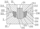
a sunken second assembly cavity 231 is formed in the middle of the top surface of the end rubber cylinder lower die 23, a fifth plane section 232 is formed on the top surface of the side wall of the second assembly cavity 231, a third conical hole section 234 is formed after the outer edge of the fifth plane section 232 is transited through a first arc transition section 233, the first arc transition section 233 is used for forming a transitional arc surface between the first plane 202 and the second conical surface 203 of the end rubber cylinder 2, the third conical hole section 234 is used for forming the second conical surface 203 of the end rubber cylinder 2, a sixth plane section 235 is formed by extending the third conical hole section 234 outwards, and a third conical surface section 236 is formed by extending the sixth plane section 235 outwards;
the end rubber sleeve mold core 24 comprises an end rubber sleeve mold core body part and a second external expansion part 241 positioned in the middle of the body part, the end rubber sleeve mold core body part is cylindrical, the bottom of the end rubber sleeve mold core body part is used for being matched with the second assembly cavity 231, the bottom surface of the second external expansion part 241 is used for being matched with a partial area of the fifth plane section 232, and the rest area of the fifth plane section 232 is used for forming the first plane 202 of the end rubber sleeve 2; the inner wall of the second outer expanding part 241 is used for forming the inner wall of the end rubber cylinder 2;
the end rubber sleeve middle die 22 comprises an end rubber sleeve middle die body 222 which is annular, a second annular table 221 is formed by protruding the inner wall of the middle part of the end rubber sleeve middle die body 222, the inner wall of the second annular table 221 is used for forming a second circumferential surface 204 of the end rubber sleeve 2, the bottom surface of the second annular table 221 is used for being matched with a sixth plane section 235, the inner wall area of the end rubber sleeve middle die body 222 on the lower side of the second annular table 221 is a third inclined surface section, the inner wall area of the end rubber sleeve middle die body 222 on the upper side of the second annular table 221 is a fourth inclined surface section, and the third inclined surface section is used for being matched with a third conical surface section 236;
end packing element goes up mould 21 middle part and has circular perforating hole, circular perforating hole is used for cooperating with end packing element mold core body portion upper portion, end packing element goes up the mould 21 bottom surface and has seventh plane section 211 along the circular perforating hole outside for with the cooperation of second portion 241 top surface that expands outward, seventh plane section 211 extends outward and is formed with fourth circular conical surface section 212, a first circular conical bore 201 for forming end packing element 2, fourth circular conical surface section 212 extends outward and is formed with eighth plane section 213, be used for cooperating with second ring platform 221 top surface, eighth plane section 213 extends outward and is formed with fifth circular conical surface section 214, be used for cooperating with fourth inclined surface section.
S202, opening the upper end rubber barrel mold 21, putting the baked and softened rubber into a mold cavity, covering the upper end rubber barrel mold 21, applying a downward pressure of 50-55T to the upper end of the upper end rubber barrel mold 21, and keeping for 3-5 min.
S203, opening the upper mold 21 of the end rubber cylinder, paving rubber in the mold cavity, covering the upper mold 21 of the end rubber cylinder, applying a downward pressure of 120-125T to the upper end, and keeping for 30-35 min.
S204, disassembling the mold, taking the end rubber tube 2 out, and placing the end rubber tube in an oven at a constant temperature of 60 ℃.
Specifically, will protect bowl 3 and end packing element 2 and make into end packing element assembly and include the step:
s301, placing the combined mold on a flat vulcanizing machine, heating to 100 ℃, and keeping for 2 hours.
As shown in fig. 8, the combined mold includes an upper combined mold, a middle combined mold 32, a lower combined mold 33, and a core 31.
The lower assembly die 33 comprises a third assembly cavity 331 with a recess in the middle of the top surface, the top surface of the sidewall of the third assembly cavity 331 is a ninth plane section 332, the ninth plane section 332 extends outwards to form a transition plane section 333, the transition plane section 333 extends outwards to form a tenth plane section 334, and the tenth plane section 334 extends outwards to form a sixth conical plane section 335;
the combined mold core 31 comprises a combined mold core body part and a third outward-expanding part 311 positioned in the middle of the body part, wherein the third outward-expanding part 311 is used for matching with the inner wall of the end rubber tube 2 and the inner wall of the part between the second plane 304 and the third plane 303 of the protection bowl 3;
the assembly middle mold 32 comprises an assembly middle mold body 322 which is annular, a third annular table 321 is formed on the inner wall of the middle part of the assembly middle mold body 322 in a protruding mode, the inner wall of the third annular table 321 is used for matching the second circumferential surface 204 of the rubber cylinder 2 with the third circumferential surface 305 of the protection bowl 3, the bottom surface of the third annular table 321 is used for matching with a tenth plane section 334, the inner wall area of the assembly middle mold body 322 on the lower side of the third annular table 321 is a fifth inclined plane section, the inner wall area of the assembly middle mold body 322 on the upper side of the third annular table 321 is a sixth inclined plane section, and the fifth inclined plane section is matched with a sixth conical plane section 335;
the upper die structure of the assembly is the same as the upper die 21 of the end rubber tube, the circular through hole of the upper die of the assembly can be matched with the upper part of the die core body of the assembly, the seventh plane section 211 of the upper die of the assembly is matched with the top surface of the third outward-expanding part 311, the fourth conical surface section 212 of the upper die of the assembly is matched with the first conical hole 201 of the end rubber tube 2, the eighth plane section 213 of the upper die of the assembly is matched with the top surface of the third circular platform 321, and the fifth conical surface section 214 of the upper die of the assembly is matched with the sixth inclined surface section.
S302, the protective bowl 3 is placed into the cavity of the lower die 33 of the combined body, and the end rubber tube 2 is sleeved on the body part of the combined body die core 31 of the combined body die core.
And S303, sequentially loading the assembly middle mold 32, the assembly mold core 31 sleeved with the end rubber tube 2 and the assembly upper mold on the assembly lower mold 33.
S304, applying a downward pressure of 120T-125T on the upper end face of the upper die of the assembly, and keeping for a preset time.
S305, raising the temperature of the vulcanizing machine to 150 ℃ and keeping the temperature for 720S.
And S306, raising the temperature of the vulcanizing machine to 190 ℃ and keeping the temperature for 57600S.
S307, disassembling the mold, taking out the end rubber tube assembly, cooling, and removing the die joint surface fly skin.
Specifically, assemble an end packing element assembly, well packing element 1, an end packing element assembly to the packer in proper order, including the step:
s401, sleeving one end rubber sleeve assembly on a middle shaft of the packer, and then pushing the end rubber sleeve assembly along the middle shaft by using an assembling tool 6 to abut against a fixed rubber sleeve seat 4.
Wherein, the assembling tool 6, as shown in fig. 10 to 12, comprises a ring plate 62 and an annular cylindrical wall 61 formed at one end of the ring plate 62, the outer edge of the ring plate 62 is overlapped with the outer wall lower edge of the annular cylindrical wall 61, the inner diameter of the through hole at the middle part of the ring plate 62 is matched with the outer diameter of the middle shaft, the inner diameter of the hollow channel of the annular cylindrical wall 61 is larger than the inner diameter of the through hole at the middle part of the ring plate 62, and the inner wall of annular cylindric wall 61 has predetermined interval with the inner wall of annular plate 62 in the radial direction, and the annular plate 62 is formed one side of annular cylindric wall 61 and is equipped with a plurality of springs 65 along the circumference, and spring 65 is connected with annular butt joint board 64, and annular cylindric wall 61 inner wall is equipped with a plurality of spouts 611 along the axial, and annular butt joint board 64 outer wall is formed with a plurality of sliding plates 641, and sliding plate 641 cooperates in spout 611, and the hole aperture of annular butt joint board 64 matches with the axis external diameter, and annular cylindric wall 61 outer wall is equipped with a pair of handle 63.
The assembling tool 6 is pushed along the middle shaft by using the assembling tool 6, the assembling tool 6 is sleeved on the middle shaft, the annular abutting plate 64, the annular plate 62 and the annular cylindrical wall 61 all penetrate through the middle shaft, one surface of the annular abutting plate 64 faces towards the end rubber cylinder assembly to be pushed, then the assembling tool 6 is moved by using the handle 63, the annular abutting plate 64 is contacted with the end rubber cylinder assembly, the annular cylindrical wall 61 is used for limiting the outer circumferential side, and the end rubber cylinder assembly is moved to abut against the fixed rubber cylinder seat 4.
S402, sleeving a middle rubber sleeve 1 on a middle shaft of the packer, and then pushing the middle rubber sleeve 1 along the middle shaft to abut against the assembled end rubber sleeve assembly by using the assembling tool 6. The operation mode is the same as the mode of pushing the end rubber cylinder assembly in the step S401.
And S403, sleeving one end rubber sleeve assembly on the central shaft of the packer, and pushing the end rubber sleeve assembly along the central shaft by using an assembling tool 6 to abut against the assembled middle rubber sleeve 1 to finish manufacturing. The operation mode is the same as the mode of pushing the end rubber cylinder assembly in the step S401.
Utilize the operation of erecting tool 6, can conveniently carry out the propelling movement, ensure in the removal, treat the end packing element assembly and well packing element 1 that remove and carry out evenly distributed in the power of circumference and carry out the propelling movement, can keep steadily qualitative, annular cylindric wall 61 carries on spacingly simultaneously, avoids in the removal extrusion outwards expanding.
The embodiment of the application aims to invent a rubber cylinder component which can effectively expand under the condition of lower compression force, so that the sealing purpose is achieved. The rubber cylinder component bears the pressure difference of 105MPa at 204 ℃, and only 13-15 tons of compressive force is required to be applied to the end face. At present, the rubber cylinder component with the same model on the market generally needs 22-25 tons of compression force to meet the requirement of bearing the pressure difference of 105MPa under the condition of 204 ℃. Under the working condition that the well depth is greater than 5000 meters, the compression cannot be effectively transmitted to the position of the rubber cylinder component, and the limited expansion and sealing of the rubber cylinder component can be met by applying larger compression force, so that the field use difficulty is increased, and the operation efficiency is reduced.
The foregoing is merely a preferred embodiment of this invention and is not intended to be exhaustive or to limit the invention to the precise form disclosed. It will be understood by those skilled in the art that various changes may be made and equivalents may be substituted without departing from the scope of the invention.