CN1137026A - Method and apparatus for forming wide mouth glassware - Google Patents
Method and apparatus for forming wide mouth glassware Download PDFInfo
- Publication number
- CN1137026A CN1137026A CN95115052A CN95115052A CN1137026A CN 1137026 A CN1137026 A CN 1137026A CN 95115052 A CN95115052 A CN 95115052A CN 95115052 A CN95115052 A CN 95115052A CN 1137026 A CN1137026 A CN 1137026A
- Authority
- CN
- China
- Prior art keywords
- neck ring
- support arm
- parison
- plunger carrier
- blank mould
- Prior art date
- Legal status (The legal status is an assumption and is not a legal conclusion. Google has not performed a legal analysis and makes no representation as to the accuracy of the status listed.)
- Pending
Links
Images


Classifications
-
- C—CHEMISTRY; METALLURGY
- C03—GLASS; MINERAL OR SLAG WOOL
- C03B—MANUFACTURE, SHAPING, OR SUPPLEMENTARY PROCESSES
- C03B11/00—Pressing molten glass or performed glass reheated to equivalent low viscosity without blowing
-
- C—CHEMISTRY; METALLURGY
- C03—GLASS; MINERAL OR SLAG WOOL
- C03B—MANUFACTURE, SHAPING, OR SUPPLEMENTARY PROCESSES
- C03B9/00—Blowing glass; Production of hollow glass articles
- C03B9/13—Blowing glass; Production of hollow glass articles in gob feeder machines
- C03B9/193—Blowing glass; Production of hollow glass articles in gob feeder machines in "press-and-blow" machines
- C03B9/1932—Details of such machines, e.g. plungers or plunger mechanisms for the press-and-blow machine, cooling of plungers
- C03B9/1936—Hydraulic or pneumatic displacement means of the plunger
-
- C—CHEMISTRY; METALLURGY
- C03—GLASS; MINERAL OR SLAG WOOL
- C03B—MANUFACTURE, SHAPING, OR SUPPLEMENTARY PROCESSES
- C03B9/00—Blowing glass; Production of hollow glass articles
- C03B9/13—Blowing glass; Production of hollow glass articles in gob feeder machines
- C03B9/193—Blowing glass; Production of hollow glass articles in gob feeder machines in "press-and-blow" machines
- C03B9/1932—Details of such machines, e.g. plungers or plunger mechanisms for the press-and-blow machine, cooling of plungers
Landscapes
- Engineering & Computer Science (AREA)
- Chemical & Material Sciences (AREA)
- Manufacturing & Machinery (AREA)
- Materials Engineering (AREA)
- Organic Chemistry (AREA)
- Mechanical Engineering (AREA)
- Containers Having Bodies Formed In One Piece (AREA)
- Blow-Moulding Or Thermoforming Of Plastics Or The Like (AREA)
- Moulds For Moulding Plastics Or The Like (AREA)
- Re-Forming, After-Treatment, Cutting And Transporting Of Glass Products (AREA)
Abstract
A method and a device for manufacturing a wide mouth glass service include the arrangement of a primary mold, a blow mold, a neck ring and a supporter. The supporter is internally provided with a movable formed punch. The primary mold is moved to a location for receiving glass gob. The neck ring is positioned on the primary mold. The glass gob is supplied in the primary mold. The positioning supporter is jointed with the neck ring. The formed punch extends into the primary mold to force the glass to be deformed to be led into the neck ring to become a parison. The formed punch is retracted and the parison is removed from the neck ring. The primary mold is lowered and kept to be erect and moves into the blow mold together with the neck ring. The blow mode is closed and the neck ring is opened so as to release the parison in the blow mold. The neck ring is withdrawn to the initial position and the blow parison becomes a hollow product. The blow mold is opened to take out the product.
Description
The present invention relates to the method and apparatus of forming wide mouth glassware.
At the equipment of the formed glass vessel of known type-known as I.S, in the type equipment, be on the position of standing upside down, to form parison earlier by compacting, then, it is turned and is sent to a blow mold, so that be blow molded into the finished product such as container.This class machine is published in, for example, and U.S. Patent No. 1,911,119; 2,289,046; With 3,024, in 571.In U.S. Patent No. 4,004, in 906, disclose a kind of in order under erectility, to form a parison and this parison to be sent to the equipment of blow mold by means of a device, said transport unit has used one to hang over two loop chains on the sprocket wheel, one of them sprocket wheel is arranged on the free-ended place near the neck ring support arm, and another sprocket wheel then is arranged on the installation pivot location place of neck ring support arm, so that isolate support arm.
The purpose of this invention is to provide a kind of new method and apparatus that is intended to forming wide mouth glassware; This method and apparatus is produced wide mouth glassware, and can enough less pressure moulding parison more promptly, and then make the better quality of glassware; Can handle one or more glass gobs; This glass gob preferably passes neck ring and sends a vertical firm blank mould to; This processing method guarantees that drift can be quicker and centering more accurately, and, glass mobile less in blank mould; This processing method neither needs funnel mechanism also not need blocking mechanism; And this equipment can move reliably with higher speed, and required minimal maintenance.
According to the present invention, comprise in order to the method and apparatus of making wide mouth glassware: a firm blank mould is set; A separable type blow mold is set; A separable type neck ring is set; A plunger carrier is set, and this support has a drift that can move within it; Blank mould is moved upwards up to the position of being convenient to admit glass gob; Neck ring is placed on the blank mould; The said blank mould of a glass gob delivery; Plunger carrier is positioned to engage with said neck ring; Make drift put in above-mentioned blank mould,, thereby form a parison so that make glass deformation and force glass to enter neck ring; After this, remove from neck ring the drift withdrawal and plunger carrier; Blank mould is reduced; When keeping parison to be in the vertical stand-up state, the parison of neck ring and Qi Nei moved to together the position between the two halves blow mold of opening; Center on parison and closed blow mold; Opening neck ring is discharged into parison in the blow mold; Neck ring is returned to that starting position of its close blank mould; Parison is blow molded into a hollow glasswork; Open blow mold and take out the good glasswork of blowing.Glass gob is preferably carried by neck ring.In addition, the drift that extends with respect to above-mentioned support is preferably along with this plunger carrier moves and beginning pressed glass to contacting with above-mentioned neck ring.
The present invention's method and apparatus preferably includes a neck ring support arm is set, and makes this support arm rotate around one first transverse axis, and a neck ring clamper is set, and in order to the clamping neck ring, said neck ring clamper is rotatably supported on the neck ring support arm.This method and apparatus further comprises: be provided with one and transmit support arm, this end that transmits support arm rotates around one second fixing horizontal axle, this second transverse axis and first transverse axis separate each other, the other end that transmits support arm installs on the neck ring clamper rotationally, and, this transmission support arm links to each other with above-mentioned first transverse axis so rotationally---and be that the neck ring support arm can cause transmitting support arm round rotatablely moving of first transverse axis and rotates round second transverse axis, and, when the position that neck ring is moved between the blow mold of opening, keep above-mentioned parison to be in vertical axial state.
Fig. 1-the 5th represents the synoptic diagram of the consecutive steps in the method for the present invention.
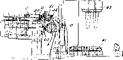
Fig. 6 is the front view of an expression particular embodiment equipment of the present invention.
Fig. 7 is the orthographic plan of the part of equipment shown in Figure 6.
Fig. 8 is that right-hand member is seen end view in the past from Fig. 7.
Fig. 9 is the sectional view of being got along 9-9 line among Fig. 7.
Figure 10 is the orthographic plan of the part of the equipment shown in Fig. 7-9, and wherein, the neck ring clamper is in the appropriate location.
Figure 11 is the side-view of equipment shown in Figure 10.
Figure 12 is the orthographic plan of another part of equipment shown in Figure 6.
Figure 13 is the partial plan layout of the refrigerating unit of neck ring.
Figure 14 sees end view in the past from the right side of Figure 13.
Figure 15 is the vertical cross section of plunger mechanism.
The synoptic diagram of the consecutive steps when Figure 16 is expression moulding one parison.
Figure 17-the 20th, the synoptic diagram of the part of equipment shown in Figure 6 when a series of coherent location of equipment.
Figure 21 is the synoptic diagram of the displacement of expression parison between pressing position and blowing position.
Below in conjunction with accompanying drawing preferred embodiment is described.
Particular embodiment method and apparatus of the present invention relates to known I.S. technology, and wherein, glass gob is in a blank station moulding, and is sent to a blow moulding station, so that be blow molded into glass utensil products such as Glass Containers.Referring to Fig. 1-5, according to the present invention, this method has been used a firm blank mould 30 that is arranged on the blank station.This vertical firm blank mould 30 can be moved upwards up to feed location.Separable type neck ring 31 synchronously moves to the feed location above blank mould 30, and a fused glass gob also passes neck ring 31 simultaneously and transmits blank mould 30 (Fig. 2).Plunger carrier 32 has supported a drift hydro-cylinder 33, and this cylinder 33 comprises a drift 34 that is installed on the piston 35.After glass gob passed neck ring 31, plunger carrier 32 was moved down into drift hydro-cylinder 33 in the position at the top of neck ring 31 (Fig. 3) immediately.Drift hydro-cylinder 33 just descending enter its position in, the drift 34 that stretches out begins to compress into glass (Fig. 3).One telescopic in and gripping sleeve 36 be positioned at fully at drift hydro-cylinder 33 before the top of neck ring 31, provide accurate centering for drift 34 passes neck ring 31 and enters glass gob, and, also guarantee compacting during neck ring 31 do not pressed off.When plunger carrier 32 is positioned it in neck ring 31 vertical final positions to drift hydro-cylinder 33, these drift hydro-cylinder of independently controlling 33 mobile pistons 35, so that drift 34 is deeper compressed into glass gob, thereby finish its stroke and force glass upwards to enter neck ring 31 (Fig. 4).Routine compacting and technological process for blowing method part that this processing method is different from the I.S. machine are, compare with the I.S. method of routine, in the method for the invention, glass only is moved upwards up to neck ring 31 from the bottom of blank mould 30, and in the I.S. of routine method, glass is moved upwards up to one from the bottom of the blank mould that stands upside down and stops end, turns back to neck ring then downwards.In the method for the invention, the less mobile permission of glass is with less pressure moulding parison more quickly, and can make present method produce the container of better quality.
After the compacting, drift hydro-cylinder 33 is drift 34 withdrawal, and, the plunger carrier 32 drift hydro-cylinder 33 that moves up, and shift to next door (Fig. 5).Then, when firm blank mould 30 moves down, parison is moved into place in the blow mold 39 (Fig. 5) of blowing on the station from the top.Therefore, this parison transmits under the vertical stand-up state, does not resemble the ordinary method to transmit with the state that stands upside down.Can make that so the mobile radian of parison is less, thereby reduce those centrifugal force of causing parison outwards to wave.Therefore, before the work of blowing can begin eventually, parison was positioned over time less required on the base plate of blow mold (Fig. 5).After neck ring 31 was opened and parison is discharged into blow mold 39, the blowing work of the parison in blow mold 39 began (Fig. 5), and the good container of blowing is subsequently undertaken by the mode of the routine of I.S. machine to the transmission of an e Foerderanlage from blow mold 39.
Glass gob is directly put into firm vertical blank mould 30 by neck ring 31 and has been saved the required funnel mechanism of glass-guiding.Save run duration like this, the time of saving can increase to the blank time or be used for acceleration cycle.After glass gob is added firm blank mould 30 by neck ring 31, plunger carrier drops to immediately on the position at the top of neck ring 31, the drift hydro-cylinders of one or more independent controls can be installed on this plunger carrier, and this will decide according to the quantity of the glasswork of while moulding.The compacting of the glass in the firm blank mould 30 is reduced to its final aligned position to drift hydro-cylinder 33 along with plunger carrier 32 and begins.Therefore, drift hydro-cylinder 33 have one stretch out can compress in and gripping sleeve 36 so that can be as early as possible and accurately compacting, and can not press off neck ring.When drift hydro-cylinder 33 is in its final position, it will force drift 34 further downwards, enter firm blank mould, so that the last compacting of parison.
Fig. 6 show particular embodiment of the present invention, in order to the equipment of forming wide mouth glassware, this equipment is resembling this paper those U.S. Patent No.s 3,024,571 and 3,233 incorporated by reference, the such I.S. glass shaper described in 999 is the basis.Equipment shown in Figure 6 is a pair of gob machine, but just as known in the art, it can be that a thin material drips machine or comprises three gobs and many gobs machine of four gobs.This equipment comprises a branch electronic box 40, divides electronic box 40 that blank mould 41 is bearing in the blank forming station, and blow mold 42 is bearing in the blowing station.Improve like that just as described herein those, this equipment comprise one on the blank forming station the drift hydro-cylinder and the transmission subassembly 44 that links of 43, one of rack assemblies and neck ring clamper and one usually the transmission of upset parison prop up arm assembly 45 (changing as described herein).This equipment comprises that one is equipped with the blank mould hydro-cylinder subassembly 46 of firm blank mould 41 on it, arrives the receiving position that receives from the glass gob of a feeder (not shown) so that move up.
As shown in figure 10, a neck ring clamper and a transmission arm assembly 45 comprise some hole 47a, in order to a pair of neck ring 46 (Figure 15 and 16) is bearing in the neck ring clamper 47 that is positioned on the neck ring support arm 48.Support arm 48 is attached to T type geosynclinal convex separately by their T type trough connection and rises on 49.Each projection 49 is in aggregates with sleeve 50 separately.Shown in Fig. 7-9, sleeve 50 separately in week with spline fitted, and be assembled to by the complementary spline on the middle portion of overstriking of a trip shaft 51.As described in resembling, each sleeve 50 is suitable for coaxial 51 rotations and endwisely slip together along axle 51.Two ends of axle 51 are installed in rotation in the bearing, and bearing is fixed on the upright shafts bolster of supporting foundry goods at the neck end, and this supporting foundry goods is attached on the basic frame of machine.
Axle 51 is rotating so that eck mould is sent to the blow moulding station from the parison station, a back station be support arm 48 from the parison station rotate about 180 ° reach.Blow mold (not shown) amalgamation, separable is installed on a pair of support arm in known manner, and this a pair of support arm rotates around a vertical central pin shaft with the pattern of scissors.This bearing pin is installed on the frame rigidly by the supporting foundry goods.Also have two to be installed to vertical side bearing pin or axle on the frame rigidly by foundry goods, that those link to each other, drive the link gear (not shown) in order to the blow mold of open and close blow mold support arm and be rotatably installed in known manner on these bearing pins.These vertical axes shown in this article are represented the blow mold position or the station of machine.For simplicity, all the other component of all the other component of blow mold mechanism and first mold mechanism have deliberately saved from accompanying drawing when illustrating for the present invention.
The rotation of axle 51 is realized that by gear 53 gear 53 is fixed to the middle part of axle 51 rigidly by a key and is meshed with a vertically arranged tooth bar 54a.Tooth bar 54a is positioned at a hydraulic operated oil cylinder---the upper end (Fig. 6) of the piston rod 54 of piston motor 55.The to-and-fro movement of tooth bar 54a causes rotatablely moving of gear 53, and conversely, gear 53 makes axle 51 rotate again.Neck ring support arm 48 moves on a upset track that rotates owing to the splined between axle 51 and two bracket sleeve tubes 50 on it.
Neck ring support arm 48 since sleeve 50 along the spline on the axle 51 slide and mutually near and leave mutually so that open and close neck ring clamper 47.The amount of movement of opening is subjected to the control of block 52.This motion realizes that by opposed, single-acting formula, hydraulic operated oil cylinder-piston assembly 55 55 pairs of springs of subassembly work.Should be to resemble for example this paper United States Patent (USP) 3,233 incorporated by reference in order to the device that rotates, original and known in the such I.S. machine described in 999.According to the present invention, one cranks arm 60 is installed on the axle 51, so that therewith rotate.
Be substantially similar to this paper United States Patent (USP) incorporated by reference 3 in order to the device (Figure 12) of plunger carrier being shifted to the working position and removing from the working position, 024, device in 571, only the device of this paper be handle from the top of blank mould rather than handle from the below.
According to the present invention, separable or separable type neck ring 46 is bearing on the firm neck ring clamper 47, is installed in rotation on the support arm 48 to two ends in the middle of the neck ring clamper 47.Neck ring support arm 48 respectively has the pivot 61 that is positioned on the arm 48.These pivots extend internally (Figure 10) in the dimple on the neck ring clamper 47 into.
Referring to Figure 15, plunger carrier 70 has carried two cover drift subassemblies 71, and every suit subassembly comprises a hydro-cylinder 72, and this hydro-cylinder 72 has a piston 73 that has a piston rod 74, and a drift 75 has been installed on piston rod 74.One sleeve 76 is installed in the lower end of support 70, and is pushed away downwards by a spring 77 compressible ground.A circular trapezoidal groove 78 has been made in the lower end of sleeve 76, and this groove is suitable for being meshed with a circular convex edge 46a of complementary on neck ring 46, so that drift and neck ring centering accurately.In the bottom of neck ring 46 a cyclic convex edge 46b is arranged also, in order to blank mould on complementary groove 41a engagement so that aligning between neck ring and the blank mould.
Referring to Fig. 6,10,11 and 17-21, according to the present invention, said transport unit comprises that one transmits support arm 80, one end of support arm 80 rotates round the second fixing horizontal axis B that the axis A with axle 51 is separated with a segment distance, and its other end is installed on the neck ring support arm 48 in the mode that can rotate at axis C place.One end of one connecting rod 81 60 links to each other at axis D place with cranking arm rotationally, and its other end be pivotally connected at the axis E place between the two ends of transmitting support arm 80 certain a bit.Transmit a part 80a and a long part 80b that support arm 80 comprises the weak point that a blunt angle is arranged each other, and pivot center E just is in this two-part junction.As a result, shown in the synoptic diagram of Figure 21, the mobile radius R of the pivot D on 60 that cranks arm
1With the mobile radius R of pivot E around axis B
2Be identical; And the radius R that pivot F moves around axis A
3Center on the radius R that axis B moves with pivot C
4Be identical.On any position, crank arm 60 and transmit part 80a keeping parallelism relation all of the weak point of support arm 80, and also keeping parallelism relation of long part 80b and neck ring support arm 48.
Referring to Figure 12-14, taked to utilize the side's of arranging bag by the air cooling neck ring 46 of opposed arc pumping chamber 90 feeds.Each pumping chamber 90 comprises several cells 91,92,93 and 94.The supply air---promptly: can regulate from the size that air source enters the inlet of each cell by change like this by the air capacity that enters each cell by adjustable plate 95 for cell 91~94.Each piece plate 95 passes the groove 98 on this plate 95 by one and puts in a threaded hole 99 interior bolts 97 and remains on setting.
During work, two gobs pass neck ring and enter blank mould, and according to the described method maneuvering device of 1-5 in conjunction with the accompanying drawings.
Referring to Figure 17-20, show the situation of equipment in each working position: gob to the transmission of blank mould and plunger carrier 70 with respect to blank mould move (Figure 17) to the blank mould top; The compacting of glass (Figure 18); Parison is to move (Figure 19) of blow mold station; And parison is in the location of blow mold station, so that blowing (Figure 20).
Figure 21 is a synoptic diagram, and showing around the transport unit of two horizontal axis movements is how parison to be remained on erect position.
Do not need to come glass-guiding by neck ring and enter blank mould, saved moulding round-robin additional period like this with a funnel mechanism.In other forming method on the I.S. machine, glass gob is placed on the bottom of blank mould or the top of a drift, meanwhile, other mechanism is just shifting to next door or just mobile in place, so that begin compacting.Can cause the undue and uneven cooling of glass the cycling time that this motion spent, when glass was blow molded into last shape in blow mold, the undue and inhomogeneous cooling of glass can produce bad jar (unit of capacitance) and distribute.
With as United States Patent (USP) 4,004, parison is different to be in pointed transmitting with sprocket wheel, chain and gear in 906, present method makes neck ring clamper maintenance level and more stable with an inflexible link gear, thereby produces few manufacturing deficiency.
Therefore, as can be seen, provide a kind of method and apparatus that is intended to the novelty of forming wide mouth glassware; This method and apparatus is produced wide mouth glassware, and allows with less pressure moulding parison more quickly, so that the better quality of glassware; Can handle one or more glass gobs; This glass gob is preferably sent a vertical firm blank mould to by neck ring; This method guarantees that drift can be quickly and centering more accurately, simultaneously, and glass mobile less in blank mould; This method neither needs funnel mechanism also not need blocking mechanism; And this equipment can move in a reliable mode with higher speed, and, required minimal maintenance.
Claims (49)
1. method of making wide mouth glassware comprises:
A firm blank mould is set,
A separable type blow mold is set,
A separable type neck ring is set,
A plunger carrier that has a removable drift on it is set,
Neck ring is placed on the said blank mould,
Directly send the fused glass gob to said blank mould,
Plunger carrier is positioned to be meshed with said neck ring,
Make drift extend, put in said blank mould,, thereby form a parison so that make glass deformation and force glass to enter neck ring with respect to plunger carrier,
After this, make plunger carrier withdraw, and plunger carrier removed from neck ring with respect to blank mould,
When keeping parison to be in vertical erectility, neck ring is moved to position between the two halves blow mold of opening together with the parison on it,
Around the closed blow mold of parison,
Open neck ring, parison be discharged into blow mold,
Neck ring is returned to its that original position near blank mould,
Parison is blow molded into a hollow glasswork,
Open blow mold,
The glasswork that blowing is good takes out.
2. method according to claim 1 is characterized in that, the step of glass gob being sent to blank mould realizes by passing neck ring glass-guiding gob.
3. method according to claim 2 is characterized in that, when plunger carrier was entering its position on above-mentioned neck ring, drift began to extend with respect to plunger carrier, begins to press glass when engaging thereby drift is moved to neck ring at plunger carrier.
4. method according to claim 3 is characterized in that, the above-mentioned plunger carrier localization step that makes comprises plunger carrier with neck ring centering.
5. method according to claim 4 is characterized in that, said to make the step of plunger carrier centering be to realize in the process that moves to the position that engages with neck ring.
6. method according to claim 5 is characterized in that, comprises and flexibly supports plunger carrier, so that this support engages with neck ring compressiblely.
7. according to each described method among the claim 1-6, it is characterized in that, comprise a neck ring clamper in order to the clamping neck ring is set, this neck ring clamper is rotatably supported on the neck ring support arm, and the neck ring support arm can rotate round one first fixing horizontal axle.
8. method according to claim 7 is characterized in that, comprises the step that above-mentioned blank mould is moved upwards up to the position of being convenient to receive glass gob.
9. method according to claim 8, it is characterized in that, the above-mentioned step that when keeping parison to be in vertical erectility neck ring is moved to the position between the two halves blow mold of opening together with the parison on it comprises: be provided with one and transmit support arm, one end of this transmission support arm is round being separated with the second fixing horizontal axle rotation of a segment distance with the first fixing horizontal axle, the other end of this transmission support arm is pivotally mounted on the neck ring clamper, and, this transmission support arm and first transverse axis interrelate rotationally, making the neck ring support arm can cause transmitting support arm around rotatablely moving of first transverse axis moves around second transverse axis, and, when the position of neck ring being shifted between the blow mold of opening, keep parison to be in erectility.
10. method according to claim 9 is characterized in that, comprise a step of cranking arm of rotating around first transverse axis is set, and the step that said contact transmits support arm comprises described transmission support arm is linked to each other with cranking arm.
11. method according to claim 10 is characterized in that, is included on the said neck ring clamper several neck rings are set, and several blank moulds are set, several drifts and several blow molds.
12. an equipment of making wide mouth glassware comprises:
One firm blank mould,
One separable type blow mold,
One separable type neck ring,
One has the plunger carrier of drift movably on it,
In order to neck ring being placed into the device on the blank mould,
In order to glass gob being delivered into the device of blank mould,
In order to plunger carrier being put into the device of the position that engages with neck ring,
This plunger carrier comprises with the glass deformation and force glass to enter that thereby neck ring forms a parison and drift withdrawal and device that plunger carrier is removed from neck ring so that drift further puts in blank mould,
In order to when keeping parison to be in vertical axial position, neck ring is moved to the position between the two halves blow mold of opening and just when blowing neck ring is being returned to its device near that original position of blank mould at parison together with the parison on it
In order to opening neck ring parison being discharged into the device of blank mould,
In order to around the closed blow mold of parison and parison is blow molded into the device of hollow glasswork.
13. equipment according to claim 12 is characterized in that drift stretches out from plunger carrier, thus make this drift at plunger carrier to moving when contacting and begin pressed glass with neck ring.
14. equipment according to claim 13 is characterized in that, plunger carrier comprises to be used so that the device of plunger carrier and neck ring centering.
15. equipment according to claim 14 is characterized in that, plunger carrier comprises the device that engages neck ring compressiblely.
16. according to each described equipment among the claim 12-15, it is characterized in that, comprise a neck ring support arm, make the device that this neck ring support arm rotates around the first fixing horizontal axle, the one neck ring clamper in order to the said neck ring of clamping is rotatably supported in device on the neck ring support arm to this neck ring clamper.
17. equipment according to claim 16 is characterized in that, comprises in order to above-mentioned blank mould is upwards moved into the device of the position of being convenient to receive glass gob.
18. equipment according to claim 17, it is characterized in that, saidly comprise that in order to the device that when keeping parison to be in vertical erect position, neck ring is moved to the position between the two halves blow mold of opening together with the parison on it one transmits support arm, make an end of this transmission support arm round being separated with the device that the second fixing horizontal axle of certain distance rotates with first transverse axis, the other end of this transmission support arm is installed to device on the neck ring clamper rotationally, make the device that this transmission support arm and first transverse axis interrelate rotationally, rotate around second transverse axis thereby make the neck ring support arm can cause transmitting support arm, and when the position of neck ring being shifted between the blow mold of opening, keep parison to be in vertical erect position around rotatablely moving of first transverse axis.
19. equipment according to claim 18 is characterized in that, comprises one by cranking arm of rotating of the above-mentioned device that makes the neck ring support arm rotate around first transverse axis and device that described transmission support arm and this rotation of cranking arm are linked.
20. equipment according to claim 19 is characterized in that, comprises several neck rings on the neck ring clamper, several blank moulds, several drifts and several blow molds.
21. equipment according to claim 20 is characterized in that, comprises a pair of pumping chamber, each pumping chamber has half the arc opening in the contiguous neck ring, and each pumping chamber has several cells and regulates the device of the air flow quantity that flows to each cell.
22. equipment according to claim 21 is characterized in that, the device of said adjusting flow comprises the plate that links to each other with the inlet mouth of each cell and in order to adjust the device of this plate with respect to the position of separately cell.
23. equipment according to claim 22 is characterized in that, said device comprises that is passed a bolt and the nut of lemon on this bolt that is positioned at the groove on the said plate.
24. one kind which is provided with each station, in order to make the equipment of glassware, comprise: a blank mould station, one is separated with the separable type blow mold station of a segment distance with said blank mould station, a separable type neck ring, in order to neck ring is positioned the device on the blank mould, in order to glass gob is infeeded the device of blank mould, so, can make a parison to glass gob at the blank mould station, this parison is sent to the blow mold station and at this blow mold station parison is blow molded into hollow goods, and its improvement comprises:
At the device of blank mould station with axial position supporting blank mould,
In order to when keeping parison to be in vertical axial position neck ring is moved to the position between the two halves blow mold of opening and just when blowing neck ring returned to the device in that original position of its close blank mould at parison together with the parison on it, this device comprises:
One neck ring support arm,
Make the device that this neck ring support arm rotates around the first fixing horizontal axle,
One neck ring clamper in order to the clamping neck ring,
In order to the neck ring clamper being bearing in rotationally the device on the neck ring support arm,
One transmits support arm,
Make an end of this transmission support arm around being separated with the device that the second fixing horizontal axle of a segment distance rotates with first transverse axis,
In order to the other end that transmits support arm being installed to rotationally the device on the neck ring clamper,
Make the transmission support arm and first transverse axis rotate the device that links, rotate around second transverse axis thereby make the neck ring support arm can cause transmitting support arm, and when the position of neck ring being shifted between the blow mold of opening, keep above-mentioned parison to be in erect position around rotatablely moving of first transverse axis.
25. equipment according to claim 24 is characterized in that, comprises one by the above-mentioned device of cranking arm and making the transmission support arm and cranking arm and be rotatedly connected that device drove that makes that the neck ring support arm rotates around first transverse axis.
26. equipment according to claim 25 is characterized in that, comprises one and the corresponding plunger carrier of blank mould,
Plunger carrier location is made it the device that engages with neck ring,
This plunger carrier comprises with the glass deformation and force glass to enter that thereby neck ring forms a parison and drift withdrawal and device that plunger carrier is removed from neck ring so that drift further puts in said blank mould.
27. equipment according to claim 26 is characterized in that drift stretches out from plunger carrier, begins pressed glass when engaging thereby this drift is moved to neck ring at plunger carrier.
28. equipment according to claim 27 is characterized in that, plunger carrier comprises to be used so that the device of plunger carrier and neck ring centering.
29. equipment according to claim 28 is characterized in that, plunger carrier comprises the device that engages said neck ring compressiblely.
30. equipment according to claim 29 is characterized in that, comprises a pair of pumping chamber, each pumping chamber has one near half the arc opening in the neck ring, and each pumping chamber has several cells and regulates the device of the air flow quantity that flows to each cell.
31. equipment according to claim 30 is characterized in that, the device of said adjusting flow comprises the plate that links to each other with the inlet mouth of each cell and in order to adjust the device of this plate with respect to the position of separately cell.
32. equipment according to claim 31 is characterized in that, said device comprises that one is passed bolt that is positioned at a groove on the flat board and the nut that is screwed on this bolt.
33., it is characterized in that, comprise several neck rings that are positioned on the neck ring clamper, several blank moulds and several blow molds according to each described equipment among the claim 24-32.
34. one kind which is provided with each station, in order to make the equipment of glassware, comprise: a blank mould station, one is separated with the separable type blow mold station of a segment distance with the blank mould station, a separable type neck ring, in order to neck ring is positioned the device on the blank mould, in order to glass gob is infeeded the device of blank mould, on the blank mould station, can make a parison to glass gob, this parison is sent to the blow mold station and at this blow mold station parison is blow molded into hollow goods, and its improvement comprises:
At the device of blank mould station with axial position supporting blank mould,
In order to when keeping parison to be in hard straight axial position, neck ring is moved to position between the two halves blow mold of opening together with the parison on it, and just when blowing neck ring is being returned to its device near that original position of blank mould at parison, this device comprises:
One neck ring support arm,
Make the device that this neck ring support arm rotates around the first fixing horizontal axle,
One neck ring clamper in order to the clamping neck ring,
One in order to being bearing in the neck ring clamper rotationally the device on the neck ring support arm,
A pair of pumping chamber, each pumping chamber have one near half the arc opening in the neck ring, and each pumping chamber has several cells and regulates the device of the air flow quantity that flows to each cell.
35. equipment according to claim 34 is characterized in that, the device of said adjusting flow comprises the plate that links to each other with the inlet mouth of each cell and in order to adjust the device of this plate with respect to the position of separately cell.
36. equipment according to claim 35 is characterized in that, said device comprises the bolt and the nut of lemon on this bolt that pass a groove on the flat board.
37. for glass gob wherein the moulding of blank mould station and be sent to the blow mold station equipment usefulness one telescopic neutralization is clamped plunger carrier, comprise
A drift,
A neck ring,
This plunger carrier comprises the device that with respect to this support drift is stretched out in order to when just being placed on the neck ring at plunger carrier, begins pressed glass when engaging thereby make this drift move to said neck ring at plunger carrier.
38., it is characterized in that plunger carrier comprises to be used so that the device of plunger carrier and neck ring centering according to the described equipment of claim 37.
39., it is characterized in that plunger carrier comprises the device that engages neck ring according to the described equipment of claim 38 compressiblely.
40. according to each described equipment among the claim 37-39, it is characterized in that comprising a neck ring support arm, the device that the neck ring support arm is rotated around the first fixing horizontal axle, the neck ring clamper in order to the clamping neck ring is rotatably supported in device on the neck ring support arm to the neck ring clamper.
41. according to the described equipment of claim 40, it is characterized in that, comprise in order to when keeping parison to be in vertical erect position, neck ring is moved to the device of the position between the two halves blow mold of opening together with the parison on it, this device comprises that one transmits support arm, an end that make to transmit support arm is around being separated with the device that the second fixing horizontal axle of a segment distance rotates with first transverse axis, the other end that transmits support arm is contained in device on the neck ring clamper rotationally, rotate the device that links transmitting the support arm and first transverse axis, thereby making the neck ring support arm cause transmitting support arm around rotatablely moving of first transverse axis rotates around second transverse axis, and, between the blow mold of opening, keeping neck ring when mobile parison to be in vertical erect position.
42. according to the described equipment of claim 41, it is characterized in that, comprise one by the above-mentioned device of cranking arm and making the transmission support arm and cranking arm and be rotatedly connected that device drove that the neck ring support arm rotates around first transverse axis that makes.
43., it is characterized in that, comprise that several are clipped in the neck ring on the neck ring clamper, several blank moulds, several drifts and several blow molds according to the described equipment of claim 42.
44., it is characterized in that according to the described equipment of claim 43, comprise a pair of pumping chamber, each pumping chamber has one near half the arc opening in the neck ring, and first pumping chamber comprises several cells and regulates the device of the air flow quantity that flows to each cell.
45., it is characterized in that the device of said adjusting flow comprises the plate that links to each other with the inlet mouth of each cell and in order to adjust the device of this plate with respect to the position of separately cell according to the described equipment of claim 44.
46., it is characterized in that said device comprises the bolt and the nut of lemon on this bolt that pass a groove on the plate according to the described equipment of claim 45.
47. for glass gob wherein in a blank mould station moulding and be sent to the usefulness of the equipment of a blow mold station by the neck ring support arm,
A pair of pumping chamber, each pumping chamber have half a arc opening near neck ring, and each pumping chamber has several cells and regulates the device of the air flow quantity that flows to each cell.
48., it is characterized in that the device of said adjusting flow comprises the plate that links to each other with the inlet mouth of each cell and in order to adjust the device of this plate with respect to the position of separately cell according to the described equipment of claim 47.
49., it is characterized in that said device comprises the bolt and the nut that is screwed on this bolt that pass a groove on the plate according to the described equipment of claim 48.
Applications Claiming Priority (2)
| Application Number | Priority Date | Filing Date | Title |
|---|---|---|---|
| US08/281,718 US5588981A (en) | 1994-07-28 | 1994-07-28 | Apparatus for forming wide mouth glassware |
| US281,718 | 1994-07-28 |
Publications (1)
| Publication Number | Publication Date |
|---|---|
| CN1137026A true CN1137026A (en) | 1996-12-04 |
Family
ID=23078496
Family Applications (1)
| Application Number | Title | Priority Date | Filing Date |
|---|---|---|---|
| CN95115052A Pending CN1137026A (en) | 1994-07-28 | 1995-07-27 | Method and apparatus for forming wide mouth glassware |
Country Status (17)
| Country | Link |
|---|---|
| US (2) | US5588981A (en) |
| EP (1) | EP0694505A3 (en) |
| JP (1) | JPH0891850A (en) |
| KR (1) | KR960004241A (en) |
| CN (1) | CN1137026A (en) |
| AU (1) | AU2719095A (en) |
| BR (1) | BR9503492A (en) |
| CA (1) | CA2154946A1 (en) |
| CO (1) | CO4440584A1 (en) |
| CZ (1) | CZ191295A3 (en) |
| EE (1) | EE9500041A (en) |
| FI (1) | FI953524A (en) |
| LT (1) | LT95090A (en) |
| LV (1) | LV11313B (en) |
| PE (1) | PE27475295A1 (en) |
| PL (1) | PL309762A1 (en) |
| ZA (1) | ZA956267B (en) |
Cited By (2)
| Publication number | Priority date | Publication date | Assignee | Title |
|---|---|---|---|---|
| CN102408185A (en) * | 2011-07-26 | 2012-04-11 | 凤阳县龙兴玻璃有限公司 | One-step forming die for cold water kettle with handle |
| CN112851084A (en) * | 2021-03-25 | 2021-05-28 | 重庆健力玻璃制品有限公司 | Machine-made jazz mouth glassware and preparation method thereof |
Families Citing this family (11)
| Publication number | Priority date | Publication date | Assignee | Title |
|---|---|---|---|---|
| US5766292A (en) * | 1996-09-23 | 1998-06-16 | Owens-Brockway Glass Container Inc. | Method and apparatus for making wide mouth hollow glass articles |
| FR2770510B1 (en) * | 1997-11-06 | 2000-03-31 | Emhart Glass Sa | MOLD OPENING AND CLOSING MECHANISM FOR AN INDIVIDUAL SECTOR FORMING MACHINE |
| DE10144112A1 (en) * | 2001-09-08 | 2003-03-27 | Hermann Heye I I | Blow molding a gob in a blow mold of a blow molding station of a glass molding machine comprises axially moving a block structure into a working position before the mold halves of a blow mold are closed |
| US7073352B2 (en) * | 2002-03-07 | 2006-07-11 | Vitro Global, S.A. | Method and a machine for the production of hollow glassware articles |
| US7185515B2 (en) * | 2003-06-27 | 2007-03-06 | Owens-Brockway Glass Container Inc. | Invert arm assembly for glassware forming machine |
| TWI245747B (en) * | 2004-07-30 | 2005-12-21 | Asia Optical Co Inc | Glass molding forming device capable of positioning glass material, supporting lens |
| CN102211852B (en) * | 2011-04-19 | 2013-01-02 | 山东三金玻璃机械股份有限公司 | Servo drive parallel switch |
| CN104193149B (en) * | 2014-08-26 | 2017-01-25 | 德清才府玻璃股份有限公司 | Opening die |
| USD754911S1 (en) | 2015-03-05 | 2016-04-26 | Bocci Design and Manufacturing Inc | Glass pendant for decorative light fixtures |
| US20180237324A1 (en) * | 2017-02-13 | 2018-08-23 | Keith Covert | Modular alignment process system for mold components |
| CN113121088B (en) * | 2021-04-20 | 2022-07-15 | 重庆星源玻璃器皿有限责任公司 | Glass product blowing apparatus |
Family Cites Families (35)
| Publication number | Priority date | Publication date | Assignee | Title |
|---|---|---|---|---|
| US1259281A (en) * | 1915-07-03 | 1918-03-12 | Hartford Fairmont Co | Manufacture of glassware. |
| US1618747A (en) * | 1926-03-04 | 1927-02-22 | Edward E Bartlett | Making blown-glass articles |
| US1781565A (en) * | 1928-03-13 | 1930-11-11 | Fed Glass Company | Method and apparatus for making articles of glassware |
| US1911119A (en) * | 1928-05-04 | 1933-05-23 | Hartford Empire Co | Glassware forming machine |
| US1876005A (en) * | 1930-01-09 | 1932-09-06 | Owensillinois Glass Company | Glassware forming machine |
| US1888318A (en) * | 1930-05-08 | 1932-11-22 | Owens Illinois Glass Co | Mechanism for forming hollow glass articles |
| US1981692A (en) * | 1932-04-27 | 1934-11-20 | Dichter Jakob | Feeding means for glass tube manipulating machines |
| US2289046A (en) * | 1939-07-19 | 1942-07-07 | Hartford Empire Co | Method of and apparatus for forming glassware |
| US2688823A (en) * | 1950-11-20 | 1954-09-14 | Owens Illinois Glass Co | Method and apparatus for forming glass parisons |
| US3147105A (en) * | 1957-07-25 | 1964-09-01 | Owens Illinois Glass Co | Apparatus for molding glass |
| US3241941A (en) * | 1957-07-25 | 1966-03-22 | Owens Illinois Glass Co | Neck mold apparatus for glass forming machine |
| US3024571A (en) * | 1957-07-25 | 1962-03-13 | Owens Illinois Glass Co | Apparatus for molding glass |
| BE570562A (en) * | 1957-09-05 | |||
| US3198617A (en) * | 1959-10-08 | 1965-08-03 | Owens Illinois Glass Co | Mechanism for pressing charges of molten glass in a forming mold |
| US3233999A (en) * | 1962-09-05 | 1966-02-08 | Owens Illinois Glass Co | Invert mechanism on glass forming machine |
| US3329492A (en) * | 1964-02-12 | 1967-07-04 | Glass Machinery Inc | Apparatus for forming hollow glassware |
| US3434820A (en) * | 1965-02-03 | 1969-03-25 | Anthony T Zappia | Hollow glassware forming machine |
| US3490891A (en) * | 1966-10-03 | 1970-01-20 | Anchor Hocking Glass Corp | Multicluster blow molding machine |
| US3803877A (en) * | 1968-03-26 | 1974-04-16 | Heye H | Press and blow machine for the production of containers |
| US3580712A (en) * | 1969-02-10 | 1971-05-25 | Owens Illinois Inc | Glass forming mold elements with yielding supports |
| US3617233A (en) * | 1969-05-08 | 1971-11-02 | Owens Illinois Inc | Glass-forming machine |
| US3623856A (en) * | 1970-02-02 | 1971-11-30 | Owens Illinois Inc | Mold spray apparatus |
| US3672860A (en) * | 1970-08-19 | 1972-06-27 | Owens Illinois Inc | Glass gob shaping and delivering means |
| US3846103A (en) * | 1971-04-02 | 1974-11-05 | Emhart Corp | Method for making glassware by a press and blow technique |
| US3721542A (en) * | 1971-07-15 | 1973-03-20 | Owens Illinois Inc | Funnel arm mounted mold lubrication apparatus |
| US3732088A (en) * | 1971-08-30 | 1973-05-08 | A Zappia | Blow head assembly |
| US4004906A (en) * | 1975-01-31 | 1977-01-25 | Emhart Industries, Inc. | Glassware forming machine of the I. S. type for upright press and blow process |
| DE2913358C2 (en) * | 1978-04-10 | 1983-03-31 | Emhart Industries Inc., Farmington, Conn. | Method and device for producing hollow glass bodies |
| GB1599803A (en) * | 1978-04-10 | 1981-10-07 | Emhart Ind | Glassware forming machines |
| GB1601878A (en) * | 1978-05-24 | 1981-11-04 | Emhart Ind | Transfer means of glassware forming machines |
| US4274859A (en) * | 1980-02-19 | 1981-06-23 | Owens-Illinois, Inc. | Plunger operating mechanism for a glass forming machine |
| GB2166132B (en) * | 1984-10-27 | 1988-02-10 | Emhart Ind | Parison transferring mechanism |
| US4680050A (en) * | 1986-05-16 | 1987-07-14 | Ball Corporation | Glassware molding machine with unitary axis molding and method of molding glassware |
| US4830653A (en) * | 1987-08-18 | 1989-05-16 | Vitrocrisa Cristaleria, S.A. | Glass articles or similar materials transfer mechanism |
| GB9124211D0 (en) * | 1991-11-14 | 1992-01-08 | Emhart Glass Mach Invest | Takeout mechanism |
-
1994
- 1994-07-28 US US08/281,718 patent/US5588981A/en not_active Expired - Fee Related
-
1995
- 1995-07-21 FI FI953524A patent/FI953524A/en not_active Application Discontinuation
- 1995-07-24 CZ CZ951912A patent/CZ191295A3/en unknown
- 1995-07-25 PL PL95309762A patent/PL309762A1/en unknown
- 1995-07-26 AU AU27190/95A patent/AU2719095A/en not_active Abandoned
- 1995-07-26 EP EP95111752A patent/EP0694505A3/en not_active Withdrawn
- 1995-07-26 PE PE1995274752A patent/PE27475295A1/en not_active Application Discontinuation
- 1995-07-27 CO CO95033431A patent/CO4440584A1/en unknown
- 1995-07-27 CN CN95115052A patent/CN1137026A/en active Pending
- 1995-07-27 JP JP7191787A patent/JPH0891850A/en active Pending
- 1995-07-27 ZA ZA956267A patent/ZA956267B/en unknown
- 1995-07-27 KR KR1019950022547A patent/KR960004241A/en not_active Application Discontinuation
- 1995-07-27 LV LVP-95-233A patent/LV11313B/en unknown
- 1995-07-28 BR BR9503492A patent/BR9503492A/en not_active Application Discontinuation
- 1995-07-28 CA CA002154946A patent/CA2154946A1/en not_active Abandoned
- 1995-07-28 EE EE9500041A patent/EE9500041A/en unknown
- 1995-07-28 LT LT95-090A patent/LT95090A/en unknown
-
1996
- 1996-11-18 US US08/751,495 patent/US5690714A/en not_active Expired - Fee Related
Cited By (3)
| Publication number | Priority date | Publication date | Assignee | Title |
|---|---|---|---|---|
| CN102408185A (en) * | 2011-07-26 | 2012-04-11 | 凤阳县龙兴玻璃有限公司 | One-step forming die for cold water kettle with handle |
| CN102408185B (en) * | 2011-07-26 | 2013-09-25 | 凤阳县龙兴玻璃有限公司 | Once forming die of cold water kettle with handle |
| CN112851084A (en) * | 2021-03-25 | 2021-05-28 | 重庆健力玻璃制品有限公司 | Machine-made jazz mouth glassware and preparation method thereof |
Also Published As
| Publication number | Publication date |
|---|---|
| FI953524A (en) | 1996-01-29 |
| FI953524A0 (en) | 1995-07-21 |
| CA2154946A1 (en) | 1996-01-29 |
| US5690714A (en) | 1997-11-25 |
| PE27475295A1 (en) | 1997-06-12 |
| AU2719095A (en) | 1996-02-08 |
| CZ191295A3 (en) | 1996-06-12 |
| US5588981A (en) | 1996-12-31 |
| JPH0891850A (en) | 1996-04-09 |
| EP0694505A3 (en) | 1996-08-21 |
| ZA956267B (en) | 1996-03-13 |
| CO4440584A1 (en) | 1997-05-07 |
| LV11313B (en) | 1997-02-20 |
| PL309762A1 (en) | 1996-02-05 |
| EP0694505A2 (en) | 1996-01-31 |
| BR9503492A (en) | 1997-05-27 |
| LT95090A (en) | 1996-02-26 |
| KR960004241A (en) | 1996-02-23 |
| EE9500041A (en) | 1996-02-15 |
| LV11313A (en) | 1996-06-20 |
Similar Documents
| Publication | Publication Date | Title |
|---|---|---|
| CN1137026A (en) | Method and apparatus for forming wide mouth glassware | |
| KR950011145B1 (en) | Label sticking device of rotary blow molding machine | |
| JP4990480B2 (en) | Hollow glass product manufacturing method and machine | |
| US4801260A (en) | Rotary blow molding machine | |
| CN114603824B (en) | Linear injection-blow-fill-seal plastic bottle packaging equipment | |
| CN109049630A (en) | Automatic bottle blowing machine | |
| CA1321058C (en) | Fitment inserter machine | |
| CN1129637A (en) | Composite molding device for stretch blow molding | |
| US4861542A (en) | Rotary blow molding method | |
| CN114603825A (en) | Linear injection-blow-filling-sealing integrated plastic bottle packaging equipment | |
| CN1009632B (en) | Apparatus for locking top mould of blow-moulding machine | |
| US20110123666A1 (en) | Moulding unit for a plant for blow-moulding plastic containers, particularly bottles | |
| CN101426739B (en) | Takeout device and method for tranferring glass containers | |
| KR100904704B1 (en) | Device to be transported, apparatus and method for manufacturing molding container using the same | |
| US4004906A (en) | Glassware forming machine of the I. S. type for upright press and blow process | |
| CN112645566A (en) | Glass bottle making machine with synchronous double positive air blowing functions | |
| CN110843192B (en) | A bottle blowing production line | |
| US6060012A (en) | Method for blow-molding and releasing hollow articles | |
| US4002454A (en) | Glassware forming machine of the I. S. type for upright press and blow process | |
| WO1981002133A1 (en) | Apparatus for preparing a parison and transferring it to a molding machine | |
| CN214457594U (en) | Glass bottle making machine with synchronous double positive air blowing functions | |
| JPH0137335B2 (en) | ||
| JP2005011637A (en) | Battery manufacturing device having cam stroke changeover mechanism | |
| CN2204708Y (en) | Plastic bottle making machine | |
| RU2096176C1 (en) | Device for manufacturing hollow articles made of thermoplast |
Legal Events
| Date | Code | Title | Description |
|---|---|---|---|
| C06 | Publication | ||
| PB01 | Publication | ||
| C01 | Deemed withdrawal of patent application (patent law 1993) | ||
| WD01 | Invention patent application deemed withdrawn after publication |