Nail-shaped stitching instrument, nail-shaped stitching device and endoscope stitching method
Technical Field
The invention belongs to the field of medical instruments, and particularly relates to a nail-shaped suturing device, a nail-shaped suturing device and an endoscope suturing method.
Background
Digestive tract defects, particularly digestive tract perforations, are often a problem encountered during minimally invasive surgery under a soft endoscope. At present, the suturing modes under an endoscope comprise endoscope metal clip closing, nylon rope combined endoscope metal clip purse-string suturing and some high-end suturing devices reported abroad. The first two methods are commonly used, the opening angle and the closing firmness of an endoscope metal clip are limited, and the endoscope metal clip is generally applied to closing small-size defects; the nylon rope can repair the large-size perforation by combining the purse string suture of the metal clip, but the flexibility and the firmness are poor, and the operation is complex. With the development of minimally invasive technology under a soft endoscope, the above defect repair suture mode has been difficult to meet the requirements of operations.
The applicant provides a nail-shaped stitching instrument aiming at the defects of the prior art, but the periphery of a stitching nail of the nail-shaped stitching instrument is exposed without a protection structure, the stitching nail can be deviated after being pressed by the tissue to be stitched in the stitching process, and the accurate stitching effect is difficult to realize.
Disclosure of Invention
The invention aims to provide a nail-shaped stitching instrument, a nail-shaped stitching device and an endoscope stitching method.
The invention provides a nail-shaped stitching instrument, which comprises a seat body, a first butting piece, a second butting piece and a nail accommodating piece, wherein the first butting piece and the second butting piece are arranged on the seat body;
a first guide mechanism is arranged between at least one of the first colliding piece and the second colliding piece and the seat body, and at least one of the first colliding piece and the second colliding piece is movably arranged on the seat body through the first guide mechanism, so that the first colliding piece and the second colliding piece move close to or away from each other;
the nail accommodating part is movably arranged on the first butting part, and a second guide mechanism is arranged between the nail accommodating part and the first butting part;
the nail accommodating part is provided with a nail body accommodating space, the nail accommodating part is provided with a pressing window and a sewing window which are communicated with the accommodating space, the first butting part is provided with a pressing part which is opposite to the pressing window, the second butting part is provided with a nail body sewing part, and the sewing window is opposite to the nail body sewing part.
In one embodiment, the first guide mechanism includes a first linear guide portion disposed on the seat body, and a second linear guide portion disposed on the first colliding member and/or the second colliding member, and the first linear guide portion is engaged with the second linear guide portion.
In one embodiment, the first guide mechanism is parallel to the guide direction of the second guide mechanism.
In one embodiment, the first linear guide part and the second linear guide part are matched linear guide rails and linear guide grooves.
In one embodiment, the first linear guide portions are located on two opposite outer side surfaces of the seat body, and the second linear guide portions are located on two opposite inner side surfaces of the first colliding piece.
In one embodiment, the second guide mechanism includes a third linear guide portion provided on the first striker, a fourth linear guide portion provided on the staple accommodating member, the third linear guide portion cooperating with the fourth linear guide portion.
In one embodiment, a first resilient member is disposed between the first striker and the staple receiver.
In one embodiment, the first elastic member is a coil spring, and the nail receiving member is disposed at a spiral middle region of the first elastic member.
In one embodiment, the longitudinal projection of the body of the staple holder is square and the longitudinal projection of the helical spring is also square.
In one embodiment, the nail accommodating part comprises a top plate, a bottom plate and two side plates, the top plate is located above the bottom plate, the two side plates respectively connect the top plate and the bottom plate, the two side plates are provided with the guide grooves, the pressing part is a pressing tongue piece, and the pressing tongue piece is clamped into the guide groove and is in sliding fit with the guide groove to form the second guide mechanism.
In one embodiment, an elastic hook is arranged on the first colliding piece, and the nail accommodating piece is limited by the elastic hook.
In one embodiment, the nail accommodating part is internally provided with a second elastic member which is positioned at the lower part of the nail body accommodating space.
In one embodiment, at least two staples are positioned in an overlapping orientation within the staple holder.
In one embodiment, the staple comprises a staple plate and a staple body fixed on the staple plate, wherein the staple body faces the staple body stitching part.
In one embodiment, the nail body stitching part comprises an inner concave arc and an outer convex arc, the inner concave arc is connected with the outer convex arc, and the nail tip of the nail body faces the inner concave arc and is deviated from one side.
In one embodiment, the nail further comprises a clamping head, the nail body is provided with a limiting part, the nail body corresponds to the clamping head, the clamping head is installed on the sewing part of the nail body, and the nail tip of the nail body faces the clamping head.
In one embodiment, a chuck accommodating part is arranged at the suturing part of the nail body, a chuck accommodating space is arranged in the chuck accommodating part, and the clamping head is arranged in the chuck accommodating space.
In one embodiment, the inside of the chuck receiving space is provided with a third elastic member located at a lower portion of the clamping head.
In one embodiment, the nail accommodating part comprises an outer frame body and an inner seat, the inner seat is arranged in the outer frame body, and the inner seat is locked with the outer frame body through a locking part.
In one embodiment, the nail accommodating part is provided with a light through hole which penetrates up and down.
In one embodiment, the lower portion of the seat body is reduced in size to form an inverted frustum shape.
In one embodiment, a first pin is disposed on the seat body, a transmission member is movably mounted on the first pin, and a force application portion and a force transmission portion are disposed on the transmission member, and the force transmission portion is engaged with the first colliding member.
In one embodiment, a force transmission part on the transmission member is provided with a first sliding groove, and a second pin shaft is arranged on the first butting member and is matched with the first sliding groove.
In one embodiment, the device further comprises a push-pull piece, and the front end of the push-pull piece is matched with the force application part of the transmission piece.
In one embodiment, the force application portion of the driving member is provided with a second sliding groove, and the front end of the pushing and pulling member is provided with a third pin shaft, which is matched with the second sliding groove of the driving member.
The invention also provides a nail-shaped suturing device, which comprises a guide tube, an endoscope tube and the nail-shaped suturing device, wherein the guide tube is at least provided with a first guide cavity and a second guide cavity, a push-pull piece is arranged in the first guide cavity, the endoscope tube is arranged in the second guide cavity, the seat body is arranged at the front end of the endoscope tube, and the front end of the push-pull piece is matched with the force application part of the transmission piece.
The invention also provides an endoscopic stitching method, which comprises the following steps:
the inner lens tube sends the nail-shaped stitching instrument to the position of the human tissue to be stitched, and the human tissue to be stitched is positioned between the first butting piece and the second butting piece;
under the action of the push-pull piece, at least one of the first butting piece or the second butting piece translates in the opposite direction under the action of an external force;
when the nail accommodating piece on the first colliding piece is close to the second colliding piece, the nail accommodating piece retreats relative to the first colliding piece, the abutting part on the first colliding piece ejects the suturing nail out of the suturing window from the abutting window, and the suturing nail penetrates through the human tissue to be sutured under the colliding action of the second colliding piece to suture the human tissue to be sutured.
In one embodiment, when the nail accommodating part on the first colliding piece is subjected to the collision resistance close to the second colliding piece, the first elastic piece is gradually compressed; after human tissues to be sutured are sutured, under the action of the push-pull piece, the first butting piece and the second butting piece are far away from each other, and meanwhile, the compressed first elastic piece recovers to drive the nail accommodating piece to reset, so that new suturing nails positioned in the nail accommodating piece enter the abutting window to be in place to be sutured for the next time.
The technical scheme provided by the invention has the following advantages and effects:
when the human tissue is sutured, the nail-shaped suturing device is pushed to the position of the human tissue to be sutured through the endoscope tube, and then the human tissue is sutured through the nail-shaped suturing device, so that minimally invasive surgery can be realized, and the damage to the human tissue is reduced; when suturing is carried out, suturing nails are arranged in the nail accommodating part, the suturing nails, the nail accommodating part and the first pair of collision parts do not move relatively under the initial state of suturing, after the suturing nails collide with human tissues to be sutured and the second pair of collision parts, the nail accommodating part moves backwards relative to the first pair of collision parts (and the pressing parts on the first pair of collision parts) and the suturing nails positioned in the pressing windows, the first pair of collision parts (and the pressing parts on the first pair of collision parts) and the suturing nails positioned in the pressing windows continuously collide with the tissues to be sutured and the second pair of collision parts, so that the suturing nails are gradually ejected out of the pressing windows through the pressing parts, penetrate through the tissues to be sutured, and are sutured to the human tissues. In sewing up the in-process, sew up the nail and receive nail holder all the time and shelter from the protection, can not produce the skew because of sewing up the tissue extrusion, it is more accurate to sew up the effect.
Drawings
The accompanying drawings, which are incorporated in and constitute a part of this specification, illustrate embodiments of the invention and, together with the description, serve to explain the principles and effects of the invention.
Unless otherwise specified or defined, the same reference numerals in different figures refer to the same or similar features, and different reference numerals may be used for the same or similar features.
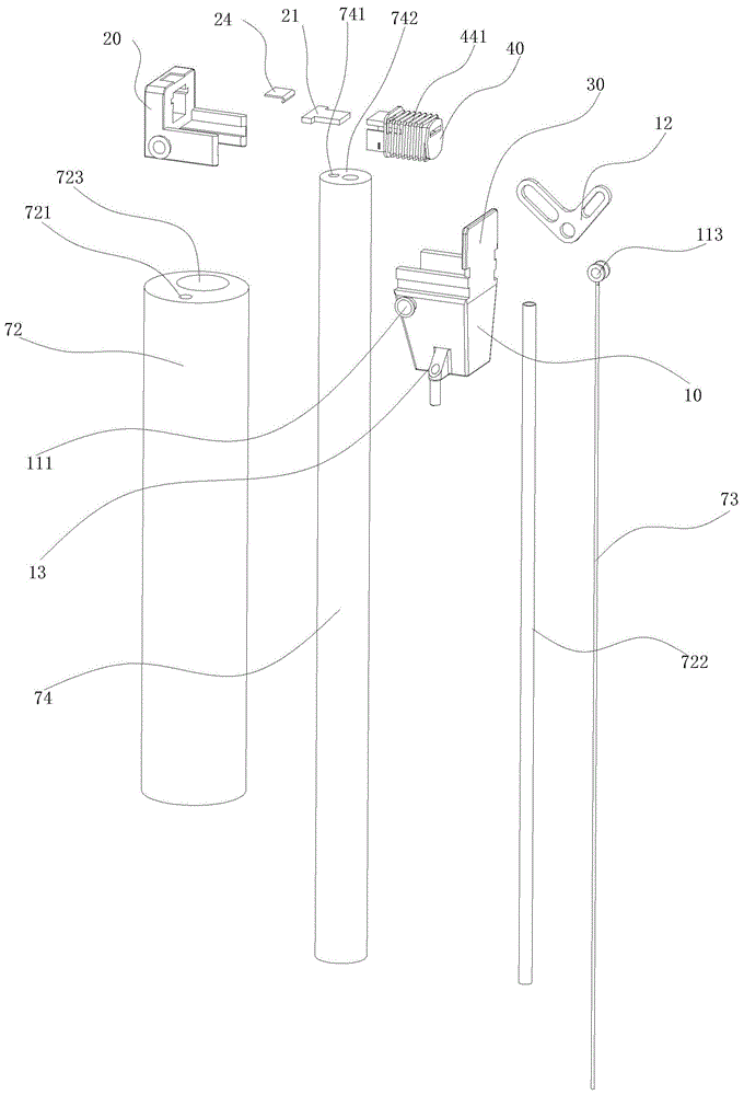
FIG. 1 is an exploded view of a staple line assembly according to one embodiment of the present invention;
FIG. 2 is an exploded view of a staple stapler according to one embodiment of the present invention;
FIG. 3 is a view showing the state of the staple stapler as it enters the digestive tract, according to one embodiment of the present invention;
FIG. 4 is a cross-sectional view of a staple stapler as it enters the alimentary tract, in accordance with one embodiment of the present invention;
FIG. 5 is a view of a staple stapler shown open in accordance with a first embodiment of the invention;
FIG. 6 is a cross-sectional view of a staple stapler shown open in accordance with a first embodiment of the invention;
FIG. 7 is a view showing the state of the staple stapler during suturing in accordance with one embodiment of the present invention;
FIG. 8 is a cross-sectional view of a staple stapler during stapling in accordance with one embodiment of the present invention;
FIG. 9 is a block diagram of a staple within a staple holder according to one embodiment of the present invention;
FIG. 10 is a cross-sectional view of a staple within a staple holder according to one embodiment of the present invention;
FIG. 11 is a structural diagram of a first colliding member according to the first embodiment of the present invention (excluding the pressing portion);
fig. 12 is a structural view of the second colliding element and the seat body according to the first embodiment of the disclosure;
FIG. 13 is a block diagram of a staple containing member in accordance with one embodiment of the present invention;
FIG. 14 is a structural diagram of an inner seat according to a first embodiment of the present invention;
fig. 15 is a structural diagram of the pressing tongue piece according to the first embodiment of the invention;
FIG. 16 is a structural diagram of an elastic hook according to a first embodiment of the present invention;
FIG. 17 is a block diagram of a staple prior to stapling in accordance with one embodiment of the present invention;
FIG. 18 is a block diagram of a staple after it has been stapled in accordance with a first embodiment of the present invention;
FIG. 19 is a structural view of a locking member in accordance with a first embodiment of the present invention;
FIG. 20 is a structural view of a transmission member according to a first embodiment of the present invention;
FIG. 21 is an exploded view of a staple seaming assembly according to a second embodiment of the present invention;
FIG. 22 is an exploded view of a staple stapler according to a second embodiment of the invention;
FIG. 23 is a view showing the state of the staple stapler as it enters the digestive tract in accordance with the second embodiment of the present invention;
FIG. 24 is a cross-sectional view of a staple stapler as it enters the alimentary tract, in accordance with a second embodiment of the present invention;
FIG. 25 is a view of the stapler in an open state, in accordance with a second embodiment of the invention;
FIG. 26 is a cross-sectional view of a staple stapler shown open, in accordance with a second embodiment of the invention;
FIG. 27 is a view showing the state of the staple stapler during suturing in accordance with the second embodiment of the present invention;
FIG. 28 is a cross-sectional view of the stapler during suturing in accordance with a second embodiment of the present invention;
FIG. 29 is a structural view of the first elastic member and the nail accommodating member according to the second embodiment of the present invention;
FIG. 30 is a cross-sectional view of the first resilient element and the staple containing element in accordance with a second embodiment of the present invention;
FIG. 31 is a structural view of a first striker (with a pressing portion removed) according to a second embodiment of the present invention;
FIG. 32 is a block diagram of a staple containing member in accordance with a second embodiment of the present invention;
FIG. 33 is an exploded view of a third embodiment of the present invention, showing a staple fastening device;
FIG. 34 is an exploded view of a staple stapler according to a third embodiment of the invention;
FIG. 35 is a view showing the state of the staple stapler after it has entered the digestive tract in accordance with the third embodiment of the present invention;
FIG. 36 is a cross-sectional view of a staple stapler as it enters the alimentary tract, in accordance with a third embodiment of the present invention;
FIG. 37 is a view of the third embodiment of the present invention showing the stapler in an open state;
FIG. 38 is a cross-sectional view of a staple stapler, in accordance with a third embodiment of the invention, as it is opened;
FIG. 39 is a view showing the state of the staple stapler during suturing in accordance with the third embodiment of the present invention;
FIG. 40 is a cross-sectional view of a staple stapler during stapling in accordance with a third embodiment of the present invention;
FIG. 41 is a schematic view of the first resilient member and the nail receiving member according to the third embodiment of the present invention;
FIG. 42 is a cross-sectional view of the first resilient element and the staple containing member in a third embodiment of the present invention;
FIG. 43 is a structural view of a first striker (with a pressing portion removed) in the third embodiment of the present invention;
fig. 44 is a structural view of the second colliding member and the seat body in the third embodiment of the present invention;
FIG. 45 is a block diagram of a clamping head positioned in the chuck receiving member according to a third embodiment of the present invention;
FIG. 46 is a structural view of a staple according to a third embodiment of the present invention;
FIG. 47 is a view showing the construction of a clamping head in accordance with the third embodiment of the present invention;
description of reference numerals:
10. a base body 111, a first pin shaft 112, a second pin shaft 113, a third pin shaft 12, a transmission piece 120, a shaft hole 121, a force application part 122, a first sliding groove 123, a force transmission part 124, a second sliding groove 13, a limiting piece 131, a limiting hole 14 and a fixed jack,
20. a first colliding piece, 201, an end plate, 2010, a fixing groove, 2011, a containing groove, 2012, a yielding groove, 202, a side arm, 21, a pressing tongue piece, 211, a side wing, 212, a pressing part, 24, an elastic clamping hook, 241, a fixing end, 242 and an elastic hook,
30. a second butting piece 31, a nail body sewing part 32 and a clamping groove,
40. the nail containing piece 401, the nail body containing space 411, the outer frame body 412, the inner seat 413, the locking piece 4131, the elastic locking head 414, the locking hole 421, the top plate 422, the bottom plate 423, the side plate 424, the limiting plate 431, the pressing window 432, the sewing window 441, the first elastic piece 442, the second elastic piece 45 and the light through hole,
51. the linear guide, 52, the linear guide groove,
60. staple, 611, connecting piece, 612, nail plate, 62, nail body, 621, limit part, 63, clamping head, 631, insertion opening, 632, elastic clamping piece, 64, chuck containing piece, 641, third elastic piece, 642, fixing plate, 643, movable plate, 644, limit baffle, 645, clamping plate,
72. a guide tube, 721, a first guide lumen, 722, an inner catheter, 723, a second guide lumen, 73, a push-pull member, 74, an inner tube, 741, a lens, 742, an endoscope lumen.
Detailed Description
In order to facilitate an understanding of the invention, specific embodiments thereof will be described in more detail below with reference to the accompanying drawings.
Unless specifically stated or otherwise defined, all technical and scientific terms used herein have the same meaning as commonly understood by one of ordinary skill in the art to which this invention belongs. In the case of a real-world scenario incorporating the technical solution of the present invention, all technical and scientific terms used herein may also have meanings corresponding to the purpose of achieving the technical solution of the present invention.
As used herein, unless otherwise specified or defined, "first" and "second" … are used merely for name differentiation and do not denote any particular quantity or order.
As used herein, the term "and/or" includes any and all combinations of one or more of the associated listed items, unless specified or otherwise defined.
It will be understood that when an element is referred to as being "secured to" another element, it can be directly secured to the other element or intervening elements may also be present; when an element is referred to as being "connected" to another element, it can be directly connected to the other element or intervening elements may also be present; when an element is referred to as being "mounted on" another element, it can be directly on the other element or intervening elements may also be present. When an element is referred to as being "on" another element, it can be directly on the other element or intervening elements may also be present.
As used herein, unless otherwise specified or defined, the terms "comprises," "comprising," and "comprising" are used interchangeably to refer to the term "comprising," and are used interchangeably herein.
It is needless to say that technical contents or technical features which are contrary to the object of the present invention or clearly contradicted by the object of the present invention should be excluded.
Example one
As shown in fig. 1 to 20, the nail-shaped suturing device according to the present embodiment is mainly used for suturing the digestive tract, and includes a guide tube, an endoscopic tube 74 and a nail-shaped suturing device, wherein the guide tube 72 has a first guide cavity 721 and a second guide cavity 723, an inner catheter 722 is disposed in the first guide cavity 721, a push-pull member 73 is disposed in the inner catheter 722, the endoscopic tube 74 is disposed in the second guide cavity, the holder body is mounted at the front end of the endoscopic tube 74, and the front end of the push-pull member 73 is engaged with the force application portion of the transmission member.
In this embodiment, the push-pull member 73 is made of a guide wire having a certain elasticity and rigidity, and the endoscope tube 74 is built in the second guide cavity 723. The guide tube 72 is flexible, can be bent and is not easy to deform, and can be integrally formed by a high-elasticity material, or a pipeline embedded with a spring, or other pipeline parts meeting the requirement of elastic performance. The first guide cavity 721 functions as a guide and a limit, and is configured to allow the push-pull member 73 to be bent in a flexible manner in a bending state, thereby effectively transmitting a pushing force.
The front end of the endoscope tube 74 is inserted into the fixing insertion hole 14 of the base 10 of the nail-shaped suturing device, and can be connected with the base 10 of the nail-shaped suturing device through interference fit or other connecting pieces, and other cavities can be arranged in the endoscope tube 74 according to requirements, such as transmission of images, or transportation of gas or liquid.
The following describes the staple stapler in detail:
the nail-shaped stitching instrument comprises a seat body 10, a first butting piece 20, a second butting piece 30 and a nail accommodating piece 40, wherein the size of the lower part of the seat body 10 is reduced to form an inverted frustum shape so as to reduce the volume of the seat body 10 and make corners blunt, the nail-shaped stitching instrument can conveniently enter a human body lumen safely, and the first butting piece 10 and the second butting piece 30 are arranged on the seat body 10; a first guide mechanism is arranged between the first colliding member 20 and the seat body 10, and the first colliding member 20 is movably arranged on the seat body 10 through the first guide mechanism, so that the first colliding member 20 and the second colliding member 30 move close to or away from each other; the nail accommodating part 40 is movably arranged in the accommodating groove 2011 of the first colliding part 20, and a second guide mechanism is arranged between the nail accommodating part 40 and the first colliding part 20; the first guide mechanism and the second guide mechanism are both linear guide mechanisms, and the guide directions of the linear guide mechanisms are parallel. The nail accommodating part 40 is provided with an accommodating space 401 of the nail body 62, the nail accommodating part 40 is provided with a pressing window 431 and a sewing window 432 which are communicated with the accommodating space, the first colliding part 20 is provided with a pressing part 212, the pressing part 212 is opposite to the pressing window 431, the second colliding part 30 is provided with a sewing part 31 of the nail body 62, and the sewing window 432 is opposite to the sewing part 31 of the nail body 62.
When suturing, the nail-shaped suturing device is placed at the position of the human tissue to be sutured, and the human tissue to be sutured is positioned between the first pair of colliding pieces 20 and the second pair of colliding pieces 30; the first colliding element 20 is translated towards the other direction under the action of external force; the staples 60 are bent after penetrating the human tissue to be sutured by the colliding action of the first colliding member 20 and the second colliding member 30, and are sutured to the human tissue to be sutured. The nail-shaped suturing device can be used for quickly suturing the digestive tract of a human body, is very convenient to use, and can be used in combination with the endoscope tube 74 to achieve the minimally invasive effect. In this embodiment, since the first colliding member 20 is guided by the first linear guide mechanism and the second linear guide mechanism, the first colliding member 20 moves in a translational manner when moving, so that the deviation of the human tissue can be reduced, the suturing precision and reliability are high, the implementation effect is as in the case of the surgical open surgery and the hard endoscope, the defective wound surface is quickly and firmly closed by the metal staple, and the suturing effect is also ensured.
In this embodiment, the first linear guide mechanism includes a first linear guide portion and a second linear guide portion, and the first linear guide portion and the second linear guide portion are used for linear translational guiding between the first colliding member 20 and the seat body 10, and may adopt a manner of matching a linear guide groove with a linear guide rail, or adopt a linear guide rod or other manners for guiding; in order to improve the guiding precision, a plurality of linear guide grooves and linear guide rails can be matched. In this embodiment, the first linear guide portion and the second linear guide portion are a linear guide rail 51 and a linear guide groove 52 which are matched with each other; the first linear guide portions are located on two opposite outer side surfaces of the seat body 10, the first colliding member 20 includes an end plate 201 and side arms 202 located on two sides of the end plate 201, and the second linear guide portions are located on inner side surfaces of the two side arms 202.
The translation of the first colliding member 20 is controlled by the pushing and pulling member 73, in this embodiment, a first pin 111 is disposed on the seat body 10, a shaft hole 120 is disposed on the transmission member 12, the transmission member 12 is movably mounted on the first pin 111 through the shaft hole 120, the transmission member 12 is an L-like rod member, the front end of the transmission member is a force application portion 121, the rear end of the transmission member is a force transmission portion 123, the force application portion 121 and the force transmission portion 123 are respectively provided with a first sliding slot 122 and a second sliding slot 124, the transmission member 12 is movably mounted on the seat body 10 through the first pin 111, the front end of the pushing and pulling member 73 is provided with a third pin 113, the third pin 113 is in sliding fit with the first sliding slot 122, the first colliding member 20 is provided with a second pin 112, and the second pin 112 is in sliding fit with the second sliding slot 124. In this embodiment, the driving member 12 is driven to rotate by the pushing and pulling member 73, so that the pushing or pulling longitudinal translational motion of the pushing and pulling member 73 along the inner lens tube 74 is converted into the transverse translational motion of the first colliding member 20, so that the suturing nail 60 can accurately puncture the tissue to be sutured, and the suturing of the human tissue is realized.
In order to reduce the swing of the push-pull member 73 and improve the sewing precision, the base 10 is connected with a limiting member 13, the limiting member 13 is provided with a limiting hole 131, the front end of the inner conduit 722 is limited by the limiting hole 131, and the transverse swing of the push-pull member 73 is reduced.
In this embodiment, the guide tube 72 is separately processed and used in cooperation with the endoscope tube 74, and a corresponding first guide cavity 721 may be provided in the endoscope tube 74; it will be appreciated that the guide tube 72 and the endoscope tube 74 may be integrally fixed by a strap or the like. Depending on the application, the guide tube 72 may be combined with the stapling instrument to perform the stapling function without the need for cooperation with the endoscope tube 74.
It should be noted that:
in the present invention, when the pushing and pulling member 73 drives the first colliding member 20 to translate, the transmission structure is not limited to the foregoing manner, and it is understood that other similar structures can also be used to implement the translation of the first colliding member 20 relative to the second colliding member 30, and suture the human tissue through the suturing nail 60, which is within the protection scope of the present application.
Please refer to fig. 2, 9-19, in this embodiment, the suturing nail 60 is approximately n-shaped, and includes a connecting piece 611 and two nail bodies 62 mounted at both side ends of the connecting piece 611, the nail tips of the two nail bodies 62 face forward, when suturing, the first striker 20 drives the suturing nail 60 to strike against the second striker 30, and bends the nail body 62 of the suturing nail 60, and the nail tip returns to the connecting piece 611 after bending, and the connecting piece 611 can block the nail tip to prevent the nail tip from damaging the human tissue again. For the installation of convenient pair sewing nail 60, avoid sewing nail 60 skew, crooked or drop appearing sewing the in-process first butt on 20 gliding nail holding member 40 that is provided with, nail holding member 40 with first butt is provided with second guiding mechanism between 20, and it includes third straight line guide portion, fourth straight line guide portion, third straight line guide portion set up in first butt on 20, fourth straight line guide portion set up in on the nail holding member 40, third straight line guide portion and fourth straight line guide portion cooperate. The staple holder 40 and the second guide mechanism are described in detail below.
In this embodiment, two fixing grooves 2010 are formed in the end plate 201 of the first striker 20, as shown in fig. 15, two side wings 211 of the pressing tongue piece 21 are respectively inserted into the fixing grooves 2010 and fixed, the front end of the pressing tongue piece 21 forms the pressing portion 212, and both sides thereof form the linear guide 51.
The nail accommodating part 40 comprises an outer frame 411 and an inner seat 412, the nail accommodating part 40 is entirely square, and comprises a top plate 421, a bottom plate 422 and two side plates 423, the top plate 421 is located above the bottom plate 422, the top plate 421 and the bottom plate 422 are respectively connected by the two side plates 423, the two side plates 423 are respectively provided with the guide grooves, the guide grooves form the linear guide grooves 52, two sides (namely the linear guide rails 51) of the pressing tongue piece 21 are clamped into the linear guide grooves 52 and are in sliding fit with the linear guide grooves 52 to form the second guide mechanism, a square first elastic piece 441 is arranged outside the nail accommodating part 40, the first elastic piece 441 is a spiral spring, two ends of the nail accommodating part 40 are respectively provided with a limiting plate 424, the first butting part 20 is provided with an elastic hook 24, and a fixed end 241 of the elastic hook 24 is fixed in a fixing groove 2010 of the first butting part 20, elastic hook part 242 is equipped with to elasticity trip 24 outer end, nail holder 40 is spacing through this elasticity trip 24's elasticity hook part 242, avoids nail holder 40 is deviate from at will, after breaking off elasticity hook part 242 off, can with nail holder 40 takes out.
The inner seat 412 includes a fixed plate 642 at the bottom and a movable plate 643 above the fixed plate 642, a second elastic element 442 is disposed between the fixed plate 642 and the movable plate 643, and a limit baffle 644 for limiting the movable plate 643 is disposed at the side of the fixed plate 642 and the movable plate 643, in this embodiment, the number of the staples 60 is at least two, and the staples are disposed on the movable plate 643 in an up-and-down overlapping direction, the staples 60 include a connecting piece 611 and a staple body 62 fixed on the connecting piece 611, and under the action of the second elastic element 442, the staples 60 are held up, so that the front ends of the staples 60 are aligned with the staple window 432, and the rear ends of the staples are aligned with the pressing window 431; after one stitch is made, the lower staples 60 are lifted for a second stitch, and so on. The outer frame 411 is provided with a locking hole 414, and the inner seat 412 is locked with the outer frame 411 by two elastic locking heads 4131 on the locking piece 413.
Please refer to fig. 3 to 18, which illustrate the following steps when suturing human tissue:
as shown in fig. 3 and 4, the first colliding member 20 is located at a position longitudinally flush with the seat body 10 by controlling the pushing and pulling member 73, which is an insertion state of the staple stapler having a small transverse dimension for easy insertion thereof, thereby preventing the staple stapler from scratching the mucosal tissue of the lumen of the digestive tract.
As shown in fig. 5 and 6, the first colliding member 20 is located at the outer side position by controlling the pushing and pulling member 73, and the suturing nail 60 is horizontally placed, which is the opened state of the staple stapler, the lateral dimension of the staple stapler is large, so that the clamping operation of the clamp to the human tissue to be sutured can be facilitated, enough space is left for the translation of the first colliding member 20, and the human tissue to be sutured can be clamped and pulled to the area between the first colliding member 20 and the second colliding member 30 by the clamp or the like.
As shown in fig. 7 and 8, in the suturing state of the staple stapler, when the first operating element is operated to make the first pair of striking members 20 translate rapidly inward and drive the staple containing member 40 (and the staples 60 therein) to strike the second pair of striking members 30, when the tissue to be sutured between the first pair of striking members 20 and the second pair of striking members 30 contacts with the staple containing member 40 and abuts against each other, the movement of the staple containing member 40 relative to the second pair of striking members 30 is stopped, and at the same time, the first elastic member 441 is compressed, so that the staple containing member 40 moves backward relative to the first pair of striking members 20. The first striker 20 and the pressing tongue 21 fixed thereon continue to move forward relative to the second striker 30, and the first elastic member 441 is compressed to provide a buffer effect and balance the entire suturing process, and the pressing tongue 21 pushes the suturing nail 60 out of the nail accommodating member 40 gradually as the pressing tongue 21 continues to advance.
As shown in fig. 12, in order to ensure effective bending of the tips of the staples 60 during the suturing, the second striker 30 is provided with two concave arcs and two convex arcs on the inner side thereof, which are preferably located on both sides of the convex arcs and guide the tips of the two bodies 62 of the staples 60 to be bent toward the middle. The staple 60 bends the tip of the staple 60 at the staple portion 31 of the staple body 62, thereby achieving the effect of suturing the human tissue.
After the first suture is completed, the first colliding member 20 and the second colliding member 30 move away from each other, and the compressed first elastic member 441 recovers to drive the staple containing member to recover to the original state, so that the new suture staples in the staple containing member 40 are pushed up by the second elastic member 442 into the pressing window to be sutured next time.
The three states described above are not necessarily the states in which the staple suturing device of the present embodiment is used, such as: in the insertion state, the first striker 20 may be located slightly inside the housing 10.
The embodiment has the following advantages:
when the human tissue is sutured, the nail-shaped suturing device is firstly sent to the human tissue to be sutured through the guide tube 72 and the endoscope tube 74 therein, and then the human tissue is sutured through the nail-shaped suturing device, so that minimally invasive surgery can be realized, and the damage to the human tissue is reduced; when suturing is performed, the suturing nail 60 is placed in the nail accommodating part 40, in an initial suturing state, the suturing nail 60, the nail accommodating part 40 and the first colliding piece 20 do not move relatively, after colliding with the human tissue to be sutured and the second colliding piece 30, the first elastic piece 441 is gradually compressed, so that the nail accommodating part 40 moves backwards relative to the first colliding piece 20 (and the pressing part 212 thereon) and the suturing nail 60 in the pressing window 431, and the first colliding piece 20 (and the pressing part 212 thereon) and the suturing nail 60 in the pressing window 431 continuously collide with the tissue to be sutured and the second colliding piece 30, so that the suturing nail 60 is gradually ejected out of the suturing window 432 from the pressing window 431 through the pressing part 212 and penetrates the human tissue to be sutured, and the human tissue is sutured. In the suturing process, the suturing nail is always positioned in the abutting window 431 of the nail accommodating piece 40, the suturing nail 60 is always shielded and protected by the nail accommodating piece 40, deviation caused by extrusion of suturing tissues can be avoided, smooth movement can be realized, deflection and clamping stagnation of the suturing nail 60 in the suturing process are reduced, and the suturing effect is more accurate. At the end of suturing, the first and second colliding members 20 and 30 move away from each other, and the compressed first elastic member 441 recovers to drive the nail accommodating member 40 to recover, so that the new suturing nail 60 located in the nail accommodating member 40 enters the abutting window 431 to be sutured next time. The continuous sewing effect of the multi-sewing nail is well solved, and the sewing efficiency is improved.
Example two
As shown in fig. 21-32, in the present embodiment, a single staple 60 is accommodated in the staple accommodating member 40, and the principle is the same as that of the first embodiment, which will not be described herein again.
Please refer to fig. 29, 30 and 32, in this embodiment, the nail holder 40 of this embodiment is of an integral structure, and the whole nail holder is square, and includes a top plate 421, a bottom plate 422 and two side plates 423, the two side plates 423 connect the top plate 421 and the bottom plate 422 respectively, the two side plates 423 are respectively provided with the guide slots, the stitching nail 60 is located in the space surrounded by the top plate 421, the bottom plate 422 and the two side plates 423, in this embodiment, components such as an inner seat are omitted, compared with the first embodiment, and the structure of the nail holder 40 is simpler.
Further, the nail holder 40 is provided with a light transmitting hole 45 vertically penetrating therethrough, and a lens 741 at the distal end of the endoscope 74 faces the light transmitting hole 45 to view a forward visual field for observing the state of the operation. An endoscope cavity 742 is also provided in the endoscope tube 74, and an operation cable can be provided in the endoscope cavity 742, and the operation cable can control a clamp or the like at the front end of the holder body 10.
EXAMPLE III
As shown in fig. 33 to 47, in the present embodiment, the staple 60 has different structures, and in the present embodiment, the staple 60 further includes a clamping head 63, an elastic clip is disposed in the clamping head 63, the nail body 62 has a limiting portion 621, the nail body 62 corresponds to the clamping head 63, the clamping head 63 is mounted on the suture portion 31 of the nail body 62, and the nail tip of the nail body 62 faces the clamping head 63.
In contrast, a collet holder is provided on the second striker 30, and a collet receiving space is provided inside the collet holder, in which the clamping head 63 is disposed. Specifically, the cartridge holder includes a fixed plate 642 at the bottom and a movable plate 643 above the fixed plate 642, a third elastic member 641 is disposed between the fixed plate 642 and the movable plate 643, a limit stopper 644 for limiting the movable plate 643 is disposed at the side of the fixed plate 642 and the movable plate 643, a plurality of clamping heads 63 are disposed on the movable plate 643 in an up-and-down overlapping manner, after the nail tip is inserted into the clamping head 63, the limit portion 621 at the front end is clamped by the elastic clip of the clamping head 63 to achieve the effect of suturing, and after the first suturing, the second lower clamping head 63 is held up by the third elastic member 641 to perform the next suturing operation.
This embodiment the sewing needle is T style of calligraphy structure, and it includes nail board 612 and the nail body 62 that is located nail board 612 front end, nail body 62 front end is provided with spacing portion 621, press from both sides and be equipped with the inserted hole on the tight head 63, work as the front end of nail body 62 inserts press from both sides tight head 63 back, the spacing portion 621 of the nail body 62 is by the chucking of elastic clamping piece, and reach sutural effect.
In this embodiment, since the staple 60 is not bent during the suturing process, a sufficient stroke needs to be ensured during the suturing process, and the receding groove 2012 is formed inside the baffle of the first striker 20.
The clamping structure of the chuck accommodating part in the embodiment is as follows: the second colliding member 30 is provided with a catching groove 32, and the cartridge receiver has a catching plate 645 at a back side thereof, and both sides of the catching plate 645 are slidably caught in the catching groove 32 of the second colliding member 30.
The above embodiments are provided to illustrate, reproduce and deduce the technical solutions of the present invention, and to fully describe the technical solutions, the objects and the effects of the present invention, so as to make the public more thoroughly and comprehensively understand the disclosure of the present invention, and not to limit the protection scope of the present invention.
The above examples are not intended to be exhaustive of the invention and there may be many other embodiments not listed. Any alterations and modifications without departing from the spirit of the invention are within the scope of the invention.