CN113478715B - Particle board forming device - Google Patents
Particle board forming device Download PDFInfo
- Publication number
- CN113478715B CN113478715B CN202110635923.4A CN202110635923A CN113478715B CN 113478715 B CN113478715 B CN 113478715B CN 202110635923 A CN202110635923 A CN 202110635923A CN 113478715 B CN113478715 B CN 113478715B
- Authority
- CN
- China
- Prior art keywords
- hopper
- vibration
- cavity mold
- guide rail
- plate
- Prior art date
- Legal status (The legal status is an assumption and is not a legal conclusion. Google has not performed a legal analysis and makes no representation as to the accuracy of the status listed.)
- Active
Links
Images


Classifications
-
- B—PERFORMING OPERATIONS; TRANSPORTING
- B29—WORKING OF PLASTICS; WORKING OF SUBSTANCES IN A PLASTIC STATE IN GENERAL
- B29C—SHAPING OR JOINING OF PLASTICS; SHAPING OF MATERIAL IN A PLASTIC STATE, NOT OTHERWISE PROVIDED FOR; AFTER-TREATMENT OF THE SHAPED PRODUCTS, e.g. REPAIRING
- B29C43/00—Compression moulding, i.e. applying external pressure to flow the moulding material; Apparatus therefor
- B29C43/02—Compression moulding, i.e. applying external pressure to flow the moulding material; Apparatus therefor of articles of definite length, i.e. discrete articles
- B29C43/04—Compression moulding, i.e. applying external pressure to flow the moulding material; Apparatus therefor of articles of definite length, i.e. discrete articles using movable moulds
- B29C43/06—Compression moulding, i.e. applying external pressure to flow the moulding material; Apparatus therefor of articles of definite length, i.e. discrete articles using movable moulds continuously movable in one direction, e.g. mounted on chains, belts
-
- B—PERFORMING OPERATIONS; TRANSPORTING
- B29—WORKING OF PLASTICS; WORKING OF SUBSTANCES IN A PLASTIC STATE IN GENERAL
- B29C—SHAPING OR JOINING OF PLASTICS; SHAPING OF MATERIAL IN A PLASTIC STATE, NOT OTHERWISE PROVIDED FOR; AFTER-TREATMENT OF THE SHAPED PRODUCTS, e.g. REPAIRING
- B29C43/00—Compression moulding, i.e. applying external pressure to flow the moulding material; Apparatus therefor
- B29C43/32—Component parts, details or accessories; Auxiliary operations
- B29C43/34—Feeding the material to the mould or the compression means
- B29C2043/3405—Feeding the material to the mould or the compression means using carrying means
- B29C2043/3427—Feeding the material to the mould or the compression means using carrying means hopper, vessel, chute, tube, conveying screw, for material in discrete form, e.g. particles or powder or fibres
-
- B—PERFORMING OPERATIONS; TRANSPORTING
- B29—WORKING OF PLASTICS; WORKING OF SUBSTANCES IN A PLASTIC STATE IN GENERAL
- B29C—SHAPING OR JOINING OF PLASTICS; SHAPING OF MATERIAL IN A PLASTIC STATE, NOT OTHERWISE PROVIDED FOR; AFTER-TREATMENT OF THE SHAPED PRODUCTS, e.g. REPAIRING
- B29C43/00—Compression moulding, i.e. applying external pressure to flow the moulding material; Apparatus therefor
- B29C43/32—Component parts, details or accessories; Auxiliary operations
- B29C43/34—Feeding the material to the mould or the compression means
- B29C2043/3444—Feeding the material to the mould or the compression means using pressurising feeding means located in the mould, e.g. plungers or pistons
-
- B—PERFORMING OPERATIONS; TRANSPORTING
- B29—WORKING OF PLASTICS; WORKING OF SUBSTANCES IN A PLASTIC STATE IN GENERAL
- B29C—SHAPING OR JOINING OF PLASTICS; SHAPING OF MATERIAL IN A PLASTIC STATE, NOT OTHERWISE PROVIDED FOR; AFTER-TREATMENT OF THE SHAPED PRODUCTS, e.g. REPAIRING
- B29C43/00—Compression moulding, i.e. applying external pressure to flow the moulding material; Apparatus therefor
- B29C43/32—Component parts, details or accessories; Auxiliary operations
- B29C43/34—Feeding the material to the mould or the compression means
- B29C2043/3488—Feeding the material to the mould or the compression means uniformly distributed into the mould
- B29C2043/3494—Feeding the material to the mould or the compression means uniformly distributed into the mould using vibrating means
-
- B—PERFORMING OPERATIONS; TRANSPORTING
- B29—WORKING OF PLASTICS; WORKING OF SUBSTANCES IN A PLASTIC STATE IN GENERAL
- B29K—INDEXING SCHEME ASSOCIATED WITH SUBCLASSES B29B, B29C OR B29D, RELATING TO MOULDING MATERIALS OR TO MATERIALS FOR MOULDS, REINFORCEMENTS, FILLERS OR PREFORMED PARTS, e.g. INSERTS
- B29K2105/00—Condition, form or state of moulded material or of the material to be shaped
- B29K2105/25—Solid
- B29K2105/251—Particles, powder or granules
-
- B—PERFORMING OPERATIONS; TRANSPORTING
- B29—WORKING OF PLASTICS; WORKING OF SUBSTANCES IN A PLASTIC STATE IN GENERAL
- B29L—INDEXING SCHEME ASSOCIATED WITH SUBCLASS B29C, RELATING TO PARTICULAR ARTICLES
- B29L2007/00—Flat articles, e.g. films or sheets
- B29L2007/002—Panels; Plates; Sheets
-
- Y—GENERAL TAGGING OF NEW TECHNOLOGICAL DEVELOPMENTS; GENERAL TAGGING OF CROSS-SECTIONAL TECHNOLOGIES SPANNING OVER SEVERAL SECTIONS OF THE IPC; TECHNICAL SUBJECTS COVERED BY FORMER USPC CROSS-REFERENCE ART COLLECTIONS [XRACs] AND DIGESTS
- Y02—TECHNOLOGIES OR APPLICATIONS FOR MITIGATION OR ADAPTATION AGAINST CLIMATE CHANGE
- Y02E—REDUCTION OF GREENHOUSE GAS [GHG] EMISSIONS, RELATED TO ENERGY GENERATION, TRANSMISSION OR DISTRIBUTION
- Y02E50/00—Technologies for the production of fuel of non-fossil origin
- Y02E50/30—Fuel from waste, e.g. synthetic alcohol or diesel
Landscapes
- Engineering & Computer Science (AREA)
- Mechanical Engineering (AREA)
- Press-Shaping Or Shaping Using Conveyers (AREA)
- Casting Or Compression Moulding Of Plastics Or The Like (AREA)
- Dry Formation Of Fiberboard And The Like (AREA)
Abstract
本发明公开了一种微粒板材成型装置,通过型腔模具成型微粒材料板材,产品的尺寸、形位误差得到明显改善提升,通过布料机构与型腔模具的配合可调节布置于型腔模具内的凝胶颗粒量,保证微粒产品制作的材料用量,批次产品重量均衡、一致性好,布料机构布料的同时能够抹平凝胶颗粒表面;通过振动成型机构对凝胶颗粒振压成型,能充分的对微粒材料均匀的下压,保证产品的密实度,产品质量高;凝胶颗粒一次布料于型腔模具内,减少了凝胶颗粒布置次数,加固网直接压入凝胶颗粒层中,减化了微粒材料的生产动作,提高了生产效率;在成型后即将托板和微粒产品从型腔模具中取出,减少了型腔模具的投入数量,方便型腔模具运转,快速流水作业。

The invention discloses a particle plate molding device, which can form a particle material plate through a cavity mold, and the size and shape error of the product can be significantly improved. The amount of gel particles ensures the amount of materials used in the production of particle products. The weight of batches of products is balanced and the consistency is good. Evenly press down on the particulate material to ensure the compactness of the product and high product quality; the gel particles are placed in the cavity mold at one time, reducing the number of gel particle arrangements, and the reinforcement net is directly pressed into the gel particle layer, reducing the The production action of granular materials is simplified, and the production efficiency is improved; after forming, the pallet and granular products are taken out of the cavity mold, which reduces the input quantity of the cavity mold, facilitates the operation of the cavity mold, and facilitates fast flow operation.
Description
技术领域technical field
本发明涉及微粒板材领域,特别是涉及一种微粒板材成型装置。The invention relates to the field of particle sheets, in particular to a particle sheet forming device.
背景技术Background technique
现有微粒板材的制作,是将特定目数的吸声颗粒与胶凝合剂搅拌均匀形成凝胶颗粒,然后先将1/2型腔厚度凝胶颗粒布置于成型型腔中,通过人工手工刮平方式将凝胶颗粒布置均匀,其次在凝胶颗粒上放置加固网,再布置剩余1/2型腔厚度凝胶颗粒,通过人工拍打击使产品密实,将胶凝颗粒刮置平整,使用手工将其表面抹平,形成微粒板材。The production of the existing particle board is to stir the sound-absorbing particles of a specific mesh and the gelling agent to form gel particles evenly, and then first arrange the gel particles with a thickness of 1/2 cavity in the molding cavity, and scrape them manually Arrange the gel particles evenly in the flat method, then place a reinforcement net on the gel particles, and then arrange the gel particles with the remaining 1/2 cavity thickness, make the product dense by manual beating, scrape the gel particles flat, and use manual The surface is smoothed to form a particle sheet.
现有微粒板材的制作存在以下问题:The following problems exist in the production of existing particle boards:
布置凝胶颗粒时无法计量,每件微粒板材存在重量偏差,产品一致性差;It is impossible to measure when arranging gel particles, and there is a weight deviation for each particle sheet, resulting in poor product consistency;
每件微粒板材拍击的频率、次数、力量均不一致,产品密度波动大,表面易出现疏松状,产品质量差;The frequency, times, and force of each particle sheet are inconsistent, the product density fluctuates greatly, the surface is prone to looseness, and the product quality is poor;
手工抹平每件微粒板材表面平整度波动范围较大;The surface roughness of each particle board has a large fluctuation range when smoothed by hand;
对操作人员技能水平要求较高,人工效率低下。The requirements for the skill level of the operators are high, and the labor efficiency is low.
发明内容Contents of the invention
本发明的目的在于:针对现有技术存在的问题,提供一种微粒板材成型装置。The purpose of the present invention is to provide a particle sheet forming device for the problems existing in the prior art.
为了实现上述目的,本发明采用的技术方案为:In order to achieve the above object, the technical scheme adopted in the present invention is:
一种微粒板材成型装置,包括:A particle sheet forming apparatus, comprising:
型腔模具,用于承载托板,并且布置凝胶颗粒以成型微粒板材;a cavity mold for carrying the pallet and arranging the gel particles to form the particle sheet;
托板转运机构,用于将所述托板安装到所述型腔模具中;pallet transfer mechanism for installing the pallet into the cavity mold;
布料机构,所述凝胶颗粒存放于所述布料机构中,所述布料机构用于在所述型腔模具中铺设并抹平所述凝胶颗粒,形成所述凝胶颗粒层;A distributing mechanism, the gel particles are stored in the distributing mechanism, and the distributing mechanism is used to lay and smooth the gel particles in the cavity mold to form the gel particle layer;
压入机构,所述凝胶颗粒层表面布置加固网,所述压入机构用于将所述加固网压入所述凝胶颗粒层厚度方向的中间位置;A press-in mechanism, a reinforcement net is arranged on the surface of the gel particle layer, and the press-in mechanism is used to press the reinforcement net into the middle position in the thickness direction of the gel particle layer;
振动成型机构,用于对所述型腔模具中的所述凝胶颗粒层振压到需求厚度,微粒板材成型;A vibration forming mechanism, used to vibrate the gel particle layer in the cavity mold to a required thickness, and form the particle sheet;
传送导轨,依次传输所述型腔模具至所述布料机构、所述压入机构和所述振动成型机构;Conveying guide rails, sequentially transporting the cavity mold to the distributing mechanism, the pressing mechanism and the vibration forming mechanism;
机架,设置所述传送导轨、所述托板转运机构、所述布料机构、所述压入机构和所述振动成型机构。The frame is provided with the transmission guide rail, the pallet transfer mechanism, the material distributing mechanism, the pressing mechanism and the vibration forming mechanism.
采用本发明所述的一种微粒板材成型装置,通过所述型腔模具成型微粒材料板材,产品的尺寸、形位误差得到明显改善提升,通过所述布料机构与所述型腔模具的配合可调节布置于所述型腔模具内的所述凝胶颗粒量,保证微粒产品制作的材料用量,批次产品重量均衡、一致性好,所述布料机构布料的同时能够抹平所述凝胶颗粒表面;通过所述振动成型机构对所述凝胶颗粒振压成型,能充分的对微粒材料均匀的下压,保证产品的密实度,产品质量高;所述凝胶颗粒一次布料于所述型腔模具内,减少了所述凝胶颗粒布置次数,所述加固网直接压入所述凝胶颗粒层中,减化了微粒材料的生产动作,提高了生产效率;在成型后即将所述托板和微粒产品从所述型腔模具中取出,减少了所述型腔模具的投入数量,方便所述型腔模具运转,快速流水作业,以便产业化;该装置使用简单,操作方便,效果良好。By adopting a particle sheet forming device according to the present invention, the particle material sheet is formed by the cavity mold, and the size and shape error of the product are significantly improved, and the cooperation between the material distribution mechanism and the cavity mold can Adjust the amount of the gel particles arranged in the cavity mold to ensure the amount of materials used in the production of particulate products, the weight of batch products is balanced and the consistency is good, and the distributing mechanism can smooth the gel particles while distributing surface; the gel particles are vibrated and formed by the vibration forming mechanism, which can fully and evenly press down on the particulate material to ensure the compactness of the product and high product quality; the gel particles are distributed on the mold at one time In the mold cavity, the number of times the gel particles are arranged is reduced, and the reinforcement net is directly pressed into the gel particle layer, which reduces the production action of the particulate material and improves production efficiency; Plates and particle products are taken out from the cavity mold, which reduces the input quantity of the cavity mold, facilitates the operation of the cavity mold, and facilitates fast flow operation for industrialization; the device is simple to use, easy to operate, and has good results .
优选地,所述托板转运机构包括滑块滑轨和与其滑动配合的滑块,所述滑块滑轨设于所述机架上,所述滑块上设有第一升降缸,所述第一升降缸连接转运夹具,所述转运夹具将所述托板转运到所述传送导轨上的所述型腔模具中。Preferably, the pallet transfer mechanism includes a slider slide rail and a slider slidingly fitted therewith, the slider slide rail is arranged on the frame, the slider is provided with a first lift cylinder, and the slider slide rail is provided on the frame. The first lifting cylinder is connected with a transfer fixture, and the transfer fixture transfers the pallet into the cavity mold on the transfer guide rail.
进一步优选地,所述第一升降缸带动所述转运夹具升降,所述转运夹具上设有真空吸盘或者电磁吸铁,所述真空吸盘或者电磁吸铁能够吸放吊运所述托板,定位好,速度快。Further preferably, the first lifting cylinder drives the transfer fixture to lift up and down, and the transfer fixture is provided with a vacuum chuck or an electromagnetic magnet, and the vacuum chuck or electromagnetic magnet can suck, release, lift the pallet, position OK, fast.
优选地,所述布料机构包括料斗滑轨、料斗和第一顶升部件,所述料斗滑轨和所述料斗滑动配合,所述料斗滑轨和所述第一顶升部件均连接于所述机架,所述传送导轨穿过所述料斗滑轨下方,所述第一顶升部件位于所述传送导轨处,所述第一顶升部件用于将所述型腔模具升降,所述料斗存放所述凝胶颗粒,所述料斗沿所述料斗滑轨移动时,将所述凝胶颗粒布置于所述型腔模具中。Preferably, the distributing mechanism includes a hopper slide rail, a hopper and a first jacking part, the hopper slide rail and the hopper are slidingly fitted, and the hopper slide rail and the first jacking part are both connected to the frame, the conveying guide rail passes under the hopper slide rail, the first jacking part is located at the conveying guide rail, the first jacking part is used to lift the cavity mold, and the hopper The gel particles are stored, and the gel particles are arranged in the cavity mold when the hopper moves along the hopper slide rail.
所述料斗沿所述料斗滑轨移动过程中,所述料斗中所述凝胶颗粒在自重作用下落入所述型腔模具,单位时间内所述料斗出料量基本恒定,通过所述第一顶升部件调节所述型腔模具内腔相对于所述料斗底部的高度大小,以此配合所述料斗移动速度大小,能够控制落入所述型腔模具中形成所述凝胶颗粒层的厚度。During the movement of the hopper along the slide rail of the hopper, the gel particles in the hopper fall into the cavity mold under the action of its own weight, and the discharge volume of the hopper is basically constant per unit time. The jacking part adjusts the height of the inner cavity of the cavity mold relative to the bottom of the hopper, so as to match the moving speed of the hopper, and can control the thickness of the gel particle layer falling into the cavity mold to form .
进一步优选地,所述料斗的布料宽度等于所述型腔模具内腔宽度,一次完成布料;或者所述料斗的布料宽度小于所述型腔模具内腔宽度,往复几次完成布料。Further preferably, the cloth width of the hopper is equal to the inner cavity width of the cavity mold, and the cloth is completed at one time; or the cloth width of the hopper is smaller than the inner cavity width of the cavity mold, and the cloth is completed by reciprocating several times.
进一步优选地,所述料斗底部设有下压角,所述下压角将布料后的所述凝胶颗粒层抹平。Further preferably, the bottom of the hopper is provided with a pressing angle, and the pressing angle smoothes the gel particle layer after the cloth.
采用这种结构,由于所述料斗下方的所述下压角在所述料斗移动过程中形成向下的压力,在由所述下压角倾斜铺设的所述凝胶颗粒,使得所述凝胶颗粒层铺设平整光滑,解决了现有技术布料表面呈波浪状的问题。With this structure, since the pressing angle below the hopper forms a downward pressure during the movement of the hopper, the gel particles laid obliquely by the pressing angle make the gel The particle layer is laid flat and smooth, which solves the problem that the cloth surface in the prior art is wavy.
进一步优选地,为保证出料后成型表面的光滑平整,所述料斗的尾部呈弧形。Further preferably, in order to ensure a smooth and even surface after discharge, the tail of the hopper is arc-shaped.
进一步优选地,所述料斗沿所述料斗滑轨运动方向的两侧分别设有所述下压角。Further preferably, the two sides of the hopper along the moving direction of the hopper slide rail are respectively provided with the press-down angles.
进一步优选地,所述料斗沿所述料斗滑轨运动方向的两侧分别设有挡料板,两个所述挡料板之间用于所述型腔模具通过,所述挡料板适配于所述料斗底部出料口,将所述凝胶颗粒封闭于所述料斗中。Further preferably, both sides of the hopper along the moving direction of the hopper slide rail are respectively provided with baffle plates, and the cavity mold is passed between the two baffle plates, and the material baffle plates are adapted to At the outlet at the bottom of the hopper, the gel particles are sealed in the hopper.
优选地,所述压入机构包括安装座、第二升降缸、第一导柱和梳形压板,所述机架上设置所述第一导柱,所述第一导柱连接所述安装座,所述安装座上设置所述第二升降缸,所述第二升降缸连接所述梳形压板,所述梳形压板滑动连接于所述第一导柱,所述传送导轨穿过所述梳形压板下方,所述梳形压板包括母板和若干条板,所述条板竖向设置,且其顶端连接于所述母板底部,所述条板的底端齐平,所述梳形压板将所述加固网压入所述凝胶颗粒层中。Preferably, the press-in mechanism includes a mounting seat, a second lifting cylinder, a first guide post and a comb-shaped pressing plate, the first guide post is provided on the frame, and the first guide post is connected to the mounting seat , the second lifting cylinder is arranged on the mounting seat, the second lifting cylinder is connected to the comb-shaped pressing plate, the comb-shaped pressing plate is slidably connected to the first guide column, and the transmission guide rail passes through the Below the comb-shaped pressing plate, the comb-shaped pressing plate includes a motherboard and several strips, the strips are vertically arranged, and their tops are connected to the bottom of the motherboard, the bottom ends of the strips are flush, and the combs A shaped press plate presses the reinforcing mesh into the layer of gel particles.
采用这种结构,所述第二升降缸带动所述梳形压板升降,所述梳形压板通过所述第一导柱导向,确保所述梳形压板移动路径的准确性,若干所述条板底端抵接在所述加固网上将其压入所述凝胶颗粒层,所述条板底端作用面积小,压强大,压入效果好,还能最大程度减小对所述凝胶颗粒层的破坏,以便后续对所述凝胶颗粒层压实。With this structure, the second lifting cylinder drives the comb-shaped pressing plate up and down, and the comb-shaped pressing plate is guided by the first guide column to ensure the accuracy of the moving path of the comb-shaped pressing plate. The bottom end is abutted against the reinforcement net to press it into the gel particle layer. The bottom of the slats has a small action area, strong pressure, good pressing effect, and can also minimize the impact on the gel particle layer. Layer destruction for subsequent compaction of the gel particle layer.
进一步优选地,所述条板之间间隔设置。Further preferably, the slats are arranged at intervals.
进一步优选地,所述压入机构还包括刮砂板和深度调节部件,所述刮砂板通过所述深度调节部件连接于所述机架,所述刮砂板滑动连接于所述第一导柱,所述刮砂板位于所述梳形压板和所述传送导轨之间,所述刮砂板上设有若干与所述条板一一对应的通孔,所述条板能够穿过所述通孔后抵接所述加固网,所述深度调节部件调节所述刮砂板的高度,以调节所述梳形压板将所述加固网压入所述凝胶颗粒层中的位置。Further preferably, the press-in mechanism further includes a sand scraper and a depth adjustment part, the sand scraper is connected to the frame through the depth adjustment part, and the sand scraper is slidably connected to the first guide column, the sand scraping plate is located between the comb-shaped pressing plate and the conveying guide rail, and the sand scraping plate is provided with a number of through holes corresponding to the strips one by one, and the strips can pass through the The through hole abuts against the reinforcing mesh, and the depth adjusting part adjusts the height of the sand scraping plate to adjust the position where the comb-shaped pressing plate presses the reinforcing mesh into the gel particle layer.
采用这种结构,所述条板在插入所述凝胶颗粒层后易粘附有所述凝胶颗粒,在所述第二升降缸提升所述梳形压板时,所述刮砂板将所述条板粘附的所述凝胶颗粒清理干净,所述深度调节部件能够根据需要制作的板厚来限制所述梳形压板下压至合适的位置,所述第一导柱确保所述条板准确进入所述通孔。With this structure, the gel particles are easily adhered to the strip plate after being inserted into the gel particle layer, and when the second lifting cylinder lifts the comb-shaped pressing plate, the sand scraping plate will The gel particles adhering to the strips are cleaned up, the depth adjustment part can limit the pressing of the comb-shaped pressing plate to a suitable position according to the required plate thickness, and the first guide post ensures that the strips board accurately into the through hole.
进一步优选地,所述梳形压板上设有第二振动电机,在所述加固网下压过程中使所述梳形压板上下振动,能够保证所述加固网得到良好的压入效果,对于胶凝剂粘附效果较好的所述凝胶颗粒,还能够通过振动减少所述凝胶颗粒粘附于所述条板上。Further preferably, the comb-shaped pressing plate is provided with a second vibrating motor, which vibrates the comb-shaped pressing plate up and down during the pressing down process of the reinforcing net, so as to ensure that the reinforcing net has a good pressing effect. The gel particles with better coagulant adhesion effect can also reduce the adhesion of the gel particles to the strip by vibration.
进一步优选地,所述第二振动电机包括偶数个且成对布置,每一对所述第二振动电机的摆轮转动方向相反。Further preferably, the second vibration motors include an even number and are arranged in pairs, and the rotation directions of the balance wheels of each pair of the second vibration motors are opposite.
进一步优选地,所述第一导柱包括至少三个,设置在所述梳形压板周缘。Further preferably, the first guide posts include at least three, and are arranged on the periphery of the comb-shaped pressing plate.
优选地,所述振动成型机构包括安装板、第三升降缸、第一振动电机、第二导柱和振动压板,所述机架上设置所述第二导柱,所述第二导柱连接所述安装板,所述安装板上设置所述第三升降缸,所述第三升降缸连接所述振动压板,所述振动压板滑动连接于所述第二导柱,所述振动压板上设置所述第一振动电机,所述传送导轨穿过所述振动压板下方,所述振动压板底面大小适配所述型腔模具内腔大小,所述振动压板一边振动一边下压所述凝胶颗粒层到需求厚度。Preferably, the vibration forming mechanism includes a mounting plate, a third lifting cylinder, a first vibration motor, a second guide column and a vibration pressing plate, the second guide column is set on the frame, and the second guide column is connected to The mounting plate, the third lifting cylinder is arranged on the mounting plate, the third lifting cylinder is connected to the vibrating platen, the vibrating platen is slidably connected to the second guide column, and the vibrating platen is set The first vibrating motor, the conveying guide rail passes under the vibrating platen, the size of the bottom surface of the vibrating platen is adapted to the size of the inner cavity of the mold cavity, and the vibrating platen vibrates while pressing down on the gel particles Layer to desired thickness.
采用这种结构,所述第一振动电机带动所述振动压板振动,所述第三升降缸带动所述振动压板升降,所述第二导柱确保所述振动压板准确进入所述型腔模具内腔,防止所述振动压板产生偏移不能合模。With this structure, the first vibrating motor drives the vibrating platen to vibrate, the third lifting cylinder drives the vibrating platen up and down, and the second guide column ensures that the vibrating platen accurately enters the cavity mold cavity, preventing the vibrating platen from shifting and unable to close the mold.
进一步优选地,所述第一振动电机包括偶数个且成对布置,每一对所述第一振动电机的摆轮转动方向相反。Further preferably, the first vibration motors include an even number and are arranged in pairs, and the rotation directions of the balance wheels of each pair of the first vibration motors are opposite.
进一步优选地,所述振动压板的纵截面为T型。Further preferably, the longitudinal section of the vibrating platen is T-shaped.
进一步优选地,所述第二导柱包括至少三个,设置在所述振动压板周缘。Further preferably, the second guide posts include at least three, and are arranged on the periphery of the vibrating platen.
进一步优选地,所述振动成型机构还包括深度限位部件和第二顶升部件,所述深度限位部件和所述第二顶升部件均连接于所述机架,所述深度限位部件用于限制所述振动压板下压高度,以调节所述凝胶颗粒层的厚度,所述第二顶升部件位于所述传送导轨处,所述第二顶升部件用于将所述托板及其承载的所述微粒板材从所述型腔模具顶升脱模。Further preferably, the vibration forming mechanism further includes a depth limiting component and a second jacking component, both of the depth limiting component and the second jacking component are connected to the frame, and the depth limiting component It is used to limit the pressing height of the vibrating platen to adjust the thickness of the gel particle layer, the second jacking part is located at the conveying guide rail, and the second jacking part is used to lift the pallet The particulate sheet material carried by it is lifted and demoulded from the cavity mold.
优选地,该微粒板材成型装置还包括:Preferably, the particle sheet forming device further includes:
第一滑动导轨,设于所述传送导轨前端,所述托板转运机构用于将所述第一滑动导轨传输的所述托板安装到所述型腔模具中;The first sliding guide rail is arranged at the front end of the conveying guide rail, and the pallet transfer mechanism is used to install the pallet transported by the first sliding guide rail into the cavity mold;
第二滑动导轨,设于所述传送导轨后端,所述第二滑动导轨用于传输脱模后的所述托板及其承载的所述微粒板材。The second sliding guide rail is arranged at the rear end of the conveying guide rail, and the second sliding guide rail is used for transporting the ejected pallet and the particulate sheet material carried thereon.
采用这种结构,所述型腔模具专注于所述凝胶颗粒成型,在所述传送导轨上流转,所述托板用于所述微粒板材的转运,所述第一滑动导轨和所述第二滑动导轨用于所述托板的流水倒运,使得整个所述微粒板材的生产流水化作业,提升了生产效率。With this structure, the cavity mold focuses on the molding of the gel particles, circulates on the conveying rail, the pallet is used for the transfer of the particle sheet, the first sliding rail and the second sliding rail The two sliding guide rails are used for the reverse flow of the pallet, so that the production of the entire particle board is streamlined and the production efficiency is improved.
综上所述,由于采用了上述技术方案,本发明的有益效果是:In summary, owing to adopting above-mentioned technical scheme, the beneficial effect of the present invention is:
1、本发明所述的一种微粒板材成型装置,通过所述型腔模具成型微粒材料板材,产品的尺寸、形位误差得到明显改善提升,通过所述布料机构与所述型腔模具的配合可调节布置于所述型腔模具内的所述凝胶颗粒量,保证微粒产品制作的材料用量,批次产品重量均衡、一致性好,所述布料机构布料的同时能够抹平所述凝胶颗粒表面;通过所述振动成型机构对所述凝胶颗粒振压成型,能充分的对微粒材料均匀的下压,保证产品的密实度,产品质量高;所述凝胶颗粒一次布料于所述型腔模具内,减少了所述凝胶颗粒布置次数,所述加固网直接压入所述凝胶颗粒层中,减化了微粒材料的生产动作,提高了生产效率;在成型后即将所述托板和微粒产品从所述型腔模具中取出,减少了所述型腔模具的投入数量,方便所述型腔模具运转,快速流水作业,以便产业化;该装置使用简单,操作方便,效果良好;1. A particle sheet molding device according to the present invention, through the molding of the particle material sheet by the cavity mold, the size and shape error of the product are significantly improved, and the cooperation between the material distribution mechanism and the cavity mold The amount of the gel particles arranged in the cavity mold can be adjusted to ensure the amount of materials used in the production of particulate products, the weight of the batch products is balanced and the consistency is good, and the distributing mechanism can smooth the gel at the same time Particle surface; the gel particles are vibrated and formed by the vibration forming mechanism, which can fully and uniformly press down on the particulate material to ensure the compactness of the product and high product quality; the gel particles are once distributed on the In the cavity mold, the number of gel particle arrangements is reduced, and the reinforcement net is directly pressed into the gel particle layer, which reduces the production action of the particulate material and improves production efficiency; after molding, the The supporting plate and particle products are taken out from the cavity mold, which reduces the input quantity of the cavity mold, facilitates the operation of the cavity mold, and facilitates the rapid flow operation for industrialization; the device is simple to use, easy to operate, and the effect is good;
2、本发明所述的一种微粒板材成型装置,由于所述料斗下方的所述下压角在所述料斗移动过程中形成向下的压力,在由所述下压角倾斜铺设的所述凝胶颗粒,使得所述凝胶颗粒层铺设平整光滑,解决了现有技术布料表面呈波浪状的问题;2. In the particle sheet forming device according to the present invention, since the pressing angle under the hopper forms a downward pressure during the moving process of the hopper, in the inclined laying by the pressing angle, Gel particles, so that the gel particle layer is laid flat and smooth, which solves the problem that the surface of the cloth in the prior art is wavy;
3、本发明所述的一种微粒板材成型装置,所述第二升降缸带动所述梳形压板升降,所述梳形压板通过所述第一导柱导向,确保所述梳形压板移动路径的准确性,若干所述条板底端抵接在所述加固网上将其压入所述凝胶颗粒层,所述条板底端作用面积小,压强大,压入效果好,还能最大程度减小对所述凝胶颗粒层的破坏,以便后续对所述凝胶颗粒层压实;3. A particle sheet forming device according to the present invention, the second lifting cylinder drives the comb-shaped pressing plate to lift up and down, and the comb-shaped pressing plate is guided by the first guide column to ensure the moving path of the comb-shaped pressing plate The accuracy of the accuracy, the bottom ends of several strips are abutted against the reinforcement net and pressed into the gel particle layer. Reduce the damage to the gel particle layer to a certain extent, so that the subsequent compaction of the gel particle layer;
4、本发明所述的一种微粒板材成型装置,所述条板在插入所述凝胶颗粒层后易粘附有所述凝胶颗粒,在所述第二升降缸提升所述梳形压板时,所述刮砂板将所述条板粘附的所述凝胶颗粒清理干净,所述深度调节部件能够根据需要制作的板厚来限制所述梳形压板下压至合适的位置,所述第一导柱确保所述条板准确进入所述通孔;4. A particle sheet forming device according to the present invention, the gel particles are easily adhered to the strips after being inserted into the gel particle layer, and the comb-shaped pressing plate is lifted by the second lifting cylinder At the same time, the sand scraping board cleans the gel particles adhered to the strip, and the depth adjustment part can limit the pressing of the comb-shaped pressing board to a suitable position according to the required board thickness. The first guide post ensures that the lath accurately enters the through hole;
5、本发明所述的一种微粒板材成型装置,所述第一振动电机带动所述振动压板振动,所述第三升降缸带动所述振动压板升降,所述第二导柱确保所述振动压板准确进入所述型腔模具内腔,防止所述振动压板产生偏移不能合模;5. A particle sheet molding device according to the present invention, the first vibrating motor drives the vibrating platen to vibrate, the third lift cylinder drives the vibrating platen up and down, and the second guide column ensures that the vibrating platen vibrates. The pressure plate accurately enters the inner cavity of the mold cavity to prevent the vibration pressure plate from shifting and unable to close the mold;
6、本发明所述的一种微粒板材成型装置,所述型腔模具专注于所述凝胶颗粒成型,在所述传送导轨上流转,所述托板用于所述微粒板材的转运,所述第一滑动导轨和所述第二滑动导轨用于所述托板的流水倒运,使得整个所述微粒板材的生产流水化作业,提升了生产效率。6. A particle sheet forming device according to the present invention, the cavity mold is dedicated to forming the gel particles, and circulates on the conveying rail, and the pallet is used for the transfer of the particle sheet, so The first sliding guide rail and the second sliding guide rail are used to reverse the flow of the pallet, so that the production of the entire particle board is streamlined and the production efficiency is improved.
附图说明Description of drawings
图1是本发明所述微粒板材成型装置的结构示意图;Fig. 1 is the structural schematic diagram of particle sheet forming device of the present invention;
图2是托板转运机构的结构示意图;Fig. 2 is a schematic structural view of the pallet transfer mechanism;
图3是转运夹具的结构示意图;Fig. 3 is a structural schematic diagram of a transfer fixture;
图4是布料机构的结构示意图;Fig. 4 is the structural representation of cloth mechanism;
图5是料斗运行示意图;Fig. 5 is a schematic diagram of hopper operation;
图6是压入机构的结构示意图;Fig. 6 is a schematic structural view of the press-in mechanism;
图7是加固网压入前的示意图;Fig. 7 is a schematic diagram before the reinforcement net is pressed in;
图8是加固网压入时的示意图;Fig. 8 is a schematic diagram when the reinforcement net is pressed in;
图9是加固网压入后的示意图;Fig. 9 is a schematic diagram after the reinforcement net is pressed in;
图10是振动成型机构的结构示意图;Fig. 10 is a structural schematic diagram of a vibration forming mechanism;
图11是布置防粘膜的示意图。Fig. 11 is a schematic diagram of arranging a release film.
图中标记:1-型腔模具,11-托板,12-凝胶颗粒,13-加固网,14-防粘膜,2-传送导轨,3-托板转运机构,31-滑块滑轨,32-滑块,33-第一升降缸,34-转运夹具,35-真空吸盘,4-布料机构,41-料斗滑轨,42-料斗,43-挡料板,44-下压角,5-压入机构,51-第二升降缸,52-第二振动电机,53-第一导柱,54-梳形压板,541-条板,55-刮砂板,56-深度调节部件,6-振动成型机构,61-第三升降缸,62-第一振动电机,63-第二导柱,64-振动压板,65-深度限位部件,7-第一滑动导轨,8-第二滑动导轨。Markings in the figure: 1-cavity mold, 11-pallet, 12-gel particles, 13-reinforcement net, 14-anti-adhesive film, 2-transmission guide rail, 3-pallet transfer mechanism, 31-slider slide rail, 32-slider, 33-first lifting cylinder, 34-transfer fixture, 35-vacuum suction cup, 4-distributing mechanism, 41-hopper slide rail, 42-hopper, 43-stop plate, 44-press down angle, 5 -press-in mechanism, 51-second lifting cylinder, 52-second vibrating motor, 53-first guide post, 54-comb-shaped pressing plate, 541-strip, 55-sand scraper, 56-depth adjustment component, 6 -Vibration forming mechanism, 61-third lift cylinder, 62-first vibration motor, 63-second guide column, 64-vibration platen, 65-depth limiting part, 7-first sliding guide rail, 8-second sliding guide.
具体实施方式Detailed ways
下面结合附图,对本发明作详细的说明。Below in conjunction with accompanying drawing, the present invention is described in detail.
为了使本发明的目的、技术方案及优点更加清楚明白,以下结合附图及实施例,对本发明进行进一步详细说明。应当理解,此处所描述的具体实施例仅用以解释本发明,并不用于限定本发明。In order to make the object, technical solution and advantages of the present invention clearer, the present invention will be further described in detail below in conjunction with the accompanying drawings and embodiments. It should be understood that the specific embodiments described here are only used to explain the present invention, not to limit the present invention.
实施例Example
如图1至11所示,本发明所述的一种微粒板材成型装置,包括型腔模具1、传送导轨2、托板转运机构3、布料机构4、压入机构5、振动成型机构6、第一滑动导轨7、第二滑动导轨8和机架,所述机架安装设置所述第一滑动导轨7、所述传送导轨2、所述托板转运机构3、所述布料机构4、所述压入机构5、所述振动成型机构6和所述第二滑动导轨8。As shown in Figures 1 to 11, a particle sheet forming device according to the present invention includes a
所述型腔模具1用于承载托板11,并且布置凝胶颗粒12以成型微粒板材。The
如图2所示,所述托板转运机构3用于将所述托板11安装到所述型腔模具1中;具体地,所述托板转运机构3包括滑块滑轨31和与其滑动配合的滑块32,所述滑块滑轨31设于所述机架上,所述滑块32上设有第一升降缸33,所述第一升降缸33连接转运夹具34,所述转运夹具34将所述托板11转运到所述传送导轨2上的所述型腔模具1中,所述第一升降缸33带动所述转运夹具34升降。As shown in Figure 2, the
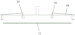
如图3所示,所述转运夹具34上设有真空吸盘35或者电磁吸铁,所述真空吸盘35或者电磁吸铁能够吸放吊运所述托板11,定位好,速度快。As shown in FIG. 3 , the
如图4所示,所述凝胶颗粒12存放于所述布料机构4中,所述布料机构4用于在所述型腔模具1中铺设并抹平所述凝胶颗粒12,形成所述凝胶颗粒12层;具体地,所述布料机构4包括料斗滑轨41、料斗42和第一顶升部件,所述料斗滑轨41和所述料斗42滑动配合,所述料斗滑轨41和所述第一顶升部件均连接于所述机架,所述传送导轨2穿过所述料斗滑轨41下方,所述第一顶升部件位于所述传送导轨2处,所述第一顶升部件用于将所述型腔模具1升降,所述料斗42存放所述凝胶颗粒12,所述料斗42沿所述料斗滑轨41移动时,将所述凝胶颗粒12布置于所述型腔模具1中,所述料斗42沿所述料斗滑轨41移动过程中,所述料斗42中所述凝胶颗粒12在自重作用下落入所述型腔模具1,单位时间内所述料斗42出料量基本恒定,通过所述第一顶升部件调节所述型腔模具1内腔相对于所述料斗42底部的高度大小,以此配合所述料斗42移动速度大小,能够控制落入所述型腔模具1中形成所述凝胶颗粒12层的厚度,所述料斗42的布料宽度等于所述型腔模具1内腔宽度,一次完成布料;或者所述料斗42的布料宽度小于所述型腔模具1内腔宽度,往复几次完成布料。As shown in Figure 4, the
如图5所示,所述料斗42底部设有下压角44,所述下压角44将布料后的所述凝胶颗粒12层抹平,所述料斗42沿所述料斗滑轨41运动方向的两侧分别设有所述下压角44,由于所述料斗42下方的所述下压角44在所述料斗42移动过程中形成向下的压力,在由所述下压角44倾斜铺设的所述凝胶颗粒12,使得所述凝胶颗粒12层铺设平整光滑,解决了现有技术布料表面呈波浪状的问题,为保证出料后成型表面的光滑平整,所述料斗42的尾部呈弧形,所述料斗42沿所述料斗滑轨41运动方向的两侧分别设有挡料板43,两个所述挡料板43之间用于所述型腔模具1通过,所述挡料板43适配于所述料斗42底部出料口,将所述凝胶颗粒12封闭于所述料斗42中。As shown in Figure 5, the bottom of the
如图6所示,所述凝胶颗粒12层表面布置加固网13,所述压入机构5用于将所述加固网13压入所述凝胶颗粒12层厚度方向的中间位置;具体地,所述压入机构5包括安装座、第二升降缸51、第一导柱53、梳形压板54、刮砂板55和深度调节部件56,所述机架上设置所述第一导柱53,所述第一导柱53连接所述安装座,所述安装座上设置所述第二升降缸51,所述第二升降缸51连接所述梳形压板54,所述梳形压板54滑动连接于所述第一导柱53,所述传送导轨2穿过所述梳形压板54下方,所述梳形压板54包括母板和若干条板541,所述条板541竖向设置,且其顶端连接于所述母板底部,所述条板541的底端齐平,相邻所述条板541之间间隔设置,如图8所示,所述梳形压板54将所述加固网13压入所述凝胶颗粒12层中,所述第二升降缸51带动所述梳形压板54升降,所述梳形压板54通过所述第一导柱53导向,确保所述梳形压板54移动路径的准确性,若干所述条板541底端抵接在所述加固网13上将其压入所述凝胶颗粒层12,所述条板541底端作用面积小,压强大,压入效果好,还能最大程度减小对所述凝胶颗粒层12的破坏,以便后续对所述凝胶颗粒层12压实,所述第一导柱53包括至少三个,设置在所述梳形压板54周缘;所述刮砂板55通过所述深度调节部件56连接于所述机架,所述刮砂板55滑动连接于所述第一导柱53,所述刮砂板55位于所述梳形压板54和所述传送导轨2之间,如图7所示,所述刮砂板55上设有若干与所述条板541一一对应的通孔,所述条板541能够穿过所述通孔后抵接所述加固网13,所述深度调节部件56调节所述刮砂板55的高度,以调节所述梳形压板54将所述加固网13压入所述凝胶颗粒12层中的位置,采用这种结构,所述条板541在插入所述凝胶颗粒12层后易粘附有所述凝胶颗粒12,如图9所示,在所述第二升降缸51提升所述梳形压板54时,所述刮砂板55将所述条板541粘附的所述凝胶颗粒12清理干净,所述深度调节部件56能够根据需要制作的板厚来限制所述梳形压板54下压至合适的位置,所述第一导柱53确保所述条板541准确进入所述通孔;所述梳形压板54上设有第二振动电机52,在所述加固网13下压过程中使所述梳形压板54上下振动,能够保证所述加固网13得到良好的压入效果,对于胶凝剂粘附效果较好的所述凝胶颗粒12,还能够通过振动减少所述凝胶颗粒12粘附于所述条板541上,所述第二振动电机52包括偶数个且成对布置,每一对所述第二振动电机52的摆轮转动方向相反。As shown in Figure 6, a reinforcing net 13 is arranged on the surface of the gel particle 12 layer, and the pressing mechanism 5 is used to press the reinforcing net 13 into the middle position in the thickness direction of the gel particle 12 layer; specifically , the press-in mechanism 5 includes a mounting seat, a second lifting cylinder 51, a first guide post 53, a comb-shaped pressing plate 54, a sand scraper 55 and a depth adjustment component 56, and the first guide post is arranged on the frame 53, the first guide post 53 is connected to the mounting seat, the second lifting cylinder 51 is arranged on the mounting seat, the second lifting cylinder 51 is connected to the comb-shaped pressing plate 54, and the comb-shaped pressing plate 54 Slidingly connected to the first guide post 53, the transmission guide rail 2 passes under the comb-shaped pressing plate 54, the comb-shaped pressing plate 54 includes a motherboard and several strips 541, the strips 541 are vertically arranged, And its top is connected to the bottom of the mother board, the bottom ends of the strips 541 are flush, and the adjacent strips 541 are arranged at intervals, as shown in Figure 8, the comb-shaped pressing plate 54 reinforces the The net 13 is pressed into the layer of gel particles 12, the second lifting cylinder 51 drives the comb-shaped pressing plate 54 to lift, and the comb-shaped pressing plate 54 is guided by the first guide post 53 to ensure that the comb-shaped The accuracy of the moving path of the pressing plate 54, the bottom ends of several strips 541 abut against the reinforcement net 13 to press them into the gel particle layer 12, the bottoms of the strips 541 have a small action area and a strong pressure , the pressing effect is good, and the damage to the gel particle layer 12 can also be minimized, so that the subsequent compaction of the gel particle layer 12, the first guide post 53 includes at least three, arranged at The peripheral edge of the comb-shaped pressing plate 54; the sand scraping plate 55 is connected to the frame through the depth adjustment member 56, and the sand scraping plate 55 is slidably connected to the first guide post 53, and the sand scraping plate 55 is located between the comb-shaped pressing plate 54 and the conveying guide rail 2, as shown in Figure 7, the sand scraping plate 55 is provided with a number of through holes corresponding to the strips 541 one by one, and the strips 541 can pass through the through hole and abut against the reinforcing net 13, the depth adjustment part 56 adjusts the height of the scraping plate 55 to adjust the comb-shaped pressing plate 54 to press the reinforcing net 13 into the The position in the 12 layers of gel particles, with this structure, the strip 541 is easy to adhere to the gel particles 12 after being inserted into the 12 layers of gel particles, as shown in Figure 9, in the When the second lifting cylinder 51 lifts the comb-shaped pressing plate 54, the scraping plate 55 will clean up the gel particles 12 adhered to the strip 541, and the depth adjusting part 56 can be made according to the needs. thick to limit the pressing of the comb-shaped
如图10所示,所述振动成型机构6用于对所述型腔模具1中的所述凝胶颗粒12层振压到需求厚度,微粒板材成型;具体地,所述振动成型机构6包括安装板、第三升降缸61、第一振动电机62、第二导柱63、振动压板64、深度限位部件65和第二顶升部件,所述机架上设置所述第二导柱63,所述第二导柱63连接所述安装板,所述安装板上设置所述第三升降缸61,所述第三升降缸61连接所述振动压板64,所述振动压板64滑动连接于所述第二导柱63,所述第二导柱63包括至少三个,设置在所述振动压板64周缘,所述振动压板64上设置所述第一振动电机62,所述传送导轨2穿过所述振动压板64下方,所述振动压板64的纵截面为T型,所述振动压板64底面大小适配所述型腔模具1内腔大小,所述振动压板64一边振动一边下压所述凝胶颗粒12层到需求厚度,采用这种结构,所述第一振动电机62带动所述振动压板64振动,所述第三升降缸61带动所述振动压板64升降,所述第二导柱63确保所述振动压板64准确进入所述型腔模具1内腔,防止所述振动压板64产生偏移不能合模;所述第一振动电机62包括偶数个且成对布置,每一对所述第一振动电机62的摆轮转动方向相反;所述深度限位部件65和所述第二顶升部件均连接于所述机架,所述深度限位部件65用于限制所述振动压板64下压高度,以调节所述凝胶颗粒12层的厚度,所述第二顶升部件位于所述传送导轨2处,所述第二顶升部件用于将所述托板11及其承载的所述微粒板材从所述型腔模具1顶升脱模。As shown in Figure 10, the
如图11所示,在所述凝胶颗粒12层表面放置防粘膜14,防止微粒板材成型后与所述振动压板64粘连,所述振动压板64缓慢压下,当所述振动压板64与所述凝胶颗粒12层表面接触后开启振动,下压到需求厚度时停止,提升所述振动压板64,取下所述防粘膜14,微粒板材成型。As shown in Figure 11, an
如图1所示,所述传送导轨2依次传输所述型腔模具1至所述布料机构4、所述压入机构5和所述振动成型机构6;所述第一滑动导轨7设于所述传送导轨2前端,所述托板转运机构3用于将所述第一滑动导轨7传输的所述托板11安装到所述型腔模具1中,所述滑块滑轨31一部分位于所述传送导轨2上方,另一部分位于所述第一滑动导轨7上方;所述第二滑动导轨8设于所述传送导轨2后端,所述第二滑动导轨8用于传输脱模后的所述托板11及其承载的所述微粒板材;采用这种结构,所述型腔模具1专注于所述凝胶颗粒12成型,在所述传送导轨2上流转,所述托板11用于所述微粒板材的转运,所述第一滑动导轨7和所述第二滑动导轨8用于所述托板11的流水倒运,使得整个所述微粒板材的生产流水化作业,提升了生产效率。As shown in Figure 1, the
本发明所述的一种微粒板材成型装置,通过所述型腔模具1成型微粒材料板材,产品的尺寸、形位误差得到明显改善提升,通过所述布料机构4与所述型腔模具1的配合可调节布置于所述型腔模具1内的所述凝胶颗粒12量,保证微粒产品制作的材料用量,批次产品重量均衡、一致性好,所述布料机构4布料的同时能够抹平所述凝胶颗粒12表面;通过所述振动成型机构6对所述凝胶颗粒12振压成型,能充分的对微粒材料均匀的下压,保证产品的密实度,产品质量高;所述凝胶颗粒12一次布料于所述型腔模具1内,减少了所述凝胶颗粒12布置次数,所述加固网13直接压入所述凝胶颗粒12层中,减化了微粒材料的生产动作,提高了生产效率;在成型后即将所述托板11和微粒产品从所述型腔模具1中取出,减少了所述型腔模具1的投入数量,方便所述型腔模具1运转,快速流水作业,以便产业化;该装置使用简单,操作方便,效果良好。In the particle sheet molding device of the present invention, the particle material sheet is formed by the cavity mold 1, the size and shape error of the product are significantly improved, and the distribution mechanism 4 and the cavity mold 1 are connected Cooperate with the amount of the gel particles 12 that can be adjusted and arranged in the cavity mold 1 to ensure the amount of materials used in the production of particulate products, the weight of batches of products is balanced, and the consistency is good, and the cloth distribution mechanism 4 can smooth the cloth while The surface of the gel particle 12; through the vibration molding mechanism 6, the gel particle 12 can be vibrated and formed, which can fully and evenly press down on the particulate material to ensure the compactness of the product and high product quality; The glue particles 12 are placed in the cavity mold 1 at one time, reducing the number of times the gel particles 12 are arranged, and the reinforcement mesh 13 is directly pressed into the layer of the gel particles 12, which reduces the production action of the particulate material , improve production efficiency; be about to take out described pallet 11 and particle product from described cavity mold 1 after forming, reduce the input quantity of described cavity mold 1, facilitate described cavity mold 1 to run, fast Assembly line operation is convenient for industrialization; the device is simple to use, easy to operate, and has good effect.
以上所述仅为本发明的较佳实施例而已,并不用以限制本发明,凡在本发明的精神和原则之内所作的任何修改、等同替换和改进等,均应包含在本发明的保护范围之内。The above descriptions are only preferred embodiments of the present invention, and are not intended to limit the present invention. Any modifications, equivalent replacements and improvements made within the spirit and principles of the present invention should be included in the protection of the present invention. within range.
Claims (9)
Priority Applications (1)
| Application Number | Priority Date | Filing Date | Title |
|---|---|---|---|
| CN202110635923.4A CN113478715B (en) | 2021-06-08 | 2021-06-08 | Particle board forming device |
Applications Claiming Priority (1)
| Application Number | Priority Date | Filing Date | Title |
|---|---|---|---|
| CN202110635923.4A CN113478715B (en) | 2021-06-08 | 2021-06-08 | Particle board forming device |
Publications (2)
| Publication Number | Publication Date |
|---|---|
| CN113478715A CN113478715A (en) | 2021-10-08 |
| CN113478715B true CN113478715B (en) | 2023-05-16 |
Family
ID=77934769
Family Applications (1)
| Application Number | Title | Priority Date | Filing Date |
|---|---|---|---|
| CN202110635923.4A Active CN113478715B (en) | 2021-06-08 | 2021-06-08 | Particle board forming device |
Country Status (1)
| Country | Link |
|---|---|
| CN (1) | CN113478715B (en) |
Families Citing this family (3)
| Publication number | Priority date | Publication date | Assignee | Title |
|---|---|---|---|---|
| CN116810971B (en) * | 2023-07-11 | 2024-04-16 | 山东东来市政园林工程有限公司 | Granite plate manufacturing device and manufacturing method |
| CN116728673B (en) * | 2023-07-31 | 2025-09-23 | 中车贵阳车辆有限公司 | A wood particle reinforced composite floor pressing circulation line |
| CN117183071A (en) * | 2023-08-17 | 2023-12-08 | 先导薄膜材料(安徽)有限公司 | An automatic cloth molding mechanism |
Family Cites Families (6)
| Publication number | Priority date | Publication date | Assignee | Title |
|---|---|---|---|---|
| US7497978B2 (en) * | 2003-07-01 | 2009-03-03 | Dzs, Llc. | Process for abrasion-resistant needle-punched composite |
| CN1718402A (en) * | 2005-06-24 | 2006-01-11 | 虎牌机械(天津)有限公司 | Distributing shaping device of colour sandwiched concrete building block production equipment |
| CN202449594U (en) * | 2012-02-13 | 2012-09-26 | 朱培池 | Funnel |
| KR101843735B1 (en) * | 2017-09-28 | 2018-03-30 | 강병조 | A press mold |
| CN110181678B (en) * | 2019-05-28 | 2024-05-31 | 北京凯盛建材工程有限公司 | Composite insulation wall panel production system based on rotary discharge valve |
| CN112248337A (en) * | 2020-09-08 | 2021-01-22 | 刘冬 | Insulation material pre-compaction device for insulation board production line |
-
2021
- 2021-06-08 CN CN202110635923.4A patent/CN113478715B/en active Active
Also Published As
| Publication number | Publication date |
|---|---|
| CN113478715A (en) | 2021-10-08 |
Similar Documents
| Publication | Publication Date | Title |
|---|---|---|
| CN113478715B (en) | Particle board forming device | |
| CN105108962B (en) | Production line and production method for composite heat-insulation decorative board | |
| CN205009474U (en) | Decorative composite insulating panel production line | |
| CN107336327B (en) | A kind of process for producing artificial stone | |
| CN108995017A (en) | One kind exempting from supporting plate static pressure block machine | |
| CN104339440B (en) | Panel forming apparatus | |
| CN115122462B (en) | Ceramic vibration grouting forming device and method | |
| CN111070374B (en) | A kind of automatic feeding device and control method of slurry lamination with variable area range | |
| CN103406979B (en) | Panel forming apparatus | |
| CN115284414B (en) | Wallboard processing and forming device for assembled building | |
| CN108160920B (en) | Novel sand mold (core) 3D printing forming method | |
| CN103406978B (en) | Panel forming apparatus and method | |
| CN116352855B (en) | A brick-making device and method for trimming powder edges | |
| CN219466464U (en) | Brick making equipment capable of trimming powder edge | |
| CN215619477U (en) | Comb-shaped pressing plate and press-in mechanism | |
| CN219522513U (en) | Automatic brick machine capable of preventing brick from falling off | |
| CN110834426A (en) | Composite board production equipment | |
| CN207997412U (en) | A kind of hollow brick production mold automated packing device | |
| CN113926987B (en) | Sand box sand filling system and method | |
| CN109849172B (en) | Double-sided plastering device for heat insulation board | |
| CN203427147U (en) | Plate forming device | |
| CN108202389A (en) | A kind of hollow brick production mold automated packing device | |
| CN207954206U (en) | A kind of bilayer clamp dog forcing press | |
| CN120552217B (en) | Board making machine for wall prefabricated member production | |
| CN110920088A (en) | Preparation production line of quartz synthetic stone board |
Legal Events
| Date | Code | Title | Description |
|---|---|---|---|
| PB01 | Publication | ||
| PB01 | Publication | ||
| SE01 | Entry into force of request for substantive examination | ||
| SE01 | Entry into force of request for substantive examination | ||
| GR01 | Patent grant | ||
| GR01 | Patent grant | ||
| PE01 | Entry into force of the registration of the contract for pledge of patent right | ||
| PE01 | Entry into force of the registration of the contract for pledge of patent right |
Denomination of invention: A microplate forming device Effective date of registration: 20231013 Granted publication date: 20230516 Pledgee: Bank of China Limited Chengdu Wuhou sub branch Pledgor: ZHENG SHENG ENVIRONMENTAL TECHNOLOGY Co.,Ltd. Registration number: Y2023510000229 |
|
| PC01 | Cancellation of the registration of the contract for pledge of patent right | ||
| PC01 | Cancellation of the registration of the contract for pledge of patent right |
Granted publication date: 20230516 Pledgee: Bank of China Limited Chengdu Wuhou sub branch Pledgor: ZHENG SHENG ENVIRONMENTAL TECHNOLOGY Co.,Ltd. Registration number: Y2023510000229 |
|
| PE01 | Entry into force of the registration of the contract for pledge of patent right | ||
| PE01 | Entry into force of the registration of the contract for pledge of patent right |
Denomination of invention: A microplate forming device Granted publication date: 20230516 Pledgee: Bank of China Limited Chengdu Wuhou sub branch Pledgor: ZHENG SHENG ENVIRONMENTAL TECHNOLOGY Co.,Ltd. Registration number: Y2025510000181 |