CN113425237B - Indoor medical equipment capable of being automatically adjusted according to luminous environment - Google Patents
Indoor medical equipment capable of being automatically adjusted according to luminous environment Download PDFInfo
- Publication number
- CN113425237B CN113425237B CN202110576332.4A CN202110576332A CN113425237B CN 113425237 B CN113425237 B CN 113425237B CN 202110576332 A CN202110576332 A CN 202110576332A CN 113425237 B CN113425237 B CN 113425237B
- Authority
- CN
- China
- Prior art keywords
- transmission
- observation
- diameter
- expansion
- bevel gear
- Prior art date
- Legal status (The legal status is an assumption and is not a legal conclusion. Google has not performed a legal analysis and makes no representation as to the accuracy of the status listed.)
- Expired - Fee Related
Links
- 230000007246 mechanism Effects 0.000 claims abstract description 73
- 230000005540 biological transmission Effects 0.000 claims abstract description 62
- 238000013461 design Methods 0.000 claims abstract description 7
- 230000002093 peripheral effect Effects 0.000 claims description 17
- 210000000744 eyelid Anatomy 0.000 abstract description 6
- 238000000034 method Methods 0.000 abstract description 4
- 230000006378 damage Effects 0.000 abstract description 2
- 238000011282 treatment Methods 0.000 description 5
- 238000003745 diagnosis Methods 0.000 description 4
- 210000004279 orbit Anatomy 0.000 description 3
- 238000010586 diagram Methods 0.000 description 2
- 230000000694 effects Effects 0.000 description 2
- 239000000463 material Substances 0.000 description 2
- 238000012986 modification Methods 0.000 description 2
- 230000004048 modification Effects 0.000 description 2
- 238000012544 monitoring process Methods 0.000 description 2
- 238000011160 research Methods 0.000 description 2
- 208000027418 Wounds and injury Diseases 0.000 description 1
- 230000009286 beneficial effect Effects 0.000 description 1
- 201000010099 disease Diseases 0.000 description 1
- 208000037265 diseases, disorders, signs and symptoms Diseases 0.000 description 1
- 239000000428 dust Substances 0.000 description 1
- 210000003128 head Anatomy 0.000 description 1
- 208000014674 injury Diseases 0.000 description 1
- 230000004060 metabolic process Effects 0.000 description 1
- 230000000116 mitigating effect Effects 0.000 description 1
- 230000035790 physiological processes and functions Effects 0.000 description 1
- 230000035935 pregnancy Effects 0.000 description 1
- 230000002265 prevention Effects 0.000 description 1
- 238000006467 substitution reaction Methods 0.000 description 1
Images


Classifications
-
- A—HUMAN NECESSITIES
- A61—MEDICAL OR VETERINARY SCIENCE; HYGIENE
- A61B—DIAGNOSIS; SURGERY; IDENTIFICATION
- A61B3/00—Apparatus for testing the eyes; Instruments for examining the eyes
- A61B3/0083—Apparatus for testing the eyes; Instruments for examining the eyes provided with means for patient positioning
-
- A—HUMAN NECESSITIES
- A61—MEDICAL OR VETERINARY SCIENCE; HYGIENE
- A61B—DIAGNOSIS; SURGERY; IDENTIFICATION
- A61B3/00—Apparatus for testing the eyes; Instruments for examining the eyes
- A61B3/10—Objective types, i.e. instruments for examining the eyes independent of the patients' perceptions or reactions
-
- Y—GENERAL TAGGING OF NEW TECHNOLOGICAL DEVELOPMENTS; GENERAL TAGGING OF CROSS-SECTIONAL TECHNOLOGIES SPANNING OVER SEVERAL SECTIONS OF THE IPC; TECHNICAL SUBJECTS COVERED BY FORMER USPC CROSS-REFERENCE ART COLLECTIONS [XRACs] AND DIGESTS
- Y02—TECHNOLOGIES OR APPLICATIONS FOR MITIGATION OR ADAPTATION AGAINST CLIMATE CHANGE
- Y02B—CLIMATE CHANGE MITIGATION TECHNOLOGIES RELATED TO BUILDINGS, e.g. HOUSING, HOUSE APPLIANCES OR RELATED END-USER APPLICATIONS
- Y02B20/00—Energy efficient lighting technologies, e.g. halogen lamps or gas discharge lamps
- Y02B20/40—Control techniques providing energy savings, e.g. smart controller or presence detection
Landscapes
- Life Sciences & Earth Sciences (AREA)
- Health & Medical Sciences (AREA)
- Medical Informatics (AREA)
- Biophysics (AREA)
- Ophthalmology & Optometry (AREA)
- Engineering & Computer Science (AREA)
- Biomedical Technology (AREA)
- Heart & Thoracic Surgery (AREA)
- Physics & Mathematics (AREA)
- Molecular Biology (AREA)
- Surgery (AREA)
- Animal Behavior & Ethology (AREA)
- General Health & Medical Sciences (AREA)
- Public Health (AREA)
- Veterinary Medicine (AREA)
- Non-Portable Lighting Devices Or Systems Thereof (AREA)
- Surgical Instruments (AREA)
Abstract
本发明提供一种可依据光环境自动调节的室内医疗设备,涉及医疗设备技术领域,解决了现有的眼部照明设备在实际应用过程中存在着一是因无法根据室内光环境进行对眼部照射的进光量进行自动调节,因此会因无法随环境而调节光照强度造成患者的眼部产生不适,再者是无法在医生进行多角度观察患者眼部的同时对患者的眼部进行观察部位的撑开操作,进而存在着使用不便的问题,包括传动机构,所述传动机构共设有两处,本发明中,可通过锥齿轮组将横向的动力转化为竖向并通过传动轴与扩张板之间的啮合传动驱动扩张板通过吸盘将患者的眼皮进行反向撑开,进而更加方便观察,该设计通过吸盘代替传动的眼皮拨动装置多为拨杆会对眼皮及眼部造成伤害的情况出现。
The invention provides an indoor medical device that can be automatically adjusted according to the light environment, relates to the technical field of medical devices, and solves the problem of the existing eye lighting device in the actual application process. The amount of incoming light is automatically adjusted, so the patient’s eyes will be uncomfortable because the light intensity cannot be adjusted according to the environment, and it is impossible to observe the patient’s eyes while the doctor observes the patient’s eyes from multiple angles. The opening operation further has the problem of inconvenience in use, including the transmission mechanism, which is provided with two places. In the present invention, the horizontal power can be converted into the vertical through the bevel gear set and passed through the transmission shaft and the expansion plate. The meshing transmission drives the expansion plate to open the patient's eyelids in the reverse direction through the suction cup, which is more convenient for observation. This design uses the suction cup to replace the transmission of the eyelid toggle device mostly because the toggle lever will cause damage to the eyelids and eyes. Appear.
Description
技术领域technical field
本发明属于医疗设备技术领域,更具体地说,特别涉及一种可依据光环境自动调节的室内医疗设备。The invention belongs to the technical field of medical equipment, and more particularly, particularly relates to an indoor medical equipment that can be automatically adjusted according to the light environment.
背景技术Background technique
医疗设备是指单独或者组合使用于人体的仪器、设备、器具、材料或者其他物品,也包括所需要的软件,医疗设备是医疗、科研、教学、机构、临床学科工作最基本要素,即包括专业医疗设备,也包括家用医疗设备,医疗设备是指单独或者组合使用于人体的仪器、设备、器具、材料或者其他物品,也包括所需要的软件,对于人体体表及体内的治疗效果不是通过药理学、免疫学或者代谢的手段来获得,而是医疗器械产品起到了一定的辅助作用,在使用期间,旨在达到下列预期目的:对疾病的预防、诊断、治疗、监护、缓解;对损伤或者残疾的诊断、治疗、监护、缓解、补偿;对解剖或者生理过程的研究、替代、调节;妊娠控制,医生在针对于患者的眼部进行诊疗时需先对患者的眼部进行有效的观察工作,进而可实现高效的诊疗工作。Medical equipment refers to the instruments, equipment, appliances, materials or other items used in the human body alone or in combination, and also includes the required software. Medical equipment is the most basic element of medical treatment, scientific research, teaching, institutions, and clinical disciplines. Medical equipment, also includes household medical equipment, medical equipment refers to the instruments, equipment, appliances, materials or other items that are used in the human body alone or in combination, and also includes the required software. It is obtained by means of science, immunology or metabolism, but medical device products play a certain auxiliary role. During use, it aims to achieve the following intended purposes: prevention, diagnosis, treatment, monitoring, and mitigation of diseases; Diagnosis, treatment, monitoring, relief, and compensation of disability; research, substitution, and adjustment of anatomical or physiological processes; pregnancy control. Doctors need to conduct effective observation of the patient's eyes before diagnosis and treatment of the patient's eyes. , so as to achieve efficient diagnosis and treatment.
例如申请号:CN201911324724.0,本发明涉及医疗器具技术领域,具体是一种眼科用眼部观察灯,包括底座,所述底座的下侧左右对称的设置有支撑装置,底座的上侧开设有放置腔,所述放置腔的上端设置有盖板,所述放置腔的内部设置有旋转座,所述旋转座上旋转安装有伸缩杆,所述伸缩杆的外端设置有灯体,所述盖板与伸缩杆的支撑部连接,盖板的外侧设置有把手,盖板与底座之间设置有锁定机构,放置腔的内部开设有凹槽,凹槽的内部设置有柔性垫,灯体与凹槽配合设置。本装置的结构设置,伸缩杆与盖板连接,在不使用时,可以进行折叠,降低了装置的体积,使得装置便于存放和运输,并且可以对灯体进行保护,防止灯体受到外部灰尘的影响,保证使用的效果。For example, application number: CN201911324724.0, the present invention relates to the technical field of medical devices, in particular to an eye observation lamp for ophthalmology, comprising a base, the lower side of the base is provided with a support device symmetrically, and the upper side of the base is provided with A placement cavity, the upper end of the placement cavity is provided with a cover plate, the interior of the placement cavity is provided with a rotating seat, a telescopic rod is rotatably installed on the rotating seat, and the outer end of the telescopic rod is provided with a lamp body, the The cover plate is connected with the support part of the telescopic rod, a handle is arranged on the outside of the cover plate, a locking mechanism is arranged between the cover plate and the base, a groove is opened in the inside of the placement cavity, and a flexible pad is arranged inside the groove, and the lamp body is connected to the base. Groove fit settings. The structure of the device is arranged, the telescopic rod is connected with the cover plate, and can be folded when not in use, which reduces the volume of the device, makes the device easy to store and transport, and can protect the lamp body from external dust. influence, to ensure the effect of use.
基于上述专利的检索,以及结合现有技术中的设备发现,上述设备在应用时,虽然可以进行对眼部的照明工作,但在实际应用过程中存在着一是因无法根据室内光环境进行对眼部照射的进光量进行自动调节,因此会因无法随环境而调节光照强度造成患者的眼部产生不适,再者是无法在医生进行多角度观察患者眼部的同时对患者的眼部进行观察部位的撑开操作,进而存在着使用不便。Based on the retrieval of the above-mentioned patents and combined with the equipment in the prior art, although the above-mentioned equipment can illuminate the eyes during application, there is one problem in the actual application process because it cannot be adjusted according to the indoor light environment. The amount of light entering the eyes is automatically adjusted, so the patient's eyes will be uncomfortable due to the inability to adjust the light intensity according to the environment, and it is impossible to observe the patient's eyes while the doctor observes the patient's eyes from multiple angles. The opening operation of the part is inconvenient to use.
发明内容SUMMARY OF THE INVENTION
为了解决上述技术问题,本发明提供一种可依据光环境自动调节的室内医疗设备,以解决现有的眼部照明设备在实际应用过程中存在着一是因无法根据室内光环境进行对眼部照射的进光量进行自动调节,因此会因无法随环境而调节光照强度造成患者的眼部产生不适,再者是无法在医生进行多角度观察患者眼部的同时对患者的眼部进行观察部位的撑开操作,进而存在着使用不便的问题。In order to solve the above technical problems, the present invention provides an indoor medical device that can be automatically adjusted according to the light environment, so as to solve the problem of existing eye lighting equipment in the actual application process. The amount of incoming light to be irradiated is automatically adjusted, so the inability to adjust the light intensity with the environment will cause discomfort to the patient's eyes, and it is impossible for the doctor to observe the patient's eyes from multiple angles while observing the patient's eyes. The opening operation has a problem of inconvenience in use.
本发明一种可依据光环境自动调节的室内医疗设备的目的与功效,由以下具体技术手段所达成:The purpose and effect of an indoor medical device that can be automatically adjusted according to the light environment of the present invention is achieved by the following specific technical means:
一种可依据光环境自动调节的室内医疗设备,包括传动机构、观察机构和扩张机构,所述传动机构共设有两处,且两处传动机构分别安装在调节机构的内部前端上下两侧位置;所述观察机构插接在调节机构的内部位置;所述扩张机构共设有两处,且两处扩张机构分别传动连接在两处传动机构的内侧位置;所述扩张机构还包括有扩张板和吸盘,所述扩张板为弧形结构设计,扩张板的弧度与观察器的底端弧度一致,且扩张板的左右两侧面对称安装有两处导板,并且两处导板的内侧均开设有圆孔,其中与传动轴相接触的圆孔内壁开设有与传动轴外周面上所开设的螺纹相匹配的螺纹。An indoor medical device that can be automatically adjusted according to the light environment, including a transmission mechanism, an observation mechanism and an expansion mechanism. There are two transmission mechanisms in total, and the two transmission mechanisms are respectively installed at the upper and lower sides of the inner front end of the adjustment mechanism. ; the observation mechanism is inserted into the internal position of the adjustment mechanism; the expansion mechanism is provided with two places, and the two expansion mechanisms are respectively connected to the inner positions of the two transmission mechanisms; the expansion mechanism also includes an expansion plate and suction cup, the expansion plate is of arc structure design, the radian of the expansion plate is consistent with the radian of the bottom end of the observer, and two guide plates are installed symmetrically on the left and right sides of the expansion plate, and the inner sides of the two guide plates are provided with circles. A hole, wherein the inner wall of the circular hole in contact with the transmission shaft is provided with threads that match the threads opened on the outer peripheral surface of the transmission shaft.
进一步的,所述调节机构包括有观察罩和承载管,所述观察罩为前宽后窄的斗形结构设计,且观察罩的前端开口为长方形,后端开口为圆形,并且观察罩的内部后侧内壁上开设有螺纹,所述承载管截面为长方体结构设计,且承载管的前端安装有螺头,螺头的外周面上所开设的螺纹与观察罩内壁所开设的螺纹相匹配,并且承载管的长度大于观察罩的长度,承载管的方形管顶端开设有方形孔;Further, the adjustment mechanism includes an observation hood and a carrying tube, the observation hood is a bucket-shaped structure with a wide front and a narrow rear, and the front opening of the observation hood is rectangular, the rear opening is circular, and the observation hood has a The inner wall of the rear side is provided with threads, the cross-section of the bearing tube is designed in a cuboid structure, and the front end of the bearing tube is installed with a screw head, and the screw thread opened on the outer peripheral surface of the screw head matches the thread opened on the inner wall of the observation cover. And the length of the carrying tube is greater than the length of the observation cover, and the top of the square tube of the carrying tube is provided with a square hole;
进一步的,所述调节机构还包括有光感器、驱动器和遮板,所述光感器安装在承载管的上方,且光感器与铰接在承载管的方形管顶端的驱动器电性相连接,并且驱动器还与遮板相铰接,所述遮板与承载管处于平行状态时大小与承载管顶端所开设的方形孔相匹配;Further, the adjustment mechanism also includes a light sensor, a driver and a shutter, the light sensor is installed above the carrier tube, and the light sensor is electrically connected to the driver hinged on the top of the square tube of the carrier tube. , and the driver is also hinged with the shutter, and the size of the shutter and the bearing tube when they are in a parallel state matches the square hole opened at the top of the bearing tube;
进一步的,所述传动机构包括有定位套、齿条和驱动齿轮,所述定位套为环形结构设计,且定位套的内部所开设的圆孔的直径与观察器的外周面最大处直径一致,所述齿条共设有两处,且两处齿条分别垂直安装在定位套的外周面顶侧及底侧位置,并且两处齿条的后侧均啮合传动有驱动齿轮,驱动齿轮的宽度大于齿条的宽度,且每处驱动齿轮通过限位板转动连接在两处限位板的内侧位置;Further, the transmission mechanism includes a positioning sleeve, a rack and a drive gear, the positioning sleeve is designed in an annular structure, and the diameter of the circular hole opened in the positioning sleeve is consistent with the diameter of the largest part of the outer peripheral surface of the observer, There are two racks in total, and the two racks are installed vertically on the top side and bottom side of the outer peripheral surface of the positioning sleeve, and the rear sides of the two racks are meshed with driving gears. The width of the driving gear Greater than the width of the rack, and each drive gear is connected to the inner position of the two limit plates through the limit plate rotation;
进一步的,所述传动机构还包括有从动齿轮和链条,所述从动齿轮的直径与驱动齿轮的直径一致,但从动齿轮的宽度小于驱动齿轮的宽度,并且两处从动齿轮之间通过链条相啮合传动,两处从动齿轮及链条构成了传动机构和扩张机构之间的传动结构;Further, the transmission mechanism also includes a driven gear and a chain, the diameter of the driven gear is the same as the diameter of the driving gear, but the width of the driven gear is smaller than the width of the driving gear, and there is a gap between the two driven gears. Through the meshing transmission of the chain, the two driven gears and the chain constitute the transmission structure between the transmission mechanism and the expansion mechanism;
进一步的,所述观察机构包括有观察器,所述观察器为一圆柱形加一锥台结构设计,且两处观察器为对向安装,并在两处观察器的内侧安装有连接管,而连接管的直径与两处观察器内部锥台结构的最小直径侧的直径大小一致,且连接管与两处观察器相贯通连接;Further, the observation mechanism includes an observer, the observer is a cylindrical and a truncated cone structure design, and the two observers are installed oppositely, and a connecting pipe is installed on the inner side of the two observers, The diameter of the connecting pipe is the same as the diameter of the smallest diameter side of the inner frustum structure of the two observers, and the connecting pipe is connected to the two observers;
进一步的,所述观察机构还包括有调距钮和透镜,所述调距钮安装在两处观察器内侧所安装在连接管的外周面顶侧位置,所述透镜共设有两处,且两处透镜分别安装在两处观察器的外侧位置,并且两处透镜均可通过调距钮进行调距;Further, the observation mechanism also includes a distance adjustment button and a lens, the distance adjustment button is installed on the inside of the observer at two positions on the top side of the outer peripheral surface of the connecting pipe, and the lens is provided at two places in total, and The two lenses are installed at the outer positions of the two observers, and the distance of the two lenses can be adjusted by the distance adjustment knob;
进一步,所述扩张机构包括有锥齿轮组和传动轴,所述锥齿轮组的直径小于从动齿轮的直径,且两处锥齿轮组分别安装在两处从动齿轮的前后两侧位置,并且两处锥齿轮组均可将两处横向传动力的从动齿轮的力转化为相互平行的纵向力的传动,所述传动轴共设有两处,且两处传动轴分别安装在两处锥齿轮组的内侧位置,并且两处传动轴相互平行,并均与锥齿轮组相垂直。Further, the expansion mechanism includes a bevel gear set and a transmission shaft, the diameter of the bevel gear set is smaller than the diameter of the driven gear, and the two bevel gear sets are respectively installed on the front and rear sides of the two driven gears, and The two bevel gear sets can convert the force of the driven gear of the two lateral transmission forces into the transmission of the longitudinal force parallel to each other. There are two transmission shafts, and the two transmission shafts are respectively installed on the two cones The inner position of the gear set, and the two transmission shafts are parallel to each other and are both perpendicular to the bevel gear set.
与现有技术相比,本发明具有如下有益效果:Compared with the prior art, the present invention has the following beneficial effects:
本发明中,由于调节机构中的观察罩为前宽后窄的斗形结构设计,且观察罩的前端开口为长方形,后端开口为圆形,并且观察罩的内部后侧内壁上开设有螺纹,承载管截面为长方体结构设计,因此在当医生将眼部放置在安装在观察罩内侧的观察器内部进行观察,并可通过调距钮进行实时调整缩放倍数以便于观察,再者是可通过光感器对室内的光环境进行监测,当光照强度过高时可通过驱动器将遮板对承载管上的方形开孔进行遮蔽,以达到更加实用的目的。In the present invention, because the observation cover in the adjustment mechanism is a bucket-shaped structure with a wide front and a narrow back, the front opening of the observation cover is rectangular, the rear opening is circular, and the inner wall of the observation cover is provided with threads on the inner rear side. , The cross section of the carrying tube is designed as a cuboid structure, so when the doctor places the eye in the observer installed on the inside of the observation hood for observation, the zoom factor can be adjusted in real time through the distance adjustment button to facilitate observation. The light sensor monitors the light environment in the room, and when the light intensity is too high, the shutter can be used to shield the square opening on the carrier tube through the driver, so as to achieve a more practical purpose.
另一方面,由于两处齿条的后侧均啮合传动有驱动齿轮,因此在当使用者通过眼眶带动观察器进行上下运动时,会通过锥齿轮组将横向的动力转化为竖向并通过传动轴与扩张板之间的啮合传动驱动扩张板通过吸盘将患者的眼皮进行反向撑开,进而更加方便观察,该设计通过吸盘代替传动的眼皮拨动装置多为拨杆会对眼皮及眼部造成伤害的情况出现。On the other hand, since the rear sides of the two racks are meshed with driving gears, when the user drives the viewer to move up and down through the eye socket, the horizontal power will be converted into the vertical through the bevel gear set and the transmission The meshing transmission between the shaft and the expansion plate drives the expansion plate to open the patient's eyelids in the opposite direction through the suction cup, which is more convenient for observation. In this design, the suction cup replaces the transmission of the eyelid toggle device. Injury occurs.
附图说明Description of drawings
图1是本发明的部分结构半剖状态下的左侧视结构示意图。FIG. 1 is a schematic left side view of a partial structure of the present invention in a half-section state.
图2是本发明的部分结构半剖状态下的仰侧视结构示意图。FIG. 2 is a schematic view of the bottom side view of the partial structure of the present invention in a half-section state.
图3是本发明的部分结构半剖状态下的主视结构示意图。FIG. 3 is a schematic front view of the partial structure of the present invention in a half-section state.
图4是本发明的部分结构半剖状态下的左视结构示意图。FIG. 4 is a left-view structural schematic diagram of a partial structure of the present invention in a half-section state.
图5是本发明的部分结构半剖状态下的右侧视结构示意图。FIG. 5 is a schematic view of the right side view of the partial structure of the present invention in a half-section state.
图6是本发明的图1中A处放大结构示意图。FIG. 6 is an enlarged schematic view of the structure at A in FIG. 1 of the present invention.
图7是本发明的观察机构结构示意图。FIG. 7 is a schematic view of the structure of the observation mechanism of the present invention.
图8是本发明的扩张机构结构示意图。FIG. 8 is a schematic structural diagram of the expansion mechanism of the present invention.
图中,部件名称与附图编号的对应关系为:In the figure, the corresponding relationship between component names and drawing numbers is:
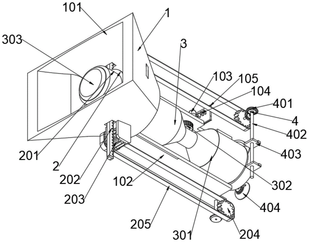
1、调节机构;101、观察罩;102、承载管;103、光感器;104、驱动器;105、遮板;2、传动机构;201、定位套;202、齿条;203、驱动齿轮;204、从动齿轮;205、链条;3、观察机构;301、观察器;302、调距钮;303、透镜;4、扩张机构;401、锥齿轮组;402、传动轴;403、扩张板;404、吸盘。1. Adjustment mechanism; 101, Observation cover; 102, bearing tube; 103, light sensor; 104, driver; 105, shutter; 2, transmission mechanism; 201, positioning sleeve; 202, rack; 203, driving gear; 204, driven gear; 205, chain; 3, observation mechanism; 301, observer; 302, pitch knob; 303, lens; 4, expansion mechanism; 401, bevel gear set; 402, transmission shaft; 403, expansion plate ; 404, sucker.
具体实施方式Detailed ways
下面结合附图和实施例对本发明的实施方式作进一步详细描述。以下实施例用于说明本发明,但不能用来限制本发明的范围。The embodiments of the present invention will be described in further detail below with reference to the accompanying drawings and examples. The following examples are intended to illustrate the present invention, but not to limit the scope of the present invention.
在本发明的描述中,除非另有说明,“多个”的含义是两个或两个以上;术语“上”、“下”、“左”、“右”、“内”、“外”、“前端”、“后端”、“头部”、“尾部”等指示的方位或位置关系为基于附图所示的方位或位置关系,仅是为了便于描述本发明和简化描述,而不是指示或暗示所指的装置或元件必须具有特定的方位、以特定的方位构造和操作,因此不能理解为对本发明的限制。此外,术语“第一”、“第二”、“第三”等仅用于描述目的,而不能理解为指示或暗示相对重要性。In the description of the present invention, unless otherwise stated, "plurality" means two or more; the terms "upper", "lower", "left", "right", "inner", "outer" The orientation or positional relationship indicated by , "front end", "rear end", "head", "tail", etc. are based on the orientation or positional relationship shown in the accompanying drawings, and are only for the convenience of describing the present invention and simplifying the description, not An indication or implication that the referred device or element must have a particular orientation, be constructed and operate in a particular orientation, is not to be construed as a limitation of the invention. Furthermore, the terms "first," "second," "third," etc. are used for descriptive purposes only and should not be construed to indicate or imply relative importance.
在本发明的描述中,需要说明的是,除非另有明确的规定和限定,术语“相连”、“连接”应做广义理解,例如,可以是固定连接,也可以是可拆卸连接,或一体地连接;可以是机械连接,也可以是电连接;可以是直接相连,也可以通过中间媒介间接相连。对于本领域的普通技术人员而言,可以具体情况理解上述术语在本发明中的具体含义。In the description of the present invention, it should be noted that, unless otherwise expressly specified and limited, the terms "connected" and "connected" should be understood in a broad sense, for example, it may be a fixed connection, a detachable connection, or an integral connection. Ground connection; it can be a mechanical connection or an electrical connection; it can be directly connected or indirectly connected through an intermediate medium. For those of ordinary skill in the art, the specific meanings of the above terms in the present invention can be understood in specific situations.
实施例:Example:
如附图1至附图8所示:As shown in accompanying drawings 1 to 8:
本发明提供一种可依据光环境自动调节的室内医疗设备,包括有:传动机构2、观察机构3和扩张机构4,传动机构2共设有两处,且两处传动机构2分别安装在调节机构1的内部前端上下两侧位置;观察机构3插接在调节机构1的内部位置;扩张机构4共设有两处,且两处扩张机构4分别传动连接在两处传动机构2的内侧位置;扩张机构4还包括有扩张板403和吸盘404,扩张板403为弧形结构设计,扩张板403的弧度与观察器301的底端弧度一致,且扩张板403的左右两侧面对称安装有两处导板,并且两处导板的内侧均开设有圆孔,其中与传动轴402相接触的圆孔内壁开设有与传动轴402外周面上所开设的螺纹相匹配的螺纹。The present invention provides an indoor medical device that can be automatically adjusted according to the light environment, including: a
其中,调节机构1包括有观察罩101和承载管102,观察罩101为前宽后窄的斗形结构设计,且观察罩101的前端开口为长方形,后端开口为圆形,并且观察罩101的内部后侧内壁上开设有螺纹,承载管102截面为长方体结构设计,且承载管102的前端安装有螺头,螺头的外周面上所开设的螺纹与观察罩101内壁所开设的螺纹相匹配,并且承载管102的长度大于观察罩101的长度,承载管102的方形管顶端开设有方形孔。The adjustment mechanism 1 includes an
其中,调节机构1还包括有光感器103、驱动器104和遮板105,光感器103安装在承载管102的上方,且光感器103与铰接在承载管102的方形管顶端的驱动器104电性相连接,并且驱动器104还与遮板105相铰接,遮板105与承载管102处于平行状态时大小与承载管102顶端所开设的方形孔相匹配。The adjustment mechanism 1 further includes a
其中,传动机构2包括有定位套201、齿条202和驱动齿轮203,定位套201为环形结构设计,且定位套201的内部所开设的圆孔的直径与观察器301的外周面最大处直径一致,齿条202共设有两处,且两处齿条202分别垂直安装在定位套201的外周面顶侧及底侧位置,并且两处齿条202的后侧均啮合传动有驱动齿轮203,驱动齿轮203的宽度大于齿条202的宽度,且每处驱动齿轮203通过限位板转动连接在两处限位板的内侧位置。The
其中,传动机构2还包括有从动齿轮204和链条205,从动齿轮204的直径与驱动齿轮203的直径一致,但从动齿轮204的宽度小于驱动齿轮203的宽度,并且两处从动齿轮204之间通过链条205相啮合传动,两处从动齿轮204及链条205构成了传动机构2和扩张机构4之间的传动结构。The
其中,观察机构3包括有观察器301,观察器301为一圆柱形加一锥台结构设计,且两处观察器301为对向安装,并在两处观察器301的内侧安装有连接管,而连接管的直径与两处观察器301内部锥台结构的最小直径侧的直径大小一致,且连接管与两处观察器301相贯通连接。Wherein, the
其中,观察机构3还包括有调距钮302和透镜303,调距钮302安装在两处观察器301内侧所安装在连接管的外周面顶侧位置,透镜303共设有两处,且两处透镜303分别安装在两处观察器301的外侧位置,并且两处透镜303均可通过调距钮302进行调距。Among them, the
其中,扩张机构4包括有锥齿轮组401和传动轴402,锥齿轮组401的直径小于从动齿轮204的直径,且两处锥齿轮组401分别安装在两处从动齿轮204的前后两侧位置,并且两处锥齿轮组401均可将两处横向传动力的从动齿轮204的力转化为相互平行的纵向力的传动,传动轴402共设有两处,且两处传动轴402分别安装在两处锥齿轮组401的内侧位置,并且两处传动轴402相互平行,并均与锥齿轮组401相垂直。The
使用时:由于调节机构1中的观察罩101为前宽后窄的斗形结构设计,且观察罩101的前端开口为长方形,后端开口为圆形,并且观察罩101的内部后侧内壁上开设有螺纹,承载管102截面为长方体结构设计,因此在当医生将眼部放置在安装在观察罩101内侧的观察器301内部进行观察,观察后即可利用眼眶对观察器301进行支撑导向操作,且在承载管102的顶端还安装有光感器103,而光感器103与驱动器104电性相连接,因此在当室内外部光照强度增大时会通过驱动器104将与其相铰接的遮板105进行翻转进而对承载管102顶端所开设的方形透光孔进行遮蔽;In use: Since the
另一方面,由于定位套201为环形结构设计,且定位套201的内部所开设的圆孔的直径与观察器301的外周面最大处直径一致,因此在装配时可将定位套201套接在观察器301的外周面上进行固定,而齿条202共设有两处,且两处齿条202分别垂直安装在定位套201的外周面顶侧及底侧位置,并且两处齿条202的后侧均啮合传动有驱动齿轮203,因此在当使用者通过眼眶带动观察器301进行上下运动时,会通过锥齿轮组401将横向的动力转化为竖向并通过传动轴402与扩张板403之间的啮合传动驱动扩张板403通过吸盘404将患者的眼皮进行反向撑开,进而更加方便观察。On the other hand, since the
本发明的实施例是为了示例和描述起见而给出的,而并不是无遗漏的或者将本发明限于所公开的形式。很多修改和变化对于本领域的普通技术人员而言是显而易见的。选择和描述实施例是为了更好说明本发明的原理和实际应用,并且使本领域的普通技术人员能够理解本发明从而设计适于特定用途的带有各种修改的各种实施例。The embodiments of the present invention are presented for purposes of illustration and description, and are not intended to be exhaustive or to limit the invention to the form disclosed. Many modifications and variations will be apparent to those of ordinary skill in the art. The embodiment was chosen and described in order to better explain the principles of the invention and the practical application, and to enable others of ordinary skill in the art to understand the invention for various embodiments with various modifications as are suited to the particular use.
Claims (1)
Priority Applications (1)
| Application Number | Priority Date | Filing Date | Title |
|---|---|---|---|
| CN202110576332.4A CN113425237B (en) | 2021-05-26 | 2021-05-26 | Indoor medical equipment capable of being automatically adjusted according to luminous environment |
Applications Claiming Priority (1)
| Application Number | Priority Date | Filing Date | Title |
|---|---|---|---|
| CN202110576332.4A CN113425237B (en) | 2021-05-26 | 2021-05-26 | Indoor medical equipment capable of being automatically adjusted according to luminous environment |
Publications (2)
| Publication Number | Publication Date |
|---|---|
| CN113425237A CN113425237A (en) | 2021-09-24 |
| CN113425237B true CN113425237B (en) | 2022-08-23 |
Family
ID=77803155
Family Applications (1)
| Application Number | Title | Priority Date | Filing Date |
|---|---|---|---|
| CN202110576332.4A Expired - Fee Related CN113425237B (en) | 2021-05-26 | 2021-05-26 | Indoor medical equipment capable of being automatically adjusted according to luminous environment |
Country Status (1)
| Country | Link |
|---|---|
| CN (1) | CN113425237B (en) |
Families Citing this family (1)
| Publication number | Priority date | Publication date | Assignee | Title |
|---|---|---|---|---|
| CN115624312B (en) * | 2022-11-14 | 2023-05-09 | 中南大学湘雅医院 | Ophthalmic eye examination device |
Citations (4)
| Publication number | Priority date | Publication date | Assignee | Title |
|---|---|---|---|---|
| CN102517807A (en) * | 2011-12-23 | 2012-06-27 | 达利(中国)有限公司 | Automatic lip inserter for buttonholes |
| EP2626004A1 (en) * | 2012-02-09 | 2013-08-14 | Amedmore, S.L. | Non-visible light ophthalmic biomicroscope |
| CN109363619A (en) * | 2018-12-19 | 2019-02-22 | 景传宝 | A kind of eye examination system |
| CN112205959A (en) * | 2020-11-09 | 2021-01-12 | 烟台毓璜顶医院 | Adjustable ophthalmology disease inspection auxiliary frame |
Family Cites Families (15)
| Publication number | Priority date | Publication date | Assignee | Title |
|---|---|---|---|---|
| US7226451B2 (en) * | 2003-08-26 | 2007-06-05 | Shluzas Alan E | Minimally invasive access device and method |
| US8684918B2 (en) * | 2009-10-02 | 2014-04-01 | Covidien Lp | Single port device including selectively closeable openings |
| US8974380B2 (en) * | 2010-02-24 | 2015-03-10 | Meni-Med Ltd | Surgical retractor |
| JP5772143B2 (en) * | 2011-03-28 | 2015-09-02 | ソニー株式会社 | Illumination device, projection display device, and direct view display device |
| CN205849430U (en) * | 2016-05-10 | 2017-01-04 | 无锡市第二人民医院 | A kind of department of stomatology multifunctional examiner |
| CN107320067B (en) * | 2017-08-05 | 2019-02-05 | 上海新眼光医疗器械股份有限公司 | Intraocular pressure instrument |
| CN110151121A (en) * | 2018-03-27 | 2019-08-23 | 王同海 | A kind of clinical ophthalmology check device |
| CN109044431B (en) * | 2018-09-14 | 2020-11-10 | 青岛大学附属医院 | Auxiliary mechanism for eye foreign body cleaning |
| CN209574643U (en) * | 2018-12-03 | 2019-11-05 | 贵州省人民医院 | A kind of visual mouth disease check and treatment device |
| CN210019460U (en) * | 2019-01-22 | 2020-02-07 | 李广利 | Clinical wound expanding device that uses of department of general surgery |
| JP2020116170A (en) * | 2019-01-24 | 2020-08-06 | キヤノン株式会社 | Ophthalmologic apparatus |
| CN109875814B (en) * | 2019-04-02 | 2021-03-19 | 代培培 | Caesarean auxiliary medical instrument |
| CN210537996U (en) * | 2019-08-30 | 2020-05-19 | 黑龙江省农业科学院耕作栽培研究所 | Conventional japonica rice pump suction type emasculation device |
| CN110897662A (en) * | 2019-12-09 | 2020-03-24 | 中国人民解放军陆军军医大学第二附属医院 | A surgical aid for hepatobiliary surgery |
| CN212037475U (en) * | 2020-03-24 | 2020-12-01 | 张霞 | Eyelid distraction device for ophthalmologic nursing |
-
2021
- 2021-05-26 CN CN202110576332.4A patent/CN113425237B/en not_active Expired - Fee Related
Patent Citations (4)
| Publication number | Priority date | Publication date | Assignee | Title |
|---|---|---|---|---|
| CN102517807A (en) * | 2011-12-23 | 2012-06-27 | 达利(中国)有限公司 | Automatic lip inserter for buttonholes |
| EP2626004A1 (en) * | 2012-02-09 | 2013-08-14 | Amedmore, S.L. | Non-visible light ophthalmic biomicroscope |
| CN109363619A (en) * | 2018-12-19 | 2019-02-22 | 景传宝 | A kind of eye examination system |
| CN112205959A (en) * | 2020-11-09 | 2021-01-12 | 烟台毓璜顶医院 | Adjustable ophthalmology disease inspection auxiliary frame |
Also Published As
| Publication number | Publication date |
|---|---|
| CN113425237A (en) | 2021-09-24 |
Similar Documents
| Publication | Publication Date | Title |
|---|---|---|
| WO2022247161A1 (en) | Gynecological examination device and disease diagnosis method | |
| CN113425237B (en) | Indoor medical equipment capable of being automatically adjusted according to luminous environment | |
| CN101862216B (en) | Self-help uterine manipulator of laparoscope | |
| CN109091100B (en) | Portable otolaryngology snooping mirror | |
| CN204331152U (en) | A kind of novel medical image sees sheet case | |
| CN211093982U (en) | Adjustable laparoscope support | |
| CN210038341U (en) | A telescopic rocker type medical image viewing bracket | |
| CN206261578U (en) | A kind of multifunction retractable medical endoscope | |
| CN211299879U (en) | Endoscope for surgical operation | |
| CN109222872A (en) | A kind of jaw face clinical oral diagnostic device | |
| CN209433135U (en) | A kind of medical piece-looking lamp of medical imaging diagnosis adjustable-angle | |
| CN218734587U (en) | All-round photosensitive device of miniature camera head for medical treatment | |
| CN114504442B (en) | An ophthalmic diagnosis and treatment bed | |
| CN208784703U (en) | A kind of ophthalmic eye observation lamp | |
| CN214317973U (en) | Endoscope with adjustable angle for medical equipment | |
| CN210771527U (en) | Special flashlight for ward round of obstetrical department | |
| CN107490852A (en) | The Multifunctional knob and surgical operation microscope of surgical operation microscope | |
| CN221105795U (en) | Adjustable enteroscope support | |
| CN213630180U (en) | Lighting device for ophthalmic surgery | |
| CN211534363U (en) | Elevating gear is used in ophthalmology inspection | |
| CN206612880U (en) | Lachrymal gland retractor | |
| CN211952301U (en) | Oral cavity medical lighting lamp | |
| CN212438570U (en) | A high-efficiency ophthalmological examination instrument | |
| CN215079562U (en) | Telescopic electric coagulation device used under endoscope | |
| CN111558096B (en) | A negative pressure suction device for thoracoscopic surgery |
Legal Events
| Date | Code | Title | Description |
|---|---|---|---|
| PB01 | Publication | ||
| PB01 | Publication | ||
| SE01 | Entry into force of request for substantive examination | ||
| SE01 | Entry into force of request for substantive examination | ||
| CB03 | Change of inventor or designer information |
Inventor after: Li Ran Inventor after: Ren Shaoshao Inventor after: Mu Xiaoyan Inventor after: Other inventors ask not to disclose names Inventor before: Do not announce the inventor |
|
| CB03 | Change of inventor or designer information | ||
| TA01 | Transfer of patent application right |
Effective date of registration: 20220809 Address after: 266042 No. 127, four Liu Nan Road, Shibei District, Qingdao, Shandong Applicant after: QINGDAO CENTRAL Hospital Address before: 163000 No. 56, Xi Tai Ping Zhuang, Xi Tai Ping Village, Gaotaizi Town, Datong District, Daqing City, Heilongjiang Province Applicant before: Shen Huibo |
|
| TA01 | Transfer of patent application right | ||
| GR01 | Patent grant | ||
| GR01 | Patent grant | ||
| CF01 | Termination of patent right due to non-payment of annual fee |
Granted publication date: 20220823 |