CN101862216B - Self-help uterine manipulator of laparoscope - Google Patents
Self-help uterine manipulator of laparoscope Download PDFInfo
- Publication number
- CN101862216B CN101862216B CN 201010210199 CN201010210199A CN101862216B CN 101862216 B CN101862216 B CN 101862216B CN 201010210199 CN201010210199 CN 201010210199 CN 201010210199 A CN201010210199 A CN 201010210199A CN 101862216 B CN101862216 B CN 101862216B
- Authority
- CN
- China
- Prior art keywords
- screw
- screw rod
- rod
- base
- uterine
- Prior art date
- Legal status (The legal status is an assumption and is not a legal conclusion. Google has not performed a legal analysis and makes no representation as to the accuracy of the status listed.)
- Expired - Fee Related
Links
- 210000004291 uterus Anatomy 0.000 claims abstract description 16
- 210000003679 cervix uteri Anatomy 0.000 claims description 12
- 241000983397 Holarrhena pubescens Species 0.000 claims 6
- 230000009286 beneficial effect Effects 0.000 abstract description 3
- 238000002357 laparoscopic surgery Methods 0.000 abstract description 3
- 238000010586 diagram Methods 0.000 description 3
- 238000001356 surgical procedure Methods 0.000 description 3
- 206010034238 Pelvic adhesions Diseases 0.000 description 1
- 230000003187 abdominal effect Effects 0.000 description 1
- 210000001217 buttock Anatomy 0.000 description 1
- 238000003745 diagnosis Methods 0.000 description 1
- 201000010099 disease Diseases 0.000 description 1
- 208000037265 diseases, disorders, signs and symptoms Diseases 0.000 description 1
- 230000000694 effects Effects 0.000 description 1
- 238000009802 hysterectomy Methods 0.000 description 1
- 238000000034 method Methods 0.000 description 1
- 230000001360 synchronised effect Effects 0.000 description 1
Images


Landscapes
- Surgical Instruments (AREA)
Abstract
本发明公开了一种腹腔镜自助举宫器装置,要解决的技术问题是方便医生使用,且操作简单,提高工作效率。本发明采用以下技术方案:一种腹腔镜自助举宫器装置,包括底座及举宫器,所述举宫器连接在底座上,所述举宫器由竖杆、主螺杆及举宫螺杆组成,所述竖杆的一端连接在底座上,另一端连接主螺杆,所述主螺杆的前端通过万向转轴连接举宫螺杆,所述举宫螺杆上套接有宫颈塞或宫颈杯。与现有技术相比,采用底座及第一、第二螺杆将举宫器固定在病人子宫上,通过调节固定套或调向杆移动子宫方位、暴露视野,有利于盆腔、子宫或附件手术操作,由腹腔镜手术的扶镜者操作,控制子宫的位置,操作简单、不需专人控制,能够节省人力和手术时间,提高工作效率。
The invention discloses a laparoscopic self-help uterine lifting device, and the technical problem to be solved is that it is convenient for doctors to use, and the operation is simple, and the work efficiency is improved. The present invention adopts the following technical solutions: a laparoscopic self-service uterine lifter device, including a base and a uterine lifter, the uterine lifter is connected to the base, and the uterine lifter is composed of a vertical rod, a main screw and a uterine lifter screw One end of the vertical rod is connected to the base, the other end is connected to the main screw, the front end of the main screw is connected to the lifting screw through a universal rotating shaft, and a cervical plug or a cervical cup is sleeved on the lifting screw. Compared with the prior art, the base and the first and second screw rods are used to fix the uterine lifter on the patient's uterus, and the uterus can be moved and the field of view exposed by adjusting the fixing sleeve or the steering rod, which is beneficial to the operation of the pelvic cavity, uterus or accessories , which is operated by the mirror holder in laparoscopic surgery to control the position of the uterus. The operation is simple and no special person is required to control it, which can save manpower and operation time and improve work efficiency.
Description
技术领域 technical field
本发明涉及一种医疗器械,尤其涉及一种腹腔镜自助举宫器装置。The invention relates to a medical device, in particular to a laparoscopic self-help uterine lift device.
背景技术 Background technique
目前,具有微创效果的腹腔镜在腹部疾病的诊断及治疗中已发挥着重大作用,腹腔镜下子宫切除术、附件手术或盆腔粘连手术时,由于子宫的位置、大小及手术范围的不同,需要固定子宫在以利于操作的位置,但是固定子宫位置的举宫器需要由专人操作,因此与手术医生的操作时有不同步的现象发生,不仅影响了手术操作,而且还降低工作效率。At present, laparoscopy with minimally invasive effects has played an important role in the diagnosis and treatment of abdominal diseases. During laparoscopic hysterectomy, adnexal surgery or pelvic adhesion surgery, due to the difference in the location, size and scope of surgery of the uterus, It is necessary to fix the uterus in a position that is convenient for operation, but the uterine lifter that fixes the position of the uterus needs to be operated by a special person, so it is not synchronized with the operation of the surgeon, which not only affects the operation, but also reduces work efficiency.
发明内容 Contents of the invention
本发明的目的是提供一种腹腔镜自助举宫器装置,要解决的技术问题是方便医生使用,且操作简单,不需要专人控制,节省人力和手术时间,提高工作效率。The purpose of the present invention is to provide a laparoscopic self-service uterine lift device. The technical problem to be solved is that it is convenient for doctors to use, and the operation is simple. It does not require special personnel to control, saves manpower and operation time, and improves work efficiency.
为解决上述技术问题,本发明采用以下技术方案:一种腹腔镜自助举宫器装置,包括底座及举宫器,所述举宫器连接在底座上,所述举宫器由竖杆、主螺杆及举宫螺杆组成,所述竖杆的一端连接在底座上,另一端连接主螺杆,所述主螺杆的前端通过万向转轴连接举宫螺杆,所述举宫螺杆上套接有宫颈塞或宫颈杯。In order to solve the above-mentioned technical problems, the present invention adopts the following technical solutions: a laparoscopic self-help uterine lifter device, comprising a base and a uterine lifter, the uterine lifter is connected to the base, and the uterine lifter is composed of a vertical rod, a main One end of the vertical rod is connected to the base, the other end is connected to the main screw, the front end of the main screw is connected to the lifting screw through a universal rotating shaft, and a cervical plug is sleeved on the lifting screw or cervical cup.
本发明的主螺杆上分别设有第一螺纹和第二螺纹。The main screw of the present invention is respectively provided with a first thread and a second thread.
本发明的主螺杆与竖杆之间设有固定套,所述固定套固定连接在竖杆上,在固定套内设有活动连接并限位在固定套内的第一转动螺母,所述第一转动螺母通过设在主螺杆上的第一螺纹与主螺杆之间丝扣连接。In the present invention, a fixed sleeve is provided between the main screw rod and the vertical rod, and the fixed sleeve is fixedly connected to the vertical rod, and a first rotating nut that is movably connected and limited in the fixed sleeve is provided in the fixed sleeve. A rotating nut is threadedly connected with the main screw rod through the first thread provided on the main screw rod.
本发明的主螺杆的前端螺杆上设有第二转动螺母,所述第二转动螺母通过设在主螺杆上的第二螺纹与主螺杆丝扣连接,所述第二转动螺母的外部设有活动连接的调向杆,所述调向杆将第二转动螺母限位于调向杆内,所述调向杆与举宫螺杆之间设有连杆。The front screw rod of the main screw rod of the present invention is provided with a second rotating nut, and the second rotating nut is connected with the main screw thread through the second thread provided on the main screw rod, and the outside of the second rotating nut is provided with a movable A connected steering rod, the steering rod limits the second rotating nut in the steering rod, and a connecting rod is arranged between the steering rod and the lifting screw.
本发明的连杆的前端设有弯头,所述弯头连接举宫螺杆。The front end of the connecting rod of the present invention is provided with an elbow, and the elbow is connected to the lifting screw.
本发明的连杆设在调向杆的左侧或右侧。The connecting rod of the present invention is arranged on the left side or the right side of the steering rod.
本发明的竖杆由固定螺母、第一螺杆及第二螺杆组成,所述第一螺杆的一侧设有第三螺纹,所述第一螺杆的一端连接在底座上,另一端通过第三螺纹与固定螺母丝扣连接,所述第二螺杆的一侧设有第四螺纹,所述第二螺杆的一端连接固定固定套,另一端通过第四螺纹与固定螺母丝扣连接。The vertical rod of the present invention is composed of a fixed nut, a first screw and a second screw, one side of the first screw is provided with a third thread, one end of the first screw is connected to the base, and the other end passes through the third thread It is connected with the fixing nut screw, one side of the second screw rod is provided with a fourth thread, one end of the second screw rod is connected to the fixing sleeve, and the other end is connected with the fixing nut screw thread through the fourth thread.
本发明的举宫螺杆上设有第五螺纹,宫颈塞或宫颈杯通过第五螺纹与举宫螺杆丝扣连接。The lifting screw rod of the present invention is provided with a fifth thread, and the cervical plug or the cervical cup is threadedly connected with the lifting screw rod through the fifth thread.
本发明的宫颈杯内设有颈管锥丝,颈管锥丝贯通宫颈杯,所述颈管锥丝位于宫颈杯外的顶端设有调节钮,所述颈管锥丝内设有贯通调节钮及颈管锥丝的通孔,举宫螺杆通过通孔与颈管锥丝丝扣连接。The cervical cup of the present invention is provided with a cervical tap, and the cervical tap passes through the cervical cup. The cervical tap is provided with an adjustment button at the top outside the cervical cup, and the cervical tap is provided with a through adjustment button. And the through hole of the neck pipe tap, the lifting screw rod is connected with the neck pipe tap through the through hole.
本发明与现有技术相比,采用底座及第一、第二螺杆将举宫器固定在病人子宫上,通过调节固定套或调向杆移动子宫方位、暴露视野,有利于盆腔、子宫或附件手术操作,由腹腔镜手术的扶镜者操作,控制子宫的位置,操作简单、不需专人控制,能够节省人力和手术时间,提高工作效率。Compared with the prior art, the present invention uses the base and the first and second screw rods to fix the uterine lifter on the patient's uterus, and moves the uterus position and exposes the field of vision by adjusting the fixing sleeve or the steering rod, which is beneficial to the pelvic cavity, uterus or accessories. The surgical operation is performed by the laparoscopic operator who controls the position of the uterus. The operation is simple and does not require special personnel to control, which can save manpower and operation time and improve work efficiency.
附图说明 Description of drawings
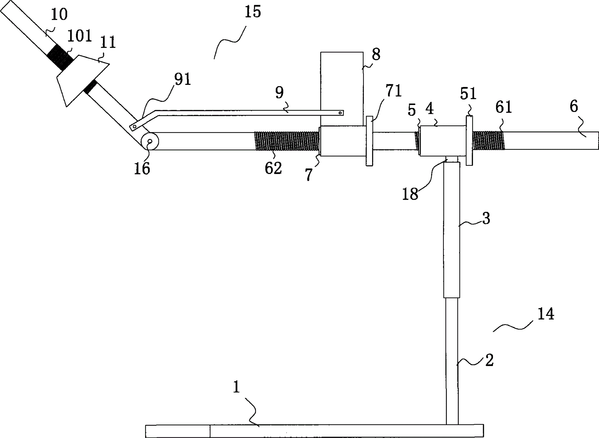
图1-1为本发明的结构示意图。Figure 1-1 is a schematic structural view of the present invention.
图1-2为本发明的剖视图。1-2 are cross-sectional views of the present invention.
图2为本发明的宫颈杯的结构示意图。Fig. 2 is a schematic structural view of the cervical cup of the present invention.
图3为本发明的底座与竖杆的连接结构示意图。Fig. 3 is a schematic diagram of the connection structure between the base and the vertical bar of the present invention.
图4为本发明的固定套与第一转动螺母的连接结构示意图。Fig. 4 is a schematic diagram of the connection structure between the fixing sleeve and the first rotating nut of the present invention.
图5为本发明的主螺杆与举宫螺杆的连接结构示意图。Fig. 5 is a schematic diagram of the connection structure between the main screw and the lifting screw of the present invention.
具体实施方式 Detailed ways
下面结合附图及实施例对本发明作进一步的描述。The present invention will be further described below in conjunction with the accompanying drawings and embodiments.
如图1-1和1-2所示,本发明的腹腔镜自助举宫器装置包括底座1及举宫器15,其中,举宫器15由竖杆14、主螺杆6及举宫螺杆10组成,竖杆14由固定螺母3、第一螺杆2及第二螺杆18组成,第一螺杆2的一侧设有第三螺纹22,第一螺杆2的一端连接在底座1上,另一端通过第三螺纹22与固定螺母3丝扣连接;第二螺杆18的一侧设有第四螺纹181,第二螺杆18的一端连接主螺杆6,主螺杆6上分别设有第一螺纹61和第二螺纹62。在主螺杆6与第二螺杆18之间设有固定套4,固定套4固定连接在第二螺杆18上,在固定套4内设有活动连接并限位在固定套4内的第一转动螺母5,第一转动螺母5的一侧设有第一环状突起51,第一转动螺母5通过设在主螺杆6上的第一螺纹61与主螺杆6之间丝扣连接;主螺杆6的前端螺杆上设有第二转动螺母7,第二转动螺母7上设有第二环状突起71,第二转动螺母7通过设在主螺杆6上的第二螺纹62与主螺杆6丝扣连接,在第二转动螺母7的外部设有活动连接的调向杆8,调向杆8将第二转动螺母7限位于调向杆8内,调向杆8上设有连杆9,连杆9设在调向杆8的左侧或右侧,连杆9的前端设有弯头91,主螺杆6的前端通过万向转轴16连接举宫螺杆10,弯头91连接举宫螺杆10,举宫螺杆10上设有第五螺纹101,宫颈塞11或宫颈杯12通过第五螺纹101与举宫螺杆10丝扣连接。As shown in Figures 1-1 and 1-2, the laparoscopic self-help uterine lifter device of the present invention includes a
如图2所示,宫颈杯12内设有颈管锥丝13,颈管锥丝13贯通宫颈杯12,颈管锥丝13位于宫颈杯12外的顶端设有调节钮131,颈管锥丝13内设有贯通调节钮131及颈管锥丝的通孔19,举宫螺杆10通过通孔19与颈管锥丝13丝扣连接。As shown in Figure 2, a
如图3所示,本发明底座1的前端为弧形结构,在底座1的后端中部设有第一螺杆2,在第一螺杆2上设有第三螺纹22,固定螺母3通过第三螺纹22与第一螺杆2丝扣连接。As shown in Figure 3, the front end of the
如图4所示,在第二螺杆18上设有第四螺纹181,第二螺杆18的上端固定连接固定套4,在固定套4内设有活动连接并限位在固定套4内的第一转动螺母5,在第一转动螺母5的一侧设有第一环状突起51。As shown in Figure 4, a
如图5所示,主螺杆6的前端螺杆上设有第二转动螺母7,第二转动螺母7上设有第二环状突起71,第二转动螺母7通过设在主螺杆6上的第二螺纹62与主螺杆6丝扣连接,在第二转动螺母7的外部设有活动连接的调向杆8,调向杆8将第二转动螺母7限位于调向杆8内,调向杆8上设有连杆9,连杆9的前端设有弯头91,主螺杆6的前端通过万向转轴16连接举宫螺杆10,弯头91连接举宫螺杆10,举宫螺杆10上设有第五螺纹101,宫颈塞11或宫颈杯12通过第五螺纹101与举宫螺杆10丝扣连接。As shown in Figure 5, the front screw rod of the
本发明使用时,将底座1放置于病人臀下,转动固定螺母3,固定螺母3将第一螺杆2及第二螺杆18向上下两端移动,调节腹腔镜自助举宫器装置的高度;第一转动螺母5活动于固定套4内,当转动第一环状突起51,第一环状突起51带动第一转动螺母5转动,主螺杆6前后移动,调整腹腔镜自助举宫器装置与病人的横向距离;当转动第二环状突起71时,第二环状突起71带动第二转动螺母7,连接在第二环状突起71外的调向杆8一起向前或向后运动,设在调向杆8上的连杆9带动举宫螺杆10上下摆动,调整调节腹腔镜自助举宫器装置与病人之间的角度;拨动调向杆8,带动连杆9沿主螺杆6环向转动,同时连杆9带动举宫螺杆10左右转动,调节腹腔镜自助举宫器装置与病人的环向角度;转动宫颈塞11将宫颈塞11塞在病人的宫腔内,通过第五螺纹101固定宫颈塞11的同时固定宫颈;或使用举宫杯12与其内有的颈管锥丝13,转动颈管锥丝,将举宫杯12固定在宫颈上,通过第五螺纹101将举宫杯固定在宫颈上,利用宫颈锥丝13固定宫颈。When the present invention is used, the
本发明的腹腔镜自助举宫器装置在腹腔镜手术时,通过主螺杆、第一转动螺母、第二转动螺母及调向杆控制举宫螺杆多方位控制,用于移动子宫方位、暴露视野,有利于盆腔、子宫或福建手术操作的自助举宫器,由腹腔镜的手术扶镜者操作,控制子宫的位置,操作简单,不需要另外专人负责,能够节省人力和手术时间,提高工作效率。The laparoscopic self-help uterine lifter device of the present invention is used for moving the uterus and exposing the field of view through the main screw, the first rotating nut, the second rotating nut and the steering rod to control the multi-directional control of the lifting screw during laparoscopic surgery. The self-service uterine lifter, which is beneficial to pelvic, uterine or Fujian operations, is operated by a laparoscopic operator to control the position of the uterus. The operation is simple and does not require another person to be responsible. It can save manpower and operation time and improve work efficiency.
Claims (1)
Priority Applications (1)
| Application Number | Priority Date | Filing Date | Title |
|---|---|---|---|
| CN 201010210199 CN101862216B (en) | 2010-06-25 | 2010-06-25 | Self-help uterine manipulator of laparoscope |
Applications Claiming Priority (1)
| Application Number | Priority Date | Filing Date | Title |
|---|---|---|---|
| CN 201010210199 CN101862216B (en) | 2010-06-25 | 2010-06-25 | Self-help uterine manipulator of laparoscope |
Publications (2)
| Publication Number | Publication Date |
|---|---|
| CN101862216A CN101862216A (en) | 2010-10-20 |
| CN101862216B true CN101862216B (en) | 2012-08-29 |
Family
ID=42954288
Family Applications (1)
| Application Number | Title | Priority Date | Filing Date |
|---|---|---|---|
| CN 201010210199 Expired - Fee Related CN101862216B (en) | 2010-06-25 | 2010-06-25 | Self-help uterine manipulator of laparoscope |
Country Status (1)
| Country | Link |
|---|---|
| CN (1) | CN101862216B (en) |
Families Citing this family (7)
| Publication number | Priority date | Publication date | Assignee | Title |
|---|---|---|---|---|
| CN102727287B (en) * | 2012-07-15 | 2014-06-25 | 浙江大学 | Womb lift fixing apparatus under laparoscope |
| CN104905852B (en) * | 2015-04-28 | 2017-10-10 | 中日友好医院 | A kind of intelligent multifunctional remote control uterus raising device |
| CN106691552A (en) * | 2015-11-18 | 2017-05-24 | 张晶 | Uterine manipulator and application method thereof |
| CN105943134B (en) * | 2016-06-08 | 2018-11-13 | 丽水市人民医院 | Semi-automatic uterus raising device |
| CN107997796B (en) * | 2018-01-05 | 2023-01-24 | 西安交通大学医学院第一附属医院 | Adjustable uterus lifting device |
| CN109700512B (en) * | 2019-02-13 | 2024-04-26 | 中南大学湘雅三医院 | Self-help uterine manipulator for laparoscope |
| CN114948145B (en) * | 2022-05-27 | 2023-03-31 | 深圳市妇幼保健院 | Automatic uterus lifter and method convenient for adjusting uterus position for laparoscopic surgery |
Citations (2)
| Publication number | Priority date | Publication date | Assignee | Title |
|---|---|---|---|---|
| CN1543916A (en) * | 2003-11-19 | 2004-11-10 | 星 周 | Mirror supporting device |
| CN2873114Y (en) * | 2005-12-08 | 2007-02-28 | 姚书忠 | Womb support device |
-
2010
- 2010-06-25 CN CN 201010210199 patent/CN101862216B/en not_active Expired - Fee Related
Patent Citations (2)
| Publication number | Priority date | Publication date | Assignee | Title |
|---|---|---|---|---|
| CN1543916A (en) * | 2003-11-19 | 2004-11-10 | 星 周 | Mirror supporting device |
| CN2873114Y (en) * | 2005-12-08 | 2007-02-28 | 姚书忠 | Womb support device |
Also Published As
| Publication number | Publication date |
|---|---|
| CN101862216A (en) | 2010-10-20 |
Similar Documents
| Publication | Publication Date | Title |
|---|---|---|
| CN101862216B (en) | Self-help uterine manipulator of laparoscope | |
| CN104840177B (en) | Multifunctional gynecological is diagnosed and operation device | |
| CN104905852B (en) | A kind of intelligent multifunctional remote control uterus raising device | |
| CN101569556A (en) | Laparoscope holding fixer | |
| CN116616688A (en) | A soft hysteroscope robot | |
| CN102197989A (en) | Intelligent electronic cystoscope system | |
| CN107997796B (en) | Adjustable uterus lifting device | |
| CN211325436U (en) | Puncture positioning device for clinical B-type ultramicro invasive surgery | |
| CN201987664U (en) | Laparoscope operation auxiliary frame | |
| CN201404228Y (en) | Examination bed for transcranial Doppler | |
| CN116138721A (en) | A colposcopy detection device | |
| CN115153847A (en) | A transvaginal hysteroscopic surgical robot and its control system | |
| CN109700512A (en) | A kind of self-help uterine manipulator of laparoscope | |
| CN219126610U (en) | Palace ware is lifted in supplementary HIFU ablation treatment | |
| CN210131057U (en) | Surgical examining table | |
| CN202173384U (en) | Multifunctional adjustable support laryngoscope | |
| CN103750903A (en) | Super-conduction gynecologic diagnosis and treatment table | |
| CN206167289U (en) | All -round operating table of obstetrical department | |
| CN106539619A (en) | A kind of resectoscope stabilizing mechanism | |
| CN111529023A (en) | A remote-controlled automatic palace lifter | |
| CN223614804U (en) | A combined speculum for hysteroscopic surgery | |
| CN203989522U (en) | Focus supersonic hysteromyoma therapeutic instrument | |
| CN218979023U (en) | Auxiliary device is sewed up to sacrospinous ligament | |
| CN206239878U (en) | Direct-view urethreurynter | |
| CN211834658U (en) | A multi-function lifting device |
Legal Events
| Date | Code | Title | Description |
|---|---|---|---|
| C06 | Publication | ||
| PB01 | Publication | ||
| C10 | Entry into substantive examination | ||
| SE01 | Entry into force of request for substantive examination | ||
| C14 | Grant of patent or utility model | ||
| GR01 | Patent grant | ||
| CF01 | Termination of patent right due to non-payment of annual fee |
Granted publication date: 20120829 Termination date: 20140625 |
|
| EXPY | Termination of patent right or utility model |