Detailed Description
The inventive concept will now be described more fully hereinafter with reference to the accompanying drawings, in which examples of embodiments of the inventive concept are shown. The inventive concept may be embodied in many different forms and should not be construed as limited to the embodiments set forth herein. Rather, these embodiments are provided so that this disclosure will be thorough and complete, and will fully convey the scope of the various inventive concepts to those skilled in the art. It should also be noted that these embodiments are not mutually exclusive. Components in one embodiment may be defaulted to exist in or for another embodiment.
Various embodiments disclosed herein relate to improvements in computer-aided navigation during surgery. An augmented reality (XR) headset is operably connected to a surgical system and is configured to provide an interactive environment through which a surgeon, assistant, and/or other personnel can view patient images and select among them, view computer-generated surgical navigation information, and select among them and/or control surgical instruments in an operating room. As described below, the XR headset may be configured to augment a real world scene with computer generated XR images. The XR headset may be configured to provide an enhanced real (AR) viewing environment by displaying a computer-generated XR image on a see-through display screen that allows light from a real-world scene to pass therethrough for combined viewing by a user. Alternatively, the XR headset may be configured to provide a Virtual Reality (VR) viewing environment by preventing or substantially preventing light from the real world scene from being directly viewed by the user when the user views the computer-generated AR image on the display screen. The XR headset may be configured to provide an AR and VR viewing environment. In one embodiment, both the AR and VR viewing environments are provided by lateral bands of substantially different opacity disposed between the see-through display and the real world scene, thereby providing a VR viewing environment for XR images aligned with high opacity bands and an AR viewing environment for XR images aligned with low opacity bands. In another embodiment, both the AR and VR viewing environments are provided by control of computer adjustable opacity filters that variably restrict how much light from the real world scene passes through the see-through display screen for combination with the XR images viewed by the user. Thus, XR headphones may also be referred to as AR headphones or VR headphones.
Fig. 1 depicts an embodiment of a surgical system 2 according to some embodiments of the present disclosure. Prior to performing an orthopedic or other surgical procedure, a planned surgical field of a patient may be scanned in three dimensions ("3D") using, for example, C-arm imaging device 104 of fig. 10 or O-arm imaging device 106 of fig. 11, or from another medical imaging device such as a Computed Tomography (CT) image or MRI. Such scanning may be performed pre-operatively (e.g., most often weeks prior to the procedure) or intra-operatively. However, any known 3D or 2D image scan may be used depending on the various embodiments of the surgical system 2. The image scan is sent to a computer platform in communication with the surgical system 2, such as computer platform 910 (fig. 9) of the surgical system 900, which surgical system 900 may contain a camera tracking system assembly 6, a surgical robot 4 (e.g., robot 2 in fig. 1), an imaging device (e.g., C-arm 104, O-arm 106, etc.), and an image database 950 for storing the image scan of the patient. A surgeon viewing one or more image scans on a display device of computer platform 910 (fig. 9) generates a surgical plan defining the object pose of a surgical tool used during a surgical procedure performed on the patient's anatomy. Exemplary surgical tools, also referred to as tools, may include, but are not limited to, drills, screwdrivers, retractors, and implants such as screws, spacers, interbody fusion devices, plates, rods, and the like. In some embodiments, a surgical plan defining a plane of the object is planned on a 3D image scan displayed on a display device.
As used herein, the term "pose" refers to the orientation and/or angle of rotation of one object (e.g., a dynamic reference array, an end effector, a surgical tool, an anatomical structure, etc.) relative to another object and/or a defined coordinate system. Thus, a gesture may be defined based on a multi-dimensional orientation of only one object with respect to another object and/or a defined coordinate system, based on a multi-dimensional rotation angle of only the object with respect to another object and/or a defined coordinate system, or a combination of multi-dimensional orientations and multi-dimensional rotation angles. Thus, the term "pose" is used to refer to an orientation, a rotation angle, or a combination thereof.
The surgical system 2 of fig. 1 may assist a surgeon during a medical procedure by, for example, holding tools, alignment tools, use tools, guidance tools, and/or positioning tools for use. In some embodiments, surgical system 2 includes surgical robot 4 and camera tracking system assembly 6. The ability to mechanically couple the surgical robot 4 and the camera tracking system assembly 6 may allow the surgical system 2 to be maneuvered and moved as a single unit and allow the surgical system 2 to have a small footprint in an area, allow easier movement through narrow aisles and around turns, and allow storage within a smaller area.
The surgical procedure may begin with the surgical system 2 being moved from the medical storage room to the medical procedure room. The surgical system 2 may be maneuvered through doorways, halls, and elevators to reach a medical procedure room. Within the medical procedure room, the surgical system 2 may be physically separated into two separate and distinct systems (surgical robot 4 and camera tracking system assembly 6). The surgical robot 4 may be positioned adjacent to the patient in any suitable location to properly assist medical personnel. The camera tracking system assembly 6 may be positioned at the bottom of the patient, at the patient's shoulder, or any other location suitable for tracking the current pose and pose movements of the surgical robot 4 and the tracked portion of the patient. Surgical robot 4 and camera tracking system assembly 6 may be powered by an on-board power source and/or plugged into an exterior wall outlet.
Surgical robot 4 may be used to assist a surgeon by holding and/or using tools during a medical procedure. To properly utilize and hold the tool, surgical robot 4 may rely on multiple motors, computers, and/or actuators to function properly. As illustrated in fig. 1, the robot body 8 may serve as a structure in which multiple motors, computers, and/or actuators may be fixed within the surgical robot 4. The robot body 8 may also provide support for a robotic telescoping support arm 16. The robot body 8 may be sized to provide a stable platform for supporting the attachment assembly and may house, hide, and protect a plurality of motors, computers, and/or actuators that may operate the attachment assembly.
The robot base 10 may serve as a lower support for the surgical robot 4. In some embodiments, the robot base 10 may support the robot body 8, and may attach the robot body 8 to a plurality of drive wheels 12. This attachment to the wheels may allow the robot body 8 to move efficiently in space. The robot base 10 may run along the length and width of the robot body 8. The robot base 10 may be about two inches to about 10 inches high. The robot base 10 may cover, protect and support the drive wheel 12.
In some embodiments, as illustrated in fig. 1, at least one drive wheel 12 may be attached to the robot base 10. The drive wheel 12 may be attached to the robot base 10 at any location. Each individual drive wheel 12 may rotate about a vertical axis in any direction. The motor may be disposed above, within, or adjacent to the drive wheel 12. Such motors may allow the surgical system 2 to be maneuvered to any position and stabilize and/or level the surgical system 2. The rod located within or adjacent to the drive wheel 12 may be pressed into the surface by a motor. The rod, not shown, may be made of any suitable metal to elevate the surgical system 2. The bar may lift the drive wheel 10, which may lift the surgical system 2 to any height required to level or otherwise fix the orientation of the surgical system 2 relative to the patient. The weight of the surgical system 2 is supported by the small contact area of the rods on each wheel, preventing the surgical system 2 from moving during the medical procedure. This rigid positioning may prevent objects and/or persons from accidentally moving the surgical system 2.
The robotic track 14 may be used to facilitate moving the surgical system 2. The robot track 14 provides the person with the ability to move the surgical system 2 without grasping the robot body 8. As illustrated in fig. 1, the length of the robot track 14 may be as long as the robot body 8, shorter than the robot body 8, and/or may be longer than the robot body 8. The robot track 14 may further provide protection to the robot body 8 from objects and/or medical personnel contacting, striking or hitting the robot body 8.
The robot body 8 may provide support for a selectively compliant articulating robotic arm, hereinafter referred to as "SCARA". The use of SCARA 24 within surgical system 2 may be advantageous due to the repeatability and compactness of the robotic arm. The compactness of SCARA may provide additional space within the medical procedure, which may allow a medical professional to perform the medical procedure without excessive clutter and limited area. SCARA 24 may include robotic telescoping support 16, robotic support arm 18, and/or robotic arm 20. A robot telescoping support 16 may be positioned along the robot body 8. As illustrated in fig. 1, the robotic telescoping support 16 may provide support for the SCARA 24 and the display 34. In some embodiments, the robotic telescoping support 16 may extend and retract in a vertical direction. The body of the robotic telescoping support 16 may be any width and/or height configured to support the stress and weight placed thereon.
In some embodiments, the medical personnel may move the SCARA24 through commands submitted by the medical personnel. As will be explained in further detail below, the commands may originate from inputs received on the display 34, tablet, and/or XR headset (e.g., headset 920 in fig. 9). The XR headset may eliminate the need for medical personnel to refer to any other display, such as the display 34 or a tablet computer, which enables the SCARA24 to be configured without the display 34 and/or the tablet computer. As will be explained in further detail below, the commands may be generated by pressing a switch and/or pressing a plurality of switches, and/or may be generated based on gesture commands and/or voice commands sensed by the XR headset.
As depicted in fig. 5, activation assembly 60 may include a switch and/or a plurality of switches. The activation assembly 60 may be operable to transmit movement commands to the SCARA24, allowing an operator to manually manipulate the SCARA 24. When the switch or switches are pressed, the medical personnel may have the ability to move the SCARA24 by the applied hand movements. Alternatively or additionally, as will be explained in further detail below, the operator may control movement of the SCARA24 by gesture commands and/or voice commands sensed by the XR headset. Additionally, when the SCARA24 does not receive a command to move, the SCARA24 may lock in place to prevent accidental movement by medical personnel and/or other objects. By locking in place, SCARA24 provides a secure platform by which end effector 26 may guide surgical tools during a medical procedure.
The robotic support arm 18 may be connected to the robotic telescoping support 16 by various mechanisms. In some embodiments, referring best to fig. 1 and 2, the robotic support arm 18 rotates in any direction relative to the robotic telescoping support 16. The robotic support arm 18 may rotate three hundred sixty degrees around the robotic telescoping support 16. The robotic arm 20 may be connected to the robotic support arm 18 in any suitable location and by various mechanisms that enable rotation in any direction relative to the robotic support arm 18. In one embodiment, the robotic arm 20 may be rotated three hundred sixty degrees relative to the robotic support arm 18. This free rotation allows the operator to position the robotic arm 20 according to the surgical plan.
The end effector 26 in fig. 4 and 5 is attached to the robotic arm 20 at any suitable location. The end effector 26 is configured to be attached to an end effector coupler 22 of a robotic arm 20 positioned by the surgical robot 4. The example end effector 26 includes a tubular guide that guides movement of an insertion surgical tool relative to an anatomy on which a surgical procedure is to be performed.
In some embodiments, dynamic reference array 52 is attached to end effector 26. Dynamic reference arrays (also referred to herein as "DRAs") are rigid bodies that can be placed on the anatomy (e.g., bone) of a patient, one or more XR headphones worn by personnel in an operating room, an end effector, a surgical robot, a surgical tool in a navigational surgical procedure. Computer platform 910, in combination with camera tracking system assembly 6 or other 3D positioning system, is configured to track the pose (e.g., azimuth and rotational orientation) of the DRA in real-time. The DRA may contain fiducials, such as the depicted arrangement of balls. Such tracking of the 3D coordinates of the DRA may allow the surgical system 2 to determine the pose of the DRA in any multi-dimensional space relative to the subject anatomy of the patient 50 in fig. 5.
As illustrated in fig. 1, the light indicator 28 may be positioned on top of the SCARA 24. The light indicator 28 may illuminate as any type of light to indicate a "condition" in which the surgical system 2 is currently operating. In some embodiments, the light may be generated by an LED light, which may form a ring around the light indicator 28. The light indicator 28 may comprise a completely permeable material that allows light to pass through the entire light indicator 28. The light indicator 28 may be attached to a lower display support 30. As illustrated in fig. 2, the lower display support 30 may allow an operator to manipulate the display 34 to any suitable position. The lower display support 30 may be attached to the light indicator 28 by any suitable mechanism. In some embodiments, the lower display support 30 may be rotatable about or rigidly attached to the light indicator 28. Upper display support 32 may be attached to lower display support 30 by any suitable mechanism.
In some embodiments, a tablet may be used in conjunction with the display 34 and/or without the display 34. The tablet may be disposed on the upper display support 32 in place of the display 34 and may be removable from the upper display support 32 during a medical procedure. In addition, the tablet may be in communication with a display 34. The tablet computer can be connected to the surgical robot 4 by any suitable wireless and/or wired connection. In some embodiments, the tablet computer is capable of programming and/or controlling the surgical system 2 during a medical procedure. When the surgical system 2 is controlled with a tablet computer, all input and output commands may be replicated on the display 34. The use of a tablet computer may allow an operator to manipulate surgical robot 4 without having to move around patient 50 and/or surgical robot 4.
As will be explained below, in some embodiments, the surgeon and/or other personnel may wear XR headphones that may be used in conjunction with the display 34 and/or tablet, or the XR headphones may eliminate the need to use the display 34 and/or tablet.
As depicted in fig. 3A and 5, the camera tracking system assembly 6 works in combination with the surgical robot 4 through a wired or wireless communication network. Referring to fig. 1, 3, and 5, the camera tracking system component 6 may include some components similar to the surgical robot 4. For example, the camera body 36 may provide functions found in the robot body 8. The robot body 8 may provide an auxiliary track bar on which the camera 46 is mounted. The structure within the robot body 8 may also provide support for electronics, communication devices, and power supplies for operating the camera tracking system assembly 6. The camera body 36 may be made of the same material as the robot body 8. The camera tracking system assembly 6 may communicate directly with the XR headset, tablet computer, and/or display 34 via a wireless and/or wired network to enable the XR headset, tablet computer, and/or display 34 to control the functions of the camera tracking system assembly 6.
The camera body 36 is supported by a camera mount 38. The camera mount 38 may be used as the robot mount 10. In the embodiment of fig. 1, the camera mount 38 may be wider than the robot mount 10. The width of the camera mount 38 may allow the camera tracking system assembly 6 to be coupled to the surgical robot 4. As depicted in fig. 1, the width of the camera mount 38 may be large enough to fit outside of the robot mount 10. The additional width of the camera mount 38 may allow the surgical system 2 to provide additional maneuverability and support for the surgical system 2 when the camera tracking system assembly 6 is coupled to the surgical robot 4.
As with the robot base 10, a plurality of drive wheels 12 may be attached to the camera base 38. Similar to the operation of the robot base 10 and the drive wheel 12, the drive wheel 12 may allow the camera tracking system assembly 6 to stabilize and level or set a fixed orientation relative to the patient 50. Such stabilization may prevent the camera tracking system assembly 6 from moving during a medical procedure and may prevent the camera 46 on the auxiliary tracking rod from losing track of the DRA connected to the XR headset and/or surgical robot 4, losing track of one or more DRAs 52 connected to anatomical structures 54 and/or tools 58 within the designated area 56 as depicted in fig. 3A and 5. This stability and maintenance of tracking enhances the ability of surgical robot 4 to operate effectively with camera tracking system assembly 6. Additionally, the wide camera mount 38 may provide additional support for the camera tracking system assembly 6. In particular, as depicted in fig. 3A and 5, the wide camera mount 38 may prevent the camera tracking system assembly 6 from tipping when the camera 46 is positioned over a patient.
The camera telescoping support 40 may support a camera 46 on the auxiliary track bar. In some embodiments, telescoping support 40 may move camera 46 higher or lower in a vertical direction. The camera handle 48 may be attached to the camera telescoping support 40 in any suitable location and configured to allow an operator to move the camera tracking system assembly 6 to a planned orientation prior to a medical procedure. In some embodiments, the camera handle 48 may be used to lower and raise the camera telescoping support 40. The raising and lowering of the camera telescoping support 40 may be performed by pressing a button, switch, lever, and/or any combination thereof by the camera handle 48.
The lower camera support arm 42 may be attached to the camera telescoping support 40 in any suitable location, in an embodiment, as depicted in fig. 1, the lower camera support arm 42 may be rotated three hundred sixty degrees around the telescoping support 40. Such free rotation may allow an operator to position camera 46 in any suitable location. The lower camera support arm 42 may be connected to the telescoping support 40 by any suitable mechanism. The lower camera support arm 42 may be used to provide support for a camera 46. The camera 46 may be attached to the lower camera support arm 42 by any suitable mechanism. The camera 46 may pivot in any direction at the attachment area between the camera 46 and the lower camera support arm 42. In an embodiment, the curved track 44 may be disposed on the lower camera support arm 42.
The curved track 44 may be positioned at any suitable location on the lower camera support arm 42. As illustrated in fig. 3A, the curved track 44 may be attached to the lower camera support arm 42 by any suitable mechanism. The curved track 44 may be any suitable shape, which may be crescent-shaped, circular, flat, oval, and/or any combination thereof. The camera 46 may be movably positioned along the curved track 44. The camera 46 may be attached to the curved track 44 by, for example, rollers, brackets, braces, motors, and/or any combination thereof. Motors and rollers, not shown, may be used to move camera 46 along curved track 44. As depicted in fig. 3A, during a medical procedure, if the subject prevents camera 46 from viewing the tracked one or more DRAs, the motor may responsively move camera 46 along curved track 44. Such motorized movement may allow camera 46 to move to a new position that is no longer obstructed by the subject without moving camera tracking system assembly 6. When camera 46 is blocked from viewing the one or more tracked DRAs, camera tracking system assembly 6 may send a stop signal to surgical robot 4, XR headset, display 34, and/or tablet computer. The stop signal may prevent movement of the SCARA 24 until the tracked DRA 52 has been reacquired by the camera 46 and/or may alert the operator to wear the XR headset and/or view the display 34 and/or tablet. This SCARA 24 may be configured to respond to receipt of the stop signal by stopping further movement of the base and/or end effector coupler 22 until the camera tracking system may resume tracking of the DRA.
Fig. 3B and 3C depict front and isometric views of another camera-camera tracking system assembly 6' that may be used with the surgical system of fig. 1 or that may be used independently of the surgical robot. For example, the camera tracking system assembly 6' may be used to provide navigational surgery without the use of robotic guidance. One of the differences between the camera tracking system assembly 6 'of fig. 3B and 3C and the camera tracking system assembly 6 of fig. 3A is that the camera tracking system assembly 6' of fig. 3B and 3C contains a housing for the transport computer platform 910. The computer platform 910 may be configured to: performing a camera tracking operation to track the DRA; performing a navigational surgical operation that provides surgical navigational information to a display device (e.g., an XR headset and/or other display device); and perform other computing operations disclosed herein. Thus, the computer platform 910 may include a navigation computer, such as one or more of the navigation computers of FIG. 14.
Fig. 6 depicts a block diagram view of components of the surgical system of fig. 5 for a medical procedure. Referring to fig. 6, the tracking camera 46 on the auxiliary tracking rod has a navigation field of view 600 in which the pose (e.g., azimuth and orientation) of the reference array 602 attached to the patient, the reference array 604 attached to the surgical instrument, and the robotic arm 20 are tracked. The tracking camera 46 may be part of the camera tracking system assembly 6' of fig. 3B and 3C that includes a computer platform 910 configured to perform the operations described below. The reference array performs tracking by reflecting light in a known pattern that is decoded by the tracking subsystem of surgical robot 4 to determine the corresponding pose of the reference array. If the line of sight between the patient reference array 602 and the tracking camera 46 on the auxiliary tracking rod is blocked (e.g., by medical personnel, instruments, etc.), further navigation of the surgical instrument may not be possible, and the responsive notification may temporarily stop further movement of the robotic arm 20 and surgical robot 4, display an alert on the display 34, and/or provide an audible alert to the medical personnel. The display 34 is available to the surgeon 610 and assistant 612, but viewing requires rotating the head away from the patient and changing the eye focus to a different distance and position. The navigation software may be controlled by the technician 614 based on voice instructions from the surgeon.
Fig. 7 illustrates various display screens that may be displayed by surgical robot 4 on display 34 of fig. 5 and 6 when using the navigation function of surgical system 2. The display screen may include, but is not limited to, various user selectable menus having overlaid graphical representations of patient radiographs, implant size parameters (e.g., length, width, and/or diameter) for controlling different phases of a surgical procedure, and virtual projections based on a developed surgical plan and/or based on the pose of a tracked reference array relative to an instrument model positioned in the display screen.
For navigational surgery, various processing components (e.g., computer platform 910) and associated software are provided that enable preoperative planning of a surgical procedure (e.g., implant placement) and electronic delivery of the plan to computer platform 910 to provide navigational information to one or more users during the planned surgical procedure, as described below.
For robotic navigation, various processing components (e.g., computer platform 910) and associated software are provided that enable preoperative planning of surgical procedures (e.g., implant placement) and electronic delivery of the plan to surgical robot 4, as described below. Surgical robot 4 uses a plan to guide robotic arm 20 and attached end effector 26 to provide an object pose of the surgical tool relative to the patient anatomy for the steps of the planned surgical procedure.
The following various embodiments relate to the use of one or more XR headsets that may be worn by surgeon 610, assistant 612, and/or other medical personnel to provide an improved user interface for receiving information from and/or providing control commands to surgical robots, camera tracking system assemblies 6/6', and/or other medical instruments in an operating room.
Fig. 8 depicts a block diagram of some electrical components of surgical robot 4, according to some embodiments of the present disclosure. Referring to fig. 8, a load cell (not shown) may be configured to track the force applied to end effector coupler 22. In some embodiments, the load cells may be in communication with a plurality of motors 850, 851, 852, 853, and/or 854. When the load cell senses a force, information about the amount of force applied may be distributed from the switch array and/or the plurality of switch arrays to the controller 846. The controller 846 may obtain force information from the load cells and process it with a switching algorithm. The controller 846 uses a switching algorithm to control the motor driver 842. The motor driver 842 controls the operation of one or more motors 850, 851, 852, 853, and/or 854. The motor driver 842 may direct a particular motor to generate an equal amount of force as measured by the load cell through the motor. In some embodiments, the force generated may be from multiple motors, such as 850-854, as directed by the controller 846. Additionally, the motor driver 842 may receive input from the controller 846. The controller 846 may receive information from the load cells regarding the direction of the force sensed by the load cells. Controller 846 may process this information using a motion controller algorithm. The algorithm may be used to provide information to a particular motor driver 842. To replicate the direction of the force, the controller 846 may activate and/or deactivate certain motor drives 842. The controller 846 may control one or more motors, such as one or more of 850-854, to induce movement of the end effector 26 in the direction of the force sensed by the load cells. Such force-controlled movement may allow an operator to move the SCARA 24 and end effector 26 with little effort and/or with very little resistance. Movement of the end effector 26 may be performed to position the end effector 26 in any suitable pose (i.e., position and angular orientation relative to a defined three-dimensional (3D) orthogonal reference axis) for use by medical personnel.
As best shown in fig. 5, the activation assembly 60 may be in the form of a bracelet wrapped around the end effector coupler 22. The activation assembly 60 may be positioned on any portion of the SCARA 24, any portion of the end effector coupler 22, may be worn (and wirelessly communicated) by medical personnel, and/or any combination thereof. The activation assembly 60 may include a primary button and a secondary button.
Pressing the primary button may allow the operator to move the SCARA 24 and end effector coupler 22. According to one embodiment, once in place, the SCARA 24 and end effector coupler 22 may not be moved until the operator programs the surgical robot 4 to move the SCARA 24 and end effector coupler 22, or the main buttons are used to move. In some examples, it may be desirable to press at least two non-adjacent primary activation switches before the SCARA 24 and end effector coupler 22 will respond to an operator command. Pressing at least two primary activation switches may prevent inadvertent movement of the SCARA 24 and end effector coupler 22 during a medical procedure.
Activated by the primary button, the load cell may measure the magnitude and/or direction of force exerted by an operator (i.e., medical personnel) on the end effector coupler 22. This information may be communicated to one or more motors, such as one or more of 850-854, within the SCARA 24 that may be used to move the SCARA 24 and end effector coupler 22. Information regarding the magnitude and direction of the force measured by the load cells may cause one or more motors (e.g., one or more of 850-854) to move the SCARA 24 and end effector coupler 22 in the same direction as sensed by the load cells. Such force-controlled movement may allow an operator to easily move the SCARA 24 and the end effector coupler 22, and may not require significant effort because the motor moves the SCARA 24 and the end effector coupler 22 while the operator moves the SCARA 24 and the end effector coupler 22.
In some examples, the operator may use the secondary button as a "select" device. During a medical procedure, surgical robot 4 may notify medical personnel of certain conditions via XR headset 920, display 34, and/or light indicator 28. XR headphones 920 are each configured to display an image on a see-through display screen to form an augmented reality image overlaid on a real-world object viewable through the see-through display screen. The surgical robot 4 may prompt medical personnel to select functions, modes, and/or evaluate the condition of the surgical system 2. Pressing the secondary button a single time may activate certain functions, modes and/or confirm information communicated to medical personnel via the XR headset 920, display 34 and/or light indicator 28. Additionally, pressing the secondary button multiple times in rapid succession may activate additional functions, modes, and/or select information communicated to medical personnel via the XR headset 920, display 34, and/or light indicator 28.
With further reference to fig. 8, the electrical components of surgical robot 4 include a platform subsystem 802, a computer subsystem 820, a motion control subsystem 840, and a tracking subsystem 830. Platform subsystem 802 includes a battery 806, a power distribution module 804, a connector panel 808, and a charging station 810. Computer subsystem 820 includes a computer 822, a display 824, and speakers 826. The motion control subsystem 840 includes drive circuitry 842, motors 850, 851, 852, 853, 854, stabilizers 855, 856, 857, 858, end effector connector 844, and controller 846. Tracking subsystem 830 includes an orientation sensor 832 and a camera transducer 834. Surgical robot 4 may also include a removable foot pedal 880 and a removable tablet 890.
The input power is supplied to the surgical robot 4 by a power source that may be provided to the power distribution module 804. The power distribution module 804 receives input power and is configured to generate different power supply voltages that are provided to other modules, components, and subsystems of the surgical robot 4. The power distribution module 804 may be configured to provide different voltage supplies to the connector panel 808, which may be provided to other components (e.g., computer 822, display 824, speaker 826, driver 842) to power, for example, motors 850-854 and end effector couplers 844, and to camera converter 834 and other components for the surgical robot 4. The power distribution module 804 may also be connected to a battery 806 that acts as a temporary power source if the power distribution module 804 does not receive power from an input power source. At other times, the power distribution module 804 may be used to charge the battery 806.
The connector panel 808 may be used to connect different devices and components to the surgical robot 4 and/or associated components and modules. The connector panel 808 may contain one or more ports that receive wires or connectors from different components. For example, connector panel 808 may have a ground port to ground surgical robot 4 to other devices, a port to connect foot pedal 880, a port to connect to tracking subsystem 830, which may contain an orientation sensor 832, a camera transducer 834, and a DRA tracking camera 870. The connector panel 808 may also contain other ports to allow USB, ethernet, HDMI communications with other components, such as the computer 822. According to some embodiments, connector panel 808 may include a wired and/or wireless interface for operatively connecting XR headset 920 to tracking subsystem 830 and/or computer subsystem 820.
The control panel 816 may provide various buttons or indicators that control the operation of the surgical robot 4 and/or provide information from the surgical robot 4 for viewing by an operator. For example, the control panel 816 may contain buttons for opening or closing the surgical robot 4, lifting or lowering the vertical column 16, and lifting or lowering the stabilizers 855-858, which may be designed to engage the casters 12 to lock the surgical robot 4 from physical movement. Other buttons may stop surgical robot 4 in the event of an emergency, which may remove all motor power and apply a mechanical brake to stop all movement from occurring. The control panel 816 may also have an indicator that informs the operator of certain system conditions (e.g., line power indicators) or the state of charge of the battery 806. According to some embodiments, one or more XR headsets 920 may communicate, for example, through connector panel 808, to control operation of surgical robot 4 and/or to receive and display information generated by surgical robot 4 for viewing by a person wearing XR headsets 920.
The computer 822 of the computer subsystem 820 contains an operating system and software for operating the designated functions of the surgical robot 4. The computer 822 may receive and process information from other components (e.g., the tracking subsystem 830, the platform subsystem 802, and/or the motion control subsystem 840) to display information to an operator. Further, computer subsystem 820 may provide an output to an operator through speaker 826. The speaker may be part of the surgical robot, part of the XR headset 920, or within another component of the surgical system 2. The display 824 may correspond to the display 34 depicted in fig. 1 and 2.
Tracking subsystem 830 may include an orientation sensor 832 and a camera transducer 834. Tracking subsystem 830 may correspond to camera tracking system component 6 of fig. 3. The DRA tracking camera 870 operates with the position sensor 832 to determine the pose of the DRA 52. Such tracking may be performed in a manner consistent with the present disclosure, including using infrared light or visible light technology, such as LEDs or reflective markers, that track the position of the active or passive elements of DRA 52, respectively.
The functional operations of tracking subsystem 830 and computer subsystem 820 may be contained in computer platform 910 that may be transported by camera tracking system component 6' of fig. 3A and 3B. Tracking subsystem 830 may be configured to determine gestures, such as the position and angular orientation of the tracked DRA. The computer platform 910 may also contain a navigation controller configured to use the determined pose to provide navigation information to the user that directs them to move the tracked tool relative to the azimuthally registered patient image and/or tracked anatomy during the planned surgical procedure. Computer platform 910 may display information on the display of fig. 3B and 3C and/or to one or more XR headphones 920. When used with a surgical robot, computer platform 910 may be configured to communicate with computer subsystem 820 and other subsystems of fig. 8 to control movement of end effector 26. For example, as will be explained below, computer platform 910 may generate a graphical representation of a patient's anatomy, surgical tool, user's hand, etc., having a displayed size, shape, color, and/or pose that is controlled based on the determined pose of one or more tracked DRAs, and the displayed graphical representation may be dynamically modified to track the change in the determined pose over time.
The motion control subsystem 840 may be configured to physically move the vertical column 16, the upper arm 18, the lower arm 20, or rotate the end effector coupler 22. Physical movement may be performed by using one or more motors 850-854. For example, the motor 850 may be configured to vertically raise or lower the vertical column 16. As depicted in fig. 2, motor 851 may be configured to move upper arm 18 laterally about the point of engagement with vertical column 16. As depicted in fig. 2, motor 852 may be configured to move lower arm 20 laterally about an engagement point with upper arm 18. Motors 853 and 854 may be configured to move end effector coupler 22 to provide translational movement along a three-dimensional axis and rotation thereabout. The computer platform 910 depicted in fig. 9 may provide control inputs to the controller 846 that direct movement of the end effector coupler 22 to position a passive end effector coupled thereto in a planned pose (i.e., position and angular orientation relative to a defined 3D orthogonal reference axis) relative to an anatomy to be operated upon during a planned surgical procedure. The motion control subsystem 840 may be configured to measure the orientation of the end effector coupler 22 and/or end effector 26 using an integrated orientation sensor (e.g., encoder).
Fig. 9 depicts a block diagram of components of a surgical system including an imaging device (e.g., C-arm 104, O-arm 106, etc.) connected to a computer platform 910 that may be operably connected to a camera tracking system component 6 (fig. 3A) or 6' (fig. 3B, 3C) and/or a surgical robot 4, according to some embodiments of the present disclosure. Alternatively, at least some of the operations disclosed herein as being performed by the computer platform 910 may additionally or alternatively be performed by components of a surgical system.
With reference to FIG. 9, the computer platform 910 includes a display 912, at least one processor circuit 914 (also referred to as a processor for brevity), at least one memory circuit 916 (also referred to as a memory for brevity) containing computer readable program code 918, and at least one network interface 902 (also referred to as a network interface for brevity). Display 912 may be part of XR headset 920 according to some embodiments of the present disclosure. The network interface 902 may be configured to connect to the C-arm imaging device 104 of fig. 10, the O-arm imaging device 106 of fig. 11, another medical imaging device, an image database 950 containing medical images of a patient, components of the surgical robot 4, and/or other electronics.
When used with surgical robot 4, display 912 may correspond to display 34 of fig. 2 and/or tablet 890 of fig. 8 and/or XR headset 920 operably connected to surgical robot 4, network interface 902 may correspond to platform network interface 812 of fig. 8, and processor 914 may correspond to computer 822 of fig. 8. The network interface 902 of the XR headset 920 may be configured to communicate over a wired network (e.g., a thin line ethernet) and/or over a wireless RF transceiver link in accordance with one or more wireless communication protocols (e.g., WLAN, 3GPP4G, and/or 5G (new radio) cellular communication standards, etc.).
Processor 914 may comprise one or more data processing circuits, such as a general-purpose and/or special-purpose processor, e.g., a microprocessor and/or a digital signal processor. Processor 914 is configured to execute computer-readable program code 918 in memory 916 to perform operations that may include some or all of the operations described herein as being performed for surgical planning, navigation surgery, and/or robotic surgery.
The computer platform 910 may be configured to provide surgical planning functionality. Processor 914 can be operative to display an image of an anatomical structure (e.g., vertebra) received from one of imaging devices 104 and 106 and/or from image database 950 via network interface 920 on display device 912 and/or XR headset 920. Processor 914 receives an operator definition of the location at which the anatomical structure depicted in the one or more images is to be subjected to the surgical procedure (e.g., screw placement), such as by the operator touching a location on selection display 912 for the planned surgical procedure or using a mouse-based cursor to define the location for the planned surgical procedure. As will be explained in further detail below, when displaying images in the XR headset 920, the XR headset may be configured to sense gesture-based commands formed by the wearer and/or to sense voice-based commands spoken by the wearer, which may be used to control selection between menu items and/or to control how objects are displayed on the XR headset 920.
The computer platform 910 may be configured to enable anatomical measurements that may be particularly useful for knee surgery, similar to measurements of various angles that determine hip center, angle center, natural landmarks (e.g., femoral condyle line (transepicondylar line), white line (whiteside line), femoral posterior condyle line (posterior condylar line), etc.). Some measurements may be automatic, but others may involve human input or assistance. The computer platform 910 may be configured to allow an operator to input a selection of the correct implant for the patient, including a selection of size and alignment. The computer platform 910 may be configured to perform automatic or semi-automatic (involving human input) segmentation (image processing) of CT images or other medical images. The patient's surgical plan may be stored in a cloud-based server, which may correspond to database 950, for retrieval by surgical robot 4.
For example, during an orthopedic procedure, a surgeon may select a site (e.g., posterior femur, proximal tibia, etc.) to cut using a computer screen (e.g., touch screen) or an augmented reality (XR) interaction (e.g., gesture-based commands and/or voice-based commands) through, for example, XR headset 920. The computer platform 910 may generate navigation information that provides visual guidance to a surgeon to perform a surgical procedure. When used with surgical robot 4, computer platform 910 may provide guidance that allows surgical robot 4 to automatically move end effector 26 to an object pose such that a surgical tool is aligned with an object position to perform a surgical procedure on an anatomical structure.
In some embodiments, the surgical system 900 may use two DRAs to track patient anatomical orientations, such as a DRA connected to a patient's tibia and a DRA connected to a patient's femur. The system 900 may use standard navigation instruments for registration and inspection (e.g., a pointer similar to the pointer used in Globus ExcelsiusGPS systems for performing spinal surgery).
A particularly challenging task in navigational surgery is how to plan the placement of implants in the spine, knee, and other anatomy where the surgeon strives to perform the task on a computer screen, which is a 2D representation of the 3D anatomy. The system 900 may solve this problem by displaying a three-dimensional (3D) computer-generated representation of the anatomy and the candidate implant device using the XR headset 920. Under the direction of computer platform 910, the computer-generated representations zoom and pose on the display screen relative to each other and may be manipulated by the surgeon as they view through XR headset 920. The surgeon may manipulate the displayed computer-generated representation of the anatomy, implant, surgical tool, etc., for example, using gesture-based commands and/or voice-based commands sensed by XR headset 920.
For example, the surgeon may view the displayed virtual handles on the virtual implant and may manipulate (e.g., grasp and move) the virtual handles to move the virtual implant to a desired pose and adjust the planned implant placement relative to the graphical representation of the anatomy. Thereafter, during surgery, computer platform 910 may display navigation information through XR headset 920 that facilitates the surgeon's ability to more accurately follow the surgical plan to insert the implant and/or perform another surgical procedure on the anatomy. When the surgical procedure involves bone removal, the progress of the bone removal (e.g., depth of cut) may be displayed in real time by XR headset 920. Other features that may be displayed by XR headset 920 may include, but are not limited to, gap or ligament balance along the range of articulation, contact lines on the implant along the range of articulation, ligament tension and/or relaxation rendered by color or other graphics, and the like.
In some embodiments, computer platform 910 may allow for planning the use of standard surgical tools and/or implants, such as posterior stabilized implants and cross-retaining implants, bone cement-type and non-bone cement-type implants, revision systems for procedures related to, for example, total or partial knee and/or hip replacement and/or trauma.
An automated imaging system may be used in conjunction with the
computer platform 910 to acquire pre-operative, intra-operative, post-operative, and/or real-time image data of an anatomical structure. Fig. 10 and 11 illustrate an example automated imaging system. In some embodiments, the automated imaging system is a C-arm 104 (FIG. 10) imaging device or O
106 (FIG. 11). (O->
Copyrights are obtained by the meiton force pilot company (Medtronic Navigation, inc.) which is located business by lewis ville, colorado, usa. It may be desirable to take x-rays of a patient from a plurality of different locations without requiring frequent manual repositioning of the patient that may be required in an x-ray system. The C-
arm 104 x-ray diagnostic device can address the problem of frequent manual repositioning and is well known in the medical arts of surgery and other interventional procedures. As shown in fig. 10, the C-arm includes an elongated C-shaped member terminating in opposite distal ends 112 of a "C" shape. The C-shaped member is attached to an
x-ray source 114 and an
image receiver 116. The space within the C-
arm 104 of the arm provides a physician with room to care for the patient that is substantially undisturbed by the x-ray support structure.
The C-arm is mounted such that the arm is capable of rotational movement in two degrees of freedom (i.e., about two perpendicular axes in a spherical motion). The C-arm is slidably mounted to the x-ray support structure, which allows for orbital rotational movement of the C-arm about its center of curvature, which may allow for selective vertical and/or horizontal orientation of the x-ray source 114 and the image receiver 116. The C-arm may also be rotatable in a lateral direction (i.e., in a perpendicular direction relative to the orbiting direction to enable selective adjustment of the positioning of the x-ray source 114 and the image receiver 116 relative to the width and length of the patient). The spherical rotation aspect of the C-arm device allows the physician to perform x-ray examinations on the patient at an optimal angle determined with respect to the particular anatomical condition being imaged.
O shown in FIG. 11
106 includes a
gantry housing 124 that may enclose an image capture portion that is not shown. The image capturing section includes an x-ray source section and/or an x-ray emitting section and an x-ray receiving section and/or an image receiving section, which may be disposed about one hundred eighty degrees from each other and mounted on a rotor (not shown) relative to the orbit of the image capturing section. The image capturing portion may be operable to rotate three hundred sixty degrees during image acquisition. The image capturing section may be rotated about a center point or axis, allowing image data of the patient to be acquired from multiple directions or in multiple planes.
O with
gantry housing 124
106 has a central opening for positioning around the object to be imaged, a radiation source rotatable around the interior of the
gantry housing 124, which may be adapted to project radiation from a plurality of different projection angles. The detector system is adapted to detect radiation at each projection angle, thereby acquiring object images from a plurality of projection planes in a quasi-simultaneous manner. The gantry may be attached to the support structure O +_ in a cantilever manner>

Support structures such as wheeled mobile carts with wheels. The positioning unit is preferably arranged in The computerized motion control system translates and/or tilts the gantry to a planned position and orientation. The gantry may include a source and a detector disposed opposite each other on the gantry. The source and detector may be fixed to a motorized rotator that can rotate the source and detector in combination with each other about the interior of the gantry. The source may be pulsed in multiple orientations and orientations in a partial and/or full three hundred sixty degree rotation to multi-plane image an object positioned inside the gantry. The gantry may further include a track and bearing system for guiding the rotor as it rotates, which may carry the source and detector. O->
Both and/or one of 106 and C-
arm 104 may be used as an automated imaging system to scan a patient and send information to
surgical system 2.
The images captured by the imaging system may be displayed on the XR headset 920 and/or the computer platform 910 of the surgical system 900, the surgical robot 4, and/or another display device of another component. XR headset 920 may be connected to one or more of imaging devices 104 and/or 106 and/or image database 950, for example, through computer platform 910, to display images therefrom. The user may provide control inputs (e.g., gesture and/or voice based commands) through XR headset 920 to control the operation of one or more of imaging devices 104 and/or 106 and/or image database 950.
Fig. 12 depicts a block diagram view of components of a surgical system including a pair of XR headphones 1200 and 1210 (head displays HMD1 and HMD 2), which may correspond to XR headphones 920 depicted in fig. 13 and operate in accordance with some embodiments of the present disclosure.
Referring to the exemplary scenario of fig. 12, both assistant 612 and surgeon 610 wear XR headphones 1210 and 1210, respectively. The assistant 612 is optional wearing an XR headset 1210. As will be described further below, XR headsets 1200 and 1210 are configured to provide an interactive environment through which a wearer may view and interact with information related to a surgical procedure. Such an interactive XR-based environment may eliminate the need for a technician 614 to be present in the operating room, and may eliminate the need to use the display 34 depicted in fig. 6. Each XR headset 1200 and 1210 may contain one or more cameras configured to provide additional sources for tracking DRA or other reference arrays attached to instruments, anatomy, end effector 26, and/or other instruments. In the example of fig. 12, XR headset 1200 has a field of view (FOV) 1202 for tracking DRA and other objects, XR headset 1210 has a FOV 1212 for tracking DRA and other objects that partially overlaps FOV 1202, and tracking camera 46 has another FOV 600 for tracking DRA and other objects that partially overlaps FOVs 1202 and 1212.
If one or more cameras are blocked from viewing a DRA attached to a tracked object (e.g., a surgical instrument), but the DRA is in view of one or more other cameras, the tracking subsystem 830 and/or the navigation controller 828 may continue to track the object seamlessly without losing navigation. Additionally, if the DRA is partially obscured from view from one camera, but the entire DRA is visible through multiple camera sources, the tracking inputs of the cameras may be combined to continue navigating the DRA. One of the XR headphones and/or tracking camera 46 may view and track the DRA on the other of the XR headphones to enable computer platform 910 (fig. 9 and 14), tracking subsystem 830, and/or another computing component to determine the pose of the DRA relative to, for example, XR headphones 1200/1210, tracking camera 46, and/or one or more defined coordinate systems of another coordinate system defined for the patient, table, and/or room.
XR headsets 1200 and 1210 may be operably connected to view video, pictures, and/or other information received from an operating room and/or to provide commands to control various instruments in the operating room, including but not limited to nerve monitoring, microscopy, cameras, and anesthesia systems. Data from various instruments may be processed and displayed within the headset, for example, to display vital signs of the patient or microscopic feeds.
Exemplary XR headset assemblies and integration with navigational surgery, surgical robots, and other instruments
Fig. 13 illustrates an XR headset 920 configured according to some embodiments of the disclosure. The XR headset includes a headband 1306 configured to secure the XR headset to the wearer's head, an electronics package housing 1304 supported by the headband 1306, and a display screen 1302 extending laterally and downward from the electronics package housing 1304. The display screen 1302 may be a see-through LCD display device or semi-reflective lens that reflects an image projected by the display device toward the wearer's eye. A set of DRA references, e.g., points, are drawn or attached to one or both sides of the headset in a spaced apart, known manner. The DRA on the headset enables a tracking camera on the auxiliary track bar to track the pose of the headset 920 and/or enables another XR headset to track the pose of the headset 920.
The display 1302 operates as a see-through display (also referred to as a combiner) that reflects light from a display panel of the display device toward the eyes of the user. The display panel may be positioned between the electrical component housing and the user's head and angled to project virtual content toward the display screen 1302 to reflect toward the user's eyes. The display screen 1302 is semi-transparent and semi-reflective, allowing the user to see the reflected virtual content overlaid on the user's view of the real world scene. The display 1302 may have different opacity zones, for example, the upper side band is depicted as having a higher opacity than the lower side band. The opacity of the display screen 1302 may be electronically controlled to adjust how much light from the real world scene passes through the user's eyes. The high opacity configuration of display screen 1302 causes the high contrast virtual image to be overlaid on a dimmed view of the real world scene. The low opacity configuration of the display screen 1302 may cause a more blurred virtual image to be overlaid on a clearer view of the real world scene. Opacity may be controlled by applying an opaque material on the surface of display 1302.
According to some embodiments, the surgical system includes an XR headset 920 and an XR headset controller, such as controller 1430 in fig. 14 or controller 1430 in fig. 15. XR headset 920 is configured to be worn by a user during a surgical procedure and has a see-through display 1302 configured to display an XR image and allow at least a portion of a real world scene to pass therethrough for viewing by the user. XR headset 920 also includes an opacity filter positioned between at least one of the user's eyes and the real world scene when see-through display 1302 for viewing by the user. The opacity filter is configured to provide opacity to light from the real world scene. The XR headset controller is configured to communicate with a navigation controller (e.g., one or more controllers 828A, 828B, and/or 828C in fig. 14) to receive navigation information from the navigation controller that provides guidance to the user during a surgical procedure performed on an anatomical structure, and is further configured to generate an XR image for display on the see-through display screen 1302 based on the navigation information.
The opacity of the display screen 1302 may be configured to have a gradient of more continuously varying opacity down the top of the display screen 1302 with distance. The darkest point of the gradient may be at the top portion of the display screen 1302 and gradually become less transparent further down on the display screen 1302 until the opacity is transparent or is absent. In further exemplary embodiments, the gradient may change from about 90% opacity to completely transparent at about the mid-eye level of the display screen 1302. With the headset properly aligned and placed, the mid-eye level may correspond to the point at which the user will look straight, and the end of the gradient will be positioned at the "horizontal" line of the eye. The darker portion of the gradient will allow clear and definite vision of the virtual content and help block the invasive brightness of the overhead operating room lights.
Using an opacity filter in this manner enables XR headset 920 to provide Virtual Reality (VR) functionality by substantially or completely blocking light from the real world scene along an upper portion of display screen 1302 and AR functionality along a middle or lower portion of display screen 1302. This allows the user to have a translucent AR where needed and during the procedure, allowing for the use of clear optics for the patient anatomy. Configuring opacity filter 1302 as a gradient rather than a more constant opacity band may enable the wearer to experience a more natural transition between a more VR type of view and a more AR type of view without experiencing abrupt changes in the brightness of the real world scene and depth of field that may otherwise fatigue the eyes as during a more rapid shift between the top and bottom views.
The display panel and display screen 1302 may be configured to provide a wide field of view perspective XR display system. In one exemplary configuration, they provide the user with an 80 ° diagonal field of view (FOV) and 55 ° vertical coverage for the user to view virtual content. Other diagonal FOV angles and vertical coverage angles may be provided by different sizes of display panels, different curvatures of lenses, and/or different distances and angular orientations between the display panel and curved display screen 1302.
Fig. 14 depicts electrical components of an XR headset 920, which may be operably connected to a computer platform 910, one or more of the imaging devices (e.g., C-arm imaging device 104, O-arm imaging device 106), and/or an image database 950 and/or surgical robot 800, according to some embodiments of the disclosure.
XR headset 920 provides an improved human-machine interface for performing navigational surgical procedures. XR headset 920 may be configured to provide functionality, for example, via computer platform 910, including, but not limited to, any one or more of: recognition of gesture-based commands and/or voice-based commands displays XR graphical objects on display device 1450. Display device 1450 may be a video projector, flat panel display, or the like, that projects a displayed XR pattern object onto display screen 1302. The user may anchor the XR graphic object as an overlay to a particular real world object viewed through display screen 1302 (fig. 13). XR headset 920 may additionally or alternatively be configured to display video feeds from cameras mounted to one or more XR headsets 920 and other cameras on display 1450.
The electrical components of the XR headset 920 may include multiple cameras 1440, microphones 1442, gesture sensors 1444, gesture sensors (e.g., inertial Measurement Units (IMUs)) 1446, display modules 1448 including display devices 1450, and wireless/wired communication interfaces 1452. As described below, the XR headset camera 1440 may be a visible light capturing camera, a near infrared capturing camera, or a combination of both.
The camera 1440 may be configured to operate as a gesture sensor 1444 by capturing a user gesture for recognition performed within the field of view of the camera 1440. Alternatively, gesture sensor 1444 may be a proximity sensor and/or a touch sensor that senses a gesture performed by proximity gesture sensor 1444 and/or that senses physical contact (e.g., a tap sensor or housing 1304). Gesture sensor 1446 (e.g., IMU) may include a multi-axis accelerometer, a tilt sensor, and/or another sensor that may sense rotation and/or acceleration of XR headset 920 along one or more defined coordinate axes. Some or all of these electrical components may be contained in a component housing 1304 or may be contained in another housing configured to be worn elsewhere, such as on the buttocks or shoulders.
As described above, surgical system 2 includes camera tracking system components 6/6' and tracking subsystem 830, which may be part of computer platform 910. The surgical system may include an imaging device (e.g., C-arm 104, o-arm 106, and/or image database 950) and/or surgical robot 4. Tracking subsystem 830 is configured to determine a pose of a DRA attached to an anatomy, end effector, surgical tool, etc. The navigation controller 828 is configured to determine an object pose of the surgical tool relative to the anatomy based on the surgical plan, e.g., defining a location on the anatomy at which the surgical procedure is to be performed using the surgical tool based on the pose of the anatomy determined by the tracking subsystem 830 according to the surgical planning functions performed by the computer platform 910 of fig. 9. The navigation controller 828 may be further configured to generate steering information based on the object pose of the surgical tool, the pose of the anatomical structure, and the pose of the surgical tool and/or the end effector, wherein the steering information indicates where the surgical tool and/or the end effector of the surgical robot should be moved to execute the surgical plan.
The electrical components of XR headset 920 may be operably connected to the electrical components of computer platform 910 through a wired/wireless interface 1452. The electrical components of XR headset 920 may be operably connected, for example, through computer platform 910 or directly connected to various imaging devices (e.g., C-arm imaging device 104, I/O-arm imaging device 106), image database 950, and/or other medical instruments through wired/wireless interface 1452.
Surgical system 2 further includes at least one XR headset controller 1430 (also referred to as an "XR headset controller" for brevity), which XR headset controller 1430 may reside in an XR headset 920, computer platform 910, and/or another system component connected via a wired cable and/or wireless communication link. The various functions are provided by software executed by XR headset controller 1430. The XR headset controller 1430 is configured to receive navigational information from the navigational controller 828 that provides guidance to the user during surgical procedures performed on the anatomy and is configured to generate XR images for projection on the see-through display screen 1302 based on the navigational information displayed on the display device 1450.
The configuration of display device 1450 relative to display screen (also referred to as a "see-through display screen") 1302 is configured to display XR images in such a manner: so that when a user wearing XR headset 920 views through display screen 1302, the XR image appears to be in the real world. The display screen 1302 may be positioned in front of the eyes of the user by a headband 1306.
XR headset controller 1430 may be inside a housing configured to be worn on the user's head or elsewhere on the user's body when viewing display screen 1302, or may be located remotely from the user viewing display screen 1302 when communicatively connected to display screen 1302. XR headset controller 1430 may be configured to operably process signaling from camera 1440, microphone 142, and/or gesture sensor 1446, and connected, for example, through display module 1302 to display an XR image on display screen 1450. Thus, XR headset controller 1430, which is depicted as a circuit block within XR headset 920, is understood to be other depicted components operatively connected to XR headset 920, but not necessarily residing within a common housing (e.g., electrical component housing 13 of fig. 1304) or otherwise being portable by a user. For example, AR headset controller 1430 may reside within computer platform 910, which in turn may reside within the housing of computer tracking system 6' depicted in fig. 3B and 3C.
Exemplary XR headset Assembly optical arrangement
Fig. 15 depicts a block diagram showing an arrangement of optical components of an XR headset 920, according to some embodiments of the disclosure. Referring to FIG. 15, display device 1450 is configured to display an XR image generated by XR headset controller 1430, light from which is projected as XR image 1450 onto display screen 1302. The display screen 1302 is configured to combine light of the XR image 1450 and light from the real world scene 1502 into a combined enhanced view 1504, the enhanced view 1504 being directed to an eye 1510 of a user. The combiner 1302 configured in this manner operates as a see-through display screen. XR headset 920 may include any number of tracking cameras 1440. The camera 1440 may be a visible light capturing camera, a near infrared capturing camera, or a combination of both.
Exemplary user View through XR headphones
XR headset operation may display a 2D image and a 3D model on display screen 1302. The 2D image may preferably be displayed in a less transparent band of the display screen 1302 (upper band), and the 3D model may more preferably be displayed in a more transparent band of the display screen 1302 otherwise referred to as the environment area (bottom band). Below the lower band at the end of the display 1302, the operating room is unobstructed by the wearer. Note that the XR content displayed on display 1302 may be a fluid. The 3D content may move to the opaque band depending on the orientation of the headphones relative to the content, and the 2D content may be placed in the transparent band and stable relative to the real world. Additionally, the entire display screen 1302 may be darkened under electrical control to convert the headset to a virtual reality for surgical planning or to be completely transparent during a medical procedure. As explained above, XR headset 920 and associated operations not only support navigation procedures, but may also be performed in conjunction with robotic-assisted procedures.
Fig. 16 depicts an exemplary view of a display screen 1302 through an XR headset 920 for providing navigational assistance to a user manipulating a surgical tool 1602 during a medical procedure, according to some embodiments of the present disclosure. Referring to fig. 16, when the surgical tool 1602 is brought into proximity with the tracked anatomy such that the reference arrays 1630 and 1632 connected to the surgical tool 1602 are within the field of view of the cameras 1440 (fig. 15) and 46 (fig. 6), the graphical representation 1600 of the tool may be displayed in 2D and/or 3D images relative to the graphical representation 1610 of the anatomy. The user may adjust the trajectory 1620 of the surgical tool 1602 using the viewed graphical representation, which trajectory 1620 may be depicted as a graphical representation 1610 extending from the graphical representation 2000 of the tool through the anatomical structure. XR headset 920 may also display text information and other objects 1640. Dashed lines 1650 extending across the viewed display screen represent exemplary divisions between upper and lower bands of different opacity levels.
Other types of XR images (virtual content) that may be displayed on display 1302 may include, but are not limited to, any one or more of the following:
i) A 2D axial, sagittal, and/or coronal view of patient anatomy;
2) An overlay of planned tool and surgical implant positions versus currently tracked tool and surgical implant positions;
3) A preoperative image library;
4) Video feeds or remote video conferences from microscopes and other similar systems;
5) Options and configuration settings and buttons.
6) A floating 3D model of patient anatomy with surgical planning information;
7) Real-time tracking of surgical instruments relative to floating patient anatomy;
8) An enhanced overlay of patient anatomy with instructions and guidance; and
9) Enhanced coverage of the surgical instrument.
Exemplary configuration of a video Camera for tracking System Components
FIG. 17 depicts an exemplary configuration of an auxiliary track bar 46 having two pairs of stereoscopic tracking cameras configured in accordance with some embodiments of the present disclosure; the auxiliary track bar 46 is part of the camera tracking system assembly of fig. 3A, 3B and 3C. According to one embodiment, a stereoscopic tracking camera includes a pair of stereoscopic spaced apart visible light capturing cameras and another pair of stereoscopic spaced apart near infrared capturing cameras. Alternatively, only one pair of visible light capturing cameras or only one pair of near infrared capturing cameras may be used in the auxiliary track bar 46. Any of a number of near infrared and/or visible light cameras may be used.
Posture measuring chain
As described above, the navigational procedure may involve computer vision tracking and determining the pose (e.g., position and orientation in a six degree of freedom coordinate system) of the surgical instrument, for example, by determining the pose of an attached DRA that involves spaced apart fiducials, such as discs or spheres, arranged in a known manner. Computer vision uses spaced apart tracking cameras, such as stereoscopic cameras, configured to capture near infrared and/or visible light. In this scenario, there are three parameters in common competing for optimization: (1) precision, (2) robustness, and (3) user ergonomics during surgical procedures.
Some further aspects of the present disclosure relate to computer operations that combine (chain) measurement gestures in a manner that can improve optimization of one or more of the three parameters described above by incorporating an additional tracking camera mounted to one or more XR headphones. As shown in fig. 17, a pair of stereoscopic visible tracking cameras and another pair of stereoscopic near-infrared tracking cameras may be attached to an auxiliary track bar of a camera tracking system assembly according to some embodiments of the present disclosure. An operational algorithm is disclosed that analyzes the pose of a DRA that is fully or partially observed (e.g., when all references to the DRA are not observed by a pair of stereoscopic cameras) and combines the observed pose or partial pose in a manner that can improve accuracy, robustness, and/or ergonomics during a navigational procedure.
As described above, the XR headset may be configured to augment a real world scene with computer generated XR images. The XR headset may be configured to provide an XR viewing environment by displaying computer-generated XR images on a see-through display screen that allows light from a real-world scene to pass therethrough for combined viewing by a user. Alternatively, the XR headset may be configured to provide a VR viewing environment by preventing or substantially preventing light from the real world scene from being viewed directly by the user along the viewing path of the displayed XR image. The XR headset may be configured to provide an AR and VR viewing environment. In one embodiment, both the AR and VR viewing environments are provided by lateral bands of substantially different opacity disposed between the see-through display and the real world scene, thereby providing a VR viewing environment for XR images aligned with high opacity bands and an AR viewing environment for XR images aligned with low opacity bands. In another embodiment, both the AR and VR viewing environments are provided by control of computer adjustable opacity filters that variably restrict how much light from the real world scene passes through the see-through display screen for combination with the XR images viewed by the user. Thus, XR headphones may also be referred to as AR headphones or VR headphones.
As also described above, the XR headset may include a near infrared tracking camera and/or a visible light tracking camera configured to track fiducials of DRAs connected to the surgical instrument, patient anatomy, other XR headsets, and/or robotic end effectors. The use of near infrared tracking and/or visible light tracking on an XR headset provides additional tracking volume coverage beyond that provided by a camera on a single auxiliary track bar. Adding a near infrared tracking camera to an existing auxiliary tracking bar allows tracking the headset position more robustly but less accurately than in the visible light. The mechanical calibration visible and near infrared tracking coordinate systems enable the coordinate systems to be sufficiently aligned to perform 3D DRA reference triangulation operations using stereo matching to collectively identify the pose of the DRA reference between the visible and near infrared tracking coordinate systems. Any one or more of the following may be enabled using the visible and near infrared tracking coordinate systems: (a) identifying a tool that is not identifiable using a single coordinate system; (b) improving gesture tracking accuracy; (c) Achieving a wider range of motion without losing tracking of the surgical instrument, patient anatomy, and/or robotic end effector; and (d) naturally tracking the XR headset in the same coordinate system as the surgical instrument being navigated.
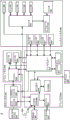
Fig. 18 depicts a block diagram of the components of a surgical system including a pair of tracking cameras in XR headphones 1200 and 1210 (head mounted displays HMD1 and HMD 2) and a tracking camera in a camera tracking system component 6' housing a computer platform 910. The computer platform 910 may include a tracking subsystem 830, a navigation controller 828, and an XR headset controller 1430, as previously shown in fig. 14.
Referring to the surgical system of fig. 18, both the surgeon and the assistant wear XR headphones HMD1 1200 and HMD2 1210, respectively, each containing a tracking camera that can be configured as shown in fig. 13. The assistant wears XR headset HMD2 1210 is optional.
The combination of the XR headphones HMD1 1200 and HMD2 1210 with the tracking camera 46 on the auxiliary tracking rod may more robustly track exemplary objects of the patient reference array (R), robotic end effector (E), and surgical tool (T) or instrument when operated with the computer platform 910. Overlapping views from different perspectives provided by the XR headphones HMD1 and HMD2 1210 and the tracking camera 46 on the auxiliary track bar are depicted in fig. 12.
Each of the items marked in fig. 18 represents a unique coordinate system. The description of the coordinate system label is as follows:
a=the visible light coordinate system of the second headphone HMD2 1210;
n3=the NIR coordinate system of the second headphone HMD2 1210;
s=the visible light coordinate system of the main headphone HMD1 1200;
n2=the NIR coordinate system 1200 of the main headphone HMD 1;
n=nir coordinate system of auxiliary navigation bar 46;
v = visible light coordinate system of auxiliary navigation bar 46;
r = patient reference NIR coordinate system of the fiducial array 602;
t = NIR coordinate system of tracked tool 604;
e = NIR coordinate system of tracked robotic end effector on robotic arm 20; and
w = inertial navigation world coordinate system with steady gravity vector.
During manufacturing, the spatial relationship (and by extension, coordinate system) of some of these marker objects may be measured and calibrated when the instrument is installed in an operating room, and/or before the surgical procedure is to be performed. In the disclosed system, the following coordinate system is calibrated:
wherein the term "T" is defined as a six degree of freedom (6 DOF) homogeneous transformation between two illustrated coordinate systems. Thus, for example, item- >
Is a 6DOF homogeneous transformation between the visible light coordinate system of the primary headphone HMD11200 and the NIR coordinate system of the
primary headphone HMD1 1200.
In one embodiment, XR headphones HMD1 and HMD2 1200 and 1210 have passive visible light markers (coordinate systems S and a), such as DRA fiducial 1310, depicted or otherwise attached thereto, as shown in fig. 13. The tracking camera is spatially calibrated to these passive references (coordinate systems N2 and N3).
As described above, the cameras on the XR headphones HMD11200 and HMD2 1210 and the tracking camera 46 on the auxiliary tracking rod have partially overlapping fields of view. If one or more cameras on XR headset HMD11200 are blocked from viewing a DRA attached to a tracked object, such as tracked tool (T), but the DRA is within view of the camera of another XR headset HMD2 1210 and/or tracking camera 46 on the secondary tracking stick, computer platform 910 may continue to track the DRA seamlessly without losing navigation. In addition, if there is partial occlusion of the DRA from the perspective of the camera on the XR headset HMD11200, but the entire DRA is visible via the camera of another XR headset HMD2 1210 and/or tracking camera 46 on the auxiliary tracking stick, the tracking inputs of the cameras may be combined to continue navigation of the DRA.
More specifically, by independently viewing the various camera systems provided by the XR headphones HMD1 1200 and HMD2 1210 and the tracking camera 46 on the auxiliary tracking rod, the various coordinate systems may be linked together. For example, each of XR headphones HMD1 1200 and HMD2 1210 may require virtual enhancement of robotic end effector (E). While the tracking camera 46 on one XR headset HMD1 1200 (N2) and auxiliary tracking bar (N) is visible (E), it is possible that the other XR headset HMD2 1210 (N3) is not visible. (E) The position relative to (N3) can still be calculated by one of several different methods of operation. Operations according to one embodiment perform linking of gestures from a patient reference (R). If the patient reference (R) is seen by either (N3) and (N) or (N2), the pose of (E) relative to (N3) can be solved directly by either of the following two equations:
The key to this pose chain is to infer the relationship between frames at the end of each chain (circled and transmitted below). These chains may be of any length and are implemented by having more than one stereo camera system (e.g., N, N, N3).
FIG. 21 is a flowchart of corresponding operations that may be performed by a camera tracking system, according to some embodiments. Referring to fig. 21, a camera tracking system may be configured to receive 2100 tracking information related to a tracked object from a first tracking camera (e.g., N3) and a second tracking camera (e.g., N2) during a surgical procedure. The camera tracking system may determine 2102 a first pose transformation (e.g.,
). The camera tracking system may determine 2104, e.g.,/based on first object tracking information from a second tracking camera (e.g., N2) indicating a pose of a first object (e.g., R)>
A second pose transformation between the first object (e.g., R) coordinate system and the second tracking camera (e.g., N2) coordinate system. The camera tracking system may determine 2106, for example, based on second object tracking information from a second tracking camera (e.g., N2) indicative of a pose of a second object (e.g., E)
A third pose transformation between the second object (e.g., E) coordinate system and the second tracking camera (e.g., N2) coordinate system. The camera tracking system may determine 2108 (e.g., +. >
) A fourth pose transformation between the second object (e.g., E) coordinate system and the first tracking camera (e.g., N3) coordinate system.
In some further embodiments, the camera system may further determine 2110 the pose of the second object (e.g., E) and the first tracking camera system (e.g., N3) coordinate system based on processing the tracking information through a fourth pose transformation.
Due to the overlapping fields of view of the various camera systems, the camera tracking system is able to determine the pose of the second object (e.g., E) relative to the first tracking camera (e.g., N3) when the first camera is blocked from seeing the second object (e.g., E). In some embodiments, for example, the camera tracking system is further configured to determine a fourth pose transformation (e.g.,
) Without using any tracking information from the first tracking camera (e.g., N3) indicating the pose of the second object (e.g., E).
The camera tracking system may be further configured to track the first object (e.g., R) based on processing tracking information from the first tracking camera (e.g., N3) indicative of the pose of the first object (e.g., R) via a fourth pose transformation, based on processing the first object (e.g., R) via the fourth pose transformation (e.g.,
) Processing of tracking information from the second tracking camera (e.g., N2) indicative of the pose of the first object (e.g., R), and determining the pose of the second object (e.g., E) in the first tracking camera (e.g., N3) coordinate system based on processing of tracking information from the second tracking camera (e.g., N2) indicative of the pose of the second object (E) by the fourth pose transformation.
The camera tracking system may achieve higher tracking accuracy by merging synchronized images from multiple camera systems. For example, the camera tracking system may determine the pose of a second object (e.g., E) relative to a first tracking camera (e.g., N3) by merging synchronized images of the second object (e.g., E) from multiple perspectives (first and second tracking cameras), and may use a cameraTo weight determined based on the accuracy specifications of the individual cameras. More specifically, the camera tracking system may be further configured to determine a fourth pose transformation (e.g.,
)。
The tracking system may be further configured to apply a second weight to the first and second object tracking information (e.g., N2) from the second tracking camera based on applying the first weight to the first and second object tracking information from the first tracking camera (e.g., N3), and to transform (e.g.,
) The first weighted first and second object tracking information from the first tracking camera and the second weighted first and second object tracking information from the second tracking camera are processed to determine a pose (e.g., E) of the second object. The value of the first weight represents the pose determination accuracy of the first tracking camera (e.g., N3), and the value of the second weight represents the pose determination accuracy of the second tracking camera (e.g., N2).
The camera tracking system may be further configured to adjust the value of the first weight over time in response to a change in the pose determination accuracy of the first tracking camera (e.g., N3) determined during operation of the camera tracking system, and to adjust the value of the second weight over time in response to a change in the pose determination accuracy of the second tracking camera (e.g., N2) determined during operation of the camera tracking system.
The camera tracking system may be configured to: reducing a value of the first weight based on determining that the pose determination accuracy of the first tracking camera (e.g., N3) has decreased; and increasing the value of the first weight based on determining that the pose determination accuracy of the first tracking camera (e.g., N3) has increased.
The camera tracking system may be further configured to adjust a value of at least one of the first and second weights over time in response to a determined change in pose determination accuracy of the first tracking camera (e.g., N3) relative to pose determination accuracy of the second tracking camera (e.g., N2) during operation of the camera tracking system.
The surgical system may be configured to display an XR image having a pose determined based on the fourth pose transformation on a see-through display screen of the XR headset. The camera tracking system may be further configured to generate an XR image as a graphical representation of a second object (e.g., E) gesturing on the see-through display based on processing the fourth pose transformation of the first object tracking information from the first and second tracking cameras and the second object tracking information from the second tracking camera.
As described above, the camera tracking system may include a navigation controller 828 communicatively connected to the first tracking camera (e.g., N3) and the second tracking camera (e.g., N2) to receive tracking information and configured to perform the determination of the first, second, third, and fourth pose transforms.
Fig. 19 illustrates another scenario in which occlusion prevents cameras on both XR headphones from directly seeing all DRA references attached to the end effector (E), and related pose chain operations that can be performed to fully resolve the pose of the end effector (E) relative to the other tracked DRA (e.g., R). Even if the navigation instrument (e.g., T) or end effector (E) is not seen or identified by any XR headset camera, the navigation instrument (e.g., T) or end effector (E) may still be identified and located by fusing positional information obtained from tracking an observable DRA reference from multiple perspectives relative to an articular coordinate system (e.g., R).
When the XR headset is unable to fully identify any objects in the near infrared or visible light (depending on the camera configuration), but does see one or more off-DRA references, the tracking light system (V, S or a) may be used to roughly know where to expect to locate their respective images off-DRA references. With this added tracking information, individual DRA fiducials can be identified and appropriately marked within a small region of interest (ROI). The various offset DRA reference information captured from different angles may then be combined and correlated in such a way that a previously unidentifiable DRA may now be identified.
Referring to the exemplary case in fig. 19, XR headset 1200 (coordinate system N2) may view all of the fiducials of patient reference DRA (R) and may view end effector (E) DRA fiducials (a) and (b) in part, but may not view fiducials (c) and (d) due to intermediate closure surface 1900. Another XR headset 1210 (coordinate system N3) may also view all fiducials of the patient reference DRA (R) and may view the end effector (E) DRA fiducials (c) and (d) in part, but not fiducials (a) and (b) due to the intermediate closure surface 1900.
By linking the data into the same frame of reference using (R), the recognition and solution of the pose of the end effector (E) can be achieved from the tracking cameras (N2) and (N3). Even if neither the headset camera system (N2) nor (N3) is aware of enough DRA references to identify the end effector (E), the four individual DRA references (a, b, c, d) that make up the end effector (E) are known relative to each other and relative to the reference (R) due to the pose chain. What is needed for the end effector (E) to be effectively navigated during surgery is the relationship between the end effector (E) and the patient reference (R). The information can be calculated independently from either camera system as follows:
Gesture chain determination
And->
To detect and solve for the pose of the end effector (E) from the cameras (N2 and N3), the points (a, b, c, d) are placed in the same coordinate system. The following translation vector operations may be performed for each deviation DRA reference found. This provides each DRA reference relative to the same patient reference (R): :
p aR =p aN2 +p N2R
p bR =p bN2 +p N2R
p cR =p cN3 +p N3R
p dR =p dN3 +p N3R
once the position (p aR ,p bR ,p cR ,p dR ) Conventional 3D "pointing object" detection and pose recovery algorithms may be performed to determine the position and orientation of the robotic end effector (E) relative to the patient reference object (R). The operations of the detection and gesture recovery algorithm may include: obtaining a predefined model of a DRA reference pattern comprising defined segment lengths between references; measuring a segment length between the fiducials observed by the camera in the fiducials; and searching and comparing the observed relative segment lengths with the predefined relative segment lengths according to a predefined model of the DRA reference pattern.
Various corresponding operations that may be performed by the camera tracking system according to some embodiments are explained below. As described above, each DRA may contain spaced apart fiducials attached to each of a first object (e.g., R), a second object (e.g., E), a first tracking camera (e.g., N3), and a second tracking camera (e.g., N2). The camera tracking system is further configured to determine a pose of the first partially hidden reference relative to a reference attached to the first object (e.g., R) based on a combination of the determined pose of the first partially hidden reference (e.g., a) relative to a reference attached to the second tracking camera (e.g., N2) and the determined pose of the reference attached to the second tracking camera (e.g., N2) relative to a reference attached to the first object (e.g., R) when the first partially hidden reference (e.g., a) of the dynamic reference array attached to the second object (e.g., E) is visible to the second tracking camera (e.g., N2) but not visible to the first tracking camera (e.g., N3).
The camera tracking system may be further configured to determine a pose of the second partially hidden reference (e.g., b) relative to a reference attached to the first object (e.g., E) based on a combination of the determined pose of the second partially hidden reference (e.g., b) relative to a reference attached to the second tracking camera (e.g., N2) and the determined pose of the reference attached to the second tracking camera (e.g., N2) relative to a reference attached to the first object (e.g., R) when the second partially hidden reference (e.g., b) is visible to the second tracking camera (e.g., N2) but not visible to the first tracking camera (e.g., N3).
The camera tracking system may be further configured to determine a pose of the third partially hidden reference (e.g., c) relative to the reference attached to the first tracking camera (e.g., N3) based on a combination of the determined pose of the third partially hidden reference (e.g., c) relative to the reference attached to the first tracking camera (e.g., N3) and the determined pose of the reference attached to the first tracking camera (e.g., N3) relative to the reference attached to the first object (e.g., R) when the third partially hidden reference (e.g., c) attached to the dynamic reference array of the second object (e.g., E) cannot be seen by the second tracking camera (e.g., N2) but can be seen by the first tracking camera (e.g., N3).
The camera tracking system may be further configured to process the determined pose of the first partially concealed reference relative to a reference attached to the first object (e.g., R) and to process the determined pose of the third partially concealed reference (e.g., c) relative to a reference attached to the first object (e.g., R) by a pose recovery operation to determine the pose of the second object (e.g., E) relative to the first object (e.g., R).
The camera tracking system may be further configured to determine a pose of the fourth partially hidden reference (e.g., d) relative to the reference attached to the first object (e.g., E) based on a combination of the determined pose of the fourth partially hidden reference (e.g., d) relative to the reference attached to the first tracking camera (e.g., N3) and the determined pose of the reference attached to the first tracking camera (e.g., N3) relative to the reference attached to the first object (e.g., R) when the fourth partially hidden reference (e.g., d) attached to the dynamic reference array of the second object (e.g., E) cannot be seen by the second tracking camera (e.g., N2) but can be seen by the first tracking camera (e.g., N3).
Potential advantages that may be provided by the various embodiments disclosed herein may include one or more of the following: tools that were previously untraceable in some scenarios can now be robustly tracked by sharing partially blocked views in the same coordinate system; by combining synchronous imaging from multiple angles, the accuracy of head and instrument tracking is improved; support a wider range of motions (azimuth and orientation) without losing tracking of the instrument and robotic end effector due to the expansion of the entire tracking volume; XR headphones can be naturally tracked in the same coordinate system as the navigation instrument without any additional setup; surgical safety and results are improved since built-in tracking redundancy allows for reliable identification of uncalibrated or defective stereo cameras.
Fig. 20 depicts a block diagram of information flow between various components of a surgical system operating in accordance with some embodiments of the present disclosure. Referring to fig. 20, object tracking information flows from XR headsets 1200 and 1200 to gesture transformation chain module 2000 and from tracking camera 46 on the auxiliary track bar to gesture transformation chain module 2000. Gesture transformation chain module 2000 is configured to perform gesture chains in accordance with the various embodiments explained above. XR headset controller 1430 uses the object pose determined by pose transformation chain module 2000 to generate an XR image that can be provided to XR headsets 1200 and 1200 for display. XR headset controller 1430 may generate an XR image for display on XR headset 1200 based on the current pose of XR headset 1200, and similarly XR image for display on XR headset 1210 may be generated based on the current pose of XR headset 1210. For example, as shown in fig. 16, a computer-generated graphical representation 1600 of the tool 1602 may be provided to the XR headset 1200, the graphical representation 1600 being scaled and posed for display on a see-through display screen, so that a user may precisely manipulate the tool 1602 while viewing the graphical representation 1600 relative to another graphical representation 1610 of the anatomy that was being manipulated using the tool during the surgical procedure.
XR headset visualization of tracking volume for one or more sets of tracking cameras
Various embodiments disclosed herein relate to improvements in computer-aided navigation during surgery. The optical tool navigation system uses one or more tracking cameras arranged to view the object to track the pose of the object, for example the position and orientation relative to a 6 degree of freedom coordinate system. Thus, for an object to be tracked, it must be observable by one or more tracking cameras, and, in order to track with sufficient accuracy, it should be observable simultaneously from different angles by two or more tracking cameras. The volume of space in which a tracking camera can observe an object and provide satisfactory accuracy to enable determination of pose is referred to as the tracking volume.
According to various embodiments, the XR headset is operated to visually depict the tracking volumes of a set of tracking cameras, such that a user may optimize the placement of the tracking cameras to view the surgical site, and may dynamically monitor the pose of a tracked object, such as a surgical tool, relative to the boundaries of the tracking volumes as the surgical procedure is performed. A graphical representation of the tracking volume may be generated to visually indicate the accuracy with which the set of tracking cameras will track the object based on its position within the tracking volume. Alternatively or additionally, a graphical representation of the tracking volume may be generated to visually indicate the proximity of the tracked object to an edge boundary of the tracking volume. These and other embodiments are described below with reference to fig. 22A through 32.
Fig. 22A depicts a surgical setup with an auxiliary track bar 46 having a set of track cameras 46 arranged to view and track the pose of various objects in a surgical scene, such as surgical tool 2220, the anatomy of a patient 2220 supported by surgical table 2210, and XR headphones worn by user 2230 (surgeon, etc.), during a surgical procedure. The user should know the shape and position of the set of tracking cameras 46 relative to the tracking volume of the anatomy of the patient 2220 so that the user can maintain the surgical tool 2200 within the tracking volume while performing the surgical procedure. Failure to maintain surgical tool 2200 within the tracking volume may cause the set of tracking cameras 46 to become unable to track the pose of surgical tool 2200 and/or provide such tracking with significantly reduced accuracy.
As the surgical tool 2200 moves, its pose needs to be continuously tracked by the set of cameras 46, so a navigation system, such as the navigation controller 828 of the computer platform 910, can provide navigation guidance to the user 2230 to enable more optimal execution of the planned surgical procedure on the anatomy of the patient 2220. Thus, it is important that surgical tool 2200 remain within the tracking volume while being moved by user 2230 and/or by end effector 26 of surgical robot 4 by limiting the range of motion of surgical tool 2200 and/or by repositioning the set of cameras 46 to adjust the tracking volume.
Fig. 22B depicts a graphical representation of the tracking volume 2240 of the set of cameras 46 that may be displayed by an XR headset worn by another user (e.g., a surgical technician) in a more remote location to view the user 2230 (e.g., a surgeon), the set of cameras 46, and the patient 2220, in accordance with some embodiments of the present disclosure. Referring to fig. 22B, for example, another user (e.g., a surgical technician) may have backed up from the workstation 2210 to obtain an increased field of view of the entire tracking volume 2240 through the XR headset and determine whether the set of tracking cameras 46 should be repositioned to ensure that the surgical tool 2200 will remain entirely within the tracking volume 2240 during the planned surgical procedure. When there is a risk that the surgical tool 2200 will potentially exit the tracking volume 2240 based on a user's view of the tracking volume 2240 and knowledge of possible tool movements during the surgical procedure, the set of tracking cameras 46 may be repositioned to adjust the tracking volume as desired.
Fig. 23A and 23B depict side and top views, respectively, of a graphical representation of another view of the set of cameras 46 tracking the volume 2240, which may be displayed by an XR headset, in accordance with some embodiments of the present disclosure. In fig. 23A, a graphical representation of tracking volume 2240 is calculated by a coordinate system transformation to be depicted from a perspective of the XR headset facing user 2230. In fig. 23B, a graphical representation of tracking volume 2240 has been calculated by a coordinate system transformation, depicted from a perspective view of an XR headset looking down on surgical table 2210 and patient 2220.
Fig. 26 depicts a wire frame surface that graphically represents the tracking volume 2240 of the set of cameras 46 and has been calculated by a coordinate system transformation that will depict a perspective view of an XR headset worn from the user 2230 in fig. 22A-22B and fig. 23A-23B. Using a wireframe surface, such as a cage, to map the tracking volume 2240 enables a user to view the boundaries of the tracking volume 2240 while also avoiding undue obstruction to the user's view of the surgical tool 2200 and the surgical site on the patient 2220.
A graphical representation of the tracking volume 2240, such as the depicted wireframe surface, is displayed so that the user can see in real-time where the surgical tool 2200 is located relative to the tracking volume 2240 without looking away from the surgical site on the patient 2220. This enables a user to intuitively control the movement of the surgical tool 2200 to stay within the tracking volume 2240 and/or to observe when and how to reposition the tracking camera 46 to enable tracking of the surgical tool 2200 at a location outside of the current tracking volume 2240.
Although various embodiments are described herein in the context of positioning surgical tool 2200 relative to tracking volume 2240, these and other embodiments may also be used to position tracking camera 46 such that movement of end effector 22 by surgical robotic surgical robot 4 will remain within the tracking volume of tracking camera 46 while the planned surgical procedure is performed. In some embodiments, when it is determined that the surgical tool 2200 is located near the boundary of the current tracking volume 2240, the camera tracking system may initiate automatic movement of the tracking camera 46, such as by motorized sliding along the assist bar, to move the boundary of the tracking volume away from the surgical tool 2200.
Fig. 29-32 depict operations that may be performed by a computer platform of a camera tracking system, such as platform 910, to generate a graphical representation of a tracking volume for one or more groups of tracking cameras viewed through one or more XR headsets, in accordance with some embodiments of the present disclosure.
According to some embodiments, operations for generating a graphical representation of a tracking volume are initially described in the context of fig. 29. Referring to fig. 29, operation acquisition 2900 defines a model of a tracking volume of the set of tracking cameras 46 relative to a pose of the set of tracking cameras 46. Operation receives 2902 tracking information from the set of tracking cameras 46 indicating a pose of the XR headset relative to the set of tracking cameras 46. Operation generates 2904 a graphical representation of the tracking volume from the perspective of the XR headset based on the pose of the XR headset indicated by the tracking information and based on a model defining the tracking volume of the set of tracking cameras 46. The operation then provides 2906 a graphical representation of the tracking volume to the XR headset for display to the user.
As described above, the wireframe surface may be used to graphically represent the tracking volume. The operations may be further configured to generate a graphical representation of the tracking volume based on determining a location of an edge boundary of the tracking volume from the perspective of the XR headset, and render 2905 the graphical representation from the perspective of the XR headset as lines forming a wireframe surface, the lines extending between locations of the edge boundary of the tracking volume.
To avoid obscuring the view of the surgical environment outside of the user's XR headset, segments of the wireframe surface may be rendered with variable apparent thickness and/or opacity. For example, the thickness and/or opacity may be varied to present segments of the wireframe surface to appear more pronounced based on proximity to the surgical tool 2200. When the surgical tool 2200 is well within the boundaries of the tracking volume, the graphical representation tracking volume may be rendered visually appear relatively soft and unobtrusive. Conversely, the surgical tool 2200 becomes closer to the boundary of the tracking volume, and the nearest boundary line segment may be presented more prominently to provide a proximity notification to the user visually.
The corresponding operations may include the camera tracking system processing tracking information from the set of tracking cameras, the tracking information further indicating a pose of the tracked object relative to the set of tracking cameras. The camera tracking system is further configured to determine a pose of the tracked object based on the tracking information and to control a width of a line forming the wireframe surface based on a proximity of the pose of the tracked object to at least one of the edge boundaries of the tracking volume.
The camera tracking system may be further configured to control the width of the line forming the wire frame surface by increasing the width of the line segment forming the area of the wire frame surface in response to determining that the distance between the pose of the tracked object and the area of the wire frame surface satisfies the proximity notification rule.
Alternative or additional operation of the camera tracking system may determine a pose of the tracked object based on the tracking information and control an opacity of a line forming the wireframe surface based on a proximity of the pose of the tracked object to at least one of the edge boundaries of the tracking volume when displayed on the see-through display screen of the XR headset.
The camera tracking system may be further configured to control the opacity of the wire forming the wire frame surface by increasing the opacity of the wire segment forming the area of the wire frame surface in response to determining that the distance between the pose of the tracked object and the area of the wire frame surface satisfies the proximity notification rule.
FIG. 30 is a flow chart of corresponding operations that may be performed by the camera tracking system. Referring to fig. 30, operations determine 3000 a pose of a tracked object (e.g., surgical tool 2200 and/or robotic end effector) based on tracking information received from tracking camera 48. Operations control 3002 the width and/or opacity of lines forming a graphical representation of the tracked volume (e.g., the depicted wireframe surface) based on the proximity of the pose of the tracked object to at least one of the edge boundaries of the tracked volume.
The operation of controlling the opacity of the line segment may be configured to control any one or more of the color, darkness, shading, blinking (e.g., controlling the off-on duty cycle), animated movement (e.g., cycling side-to-side, dithering), etc. of the line segment.
The graphical representation of the tracking volume may be designed such that a visual indication of other information that may be of interest to the user is provided. For example, while the tracking volume of tracking camera 46 may be graphically depicted to show where the camera tracking system may track an object, the accuracy of the object pose that may be determined typically varies across the tracking area. In some embodiments, the graphical representation of the tracking volume is designed to convey an indication of how accurately the camera tracking system is capable of tracking objects such as surgical tools, robotic end effectors, and the like.
FIG. 31 is a flowchart of corresponding operations that may be performed by the camera tracking system to graphically depict tracking accuracy. Referring to fig. 31, operations obtain 3100 tracking accuracy information characterizing the accuracy with which the set of tracking cameras 46 will track objects according to spaced apart locations within the tracking volume. The tracking accuracy information may be determined experimentally by measuring the tracking accuracy as the object moves between spaced apart locations within the tracking volume. Alternatively or additionally, tracking accuracy information may be determined by a simulation using a tracking algorithm and optical parameters of tracking camera 46. A graphical representation of the tracking volume is generated to visually indicate the accuracy with which the set of tracking cameras will track the object.
Tracking accuracy may be visually indicated by controlling the width of the line forming the graphical representation of the tracking volume. For example, the operations may generate a graphical representation of the tracking volume based on determining a location of an edge boundary of the tracking volume from a perspective of the XR headset, and present the graphical representation from the perspective of the XR headset as lines forming a wireframe surface, the lines extending between locations of the edge boundary of the tracking volume. These operations may change the width of the wire forming the wire frame surface to visually indicate corresponding changes in the accuracy of the characterization of the tracked object by the set of tracking cameras for at least some of the spaced apart locations within the tracking volume.
Alternatively or additionally, tracking accuracy may be visually indicated by controlling the contrast of lines or other surfaces forming a graphical representation of the tracking volume. For example, generating a graphical representation of the tracking volume to visually indicate, for the spaced apart locations, the accuracy of the characterization of the object to be tracked by the set of tracking cameras may include changing a contrast of the graphical representation of the tracking volume to visually indicate, for at least some of the spaced apart locations within the tracking volume, a corresponding change in the accuracy of the characterization of the object to be tracked by the set of tracking cameras. As described above, the operation of controlling opacity may be configured to control any one or more of color, darkness, shading, blinking (e.g., controlling off-on duty cycle), animated movement (e.g., cycling left-right, dithering), etc. of the line segments.
Some other embodiments are directed to displaying two or more tracking volumes, wherein, for example, one of the tracking volumes is displayed exhibiting a maximum tracking volume in which the camera tracking system can track an object, and the other of the tracking volumes is displayed exhibiting a sub-volume within the maximum tracking volume in which the camera tracking system can track an object with at least a minimum operational threshold. Thus, the user may use visual feedback of the displayed sub-volume to position the tracking camera 46 such that the higher precision sub-volume is oriented in a desired manner during the surgical procedure relative to the intended range of motion of the surgical site, user, and tracked object (e.g., surgical tool 2200).
FIG. 32 is a flowchart of corresponding operations that may be performed by the camera tracking system to visually depict two or more tracking volumes. Referring to fig. 32, operations obtain 3200 tracking accuracy information characterizing the accuracy with which the set of tracking cameras will track an object according to spaced apart locations within a tracking volume. Operation determines 3202 a sub-volume of the tracking volume of the set of tracking cameras, the sub-volume constrained to contain locations within the tracking volume indicated by tracking accuracy information to correspond to an accuracy meeting a minimum accuracy threshold. Operation generates 3204 a graphical representation of a sub-volume of the tracking volume from a perspective of the XR headset based on the pose of the XR headset indicated by the tracking information. Operation provides 3206 a graphical representation of a sub-volume of the tracking volume to the XR headset for display to a user.
These operations may be configured to generate 3205 a graphical representation of a sub-volume of the tracking volume to visually distinguish from the graphical representation of the tracking volume, while simultaneously providing the graphical representation of the sub-volume of the tracking volume and the graphical representation of the tracking volume to the XR headset for display to a user. For example, a graphical representation of a sub-volume of the tracking volume may be generated to be visually distinguished from the graphical representation of the tracking volume based on color, darkness, shading, blinking (e.g., control off-on duty cycle), and/or animated movement (e.g., cycle side-to-side movement, dithering).
Fig. 27A depicts a graphical wireframe surface 2240 displayed as an overlay over a surgical scene by an XR headset to visually depict the tracking volume of the set of cameras 46 after the auxiliary tracking rod as shown in fig. 24B and 25B is impacted, in accordance with some embodiments of the present disclosure. Fig. 28A depicts another view of the wire frame surface 2240 of fig. 27A from the perspective of a user wearing an XR headset, in accordance with some embodiments of the present disclosure. Thus, the user can visually confirm whether the set of cameras 46 needs to be repositioned to enable the surgical tool to remain within the tracking volume while performing the planned movement during the surgical procedure.
Fig. 27B depicts another wireframe surface 2710 displayed by an XR headset to provide boundary warning notification when surgical tool 2200 becomes proximate to the boundary of the tracking volume, in accordance with some embodiments of the present disclosure. Fig. 28B depicts another view of the wire frame surface 2710 of fig. 27B from the perspective of a user wearing an XR headset, according to some embodiments of the present disclosure. The user is thus visually alerted to tool proximity and possibly lost tracking capability, and may decide how to move the tool further to maintain tracking and/or how to move the set of cameras 46 to maintain tracking.
While various embodiments are described in the context of using one set of tracking cameras 46 on an auxiliary tracking rod, these and other embodiments may be used with another set of tracking cameras, such as one set of tracking cameras on an XR headset, and/or using a combination of sets of tracking cameras, such as one set of tracking cameras 46 on an auxiliary tracking rod and another set of tracking cameras on an XR headset. Various operations disclosed herein for a pose chain may be used to track an object and calculate a tracking volume for each of a set of tracking cameras for perspective display as a combined graphical representation through any XR headset view.
Thus, in some embodiments, the set of tracking cameras are separate and spaced apart from the XR headset when the camera tracking system is receiving tracking information from the set of tracking cameras. The operation of the camera tracking system may be further configured to obtain an XR headset tracking model defining an XR headset tracking volume of another set of tracking cameras attached to the XR headset. The operations generate a graphical representation of the XR headset tracking volume from a perspective of the XR headset based on the XR headset tracking model, and provide the graphical representation of the XR headset tracking volume to the XR headset for display to a user.
The operations may be further configured to generate a graphical representation of the tracking volume of the set of tracking cameras based on determining a location of an edge boundary of the tracking volume from the perspective of the XR headset, and to present the graphical representation of the tracking volume from the perspective of the XR headset as a line forming a wireframe surface, the line extending between locations of the edge boundary of the tracking volume. The operations may generate a graphical representation of the XR headset tracking volume based on determining a location of an edge boundary of the XR headset tracking volume from the perspective of the XR headset, and present the graphical representation of the XR headset tracking volume from the perspective of the XR headset as a line forming another wireframe surface extending between the locations of the edge boundary of the XR headset tracking volume.
A graphical representation of the tracking volume of the set of tracking cameras may be generated such that differences in terms of color, darkness, shading, blinking (e.g., control off-on duty cycle), animated movement (e.g., cycle side-to-side movement, dithering) are visually distinguished from the graphical representation of the XR headset tracking volume.
The operation enables a user of camera tracking accuracy to be visualized as part of a visualization of multiple tracking volumes of different sets of tracking cameras. The operation of the camera tracking system may be further configured to obtain other tracking accuracy information characterizing the accuracy with which another set of tracking cameras attached to the XR headset will track the object according to spaced apart locations within the XR headset tracking volume. A graphical representation of the XR headset tracking volume is further generated to visually indicate, for at least some of the spaced apart locations within the XR headset tracking volume, a corresponding characterization accuracy of the tracked object to another set of tracking cameras attached to the XR headset.
Potential advantages that may be provided by one or more of these embodiments include that a user does not need to attempt to preserve the general shape of the tracking volume of a set of tracking cameras in memory and then attempt to mentally project the shaped tracking volume onto a visually observed surgical scene. Furthermore, the user does not then need to attempt to estimate whether the tracked object is close to the boundary of the mental image of the tracking volume. Instead, a user who sees a graphical representation of the tracking volume over an operating region covered in physical space may be intuitively understood by the user's three-dimensional spatial perceptibility, which allows faster and more informed decisions to be made as to how to position the tracking camera relative to the operating region and how to position one or more objects to keep their precise tracking. The user may also visually understand in near real-time what effect a change in the position of a set of cameras and/or a change in the relative orientation of the cameras (e.g., movement relative to each other) has on the resulting tracking volume of the set of cameras. When a movable set of mobile cameras is used, for example when the set of mobile cameras is fixed to a person (e.g. to an XR headset), the tracking volume may be continuously moved and changed in shape. Again, a near real-time visual depiction of the relevant changes in tracking volume is provided to the user. Furthermore, when tracking of an object is lost due to the object moving beyond the boundary of the tracking volume, the user will be able to visually observe how the object needs to move to achieve further tracking. Conversely, when tracking of an object is lost for reasons other than leaving the tracking volume, the user need not consider the location of the tracking volume, but can focus on what may result in the tracking camera losing visual tracking of the object (e.g., obstructing an arm or other object). Furthermore, before moving the object, the user may visually evaluate whether tracking is desired to be maintained for the planned movement, and may adjust the planned movement and/or the movement tracking camera to avoid losing tracking.
Additional definitions and examples:
in the foregoing description of various embodiments of the inventive concept, it should be understood that the terminology used herein is for the purpose of describing particular embodiments only and is not intended to be limiting of the inventive concept. Unless otherwise defined, all terms (including technical and scientific terms) used herein have the same meaning as commonly understood by one of ordinary skill in the art to which this inventive concept belongs. It will be further understood that terms, such as those defined in commonly used dictionaries, should be interpreted as having a meaning that is consistent with their meaning in the context of the specification and relevant art and will not be interpreted in an idealized or overly formal sense unless expressly so defined herein.
When an element is referred to as being "connected to" or "coupled to" another element or being "responsive to" another element or variations thereof, it can be directly connected, coupled or responsive to the other element or intervening elements may be present. In contrast, when an element is referred to as being "directly connected," "directly coupled," "directly responsive" to another element or variations thereof, there are no intervening elements present. Like numbers refer to like elements throughout. Further, "coupled," "connected," "responsive," or variants thereof as used herein may include wirelessly coupled, connected, or responsive. As used herein, the singular forms "a", "an", and "the" are intended to include the plural forms as well, unless the context clearly indicates otherwise. Well-known functions or constructions may not be described in detail for brevity and/or clarity. The term "and/or" includes any and all combinations of one or more of the associated listed items.
It will be understood that, although the terms first, second, third, etc. may be used herein to describe various elements/operations, these elements/operations should not be limited by these terms. These terms are only used to distinguish one element/operation from another element/operation. Thus, a first element/operation in some embodiments could be termed a second element/operation in other embodiments without departing from the teachings of the present inventive concept. Throughout this specification, the same reference numerals or the same reference numerals indicate the same or similar elements.
As used herein, the terms "comprises/comprising/includes," "including/includes," "having/including," or variations thereof are open ended and include one or more stated features, integers, elements, steps, components, or functions, but do not preclude the presence or addition of one or more other features, integers, elements, steps, components, functions, or groups thereof. Furthermore, as used herein, the generic abbreviation "e.g." derived from the latin phrase "exempli gratia" may be used to introduce or specify one or more general examples of the previously mentioned items, and is not intended to limit such items. The generic abbreviation "i.e." from the latin phrase "id est" may be used to designate a particular item from a more general statement.
Example embodiments are described herein with reference to block diagrams and/or flowchart illustrations of computer-implemented methods, apparatus (systems and/or devices) and/or computer program products. It will be understood that blocks of the block diagrams and/or flowchart illustrations, and combinations of blocks in the block diagrams and/or flowchart illustrations, can be implemented by computer program instructions that are executed by one or more computer circuits. These computer program instructions may be provided to a processor circuit of a general purpose computer circuit, special purpose computer circuit, and/or other programmable data processing apparatus to produce a machine, such that the instructions, which execute via the processor of the computer and/or other programmable data processing apparatus, transform and control the transistors, values stored in memory locations, and other hardware components within such circuitry to implement the functions/acts specified in the block diagrams and/or flowchart block or blocks, and thereby create means (functions) and/or structure for implementing the functions/acts specified in the block diagrams and/or flowchart block or blocks.
These tangible computer program instructions may also be stored in a computer-readable medium that can direct a computer or other programmable data processing apparatus to function in a particular manner, such that the instructions stored in the computer-readable medium produce an article of manufacture including instructions which implement the function/act specified in the block diagrams or flowchart block or blocks. Thus, embodiments of the inventive concept may be embodied in hardware and/or in software (including firmware, resident software, micro-code, etc.) that runs on a processor such as a digital signal processor, which may be referred to collectively as "circuitry," "modules," or variants thereof.
It should also be noted that, in some alternative implementations, the functions/acts noted in the blocks may occur out of the order noted in the flowcharts. For example, two blocks shown in succession may in fact be executed substantially concurrently or the blocks may sometimes be executed in the reverse order, depending upon the functionality/acts involved. Furthermore, the functionality of a given block of the flowchart and/or block diagram may be divided into a plurality of blocks, and/or the functionality of two or more blocks of the flowchart and/or block diagram may be at least partially integrated. Finally, other blocks may be added/inserted between the illustrated blocks, and/or blocks/operations may be omitted, without departing from the scope of the inventive concepts. Furthermore, although some of the figures contain arrows on the communication paths to depict the primary direction of communication, it should be understood that communication may occur in a direction opposite to the depicted arrows.
Many variations and modifications may be made to the embodiments without departing substantially from the principles of the present inventive concepts. All such variations and modifications are intended to be included herein within the scope of the present inventive concepts. Accordingly, the above-disclosed subject matter is to be regarded as illustrative rather than restrictive, and the examples of the accompanying embodiments are intended to cover all such modifications, enhancements, and other embodiments, which fall within the spirit and scope of the present inventive concepts. Thus, to the maximum extent allowed by law, the scope of the present inventive concept is to be determined by the broadest permissible interpretation of the present disclosure, including examples of the following embodiments and their equivalents, and shall not be restricted or limited by the foregoing detailed description.