KR101083889B1 - System and methods for improved access to vertebral bodies for kyphoplasty, vertebroplasty, vertebral body biopsy or screw placement - Google Patents
System and methods for improved access to vertebral bodies for kyphoplasty, vertebroplasty, vertebral body biopsy or screw placement Download PDFInfo
- Publication number
- KR101083889B1 KR101083889B1 KR1020077022585A KR20077022585A KR101083889B1 KR 101083889 B1 KR101083889 B1 KR 101083889B1 KR 1020077022585 A KR1020077022585 A KR 1020077022585A KR 20077022585 A KR20077022585 A KR 20077022585A KR 101083889 B1 KR101083889 B1 KR 101083889B1
- Authority
- KR
- South Korea
- Prior art keywords
- pedicle
- screw
- placement
- computer
- cortex
- Prior art date
- Legal status (The legal status is an assumption and is not a legal conclusion. Google has not performed a legal analysis and makes no representation as to the accuracy of the status listed.)
- Expired - Fee Related
Links
Images


Classifications
-
- A—HUMAN NECESSITIES
- A61—MEDICAL OR VETERINARY SCIENCE; HYGIENE
- A61B—DIAGNOSIS; SURGERY; IDENTIFICATION
- A61B5/00—Measuring for diagnostic purposes; Identification of persons
- A61B5/103—Measuring devices for testing the shape, pattern, colour, size or movement of the body or parts thereof, for diagnostic purposes
-
- A—HUMAN NECESSITIES
- A61—MEDICAL OR VETERINARY SCIENCE; HYGIENE
- A61B—DIAGNOSIS; SURGERY; IDENTIFICATION
- A61B17/00—Surgical instruments, devices or methods
- A61B17/16—Instruments for performing osteoclasis; Drills or chisels for bones; Trepans
- A61B17/17—Guides or aligning means for drills, mills, pins or wires
- A61B17/1739—Guides or aligning means for drills, mills, pins or wires specially adapted for particular parts of the body
- A61B17/1757—Guides or aligning means for drills, mills, pins or wires specially adapted for particular parts of the body for the spine
-
- A—HUMAN NECESSITIES
- A61—MEDICAL OR VETERINARY SCIENCE; HYGIENE
- A61B—DIAGNOSIS; SURGERY; IDENTIFICATION
- A61B5/00—Measuring for diagnostic purposes; Identification of persons
- A61B5/05—Detecting, measuring or recording for diagnosis by means of electric currents or magnetic fields; Measuring using microwaves or radio waves
- A61B5/055—Detecting, measuring or recording for diagnosis by means of electric currents or magnetic fields; Measuring using microwaves or radio waves involving electronic [EMR] or nuclear [NMR] magnetic resonance, e.g. magnetic resonance imaging
-
- A—HUMAN NECESSITIES
- A61—MEDICAL OR VETERINARY SCIENCE; HYGIENE
- A61B—DIAGNOSIS; SURGERY; IDENTIFICATION
- A61B5/00—Measuring for diagnostic purposes; Identification of persons
- A61B5/103—Measuring devices for testing the shape, pattern, colour, size or movement of the body or parts thereof, for diagnostic purposes
- A61B5/107—Measuring physical dimensions, e.g. size of the entire body or parts thereof
- A61B5/1075—Measuring physical dimensions, e.g. size of the entire body or parts thereof for measuring dimensions by non-invasive methods, e.g. for determining thickness of tissue layer
-
- A—HUMAN NECESSITIES
- A61—MEDICAL OR VETERINARY SCIENCE; HYGIENE
- A61B—DIAGNOSIS; SURGERY; IDENTIFICATION
- A61B5/00—Measuring for diagnostic purposes; Identification of persons
- A61B5/103—Measuring devices for testing the shape, pattern, colour, size or movement of the body or parts thereof, for diagnostic purposes
- A61B5/107—Measuring physical dimensions, e.g. size of the entire body or parts thereof
- A61B5/1076—Measuring physical dimensions, e.g. size of the entire body or parts thereof for measuring dimensions inside body cavities, e.g. using catheters
-
- A—HUMAN NECESSITIES
- A61—MEDICAL OR VETERINARY SCIENCE; HYGIENE
- A61B—DIAGNOSIS; SURGERY; IDENTIFICATION
- A61B5/00—Measuring for diagnostic purposes; Identification of persons
- A61B5/45—For evaluating or diagnosing the musculoskeletal system or teeth
- A61B5/4504—Bones
-
- A—HUMAN NECESSITIES
- A61—MEDICAL OR VETERINARY SCIENCE; HYGIENE
- A61B—DIAGNOSIS; SURGERY; IDENTIFICATION
- A61B6/00—Apparatus or devices for radiation diagnosis; Apparatus or devices for radiation diagnosis combined with radiation therapy equipment
- A61B6/02—Arrangements for diagnosis sequentially in different planes; Stereoscopic radiation diagnosis
- A61B6/03—Computed tomography [CT]
- A61B6/032—Transmission computed tomography [CT]
-
- A—HUMAN NECESSITIES
- A61—MEDICAL OR VETERINARY SCIENCE; HYGIENE
- A61B—DIAGNOSIS; SURGERY; IDENTIFICATION
- A61B17/00—Surgical instruments, devices or methods
- A61B17/56—Surgical instruments or methods for treatment of bones or joints; Devices specially adapted therefor
- A61B17/58—Surgical instruments or methods for treatment of bones or joints; Devices specially adapted therefor for osteosynthesis, e.g. bone plates, screws or setting implements
- A61B17/88—Osteosynthesis instruments; Methods or means for implanting or extracting internal or external fixation devices
- A61B17/8875—Screwdrivers, spanners or wrenches
-
- A—HUMAN NECESSITIES
- A61—MEDICAL OR VETERINARY SCIENCE; HYGIENE
- A61B—DIAGNOSIS; SURGERY; IDENTIFICATION
- A61B34/00—Computer-aided surgery; Manipulators or robots specially adapted for use in surgery
- A61B34/10—Computer-aided planning, simulation or modelling of surgical operations
- A61B2034/101—Computer-aided simulation of surgical operations
- A61B2034/105—Modelling of the patient, e.g. for ligaments or bones
-
- A—HUMAN NECESSITIES
- A61—MEDICAL OR VETERINARY SCIENCE; HYGIENE
- A61B—DIAGNOSIS; SURGERY; IDENTIFICATION
- A61B34/00—Computer-aided surgery; Manipulators or robots specially adapted for use in surgery
- A61B34/10—Computer-aided planning, simulation or modelling of surgical operations
- A61B2034/107—Visualisation of planned trajectories or target regions
-
- A—HUMAN NECESSITIES
- A61—MEDICAL OR VETERINARY SCIENCE; HYGIENE
- A61B—DIAGNOSIS; SURGERY; IDENTIFICATION
- A61B90/00—Instruments, implements or accessories specially adapted for surgery or diagnosis and not covered by any of the groups A61B1/00 - A61B50/00, e.g. for luxation treatment or for protecting wound edges
- A61B90/06—Measuring instruments not otherwise provided for
- A61B2090/062—Measuring instruments not otherwise provided for penetration depth
-
- A—HUMAN NECESSITIES
- A61—MEDICAL OR VETERINARY SCIENCE; HYGIENE
- A61B—DIAGNOSIS; SURGERY; IDENTIFICATION
- A61B2562/00—Details of sensors; Constructional details of sensor housings or probes; Accessories for sensors
- A61B2562/16—Details of sensor housings or probes; Details of structural supports for sensors
- A61B2562/17—Comprising radiolucent components
-
- A—HUMAN NECESSITIES
- A61—MEDICAL OR VETERINARY SCIENCE; HYGIENE
- A61B—DIAGNOSIS; SURGERY; IDENTIFICATION
- A61B34/00—Computer-aided surgery; Manipulators or robots specially adapted for use in surgery
- A61B34/20—Surgical navigation systems; Devices for tracking or guiding surgical instruments, e.g. for frameless stereotaxis
-
- A—HUMAN NECESSITIES
- A61—MEDICAL OR VETERINARY SCIENCE; HYGIENE
- A61B—DIAGNOSIS; SURGERY; IDENTIFICATION
- A61B5/00—Measuring for diagnostic purposes; Identification of persons
- A61B5/68—Arrangements of detecting, measuring or recording means, e.g. sensors, in relation to patient
- A61B5/6846—Arrangements of detecting, measuring or recording means, e.g. sensors, in relation to patient specially adapted to be brought in contact with an internal body part, i.e. invasive
- A61B5/6847—Arrangements of detecting, measuring or recording means, e.g. sensors, in relation to patient specially adapted to be brought in contact with an internal body part, i.e. invasive mounted on an invasive device
- A61B5/6852—Catheters
- A61B5/6853—Catheters with a balloon
-
- A—HUMAN NECESSITIES
- A61—MEDICAL OR VETERINARY SCIENCE; HYGIENE
- A61B—DIAGNOSIS; SURGERY; IDENTIFICATION
- A61B5/00—Measuring for diagnostic purposes; Identification of persons
- A61B5/68—Arrangements of detecting, measuring or recording means, e.g. sensors, in relation to patient
- A61B5/6846—Arrangements of detecting, measuring or recording means, e.g. sensors, in relation to patient specially adapted to be brought in contact with an internal body part, i.e. invasive
- A61B5/6847—Arrangements of detecting, measuring or recording means, e.g. sensors, in relation to patient specially adapted to be brought in contact with an internal body part, i.e. invasive mounted on an invasive device
- A61B5/6864—Burr holes
-
- A—HUMAN NECESSITIES
- A61—MEDICAL OR VETERINARY SCIENCE; HYGIENE
- A61B—DIAGNOSIS; SURGERY; IDENTIFICATION
- A61B90/00—Instruments, implements or accessories specially adapted for surgery or diagnosis and not covered by any of the groups A61B1/00 - A61B50/00, e.g. for luxation treatment or for protecting wound edges
- A61B90/10—Instruments, implements or accessories specially adapted for surgery or diagnosis and not covered by any of the groups A61B1/00 - A61B50/00, e.g. for luxation treatment or for protecting wound edges for stereotaxic surgery, e.g. frame-based stereotaxis
- A61B90/11—Instruments, implements or accessories specially adapted for surgery or diagnosis and not covered by any of the groups A61B1/00 - A61B50/00, e.g. for luxation treatment or for protecting wound edges for stereotaxic surgery, e.g. frame-based stereotaxis with guides for needles or instruments, e.g. arcuate slides or ball joints
Landscapes
- Health & Medical Sciences (AREA)
- Life Sciences & Earth Sciences (AREA)
- Engineering & Computer Science (AREA)
- Surgery (AREA)
- Medical Informatics (AREA)
- Heart & Thoracic Surgery (AREA)
- General Health & Medical Sciences (AREA)
- Biomedical Technology (AREA)
- Animal Behavior & Ethology (AREA)
- Public Health (AREA)
- Molecular Biology (AREA)
- Veterinary Medicine (AREA)
- Physics & Mathematics (AREA)
- Pathology (AREA)
- Biophysics (AREA)
- Oral & Maxillofacial Surgery (AREA)
- Dentistry (AREA)
- Orthopedic Medicine & Surgery (AREA)
- Nuclear Medicine, Radiotherapy & Molecular Imaging (AREA)
- High Energy & Nuclear Physics (AREA)
- Radiology & Medical Imaging (AREA)
- Theoretical Computer Science (AREA)
- Optics & Photonics (AREA)
- Pulmonology (AREA)
- Rheumatology (AREA)
- Surgical Instruments (AREA)
- Prostheses (AREA)
Abstract
수술 중에 선택된 척추의 영역 내의 척추경(pedicle)들에 나사 또는 다른 기구들의 크기 및/또는 배치를 결정하는 방법으로서, 선택된 상기 척추의 영역 내의 척추골(bony spine)의 치수적으로 실제와 동일한 3차원 영상을 생성하는 단계; 수술을 수행하는 의사에 의해 선택된 피질벽의 두께로 3차원 영상에서 상기 척추를 공동화(hollow out)하는 단계; 각각의 척추경 내에서 가장 좁은 단면 영역(isthmus)를 결정하는 단계; 상기 협부의 중심에서 시작되어 반대 방향으로 연장됨으로써 상기 척추경의 벽들에 닿지 않고 척추경 내에 동심원적으로 배치되며, 전방의 내측 피질벽으로부터 소정 거리의 척추골 몸통 내에서 종결되고, 전방 피질 내의 중심에 있는 지점을 향해 안쪽으로 연장되어 후방의 척추경 피질을 침투하는 직선을 생성하는 단계; 협부보다 더 작은 단면 영역 크기로 직선을 동심원적 및 방사상으로 확대하고, 상기 직선이 원통으로 확장되도록 하여, 상기 직선의 어느 부분이라도 공동화된 척추골 몸통의 내부 피질벽에 접촉될 때 확장되는 것을 멈추도록 하는 단계; 상기 각각의 척추경에 대하여 생성된 치수들과 궤적(trajectory)들에 기초하여 이상적인 척추경 나사 또는 기구의 직경, 길이 및/또는 궤적을 계산하는 단계를 포함한다.A method of determining the size and / or placement of screws or other instruments in the pedicles in a region of the spine selected during surgery, the dimensionally realistic three-dimensionality of the bony spine in the region of the spine selected. Generating an image; Hollowing out the spine in a three-dimensional image at a thickness of the cortical wall selected by the surgeon performing the surgery; Determining the narrowest isthmus in each pedicle; Starting at the center of the isthmus and extending in the opposite direction so that it is concentrically placed within the pedicle without touching the walls of the pedicle, terminated within the vertebral torso at a distance from the anterior medial cortex wall, and at the center in the anterior cortex. Generating a straight line extending inward toward the point to penetrate the pedicle cortex of the back; To extend the line concentrically and radially with a smaller cross-sectional area size than the isthmus and allow the line to extend in a cylinder so that any part of the line stops expanding when it contacts the internal cortical wall of the cavified vertebral trunk. Doing; Calculating the diameter, length and / or trajectory of the ideal pedicle screw or instrument based on the dimensions and trajectories generated for each pedicle.
또한, 최적의 척추경 통과 방법을 위해 척추경의 내부에 대한 접근을 제공하기 위한 새로운 방법 및 개량된 방법, 그리고 새로운 척추경 캐뉼러 구조 및 개량된 척추경 캐뉼러 구조가 개시된다.Also disclosed are new and improved methods for providing access to the interior of the pedicle for optimal pedicle passing methods, and new pedicle cannula structures and improved pedicle cannula structures.
Description
본 출원은 2005년 3월 7일에 출원된 미국 가명세서 출원 제60/658,576호에 대해 우선권을 주장한다.This application claims priority to US Provisional Application No. 60 / 658,576, filed March 7, 2005.
본 발명은 척추 수술의 일반적인 분야에 관련된 것으로, 보다 상세하게는 척추 수술 과정 동안 척추경들(pedicles)에 기구들 또는 나사들의 정확한 크기 결정과 배치(sizing and placement)를 위한 수작업, 컴퓨터화된 또는 자동화된 방법에 관한 것이다.FIELD OF THE INVENTION The present invention relates to the general field of spinal surgery, more particularly by hand, computerized or for accurate sizing and placement of instruments or screws in pedicles during spinal surgery. To an automated method.
많은 의학적 조건은 인체의 척추 해부 구조에 영향을 미친다. 노령 인구가 증가하면서, 발병률(morbidity) 및/또는 사망률(mortality)이 현저하게 증가하는 골감소(osteopenic) 또는 골감소성 척추골 몸통 압박 골절(osteoporotic vertebral body compression fractures)을 유지하는 환자들의 수가 증가하고 있다. 이러한 압박 골절을 취급하는 전통적인 방법은 언제나 그다지 효과적인 것은 아니다. 결과적으로, 척추골 몸통을 강화하기 위한 방법은 발병된 환자들을 현저한 임상적 개선과 함께 진화해왔다. 이를 위한 일반적인 과정으로 경피적 척추성형술이 있으며, 경피적 척추성형술에는 폴리메틸메타아크릴레이트(polymethylmethacrylate), 수산화인회석(hydroxylapatite) 조성물 또는 다른 물질과 같은 골 대체물(bone substitute)이 척추경 통과 접근법(transpedicular approach), 척추골 몸통 추경(pedicle), 경우에 따라서는 척추경 주변 접근법(peripedicular approach)을 통해 척추골 몸통 내부로 주입된다. 경피적 척추성형술에 대한 개량은 경피적 척추후굴풍선복원술 과정으로서, 상기 경피적 척추후굴풍선복원술에서 풍선 카테터(balloon catheter)는 척추경 통과 접근법을 통해서 척추골 몸통 내부로 안내되며, 상기 카테터는 그 다음 팽창하여 원래 척추골 몸통 해부구조를 거의 복원한다. 상기 카테터가 수축하면서 빈 공간(cavitary void)가 남게 되고, 빈 공간은 척추성형술에 사용되는 것과 유사한 물질로 채워진다. 이러한 과정들은 모두 환자들에게 많은 이익을 주며, 경피적인 방법(percutaneous method)으로 수행되어 외래환자 관리를 가능하게 한다. 가끔은, 시술대상이 된 환자들은 하룻밤 정도 입원을 할 때도 있다.Many medical conditions affect the anatomy of the spine of the human body. As the elderly population grows, the number of patients holding osteoopenotic or osteoporotic vertebral body compression fractures is increasing, with marked increases in morbidity and / or mortality. Traditional methods of treating such compression fractures are not always very effective. As a result, methods for strengthening the vertebral torso have evolved with significant clinical improvement in affected patients. A common procedure for this is percutaneous vertebroplasty, in which bone substitutes such as polymethylmethacrylate, hydroxylapatite compositions or other substances are used in a transpedicular approach. The vertebral body pedicle is injected into the vertebral body through a peripedicular approach, in some cases. An improvement on percutaneous vertebrae is a percutaneous vertebrae balloon restoration procedure, in which a balloon catheter is guided into the vertebral torso through a pedicle transit approach, and the catheter is then inflated to the original. The vertebral trunk anatomy is almost restored. As the catheter contracts, a cavitary void remains, which is filled with a material similar to that used for spinal surgery. These processes all benefit patients and are performed in a percutaneous method to enable outpatient management. Sometimes patients undergoing hospitalization overnight.
척추성형술 및 척추후굴풍선복원술의 사용은 척추골 몸통 종양(tumor), 외상성 방출 골절(traumatic burst fractures), 경우에 따라서는 절박 골절(impending fractures)의 예비적 관리에도 포함될 수 있다. 어느 한 과정에서 적격 기준의 주요 요소는 척추골 몸통은 온전한 후방 척추골 몸통벽(posterior vertebral body wall)을 갖고 있어 주입된 물질의 누수에 의해 척수에 발생하는 속발성 의료 사고를 회피할 수 있다.The use of spinal surgery and vertebral balloon repair may also be included in the preliminary management of vertebral trunk tumors, traumatic burst fractures, and sometimes impending fractures. In either process, the primary component of the eligibility criteria is that the vertebral torso has an intact posterior vertebral body wall, which avoids secondary medical accidents in the spinal cord due to leakage of injected material.
의료사고를 줄이기 위해서 많은 안전책이 소개되어 있다. 이들 안전책 중 일 부는 주입되는 물질과 혼합되는 방사선비투과성 대조 물질(radioopaque contrast material)를 이용하여 방산선 사진 이미지(형광투과법)으로 표현하는 방법을 사용할 수 있으며, (전후 및 측면 이미지 등의) 양면 투과 이미지화를 포함한 조절된 환경에서 상기 과정의 수행할 수 있으며, 척추경 피질벽 깨짐, 주입 물질의 양을 증가시키기 위해 척추골 몸통으로 양측 척추경 통과 접근법을 시도할 수 있으며, 한 세팅에서 주입되는 척추골 몸통을 3개 이하로 제한할 수 있으며, 흉곽 영역 4 T4(thoracic level 4 T4) 아래의 척추골 몸통에만 척추후굴풍선복원술을 한정할 수 있으며, 다른 시술도 가능하다.Many safety measures have been introduced to reduce medical accidents. Some of these safety measures can be represented by radiation photo images (fluorescence) using radioopaque contrast materials mixed with the injected material. ) The procedure can be performed in a controlled environment including double-sided permeation imaging, pedicle cortical wall fracture, a bilateral pedicle transit approach to the vertebral body to increase the amount of injection material, and in one setting The vertebral torso can be limited to three or less, and the vertebral posterior balloon restoration can be limited only to the vertebral torso below the thoracic region 4 T4. Other procedures are also possible.
척추성형술, 척추후굴풍선복원술, 척추경 나사 배치 또는 다른 시술과 같은 과정에서 성공적인 성과의 본질은 상호 일치하며, 척추골 몸통으로의 재현가능한 접근이다. 이러한 접근은 척추경 통과 접근법이지만, 척추경 주변 접근법을 통해서도 수행될 수 있다.The nature of successful outcomes in processes such as chiroplasty, vertebral balloon restoration, pedicle screw placement or other procedures is a mutually consistent and reproducible approach to the vertebral trunk. This approach is a pedicle transit approach, but can also be performed through a pedicle periphery approach.
본 발명은 어떠한 척추골 몸통에 대해서도 척추경 통과 접근법 및 척추경 주변 접근법으로 할 수 있는 안전하고 재현 가능한 방법을 제공한다. 또한, 본 발명은 척추성형술, 척추후굴풍선복원술, 척추골 몸통 생검 및 척추경 나사 배치와 관련된 종래의 방법을 개선할 수 있는 특정 실시예들을 포함한다. 본 발명은 이들 시술을 위한 전후면 투과 이미지화에 앞서 방사선 이미지를 형성하는 과정을 줄일 수 있으며, 척추경 나사 기구가 있던 없던 간에 경피적 또는 개방 외과적 환경에서 적용될 수 있다.The present invention provides a safe and reproducible method that can be achieved with any pedicle transit approach and perispinal approach for any vertebral torso. The present invention also includes certain embodiments that can improve conventional methods associated with spinal surgery, spinal vertebra balloon restoration, vertebral trunk biopsies, and pedicle screw placement. The present invention can reduce the process of forming a radiographic image prior to front and back transmission imaging for these procedures and can be applied in a percutaneous or open surgical environment, with or without pedicle screw instruments.
이들 시술을 수행하기 위한 중요한 변수로 척추경 지름, 길이 및 궤 적(trajectory)의 파악이 있으며, 그 다음 실제로 기구 및/또는 나사의 배치가 있다. 이미지 안내 시스템에서 요소들을 정하는 것은 이들 요소에 대한 수작업 결정을 포함하며, 이들 시술의 수작업 수행을 개선할 수 있다. 그러나 이상적인 척추경 지름, 길이, 궤적 및 기구 또는 나사의 실제 배치를 자동적으로 결정할 수 있는 발명 및 시스템은 없다.Important parameters for performing these procedures include the identification of pedicle diameter, length and trajectory, followed by the actual placement of instruments and / or screws. Determining the elements in an image guide system involves manual determination of these elements and can improve the manual performance of these procedures. However, there are no inventions and systems that can automatically determine the ideal pedicle diameter, length, trajectory and actual placement of the instrument or screw.
본 발명은 척추경(pedicle)의 최대 허용 지름과 길이, 궤적(trajectory)의 주요 데이터를 제공하는 표를 자동으로 생성할 것이며, 각 척추경의 데이터를 명확히 하는 개략도도 생성할 수 할 것이다. 상기 수치 데이터는 다섯가지 방법 중 하나에 의해 실제 골내 척추경 통과 접근(intraosseous transpedicular access)에 적용하기 위해 의사에 의해 이용될 수 있다. (방법 A) 의사들이 선호하는 방법에 의한 수작업 기구 또는 나사 배치. (방법 B) 수술 중의 형광투시를 겸비한 길이 조절 가능한 송곳(awl)을 이용한 척추경 저부 원주 윤곽 방법(pedicle base circumference outline method), (방법 C) 이중 링 정렬 장치(two ring aligning apparatus) 및 드릴 가이드 방법을 이용한 자동화된 기구 또는 나사 배치 또는 (방법 D) 컴퓨터 단층촬영방법(tomography)/형광투시법(fluoroscopy)과 같이 상업적으로 이용할 수 있는 기록 소프트웨어. 또한 본 발명은 전방 피질(cortex)의 동일한 시작점에서 시작하지만 접선방향으로 편향(angled)된 직교 좌표에 기초하여 의사의 선호하는 소정 거리 또는 각도를 의사가 원하는 경우, 뼈의 외측에 또는 척추경 외측에 척추경 기구 또는 나사를 배치하는 것을 허용한다.(방법 E) 더욱이, 본 발명은 기구 또는 나사의 배치의 궤적이 척추경 통과법이지만 척추경 협부 내에 중심을 가지는 계획된 편심 배치를 따라 진행하는 것을 허용한다.(방법 F)The present invention will automatically generate a table that provides key data of the maximum permissible diameter, length, and trajectory of the pedicle, as well as a schematic to clarify the data of each pedicle. The numerical data can be used by the physician to apply to the actual intraosseous transpedicular access by one of five methods. (Method A) Hand instruments or screw placement in a manner preferred by physicians. (Method B) Pedicle base circumference outline method using adjustable awl with fluoroscopy during surgery, (Method C) Two ring aligning apparatus and drill guide Commercially available recording software such as automated instrumentation or screw placement using methods or (method D) computed tomography / fluoroscopy. The invention also starts at the same starting point of the anterior cortex but based on tangentially orthogonal orthogonal coordinates to the outside of the bone or outside the pedicle if the doctor desires a preferred predetermined distance or angle. (Method E) Further, the invention allows the trajectory of the arrangement of the instrument or screw to proceed along a planned eccentric arrangement having a pedicle transverse method but centered within the pedicle narrow. (Method F)
본 발명의 방법은 일반적으로 이하의 단계들을 포함한다.The method of the present invention generally includes the following steps.
1. 관심있는 척추 영역의 컴퓨터 단층촬영(computed tomography scan, CT), 자기 공명 영상(magnetic resonance image, MRI), 컴퓨터 단층이 가능한 형광투시법 또는 유사한 2차원 영상의 그림을 먼저 얻을 수 있다.1. Computed tomography scan (CT), magnetic resonance image (MRI), computed tomography-enabled fluoroscopy or similar two-dimensional images of the spinal region of interest can be obtained first.
2. 척추뼈의 3차원 컴퓨터 영상이 CT, MRI 또는 다른 연구법 또는 다른 적절한 방식에 의해 생성된다.2. Three-dimensional computer images of the vertebrae are generated by CT, MRI or other research methods or other appropriate methods.
3. 그 후 상기 컴퓨터에 의해 생성된 3차원의 각 척추는, 컴퓨터 또는 다른 장치에 의해, 예를 들어 척추골 몸통 내에 또는 척추경 벽에 남는(remaining) 피질벽 두께와 같이 의사가 원하는 사양에 따라, 달걀껍질 모양의 척추경 통과 척추체 제거술(eggshell transpedicular vertebral corpectomy)과 유사하게 제거된다.3. Each of the three-dimensional spines produced by the computer is then computerized, or in accordance with a specification desired by the physician, such as the thickness of the cortical wall remaining in the vertebral trunk or on the pedicle wall, for example. It is similar to eggshell transpedicular vertebral corpectomy.
4. 다음 컴퓨터는 의사가 선호하는 척추경 피질벽 직경에 기초하여 주어지는 척추경 내에서 최소 직경 또는 최소 단면적 영역(협부)을 결정함으로써 배치될 기구 또는 나사의 최대 허용가능한 직경을 자동적으로 결정한다.4. The computer then automatically determines the maximum allowable diameter of the instrument or screw to be placed by determining the minimum diameter or minimum cross-sectional area (isthmus) within the given pedicle based on the pedicle cortical wall diameter preferred by the physician.
5. 그리고 일반적인 척추골을 위해 컴퓨터는 협부(isthmus)의 중심에서 시작하는 긴 원통을 생성하며, 그와 동시에 이상적인 궤적(trajectory)을 결정하며 반대 방향, 예를 들어 협부의 평면에 수직한 방향으로 이어지는 직선을 생성한다. 상기 원통은 나머지의 밝게 표시된 피질에 닿지 않고 가능한 동심원적으로 척추경 내에 배치된다. 이 직선은 등쪽 척추경 또는 후방의 척추경 피질을 관통하도록 허용됨으로써 환자의 피부를 지나 원하는 길이에까지 연장될 수 있다. 상기 직선은 척추골 몸통 내에서 미리 구획된 전방의 내부 피질벽으로부터 의사가 미리 정한 거리 내에서 끝나므로 직선은 척추골 몸통을 관통할 수 없다.5. And for the normal vertebrae, the computer creates a long cylinder starting at the center of the isthmus, at the same time determining the ideal trajectory and leading in the opposite direction, for example perpendicular to the plane of the isthmus. Create a straight line. The cylinder is placed within the pedicle as concentrically as possible without touching the rest of the brightly marked cortex. This straight line may be allowed to penetrate the dorsal or posterior pedicle cortex, extending beyond the patient's skin to the desired length. The straight line cannot penetrate the vertebral torso because the straight line ends within a predetermined distance from the physician's predetermined distance from the anterior internal cortical wall pre-divided within the vertebral torso.
6. 그리고 골절된 척추골을 위해 컴퓨터는 협부의 중심에서 직선과 같이 시작하여 형성된 긴 원통을 생성하며, 상기 직선은 이상적 궤적을 결정하기 위해 전방 척추골 몸통 내의 중심이 되는 지점을 향해 투영되고 후방으로 연장되며 나머지의 밝게 표시된 피질에 닿지 않는다. 이 직선은 등쪽 척추경 또는 후방의 척추경 피질을 관통하도록 허용됨으로써 환자의 피부를 지나 원하는 길이에까지 연장될 수 있다. 상기 직선은 척추골 몸통 내에서 미리 구획된 전방의 내부 피질벽으로부터 의사가 미리 정한 거리 내에서 끝나므로 직선은 척추골 몸통을 관통할 수 없다.6. And for the fractured vertebrae, the computer creates a long cylinder formed starting from a straight line at the center of the isthmus, which is projected toward the center point in the anterior vertebral body and extended rearward to determine the ideal trajectory. It does not touch the rest of the brightly marked cortex. This straight line may be allowed to penetrate the dorsal or posterior pedicle cortex, extending beyond the patient's skin to the desired length. The straight line cannot penetrate the vertebral torso because the straight line ends within a predetermined distance from the physician's predetermined distance from the anterior internal cortical wall pre-divided within the vertebral torso.
7. 그리고 컴퓨터는 직선을 방사 방향을 향해 동심원적으로 만들어 의사가 선호하는 척추경 피질벽 두께에 기초한 가장 좁게 형성된 척추경 직경을 초과하지 않는 최종적인 최대 직경에 이르게 한다. 이 동심원적인 구조는 눈에 보이는 원통으로 성장하며, 원통의 외측 면의 어느 지점이 밝게 표시된 내부 피질벽에 접촉할 때에 성장이 멈춘다. 그러나 이 규칙은 협부에서 발생하여 상기 존재하는 직선 궤적 라인에 인접한 후방의 피질에 적용되지 않는다.7. The computer then makes the straight line concentric in the radial direction to reach the final maximum diameter that does not exceed the narrowest pedicle diameter based on the doctor's preferred pedicle cortical wall thickness. This concentric structure grows into a visible cylinder, and growth stops when a point on the outer side of the cylinder contacts the brightly marked inner cortical wall. However, this rule does not apply to the cortex in the posterior that occurs in the buccal region and is adjacent to the existing straight trajectory line.
8. 그리고 컴퓨터는 척추경 저부 원주에서 시작하여 등쪽/후방 피질과의 교점에 이르는 원통의 길이를 측정함으로써 나사의 길이를 결정한다.8. The computer then determines the length of the screw by measuring the length of the cylinder, starting at the circumferential circumference of the pedicle and reaching the dorsal and posterior cortex.
9. 그리고 컴퓨터는 미리 정해진 전방의 내부 피질에서 시작하여 등쪽/후방 피질과의 교차점에 이르는 원통의 길이를 측정함으로써 나사의 길이를 결정한다. 이하에서 설명되는 자동화된 방법들의 어느 하나에 의해 기구 또는 나사들의 배치를 용이하게 하기 위해, 원통은 등쪽/후방 피질과의 교차점을 넘어 연장될 수 있다.9. The computer then determines the length of the screw by measuring the length of the cylinder, starting at a predetermined anterior internal cortex and reaching an intersection with the dorsal / rear cortex. To facilitate the placement of the instrument or screws by any of the automated methods described below, the cylinder may extend beyond the intersection with the dorsal / rear cortex.
10. 그리고 컴퓨터는 각각의 개별 척추경을 위한 이상적인 척추경 기구 또는 나사 직경과, 길이와, 궤적을 표시하는 데이터 요약표와 척추경의 이상화된 개략도를 제공한다.10. The computer then provides an idealized pedicle instrument or screw diameter, length, and trajectory for each individual pedicle, and an idealized schematic of the pedicle.
11. 그리고 표로 만들어진 데이터는 최대의 척추경 기구 또는 나사 직경과 길이에 기초한 척추경 기구 또는 나사들을 사용하는 실행 가능성을 결정하는데 이용되며, 후술하는 방법들의 어느 하나와 같이 의사들이 선호하는 방법에 의해 기구 또는 나사들을 배치하기 위해 이용된다.11. And the tabulated data is used to determine the feasibility of using pedicle instruments or screws based on the maximum pedicle instrument or screw diameter and length, and by the method preferred by the physician, such as any of the methods described below. It is used to place the instrument or screws.
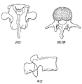
도 1a 및 도 1b는 각각 관심있는 척추 영역의 척추뼈의 측면 및 후면의 3차원 컴퓨터 영상들로서, CT, MRI 또는 다른 연구들에 의해 만들어진 것이다.1A and 1B are three-dimensional computer images of the lateral and back surfaces of the vertebrae of the vertebral region of interest, respectively, made by CT, MRI or other studies.
도 2는 도 1a 및 도 1b에 도시된 척추 영역으로부터 수작업의 달걀껍질 모양의 척추체 제거술이 진행되는 각각의 척추골의 3차원 컴퓨터 영상들을 도시한다.FIG. 2 shows three-dimensional computer images of each vertebra with manual eggshell vertebral body removal from the vertebral region shown in FIGS. 1A and 1B.
도 3은 척추경 내에서 가장 좁은 직경 또는 단면 영역(협부)을 도시하는 속이 제거된 각각의 척추골의 컴퓨터 영상이다.3 is a computerized image of each degenerated vertebra showing the narrowest diameter or cross-sectional area (isthmus) in the pedicle.
도 4는 협부의 중심을 관통하며 후방의 척추경을 통과하여 반대방향을 향하여 전방의 내부 피질로 연장되는 직선의 생성을 나타내는, 속이 제거된 척추골의 컴퓨터 영상이다.4 is a computerized image of a degenerated vertebrae showing the generation of a straight line passing through the center of the isthmus and passing through the posterior pedicle to the opposite inner cortex.
도 5는 방사 방향을 향하여 동심원적인 협부의 중심을 관통하여 연장되는 직선을 만들어 원통을 형성하는 것을 도시하는 개략도이다.FIG. 5 is a schematic diagram illustrating forming a cylinder by making a straight line extending through the center of a concentric concentric portion in the radial direction.
도 6a 및 도 6b는 각각 대칭적이며 비정형적인 형상을 갖는 속이 제거된 각각의 척추골의 개략도이다.6A and 6B are schematic diagrams of each vertebral bone removed, each having a symmetrical and atypical shape.
도 7a 및 도 7b는 직선 척추경과 만곡된 척추경의 협부를 각각 도시하는 개략도들이다.7A and 7B are schematic diagrams respectively illustrating a narrow portion of a straight pedicle and a curved pedicle.
도 8은 척추경 나사의 길이를 결정하기 위한 원통의 길이를 도시하는 속이 제거된 척추골의 개략도이다.8 is a schematic diagram of a hollowed vertebra showing the length of the cylinder for determining the length of the pedicle screw.
도 9는 척추경 나사를 설치하기 위해 의사에 의해 꼬리표가 붙은(labeled) 각각의 척추골의 개략적인 측면 입면도다.FIG. 9 is a schematic side elevation view of each vertebrae labeled by a physician for installing pedicle screws. FIG.
도 10a는 척추경 나사의 최대 직경과 길이, 시상면과 횡단면에 대한 척추경 나사의 궤적 각도의 데이터의 컴퓨터에 의해 생성된 요약표이다.FIG. 10A is a computer generated summary table of data of the maximum diameter and length of pedicle screws, the angle of trajectory of the pedicle screws relative to the sagittal plane and the cross section.
도 10b는 도 10a의 시상면과 궤적 각도들의 성질을 나타내는 척추골의 개략적인 측면도이다.FIG. 10B is a schematic side view of the vertebrae illustrating the properties of the sagittal plane and trajectory angles of FIG. 10A.
도 10c는 도 10a의 횡단면과 궤적 각도들의 성질을 나타내는 척추골의 개략적인 평면도이다.FIG. 10C is a schematic plan view of the vertebrae illustrating the properties of the cross section and trajectory angles of FIG. 10A. FIG.
도 10d는 도 10a의 관상면과 궤적 각도들의 성질을 나타내는 척추골의 개략적인 평면도이다.FIG. 10D is a schematic plan view of the vertebrae illustrating the nature of the coronal plane and trajectory angles of FIG. 10A.
도 11은 관상의 궤적을 나타내는 AP 평면에서 도 10a의 데이터 요약표에서 식별된 이상적인 척추경 나사의 배치들에 대한 컴퓨터에 의해 생성된 개략적인 도 면이다.FIG. 11 is a computer generated schematic view of the ideal pedicle screw placements identified in the data summary table of FIG. 10A in the AP plane representing the coronary trajectory. FIG.
도 12는 도 10a의 요약표의 데이터에 대응되는 최대 가용 나사 크기 변수들의 표와, 척추경 저부 원주 윤곽들(관상면들)과 척추경 간격 지점들(A-B)이다.FIG. 12 is a table of maximum available screw size parameters, pedicle bottom circumferential contours (coronal planes) and pedicle spacing points A-B, corresponding to the data of the summary table of FIG. 10A.
도 13은 도 12의 표에 의해 식별된 나사 배치들의 컴퓨터에 의해 생성된 개략적인 도면이다.FIG. 13 is a schematic diagram generated by a computer of the screw arrangements identified by the table of FIG. 12.
도 14a는 협부와 척추경 저부의 원주를 도시하는 척추골의 개략적인 측면 입면도이다.14A is a schematic side elevation view of the vertebrae showing the circumference of the buccal and pedicle base.
도 14b는 척추경 저부의 원주를 관통하여 연장되는 컴퓨터에 의해 생성된 척추경 원통을 횡단면과 관상면에서 도시하는 척추골의 개략적인 투시도이다.14B is a schematic perspective view of the vertebrae showing a computer generated pedicle cylinder extending through the circumference of the pedicle bottom in cross section and coronal plane.
도 14c, 14d와 14e는 협부와 각각의 척추골에서의 척추경 저부 원주 사이의 관계를 나타내는 요추, 등뼈, 목뼈의 각각 영역에서의 척추골의 투시도이다.14C, 14D and 14E are perspective views of vertebrae in respective regions of the lumbar spine, spine and neck bone showing the relationship between the isthmus and the pedicle bottom circumference in each vertebra.
도 14f와 14g는 척추골 내에 척추경 안내 구멍을 생성시키기 위한 송곳의 배치를 도시하는 척추골의 개략적인 후방 입면도이다.14F and 14G are schematic rear elevational views of the vertebrae showing the placement of the awl for creating pedicle guide holes in the vertebrae.
도 14h는 수작업으로 결정되어 척추경 저부 원주의 중심을 관통하여 연장되는 척추경 나사 안내선을 갖는 척추골의 개략적이며 정렬된 투시 입면도와 후방 입면도를 도시한다.FIG. 14H shows a schematic, aligned perspective elevation and posterior elevation of the vertebrae with pedicle screw guides determined manually and extending through the center of the pedicle base circumference.
도 15a, 15c 및 15e는 척추경 저부 원주를 관통하여 연장되는 컴퓨터에 의해 생성된 척추경 나사 원통을 다른 각도들에서 본 척추골의 개략적인 후방 입면도들을 도시한다.15A, 15C, and 15E show schematic rear elevational views of the vertebrae seen from different angles of a computer generated pedicle screw cylinder extending through the pedicle bottom circumference.
도 15b, 15d 및 15f는 도 15a, 15c 및 15e의 각각에 도시된 척추골의 개략적 인 측면 입면도들을 도시한다.15B, 15D and 15F show schematic side elevational views of the vertebrae shown in each of FIGS. 15A, 15C and 15E.
도 16은 척추경 형태와, 협부와, 수술 중의 각각의 척추골들의 AP 형광투시 영상들과 관련된 척추경 안내공 입구 지점들의 결정을 나타내는 척추경들 T1, T2, T4 및 T5를 관통하는 CT 횡단면 도면들을 도시한다.FIG. 16 is a CT cross-sectional view through pedicles T1, T2, T4 and T5 showing pedicle morphology, isthmus, and pedicle guide entry points associated with AP fluoroscopic images of respective vertebrae during surgery. Show them.
도 17a 및 17b는 본 발명의 조정 가능한 송곳의 다른 변형예들의 측면 입면도들이다.17A and 17B are side elevation views of other variations of the adjustable awl of the present invention.
도 18a는 각각의 척추골 및 척추경 저부의 원주들의 수술 중의 AP 형광투시 영상의 개략적인 도면이다.18A is a schematic diagram of an AP fluoroscopy image during surgery of the circumferences of each vertebra and pedicle bottom.
도 18b는 컴퓨터에 의해 배치된 척추경 원통들과 척추경 저부 원주를 갖는 컴퓨터에 의해 생성된 척추골의 3차원 영상들의 개략도이다.18B is a schematic diagram of three-dimensional images of a vertebral bone generated by a computer having pedicle cylinders arranged by computer and a pedicle bottom circumference.
도 18c는 도 18a 및 18b에 기록된 영상들의 개략도이다.18C is a schematic diagram of the images recorded in FIGS. 18A and 18B.
도 19a는 본 발명에 따라 제작된 이중링 척추경 나사 정렬 장치의 개략적인 측면 입면도이다.19A is a schematic side elevation view of a dual ring pedicle screw alignment device constructed in accordance with the present invention.
도 19b는 도 19a에 도시된 장치의 전방 입면도이다.19B is a front elevation view of the device shown in FIG. 19A.
도 19c 및 19d는 경피적 환경과 외과적으로 개방된 환경에서 이중링 척추경 나사 정렬 장치의 사용을 도시한 척추골의 개략적인 평면도이다.19C and 19D are schematic plan views of the vertebrae illustrating the use of a dual ring pedicle screw alignment device in a percutaneous and surgically open environment.
도 20은 변형된 이중링 척추경 나사 정렬 장치의 전방 입면도이다.20 is a front elevation view of a modified dual ring pedicle screw alignment device.
도 21a 및 도 21b는 도 19a 및 19b에 도시된 이중링 정렬 장치를 위한 천공 캐뉼러(cannula) 부재의 제1 실시예의 단부의 측면 및 전방 입면도들이다.21A and 21B are side and front elevation views of the end of a first embodiment of a perforated cannula member for the dual ring alignment device shown in FIGS. 19A and 19B.
도 22a 및 도 22b는 도 19a 및 19b에 도시된 이중링 정렬 장치를 위한 천공 캐뉼러 부재의 제2 실시예의 단부의 측면 및 전방 입면도들이다.22A and 22B are side and front elevation views of the end of a second embodiment of a perforated cannula member for the dual ring alignment device shown in FIGS. 19A and 19B.
도 23a는 도 19a 및 19b의 이중링 정렬 장치와 함께 사용되기 위한 슬롯이 형성된 외측 캐뉼러의 사시도이다.FIG. 23A is a perspective view of a slotted outer cannula for use with the dual ring alignment device of FIGS. 19A and 19B.
도 23b는 도 23a에 도시된 내측에 배치되는 정렬링을 구비하는 슬롯이 형성된 캐뉼러의 전방 입면도이다.FIG. 23B is a front elevational view of a slotted cannula having an alignment ring disposed inside shown in FIG. 23A.
도 24는 중심에 위치한 또는 이상적인 궤적 내에서의 다른 척추경 나사 궤적들과, 골외의 궤적 또는 중심에 위치한 궤적으로부터 접선방향으로 편심된 임시의 척추경 주변을 통과하는 궤적을 도시하는, 속이 제거된 척추골의 개략도이다.FIG. 24 is a hollowed out trajectory showing other pedicle screw trajectories within a centered or ideal trajectory and around a temporary pedicle periphery tangentially eccentric from the extra-orbital or centrally located trajectory. Schematic diagram of the vertebrae.
도 25는 본 발명의 방법에 따라 척추경 나사를 설치하는 것을 도시하는 척추골의 개략적인 평면도이다.25 is a schematic plan view of the vertebrae illustrating the installation of a pedicle screw in accordance with the method of the present invention.
도 26a, 도 26b 및 도 26c는 각각 척추경 저부 원주 및 협부를 통과하도록 컴퓨터에 의해 생성된 척추경 원통을 도시하는 척추골의 측 입면도, 평면도 및 후방 입면도이다.26A, 26B and 26C are side elevation, top and rear elevations of the vertebrae showing a pedicle cylinder generated by the computer through the pedicle bottom circumference and isthmus, respectively.
도 27a, 도 27b 및 도 27c는, 도 26a, 도 26b 및 도 26c와 각각 유사하며, 골절 및 동반된 비정상적 해부구조를 갖는 척추골에서 편심 배치를 갖도록 컴퓨터에 의해 생성된 척추경 원통을 도시하는 개략도들이다.27A, 27B and 27C are schematic diagrams illustrating computer generated pedicle cylinders similar to FIGS. 26A, 26B and 26C, respectively, with eccentric placement in the vertebrae with fractures and associated abnormal anatomy admit.
도 28a, 도 28b 및 도 28c는, 도 27a, 도 27b 및 도 27c와 각각 유사하며, 척추골에서 수정된 편심 배치를 갖도록 컴퓨터에 의해 생성된 척추경 원통을 도시하는 개략도들이다.28A, 28B and 28C are schematic diagrams showing pedicle cylinders generated by a computer similar to FIGS. 27A, 27B and 27C, respectively, with modified eccentric placement in the vertebrae.
도 29는 척추골 및 본 발명의 방법에 따른 송곳/가이드 와이어를 도시하는 개략 배면 입면도이다.29 is a schematic rear elevational view illustrating the vertebra and the awl / guide wire in accordance with the method of the present invention.
도 30은 도 29와 유사하며, 송곳/가이드 와이어가 척추골에 부분적으로 삽입된 것을 도시하는 개략도이다. FIG. 30 is a schematic view similar to FIG. 29, showing the awl / guide wire partially inserted into the vertebrae.
도 31은 도 29 및 도 30과 각각 유사하며, 송곳/가이드 와이어가 척추골에 전부 삽입된 것을 도시하는 개략도이다.FIG. 31 is similar to FIGS. 29 and 30, respectively, and is a schematic diagram showing that the awl / guide wire is fully inserted into the vertebrae.
도 32는 도 31과 유사하며, 드릴 비트(drill bit)가 가이드 와이어를 통과하여 척추골로 삽입된 것을 도시하는 개략도이다.FIG. 32 is a schematic view similar to FIG. 31, showing a drill bit inserted through the guide wire into the vertebrae.
도 33은 도 31과 유사하며, 제1 캐뉼러(cannula)가 가이드 와이어를 통과하여 척추골로 삽입된 것을 도시하는 개략도이다.FIG. 33 is similar to FIG. 31, showing a schematic diagram showing a first cannula inserted through the guide wire into the vertebrae.
도 34는 도 33과 유사하며, 제1 캐뉼러(cannula)가 척추골에 삽입되고 제2 캐뉼러가 제1 캐뉼러 내에서 삽입되는 것을 도시하는 개략도이다.FIG. 34 is similar to FIG. 33, with a schematic diagram showing a first cannula inserted into the vertebra and a second cannula inserted into the first cannula.
도 35는 도 34와 유사하며, 제2 캐뉼러가 제1 캐뉼러 내에서 삽입되는 것을 도시하는 개략도이다.FIG. 35 is similar to FIG. 34, schematically illustrating the insertion of a second cannula within the first cannula.
도 36은 도 35와 유사하며, 카테터 또는 유사 기구가 제2 및/또는 제1 캐뉼러를 통해 척추골 내부로 삽입되는 것을 도시하는 개략도이다.FIG. 36 is similar to FIG. 35, and is a schematic illustrating insertion of a catheter or similar instrument into the vertebrae through the second and / or first cannula.
도 37은 도 36과 유사하며, 풍선 카테터가 제2 및/또는 제1 캐뉼러를 통해 척추골 내부로 삽입되는 것을 도시하는 개략도이다.FIG. 37 is similar to FIG. 36, schematically illustrating the insertion of a balloon catheter into the vertebrae through the second and / or first cannula.
도 38a 및 도 38b는 제2 캐뉼러를 통해 기울어진 카테터가 척추골에 부분적으로 삽입된 것을 각각 도시하는 평면도 및 배면 입면도이다.38A and 38B are top and rear elevations, respectively, showing the catheter tilted through the second cannula partially inserted into the vertebrae.
도 39a 및 도 39b는 도 38a 및 도 38b와 각각 유사하며, 제2 캐뉼러를 통해 기울어진 카테터가 척추골에 전부 삽입된 것을 도시하는 개략도이다.39A and 39B are similar to FIGS. 38A and 38B, respectively, and are schematic diagrams showing that the catheter tilted through the second cannula is fully inserted into the vertebrae.
본 발명에 따라 척추경 나사의 크기와 배치를 결정하는 방법들이 이하에서 더욱 상세히 기술된다.Methods for determining the size and placement of pedicle screws in accordance with the present invention are described in more detail below.
단계 1
관심있는 척추 영역에서의 컴퓨터 단층촬영(computed tomography scan; CT), 자기 공명 영상(MIR), 단층 가능한 형광투시법 또는 유사한 2차원 영상의 그림이 먼저 얻어진다. 정확도와 상세성을 증대시키기 위해서는 얇은 단면이 바람직하다.Pictures of computed tomography scans (CT), magnetic resonance imaging (MIR), tomographic fluoroscopy or similar two-dimensional images of the spinal region of interest are first obtained. Thin cross sections are preferred to increase accuracy and detail.
단계 2
치수적으로 실제와 동일한(dimensionally true) 척추뼈의 3차원의 컴퓨터 영상이 CT, MRI 또는 다른 연구들이나 다른 적절한 방식에 의해 도 1a 및 도 1b에 도시된 것처럼 만들어진다.Three-dimensional computer images of dimensionally true vertebrae are made as shown in FIGS. 1A and 1B by CT, MRI or other studies or other suitable manner.
단계 3Step 3
도 2에 도시된 것과 같이, 3차원의 각각의 척추골은 그 다음, 달걀껍질 모양의 척추경 통과 척추체 제거술(eggshell transpedicular vertebral corpectomy)과 유사하게, 의사가 원하는 사양에 따라(즉 척추골 몸통 피질 또는 피질벽들에 남아 있는 피질벽의 두께) 컴퓨터에 의해 공동화(hollowed out)된다. 이와 같은 사양들 은 비대칭의 두께들, 예를 들어 전방의 척추골 몸통 피질이 5 mm 의 두께가 될 수 있고, 측방 척추골 몸통벽이 7 mm 의 두께가 될 수 있고, 척추경 벽들이 겨우 1 mm 의 두께가 될 수 있는, 또는 그와 유사한 것을 고려한다. 각각의 척추골은 속이 찬(cored) 또는 속이 빈(hollowed out) 구조로 형상화될 수 있으며, 그 결과 남는 척추골 몸통은 전자화(electrified)되거나 적절한 방식에 의해 그 벽부를 따라 밝게 표시(highlighted)된다.As shown in FIG. 2, each vertebra in three dimensions is then subject to the specifications desired by the doctor (ie, vertebral cortex or cortex), similar to eggshell transpedicular vertebral corpectomy. Thickness of the cortical wall remaining in the walls). Such specifications can be asymmetrical thicknesses, for example, the anterior vertebral cortex can be 5 mm thick, the lateral vertebral torso wall can be 7 mm thick, and the pedicle walls only 1 mm. Consider what may be the thickness, or the like. Each vertebra can be shaped into a cored or hollowed out structure, with the result that the remaining vertebral torso is electrified or highlighted along its wall in an appropriate manner.
단계 4Step 4
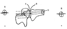
그리고 컴퓨터는, 도 3에 도시된 바와 같이, 의사가 선택한 척추경 피질벽의 직경에 기초한 어떤 척추경 내에서 가장 좁은 직경 또는 단면 영역(협부 또는 isthmus)(X)를 결정함으로써 배치될 나사의 허용 가능한 최대 직경을 자동적으로 결정한다.And the computer allows the screw to be placed by determining the narrowest diameter or cross-sectional area (isthmus or isthmus) X in any pedicle based on the diameter of the pedicle cortical wall selected by the physician, as shown in FIG. Automatic determination of the maximum possible diameter.
단계 5
그리고 컴퓨터는 이상적인 축/궤적을 결정하는 도 4에 도시된 직선(10)으로서 협부의 중심에서 시작하여 반대되는 방향으로, 예를 들어 척추경의 협부의 평면에 수직한 방향으로 연장됨으로써 협부의 중심이 지레 받침(fulcrum)이 되어 나머지 피질과 접촉하지 않으며 가능한 한 척추경 내에 동심원적으로 배치되는 연장된 원통을 형성한다. 이 직선은 등쪽 또는 후방의 척추경 피질을 관통함으로써 환자의 피부를 지나 약간의 원하는 길이에까지 연장될 수 있도록 허용된다. 직선은 의사에 의해 선택된 미리 정해진 후방의 내부 피질벽으로부터 미리 정해진 간격(예를 들어 5 mm) 내에 이르는 범위에서 척추골 몸통 내에서 끝난다. 그리하여 직선은 후방의 외부 피질을 관통하지 않으며, 후술하는 바와 같이 나사 직경을 최대화한다.And the computer is a
단계 6Step 6
그리고 컴퓨터는, 도 5에 개략적으로 도시된 바와 같이, 직선(10)을 방사 방향으로 동심원적으로 확장하여 최종 최대 직경(final maximum diameter)까지 이르게 할 수 있다. 직선의 최종적인 최대 직경은 의사가 선호하는 척추경 피질벽 두께에 기초하여 형성되는 가장 좁은 척추경 직경을 초과하지 않을 것이다. 이와 같은 동심원적인 형성은 궁극적으로는 눈에 보이는 원통(12)으로 성장하여, 원통의 외측면의 어떤 지점이 밝게 표시된 내부 피질벽과 접촉할 때 성장이 멈춘다. 형성된 원통은 중심에 동심원적으로 형성되며 원통(12)에 비해 다른 색이나 무늬로 식별될 수 있는 시작 직선(beginning line)(10)을 갖는다. 후술하는 바와 같이 원통(12)은 후술하는 자동화된 방법들의 어느 하나에 따라 나사들을 배치하는 것을 용이하게 하기 위하여 등쪽 피질/후방 피질과의 교차점을 넘어서 연장될 수 있다.The computer can then extend the
단계 7Step 7
도 6b에 도시된 것과 같은 비정형적인 해부 형태를 갖는 척추경들(pedicles which have irregular anatomy)이나 만곡된 척추경들(curved pedicles)(도 7b) 또는 유사한 기형을 갖는 척추경들에 대하여 허용된 최대의 직경은 사실상 최소 직경 방법(narrowest diameter method)에 의해 결정된 직경보다 작을 수도 있다. 이로 인해 피질 척추경 벽의 갈라짐이 방지된다.Maximum allowed for pedicles which have irregular anatomy or curved pedicles (FIG. 7B) or similar malformations, as shown in FIG. 6B. The diameter of may in fact be smaller than the diameter determined by the narrowest diameter method. This prevents the splitting of the cortical pedicle wall.
단계 8Step 8
컴퓨터는 그 이후에 미리 정해진 후방의 내부 피질 근처의 도 8의 지점(D)에서 시작하여 등쪽 피질/후방 피질과의 교차점에까지 이르는 원통(12)의 길이를 측정함으로써 나사의 길이를 결정한다.The computer then determines the length of the screw by measuring the length of the
단계 9
컴퓨터는 그 이후에 각각의 개별적인 척추경을 위한 이상적인 척추경 나사 직경과, 길이와, 궤적(도 10b 및 10c에 도시된 것과 같이 기준면으로서 대응되는 상위의 단부 플레이트(20)를 갖는 횡단면과 시상단면에 대하여 각도로 측정됨)을 나타내는 도 10a에 도시된 것과 같은 데이터 요약표를 제공한다. 개별적인 척추골은 의사로 하여금 도 9에 도시된 바와 같이 어떤 특정 척추골을 식별(identify)하게 함으로써 꼬리표가 붙여지며, 그 이후에 의사가 정확한 척추골 몸통의 꼬리표를 확인함으로써 컴퓨터가 나머지 척추골 몸통들에 자동적으로 꼬리표를 붙인다.The computer then has an ideal pedicle screw diameter for each individual pedicle, a length, and a cross section and sagittal section with the
단계 10
이와 같이 표로 나타낸 데이터는 이 시점에서 도 12에 도시된 바와 같이 최대의 척추경 나사 지름과 길이에 기초하여 척추경 나사를 이용하는 실행 가능성을 결정하기 위해 이용될 수 있으며, 의사가 선호하는 방법에 의한 나사의 배치를 위해서도 이용될 수 있다. 또한 도 12는 A에서 B 지점에 이르는 각각의 척추경 저부 원주 윤곽들(pedicle base circumference outlines)(관상 궤적(coronal trajectory))과 척추경의 각각의 길이들을 제공한다. 실제 이용되는 나사의 크기들은 상업적으로 이용할 수 있는 나사들에 대한 의사의 선택에 기초될 것이다. 일단 의사가 선택된 척추경 나사 시스템에서 이용 가능한 나사 크기의 범위를 제공한다면, 컴퓨터는 자동적으로 이 표를 결정하여 생성할 수 있고, 부수적으로는 도 13에 도시된 데이터에 의해 이상화된 개략적인 AP(관상), 측면 및 횡단면 도면들을 형성할 수 있다. 나아가 이와 같은 시스템은 의사에게 개벽적인 척추골을 기초로 한 최대 허용 가능한 직경과는 다른 직경을 선택할 수 있는 부수적 능력을 제공하고, 이와 같은 부수적인 변형들을 요약 데이터와 도식들에 병합한다.This tabular data can be used at this point to determine the feasibility of using pedicle screws based on the maximum pedicle screw diameter and length, as shown in FIG. It can also be used for placement of screws. 12 also provides respective pedicle base circumference outlines (coronal trajectory) and respective lengths of the pedicle from A to B points. The actual screw sizes used will be based on the physician's choice of commercially available screws. Once the physician has provided a range of screw sizes available for the selected pedicle screw system, the computer can automatically determine and generate this table, and, incidentally, the approximate AP (idealized by the data shown in FIG. 13). Tubular), lateral and cross-sectional views. Furthermore, such a system provides the physician with the ability to select a diameter other than the maximum allowable diameter based on the open vertebrae and incorporates these additional variations into summary data and schemes.
단계 11 - 수동 척추경 나사 배치(Manual Pedicle Screw Placement)Step 11-Manual Pedicle Screw Placement
의사는 그 이후에 의사의 선호하는 방법에 기초하여 척추경 나사를 배치하기 위해 이상화된 개략적인 도해와 요약 데이터를 이용할 수 있다.The surgeon can then use the idealized schematic illustration and summary data to place the pedicle screw based on the physician's preferred method.
단계 12a - 척추경 저부 원주 윤곽 방법 - 수동 결정(Pedicle Base Circumference Outline Method - Manual Determination)Step 12a-Pedicle Base Circumference Outline Method-Manual Determination
이 방법은 이상적인 척추경 나사 궤적을 도 10d 및 도 11에 도시된 관상면(coronal plane)에서 일치시키기 위하여 X선 촬영 척추골 몸통의 해부적 경계표 들을 이용한다. 구체적으로, 표준적인 앞뒤방향 X선 또는 형광투시 영상들(fluoroscopic images)에서 보이는 방사선 밀도 원형 선들은 척추경 저면 원주(pedicle base circumference)들과 일치한다. 척추경 저면 원주 B는 척추경 벽과 척추경 벽의 척추골 몸통에 대한 전이부(transition)의 사이의 피질 교차부(cortical junction)로 형성된다. 이 척추경 저부 원주는 척추경 협부와 명확히 다르다. 그러나 어떤 경우에는 일체가 되어 동일하거나 도 14a 내지 14e에 도시된 바와 같은 각각의 척추에 겹쳐질 수 있다.This method uses anatomical landmarks of the x-ray vertebral body to match the ideal pedicle screw trajectory in the coronal plane shown in FIGS. 10D and 11. Specifically, the radiation density circular lines seen in standard anterior x-ray or fluoroscopic images coincide with the pedicle base circumferences. The pedicle base circumference B is formed of a cortical junction between the pedicle wall and the transition to the vertebral torso of the pedicle wall. This pedicle base circumference is distinctly different from the pedicle isthmus. In some cases, however, they may be integral and overlap the respective vertebrae, either identical or as shown in FIGS. 14A-14E.
척추경 저부 원주 기술의 수동 이용을 위해서는, 먼저 척추경 협부 X를 관통하는 이상적인 궤적이 도 14b에 도시된 것과 같은 척추경을 통과하는 횡단면의 대응되는 X선촬영 영상을 사용하여 수동으로 결정되어야 한다. 그 이후에 최대 직경 척추경 나사를 결정하기 위해서 척추경 협부(X)가 측정된다. 최대 척추경 나사 길이의 결정을 위하여 궤적이 이용된다. 그리고 척추경 저부 원주(B)는 도 14b에 도시된 것과 같이 척추경 벽의 척추골 몸통으로의 전이부(transition)를 식별함으로써 결정된다. 최종적으로 후방 피질(A) 상의 시작점에서 척추경 저부 원주(B)와의 교차점에 이르는 길이(A-B)가 측정되어, 후술하는 길이가 가변되는 송곳과 같이 적절한 공구의 조정을 위해 사용된다. 지점 A와 지점 B는 도 14h에 도시된 바와 같이 척추경 저부 원주의 상측(머리쪽(cephalad)) 가장자리와 바닥(꼬리쪽(caudad)) 가장자리로부터 저부 원주에 대해 중심이 맞추어져야 한다. 그 이후에 지점 A가 척추경 저부 원주의 앞뒤방향 돌출에 대하여 위치하는 곳과 지점 B가 척추경 저부 원주 내에 위치하는 곳을 결정하기 위해 척추경 저부 원주의 이상적인 궤적과 척추경 저 부 원주가 병합된다. 이 척추경 저부 원주 윤곽은 각각의 척추골을 위한 앞뒤방향의 X선촬영 영상(radiographic image)을 닮은 원형의 형상(circular configuration)을 가질 것이다.For manual use of the pedicle bottom column technique, the ideal trajectory through the pedicle narrow X must first be manually determined using the corresponding X-ray image of the cross section through the pedicle, as shown in FIG. 14B. . The pedicle narrow X is then measured to determine the maximum diameter pedicle screw. The trajectory is used to determine the maximum pedicle screw length. And the pedicle bottom circumference B is determined by identifying the transition of the pedicle wall to the vertebral body, as shown in FIG. 14B. Finally, the length A-B from the starting point on the posterior cortex A to the intersection with the pedicle bottom circumference B is measured and used for the adjustment of the appropriate tool, such as an auger of varying length described below. Points A and B must be centered relative to the bottom circumference from the top (cephalad) edge and bottom (caudad) edge of the pedicle bottom circumference, as shown in FIG. 14H. The ideal trajectory of the pedicle base circumference and the pedicle base circumference are then merged to determine where point A is located with respect to the anterior and posterior protrusions of the pedicle base circumference and where point B is located within the pedicle base circumference. do. This pedicle bottom circumferential contour will have a circular configuration that resembles a front and back X-ray radiographic image for each vertebra.
척추경 나사들의 수동 배치를 위하여, 각각의 척추골 몸통의 상위의 단부 플레이트를 형광투시 영상에 평행하게 정렬하기 위해 표준적인 형광투시 장치(standard fluoroscopy unit)가 사용될 수 있다. 나아가, 그 상위 단부 플레이트가 대칭인 디스크 공간(disc space)에 의해 형광투시적으로 형상화되었을 때, 그리고 형광투시 AP 영상 위에서 시각적으로 일치하는 척추경 저부 원주 윤곽들을 구비함으로써 척추골 몸통이 각각의 척추경으로부터 등거리에 있을 때, 척추골 몸통이 머리쪽의 척추골 몸통에 대해 중심이 맞추어진다. 이와 같은 중심 맞추기는, 선천성 기형(congenital anomalies), 종양(tumors), 골절(fractures)과 같이 척추골 몸통마다 두 개의 척추경들 이외의 것이 있을 때 여전히 발생할 수 있다. 그 이후에 적절히 조정된 가변 길이의 송곳이나 다른 적절한 공구(T)가 대응되는 척추골 몸통의 후방 피질의 형광투시 영상 하에서 척추경 안내 시작 구멍 지점 A에 배치되고, 도 14f 및 14g에 도시된 바와 같이, 지점 B에까지 전진한다. 이와 같은 배치는 형광투시적으로 확인되며 이상적인 궤적과 일치하는 직선상에서의 두 개의 지점들(A, B)을 나타낸다. 공구(T)는 연장하기 위해 재조정될 수 있고, 척추골 몸통 내로 지점(D)까지 더욱 전진하거나 다른 척추경 탐침 송곳이나 유사한 공구로 교체된다. 그리고 척추경은 뼈속 안전성(intraosseous integrity)을 위해 조사되고, 탭핑 가공된 구멍과 적절한 직경과 길이의 척추경 나사가 척추골 몸통 내에서 척추경을 통 과하며 배치된다.For manual placement of the pedicle screws, a standard fluoroscopy unit can be used to align the upper end plate of each vertebral body parallel to the fluoroscopic image. Furthermore, the vertebral torso can be defined in each pedicle by its upper end plate being fluoroscopically shaped by symmetrical disc space and by having visually consistent pedicle bottom circumferential contours on the fluoroscopic AP image. When equidistant from, the vertebral body is centered relative to the vertebral body on the head side. Such centering can still occur when there is something other than two pedicles per vertebral body, such as congenital anomalies, tumors, and fractures. An appropriately adjusted variable length auger or other suitable tool T is then placed at the pedicle guide start hole point A under the fluoroscopy image of the posterior cortex of the corresponding vertebral body, as shown in FIGS. 14F and 14G. Advance to point B. This arrangement is fluoroscopically identified and represents two points A and B on a straight line consistent with the ideal trajectory. The tool T may be readjusted to extend and further advanced into the vertebral trunk to point D or replaced with another pedicle probe awl or similar tool. The pedicle is then examined for intraosseous integrity and tapped holes and pedicle screws of appropriate diameter and length are placed through the pedicle within the vertebral body.
단계 12a에 따르면, 도 16에 도시된 바와 같이 척추경 T1, T2, T4, T4를 관통하는 CT 횡단면은 척추경 형태와, 협부와, 각각의 척추골의 수술 중의 AP 형광투시 영상들과 관련 있는 척추경 안내 구멍의 입구 지점들의 수동 결정을 나타낸다. 척추경 나사 길이와, 직경과, 궤적은 이미 결정된다. 척추경 저부 원주 윤곽은 바닥 오른쪽 구석에 원으로 표시되었고, 척추경 안내 구멍 시작점으로 식별하기 위한 수술 중의 표시(intraoperative marker)로 사용된다. 예를 들어 T1 및 T2의 척추경들을 위한 시작점 A는 각각 대략 2의 척추경 저부 원주들과 1.25 척추경 저부 원주들이다. (원내에서 점으로 표시되었다). T4 및 T5의 척추경 안내 구멍들은 각각 0.9 및 0.8 척추경 저부 원주들이다.According to step 12a, the CT cross section through the pedicles T1, T2, T4, and T4, as shown in FIG. 16, is associated with the pedicle shape, the isthmus, and the spine associated with the AP fluoroscopy images of the vertebrae during surgery. Represents the manual determination of the inlet points of the radial guide hole. Pedicle screw length, diameter, and trajectory have already been determined. The pedicle circumferential contour is circled in the bottom right corner and used as an intraoperative marker to identify the pedicle guide hole starting point. For example, the starting point A for the pedicles of T1 and T2 are approximately 2 pedicle base circumferences and 1.25 pedicle base circumferences. (Indicated by a dot in the circle). The pedicle guide holes in T4 and T5 are 0.9 and 0.8 pedicle bottom circumferences, respectively.
단계 12b - 척추경 저부 원주 윤곽 방법 - 반자동(Pedicle Base Circumference Outline Method -Semi-Automated)Step 12b-Pedicle Base Circumference Outline Method-Semi-Automated
이 방법은 컴퓨터에 의해 생성된 척추경 원통들이 동심원적으로 만들어진 이후에 지점들 A 및 B와 척추경 저부 원주 윤곽이 컴퓨터에 의해 정해지는 점을 제외하고는 단계 12a와 유사하다. 이 데이터는 도 12와 같이 요약된다. 또한 데이터는 상위의 단부 플레이트와 중간의 척추골 몸통에 대하여 각도로 측정된 시상(sagittal), 횡단면 궤적 각도들(transverse trajectory angles)을 포함한다. 가변 길이의 송곳 또는 다른 공구는 예를 들어 도 12에 요약된 특정 척추경 길이 A-B와, 단계 12a에 기술된 표준적인 형광투시법에 의해 배치된 나사들에 맞추어 적절 하게 조절될 수 있다.The method is similar to step 12a except that points A and B and the pedicle bottom circumferential contour are defined by the computer after the computer-generated pedicle cylinders are made concentrically. This data is summarized as in FIG. The data also includes sagittal, transverse trajectory angles measured in degrees with respect to the upper end plate and the medial vertebral torso. The variable length awl or other tool can be appropriately adjusted to the screws placed by, for example, the particular pedicle length A-B summarized in FIG. 12 and the standard fluoroscopy described in step 12a.
단계 12c - 척추경 저부 원주 윤곽 방법 - 완전 자동(Pedicle Base Circumference Outline Method - Fully' Automated)Step 12c-Pedicle Base Circumference Outline Method-Fully 'Automated
이 방법은 척추경 나사의 배치를 위해 현재의 기술을 확장하여 실시간 영상과 복수 개의 척추골 몸통 형상화를 고려한다. 생성된 데이터는 척추경 저부 원주 윤곽들과 식별된 지점들(A, B)이 동적이어서 척추골 몸통이 중심이 맞추어지거나 상위의 단부 플레이트가 단계 12a 및 단계 12b에서와 같이 형광투시 영상에 평행하게 될 필요가 없는 점을 제외하고는 도 12와 동일하다. 형광투시적으로 촬영된 척추골 몸통들은 어떤 적절한 방법에 의해 컴퓨터에 의해 생성된 대응되는 척추경 원통들을 구비하며 컴퓨터에 의해 생성된 척추골 몸통들로 기록된다. 그리고 지점들 A 및 B는 도 15a, 15c 및 15e에 도시된 바와 같이 형상화되며, 도 12에서와 같이 갱신된 실시간 영상으로 표시된다. 가변 길이의 송곳 또는 다른 공구는 예를 들어 각각의 척추골에 대해 지점 A에서 시작하여 지점 B로 전진하기 위해 적절한 길이로 조정될 수 있다. 본 발명의 방법에 따르면 길이 조정 가능한 송곳 대신 길이 조정이 불가능한 송곳과 같이 어떤 적절한 공구가 사용될 수 있음도 주목하여야 한다.This method extends current techniques for the placement of pedicle screws, taking into account real-time images and plural vertebral body shaping. The data generated is such that the pedicle circumferential contours and the identified points (A, B) are dynamic such that the vertebral torso is centered or the upper end plate is parallel to the fluoroscopic image as in steps 12a and 12b. Same as FIG. 12 except that it is not necessary. The fluoroscopically photographed vertebral bodies are recorded with computer generated vertebral bodies with corresponding pedicle cylinders generated by the computer by any suitable method. The points A and B are shaped as shown in Figs. 15A, 15C and 15E, and are displayed in the updated real time image as shown in Fig. 12. A variable length awl or other tool can be adjusted to an appropriate length, for example, starting at point A and advancing to point B for each vertebra. It should also be noted that in accordance with the method of the present invention any suitable tool may be used, such as a non-length adjustable auger, instead of a length adjustable auger.
단계 13 - 조정 가능한 가변 길이 송곳(Adjustable Variable Length Awl)Step 13-Adjustable Variable Length Awl
지점 A에서 지점 B에 이르는 간격(도 14b)인, 척추경 저부 원주와 교차하는 후방 피질이, 본 발명에 따라 제작된 조정 가능한 가변 길이의 송곳 상에서의 길이 A-B를 설정하기 위해 이용된다. 이 송곳은 형광투시 영상 하에서 척추경 안내 구멍을 설정하기 위해 사용된다. 척추경 안내 구멍은 척추경 나사를 실제로 배치하기 위한 일련의 단계들에서 제1 단계를 형성한다. 척추경 안내 구멍은 컴퓨터에 의해 표시되는 식별된 시작 지점 A에서 시작되어, 일단 안내 구멍이 완전히 안착되면 지점 B로 전진된다.The posterior cortex, intersecting the pedicle bottom circumference, the distance from point A to point B (FIG. 14B), is used to set the length A-B on the adjustable variable length awl made in accordance with the present invention. This awl is used to establish pedicle guide holes under fluoroscopy images. The pedicle guide hole forms the first step in a series of steps for actually placing the pedicle screw. The pedicle guide hole begins at the identified starting point A indicated by the computer and advances to point B once the guide hole is fully seated.
도 17a를 참조하면, 송곳(100)은 방사선 불투과성(radio opaque)의 송곳 부재(104)를 이동 가능하게 지지하는 개방 단부(open end)를 구비하는 방사선 투과성(radiolucent)의 캐뉼러가 형성되는 하우징(102)을 구비한다. 송곳(100)은 길이 A-B에 대응되도록 길이를 가변시키기 위해 완전히 조정 가능하며, 도 14b와 다른 도면들에 도시된 어떤 간격 A-B보다도 송곳이 더 전진하는 것을 방지하도록 형성된다.Referring to FIG. 17A, the
일단 간격 A-B가 X선 촬영법적으로 확정되면, 의사는 지점 A로부터 지점 D에 이르는 길이, 도 14b의 최종 나사 길이로 송곳을 조정할 수 있다. 송곳(100)은 바람직하게는 나무망치 등으로 충격이 가해지는 것을 견딜 수 있는 구성으로 이루어지며 피부를 관통하여 이용되기에 충분할 정도로 좁은 직경으로 이루어진다. 깊이의 형상화(visualization)를 용이하게 하기 위하여 송곳 부재(104)는 색으로 또는 다른 방법에 의해 5 mm 또는 10 mm와 같이 고정된 증가량으로 표시될 수 있다.Once the spacing A-B is confirmed by X-ray imaging, the surgeon can adjust the awl to the length from point A to point D, the final screw length of FIG. 14B. The
송곳(100)은 외측 단부에 타격을 위한 견고한 머리부(108)와, 송곳 부재(104)를 하우징(102)에 대해 원하는 위치에 고정하기 위한 잠금 나사 기구와 같은 적절한 잠금 기구(110)를 구비할 수 있다. 또한 송곳은 송곳 부재(104)의 위치 나 길이를 표시하기 위한 창문(112)이나 다른 표시부를 구비할 수 있다. 도 14f 및 도 14g는 나사 안내 구멍을 형성하기 위해 척추경내로 전진된 송곳을 도시한다.The
도 17b는 캐뉼러가 형성되거나 또는 중공의 송곳 부재(304)와, 중앙 구멍(309)을 구비하는 헤드부(308)를 구비하는 개량된 조정 가능한 송곳(300)을 도시한다. 안내 와이어(311)는 헤드부를 관통하여 연장되며, 송곳 부재(304)를 관통하여 송곳 부재의 단부에까지 이를 수 있다. 안내 구멍이 송곳(300)에 의해 형성된 이후에, 안내 와이어(311)는 척추경 나사를 설치하기 위한 그 후의 단계들이 이루어지는 동안에 안내 와이어의 위치 결정을 위해 안내 구멍에 위치된 상태로 남겨질 수 있다.FIG. 17B shows an improved
단계 14 - 이중링 일치화 기술(Dual Ring Co- Aligned Technique)Step 14-Dual Ring Co-Aligned Technique
수술 중의 척추경 나사의 자동화된 배치를 위해, 컴퓨터에 의해 자동화되어 길이와 직경과 궤적을 형성하는 척추경 나사 원통들을 구비하는 치수적으로 실제와 동일한 3차원 척추 모델이 이용될 수 있다. 부가적으로 수술 중의 영상의 기록을 용이하게 하기 위해 척추경 저부 원주 윤곽 데이터(pedicle base circumference outline data)가 이용된다.For automated placement of pedicle screws during surgery, a dimensionally realistic three-dimensional spine model with pedicle screw cylinders that are automated by the computer to form length, diameter and trajectory can be used. Additionally, pedicle base circumference outline data is used to facilitate the recording of images during surgery.
각각의 척추골을 기초로 한 3차원 모델을 정확하게 기록하기 위해 실시간의 수술 중의 형광투시(fluoroscopy)가 사용된다. 이와 같은 형광투시 척추골 몸통 영상은 화면 상에 중심이 맞추어지고, 특정 척추골 몸통 식별자(vertebral body identifier)(예를 들어 T2, T3 등)를 위해 의사에 의해 식별된다. 대응되는 각각의 치수적으로 실제와 동일한 3차원 척추뼈 모델은 도 18a, 18b 및 18c에 개략적으로 도시된 것과 같이 이 형광투시 영상에 기록된다. 이 과정은 외과적으로 노출된 척추에 대해 수행되거나 피부를 통해서(percutaneously) 수행될 수 있다.Real-time surgical fluoroscopy is used to accurately record three-dimensional models based on each vertebra. Such fluoroscopic vertebral torso images are centered on the screen and identified by a physician for specific vertebral body identifiers (eg, T2, T3, etc.). Each corresponding dimensionally realistic three-dimensional vertebral model is recorded in this fluoroscopy image as schematically shown in FIGS. 18A, 18B and 18C. This process may be performed on surgically exposed vertebrae or percutaneously.
기록은 내부 척추골 몸통의 뼈 표시부들(bony landmarks)을 이용함으로써 발생한다. 이들 표시부들은 척추골 몸통에 연결되는 척추경 피질벽들의 합류부(confluence)로부터 발생하는 형광투시 영상에서 보이는 척추경 저부 원주들이다. 상술한 바와 같이, 이들 척추경 저부 원주들은 형광투시 영상에 대한 척추골 몸통의 회전에 기초하여 형상과 정사각형 영역(square area)을 변경시킬 수 있는 원형 형상이나 타원형 형상(elliptical shapes)을 형성한다.Recording occurs by using bony landmarks of the internal vertebral body. These markers are pedicle bottom circumferences seen in fluoroscopic images resulting from the confluence of pedicle cortical walls connected to the vertebral body. As noted above, these pedicle bottom circumferences form circular or elliptical shapes that can alter shape and square area based on rotation of the vertebral torso with respect to the fluoroscopic image.
그 이후에 수술 중의 형광투시 및 컴퓨터 척추에 의해 형성된 척추경 저부 원주 윤곽들이 기록된다. 윤곽들이 겹쳐지도록 하고 측정된 정사각형 영역들이 동일하도록 하고, 척추경들 사이의 간격이 동일하게 되도록 함으로써 정확한 기록을 얻을 수 있다. 이와 같은 기록 방법은 환자의 뼈대에 고정되는 방사선 표시(radiographic marker)를 할 필요가 없게 만든다. 방사선 표시는 피부를 경유하여 수행되는 시술에 대해서는 특별히 불리함을 갖는다. 이와 같은 방법은 또한 하나의 척추골 몸통의 다른 척추골 몸통에 대한 자유로운 운동(free independent movement)을 가능하게 한다. 이는 컴퓨터에 의해 생성된 모델의 순응도(compliance)를 나타내는 것으로, 불안정한 척추에 있어서 특별히 편리하다. 의사는 나사의 배치를 계속하기 위해 수술 중의 척추경 저부의 원주들의 기록의 적절성(adequacy)을 확인한다. 이 방법은 수술 중의 형광투시 영상에 맞추기 위해 컴퓨 터에 의해 생성된 모델의 확대나 또는 축소를 고려한다.Subsequently, pedicle circumferential circumferential contours formed by fluoroscopy and computer vertebrae during surgery are recorded. Accurate records can be obtained by allowing the contours to overlap, the measured square areas to be the same, and the spacing between the pedicles to be the same. This method of recording eliminates the need for a radiographic marker to be fixed to the patient's skeleton. Radiation marking is particularly disadvantageous for procedures performed via the skin. This method also allows free independent movement of one vertebral body with respect to the other vertebral body. This represents the compliance of the computer generated model, which is particularly convenient for unstable vertebrae. The surgeon confirms the adequacy of the records of the circumferences of the pedicle base during surgery to continue the placement of the screws. This method considers the enlargement or reduction of the model generated by the computer to fit the fluoroscopic images during surgery.
이제 컴퓨터에 의해 생성된 척추경 저부 원주와 척추경 원통을 포함하는 완전한 3차원 영상이 수술 중의 형광투시 영상 위에 겹쳐진다. 그리고 도 19a 및 19b에 도시된 바와 같이 컴퓨터 척추경 원통(200)이 후방의 피질을 관통하여 환자의 신체로부터 돌출되고, 두 개의 독립되고 동일선 상의 링들(202, 204)에 의해 차단된다. 링들은 환자의 침상이나 다른 지지부(미도시)에 고정된 적절한 지지 프레임(206) 상에 장착되며, 컴퓨터 원통 영상의 차단을 허용할 수 있는 크기로 이루어지며, 천공 캐뉼러(drilling cannulas)를 배치할 수 있는 크기로 이루어진다. 제1 링(202)은 후방의 피질 영역(208) 또는 신체 바로 외측에서 컴퓨터 척추경 나사 원통을 차단한다. 그리고 제2 링(204)은 제1 링(202)으로부터 소정 간격 이격되어 컴퓨터 척추경 나사 원통을 차단한다. 두 개의 링들 사이의 간격이 커질수록 나사 배치의 정확도(accuracy)는 더 좋아진다. 링들(202, 204)에 의한 컴퓨터 척추경 실린더의 차단이 컴퓨터 척추경 원통(200)에 대한 링들의 이동을 표시하는 컴퓨터 화면 상에 표시된다.Now a complete three-dimensional image, including a computer generated pedicle bottom cylinder and a pedicle cylinder, is superimposed on the fluoroscopic image during surgery. 19A and 19B, the
도 19c 및 19d는 링들(202, 204)을 관통하여 외과적으로 개방된 환경(surgically open environment)과 피부를 관통하는 환경(percutaneous environment)에서 링들(202, 204)을 관통하여 척추골 몸통(VB)으로부터 돌출하는 컴퓨터에 의해 생성된 원통(200)과, 직선(21)을 각각 도시한다.19C and 19D show the vertebral torso VB through the
척추경 실린더들의 차단(Interception)은 두 개의 단계들로 발생한다. 컴퓨터 척추경 원통들(200)은 둘러싸는 원통을 구비하는 중심 직선(210)으로 구성된다. 첫째로, 링들(202, 204)은 중심 직선(210)과 척추경 원통(200)의 모두에 대해 중심이 맞추어져야 한다. 둘째로, 링들이 척추골 몸통에 기록됨으로써 LED 장치들을 통해 컴퓨터 화면 상에서 링들의 이동이 표시(followed)될 수 있다. 셋째로, 링들은 내부 직경들이 컴퓨터에 의해 생성되는 척추경 실린더들(200)의 대응되는 직경에 맞추도록 제작된다. 다른 직경들을 갖는 다양한 이동 가능한 링들이 제공되어 의사가 요구하는 어떤 척추경 나사 시스템도 이용할 수 있도록 한다. 넷째로, 링들은 도 2에 도시된 것과 같이 컴퓨터에 의해 생성된 척추경 원통의 직경에 대응되는 직경의 일치가 가능하도록 가변되는 직경을 고려하는 적절한 방식으로 조정 가능하게 제작될 수 있다. 링(202)은 직경을 변화시키도록 회전될 수 있는 이동 가능하게 연결된 부분들(212)로 형성된다. 컴퓨터 척추경 원통을 갖는 링들의 기록은 컴퓨터 화면 상에 식별되고 확인된다. Interception of pedicle cylinders occurs in two steps.
두 개의 일치하는 링들(202, 204)은 이제 천공 캐뉼러(214)(도 21a, 21b)를 배치하기 위한 통로(conduit)를 형성한다. 캐뉼러는 또한 환자의 침상이나 다른 지지부에 고정된 프레임(206)에 고정된다. 천공 캐뉼러(214)의 내부에는 단단한 캐뉼러 부재(216, 도 21a, 21b)가 배치되거나, 복수 개의 좁고 이동 가능한 길이 방향의 금속 평행 핀들(metal parallel pins)(220)을 내부에 구비하며 천공배치(drill placement)를 위해 중심이 개방되는 특수한 내부 캐뉼러 부재(218, 도 22a, 22b)가 사용될 수 있다. 복수 개의 핀들(220)은 내부 캐뉼러 부재(218)가 평평하지 않은 면에서도 평평하게 놓이도록 한다. 이와 같은 특성은 천공 비트의 움직임을 방지하도록 후방의 피질 천공 영역에서 부가적인 안정성을 제공한다. The two matching rings 202, 204 now form a conduit for placing the perforated cannula 214 (FIGS. 21A, 21B). The cannula is also secured to the
부가적으로 특수한 내부 캐뉼러 부재(218)는, 척추경 내에서의 천공의 형광투시 영상화를 허용할 수 있도록 복수 개의 평행 핀들이 후퇴되도록 한다. 의사에 의해 어떤 방법도 사용될 수 있다.In addition, a special
그 이후에 척추경은 미리 정해진 척추경 나사 길이를 초과하지 않는 소정의 미리 조정된 깊이로 천공된다. 척추경은 뼈의 안전성을 확보하기 위해 척추경 탐침(pedicle probe)에 의해 조사된다.Thereafter, the pedicle is drilled to a predetermined predetermined depth that does not exceed a predetermined pedicle screw length. The pedicle is irradiated with a pedicle probe to ensure bone safety.
나사를 실제로 배치하기 위해서 슬롯이 형성된 특수한 외측 캐뉼러(도 23a, 23b)가 동일한 선상에 배치되며, 지지 프레임(support frame)이 이동 가능하게 장착되는 서로 정렬된 두 개의 링들(202, 204) 위에 배치된다. 이와 같이 특수한 캐뉼러(230)는 또한 지지 프레임이나 다른 고정 장치에 고정된다. 그리고 링들을 대략 90도(미도시됨) 회전시킴으로써 링들을 제거할 수 있고, 캐뉼러(230)로부터 링들을 빼낼 수 있다. 슬롯이 형성된 캐뉼러의 조정 가능한 내부 직경은 나사면이 형성된 어떠한 척추경 나사 직경과 가변적인 헤드 크기(head size)를 수용하기에 충분하다. 적절한 척추경 나사(미도시됨)는 나사를 유지하는 스크류 드라이버(screwdriver)에 배치되며 슬롯이 형성된 캐뉼러 내에 배치되고, 그 이후에 각각의 척추경 내에 배치된다.A special outer cannula with slots (Figs. 23A, 23B) is arranged on the same line for the actual placement of the screws, and on two mutually aligned
도 20에 도시된 변형된 조정 가능한 정렬된 링들을 위해서, 도 23a의 슬롯이 형성된 캐뉼러(230)가 사용될 수 있으며, 또는 선택적으로 링들(202, 204)이 위치에 유지되어 링들 내에 배치되며 링들을 관통하는 스크류 드라이버를 수용하기 위해 완전히 개방된 위치(fully open position)로 조정될 수 있다.For the modified adjustable aligned rings shown in FIG. 20, the slotted
단계 15
수술 중의 형광투시 영상들을 수술 전의 환자의 척추의 3차원 영상들과 함께 수술 중에 기록하는 기능을 갖는 상업적으로 이용할 수 있는 소프트웨어 패키지가 현재 존재한다. 이와 같은 기능은 요약 수치 데이터(summary numerical data)와 이상적으로 도시된 도해들을 제공하기 위해 본 발명의 방법들과 통합될 수 있다. 도해들의 정보는 여기에서 설명되는 바와 같이 또는 의사가 선호하는 선택에 의해 실제 나사 배치를 위한 기초를 제공한다.There is currently a commercially available software package with the ability to record intraoperative fluoroscopic images along with three-dimensional images of the spine of the patient before surgery. Such functionality may be integrated with the methods of the present invention to provide summary numerical data and ideally illustrated illustrations. The information in the illustrations provides the basis for the actual screw placement as described herein or by the physician's preferred choice.
단계 16
척추경 나사 크기들이 너무 커서 이용할 수 있는 나사 크기나, 큰 척추경들 내에 계획된 편심 나사 배치나, 또는 해부적인 축에 대하여 앞서 계획된 직선 나사 배치를 수용할 수 없기 때문에, 나사들을 골외에 또는 임시로 척추경 주변을 통과하도록 배치하는 것을 선호하는 의사들을 위해서, 본 발명은 이와 같은 기능을 제공한다. 본 발명은 모든 이상화된 데이터를 수집함으로써 이 기능을 구현하고, 의사로 하여금 척추경 안내 구멍의 입구 배치를 이상적인 궤적으로부터 접선방향으로 소정 간격에 편심시키도록 허용한다. 즉 후방의 나사 위치는 도 24에 도시된 바와 같이 컴퓨터 척추경 원통(12)이 형성되는 피봇 지점(pivot point)이다. The pedicle screw sizes are so large that they cannot accommodate the available screw size, the planned eccentric screw placement in large pedicles, or the previously planned straight screw placement with respect to the anatomical axis. For physicians who prefer to arrange to pass around the pedicle, the present invention provides such a function. The present invention implements this function by collecting all idealized data and allows the surgeon to deviate the inlet placement of the pedicle guide hole from the ideal trajectory at a predetermined interval in the tangential direction. That is, the rear screw position is the pivot point at which the
나아가 이와 같은 변경들은 이와 같은 변경들을 병합하는 새로운 이상화된 AP와, 측면 및 횡단면의 개략적인 도해들을 형성하기 위해 자동적으로 기록될 것이 다. 이들 데이터는 척추경 저부 원주 방법(pedicle base circumference method)이나, 자동화된 정렬 방법(automated aligning method)이나, 상업적으로 이용할 수 있는 CT/형광투시 기록 방법(CT/fluoroscopy registration method)에 의해 나사를 배치하기 위해 사용될 수 있다. 척추경 저부 원주 방법을 위해서는, 송곳 또는 다른 공구의 적절한 길이를 고려하기 위해 새로운 안내 구멍(pilot hole)의 길이들이 결정될 수 있다.Furthermore, such changes will be automatically recorded to form new idealized APs that incorporate these changes, and schematic illustrations of side and cross sections. These data can be placed by screw pedicle base circumference method, automated aligning method, or commercially available CT / fluoroscopy registration method. Can be used to For the pedicle bottom circumferential method, the lengths of new pilot holes can be determined to account for the proper length of the awl or other tool.
예시적인 실시예로서, 도 25는 스크류 드라이버(22) 또는 유사한 것에 의해 척추경 나사를 본 발명에 따른 협부(X)의 중심을 관통하여 설치하는 것을 개략적으로 도시한다.As an exemplary embodiment, FIG. 25 schematically illustrates the installation of a pedicle screw through the center of the isthmus X according to the invention by means of a
단계 17
새로운 방법은 직선의 개량을 위해 지레 받침(fulcrum)인 척추경 협부(pedicle isthmus)를 이용하여 척추경 원통(pedicle cylinder)을 형성하기 위한 전술된 방법의 확장이다. 주된 차이점은 이 새로운 방법이 병리학적(pathologic) 또는 외상성(traumatic) 특성들(features) 및 동반된 척추골 몸통 비정상적 해부구조(abnormal anatomy)를 갖는 척추골을 위한 계획된 편심 배치(eccentric placement)를 특별히 진행함으로써 전술된 접근법을 수정하는 것이다. 도 26a, 26b 및 26c에 도시된 바와 같이, 단부 플레이트 골절(fractures) 또는 압박(compression)이 없는 일반적인 척추골 몸통을 위해 전술된 척추경을 통한 동심원적 궤적(concentric trajectory)은 척추경 원통 형성을 위해 선택된다.The new method is an extension of the aforementioned method for forming a pedicle cylinder using a pedicle isthmus, which is a fulcrum for straight line improvement. The main difference is that this new method specifically proceeds with planned eccentric placement for the vertebrae with pathologic or traumatic features and the accompanying vertebral torso abnormal anatomy. The above approach is to be modified. As shown in Figures 26A, 26B and 26C, the concentric trajectory through the pedicle described above for a typical vertebral torso without end plate fractures or compression is used for pedicle cylinder formation. Is selected.
단계 18
편심 배치를 갖는 척추경 원통 형성을 위해 개량될 직선을 위한 지렛점(fulcrum)은 척추골 몸통의 가장 좁은 부위, 척추경 협부(isthmus) (X)에 남아 있다. 그러나, 일단 협부가 결정되면, 다음 단계는 척추골 몸통 내부의 지점(D)의 결정이다. 지점(D)는 상위 및 하위의 단부 플레이트들로부터 등거리에 있으며, 척추골 몸통의 중심에서 전방 내부 피질 벽에 인접한다. 그리고 컴퓨터는 지점(D)로부터 후방 척추경 피질 외부로 나오는 척추경 협부의 중심으로 라인을 그린다. 도면 27a-c 및 도면 28a-c는 각각 상위 단부 플레이트 및 하위 단부 플레이트 압박 골절이 있는 척추골 몸통들을 위한 궤적 결정을 나타낸다. 도면 25a-c, 도면 27a-c 및 도면 28a-c는 시작점 A 및 B가 보여질 수 있는 시상단면 및 횡단면을 도시한다. 도면 12에 도시한 바와 같이, 관상 영상(coronal image)은 시작점 A 및 B를 정확하게 식별하기 위해 시상단면 및 횡단면 모두를 결합시키는 효과를 나타낸다.The fulcrum for the straight line to be improved for the formation of pedicle cylinders with eccentric placement remains in the narrowest part of the vertebral trunk, the pedicle isthmus (X). However, once the isthmus is determined, the next step is to determine the point D inside the torso trunk. Point D is equidistant from the upper and lower end plates and is adjacent to the anterior internal cortical wall at the center of the vertebral torso. The computer then draws a line from the point D to the center of the pedicle stenosis that exits the posterior pedicle cortex. 27A-C and 28A-C show trajectory determination for vertebral torso with upper end plate and lower end plate compression fractures, respectively. Figures 25a-c, 27a-c and Figures 28a-c show the sagittal and cross sections in which starting points A and B can be seen. As shown in FIG. 12, the coronal image has the effect of combining both the sagittal and cross sections to accurately identify the starting points A and B. FIG.
단계 19
그리고 컴퓨터는 라인이 밝게 표시되는 피질에 접촉하게 될 때까지 방사 방향을 향해 동심원적으로 원통을 형성한다. 다음 컴퓨터는 이상적인 척추경 궤적, 직경 및 길이를 결정하고, 표(도면 12)에 기록한다. 척추경 저부 원주들은 척추경 내부에서 방사선 불투과성 및 방사선 투과성으로 이루어진 색 밴드 송곳/가이드 와이어의 정확한 배치를 위한 지점 A와 B를 식별한다. 색 밴드 송곳/가이드 와이어는 도 12에 기록된 적절한 깊이 거리 A-B로 전진된다.The computer then forms the cylinder concentrically in the radial direction until the line comes in contact with the brightly cortex. The computer then determines the ideal pedicle trajectory, diameter and length and records it in a table (Figure 12). The pedicle bottom circumferences identify points A and B for correct placement of the color band auger / guide wires, which are radiopaque and radiopaque inside the pedicle. The color band auger / guide wires are advanced to the appropriate depth distance A-B recorded in FIG.
단계 20
도면 17b의 300/311과 같은 방사선 불투과성 및 방사선 투과성으로 이루어진 색 밴드 송곳/가이드 와이어는 도 29에 도시된 것처럼 지점 A에 위치되고, 도면 30에 도시된 것처럼 지점 B로 전진된다. 이는 형광투시 영상에서 도시된 장치의 길이를 측정함으로써 전진된 양을 나타낸다. 일단 지점 A와 B가 정확하게 식별되면 송곳/가이드 와이어(300/311)는 지점 D로 전진된다.A color band auger / guide wire made of radiopaque and radiopaque, such as 300/311 in FIG. 17B is located at point A as shown in FIG. 29 and advanced to point B as shown in FIG. This represents the amount advanced by measuring the length of the device shown in the fluoroscopy image. Once points A and B are correctly identified, the awl /
단계 21Step 21
제1 캐뉼러는 방사선 불투과성 및 방사선 투과성으로 이루어지며, 색 밴드 드릴 비트(400)은 가이드 와이어(311)의 상부에서 전진되고, 지점 D의 깊이로 천공된다. 이는 도면 32에 도시된 것처럼 형광투시 영상 하에서 시각화 된다.The first cannula is radiopaque and radiopaque, and the color
단계 22
제1 실시예에서, 제1 캐뉼러(500)는 가이드 와이어(311)의 상부에 위치되며, 후방 피질과 같은 높이인 척추경 내부로 전진된다. 상기 캐뉼러(500)은 방사선 투과성 센터(502), 후방 피질에 대해 인접한 방사선 불투과성 칼라(504), 및 적절한 길이 측정의 기초가 되는 지점 B에 해당되는 방사선 불투과성 내부 링(506)을 포함한다. 캐뉼러는 도면 33에 도시된 것처럼 후방 척추경 피질 표면에 안전하게 태 핑(tapped)된다. 다음 가이드 와이어(311)은 제거되고, 최적화된 절차를 위해 카테터(catheter), 캐뉼러 또는 니들(needle)과 같은 적절한 기구는 제1 캐뉼러를 통해 척추경의 내부에 삽입된다.In the first embodiment, the
단계 23
제2 실시예에서, 제2 하이브리드(hybrid) 캐뉼러(600)(도면 34,35)는 제1 캐뉼러(500)의 내부로 전진된다. 제2 캐뉼러(600)는 제1 캐뉼러(500)에 대응되는 단부들에 방사선 불투과성 링들(604)이 구비된 매칭 길이 방사선 투과성 코어 내부 섹션(matching length radiolucent core inner section) 또는 원통(602)를 포함한다. 또한, 제2 캐뉼러(600)는 경피적 시술(percutaneous applications)을 위해 피부를 지나서 연장되는 외부 슬롯 캐뉼러 섹션(606)을 포함한다. 더욱이, 도면 35에 도시된 것처럼 제2 캐뉼러는 제1 캐뉼러(500)의 적절한 배치와 제거를 용이하게 하기 위한 결속(interlocking) 메커니즘(미도시)을 포함한다. 결속 메커니즘은 스냅 피트(snap-fit), 스크류 피트(screw-fit) 또는 유사한 메커니즘일 수 있다.In a second embodiment, the second hybrid cannula 600 (FIGS. 34, 35) is advanced into the interior of the
그리고 도면 35에 도시된 것처럼, 가이드 와이어(311)는 제거되고, 제1 캐뉼러(500) 및 슬롯을 갖는 제2 캐뉼러(600)는 결속되어 경피적 척추후굴풍선복원술(kyphoplasty), 경피적 척추성형술(vertebroplasty) 또는 척추골 몸통 생검 기구(vertebral body biopsy instruments)를 위한 장치(unit), 작동 포털(working portal)의 기능을 수행한다. 척추경 나사 배치를 위해 의사는 전술된 방법에서 나사 배치를 위한 선택을 할 수 있다.And as shown in Figure 35, the
단계 24Step 24
제3 실시예에서, 제1 캐뉼러(500)은 생략될 수 있고, 제2 캐뉼러(600)은 드릴 비트(400)에 의해 형성된 개구부 내에서 직접적으로 가이드 와이어(311) 상부에 삽입될 수 있다. 그리고 도면 36-39에 도시된 방법으로, 가이드 와이어(311)는 제거되고, 적합한 기구는 최적화된 절차를 위해 척추경 내에 제2 캐뉼러(600)를 통해 삽입된다.In a third embodiment, the
단계 25
그리고 최적의 척추경 통과 방법(transpedicular procedure)을 위한 접근은 전통적인 방법을 따라 진행된다. 종래 장치의 개선은 형광투시 영상을 위해 도면 36에 도시된 것처럼 방사선 불투과성 및 방사선 투과성으로 이루어진 색 밴드 경피적 척추후굴풍선복원술 풍선 카테터(color banded kyphoplasty balloon catheter), 경피적 척추성형술 캐뉼러(vertebroplasty cannula) 또는 척추골 몸통 생검 니들(vertebral body biopsy needles)(700)을 개량하는 것이다.And the approach for an optimal transpedicular procedure proceeds according to traditional methods. Improvements in conventional devices include color banded kyphoplasty balloon catheter, percutaneous vertebroplasty cannula, consisting of radiopaque and radiopaque, as shown in Figure 36 for fluoroscopic imaging. Or to improve the vertebral body biopsy needles (700).
단계 26Step 26
도면 37에 도시된 것처럼, 경피적 척추후굴풍선복원술 절차를 위해 풍선 카테터(702)는 제1 캐뉼러(500)의 내부 또는 슬롯을 갖는 제2 캐뉼러(600)의 내부에 일직선으로 삽입될 수 있으며, 밴딩(bent)될 수 없다. 카테터(702)는 적절한 깊이 로 전진되고, 적절한 압력으로 팽창된다. 시멘트(Cement) 또는 다른 주입 대체물(injected suitable material)은 풍선 카테터에 의해 형성된 빈 공간(cavitary void) 내에 채워진다.As shown in FIG. 37, the
단계 27Step 27
도면 38a-b 및 39a-b에 도시된 것처럼, 종래 풍선 카테터 또는 유사한 기구의 개선은 밴딩(bending) 뿐만 아니라 고정된 각도를 이루는 풍선 카테터 또는 기구(704)의 제공이기도 하다. 슬롯이 형성된 제2 캐뉼러(600)는 고정된 각도를 이루는 풍선 카테터(704)의 삽입 및 전진을 허용하고, 풍선 카테터(704)는 미리 밴딩된 길이로 형성될 수 있거나, 척추경 길이 (A-B)를 기초하여 최적화된 각도로 수동으로 밴딩될 수 있다. 일단 풍선 카테터(704)가 후방 척추경 피질에 대해 완전히 인접하게 되면, 제2 캐뉼러(600)의 측면 양상과 전방 압력(forward pressure)에 대해 동시에 지레(levering)로 사용됨으로써, 풍선 카테터(704)는 척추골 몸통 내에 더욱 전진될 수 있다. 이와 같은 상태는 도면 39a 및 39b에 도시된 것처럼, 형광투시 영상 상에 시각화될 수 있다. 이 새로운 방법 및 개량된 방법은 척추골 몸통 내에 풍선 카테터(704)의 더욱 집중화된 배치를 허용한다. 척추골 몸통 내에 완전히 삽입될 시, 풍선 카테터(704)의 외부 부위는 슬롯이 형성된 제2 캐뉼러(600) 내에 수용된다. 이는 감소된 수술 시간(reduced operative time), 감소된 형광투시 영상(decreased fluoroscopic imaging), 파열골절(burst fractures)을 위해 척추경 나사 수단과 결합하기 위한 능력, 오직 하나의 방사선 논리적 가시 척추경을 갖는 척추골 몸통들에서의 이용(utilization in vertebral bodies with only one radio logically visible pedicle)과 같은, 양측 척추경 통과 접근법(bilateral transpedicular approach)에 실질적인 장점을 제공하며, 작은 체적 척추골 몸통들에 사용된다.As shown in FIGS. 38A-B and 39A-B, improvements to conventional balloon catheter or similar mechanisms are not only bending but also provision of balloon catheter or
본 발명의 방법들의 많은 단계들이 컴퓨터에 의해 형성되는 것으로 설명되었으나, 본 발명의 방법에 따른 이들 단계들을 구현하기 위해 어떠한 적절한 장치들이나 기구들이 사용될 수도 있음을 주목하기 바란다.Although many steps of the methods of the present invention have been described as being formed by a computer, it should be noted that any suitable apparatus or apparatus may be used to implement these steps in accordance with the method of the present invention.
본 발명은 현재 가장 실용적이며 바람직한 실시예라고 여겨지는 것과 관련지어 설명되었다. 본 발명은 개시된 실시예들에 한정되지 아니하며, 오히려 첨부된 청구범위들의 범위와 사상의 범주에 포함된 다양한 변형에들과 동등한 배치들을 포함하도록 의도된 것으로 이해되어야 할 것이다.The present invention has been described in connection with what is presently considered to be the most practical and preferred embodiment. It is to be understood that the invention is not limited to the disclosed embodiments, but rather intended to cover equivalents to the various modifications included within the scope and spirit of the appended claims.
Claims (28)
Applications Claiming Priority (2)
| Application Number | Priority Date | Filing Date | Title |
|---|---|---|---|
| US65857605P | 2005-03-07 | 2005-03-07 | |
| US60/658,576 | 2005-03-07 |
Related Child Applications (1)
| Application Number | Title | Priority Date | Filing Date |
|---|---|---|---|
| KR1020117021219A Division KR101121387B1 (en) | 2005-03-07 | 2006-03-07 | System and methods for improved access to vertebral bodies for kyphoplasty, vertebroplasty, vertebral body biopsy or screw placement |
Publications (2)
| Publication Number | Publication Date |
|---|---|
| KR20080055747A KR20080055747A (en) | 2008-06-19 |
| KR101083889B1 true KR101083889B1 (en) | 2011-11-15 |
Family
ID=36953964
Family Applications (2)
| Application Number | Title | Priority Date | Filing Date |
|---|---|---|---|
| KR1020077022585A Expired - Fee Related KR101083889B1 (en) | 2005-03-07 | 2006-03-07 | System and methods for improved access to vertebral bodies for kyphoplasty, vertebroplasty, vertebral body biopsy or screw placement |
| KR1020117021219A Expired - Fee Related KR101121387B1 (en) | 2005-03-07 | 2006-03-07 | System and methods for improved access to vertebral bodies for kyphoplasty, vertebroplasty, vertebral body biopsy or screw placement |
Family Applications After (1)
| Application Number | Title | Priority Date | Filing Date |
|---|---|---|---|
| KR1020117021219A Expired - Fee Related KR101121387B1 (en) | 2005-03-07 | 2006-03-07 | System and methods for improved access to vertebral bodies for kyphoplasty, vertebroplasty, vertebral body biopsy or screw placement |
Country Status (9)
| Country | Link |
|---|---|
| US (3) | US7623902B2 (en) |
| EP (1) | EP1861010B1 (en) |
| JP (2) | JP4976370B2 (en) |
| KR (2) | KR101083889B1 (en) |
| CN (1) | CN101528122B (en) |
| AU (2) | AU2006220664B2 (en) |
| CA (2) | CA2600387C (en) |
| ES (1) | ES2784219T3 (en) |
| WO (1) | WO2006096702A2 (en) |
Cited By (1)
| Publication number | Priority date | Publication date | Assignee | Title |
|---|---|---|---|---|
| KR20190097922A (en) | 2018-02-13 | 2019-08-21 | 큐렉소 주식회사 | Surgical operation apparatus for medical screw, surgical robot using thererof and surgical method for using trereof |
Families Citing this family (289)
| Publication number | Priority date | Publication date | Assignee | Title |
|---|---|---|---|---|
| US9155544B2 (en) | 2002-03-20 | 2015-10-13 | P Tech, Llc | Robotic systems and methods |
| ATE488205T1 (en) | 2003-03-14 | 2010-12-15 | Depuy Spine Inc | HYDRAULIC DEVICE FOR BONE CEMENT INJECTION IN PERCUTANEOUS VERTEBROPLASTY |
| US8066713B2 (en) | 2003-03-31 | 2011-11-29 | Depuy Spine, Inc. | Remotely-activated vertebroplasty injection device |
| US7559931B2 (en) | 2003-06-09 | 2009-07-14 | OrthAlign, Inc. | Surgical orientation system and method |
| WO2004112610A2 (en) | 2003-06-09 | 2004-12-29 | Vitruvian Orthopaedics, Llc | Surgical orientation device and method |
| US8415407B2 (en) | 2004-03-21 | 2013-04-09 | Depuy Spine, Inc. | Methods, materials, and apparatus for treating bone and other tissue |
| WO2005030034A2 (en) | 2003-09-26 | 2005-04-07 | Depuy Spine, Inc. | Device for delivering viscous material |
| EP1786343B1 (en) | 2004-07-30 | 2012-05-02 | Depuy Spine, Inc. | Apparatus for treating bone and other tissue |
| US9381024B2 (en) * | 2005-07-31 | 2016-07-05 | DePuy Synthes Products, Inc. | Marked tools |
| US9918767B2 (en) | 2005-08-01 | 2018-03-20 | DePuy Synthes Products, Inc. | Temperature control system |
| US8251902B2 (en) | 2005-10-17 | 2012-08-28 | Lanx, Inc. | Pedicle guided retractor system |
| US20070118134A1 (en) * | 2005-10-17 | 2007-05-24 | Jeffery Thramann | Surgical Tools and method to facilitate spinal surgery |
| US8360629B2 (en) | 2005-11-22 | 2013-01-29 | Depuy Spine, Inc. | Mixing apparatus having central and planetary mixing elements |
| AU2007208271B2 (en) * | 2006-01-24 | 2012-04-26 | Leucadia 6, Llc | Methods for determining pedicle base circumference, pedicle isthmus and center of the pedicle isthmus for screw placement |
| US10357184B2 (en) | 2012-06-21 | 2019-07-23 | Globus Medical, Inc. | Surgical tool systems and method |
| US10653497B2 (en) | 2006-02-16 | 2020-05-19 | Globus Medical, Inc. | Surgical tool systems and methods |
| US10893912B2 (en) | 2006-02-16 | 2021-01-19 | Globus Medical Inc. | Surgical tool systems and methods |
| US9642932B2 (en) | 2006-09-14 | 2017-05-09 | DePuy Synthes Products, Inc. | Bone cement and methods of use thereof |
| WO2008047371A2 (en) | 2006-10-19 | 2008-04-24 | Depuy Spine, Inc. | Fluid delivery system |
| US20080183074A1 (en) * | 2007-01-25 | 2008-07-31 | Warsaw Orthopedic, Inc. | Method and apparatus for coordinated display of anatomical and neuromonitoring information |
| US20090036799A1 (en) * | 2007-03-30 | 2009-02-05 | Medtronic Spinal And Biologics Business | Methods and Systems For The Diagnosis and Treatment of Medical Conditions in the Spine and Other Body Parts |
| US20110172708A1 (en) * | 2007-06-22 | 2011-07-14 | Simpirica Spine, Inc. | Methods and systems for increasing the bending stiffness of a spinal segment with elongation limit |
| US10758283B2 (en) | 2016-08-11 | 2020-09-01 | Mighty Oak Medical, Inc. | Fixation devices having fenestrations and methods for using the same |
| US8100950B2 (en) * | 2007-07-27 | 2012-01-24 | The Cleveland Clinic Foundation | Oblique lumbar interbody fusion |
| AU2008317311B2 (en) * | 2007-10-24 | 2013-07-04 | Nuvasive, Inc. | Surgical trajectory monitoring system and related methods |
| US8549888B2 (en) | 2008-04-04 | 2013-10-08 | Nuvasive, Inc. | System and device for designing and forming a surgical implant |
| RU2389439C2 (en) * | 2008-07-09 | 2010-05-20 | Федеральное государственное учреждение "Саратовский научно-исследовательский институт травматологии и ортопедии Федерального агентства по высокотехнологичной медицинской помощи" (ФГУ "СарНИИТО Росмедтехнологий") | Method of preoperative surgery planning in patients with thoracolumbar passage spinal injuries |
| CA3050929A1 (en) | 2008-07-24 | 2010-01-28 | OrthAlign, Inc. | Systems and methods for joint replacement |
| US20100137871A1 (en) | 2008-09-10 | 2010-06-03 | OrthAlign, Inc. | Hip surgery systems and methods |
| US8720270B2 (en) | 2010-06-29 | 2014-05-13 | Ortho Sensor Inc. | Prosthetic component for monitoring joint health |
| US9259179B2 (en) | 2012-02-27 | 2016-02-16 | Orthosensor Inc. | Prosthetic knee joint measurement system including energy harvesting and method therefor |
| US9462964B2 (en) | 2011-09-23 | 2016-10-11 | Orthosensor Inc | Small form factor muscular-skeletal parameter measurement system |
| US8679186B2 (en) | 2010-06-29 | 2014-03-25 | Ortho Sensor Inc. | Hermetically sealed prosthetic component and method therefor |
| US8714009B2 (en) | 2010-06-29 | 2014-05-06 | Orthosensor Inc. | Shielded capacitor sensor system for medical applications and method |
| US8118815B2 (en) | 2009-07-24 | 2012-02-21 | OrthAlign, Inc. | Systems and methods for joint replacement |
| US10869771B2 (en) | 2009-07-24 | 2020-12-22 | OrthAlign, Inc. | Systems and methods for joint replacement |
| US8377013B2 (en) * | 2009-08-05 | 2013-02-19 | The University Of Toledo | Needle for directional control of the injection of bone cement into a vertebral compression fracture |
| EP2525740A4 (en) | 2010-01-21 | 2016-01-20 | Orthalign Inc | SYSTEMS AND METHODS FOR REPLACING JOINT |
| US9220554B2 (en) | 2010-02-18 | 2015-12-29 | Globus Medical, Inc. | Methods and apparatus for treating vertebral fractures |
| US9332943B2 (en) | 2011-09-23 | 2016-05-10 | Orthosensor Inc | Flexible surface parameter measurement system for the muscular-skeletal system |
| US8842893B2 (en) | 2010-04-30 | 2014-09-23 | Medtronic Navigation, Inc. | Method and apparatus for image-based navigation |
| US9198678B2 (en) | 2013-03-15 | 2015-12-01 | George Frey | Patient-matched apparatus and methods for performing surgical procedures |
| WO2017066518A1 (en) | 2010-06-29 | 2017-04-20 | Mighty Oak Medical, Inc. | Patient-matched apparatus and methods for performing surgical procedures |
| US11806197B2 (en) | 2010-06-29 | 2023-11-07 | Mighty Oak Medical, Inc. | Patient-matched apparatus for use in spine related surgical procedures and methods for using the same |
| US11039889B2 (en) | 2010-06-29 | 2021-06-22 | Mighty Oak Medical, Inc. | Patient-matched apparatus and methods for performing surgical procedures |
| US11376073B2 (en) | 2010-06-29 | 2022-07-05 | Mighty Oak Medical Inc. | Patient-matched apparatus and methods for performing surgical procedures |
| US9642633B2 (en) | 2010-06-29 | 2017-05-09 | Mighty Oak Medical, Inc. | Patient-matched apparatus and methods for performing surgical procedures |
| US12357413B2 (en) | 2010-06-29 | 2025-07-15 | Mighty Oak Medical, Inc. | Patient-matched apparatus for use in spine related surgical procedures and methods for using the same |
| US9144501B1 (en) | 2010-07-16 | 2015-09-29 | Nuvasive, Inc. | Fracture reduction device and methods |
| US20140003696A1 (en) * | 2010-12-29 | 2014-01-02 | The Ohio State University | Automated trajectory planning for stereotactic procedures |
| US9265620B2 (en) | 2011-03-18 | 2016-02-23 | Raed M. Ali, M.D., Inc. | Devices and methods for transpedicular stabilization of the spine |
| US8790375B2 (en) | 2011-03-18 | 2014-07-29 | Raed M. Ali, M.D., Inc. | Transpedicular access to intervertebral spaces and related spinal fusion systems and methods |
| WO2012131660A1 (en) | 2011-04-01 | 2012-10-04 | Ecole Polytechnique Federale De Lausanne (Epfl) | Robotic system for spinal and other surgeries |
| USD775335S1 (en) | 2011-06-29 | 2016-12-27 | Mighty Oak Medical, Inc. | Multi-level surgical guide |
| USD738498S1 (en) | 2013-12-16 | 2015-09-08 | George Frey | Sacroiliac surgical guide |
| USD745672S1 (en) | 2012-09-18 | 2015-12-15 | George Frey | Thoracic surgical guide |
| US9414940B2 (en) | 2011-09-23 | 2016-08-16 | Orthosensor Inc. | Sensored head for a measurement tool for the muscular-skeletal system |
| JP2015504317A (en) * | 2011-09-23 | 2015-02-12 | オルソセンサー・インコーポレイテッドOrthosensor, Inc. | Device and method for enabling an orthopedic instrument for parameter measurement |
| US8911448B2 (en) | 2011-09-23 | 2014-12-16 | Orthosensor, Inc | Device and method for enabling an orthopedic tool for parameter measurement |
| US9839374B2 (en) | 2011-09-23 | 2017-12-12 | Orthosensor Inc. | System and method for vertebral load and location sensing |
| US9844335B2 (en) | 2012-02-27 | 2017-12-19 | Orthosensor Inc | Measurement device for the muscular-skeletal system having load distribution plates |
| US11207132B2 (en) | 2012-03-12 | 2021-12-28 | Nuvasive, Inc. | Systems and methods for performing spinal surgery |
| AU2013259803A1 (en) * | 2012-05-08 | 2015-01-22 | OrthAlign, Inc. | Devices and methods for intra-operative spinal alignment |
| EP2849656B1 (en) | 2012-05-14 | 2017-10-04 | Synthes GmbH | Bone access instrument |
| WO2013173700A1 (en) | 2012-05-18 | 2013-11-21 | OrthAlign, Inc. | Devices and methods for knee arthroplasty |
| US12262954B2 (en) | 2012-06-21 | 2025-04-01 | Globus Medical, Inc. | Surgical robotic automation with tracking markers |
| US12446981B2 (en) | 2012-06-21 | 2025-10-21 | Globus Medical, Inc. | System and method for surgical tool insertion using multiaxis force and moment feedback |
| US10231791B2 (en) | 2012-06-21 | 2019-03-19 | Globus Medical, Inc. | Infrared signal based position recognition system for use with a robot-assisted surgery |
| US11896446B2 (en) | 2012-06-21 | 2024-02-13 | Globus Medical, Inc | Surgical robotic automation with tracking markers |
| US10758315B2 (en) | 2012-06-21 | 2020-09-01 | Globus Medical Inc. | Method and system for improving 2D-3D registration convergence |
| US12329593B2 (en) | 2012-06-21 | 2025-06-17 | Globus Medical, Inc. | Surgical robotic automation with tracking markers |
| US11317971B2 (en) | 2012-06-21 | 2022-05-03 | Globus Medical, Inc. | Systems and methods related to robotic guidance in surgery |
| US11857149B2 (en) | 2012-06-21 | 2024-01-02 | Globus Medical, Inc. | Surgical robotic systems with target trajectory deviation monitoring and related methods |
| US11864745B2 (en) | 2012-06-21 | 2024-01-09 | Globus Medical, Inc. | Surgical robotic system with retractor |
| US12310683B2 (en) | 2012-06-21 | 2025-05-27 | Globus Medical, Inc. | Surgical tool systems and method |
| US11298196B2 (en) | 2012-06-21 | 2022-04-12 | Globus Medical Inc. | Surgical robotic automation with tracking markers and controlled tool advancement |
| US20150032164A1 (en) | 2012-06-21 | 2015-01-29 | Globus Medical, Inc. | Methods for Performing Invasive Medical Procedures Using a Surgical Robot |
| US11399900B2 (en) | 2012-06-21 | 2022-08-02 | Globus Medical, Inc. | Robotic systems providing co-registration using natural fiducials and related methods |
| US12004905B2 (en) | 2012-06-21 | 2024-06-11 | Globus Medical, Inc. | Medical imaging systems using robotic actuators and related methods |
| US11607149B2 (en) | 2012-06-21 | 2023-03-21 | Globus Medical Inc. | Surgical tool systems and method |
| US11974822B2 (en) | 2012-06-21 | 2024-05-07 | Globus Medical Inc. | Method for a surveillance marker in robotic-assisted surgery |
| US11589771B2 (en) | 2012-06-21 | 2023-02-28 | Globus Medical Inc. | Method for recording probe movement and determining an extent of matter removed |
| US12472008B2 (en) | 2012-06-21 | 2025-11-18 | Globus Medical, Inc. | Robotic fluoroscopic navigation |
| US11963755B2 (en) | 2012-06-21 | 2024-04-23 | Globus Medical Inc. | Apparatus for recording probe movement |
| US10136954B2 (en) | 2012-06-21 | 2018-11-27 | Globus Medical, Inc. | Surgical tool systems and method |
| US12220120B2 (en) | 2012-06-21 | 2025-02-11 | Globus Medical, Inc. | Surgical robotic system with retractor |
| US10799298B2 (en) | 2012-06-21 | 2020-10-13 | Globus Medical Inc. | Robotic fluoroscopic navigation |
| US10350013B2 (en) | 2012-06-21 | 2019-07-16 | Globus Medical, Inc. | Surgical tool systems and methods |
| US11793570B2 (en) | 2012-06-21 | 2023-10-24 | Globus Medical Inc. | Surgical robotic automation with tracking markers |
| US12465433B2 (en) | 2012-06-21 | 2025-11-11 | Globus Medical Inc. | Methods of adjusting a virtual implant and related surgical navigation systems |
| US11864839B2 (en) | 2012-06-21 | 2024-01-09 | Globus Medical Inc. | Methods of adjusting a virtual implant and related surgical navigation systems |
| JP2015528713A (en) | 2012-06-21 | 2015-10-01 | グローバス メディカル インコーポレイティッド | Surgical robot platform |
| US11857266B2 (en) | 2012-06-21 | 2024-01-02 | Globus Medical, Inc. | System for a surveillance marker in robotic-assisted surgery |
| US10842461B2 (en) | 2012-06-21 | 2020-11-24 | Globus Medical, Inc. | Systems and methods of checking registrations for surgical systems |
| US11786324B2 (en) | 2012-06-21 | 2023-10-17 | Globus Medical, Inc. | Surgical robotic automation with tracking markers |
| US10874466B2 (en) | 2012-06-21 | 2020-12-29 | Globus Medical, Inc. | System and method for surgical tool insertion using multiaxis force and moment feedback |
| US11045267B2 (en) | 2012-06-21 | 2021-06-29 | Globus Medical, Inc. | Surgical robotic automation with tracking markers |
| US11116576B2 (en) | 2012-06-21 | 2021-09-14 | Globus Medical Inc. | Dynamic reference arrays and methods of use |
| US11395706B2 (en) | 2012-06-21 | 2022-07-26 | Globus Medical Inc. | Surgical robot platform |
| US10624710B2 (en) | 2012-06-21 | 2020-04-21 | Globus Medical, Inc. | System and method for measuring depth of instrumentation |
| US11253327B2 (en) | 2012-06-21 | 2022-02-22 | Globus Medical, Inc. | Systems and methods for automatically changing an end-effector on a surgical robot |
| US10646280B2 (en) | 2012-06-21 | 2020-05-12 | Globus Medical, Inc. | System and method for surgical tool insertion using multiaxis force and moment feedback |
| US9649160B2 (en) | 2012-08-14 | 2017-05-16 | OrthAlign, Inc. | Hip replacement navigation system and method |
| USD745671S1 (en) | 2012-09-18 | 2015-12-15 | George Frey | Transitional surgical guide |
| USD745673S1 (en) | 2012-09-18 | 2015-12-15 | George Frey | Lumbar surgical guide |
| US9237885B2 (en) | 2012-11-09 | 2016-01-19 | Orthosensor Inc. | Muscular-skeletal tracking system and method |
| JP5204921B1 (en) * | 2012-12-06 | 2013-06-05 | 多摩メディカル有限会社 | Medical guide pin with scale |
| CN103156632B (en) * | 2013-03-08 | 2014-12-24 | 吴志宏 | Lumbar vertebra three-dimensional measurement method |
| US9028464B2 (en) | 2013-03-08 | 2015-05-12 | Kyphon Saul | Bone fracture reduction system and methods of using the same |
| US10687962B2 (en) | 2013-03-14 | 2020-06-23 | Raed M. Ali, M.D., Inc. | Interbody fusion devices, systems and methods |
| US9861495B2 (en) | 2013-03-14 | 2018-01-09 | Raed M. Ali, M.D., Inc. | Lateral interbody fusion devices, systems and methods |
| US9968408B1 (en) | 2013-03-15 | 2018-05-15 | Nuvasive, Inc. | Spinal balance assessment |
| CN103479380B (en) * | 2013-09-17 | 2015-05-13 | 飞利浦(中国)投资有限公司 | Method for recognizing shape and position parameters of vertebrae and intervertebral disk |
| US9283048B2 (en) | 2013-10-04 | 2016-03-15 | KB Medical SA | Apparatus and systems for precise guidance of surgical tools |
| EP3054877B1 (en) | 2013-10-09 | 2021-12-01 | Nuvasive, Inc. | Surgical spinal correction |
| US9848922B2 (en) | 2013-10-09 | 2017-12-26 | Nuvasive, Inc. | Systems and methods for performing spine surgery |
| WO2015057195A1 (en) | 2013-10-15 | 2015-04-23 | Stryker Corporation | Device for creating a void space in a living tissue, the device including a handle with a control knob that can be set regardless of the orientation of the handle |
| EP3094272B1 (en) | 2014-01-15 | 2021-04-21 | KB Medical SA | Notched apparatus for guidance of an insertable instrument along an axis during spinal surgery |
| RU2547081C1 (en) * | 2014-01-31 | 2015-04-10 | Федеральное государственное бюджетное учреждение "Ростовский научно-исследовательский онкологический институт" Министерства здравоохранения Российской Федерации | Diagnostic technique for tumour involvement of spinal column |
| EP3104803B1 (en) | 2014-02-11 | 2021-09-15 | KB Medical SA | Sterile handle for controlling a robotic surgical system from a sterile field |
| CN106659537B (en) | 2014-04-24 | 2019-06-11 | Kb医疗公司 | Surgical Instrument Holders for Use with Robotic Surgical Systems |
| WO2015195843A2 (en) | 2014-06-17 | 2015-12-23 | Nuvasive, Inc. | Systems and methods for planning, performing, and assessing spinal correction during surgery |
| EP3157446B1 (en) | 2014-06-19 | 2018-08-15 | KB Medical SA | Systems for performing minimally invasive surgery |
| JP5680251B1 (en) * | 2014-07-11 | 2015-03-04 | 株式会社シンテック | Neurosurgical retractor |
| US10765438B2 (en) | 2014-07-14 | 2020-09-08 | KB Medical SA | Anti-skid surgical instrument for use in preparing holes in bone tissue |
| US10357257B2 (en) | 2014-07-14 | 2019-07-23 | KB Medical SA | Anti-skid surgical instrument for use in preparing holes in bone tissue |
| US10433893B1 (en) | 2014-10-17 | 2019-10-08 | Nuvasive, Inc. | Systems and methods for performing spine surgery |
| WO2016087539A2 (en) | 2014-12-02 | 2016-06-09 | KB Medical SA | Robot assisted volume removal during surgery |
| CN104537939B (en) * | 2014-12-31 | 2017-05-03 | 佛山市中医院 | Virtual method and device for pedicle screw implantation |
| US10013808B2 (en) | 2015-02-03 | 2018-07-03 | Globus Medical, Inc. | Surgeon head-mounted display apparatuses |
| EP3256067B8 (en) | 2015-02-13 | 2025-10-08 | Circinus Medical Technology, LLC | Electronic device for determining orientation of an instrument |
| US10695099B2 (en) | 2015-02-13 | 2020-06-30 | Nuvasive, Inc. | Systems and methods for planning, performing, and assessing spinal correction during surgery |
| EP3258872B1 (en) | 2015-02-18 | 2023-04-26 | KB Medical SA | Systems for performing minimally invasive spinal surgery with a robotic surgical system using a percutaneous technique |
| US10363149B2 (en) | 2015-02-20 | 2019-07-30 | OrthAlign, Inc. | Hip replacement navigation system and method |
| GB2536650A (en) | 2015-03-24 | 2016-09-28 | Augmedics Ltd | Method and system for combining video-based and optic-based augmented reality in a near eye display |
| US10070928B2 (en) * | 2015-07-01 | 2018-09-11 | Mako Surgical Corp. | Implant placement planning |
| US10646298B2 (en) | 2015-07-31 | 2020-05-12 | Globus Medical, Inc. | Robot arm and methods of use |
| US10058394B2 (en) | 2015-07-31 | 2018-08-28 | Globus Medical, Inc. | Robot arm and methods of use |
| US10080615B2 (en) | 2015-08-12 | 2018-09-25 | Globus Medical, Inc. | Devices and methods for temporary mounting of parts to bone |
| WO2017035031A1 (en) * | 2015-08-21 | 2017-03-02 | Scott Meyer | Pedicle screw placement system and method for spinal surgery |
| US10687905B2 (en) | 2015-08-31 | 2020-06-23 | KB Medical SA | Robotic surgical systems and methods |
| US10034716B2 (en) | 2015-09-14 | 2018-07-31 | Globus Medical, Inc. | Surgical robotic systems and methods thereof |
| US9771092B2 (en) | 2015-10-13 | 2017-09-26 | Globus Medical, Inc. | Stabilizer wheel assembly and methods of use |
| US10595941B2 (en) * | 2015-10-30 | 2020-03-24 | Orthosensor Inc. | Spine measurement system and method therefor |
| US20170209188A1 (en) * | 2016-01-26 | 2017-07-27 | Gerald Schell | Rodless bivertebral transpedicular fixation with interbody fusion |
| US10117632B2 (en) | 2016-02-03 | 2018-11-06 | Globus Medical, Inc. | Portable medical imaging system with beam scanning collimator |
| US10448910B2 (en) | 2016-02-03 | 2019-10-22 | Globus Medical, Inc. | Portable medical imaging system |
| US10842453B2 (en) | 2016-02-03 | 2020-11-24 | Globus Medical, Inc. | Portable medical imaging system |
| US11883217B2 (en) | 2016-02-03 | 2024-01-30 | Globus Medical, Inc. | Portable medical imaging system and method |
| US11058378B2 (en) | 2016-02-03 | 2021-07-13 | Globus Medical, Inc. | Portable medical imaging system |
| US10463433B2 (en) | 2016-03-02 | 2019-11-05 | Nuvasive, Inc. | Systems and methods for spinal correction surgical planning |
| US10866119B2 (en) | 2016-03-14 | 2020-12-15 | Globus Medical, Inc. | Metal detector for detecting insertion of a surgical device into a hollow tube |
| EP3241518B1 (en) | 2016-04-11 | 2024-10-23 | Globus Medical, Inc | Surgical tool systems |
| US10869723B2 (en) | 2016-04-28 | 2020-12-22 | Koninklijke Philips N.V. | Determining an optimal placement of a pedicle screw |
| US11986341B1 (en) | 2016-05-26 | 2024-05-21 | Tissue Differentiation Intelligence, Llc | Methods for accessing spinal column using B-mode imaging to determine a trajectory without penetrating the the patient's anatomy |
| US11701086B1 (en) | 2016-06-21 | 2023-07-18 | Tissue Differentiation Intelligence, Llc | Methods and systems for improved nerve detection |
| US10743890B2 (en) | 2016-08-11 | 2020-08-18 | Mighty Oak Medical, Inc. | Drill apparatus and surgical fixation devices and methods for using the same |
| US12016573B2 (en) | 2016-08-11 | 2024-06-25 | Mighty Oak Medical, Inc. | Drill apparatus and surgical fixation devices and methods for using the same |
| US11039893B2 (en) | 2016-10-21 | 2021-06-22 | Globus Medical, Inc. | Robotic surgical systems |
| CN106420036A (en) * | 2016-10-25 | 2017-02-22 | 哈尔滨理工大学 | Pedicle screw automatic implantation method |
| EP3531946A4 (en) | 2016-10-27 | 2020-10-21 | Leucadia 6, LLC | INTRAOPERATIVE FLUOROSCOPIC REGISTRATION OF VERTEBRAL BODIES |
| US10130430B2 (en) | 2016-11-14 | 2018-11-20 | Intai Technology Corp. | No-touch surgical navigation method and system thereof |
| US10350010B2 (en) | 2016-11-14 | 2019-07-16 | Intai Technology Corp. | Method and system for verifying panoramic images of implants |
| EP3360502A3 (en) | 2017-01-18 | 2018-10-31 | KB Medical SA | Robotic navigation of robotic surgical systems |
| JP7583513B2 (en) | 2017-01-18 | 2024-11-14 | ケービー メディカル エスアー | Universal instrument guide for robotic surgical systems, surgical instrument system |
| EP3351202B1 (en) | 2017-01-18 | 2021-09-08 | KB Medical SA | Universal instrument guide for robotic surgical systems |
| CA3056382A1 (en) | 2017-03-14 | 2018-09-20 | OrthAlign, Inc. | Hip replacement navigation systems and methods |
| CA3056495A1 (en) | 2017-03-14 | 2018-09-20 | OrthAlign, Inc. | Soft tissue measurement & balancing systems and methods |
| US11071594B2 (en) | 2017-03-16 | 2021-07-27 | KB Medical SA | Robotic navigation of robotic surgical systems |
| US20180289432A1 (en) | 2017-04-05 | 2018-10-11 | Kb Medical, Sa | Robotic surgical systems for preparing holes in bone tissue and methods of their use |
| US10349986B2 (en) | 2017-04-20 | 2019-07-16 | Warsaw Orthopedic, Inc. | Spinal implant system and method |
| US11135015B2 (en) | 2017-07-21 | 2021-10-05 | Globus Medical, Inc. | Robot surgical platform |
| CN111212609B (en) | 2017-08-14 | 2023-09-26 | 瑟西纳斯医疗技术有限责任公司 | Systems and methods using augmented reality with shape alignment for placing medical devices in bones |
| RU178067U1 (en) * | 2017-09-04 | 2018-03-21 | Общество с ограниченной ответственностью "МедГранд" | Universal pedicular awl |
| USD858765S1 (en) | 2017-10-26 | 2019-09-03 | Mighty Oak Medical, Inc. | Cortical surgical guide |
| USD857893S1 (en) | 2017-10-26 | 2019-08-27 | Mighty Oak Medical, Inc. | Cortical surgical guide |
| CN107822698B (en) * | 2017-11-08 | 2024-08-30 | 中国科学院苏州生物医学工程技术研究所 | Optical visual pedicle puncture system |
| US10898252B2 (en) | 2017-11-09 | 2021-01-26 | Globus Medical, Inc. | Surgical robotic systems for bending surgical rods, and related methods and devices |
| US11794338B2 (en) | 2017-11-09 | 2023-10-24 | Globus Medical Inc. | Robotic rod benders and related mechanical and motor housings |
| US11382666B2 (en) | 2017-11-09 | 2022-07-12 | Globus Medical Inc. | Methods providing bend plans for surgical rods and related controllers and computer program products |
| US11134862B2 (en) | 2017-11-10 | 2021-10-05 | Globus Medical, Inc. | Methods of selecting surgical implants and related devices |
| US12458411B2 (en) | 2017-12-07 | 2025-11-04 | Augmedics Ltd. | Spinous process clamp |
| US12521201B2 (en) | 2017-12-07 | 2026-01-13 | Augmedics Ltd. | Spinous process clamp |
| US20190254753A1 (en) | 2018-02-19 | 2019-08-22 | Globus Medical, Inc. | Augmented reality navigation systems for use with robotic surgical systems and methods of their use |
| US11058437B2 (en) | 2018-03-29 | 2021-07-13 | Zimmer Biomet Spine, Inc. | Systems and methods for pedicle screw implantation using flexible drill bit |
| US10573023B2 (en) | 2018-04-09 | 2020-02-25 | Globus Medical, Inc. | Predictive visualization of medical imaging scanner component movement |
| JP7066490B2 (en) * | 2018-04-10 | 2022-05-13 | キヤノンメディカルシステムズ株式会社 | Support information generator and support information generation program |
| US11980507B2 (en) | 2018-05-02 | 2024-05-14 | Augmedics Ltd. | Registration of a fiducial marker for an augmented reality system |
| USD895111S1 (en) | 2018-06-04 | 2020-09-01 | Mighty Oak Medical, Inc. | Sacro-iliac guide |
| USD948717S1 (en) | 2018-06-04 | 2022-04-12 | Mighty Oak Medical, Inc. | Sacro-iliac guide |
| EP3608870B1 (en) | 2018-08-10 | 2025-12-24 | Augmedics Inc. | Computer assisted identification of appropriate anatomical structure for medical device placement |
| CN109009136B (en) * | 2018-08-30 | 2024-03-22 | 中国人民解放军第二军医大学第二附属医院 | Novel intervertebral measuring device |
| WO2020077049A1 (en) * | 2018-10-10 | 2020-04-16 | Merit Medical Systems, Inc. | Telescoping atrial septum needle |
| US11337742B2 (en) | 2018-11-05 | 2022-05-24 | Globus Medical Inc | Compliant orthopedic driver |
| US11278360B2 (en) | 2018-11-16 | 2022-03-22 | Globus Medical, Inc. | End-effectors for surgical robotic systems having sealed optical components |
| US11766296B2 (en) | 2018-11-26 | 2023-09-26 | Augmedics Ltd. | Tracking system for image-guided surgery |
| US11602402B2 (en) | 2018-12-04 | 2023-03-14 | Globus Medical, Inc. | Drill guide fixtures, cranial insertion fixtures, and related methods and robotic systems |
| US11744655B2 (en) | 2018-12-04 | 2023-09-05 | Globus Medical, Inc. | Drill guide fixtures, cranial insertion fixtures, and related methods and robotic systems |
| KR102205866B1 (en) | 2018-12-14 | 2021-01-21 | 경북대학교 산학협력단 | Method for measuring rotation of vertebral body, apparatus and computer readable medium for performing the method |
| KR102166149B1 (en) | 2019-03-13 | 2020-10-15 | 큐렉소 주식회사 | Pedicle screw fixation planning system and method thereof |
| US11918313B2 (en) | 2019-03-15 | 2024-03-05 | Globus Medical Inc. | Active end effectors for surgical robots |
| US20200297357A1 (en) | 2019-03-22 | 2020-09-24 | Globus Medical, Inc. | System for neuronavigation registration and robotic trajectory guidance, robotic surgery, and related methods and devices |
| US11317978B2 (en) | 2019-03-22 | 2022-05-03 | Globus Medical, Inc. | System for neuronavigation registration and robotic trajectory guidance, robotic surgery, and related methods and devices |
| US11571265B2 (en) | 2019-03-22 | 2023-02-07 | Globus Medical Inc. | System for neuronavigation registration and robotic trajectory guidance, robotic surgery, and related methods and devices |
| US11419616B2 (en) | 2019-03-22 | 2022-08-23 | Globus Medical, Inc. | System for neuronavigation registration and robotic trajectory guidance, robotic surgery, and related methods and devices |
| US11806084B2 (en) | 2019-03-22 | 2023-11-07 | Globus Medical, Inc. | System for neuronavigation registration and robotic trajectory guidance, and related methods and devices |
| US11382549B2 (en) | 2019-03-22 | 2022-07-12 | Globus Medical, Inc. | System for neuronavigation registration and robotic trajectory guidance, and related methods and devices |
| EP3946128A4 (en) | 2019-03-26 | 2022-11-23 | Mighty Oak Medical, Inc. | APPARATUS ADAPTED TO A PATIENT FOR USE IN AUGMENTED REALITY ASSISTED SURGICAL PROCEDURES AND METHODS OF USING THE SAME |
| WO2020214744A1 (en) | 2019-04-15 | 2020-10-22 | Scapa Flow, Llc | Orientation calibration system for image capture |
| US12440279B2 (en) | 2019-04-15 | 2025-10-14 | Circinus Medical Technology, LLC | Attachment apparatus to secure a medical alignment device to align a tool |
| EP4545014A3 (en) | 2019-04-24 | 2025-06-25 | Stryker Corporation | Systems for off-axis augmentation of a vertebral body |
| US11045179B2 (en) | 2019-05-20 | 2021-06-29 | Global Medical Inc | Robot-mounted retractor system |
| US11628023B2 (en) | 2019-07-10 | 2023-04-18 | Globus Medical, Inc. | Robotic navigational system for interbody implants |
| US12178666B2 (en) | 2019-07-29 | 2024-12-31 | Augmedics Ltd. | Fiducial marker |
| US11980506B2 (en) | 2019-07-29 | 2024-05-14 | Augmedics Ltd. | Fiducial marker |
| US12396692B2 (en) | 2019-09-24 | 2025-08-26 | Globus Medical, Inc. | Compound curve cable chain |
| US11571171B2 (en) | 2019-09-24 | 2023-02-07 | Globus Medical, Inc. | Compound curve cable chain |
| US12408929B2 (en) | 2019-09-27 | 2025-09-09 | Globus Medical, Inc. | Systems and methods for navigating a pin guide driver |
| US11864857B2 (en) | 2019-09-27 | 2024-01-09 | Globus Medical, Inc. | Surgical robot with passive end effector |
| US11426178B2 (en) | 2019-09-27 | 2022-08-30 | Globus Medical Inc. | Systems and methods for navigating a pin guide driver |
| US11890066B2 (en) | 2019-09-30 | 2024-02-06 | Globus Medical, Inc | Surgical robot with passive end effector |
| US12329391B2 (en) | 2019-09-27 | 2025-06-17 | Globus Medical, Inc. | Systems and methods for robot-assisted knee arthroplasty surgery |
| EP4054467A4 (en) | 2019-10-08 | 2024-01-24 | Spindle, Karlton, E. | INSTRUMENT HANDLE FOR USE WITH AN INSTRUMENT ALIGNMENT FEEDBACK SYSTEM AND METHOD |
| US11510684B2 (en) | 2019-10-14 | 2022-11-29 | Globus Medical, Inc. | Rotary motion passive end effector for surgical robots in orthopedic surgeries |
| US12133772B2 (en) | 2019-12-10 | 2024-11-05 | Globus Medical, Inc. | Augmented reality headset for navigated robotic surgery |
| US11992373B2 (en) | 2019-12-10 | 2024-05-28 | Globus Medical, Inc | Augmented reality headset with varied opacity for navigated robotic surgery |
| US12220176B2 (en) | 2019-12-10 | 2025-02-11 | Globus Medical, Inc. | Extended reality instrument interaction zone for navigated robotic |
| US12064189B2 (en) | 2019-12-13 | 2024-08-20 | Globus Medical, Inc. | Navigated instrument for use in robotic guided surgery |
| US11382712B2 (en) | 2019-12-22 | 2022-07-12 | Augmedics Ltd. | Mirroring in image guided surgery |
| US11464581B2 (en) | 2020-01-28 | 2022-10-11 | Globus Medical, Inc. | Pose measurement chaining for extended reality surgical navigation in visible and near infrared spectrums |
| US11382699B2 (en) | 2020-02-10 | 2022-07-12 | Globus Medical Inc. | Extended reality visualization of optical tool tracking volume for computer assisted navigation in surgery |
| US12414752B2 (en) | 2020-02-17 | 2025-09-16 | Globus Medical, Inc. | System and method of determining optimal 3-dimensional position and orientation of imaging device for imaging patient bones |
| US11207150B2 (en) | 2020-02-19 | 2021-12-28 | Globus Medical, Inc. | Displaying a virtual model of a planned instrument attachment to ensure correct selection of physical instrument attachment |
| US11253216B2 (en) | 2020-04-28 | 2022-02-22 | Globus Medical Inc. | Fixtures for fluoroscopic imaging systems and related navigation systems and methods |
| US11510750B2 (en) | 2020-05-08 | 2022-11-29 | Globus Medical, Inc. | Leveraging two-dimensional digital imaging and communication in medicine imagery in three-dimensional extended reality applications |
| US11382700B2 (en) | 2020-05-08 | 2022-07-12 | Globus Medical Inc. | Extended reality headset tool tracking and control |
| US11153555B1 (en) | 2020-05-08 | 2021-10-19 | Globus Medical Inc. | Extended reality headset camera system for computer assisted navigation in surgery |
| CN111627011B (en) * | 2020-05-28 | 2023-11-03 | 上海交通大学医学院附属第九人民医院 | Pedicle screw placement and screw channel selection method, device and equipment based on CT value |
| US12070276B2 (en) | 2020-06-09 | 2024-08-27 | Globus Medical Inc. | Surgical object tracking in visible light via fiducial seeding and synthetic image registration |
| US11317973B2 (en) | 2020-06-09 | 2022-05-03 | Globus Medical, Inc. | Camera tracking bar for computer assisted navigation during surgery |
| US11389252B2 (en) | 2020-06-15 | 2022-07-19 | Augmedics Ltd. | Rotating marker for image guided surgery |
| US11382713B2 (en) | 2020-06-16 | 2022-07-12 | Globus Medical, Inc. | Navigated surgical system with eye to XR headset display calibration |
| EP3932357A1 (en) * | 2020-07-01 | 2022-01-05 | Koninklijke Philips N.V. | System for assisting a user in placing a penetrating device in tissue |
| US11877807B2 (en) | 2020-07-10 | 2024-01-23 | Globus Medical, Inc | Instruments for navigated orthopedic surgeries |
| US11793588B2 (en) | 2020-07-23 | 2023-10-24 | Globus Medical, Inc. | Sterile draping of robotic arms |
| US11737831B2 (en) | 2020-09-02 | 2023-08-29 | Globus Medical Inc. | Surgical object tracking template generation for computer assisted navigation during surgical procedure |
| US12239385B2 (en) | 2020-09-09 | 2025-03-04 | Augmedics Ltd. | Universal tool adapter |
| US12502163B2 (en) | 2020-09-09 | 2025-12-23 | Augmedics Ltd. | Universal tool adapter for image-guided surgery |
| US11523785B2 (en) | 2020-09-24 | 2022-12-13 | Globus Medical, Inc. | Increased cone beam computed tomography volume length without requiring stitching or longitudinal C-arm movement |
| US12076091B2 (en) | 2020-10-27 | 2024-09-03 | Globus Medical, Inc. | Robotic navigational system |
| US11911112B2 (en) | 2020-10-27 | 2024-02-27 | Globus Medical, Inc. | Robotic navigational system |
| US11941814B2 (en) | 2020-11-04 | 2024-03-26 | Globus Medical Inc. | Auto segmentation using 2-D images taken during 3-D imaging spin |
| US12400355B2 (en) | 2020-11-19 | 2025-08-26 | Circinus Medical Technology Llc | Systems and methods for artificial intelligence based image analysis for placement of surgical appliance |
| US11717350B2 (en) | 2020-11-24 | 2023-08-08 | Globus Medical Inc. | Methods for robotic assistance and navigation in spinal surgery and related systems |
| US12070286B2 (en) | 2021-01-08 | 2024-08-27 | Globus Medical, Inc | System and method for ligament balancing with robotic assistance |
| US12064186B2 (en) | 2021-02-02 | 2024-08-20 | Circinus Medical Technology Llc | Systems and methods for simulating three-dimensional orientations of surgical hardware devices about an insertion point of an anatomy |
| US12150728B2 (en) | 2021-04-14 | 2024-11-26 | Globus Medical, Inc. | End effector for a surgical robot |
| US12433690B2 (en) | 2021-04-14 | 2025-10-07 | Circinus Medical Technology Llc | System and method for lidar-based anatomical mapping |
| US12178523B2 (en) | 2021-04-19 | 2024-12-31 | Globus Medical, Inc. | Computer assisted surgical navigation system for spine procedures |
| US12458454B2 (en) | 2021-06-21 | 2025-11-04 | Globus Medical, Inc. | Gravity compensation of end effector arm for robotic surgical system |
| CN113876429B (en) * | 2021-06-23 | 2023-01-20 | 上海极睿医疗科技有限公司 | Path planning system of spine surgery robot and robot system |
| US12484969B2 (en) | 2021-07-06 | 2025-12-02 | Globdus Medical Inc. | Ultrasonic robotic surgical navigation |
| US11857273B2 (en) | 2021-07-06 | 2024-01-02 | Globus Medical, Inc. | Ultrasonic robotic surgical navigation |
| US20230032203A1 (en) * | 2021-07-21 | 2023-02-02 | Choice Spine, Llc | Bone Screw Fixation System |
| US11439444B1 (en) | 2021-07-22 | 2022-09-13 | Globus Medical, Inc. | Screw tower and rod reduction tool |
| US12150821B2 (en) | 2021-07-29 | 2024-11-26 | Augmedics Ltd. | Rotating marker and adapter for image-guided surgery |
| WO2023021451A1 (en) | 2021-08-18 | 2023-02-23 | Augmedics Ltd. | Augmented reality assistance for osteotomy and discectomy |
| US12201375B2 (en) | 2021-09-16 | 2025-01-21 | Globus Medical Inc. | Extended reality systems for visualizing and controlling operating room equipment |
| US12238087B2 (en) | 2021-10-04 | 2025-02-25 | Globus Medical, Inc. | Validating credential keys based on combinations of credential value strings and input order strings |
| US12184636B2 (en) | 2021-10-04 | 2024-12-31 | Globus Medical, Inc. | Validating credential keys based on combinations of credential value strings and input order strings |
| US12444045B2 (en) | 2021-10-20 | 2025-10-14 | Globus Medical, Inc. | Interpolation of medical images |
| US20230165639A1 (en) | 2021-12-01 | 2023-06-01 | Globus Medical, Inc. | Extended reality systems with three-dimensional visualizations of medical image scan slices |
| US11918304B2 (en) | 2021-12-20 | 2024-03-05 | Globus Medical, Inc | Flat panel registration fixture and method of using same |
| US12103480B2 (en) | 2022-03-18 | 2024-10-01 | Globus Medical Inc. | Omni-wheel cable pusher |
| US12048493B2 (en) | 2022-03-31 | 2024-07-30 | Globus Medical, Inc. | Camera tracking system identifying phantom markers during computer assisted surgery navigation |
| EP4511809A1 (en) | 2022-04-21 | 2025-02-26 | Augmedics Ltd. | Systems and methods for medical image visualization |
| US12394086B2 (en) | 2022-05-10 | 2025-08-19 | Globus Medical, Inc. | Accuracy check and automatic calibration of tracked instruments |
| US12161427B2 (en) | 2022-06-08 | 2024-12-10 | Globus Medical, Inc. | Surgical navigation system with flat panel registration fixture |
| US20240020840A1 (en) | 2022-07-15 | 2024-01-18 | Globus Medical, Inc. | REGISTRATION OF 3D and 2D IMAGES FOR SURGICAL NAVIGATION AND ROBOTIC GUIDANCE WITHOUT USING RADIOPAQUE FIDUCIALS IN THE IMAGES |
| US12226169B2 (en) | 2022-07-15 | 2025-02-18 | Globus Medical, Inc. | Registration of 3D and 2D images for surgical navigation and robotic guidance without using radiopaque fiducials in the images |
| WO2024057210A1 (en) | 2022-09-13 | 2024-03-21 | Augmedics Ltd. | Augmented reality eyewear for image-guided medical intervention |
| US12318150B2 (en) | 2022-10-11 | 2025-06-03 | Globus Medical Inc. | Camera tracking system for computer assisted surgery navigation |
| US12502220B2 (en) | 2022-11-15 | 2025-12-23 | Globus Medical, Inc. | Machine learning system for spinal surgeries |
| US12471998B2 (en) * | 2023-01-03 | 2025-11-18 | Nuvasive, Inc. | Automated pedicle screw planning |
| US12440276B2 (en) | 2023-03-14 | 2025-10-14 | Mighty Oak Medical, Inc. | Systems and methods for presurgical planning |
| CN116616876B (en) * | 2023-06-15 | 2024-01-09 | 中国人民解放军总医院第一医学中心 | Puncture path intelligent planning method, device, equipment and medium in PVP operation |
| CN117322998B (en) * | 2023-09-11 | 2024-11-15 | 北京和华瑞博医疗科技有限公司 | Pedicle screw channel planning method, device, equipment, medium and product |
| CN117503353B (en) * | 2024-01-03 | 2024-07-30 | 吉林大学 | A pedicle screw placement path planning method |
| CN117789582B (en) * | 2024-02-27 | 2024-04-26 | 长春中医药大学 | A knee joint model |
Citations (1)
| Publication number | Priority date | Publication date | Assignee | Title |
|---|---|---|---|---|
| US20040172022A1 (en) * | 2002-10-30 | 2004-09-02 | Landry Michael E. | Bone fastener assembly for a spinal stabilization system |
Family Cites Families (44)
| Publication number | Priority date | Publication date | Assignee | Title |
|---|---|---|---|---|
| US5251127A (en) * | 1988-02-01 | 1993-10-05 | Faro Medical Technologies Inc. | Computer-aided surgery apparatus |
| US5228068A (en) * | 1992-09-14 | 1993-07-13 | Lunar Corporation | Device and method for automated determination and analysis of bone density and vertebral morphology |
| US5351404A (en) * | 1993-09-20 | 1994-10-04 | Smith John W | Changeable tip awl |
| US5483960A (en) * | 1994-01-03 | 1996-01-16 | Hologic, Inc. | Morphometric X-ray absorptiometry (MXA) |
| US5850836A (en) * | 1995-09-22 | 1998-12-22 | Hologic, Inc. | Morphometric x-ray absorptiometry (MXA) |
| AU3950595A (en) * | 1994-10-07 | 1996-05-06 | St. Louis University | Surgical navigation systems including reference and localization frames |
| US5591207A (en) * | 1995-03-30 | 1997-01-07 | Linvatec Corporation | Driving system for inserting threaded suture anchors |
| US5772594A (en) * | 1995-10-17 | 1998-06-30 | Barrick; Earl F. | Fluoroscopic image guided orthopaedic surgery system with intraoperative registration |
| US5682886A (en) * | 1995-12-26 | 1997-11-04 | Musculographics Inc | Computer-assisted surgical system |
| JP2802907B2 (en) * | 1996-02-20 | 1998-09-24 | 重夫 瀬野 | Insertion pipe used for laparoscopic surgery |
| JPH10192297A (en) * | 1996-05-09 | 1998-07-28 | Olympus Optical Co Ltd | Securing device of cavity for bone operation |
| US6048331A (en) * | 1996-05-14 | 2000-04-11 | Embol-X, Inc. | Cardioplegia occluder |
| US5799055A (en) * | 1996-05-15 | 1998-08-25 | Northwestern University | Apparatus and method for planning a stereotactic surgical procedure using coordinated fluoroscopy |
| US6167296A (en) * | 1996-06-28 | 2000-12-26 | The Board Of Trustees Of The Leland Stanford Junior University | Method for volumetric image navigation |
| NZ513470A (en) * | 1997-06-09 | 2003-01-31 | Kyphon Inc | Device for deployment into an interior body using expandable bodies attached to first and second catheter tubes |
| JPH1176247A (en) * | 1997-07-11 | 1999-03-23 | Olympus Optical Co Ltd | Surgical operation system |
| US5976146A (en) * | 1997-07-11 | 1999-11-02 | Olympus Optical Co., Ltd. | Surgical operation system and method of securing working space for surgical operation in body |
| US6175758B1 (en) * | 1997-07-15 | 2001-01-16 | Parviz Kambin | Method for percutaneous arthroscopic disc removal, bone biopsy and fixation of the vertebrae |
| US6226548B1 (en) * | 1997-09-24 | 2001-05-01 | Surgical Navigation Technologies, Inc. | Percutaneous registration apparatus and method for use in computer-assisted surgical navigation |
| US6440138B1 (en) * | 1998-04-06 | 2002-08-27 | Kyphon Inc. | Structures and methods for creating cavities in interior body regions |
| US6529765B1 (en) * | 1998-04-21 | 2003-03-04 | Neutar L.L.C. | Instrumented and actuated guidance fixture for sterotactic surgery |
| US6546277B1 (en) * | 1998-04-21 | 2003-04-08 | Neutar L.L.C. | Instrument guidance system for spinal and other surgery |
| US6282437B1 (en) * | 1998-08-12 | 2001-08-28 | Neutar, Llc | Body-mounted sensing system for stereotactic surgery |
| US6351662B1 (en) * | 1998-08-12 | 2002-02-26 | Neutar L.L.C. | Movable arm locator for stereotactic surgery |
| US6477400B1 (en) * | 1998-08-20 | 2002-11-05 | Sofamor Danek Holdings, Inc. | Fluoroscopic image guided orthopaedic surgery system with intraoperative registration |
| US6285902B1 (en) * | 1999-02-10 | 2001-09-04 | Surgical Insights, Inc. | Computer assisted targeting device for use in orthopaedic surgery |
| US6470207B1 (en) * | 1999-03-23 | 2002-10-22 | Surgical Navigation Technologies, Inc. | Navigational guidance via computer-assisted fluoroscopic imaging |
| JP3594534B2 (en) * | 1999-04-30 | 2004-12-02 | ヘルマン ファウ、リリエンフェルトアル | Equipment for detecting substances |
| US6530929B1 (en) * | 1999-10-20 | 2003-03-11 | Sdgi Holdings, Inc. | Instruments for stabilization of bony structures |
| WO2001056488A1 (en) * | 2000-02-03 | 2001-08-09 | Rossiisky Nauchny Tsentr Vosstanovitelnaya Travmatologiya I Ortopediya Im. Akad. G.A.Ilizarova | Device for external trans perpendicular vertebral column fixation, method for use thereof and a medical clamp for implanting a fixing element |
| US20030220646A1 (en) * | 2002-05-23 | 2003-11-27 | Thelen Sarah L. | Method and apparatus for reducing femoral fractures |
| US6490475B1 (en) * | 2000-04-28 | 2002-12-03 | Ge Medical Systems Global Technology Company, Llc | Fluoroscopic tracking and visualization system |
| US6679886B2 (en) * | 2000-09-01 | 2004-01-20 | Synthes (Usa) | Tools and methods for creating cavities in bone |
| WO2002036024A1 (en) * | 2000-11-03 | 2002-05-10 | Hôpital Sainte-Justine | Adjustable surgical templates |
| US6595998B2 (en) * | 2001-03-08 | 2003-07-22 | Spinewave, Inc. | Tissue distraction device |
| US6741883B2 (en) * | 2002-02-28 | 2004-05-25 | Houston Stereotactic Concepts, Inc. | Audible feedback from positional guidance systems |
| US7261688B2 (en) * | 2002-04-05 | 2007-08-28 | Warsaw Orthopedic, Inc. | Devices and methods for percutaneous tissue retraction and surgery |
| EP1545370B1 (en) * | 2002-08-02 | 2008-12-10 | Warsaw Orthopedic, Inc. | Systems and techniques for illuminating a surgical space |
| KR20060079137A (en) * | 2002-11-08 | 2006-07-05 | 베르트링크 코오퍼레이션. | Pedicle intervertebral disc approach and device |
| US6984234B2 (en) * | 2003-04-21 | 2006-01-10 | Rsb Spine Llc | Bone plate stabilization system and method for its use |
| US7194120B2 (en) * | 2003-05-29 | 2007-03-20 | Board Of Regents, The University Of Texas System | Methods and systems for image-guided placement of implants |
| US7278970B2 (en) * | 2003-07-29 | 2007-10-09 | Goldenberg Alec S | Biopsy needles |
| AU2005216091B2 (en) * | 2004-02-20 | 2009-09-17 | Hector O. Pacheco | Method for improving pedicle screw placement in spinal surgery |
| US7666189B2 (en) * | 2004-09-29 | 2010-02-23 | Synthes Usa, Llc | Less invasive surgical system and methods |
-
2006
- 2006-03-07 KR KR1020077022585A patent/KR101083889B1/en not_active Expired - Fee Related
- 2006-03-07 KR KR1020117021219A patent/KR101121387B1/en not_active Expired - Fee Related
- 2006-03-07 CA CA2600387A patent/CA2600387C/en not_active Expired - Fee Related
- 2006-03-07 CN CN2006800072376A patent/CN101528122B/en not_active Expired - Fee Related
- 2006-03-07 WO PCT/US2006/008054 patent/WO2006096702A2/en not_active Ceased
- 2006-03-07 CA CA2816973A patent/CA2816973C/en not_active Expired - Fee Related
- 2006-03-07 EP EP06737247.4A patent/EP1861010B1/en active Active
- 2006-03-07 JP JP2008500837A patent/JP4976370B2/en not_active Expired - Fee Related
- 2006-03-07 US US11/369,023 patent/US7623902B2/en active Active
- 2006-03-07 ES ES06737247T patent/ES2784219T3/en active Active
- 2006-03-07 AU AU2006220664A patent/AU2006220664B2/en not_active Ceased
-
2008
- 2008-08-29 US US12/230,552 patent/US8167884B2/en active Active
-
2009
- 2009-09-24 US US12/585,764 patent/US8214014B2/en active Active
-
2010
- 2010-09-06 AU AU2010219346A patent/AU2010219346B2/en not_active Ceased
-
2012
- 2012-02-28 JP JP2012042257A patent/JP5378559B2/en not_active Expired - Fee Related
Patent Citations (1)
| Publication number | Priority date | Publication date | Assignee | Title |
|---|---|---|---|---|
| US20040172022A1 (en) * | 2002-10-30 | 2004-09-02 | Landry Michael E. | Bone fastener assembly for a spinal stabilization system |
Cited By (2)
| Publication number | Priority date | Publication date | Assignee | Title |
|---|---|---|---|---|
| KR20190097922A (en) | 2018-02-13 | 2019-08-21 | 큐렉소 주식회사 | Surgical operation apparatus for medical screw, surgical robot using thererof and surgical method for using trereof |
| US11849959B2 (en) | 2018-02-13 | 2023-12-26 | Curexo, Inc. | Medical screw operation device, robot and method |
Also Published As
| Publication number | Publication date |
|---|---|
| KR20080055747A (en) | 2008-06-19 |
| US8214014B2 (en) | 2012-07-03 |
| WO2006096702A8 (en) | 2008-03-20 |
| US7623902B2 (en) | 2009-11-24 |
| JP2008537496A (en) | 2008-09-18 |
| AU2010219346A1 (en) | 2010-09-30 |
| KR101121387B1 (en) | 2012-03-09 |
| EP1861010B1 (en) | 2019-12-25 |
| CN101528122A (en) | 2009-09-09 |
| JP5378559B2 (en) | 2013-12-25 |
| AU2010219346B2 (en) | 2012-03-15 |
| AU2006220664B2 (en) | 2010-07-08 |
| US20090005790A1 (en) | 2009-01-01 |
| EP1861010A2 (en) | 2007-12-05 |
| CA2816973A1 (en) | 2006-09-14 |
| US20060235338A1 (en) | 2006-10-19 |
| KR20110105879A (en) | 2011-09-27 |
| JP4976370B2 (en) | 2012-07-18 |
| WO2006096702A2 (en) | 2006-09-14 |
| CN101528122B (en) | 2011-09-07 |
| CA2816973C (en) | 2014-11-04 |
| WO2006096702A3 (en) | 2009-04-16 |
| ES2784219T3 (en) | 2020-09-23 |
| JP2012148086A (en) | 2012-08-09 |
| EP1861010A4 (en) | 2011-01-26 |
| US8167884B2 (en) | 2012-05-01 |
| CA2600387C (en) | 2013-12-10 |
| CA2600387A1 (en) | 2006-09-14 |
| HK1133564A1 (en) | 2010-04-01 |
| AU2006220664A1 (en) | 2006-09-14 |
| US20100100132A1 (en) | 2010-04-22 |
Similar Documents
| Publication | Publication Date | Title |
|---|---|---|
| KR101083889B1 (en) | System and methods for improved access to vertebral bodies for kyphoplasty, vertebroplasty, vertebral body biopsy or screw placement | |
| KR101149094B1 (en) | Method for improving pedicle screw placement | |
| HK1133564B (en) | A cannula for inserting into pedicles | |
| HK1150124A (en) | Adjustable awl for forming a hole |
Legal Events
| Date | Code | Title | Description |
|---|---|---|---|
| PA0105 | International application |
St.27 status event code: A-0-1-A10-A15-nap-PA0105 |
|
| T11-X000 | Administrative time limit extension requested |
St.27 status event code: U-3-3-T10-T11-oth-X000 |
|
| T11-X000 | Administrative time limit extension requested |
St.27 status event code: U-3-3-T10-T11-oth-X000 |
|
| T11-X000 | Administrative time limit extension requested |
St.27 status event code: U-3-3-T10-T11-oth-X000 |
|
| T11-X000 | Administrative time limit extension requested |
St.27 status event code: U-3-3-T10-T11-oth-X000 |
|
| T11-X000 | Administrative time limit extension requested |
St.27 status event code: U-3-3-T10-T11-oth-X000 |
|
| P11-X000 | Amendment of application requested |
St.27 status event code: A-2-2-P10-P11-nap-X000 |
|
| P13-X000 | Application amended |
St.27 status event code: A-2-2-P10-P13-nap-X000 |
|
| PG1501 | Laying open of application |
St.27 status event code: A-1-1-Q10-Q12-nap-PG1501 |
|
| A201 | Request for examination | ||
| P11-X000 | Amendment of application requested |
St.27 status event code: A-2-2-P10-P11-nap-X000 |
|
| P13-X000 | Application amended |
St.27 status event code: A-2-2-P10-P13-nap-X000 |
|
| PA0201 | Request for examination |
St.27 status event code: A-1-2-D10-D11-exm-PA0201 |
|
| PE0902 | Notice of grounds for rejection |
St.27 status event code: A-1-2-D10-D21-exm-PE0902 |
|
| A107 | Divisional application of patent | ||
| E13-X000 | Pre-grant limitation requested |
St.27 status event code: A-2-3-E10-E13-lim-X000 |
|
| P11-X000 | Amendment of application requested |
St.27 status event code: A-2-2-P10-P11-nap-X000 |
|
| P13-X000 | Application amended |
St.27 status event code: A-2-2-P10-P13-nap-X000 |
|
| PA0104 | Divisional application for international application |
St.27 status event code: A-0-1-A10-A18-div-PA0104 St.27 status event code: A-0-1-A10-A16-div-PA0104 |
|
| E701 | Decision to grant or registration of patent right | ||
| PE0701 | Decision of registration |
St.27 status event code: A-1-2-D10-D22-exm-PE0701 |
|
| GRNT | Written decision to grant | ||
| PR0701 | Registration of establishment |
St.27 status event code: A-2-4-F10-F11-exm-PR0701 |
|
| PR1002 | Payment of registration fee |
St.27 status event code: A-2-2-U10-U12-oth-PR1002 Fee payment year number: 1 |
|
| PG1601 | Publication of registration |
St.27 status event code: A-4-4-Q10-Q13-nap-PG1601 |
|
| P14-X000 | Amendment of ip right document requested |
St.27 status event code: A-5-5-P10-P14-nap-X000 |
|
| P16-X000 | Ip right document amended |
St.27 status event code: A-5-5-P10-P16-nap-X000 |
|
| Q16-X000 | A copy of ip right certificate issued |
St.27 status event code: A-4-4-Q10-Q16-nap-X000 |
|
| PR1001 | Payment of annual fee |
St.27 status event code: A-4-4-U10-U11-oth-PR1001 Fee payment year number: 4 |
|
| FPAY | Annual fee payment |
Payment date: 20151016 Year of fee payment: 5 |
|
| PR1001 | Payment of annual fee |
St.27 status event code: A-4-4-U10-U11-oth-PR1001 Fee payment year number: 5 |
|
| FPAY | Annual fee payment |
Payment date: 20161027 Year of fee payment: 6 |
|
| PR1001 | Payment of annual fee |
St.27 status event code: A-4-4-U10-U11-oth-PR1001 Fee payment year number: 6 |
|
| FPAY | Annual fee payment |
Payment date: 20171016 Year of fee payment: 7 |
|
| PR1001 | Payment of annual fee |
St.27 status event code: A-4-4-U10-U11-oth-PR1001 Fee payment year number: 7 |
|
| FPAY | Annual fee payment |
Payment date: 20181015 Year of fee payment: 8 |
|
| PR1001 | Payment of annual fee |
St.27 status event code: A-4-4-U10-U11-oth-PR1001 Fee payment year number: 8 |
|
| PC1903 | Unpaid annual fee |
St.27 status event code: A-4-4-U10-U13-oth-PC1903 Not in force date: 20191110 Payment event data comment text: Termination Category : DEFAULT_OF_REGISTRATION_FEE |
|
| PC1903 | Unpaid annual fee |
St.27 status event code: N-4-6-H10-H13-oth-PC1903 Ip right cessation event data comment text: Termination Category : DEFAULT_OF_REGISTRATION_FEE Not in force date: 20191110 |