This application is a continuation of U.S. patent application No. 16/127,870 filed on 11/9/2018, which is incorporated herein by reference in its entirety.
Summary of The Invention
In treating conditions such as Meibomian Gland Dysfunction (MGD), which is often associated with evaporative Dry Eye Syndrome (DES), the meibomian glands may be mechanically pressed or squeezed to express solidified meibum from the glands, thereby helping to treat MGD. Clamps are commonly used in conjunction with heat treatment to apply pressure on the meibomian glands. The forceps may also be used to clean tissue along the upper eyelid margin and/or lower eyelid margin to facilitate removal of any internal or external obstructions, keratoses, or "coverings" (capping) at or near the orifice or opening of the meibomian glands. The described treatment methods can also be used for other procedures, for example, improving vision, improving contact lens comfort, improving tear quality, improving surgical results due to accurate measurements from improved tear quality or optical surfaces, and the like.
With respect to the assembly for the treatment strip or strips, the assembly may generally include one or more strips configured to adhere to an underlying skin area located near one or both eyes of the subject such that the one or more strips allow the subject to blink naturally without restriction by the one or more patches. Further, the one or more strips may be configured to emit energy or therapy to the underlying skin region, and wherein the shape of the one or more strips is designed to follow the position of the one or more meibomian glands contained within the underlying skin region.
A programmable controller having a controller board and a processor may be in communication with the one or more strips, wherein the controller may sense and monitor a programmable temperature of the one or more heating strips and provide a therapeutic therapy. The therapy can be programmed to maintain the set point within a known accuracy (e.g., 42 deg.C +/-1 deg.C), above a threshold temperature, e.g., 39 deg.C, and below a maximum temperature, e.g., 48 deg.C, over a treatment period, e.g., 15 minutes. Other treatment times may be implemented in other variations; for example, in other treatment variations, the treatment time may be extended from 1 minute to 60 minutes.
In use, the one or more strips may be adhered to an area of skin near one or both eyes of the subject such that the one or more strips allow the subject to blink naturally without restriction by the one or more patches. When adhered, the strips may treat or emit energy to an area of skin, wherein one or more of the strips are shaped to follow the location of one or more meibomian glands contained within the area of skin. Alternatively, while the strip may not directly cover the meibomian or other ocular or orbital glands, it may deliver or absorb energy from the underlying adjacent tissue or vasculature, which ultimately spreads or supplies the glands, respectively. In other words, the use of these strips to heat or cool the blood supply to the eyelids, meibomian glands and/or lacrimal glands may affect their function and metabolism, and does not necessarily require their direct coverage in a particular variant. For example, the strips may exert a heating or cooling effect via any heat transfer means, such as radiation, conduction, convection, or any combination thereof, without directly overlying tissue.
Thus, the upper strip may have a curved or arcuate upper perimeter that is shaped to extend and follow the upper (or superior) boundary of the meibomian glands (e.g., along or up to the upper lid fold), while the straight perimeter of the lower edge may be shaped to extend and follow the lower (or inferior) boundary of the meibomian glands, e.g., along the free edge of the upper lid. Although straight, in alternative variations, the lower edge may be gently curved or arcuate. Similarly, the lower strip may have a straight upper perimeter to extend along the free edge of the lower eyelid and follow the upper (or superior) boundary of the meibomian glands, and a curved or arcuate lower perimeter to extend along the lower eyelid and follow the lower (or inferior) boundary of the meibomian glands (e.g., along or up to the lower eyelid fold). Alternatively, in an alternative variant, the upper periphery of the lower strip may also be gently curved or arcuate.
In other words, for an eyelid plate containing meibomian glands that spans from the proximal end to the distal end, the peripheral edge of the treatment strip may correspond to the distal eyelid edge and the proximal peripheral edge, and the treatment strip may take on a variety of configurations. In general, the peripheral distal edges of the treatment strip may be relatively straight or exhibit a gentle curve, either of which may follow the underlying distal eyelid edge and eyelid plate, while having a relatively curved proximal peripheral edge to conform to the more curved proximal edge of the underlying eyelid plate.
The strip may be used alone for placement on only the upper eyelid or only the lower eyelid, depending on the desired treatment. In addition, the length of the treatment strip can also be varied, if desired, to provide targeted treatment for individual meibomian glands, as described in further detail herein. Further, while the treatment strips may be sized generally, they may also be customized or sized according to the eyelid size of a particular individual.
Due to the particular profile size and flexibility of the treatment strip, the treatment strip may be placed on the patient to apply therapy to the underlying meibomian glands, allowing the patient's eye to open and close normally without interference from one or both treatment strips. Thus, the contour size, shape, thickness and flexibility of the treatment strip allows treatment to be performed while also allowing one or both eyes of the patient to remain open so that normal physiological blinking may occur during the treatment session. To further reduce the force on the eyelid, the heater may be decoupled from the force acting on its connections (e.g., wires) by adding turns (e.g., non-linear zones) in the heater's connection path that would interfere with the load that would otherwise be transmitted from the power cable connection to the eyelid. The treatment strip does not rely on the application of any type of external force but utilizes the natural mechanism of the eye to clear oil from the meibomian glands by blinking. Thus, the treatment strip may be adhered in place for treatment without any further intervention by the patient or healthcare provider, such that the treatment strip may apply, for example, thermal energy to melt or liquefy any waxy or solid meibomian gland obstructions while leaving the eye unobstructed and allowing natural blinking. Thus, the treatment strip allows natural blinking forces to clean the glands of the heat-treated softened obstruction, followed by resolidification of the heat-treated softened obstruction, unlike other treatments that require the patient to keep their eyes closed or obstructed during the treatment session and prevent or inhibit the patient from blinking.
The jaws may be used in conjunction with the heating strips described herein before, after, and/or during heat treatment. Alternatively, forceps may be used to first apply a heat treatment to melt the meibum plug contained within the gland, and then forceps may be used to mechanically squeeze out the liquefied meibum, which then resolidifies. The two juxtaposed handles of the forceps may each terminate at their distal ends in a respective tab, and the proximal ends of the forceps may include a proximally extending clearing member (clearing member) defining a curved or arcuate clearing edge around the periphery of the member. To facilitate positioning of the tabs relative to the tissue region of the eye to be mechanically expressed, the tabs may be angled along their length to define an angle relative to the longitudinal axis of the clip.
The clearing member may extend from the proximal end of the forceps, defining an edge that is relatively thin relative to the remainder of the forceps. In one variant, the cleaning member may have a length that is gently reduced and bent into, for example, an elliptical shape. In use, while the flaps may be used to mechanically express the meibomian glands directly and/or apply pressure to the tissue area adjacent to the meibomian glands, the cleaning edge may be used to scrape along the upper and/or lower eyelid rims before, during and/or after mechanical expression to remove any obstructions, corneites, films, debris or coverings from or covering the meibomian glands and meibomian gland orifices. Further, mechanical extrusion and/or cleaning using the jaws may be performed at any time during heat treatment with one or more heating strips and in any processing order. For example, the upper and/or lower eyelids may be heat treated with one or more heating strips for a specific period of time, after which the upper and/or lower eyelids may be mechanically squeezed out with a jaw, and then may be cleaned with a cleaning edge after, during, and/or even before the heat treatment. Alternatively, the tissue may be cleaned with or without mechanical extrusion before, during, and/or after the thermal treatment, or the tissue may be mechanically extruded alone without the use of a cleaning edge. In another variation, the tissue may be first cleansed with the cleansing edges and then heat treated with the treatment strip. The cleaning process may be performed with the treatment strip worn by the patient or prior to application of the treatment strip. The forceps may then be used to mechanically express the meibomian glands. Mechanical extrusion may be accomplished while the patient is wearing the treatment strip or after removal of the treatment strip. The combination of processes may be varied depending on the desired result.
In one variation, the forceps device may generally comprise: a first handle and a second handle coupled to each other near or at respective proximal ends; a first tab coupled to the first handle and defining a first interior surface; a second flap coupled to the second handle and defining a second inner surface positioned in juxtaposition (in apposition) with the first inner surface; and a clearing member extending proximally from the first and second handles and gently tapered and curved to define a clearing edge for clearing tissue adjacent to the one or more meibomian glands. In other variations, the pliers may have a first tab and/or a second tab configured with one or more of its edges modified to not only provide mechanical extrusion, but also to serve as a cleaning edge.
In another variation, the forceps device may generally include a first handle and a second handle coupled to one another near or at respective proximal ends; a first tab coupled to the first handle and defining a first interior surface; and a second flap coupled to the second handle and defining a second inner surface positioned in juxtaposition with the first inner surface, wherein the first flap and/or the second flap define a cleaning edge along the distal terminal edge or the proximal side edge for cleaning tissue adjacent to the one or more meibomian glands.
In a method of treating a subject, the method can generally comprise: clearing tissue or debris near one or more meibomian glands within a tissue region of a subject via a clearing member extending proximally from a forceps having a first handle and a second handle coupled to each other near or at a respective proximal end; applying a heat treatment to the one or more meibomian glands; and mechanically extruding one or more meibomian glands via a first tab and a second tab, the first tab coupled to the first handle and defining a first inner surface, the second tab connected to the second handle and defining a second inner surface, the second inner surface positioned in juxtaposition to the first inner surface.
Furthermore, any of the clip variations and combinations described herein may be used alone to treat a patient, or they may be used in conjunction with any of the treatment devices and methods described in further detail in the following documents: us patent 9,724,230; 9,510,972, respectively; 9,844,459, respectively; 9,642,743, respectively; and U.S. patent publication 2016/0106576; 2017/0165106, respectively; 2017/0304110, respectively; and 2017/0087009, each of which is incorporated herein by reference in its entirety and for any purpose herein, particularly for the treatment of MGD and dry eye syndrome.
Detailed Description
In treating conditions commonly associated with evaporative Dry Eye Syndrome (DES), such as Meibomian Gland Dysfunction (MGD), the meibomian glands may be mechanically pressed or squeezed to express solidified meibum from the glands, thereby helping to treat MGD. The forceps are typically used to apply pressure on the meibomian glands. The forceps may be modified to create a pressure gradient across the meibomian glands to direct meibum and any other meibomian gland secretions to the meibomian gland orifice. The forceps may be configured to further provide for cleansing of tissue along the upper and/or lower eyelids to facilitate removal of any obstructions, such as oil concentrates and meibum plugs, from the main duct and orifice openings of the meibomian glands, the meibomian gland channels, and the meibomian gland orifices. Additionally and/or alternatively, the forceps may be configured to also provide thermal treatment, e.g., heat treating the eyelid surface to simultaneously melt, soften, or liquefy and express meibum, thereby enhancing its therapeutic effect.
The jaws may be used in conjunction with the heating strips described herein before, during, and/or after heat treatment. Alternatively, the heat treatment may be applied first using forceps to melt the meibum plug contained within the gland, and then the liquefied meibum may be mechanically squeezed out using the forceps, and then the liquefied meibum resolidifies. In another alternative, the forceps may be used to apply the heat treatment and mechanical extrusion simultaneously to effectively extrude meibum. In treating meibomian glands, the forceps may also be used to apply heat to other areas, such as the inner eyelid, the outer eyelid, or both. However, when the heating strip is used to apply a thermal treatment to a patient, the jaws used for mechanical extrusion of the glands may be configured to heat the glands individually, and/or the jaws may include any number of mechanical features as described herein to facilitate mechanical extrusion.
In treating conditions typically associated with evaporative Dry Eye Syndrome (DES), such as Meibomian Gland Dysfunction (MGD), a patch, strip, or thin adhesive device may be adhered to the skin of the upper and/or lower eyelids to transfer or absorb heat or other forms of energy, pressure, drugs, moisture, etc. (alone or in combination) to one or more meibomian glands contained within the underlying skin. In particular, the treatment strip or strips may be configured and sized specifically for placement on one or more target meibomian glands contained within the skin of the upper and/or lower eyelids. The application of thermal therapy (e.g., heating or cooling) can pass very easily through the eyelids, as the eyelids are typically the thinnest skin found on the human body, and the tissue is highly vascularized. The eyelid root is located proximally and the eyelid margin is located distally, with net arterial blood flow from the proximal to the distal. Therefore, regardless of where these treatment strips are placed, heat or cooling therapy can be readily performed on the entire eyelid and any structures contained therein (e.g., meibomian gland MG, lacrimal gland LG, Zeis gland GZ, Moll gland GM, wolffreg gland GW, Kraus gland GK, etc.).
In addition, because the eyelids are very thin, heat therapy or cooling therapy can be delivered to the ocular surface and the eye itself (described in further detail below). Thus, the therapy may apply energy to the conjunctiva, goblet cells, episcleral vessels, cornea, aqueous humor, iris, ciliary body, and possibly the retina, choroid, optic nerve, anterior vitreous body, and lens. Thus, any thermal therapy performed by the treatment strip may also affect and be used to treat ocular surface diseases and anterior segment diseases, such as conjunctivitis, keratitis, keratopathy, iritis, cyclitis, glaucoma, cataracts, and the like. Thus, it may also be used in LASIK, PRK, or cataract surgery or corneal surgery or other similar post-operative conditions post-operative to the eye, periorbital, intraocular, or eyelid, as described in further detail below.
As shown in the front views of fig. 2A and 2B, for purposes of illustration, one variation of such a treatment strip may be considered to be temporarily affixed to the upper eyelid UL and the lower eyelid LL on the eye of the patient P (when closed). The contoured upper strip 10 may be sized to adhere directly to the skin of the upper eyelid UL such that the strip 10 has a configuration and shape that follows the location of one or more meibomian glands contained within the skin of the underlying upper eyelid UL. Likewise, the contoured lower strip 12 may also have a configuration and shape that follows the location of one or more meibomian glands contained within the skin of the underlying lower eyelid LL. In other variations, the contoured strip may stop at or pass over the eyelid fold, as described in other variations below.
Thus, the upper strip 10 may have a curved or arcuate upper perimeter 14 that is shaped to extend and follow the upper (or superior) boundary of the meibomian glands (e.g., along or up to the upper lid fold), while the straight perimeter 16 of the lower edge may be shaped to extend and follow the lower (or inferior) boundary of the meibomian glands, e.g., along the free edge of the upper lid UL. Lower strip 12 may similarly have a straight upper perimeter 20 extending along the free edge of lower eyelid LL and following the upper (or superior) boundary of the meibomian glands, and a curved or arcuate lower perimeter 18 extending along lower eyelid LL and following the lower (or inferior) boundary of the meibomian glands (e.g., along or up to the lower eyelid fold). The terms lower and upper as used herein refer to the perimeter of the treatment strip when placed on a patient P (human or animal) and are used herein for descriptive purposes.
Although the treatment strips 10, 12 are shown as both being adhered to the respective upper and lower eyelids UL, LL, the treatment strips 10, 12 may be used alone, placed on only the upper eyelid UL or only the lower eyelid LL, depending on the desired treatment. In addition, the length of the treatment strips 10, 12 can also be varied to provide targeted treatment for individual meibomian glands, if desired and as described in further detail herein.
Although the treatment strips 10, 12 are shown as being placed on the closed eyelid of the patient P, the strips 10, 12 are arcuate or sufficiently flexible to assume the curvature of the eyelid edge of the patient and may be long enough to cover some or all of the meibomian glands in the underlying eyelid plate. While the treatment strips 10, 12 may be sized generally, these strips may also be customized or sized for a particular individual's eyelid size, or shaped to optimize adhesion and/or comfort and/or stability. In general, the treatment strips 10, 12 may have any length from about 1mm to 50mm, depending on the desired length of treatment and patient anatomical considerations, since the typical palpebral fissure length of an adult is about 27mm to 30 mm. Thus, in order to cover as much as possible of all meibomian glands, the treatment strips 10, 12 may be sized to have a length of, for example, 25mm to 30mm, or, if sized to just cover more than all meibomian glands, a length of, for example, 30mm to 50mm (or longer if optimized coverage/adhesion/comfort/stability is desired). Furthermore, one or both of the treatment strips 10, 12 may have any width in the range of about 1mm to 25mm, as the typical eyelid crease for caucasian men is about 8mm to 9mm above the eyelid margin, while the eyelid crease for caucasian women is about 9mm to 11mm above the eyelid margin (or greater if needed for adhesion/comfort and potentially increased efficacy by heating or cooling the incoming blood flow). Customization enables the treatment strip to be adapted to any particular anatomy, race, ethnicity, etc. In addition, the treatment strip can be manufactured with varying levels of flexibility to accommodate the ergonomics of the eyelid and the blinking of the eyelid for optimal comfort and minimal intrusion or movement.
Due to the particular contour size and flexibility of the treatment strips 10, 12, the treatment strips may be placed on the patient P by the patient himself/herself for use by the consumer, or therapy applied by the health care provider to the underlying meibomian glands, allowing the patient's eyes to open and close normally, as shown in fig. 2B, without interference from one or both treatment strips. While the strips may be applied from the eyelid margin to the eyelid creases, the strips may alternatively be bent or folded and/or compressed during blinking to prevent interference with normal blinking and maximize comfort.
Typical treatment patches (e.g., for applying a heat compress) are generally sized to be placed over the entire eye or eyes so that the patient cannot open their eyes or blink during the treatment session. However, due to the strong correlation between DES and MGD (e.g., MGD includes the range of MGD, meibomitis, blepharitis, and ocular rosacea), natural blinking of an individual is the mechanism by which meibomian gland secretions are normally released onto the eyelid margin and tears. Without blinking, the oil contained within the meibomian glands remains unsqueezed out within the terminal ducts of the glands and does not promote the distribution of the oily layer on the tears.
Thus, the overall size, shape and flexibility of the treatment strips 10, 12 allows treatment to be performed while also allowing one or both of the patient's eyes to remain open so that normal physiological blinking may occur during the treatment session. The treatment strips 10, 12 do not rely on the application of any type of external force to squeeze oil or obstructions from the glands, but rather utilize the natural mechanisms of the eye to remove oil from the meibomian glands via blinking. Thus, the treatment strips 10, 12 may be adhered in place for treatment without any further intervention by the patient or healthcare provider, such that the treatment strips 10, 12 may apply, for example, thermal energy to melt or liquefy any waxy or solid meibomian gland obstructions while the eye remains unobstructed and allows natural blinking. Thus, treatment strips 10, 12 allow for natural blinking to aid in cleaning the glands of the heat-treated softened obstruction, followed by resolidification of the heat-treated softened obstruction, unlike other treatments that require patients to keep their eyes closed or obstructed during the course of treatment, and prevent or inhibit blinking of the patient. The transfer of heat may also increase blood flow by promoting vasodilation, as an increase in blood transfer may affect metabolism, the temperature of other tissues, may contribute to inflammation, and may thereby improve tissue function or recovery.
Because some patients have obstructions or blockages in their meibomian glands that do not melt, loosen, or soften sufficiently without reaching elevated temperatures at the meibomian glands, the treatment strips 10, 12 may apply heat or other treatment to the eyelid surface for extended periods of time over relatively long treatment times and at higher treatment temperatures because the treatment strips 10, 12 can remain attached to the patient during any given period of the day. The treatment strip may be relatively transparent or skin-toned and therefore inconspicuous to allow proper functioning throughout the treatment range. The patient may perform their daily activities by opening their eyes and blinking and under comfortable, strap-based therapy. In addition, the patient may apply the treatment strip as many times as necessary over a period of one day, one week, one month, etc., until the dry eye syndrome has subsided. This increases the frequency of treatment, the convenience of treatment, and thus enhances the efficacy of treatment.
Due to the extended treatment time, no separate force need be applied beyond applying the strip as long as the patient is able to continue blinking during the course of treatment. Furthermore, the frequency of treatment may be adjusted or varied depending on the severity of the condition to be treated. One example of a potential treatment frequency may include applying one or two strips, for example, up to six times per day, ten minutes per treatment or up to an hour or more. Furthermore, because the treatment strip is positioned over the meibomian glands covering the ocular surface, applying heat therapy may also indirectly heat the ocular surface, and may further reduce any chronic ocular surface inflammation, chronic conjunctival inflammation, or corneal neovascularization.
In addition to heating the ocular surface, thermal therapy may optionally be used to potentially provide indirect heating through the ocular surface and to heat the retina to provide hyperthermia to limit inflammation and neovascularization, which are potential conditions for diseases such as age-related macular degeneration (AMD), retinal vessel occlusion, retinal neovascularization, glaucoma, retinal degeneration and dystrophy, and diabetic retinopathy.
While the treatment strips 10, 12 may be used throughout the day with the patient's physiological blinking, the treatment strips 10, 12 may also be used while the patient is resting or sleeping, or when the patient is only keeping their eyes closed. The treatment strips 10, 12 may be applied as a single use treatment, or the treatment strips may be constructed to be sufficiently robust to be a reusable device. In a reusable embodiment, the adhesive component can be easily replaced and the thermal mechanism, circuitry, and sensors of the treatment strip reused.
Desirably, the treatment strips 10, 12 are sufficiently flexible to accommodate movement of the upper eyelid UL and/or the lower eyelid LL, which may be as much as about 15mm or more. Thus, the treatment strips 10, 12 can be made of a variety of materials.
Fig. 3 shows another variation, wherein the eyelid treatment system 30 may be formed as a coupled two-strip design, such as a "wishbone" design, wherein the two-strip heating strip may have two heating elements that follow the position of the meibomian glands of the upper and lower eyelids UL, LL of a single eye. Depending on whether both eyes or a single eye and/or both the upper and lower eyelids are being treated, the system 30 may include a first heating strip assembly 32 and a second heating strip assembly 34 for each respective eye. Each of the assemblies 32, 34 may utilize upper and lower eyelid treatment heaters, e.g., upper and lower eyelid treatment strips 32A, 32B, respectively, wherein each of the upper and lower elements may be coupled to one another via a lead 36 (e.g., a flex circuit). Further, each of the components 32, 34 may be coupled via a connection cable 38 to a controller 40, which controller 40 may be coupled (e.g., through an input/output port such as a headphone jack, a USB port, a micro-HDMI, or other connection port) to a portable electronic device 42 as shown (e.g., a smartphone, tablet, PDA, laptop, etc. with a touch screen interface).
In other variations, the number of connection cables may be in any range of 1-4 connector cables, rather than using a single cable 38. For example, one cable may be used to provide power and communication to several or all four heating elements in each of the assemblies 32, 34. Alternatively, four connecting cables may provide power and communication to each of the heating elements in the assemblies 32, 34. However, in other alternatives, two connecting cables may provide power and communication to each of the assemblies 32, 34.
In other additional variations, any of the treatment strips described may be used in conjunction with the controller 42 described herein, where feasible. In yet another variation, an elliptical or circular heating element may cover the eye and both eyelids, wherein the outer boundary of the heating element or strip may follow the path of the upper and lower meibomian glands. In this case, one treatment strip may cover both eyelids and two sets of meibomian glands, and the user may cover both eyes using a total of two (instead of four) circular, circular or elliptical treatment strips. This variant can be used, for example, for nighttime treatment, lying in bed before or while sleeping, when the eyes do not have to be open.
The assemblies 32, 34 may generally include strips as previously described that follow the position of the meibomian glands while still allowing the patient to blink easily and perform daily activities comfortably. One example of such a heater that may be configured for use with treatment system 30 may include a thin flexible heater that is commercially available from companies such as Minkou products, Inc. (Minneapolis, Minn.), or may be custom designed and manufactured independently or by third party manufacturing. Each individual treatment strip (e.g., treatment strips 32A, 32B) may be individually sized for a single eyelid, e.g., 28mm x 7mm x 0.15mm, have a lower chord length of, e.g., 28mm, have a radius of curvature of, e.g., 75mm, and have a general configuration of an arcuate rectangle with an obtuse angle, where the nasal or temporal edge may coincide with the radius of the arc. However, these size limitations are intended to be exemplary and not limiting, as the treatment strips 32A, 32B may be sized smaller or larger to accommodate different eye anatomies.
In addition, the individual treatment strips 32A, 32B may be formed as a thin, flexible transparent polymer containing heating elements, and the contact surfaces of the strips may be secured to the respective eyelids with, for example, a disposable adhesive. Other variations may utilize opaque or colored bands, such as skin-toned colors. In addition, one or more temperature sensors may also be integrated into the treatment strip, wherein the heating elements and sensors may be connected to a power source and/or controller 40 and/or portable electronics 42 via a connection cable 38, as shown.
The controller 40 may generally include a hardware/software platform or unit that may be programmed to control therapy treatments. Thus, the controller 40 may include a processor and a power source, such as a battery (rechargeable or disposable), for supplying power to the modules 32, 34. The power supply within the controller 40 may optionally be chargeable independently of the portable electronic device 42, or the power supply may draw power for the components 32, 34 and the processor directly from the portable electronic device 42.
Where controller 40 is programmed to provide a therapy treatment regimen, one or more controls for controlling the treatment may be established directly into controller 40. In one variation, the portable electronic device 42 may interact with the controller 40 to display partial controls, such as controls for starting and/or stopping therapy, on a screen (e.g., a touch screen) of the electronic device 42. The controller may also have means for detecting when the wires are not properly connected, measuring the power level, and measuring the temperature level. Thus, if any of these values are out of range, the user can be notified or alerted, or the start of treatment can be prevented or treatment can be stopped until the condition is specifically acknowledged or corrected. Alternatively, all of the controls may reside on the controller 40, while the display on the electronic device 42 may be used primarily to show or track various outcomes or treatment parameters and/or treatment states. A combination of separate displays and controllers may also be used.
In yet another alternative, all of the controls may reside on the display of the electronic device 42 for controlling the various treatment options and parameters, rather than on the controller 40. In this variation, the electronic device 42 (a smartphone in this example) may also provide power to the therapy strip assemblies 32, 34, and may also control various therapy temperatures and times, as well as receive and display temperature feedback or other physiological parameters that may be measured. In this case, the treatment strips 32, 34 and the connection cable 38 may be plugged directly into the mobile or portable consumer electronic device 42. For example, the electronics 42 may be used to display treatment parameters and controls, such as icons or buttons for initiating therapy. In one example, therapy may be initiated by a user through the electronics 42 to heat one or more strips in one or both of the treatment strip assemblies 32, 34. In either variation, the electronic device 42, particularly in the case of a smartphone or tablet computer, may have selectable programs or applications downloaded onto the device that facilitate various control and/or display parameters on the electronic device 42 depending on how the electronic device 42 is used with the controller 40 and the components 32, 34. According to a variant, the display and control display may reside on the controller 40 itself or on another device separate from the controller 40.
In addition, the electronics 42 may also provide diagnostic functionality to allow the user to test for dry eye and/or determine how treatment is being performed before, during, or after treatment. Thus, the electronics 42 or controller 40 may utilize, for example, an integrated camera and/or flash/light source for imaging the user's tear film or ocular surface and evaluating common tear evaluation criteria, such as total tear film layer thickness, and/or tear film mucus layer thickness, and/or tear film lipid layer thickness, and/or tear film aqueous layer thickness, or any combination thereof. Such cameras may also display or "mirror" the stripe placement for evaluation or adjustment by the user or by remote, synchronous or asynchronous, placement. In addition to imaging the user's tear film and/or ocular surface disorders, mobile applications may also include other common methods for diagnosing dry eye, such as a user questionnaire related to improvement or worsening of symptoms, discomfort, and/or symptoms of the user's patient, which may be accomplished using the touch screen interface of the electronic device, with the results stored on the electronic device 42 or a server of a network application or manufacturer, tracked over time for trend assessment, and possibly shared with the user's physician.
Further, in any variation, the controller 40 and/or the electronics 42 may be programmed or activated to heat the components 32, 34 to, for example, 42.5 ℃ +/-1 ℃ to 2 ℃. The treatment time may be set to, for example, 1 minute to 30 minutes or more, such as 60 minutes, and the controller 40 and/or the electronics 42 may also be programmed to shut down when the allotted treatment time has elapsed or if the measured temperature rises above a predetermined level (e.g., 45℃.). In addition, the controller 40 and/or the electronics 42 may also be programmed or configured to indicate various treatment parameters (e.g., initiation of treatment, warming of the heating element, completion of treatment, error, battery age, etc.) via any number of visual, audible, or tactile indicators.
In addition, the controller 40 and/or the electronics 42 may be used to store and/or transmit various data, such as historical treatment data, time of use, total treatment time, temperature data, and the like. Further, the controller 40 and/or the electronic device 42 may be in wireless communication with a remote server or additional controller, allowing the controller 40 and/or the electronic device 42 to also be remotely programmed, for example, by a physician or other party. In yet another variation, audio and/or video information (e.g., advertisements, educational media, social media connections, or other media) may also be displayed on the controller 40 and/or the electronic device 42, such information may be received from a remote server, or various other data may also be transmitted to and/or from the controller 40 and/or the electronic device 42.
In yet another variation, while the
controller 40 is shown coupled to the
assemblies 32, 34 via the
wired connection cable 38, other variations may have the
controller 40 wirelessly connected with the
assemblies 32, 34. Such connection may be via any number of wireless protocols, e.g.
RF, etc.
Such "precision temperature control" mobile heating treatment systems can also be used to heat other parts of the body, where the system remains nearly the same, but the size of the heating elements can be varied, and the power requirements can also be varied depending on the total surface area being treated, temperature targets, patient comfort, or other specific circumstances.
By incorporating a processor into the treatment strip, the treatment time or other parameters (e.g., the temperature of the strip) may be programmed and optionally turned on or off by the patient selectively or automatically. In addition, the processor may also program other parameters (e.g., frequency of heat transfer or other stimulation) to provide further flexibility in treatment.
In yet another variation, the treatment strip assembly may be used with the controller 50, with the controller 50 being specifically designed and programmed for use with the treatment strip assembly. An example of such a controller 50 is shown in the perspective view of fig. 4, with fig. 4 showing the controller 50, and the controller 50 may include a housing 52, e.g., a circular housing that may weigh less than (or more than) 8 ounces (ounces), that encloses a power supply and a controller board having a programmable processor contained therein. The controller housing 52 may include two ports 54 for inserting two heater assemblies, a first port for connecting a first treatment assembly for a first eye and a second port for connecting a second treatment assembly for a second eye, although in other variations, a single port may be used to treat a single eye. In the case of treating only the tissue surrounding the first eye, a single port may be used. A connector indicator 58 may be included to provide a visual indicator (and/or an audible indicator) to indicate to a user whether the first port and/or the second port 54 is properly connected to the heater. A charging port 56 for connection to a power source for charging the controller 50 may also be incorporated into the housing 52. The port 54 on the controller for the heater assembly may be oriented relative to the charging port 56 such that any number of heaters connected to the controller cannot be charged.
A power button 60 may be provided to allow a user to activate on/off of the controller 50 and a power indicator 62 may also be provided to display the power level of the controller 50. In addition to the power indicator 62, a temperature controller 64 may be provided to allow the user to adjust the temperature of the strip assembly during treatment, for example, by pressing "+" or "-" as needed. In addition, a timer 66 may be provided to give feedback, such as a visual (and/or audible) countdown of treatment time. For example, when a 15 minute timing is initiated, each indicator bar of timer 66 may pulse for 1 minute and then turn off until the entire 15 minute treatment time has elapsed.
As shown in the perspective views of fig. 5A and 5B, the controller 50 may provide a visual indication, as indicated by the connector indicator 58, when the first connector 70A for the first treatment strip assembly has been inserted into the first port 54A, and similarly, when the second connector 70B for the second treatment strip assembly has been inserted into the second port 54B.
With respect to the treatment strip assembly, another variation is shown in the perspective view of fig. 6, which shows heating strips 80A, 80B (which may be applied to the upper and lower eyelids UL, LL), which heating strips 80A, 80B are coupled to a common joint 84 via respective connectors 82A, 82B (e.g., flexible connectors to accommodate positioning of the heating strips 80A, 80B with the patient), which common joint 84 couples the heating strips 80A, 80B. The fitting 84 may be connected to a coupler 90 having a receiving port 92, the receiving port 92 being sized to removably receive the fitting 84. The coupler 90 may be connected to a cable 94 (e.g., when located on the wrist, the cable may be several feet long to reach the controller 350 from the patient's eye), and then the cable 94 is coupled to the port 54A or 54B.
Because the therapy strip assembly may be designed for a single use, the therapy strips may be marked or otherwise electronically marked (e.g., via the junction 84 or some other indicator) to prevent them from being reused by the controller board when connecting a previously used therapy strip to the controller 350. In one variation, the connector 84 may incorporate a tracking mechanism 88, such as a memory chip that may be programmed with a "0" or "1" memory that may indicate to the controller board that a particular therapy strip assembly has been previously used, as shown in the detailed perspective view of fig. 7A. In another variation, the usage tracking mechanism 88 may include a sacrificial fuse located on the tab 84. The controller may send a short pulse of high energy to mechanism 88 to blow the fuse. The controller may then reduce the energy for treatment to deliver the appropriate temperature therapy. Optionally, once the treatment strip assembly is used, the fitting 84 may be removed from the receiving port 92 and another fitting for a new treatment strip assembly may be inserted for another treatment or another patient.
In other variations, in addition to having a wired connection, the therapy strip may include an antenna and a transmitter and/or receiver for communicating wirelessly with the controller board.
Each heating strip 80A, 80B may include one or more respective sensors 86A, 86B (e.g., thermistors or thermocouples) that may be coupled to a common wire connector or separate wires and positioned on the strip to provide therapeutic feedback to the controller board 382 of each eyelid strip, as also shown in fig. 7A. For example, each of the heating strips 80A, 80B may include any 1-4 temperature sensors on each strip, e.g., one sensor located at a first end of the strip, a second sensor located in the middle of the strip, and a third sensor located at a second end of the strip. Fig. 7B shows a top view of the heating strips 80A, 80B, showing how each strip may include one or more sensors. As shown, the first strip 80A may have a first sensor 100A located near or at a first end (e.g., the distal end of the strip), a second sensor 100A' located along the middle of the strip, and a third sensor 100A "located near or at a second end (e.g., the proximal end of the strip). Likewise, for the second strip 80B, the first sensor 100B may be positioned near or at a first end (e.g., the distal end of the strip), the second sensor 100B' may be positioned along the middle of the strip, and the third sensor 100B "may be positioned near or at a second end (e.g., the proximal end of the strip).
Additional temperature sensors may also be placed on or near the patient's body (e.g., near the patient's temple), on additional treatment strips, and away from treatment strips placed on the patient's eyelid to measure and monitor the ambient temperature at which the patient is receiving treatment. Such separate ambient temperature data may help ensure that the treatment strip itself is functioning properly and delivering the target temperature therapy. The sensor may be used in a compare mode to determine if any portion of the treatment strip is not in contact with the patient or is malfunctioning.
As described above, the meibomian glands may be mechanically pressed or squeezed to express solidified meibum from the glands, thereby helping to treat MGD. The forceps are typically used to apply pressure on the meibomian glands. In addition to treating MGD, the forceps may also be used to treat other conditions, such as acne, joint pain, myalgia, hordeolum, aragonium, abscess, other skin conditions, and the like. The clip may also be used in dental applications, such as curing adhesives, fillings, etc. In addition, the forceps may be used for other medical purposes (e.g., tissue resection, maintaining hemostasis, etc.) as well as non-medical purposes (e.g., welding-type applications).
One variation of a forceps is shown in the perspective view of fig. 8, which shows a forceps 110 having a first handle 110A and a second handle 110B, the first handle 110A and the second handle 110B being coupled at a proximal end and optionally positioned to extend in parallel such that respective first and second bridges 114A, 114B protrude and optionally bend relative to the handles 110A, 110B such that the first jaw or tab 112A is in juxtaposed alignment with the second jaw or tab 112B. The first and second wings 112A, 112B may also be aligned such that the respective first and second inner surfaces 116A, 116B are angled relative to one another to apply a directional pressure gradient on the contacted tissue, e.g., in a direction perpendicular to the applied force, to facilitate expression of the meibomian glands, as described in further detail below. Alternatively, the angled surfaces of the flaps may be hinged relative to one another, resulting in a progressive pinching motion or a progressive juxtaposition of the flap surfaces from one flap edge to the other. The first and second wings 112A, 112B may be sized to be positioned near the eye and directly on the patient's eyelid, and the wings 112A, 112B may also be spaced apart from one another to allow tissue (e.g., eyelid tissue containing meibomian glands) to be positioned therebetween. In other variations, first handle 110A and second handle 110B may be curved or arcuate, so long as tabs 112A, 112B are spaced apart from one another.
The forceps 110 may be disposable after a single use, or it may be configured to be fully reusable. Alternatively, the forceps may be configured to be partially disposable, e.g., having reusable handles 110A, 110B, where the handles 110A, 110B have removable disposable first and second wings 112A, 112B or other portions. Thus, the forceps 110 may be partially or entirely made of any number of various materials, such as polymers, metals, composites, ceramics, and the like. One or both flaps may be suitably sized for application to various areas of the body, but when configured for treatment of meibomian glands, the flaps may have: a height H in any range, for example between 1mm and 20 mm; the length L may be in any range, for example between 1mm and 50 mm. In one variant, one or both flaps may have a height H and a length L, respectively, of, for example, 5mm by 25 mm.
In addition, one or both of the fins 112A, 112B may optionally include an insulating or reflective layer 120, which insulating or reflective layer 120 may be used to protect the contacted tissue and enhance the efficiency and efficacy of the therapeutic treatment. The insulating or reflective layer 120 may be integrated on a single or both inner surfaces, and may also be configured to cover a portion or the entire surface of the airfoil, as needed or desired.
In treating the meibomian glands, one or both of the flaps 112A, 112B may be configured to heat to a predetermined temperature range, and optionally for a predetermined period of time. In one variation, the jaws 110 may have a heating strip or heating sleeve that may be attached or fastened or otherwise applied as a separate element to their respective fins.
While any of the forceps or combinations of forceps described herein may be packaged and dispensed individually, they may also be packaged as a kit 130, as shown in fig. 9, to include not only the forceps 110, but also various combinations of additional devices or treatment elements. In one example, a drug treatment 132 (e.g., eye drops, ointment, medication, etc.) and an optional heating strip 134 may be included, which heating strip 134 may be applied to the skin surface of the patient's eyelid (or near the eyelid) to heat and/or preheat the meibomian glands prior to or during gland expression with the forceps 110. Such a kit 130 may provide a complete treatment protocol. Further, although the drug treatment 132 and optional heating strip 134 are shown as being included in the kit 130 with the forceps 110, any combination thereof, as well as various other treatment members or devices, may also be included within the kit 130.
Another example of a kit 140 is shown in fig. 10A, which shows one or more heating strips 124 provided in combination with a clamp 142. In this variation, the jaws 142 may be configured with tabs 124, the tabs 124 defining a groove 126 extending on the inner surface(s) between the lower and upper edges of one or both of the tabs 122 to facilitate mechanical extrusion after (or before) heat treatment. Alternatively, the heating strip 524 may be single use and disposable, if desired.
Fig. 10B shows yet another example of a kit including one or more heating strips 134 and jaws 142, as described above, but which also optionally includes a controller 50 for controlling the thermal treatment of the one or more heating strips 134. The controller 50 may be a reusable unit, while the heating strip 134 and/or the jaws 142 may optionally be configured to be single-use and disposable, if desired.
Fig. 10C illustrates yet another example of a kit 144, the kit 144 further including jaws 150, the jaws 150 configured to facilitate mechanical extrusion and tissue clearing, and may also optionally include the controller 50, the medication therapy article 132, and/or the one or more heating strips 134 in various combinations. For example, the kit 144 may include a combination of the clamp 150 and the one or more heating strips 134, while in other variations, the kit 144 may include a combination of the clamp 150, the one or more heating strips 134, and the controller 50. In yet another variation, the kit 144 may include one or more eyelid wipes 136 for removing or wiping the eyelid surface to remove oil, cosmetics, etc., such that the thermal treatment strip 134 is always adhered to the eyelid. The eyelid wipe 136 may be included with the forceps 150, one or more heating strips 134, and/or the controller 50.
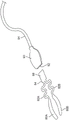
Another variation of the pliers 150 is shown in more detail in fig. 11A-11D, which show side, top, end and perspective views, respectively, in fig. 11A-11D. This variation of the forceps 150 has two juxtaposed handles 152A, 152B extending from a common pivotal connection 154. The two juxtaposed handles 152A, 152B may each terminate at their distal ends in respective tabs 156A, 156B, and the proximal end of the forceps 150 may include a proximally extending cleaning member 158, with the cleaning member 158 defining a curved or arcuate cleaning edge 160 about the periphery of the member 158. Since the gap G defined between the fins 156A, 156B may vary to accommodate a range of anatomies, the resting opening gap G may be in the range of, for example, 5.72mm to 9.09 mm.
Fig. 12A shows a detailed side view of a flap 156B, which flap 156B may have a length L of, for example, 7.37mm to 8.26mm, and a width of, for example, about 4.00 mm. The tabs 156A, 156B may be configured to have a square shape or a rectangular shape, as shown, but in other variations, the tabs may be configured in various other shapes, such as oval. To facilitate positioning of the wings 156A, 156B relative to a tissue region of the eye to be mechanically expressed, the wings 156A, 156B may be angled along their length L to define an angle 172 relative to the longitudinal axis 170 of the forceps 150. In one variation, the angle 172 may be defined as an angle of, for example, 35 °, but the angle 172 may range from, for example, 0 ° to 90 ° depending on the desired application of use.
While the cleaning edge 160 may be defined around the cleaning member 158, other variations of the pliers may have a cleaning edge defined along the edge of the tab. One example is shown in the side view of fig. 12B, which shows a flap 156B having one or more cleaning edges. For example, the distal side edge 162A of the flap 156B may be configured as a cleaning edge, while other variations may configure the distal end edge 162B or the proximal side edge 162C of one or both flaps as a cleaning edge. Other variations may also have one or two fins with one or more cleaning edges, as desired.
A cleaning member 158 extending from the proximal end of the jaws 150 may define a relatively thin edge 160 relative to the remainder of the jaws 150. In one variation, the cleaning member 158 may have a length, for example, between 10.00mm to 11.00mm or 10.67mm and a width, for example, 8.00mm to 9.00mm (e.g., 8.13mm), that gradually narrows and curves in a proximal direction into a shape, for example, an oval or semi-oval, as shown in the detailed view of fig. 13A. In other variations, the shape of the perimeter of the cleaning member 158 may be approximated as other shapes, such as semi-circular, parabolic, rectangular, triangular, etc., so long as the cleaning edge 160 is presented for use. Fig. 13B shows a detailed edge view of cleaning member 158, and further shows a cleaning edge 160 having a thickness TH. The edge 160 shown in the detailed view of fig. 13B may further define a fillet radius edge, which may be in the range of, for example, 0.05mm to 0.13 mm. The thickness TH may be in the range of, for example, between 0.40mm and 0.55mm, for example 0.46mm +/-0.05mm, however, the thickness TH may vary to, for example, 0.92mm, so long as the edge 160 is substantially thinner in material than the handles 152A, 152B of the forceps 150 to provide an effective scraping edge.
The cleaning member 158 may define a plane that is coplanar or parallel to a plane defined by the fins 156A, 156B when pressed against each other. In other variations, the plane of the cleaning member 158 may be transverse (transverse) to the plane defined by the fins 156A, 156B, or may form other angles with respect to the plane defined by the fins 156A, 156B.
In use, while the flaps 156A, 156B may be used to mechanically express directly out of the meibomian glands and/or apply pressure to the tissue region near the meibomian glands, the cleaning edge 160 may be used to scrape along the upper eyelid UL edge and/or the lower eyelid LL edge before, during, and/or after the mechanical expression, such as along the cleaning direction 180 shown in fig. 14, to remove any obstructions from the meibomian glands. Further, mechanical extrusion and/or cleaning using the jaws 150 can be performed at any time during the heat treatment with the one or more heating strips 134 and in any processing sequence. For example, the upper eyelid UL and/or the lower eyelid LL may be heat treated with the one or more heating strips 134 for a specific period of time, after which the upper eyelid and/or the lower eyelid may be mechanically squeezed out with the forceps 150 and may then be cleaned with the cleaning edge 160 after, during, and/or even before the heat treatment.
Alternatively, the tissue may be cleaned with or without mechanical extrusion with the cleaning edge 160 before, during, and/or after the thermal treatment, or the tissue may be mechanically extruded alone without the use of the cleaning edge 160. In another variation, the tissue may be first cleaned with a cleaning edge and then heat treated with a treatment strip. The cleaning process may be performed with the treatment strip worn by the patient or prior to application of the treatment strip. The forceps may then be used to mechanically express the meibomian glands. Mechanical extrusion may be accomplished after the patient wears the treatment strip or removes the treatment strip. The combination of processes may be varied depending on the desired result.
An alternative variant of the cleaning embodiment is shown in the detailed side views of fig. 15A-15C, which show a cleaning element defining a recess or groove in which the cross-section of the eyelid can be received or positioned so that cleaning can be accomplished, for example, via a sweeping motion from side to side while the eyelid edge remains within the recess. This feature may improve the safety of the instrument because the cleaning element is restrained from inadvertently intruding into the eye when moving the instrument from side to side.
Fig. 15A shows a variation showing the previously described cleaning member 158, but with a notch or groove 192 defined along a side portion of the member 158 near the proximal end of the cleaning member 158. The clearing edge 160 may also be replaced with a smooth, atraumatic proximal edge 190, and the concave edge 194 of the notch or groove 192 may define the clearing edge. The side edges 196 on both sides of the recessed edge 194 within the notch or groove 192 may be smooth and atraumatic to prevent any damage to the front and back of the eyelid during cleaning, side to side cleaning.
Because the extreme ends of the cleaning member 158 may contact the surface of the eye during use, the member 158 may be rounded or smooth to present a blunt and atraumatic surface to avoid damage to the surface of the eye, such as abrasion. Fig. 15B shows another variation in which the proximal edge 198 may be further blunted, while fig. 15C shows yet another variation in which the proximal edge 200 is rounded to present a gently curved edge or surface. In any of these variations, a layer or separating edge made of a material different from the clip may be positioned over or on the proximal edge or otherwise attached to the proximal edge, where the material is a relatively soft material, such as silicone, rubber, foam, etc., to provide additional features to prevent any damage to the eye surface.
Applications of the apparatus and methods discussed above are not limited to treatment of dry eye syndrome, but may include any number of other therapeutic applications. In addition, such devices and methods may be applied to other treatment sites in vivo where acute or chronic inflammation causes a disease or condition. The treatment strip can be custom designed accordingly to follow a path of underlying physiology, such as custom designed and contoured cooling or heating treatment strips to treat sinus and acute or chronic sinusitis, rhinitis and allergic rhinitis, joint pain and inflammation, arthritis, muscle pain, back pain, headache, trauma, sports injuries, and the like, respectively. Modifications of the above-described components and methods for carrying out the invention, combinations between different variations that are possible, and variations of aspects of the invention that are obvious to a person skilled in the art are within the scope of the claims.