CN112828359B - Robot milling attitude planning method and system based on multiple constraints of potential field method - Google Patents
Robot milling attitude planning method and system based on multiple constraints of potential field method Download PDFInfo
- Publication number
- CN112828359B CN112828359B CN202110111578.4A CN202110111578A CN112828359B CN 112828359 B CN112828359 B CN 112828359B CN 202110111578 A CN202110111578 A CN 202110111578A CN 112828359 B CN112828359 B CN 112828359B
- Authority
- CN
- China
- Prior art keywords
- robot
- coordinate system
- tool
- bcs
- end effector
- Prior art date
- Legal status (The legal status is an assumption and is not a legal conclusion. Google has not performed a legal analysis and makes no representation as to the accuracy of the status listed.)
- Active
Links
Images


Classifications
-
- B—PERFORMING OPERATIONS; TRANSPORTING
- B23—MACHINE TOOLS; METAL-WORKING NOT OTHERWISE PROVIDED FOR
- B23C—MILLING
- B23C3/00—Milling particular work; Special milling operations; Machines therefor
-
- B—PERFORMING OPERATIONS; TRANSPORTING
- B25—HAND TOOLS; PORTABLE POWER-DRIVEN TOOLS; MANIPULATORS
- B25J—MANIPULATORS; CHAMBERS PROVIDED WITH MANIPULATION DEVICES
- B25J11/00—Manipulators not otherwise provided for
- B25J11/005—Manipulators for mechanical processing tasks
- B25J11/0055—Cutting
-
- B—PERFORMING OPERATIONS; TRANSPORTING
- B25—HAND TOOLS; PORTABLE POWER-DRIVEN TOOLS; MANIPULATORS
- B25J—MANIPULATORS; CHAMBERS PROVIDED WITH MANIPULATION DEVICES
- B25J9/00—Programme-controlled manipulators
- B25J9/16—Programme controls
- B25J9/1656—Programme controls characterised by programming, planning systems for manipulators
- B25J9/1664—Programme controls characterised by programming, planning systems for manipulators characterised by motion, path, trajectory planning
Landscapes
- Engineering & Computer Science (AREA)
- Mechanical Engineering (AREA)
- Robotics (AREA)
- Numerical Control (AREA)
- Manipulator (AREA)
Abstract
本发明公开了一种基于势场法的多约束机器人铣削加工姿态规划方法和系统,属于铣削加工制造领域。本发明通过将几何物理约束转化为虚拟势场,使得被约束量在虚拟势场产生的排斥力矩的作用下,远离约束边界,从而使得生成的姿态轨迹满足几何物理约束。本发明综合考虑了机器人的冗余角与末端执行器的前倾侧倾角,进一步提高了加工质量。考虑该因素后,应用生成的轨迹进行铣削加工,加工精度有明显提高。本发明提出一种新势场函数,通过数值积分对虚拟动力学方程进行计算而求解姿态轨迹,求得的解为连续域内的数值,使得机器人轨迹在运动过程中始终保证关节运动C3连续,从而保证了生成姿态轨迹的光顺性。

The invention discloses a multi-constraint robot milling processing attitude planning method and system based on a potential field method, and belongs to the field of milling processing and manufacturing. The invention transforms the geometrical physical constraints into virtual potential fields, so that the constrained quantity is far away from the constraint boundary under the action of the repulsive moment generated by the virtual potential field, so that the generated attitude trajectory satisfies the geometrical physical constraints. The present invention comprehensively considers the redundant angle of the robot and the forward inclination angle of the end effector, and further improves the processing quality. After considering this factor, the generated trajectory is used for milling, and the machining accuracy is significantly improved. The present invention proposes a new potential field function, which calculates the virtual dynamic equation through numerical integration to solve the attitude trajectory, and the obtained solution is a numerical value in the continuous domain, so that the robot trajectory always guarantees the joint motion C3 to be continuous during the movement process, thereby The smoothness of the generated pose trajectory is guaranteed.
Description
技术领域technical field
本发明属于铣削加工制造领域,更具体地,涉及基于势场法多约束的机器人铣削加工姿态规划方法和系统。The invention belongs to the field of milling processing and manufacturing, and more particularly relates to a robot milling processing attitude planning method and system based on the potential field method with multiple constraints.
背景技术Background technique
工业机器人因其高灵活性、可编程性以及富有竞争力的成本等优点广泛应用于各类自动化生产中,面对不同的生产任务需求进行轨迹规划已成为机器人作业的刚需。针对机器人铣削加工,其对加工轨迹精度和加工力学性能要求较高,相比于其他的码垛、搬运等作业任务提出了更大的挑战;相对于传统的五轴加工,机器人铣削加工除前倾角和侧倾角外,还存在冗余角对加工力学性能产生影响,具有更高的规划难度。因此有必要开发适用于机器人多轴铣削加工的姿态轨迹规划技术。Industrial robots are widely used in various types of automated production due to their high flexibility, programmability, and competitive cost. Trajectory planning in the face of different production task requirements has become a rigid requirement for robot operations. For robotic milling, it has higher requirements on machining trajectory accuracy and machining mechanical properties, which poses greater challenges than other tasks such as palletizing and handling; compared with traditional five-axis machining, robot milling In addition to the inclination angle and the roll angle, there are also redundant angles that have an impact on the machining mechanical properties, which has a higher planning difficulty. Therefore, it is necessary to develop attitude trajectory planning technology suitable for multi-axis milling of robots.
在目前的机床与机器人姿态规划领域中,主要采用基于采样和图论的算法,对整个机器人的可达空间进行离散,对加工性能、操作性能等指标进行遍历计算,计算代价大。并且由于可达空间的离散,规划的结果需要进行光顺化处理。美国Stanford University的Khatib等学者在Autonomous Robot Vehicles上发表文章Real-Time Obstacle Avoidancefor Manipulators and Mobile Robots提出了一种基于势场法的机器人避障轨迹规划算法,将空间中的干涉赋予排斥力,目标点设置吸引力,通过两种力的作用实现机器人由初始点到终点的无干涉轨迹规划。由于仅需计算机器人所在位置的受力情况,避免了对整个可达空间的遍历;并且通过连续的计算保证了生成的轨迹光顺性。韩国Seoul NationalUniversity的Cho等学者在International Journal of Advanced ManufacturingTechnologys上发表文章International Journal of Advanced ManufacturingTechnology将势场法引入机床铣削刀具姿态轨迹规划中。法国University of Paris的Lacharnay等学者在Computer-Aided Design上发表文章A physically-based model forglobal collision avoidance in 5-axis point milling对该方法进行了改善,通过赋予全局干涉的障碍物以虚拟排斥力场,赋予预规划的刀具姿态轨迹以吸引力场,赋予刀具虚拟模态参数,使得刀具在沿规划的路径运动的规程中,通过吸引力与排斥力的作用实现高效、无全局干涉、光顺的刀具姿态规划。相关的研究仅将势场法应用于机器人避障和机床刀具姿态规划中,对于机器人多轴铣削加工姿态轨迹规划的应用目前相应的规划算法较少。In the current field of machine tool and robot attitude planning, algorithms based on sampling and graph theory are mainly used to discretize the reachable space of the entire robot, and perform traversal calculations on indicators such as machining performance and operational performance, which are expensive. And due to the discrete reachable space, the planning result needs to be smoothed. Khatib and other scholars from Stanford University in the United States published an article Real-Time Obstacle Avoidance for Manipulators and Mobile Robots on Autonomous Robot Vehicles, and proposed a robot obstacle avoidance trajectory planning algorithm based on the potential field method. Set the attraction, and realize the non-interference trajectory planning of the robot from the initial point to the end point through the action of the two forces. Since it is only necessary to calculate the force at the position of the robot, the traversal of the entire reachable space is avoided; and the smoothness of the generated trajectory is guaranteed through continuous calculation. Cho and other scholars from Seoul National University in South Korea published an article in the International Journal of Advanced ManufacturingTechnology. The International Journal of Advanced ManufacturingTechnology introduced the potential field method into the attitude trajectory planning of the milling tool of the machine tool. Scholars such as Lacharnay of the University of Paris in France published an article on Computer-Aided Design. A physically-based model for global collision avoidance in 5-axis point milling has improved this method. By giving the global interference obstacles a virtual repulsive force field, The pre-planned tool attitude trajectory is given an attractive field, and virtual modal parameters are given to the tool, so that the tool can achieve an efficient, no global interference, and smooth tool through the action of attractive and repulsive forces during the movement of the tool along the planned path. Attitude planning. Related research only applies the potential field method to robot obstacle avoidance and machine tool attitude planning, and there are currently few corresponding planning algorithms for the application of robot multi-axis milling attitude trajectory planning.
发明内容SUMMARY OF THE INVENTION
针对现有技术的缺陷和改进需求,本发明提供了基于势场法的多约束机器人铣削加工姿态规划方法和系统,其目的在于综合考虑了铣削过程中刀具姿态以及冗余角对加工精度的影响,可以实现高效生成沿刀路运动的光顺机器人姿态轨迹,有利于提升工件的加工精度。In view of the defects and improvement needs of the prior art, the present invention provides a multi-constraint robot milling attitude planning method and system based on the potential field method, the purpose of which is to comprehensively consider the influence of the tool attitude and redundant angles on the machining accuracy during the milling process , which can efficiently generate a smooth robot attitude trajectory along the tool path, which is beneficial to improve the machining accuracy of the workpiece.
为实现上述目的,按照本发明的第一方面,提供了一种基于势场法多约束的机器人铣削加工姿态规划方法,该方法包括以下步骤:In order to achieve the above object, according to the first aspect of the present invention, a multi-constraint robot milling attitude planning method based on the potential field method is provided, and the method includes the following steps:
S1.获取刀具路径;S1. Get the tool path;
S2.初始化机器人末端执行器的虚拟转动惯量M、机器人末端执行器的虚拟转动阻尼C,初始化第一个刀位点处机器人末端执行器的姿态,初始化机器人各关节角约束值θlim和阈值θ0、刀具前倾角约束值llim和阈值l0、侧倾角约束值tlim和阈值t0,以及误差指标约束值δlim和阈值δ0;S2. Initialize the virtual moment of inertia M of the robot end effector, the virtual rotational damping C of the robot end effector, initialize the posture of the robot end effector at the first tool position point, and initialize the constraint value θ lim and threshold θ of each joint angle of the robot. 0 , the tool rake angle constraint value l lim and the threshold value l 0 , the roll angle constraint value t lim and the threshold value t 0 , and the error index constraint value δ lim and the threshold value δ 0 ;
S3.对于刀具路径中每一个刀位点,进行以下处理,直至整个刀具路径上的刀位点上的机器人末端执行器姿态规划完成:S3. For each tool position point in the tool path, perform the following processing until the robot end effector pose planning on the tool position point on the entire tool path is completed:
(1)以刀具路径中刀位点为坐标原点,以工件设计表面法矢方向为ZECS轴,以刀具路径的切矢方向为XECS轴,通过右手法则确立YECS轴,从而建立ECS坐标系;(1) Take the tool position point in the tool path as the coordinate origin, take the normal vector direction of the workpiece design surface as the Z ECS axis, take the tangent vector direction of the tool path as the X ECS axis, and establish the Y ECS axis through the right-hand rule to establish the ECS coordinates Tie;
(2)基于TCS与BCS坐标系的关系以及机器人运动学,计算机器人各关节角θ;基于TCS和ECS坐标系的关系,计算刀具前倾角l和侧倾角t;基于TCS、BCS和ECS坐标系的关系以及机器人刚度与铣削力学,计算加工误差指标δ;(2) Calculate the joint angle θ of the robot based on the relationship between the TCS and BCS coordinate systems and the kinematics of the robot; calculate the tool rake angle l and roll angle t based on the relationship between the TCS and ECS coordinate systems; The relationship between the robot stiffness and milling mechanics, and the machining error index δ is calculated;
(3)分别计算实际值与约束值的差值绝对值,得到θ′,l′,t′,δ′;(3) Calculate the absolute value of the difference between the actual value and the constraint value, respectively, to obtain θ′, l′, t′, δ′;
(4)将计算出的θ′,l′,t′,δ′分别代入排斥力矩函数并对求出的各排斥力矩求和,计算得到该刀位点上末端执行器受到的总排斥力矩,所述排斥力矩函数是对势场函数求偏导所得,所述势场函数必须同时满足以下限定:(4) Substitute the calculated θ', l', t', and δ' into the repulsive moment function respectively and sum up the calculated repulsive moments, and calculate the total repulsive moment received by the end effector on the tool position, The repulsive moment function is obtained by taking the partial derivative of the potential field function, and the potential field function must satisfy the following constraints at the same time:
1)在θ′,l′,t′,δ′中的任一个趋于0时,势场趋于无穷大;1) When any of θ′, l′, t′, and δ′ tends to 0, the potential field tends to infinity;
2)在θ′,l′,t′,δ′中的任一个大于对应阈值时,势场恒等于0;2) When any of θ′, l′, t′, and δ′ is greater than the corresponding threshold, the potential field is always equal to 0;
3)至少保证二阶偏导连续;3) At least the second-order partial derivatives are guaranteed to be continuous;
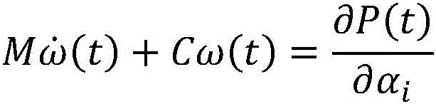
(5)将得到的总排斥力矩代入虚拟动力学方程,求解得到下一个刀位点处的机器人末端执行器姿态,所述虚拟动力学方程如下:(5) Substitute the obtained total repulsive moment into the virtual dynamic equation, and solve to obtain the robot end effector attitude at the next tool position. The virtual dynamic equation is as follows:
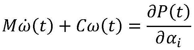
其中,M是机器人末端执行器的虚拟转动惯量,C为虚拟转动阻尼,P(t)是总势场函数,αi是TCS坐标系依次绕BCS的X轴、Y轴或Z轴旋转的欧拉角,

有益效果:本发明将机器人铣削过程中的约束条件转化为势场函数,实现对于给定第一个刀位点上的机器人末端执行器的姿态后,通过势场函数计算不同约束条件对应的排斥力矩,并对虚拟动力学方程进行求解,从而实现整个刀路上的机器人末端执行器姿态轨迹的规划。Beneficial effects: the present invention converts the constraints in the robot milling process into potential field functions, and realizes that the repulsion corresponding to different constraints is calculated by the potential field function after the posture of the robot end effector on the first tool position is given. torque, and solve the virtual dynamic equation, so as to realize the planning of the robot end effector attitude trajectory on the entire tool path.
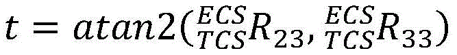
优选地,刀具侧倾角t计算公式如下:Preferably, the calculation formula of the tool roll angle t is as follows:
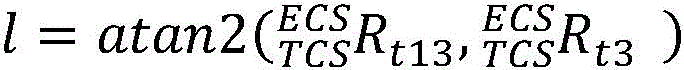
刀具前倾角l计算公式如下:The calculation formula of the tool rake angle l is as follows:
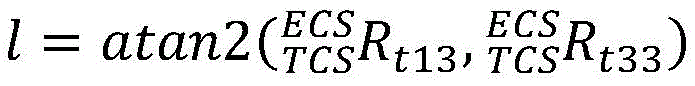
其中,

有益效果:本发明通过在机器人铣削加工中定义前倾角与侧倾角,将现有的机器人加工中的仅冗余角规划拓展至前倾角、侧倾角、冗余角的共同规划。从而进一步提高了机器人的铣削能力。Beneficial effects: The present invention expands the redundant angle planning in the existing robot processing to the joint planning of the front inclination angle, the roll angle and the redundant angle by defining the front inclination angle and the roll angle in the robot milling process. Thus, the milling capability of the robot is further improved.
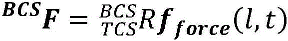
优选地,所述加工误差指标定义为:将平均铣削力作用在机器人末端执行器的刀具上时,产生的变形在工件表面法矢方向的分量,计算过程如下:Preferably, the machining error index is defined as the component of the deformation in the normal vector direction of the workpiece surface when the average milling force acts on the tool of the robot end effector, and the calculation process is as follows:
(1)通过TCS到BCS的旋转矩阵
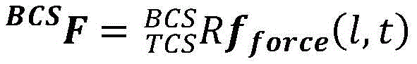
其中,fforce(l,t)为刀具前倾角l和侧倾角t时的TCS下的平均铣削力的计算函数;Among them, f force (l, t) is the calculation function of the average milling force under TCS when the tool rake angle l and roll angle t are;
(2)基于机器人关节角θ计算机器人末端刚度矩阵K;(2) Calculate the stiffness matrix K of the robot end based on the robot joint angle θ;
K=fstiffness(θ)K=f stiffness (θ)
其中,fstiffness(θ)为机器人末端刚度矩阵K的计算函数;Among them, f stiffness (θ) is the calculation function of the stiffness matrix K of the robot end;
(3)计算加工误差指标δ(3) Calculate the machining error index δ
δ=|BCSZECS(CLi)K-1 BCSF|δ=| BCS Z ECS (CL i )K -1 BCS F|
其中,CLi是第i个刀位点在BCS坐标系下的位置坐标,BCSZECS(CLi)是第i个刀位点处的ECS的Z轴在BCS下的向量坐标。Among them, CL i is the position coordinate of the ith tool location point in the BCS coordinate system, and BCS Z ECS (CL i ) is the vector coordinate of the Z axis of the ECS at the ith tool location point under BCS.
有益效果:本发明通过定义机器人加工误差指标δ,考虑了不同机器人姿态对机器人末端刚度与铣削力的影响。通过对加工误差指标的约束,结合所提出的势场算法,实现了高精度机器人铣削姿态轨迹规划。Beneficial effects: The present invention considers the influence of different robot postures on the stiffness of the robot end and the milling force by defining the robot machining error index δ. By constraining the machining error index, combined with the proposed potential field algorithm, the high-precision robot milling attitude trajectory planning is realized.
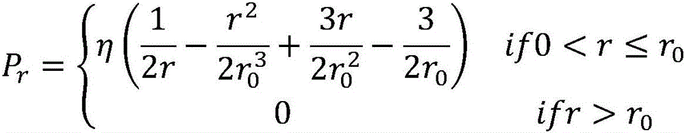
优选地,以r为约束条件的势场函数如下:Preferably, the potential field function with r as the constraint condition is as follows:
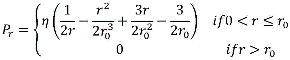
其中,η为调节参数,r=θ′或者l′或者t′或者δ′。Among them, η is an adjustment parameter, r=θ' or l' or t' or δ'.
有益效果:本发明提出了一种考虑多约束下的机器人末端执行器姿态轨迹规划势场函数模型。由于该势场函数在θ′,l′,t′,δ′趋于0时,势能趋于无穷大,从而保证了生成轨迹满足约束条件。由于该势场函数在θ′,l′,t′,δ′中的任一个大于阈值r0时,势能恒等于0,避免了在距离约束边界较远时,排斥力矩对机器人末端姿态产生影响,保证了机器人末端执行器运动的平稳性。由于该势场函数至少保证二阶偏导连续,保证了机器人末端执行器运行的C3连续性。Beneficial effects: The present invention proposes a potential field function model for robot end effector attitude trajectory planning considering multiple constraints. Since the potential field function tends to be infinite when θ′, l′, t′, and δ′ tend to 0, it is ensured that the generated trajectory satisfies the constraints. Since the potential energy of the potential field function is always equal to 0 when any of θ', l', t', and δ' is greater than the threshold r 0 , it avoids the influence of the repulsive moment on the attitude of the robot end when it is far away from the constraint boundary. , to ensure the stability of the robot end effector movement. Since the potential field function at least guarantees the continuity of the second-order partial derivatives, the C3 continuity of the robot end effector operation is guaranteed.
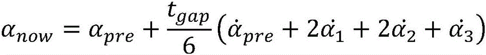
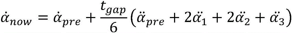
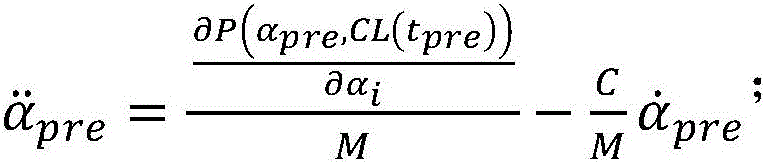
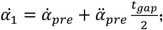
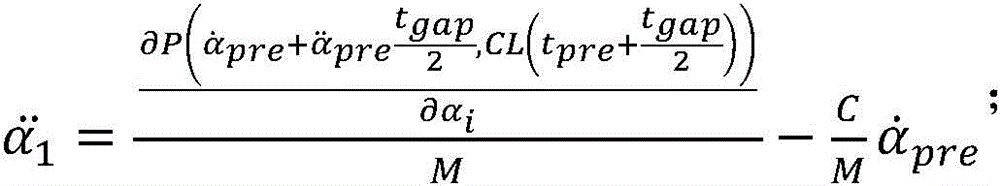
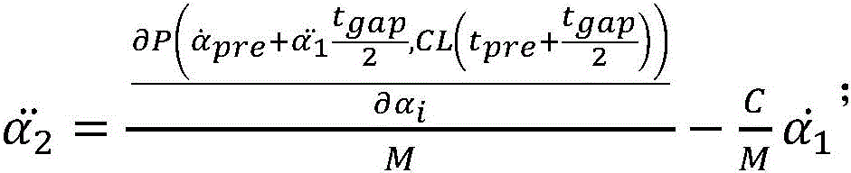
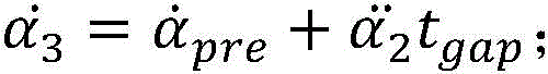
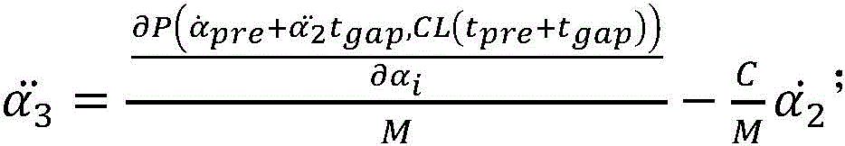
优选地,步骤(5)采用龙格库塔求解,得到Preferably, step (5) adopts Runge-Kutta solution to obtain

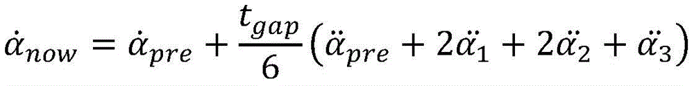
其中,in,
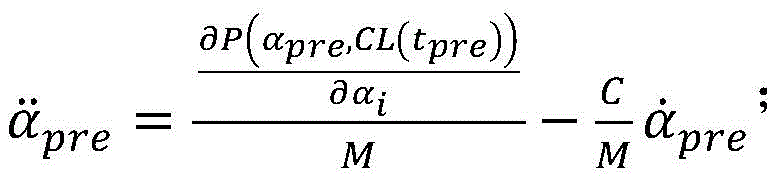
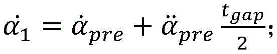
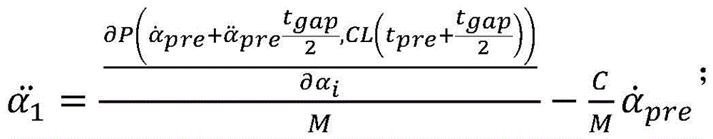

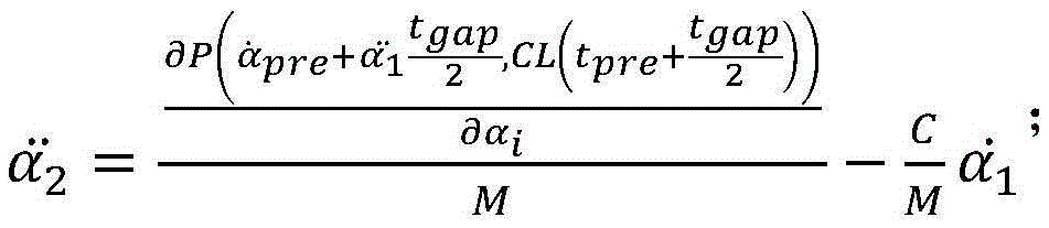
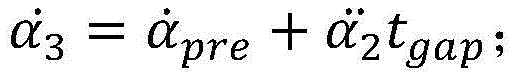
其中,αpre,
有益效果:本发明将机器人姿态轨迹规划问题转化为虚拟动力学方程的求解,在给定初始刀位点上机器人末端执行器姿态,通过龙格库塔数值积分方法实现了后续刀位点上的机器人末端执行器姿态的规划。Beneficial effects: The present invention transforms the robot attitude trajectory planning problem into the solution of the virtual dynamic equation, and at the given initial tool position point, the robot end effector attitude is realized by the Runge-Kutta numerical integration method on the subsequent tool position point. Planning of robot end effector pose.
优选地,步骤S3的约束值还包括机器人姿态奇异性条件数、奇异点、振动,能量中的至少一个。Preferably, the constraint value in step S3 also includes at least one of the robot attitude singularity condition number, singularity point, vibration, and energy.
有益效果:本发明通过势场函数将约束转化为势能,产生排斥力矩,从而进行机器人末端执行器姿态轨迹的规划。由于该势场函数具有通用性,还可将其应用于机器人姿态奇异性条件数、奇异点、振动,能量等约束,实现不同工况下不同约束下的机器人末端执行器姿态轨迹规划。Beneficial effects: the present invention converts constraints into potential energy through a potential field function to generate a repulsive moment, so as to plan the attitude trajectory of the robot end effector. Due to the generality of the potential field function, it can also be applied to the constraints of the singularity condition number, singularity, vibration, and energy of the robot posture, so as to realize the posture trajectory planning of the robot end effector under different constraints under different working conditions.
为实现上述目的,按照本发明的第二方面,提供了一种基于势场法的多约束机器人铣削加工姿态规划系统,包括:计算机可读存储介质和处理器;In order to achieve the above object, according to the second aspect of the present invention, a multi-constraint robot milling attitude planning system based on the potential field method is provided, including: a computer-readable storage medium and a processor;
所述计算机可读存储介质用于存储可执行指令;the computer-readable storage medium for storing executable instructions;
所述处理器用于读取所述计算机可读存储介质中存储的可执行指令,执行第一方面所述的基于势场法的多约束机器人铣削加工姿态规划方法。The processor is configured to read the executable instructions stored in the computer-readable storage medium, and execute the multi-constraint robot milling attitude planning method based on the potential field method described in the first aspect.
总体而言,通过本发明所构思的以上技术方案,能够取得以下有益效果:In general, through the above technical solutions conceived by the present invention, the following beneficial effects can be achieved:
(1)本发明通过将几何物理约束转化为虚拟势场,在约束极限值处对应的势能为无穷大,使得被约束量在虚拟势场产生的排斥力的作用下,远离边界,从而生成的姿态轨迹满足几何-物理约束。(1) The present invention transforms the geometric and physical constraints into a virtual potential field, and the corresponding potential energy at the limit value of the constraint is infinite, so that the constrained quantity is far away from the boundary under the action of the repulsive force generated by the virtual potential field, so that the generated attitude The trajectory satisfies the geometry-physics constraints.
(2)末端执行器的前倾侧倾角也会对机器人的力学性能造成影响,从而对加工精度有影响。本发明综合考虑了机器人的冗余角与末端执行器的前倾侧倾角,进一步提高了加工质量。考虑该因素后,应用生成的轨迹进行铣削加工,对应的加工精度有明显提高。(2) The forward tilt angle of the end effector will also affect the mechanical properties of the robot, thereby affecting the machining accuracy. The present invention comprehensively considers the redundant angle of the robot and the forward inclination angle of the end effector, and further improves the processing quality. After taking this factor into consideration, the generated trajectory is used for milling, and the corresponding machining accuracy is significantly improved.
(3)本发明提出一种新势场函数,通过数值积分对虚拟动力学方程进行计算而求解姿态轨迹,求得的解为连续域内的数值,使得机器人轨迹在运动过程中始终保证C3连续,从而保证了生成姿态轨迹的光顺性。(3) The present invention proposes a new potential field function, which calculates the virtual dynamic equation through numerical integration to solve the attitude trajectory, and the obtained solution is a numerical value in the continuous domain, so that the robot trajectory can always ensure that C3 is continuous during the movement process, Thus, the smoothness of the generated attitude trajectory is guaranteed.
附图说明Description of drawings
图1是本发明提供的一种基于势场法的多约束机器人铣削加工姿态规划方法的总体流程图;Fig. 1 is the overall flow chart of a kind of multi-constraint robot milling processing attitude planning method based on potential field method provided by the present invention;
图2是本发明提供的机器人六轴铣削加工过程以及BCS,TCS与ECS的示意图;2 is a schematic diagram of a robot six-axis milling process and BCS, TCS and ECS provided by the present invention;
图3是本发明提供的机器人基坐标系BCS和刀具坐标系TCS之间的旋转变换关系;Fig. 3 is the rotation transformation relation between robot base coordinate system BCS and tool coordinate system TCS provided by the present invention;
图4是本发明提供的机器人坐标系的旋转变换关系图。FIG. 4 is a rotation transformation relationship diagram of the robot coordinate system provided by the present invention.
具体实施方式Detailed ways
为了使本发明的目的、技术方案及优点更加清楚明白,以下结合附图及实施例,对本发明进行进一步详细说明。应当理解,此处所描述的具体实施例仅仅用以解释本发明,并不用于限定本发明。此外,下面所描述的本发明各个实施方式中所涉及到的技术特征只要彼此之间未构成冲突就可以相互组合。In order to make the objectives, technical solutions and advantages of the present invention clearer, the present invention will be further described in detail below with reference to the accompanying drawings and embodiments. It should be understood that the specific embodiments described herein are only used to explain the present invention, but not to limit the present invention. In addition, the technical features involved in the various embodiments of the present invention described below can be combined with each other as long as they do not conflict with each other.
如图1所示,本发明提供了一种基于势场法的多约束机器人铣削加工姿态轨迹规划方法。基于机器人的运动学与力学模型,给出了相应的约束条件,建立了给定刀路下的机器人姿态轨迹规划模型;然后,为了保证生成的姿态轨迹满足几何物理约束并具有C3光顺性,提出了一种势场模型,并给出了势场产生的虚拟排斥力矩的算法;结合排斥力矩与赋予机器人末端执行器的虚拟模态参数,构建了机器人末端执行器姿态的动力学方程;最后,通过数值积分算法,实现了机器人姿态轨迹的规划。As shown in FIG. 1 , the present invention provides a multi-constraint robot milling attitude trajectory planning method based on the potential field method. Based on the kinematics and mechanical model of the robot, the corresponding constraints are given, and the robot attitude trajectory planning model under the given tool path is established; then, in order to ensure that the generated attitude trajectory satisfies the geometric and physical constraints and has C3 smoothness, A potential field model is proposed, and the algorithm of the virtual repulsive moment generated by the potential field is given. Combined with the repulsive moment and the virtual modal parameters given to the robot end effector, the dynamic equation of the robot end effector attitude is constructed. , through the numerical integration algorithm, the robot attitude trajectory planning is realized.
1.机器人姿态轨迹规划模型1. Robot attitude trajectory planning model
为了方便对机器人铣削加工过程进行描述,如图2所示,建立机器人铣削加工中的相关坐标系,包括机器人基坐标系(BCS)、加工坐标系(ECS)和机器人末端执行器坐标系(TCS)。其中,BCS是固定于机器人的坐标系;TCS以机器人末端执行器上的刀具中心为原点,刀具轴线方向为ZTCS轴,YTCS轴垂直于刀具轴线方向和进给方向,通过右手法则确立XTCS轴。ECS根据刀具路径进行定义,以加工中刀位点为坐标原点,以工件设计表面法矢为ZECS轴,以刀具路径的切矢方向为XECS轴,通过右手法则确立YECS轴。In order to facilitate the description of the robot milling process, as shown in Figure 2, the relevant coordinate systems in the robot milling process are established, including the robot base coordinate system (BCS), the machining coordinate system (ECS) and the robot end effector coordinate system (TCS) ). Among them, BCS is the coordinate system fixed to the robot; TCS takes the tool center on the robot end effector as the origin, the tool axis direction is the Z TCS axis, the Y TCS axis is perpendicular to the tool axis direction and the feed direction, and X is established by the right-hand rule. TCS axis. ECS is defined according to the tool path. The tool position in processing is used as the coordinate origin, the normal vector of the workpiece design surface is the Z ECS axis, the tangent vector direction of the tool path is the X ECS axis, and the Y ECS axis is established by the right-hand rule.
机器人多轴铣削加工如图2所示,可以看作刀尖点沿着给定的刀路做平移运动,同时机器人末端执行器绕着刀尖点旋转。刀具路径由一系列刀位点CL构成,可以通过CAM软件生成。刀具姿态,即机器人末端执行器的姿态为规划对象,通过欧拉角α对机器人末端执行器的姿态在基坐标系BCS下的数学关系进行描述。BCS与TCS的关系如图3所示。TCS在BCS下的位姿用欧拉角α的齐次变换矩阵描述为:Robotic multi-axis milling is shown in Figure 2. It can be seen that the tool nose point moves in translation along a given tool path, while the robot end effector rotates around the tool nose point. The toolpath consists of a series of tool positions CL, which can be generated by CAM software. The tool attitude, that is, the attitude of the robot end effector, is the planning object, and the mathematical relationship of the robot end effector attitude in the base coordinate system BCS is described by the Euler angle α. The relationship between BCS and TCS is shown in Figure 3. The pose of TCS under BCS is described by the homogeneous transformation matrix of Euler angle α as:

αx、αy和αz为绕BCS的X轴、Y轴和Z轴旋转的欧拉角,CLx、CLy和CLz为刀位点相对于基座标系的位置。α x , α y and α z are the Euler angles rotated around the X, Y and Z axes of the BCS, and CL x , CL y and CL z are the positions of the tool position relative to the base frame.
为了生成机器人多轴铣削的加工姿态轨迹,需要综合满足关节角范围,刀具姿态角与加工误差指标的约束。另一方面,需要保证光顺性来保证机器人运行时的动态特性和刀具的运动性能,因此轨迹需要保证C3连续。因此轨迹的规划模型为:In order to generate the machining attitude trajectory of the robot multi-axis milling, it is necessary to comprehensively satisfy the constraints of the joint angle range, the tool attitude angle and the machining error index. On the other hand, the smoothness needs to be guaranteed to ensure the dynamic characteristics of the robot and the kinematic performance of the tool during operation, so the trajectory needs to ensure that C3 is continuous. Therefore, the planning model of the trajectory is:
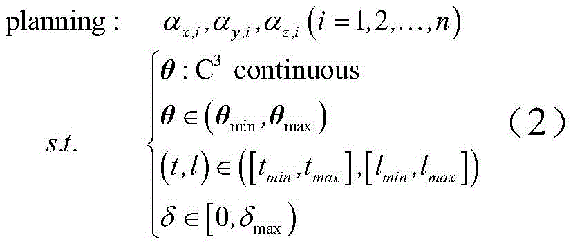
式中,i指刀路轨迹上刀位点的序号;θ,l,t,δ分别为机器人关节角、刀具姿态前倾角、侧倾角与加工误差指标。In the formula, i refers to the serial number of the tool position point on the tool path trajectory; θ, l, t, δ are the robot joint angle, the tool attitude forward inclination angle, the roll angle and the machining error index, respectively.
2机器人末端执行器姿态约束2 Robot end effector pose constraints
2.1关节角约束2.1 Joint angle constraints
由于机器人各关节角θ的运动范围一定,因此为避免规划的机器人姿态不可达,对机器人末端执行器姿态的可达空间进行约束。Since the motion range of each joint angle θ of the robot is certain, in order to avoid the unreachable robot posture, the reachable space of the robot end effector posture is constrained.
对于给定欧拉角αx,αy,αz的机器人末端执行器姿态,可以得到机器人的末端执行器位姿矩阵

结合机器人的关节角θ范围(θmin,θmax),得机器人末端执行器的姿态的约束条件,即:Combined with the joint angle θ range of the robot (θ min , θ max ), the constraints on the posture of the robot end effector are obtained, namely:
θ=f1(αx,αy,αz)∈(θmin,θmax) (4)θ=f 1 (α x ,α y ,α z )∈(θ min ,θ max ) (4)
2.2刀具姿态角约束2.2 Tool attitude angle constraints
在五轴铣削加工领域,为对刀具姿态进行描述,使用了前倾角、侧倾角的概念。为避免出现干涉碰撞需要将前倾角、侧倾角限制在一定的范围内。同时由于球头刀等刀具铣削过程中,刀尖点的线速度为零,不利于切削,因此,需要保证刀具的前倾角大于零度以避免刀尖点参与切削。In the field of five-axis milling, in order to describe the tool attitude, the concepts of rake angle and roll angle are used. In order to avoid interference collisions, it is necessary to limit the forward and roll angles within a certain range. At the same time, during the milling process of tools such as ball-end cutters, the linear velocity of the tool nose point is zero, which is not conducive to cutting. Therefore, it is necessary to ensure that the rake angle of the tool is greater than zero to prevent the tool nose point from participating in cutting.
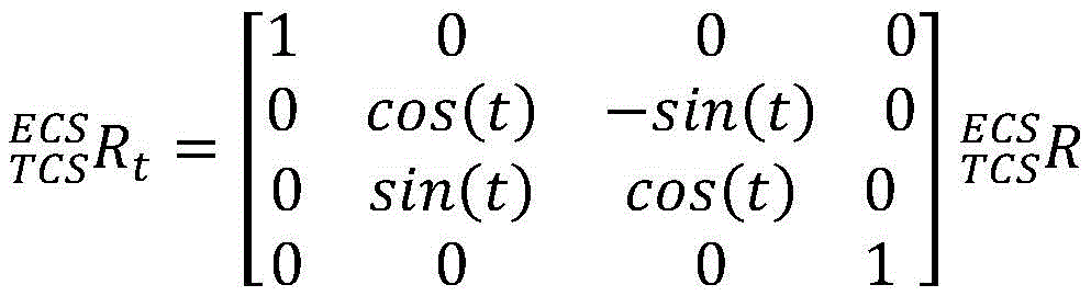
与传统机床铣削不同,由于工业机器人具有冗余自由度。为表征机器人这一姿态特性,对工业机器人多轴铣削的前倾侧倾角与冗余角进行规定。如图4所示,最初TCS与ECS重合,TCS绕ECS的Z轴旋转冗余角s,然后TCS绕ECS的Y轴旋转前倾角l,最后TCS绕ECS的X轴旋转侧倾角t。齐次变换矩阵
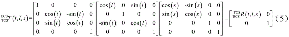
在给定机器人末端执行器的姿态欧拉角与刀位点坐标后,可由公式(1)得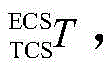
刀具侧倾角t计算公式如下:The formula for calculating the tool roll angle t is as follows:
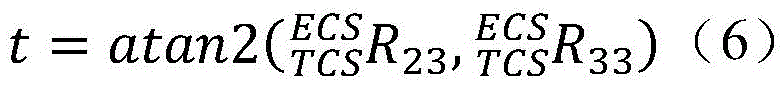
刀具前倾角l计算公式如下:The calculation formula of the tool rake angle l is as follows:
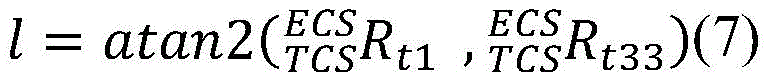
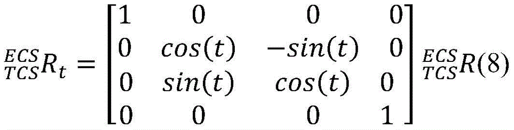
其中,


由此,刀具姿态角与冗余角的约束转化成对欧拉角的隐式约束,即:As a result, the constraints of the tool attitude angle and the redundant angle are transformed into implicit constraints on the Euler angles, namely:
[t,l,s]=f2(αx,αy,αz)∈([tmin,tmax],[lmin,lmax]) (10)[t,l,s]=f 2 (α x ,α y ,α z )∈([t min ,t max ],[l min ,l max ]) (10)
2.3加工误差约束2.3 Processing Error Constraints
为了对加工精度进行表征,将平均切削力作用机器人末端刀具上时,产生的变形在工件表面法矢方向的分量定义为加工误差指标。In order to characterize the machining accuracy, the component of the deformation in the normal vector direction of the workpiece surface when the average cutting force acts on the end tool of the robot is defined as the machining error index.
(1)通过TCS到BCS的旋转矩阵

其中,fforce(l,t)为刀具前倾角l和侧倾角t时的TCS下的平均铣削力的计算函数;Among them, f force (l, t) is the calculation function of the average milling force under TCS when the tool rake angle l and roll angle t are;
(2)基于机器人关节角θ计算机器人末端刚度矩阵K;(2) Calculate the stiffness matrix K of the robot end based on the robot joint angle θ;
K=fstiffness(θ) (12)K=f stiffness (θ) (12)
其中,fstiffness(θ)为机器人末端刚度矩阵K的计算函数;Among them, f stiffness (θ) is the calculation function of the stiffness matrix K of the robot end;
(3)计算加工误差指标δ(3) Calculate the machining error index δ
δ=|BCSZECS(CLi)K-1 BCSF| (13)δ=| BCS Z ECS (CL i )K -1 BCS F| (13)
其中,CLi是第i个刀位点在BCS坐标系下的位置坐标,BCSZECS(CLi)是第i个刀位点处的ECS的Z轴在BCS下的向量坐标。Among them, CL i is the position coordinate of the ith tool position point under the BCS coordinate system, and BCSZ ECS (CL i ) is the vector coordinate of the Z axis of the ECS at the ith tool position point under BCS.
结合式(3)(9)(11)(12)(13),将上式转化为机器人末端执行器姿态欧拉角的函数f3:Combined with equations (3)(9)(11)(12)(13), the above equation is transformed into the function f 3 of the Euler angle of the robot end-effector attitude:
δ=|ZECS(CL)K-1(f1(αx,αy,αz))BCSF(f3(αx,αy,αz))|=f3(αx,αy,αz)δ=|Z ECS (CL)K -1 (f 1 (α x ,α y ,α z )) BCS F(f 3 (α x ,α y ,α z ))|=f 3 (α x ,α y ,α z )
为保证加工精度,因此对误差指标进行限制:In order to ensure the machining accuracy, the error index is limited:
δ=f3(αx,αy,αz)∈[0,δmax)δ=f 3 (α x ,α y ,α z )∈[0,δ max )
3.势场算法3. Potential Field Algorithm
势场算法通过将不同姿态下的指标θ,l,t,δ与约束极限值之间的差值的绝对值θ′,l′,t′,δ′转化为虚拟势能,构建势场。通过势场产生的排斥力矩对机器人末端执行器姿态产生作用,使得机器人末端刀尖点在沿刀具路径进行运动的过程中,自动远离约束极限值,生成满足约束的机器人末端执行器姿态轨迹。The potential field algorithm constructs a potential field by converting the absolute values of the differences θ', l', t', δ' between the indicators θ, l, t, δ and the constraint limit values under different attitudes into virtual potential energy. The repulsive moment generated by the potential field acts on the robot end effector posture, so that the robot end tool tip automatically moves away from the constraint limit value during the movement along the tool path, and generates a robot end effector posture trajectory that satisfies the constraints.
为实现该方法,一方面提出了适用于机器人多轴铣削的势场函数与排斥力矩函数,另一方面提出了机器人多轴加工姿态虚拟动力学方程,并提供了求解方法过程。In order to realize this method, on the one hand, the potential field function and repulsive moment function suitable for the multi-axis milling of the robot are proposed;
3.1势场函数与排斥力矩函数的构建3.1 Construction of Potential Field Function and Repulsive Moment Function
生成的姿态轨迹应保证:(1)保证在任意刀位点上的机器人末端执行器姿态均满足约束条件;(2)机器人关节角的运动轨迹光顺。The generated attitude trajectory should ensure: (1) Ensure that the robot end-effector attitude at any tool position satisfies the constraints; (2) The motion trajectory of the robot joint angle is smooth.
为保证条件(1),要求势能函数在机器人姿态区域极限位置时,虚拟势能趋于无穷大。In order to ensure condition (1), the virtual potential energy tends to infinity when the potential energy function is required to be at the limit position of the robot attitude region.
为保证条件(2)为避免生成的机器人轨迹震荡,要求①机器人姿态在距离大于阈值r0时,势能为零;要求②生成的轨迹具有C3的连续性,即所有的位置处关节角的急动度θ(3)应保证连续。In order to ensure condition (2), in order to avoid the generated robot trajectory from oscillation, it is required that ① the potential energy of the robot is zero when the distance is greater than the threshold r 0 ; ② the generated trajectory is required to have the continuity of C 3 , that is, the joint angles at all positions are equal to each other. Jerk θ (3) should be guaranteed to be continuous.
由此,所述势场函数必须同时满足以下限定:Therefore, the potential field function must simultaneously satisfy the following constraints:
1)在θ′,l′,t′,δ′中的任一个趋于0时,势场趋于无穷大;1) When any of θ′, l′, t′, and δ′ tends to 0, the potential field tends to infinity;
2)在θ′,l′,t′,δ′中的任一个大于阈值r0时,势场恒等于0;2) When any of θ′, l′, t′, δ′ is greater than the threshold r 0 , the potential field is always equal to 0;
3)至少保证二阶偏导连续;3) At least the second-order partial derivatives are guaranteed to be continuous;
即:which is:
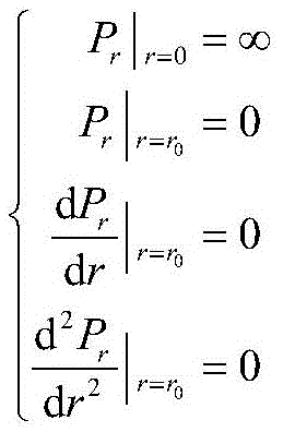
其中,r=θ′或者l′或者t′或者δ′。由此得到势场函数:Wherein, r=θ' or l' or t' or δ'. This leads to the potential field function:

势场排斥力矩为虚拟势能关于机器人末端执行器姿态欧拉角的导数。对于机器人多轴铣削,由于欧拉角具有三个维度,因此排斥力矩为:The repulsive moment of the potential field is the derivative of the virtual potential energy with respect to the Euler angle of the robot end effector attitude. For robotic multi-axis milling, since Euler angles have three dimensions, the repulsive moment is:

通过以上的计算,实现了将关节角,姿态角以及误差指标转化为排斥力矩作用在机器人末端执行器上,对末端执行器姿态对应的欧拉角进行影响。Through the above calculation, it is realized that the joint angle, attitude angle and error index are converted into repulsive moment to act on the robot end effector, which affects the Euler angle corresponding to the end effector attitude.
3.2虚拟动力学方程建模与求解3.2 Modeling and solving of virtual dynamic equations
根据前面关于势场法的叙述,通过赋予机器人末端执行器虚拟模态参数,在约束产生的虚拟排斥力矩的作用下,可以建立相应的虚拟动力学方程,即:According to the previous description of the potential field method, by assigning virtual modal parameters to the robot end effector, under the action of the virtual repulsive moment generated by the constraint, the corresponding virtual dynamic equation can be established, namely:

其中,M是机器人末端执行器的虚拟转动惯量,C为虚拟转动阻尼,P(t)是总势场函数,αi是TCS坐标系依次绕BCS的X轴、Y轴或Z轴旋转的欧拉角,
通过龙格库塔法分别对三个方向进行求解,从而实现对轨迹的规划。The three directions are solved by the Runge-Kutta method, so as to realize the planning of the trajectory.
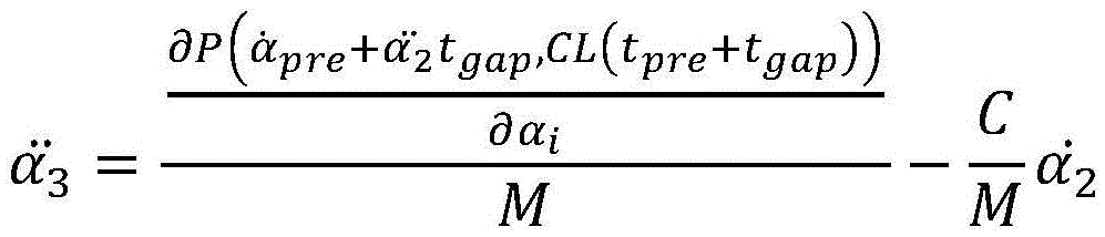
通过龙格库塔法得到Obtained by Runge-Kutta method

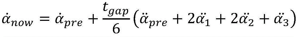
其中,in,

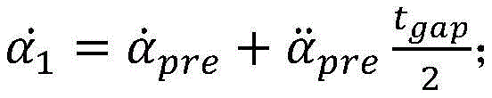
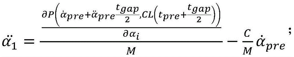
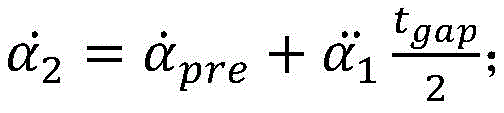


其中,αpre,
由此实现了,机器人多轴铣削时,刀具沿给定刀路由初始刀位点在向路径末端的运动过程中,机器人末端执行器姿态轨迹的自动规划。This realizes the automatic planning of the robot end effector's attitude trajectory during the movement of the initial tool position point along the given tool path to the end of the path during multi-axis milling of the robot.
本领域的技术人员容易理解,以上所述仅为本发明的较佳实施例而已,并不用以限制本发明,凡在本发明的精神和原则之内所作的任何修改、等同替换和改进等,均应包含在本发明的保护范围之内。Those skilled in the art can easily understand that the above are only preferred embodiments of the present invention, and are not intended to limit the present invention. Any modifications, equivalent replacements and improvements made within the spirit and principles of the present invention, etc., All should be included within the protection scope of the present invention.
Claims (7)


Priority Applications (1)
| Application Number | Priority Date | Filing Date | Title |
|---|---|---|---|
| CN202110111578.4A CN112828359B (en) | 2021-01-27 | 2021-01-27 | Robot milling attitude planning method and system based on multiple constraints of potential field method |
Applications Claiming Priority (1)
| Application Number | Priority Date | Filing Date | Title |
|---|---|---|---|
| CN202110111578.4A CN112828359B (en) | 2021-01-27 | 2021-01-27 | Robot milling attitude planning method and system based on multiple constraints of potential field method |
Publications (2)
| Publication Number | Publication Date |
|---|---|
| CN112828359A CN112828359A (en) | 2021-05-25 |
| CN112828359B true CN112828359B (en) | 2022-02-01 |
Family
ID=75931909
Family Applications (1)
| Application Number | Title | Priority Date | Filing Date |
|---|---|---|---|
| CN202110111578.4A Active CN112828359B (en) | 2021-01-27 | 2021-01-27 | Robot milling attitude planning method and system based on multiple constraints of potential field method |
Country Status (1)
| Country | Link |
|---|---|
| CN (1) | CN112828359B (en) |
Families Citing this family (10)
| Publication number | Priority date | Publication date | Assignee | Title |
|---|---|---|---|---|
| TWI764820B (en) * | 2021-08-27 | 2022-05-11 | 正崴精密工業股份有限公司 | Robot arm obstacle avoidance method and robot arm obstacle avoidance system |
| CN113894782B (en) * | 2021-10-12 | 2023-01-17 | 华中科技大学 | Method and system for attitude optimization of robot milling machining based on stiffness orientation |
| CN113867260B (en) * | 2021-10-14 | 2023-05-30 | 苏州大学 | Robot curved surface machining joint track generation method adopting numerical integration |
| CN114029956B (en) * | 2021-11-24 | 2023-05-12 | 苏州大学 | High-order smooth robot curved surface machining process optimization method considering singular point and collision avoidance |
| CN114179114B (en) * | 2022-02-17 | 2022-05-06 | 杭州飞钛航空智能装备有限公司 | Hole making normal alignment method, hole making tail end execution device and hole making robot |
| CN114936025B (en) * | 2022-05-28 | 2025-03-04 | 石家庄铁道大学 | A STEP-NC online interpretation method for machining robots |
| CN114833848B (en) * | 2022-06-02 | 2023-09-15 | 大连理工大学 | A stiffness-constrained tool axis vector and redundancy integrated planning method for robot milling |
| CN115145221B (en) * | 2022-07-05 | 2024-07-19 | 湖南大学 | Workpiece and cutter pose calibration method based on robot edge milling error tracing |
| CN115229772B (en) * | 2022-08-23 | 2023-07-18 | 深圳市越疆科技股份有限公司 | Robot and its control method, device, equipment, storage medium, and mechanical arm |
| CN116595721B (en) * | 2023-04-25 | 2025-07-22 | 合肥工业大学 | U-K method-based double-robot mirror image milling pose collaborative dynamics modeling method |
Citations (5)
| Publication number | Priority date | Publication date | Assignee | Title |
|---|---|---|---|---|
| US5396160A (en) * | 1991-03-11 | 1995-03-07 | General Motors Corporation | Method of real-time machine path planning from a math model |
| JP2001154706A (en) * | 1999-11-29 | 2001-06-08 | Japan Atom Energy Res Inst | Route generation method for moving objects |
| CN104334110A (en) * | 2012-06-01 | 2015-02-04 | 直观外科手术操作公司 | Manipulator arm collision avoidance with patient using null space |
| CN111008442A (en) * | 2019-12-20 | 2020-04-14 | 华中科技大学 | Machining track optimization method based on parameterized milling force and stability constraint |
| CN111168675A (en) * | 2020-01-08 | 2020-05-19 | 北京航空航天大学 | A dynamic obstacle avoidance motion planning method for a robotic arm of a home service robot |
-
2021
- 2021-01-27 CN CN202110111578.4A patent/CN112828359B/en active Active
Patent Citations (5)
| Publication number | Priority date | Publication date | Assignee | Title |
|---|---|---|---|---|
| US5396160A (en) * | 1991-03-11 | 1995-03-07 | General Motors Corporation | Method of real-time machine path planning from a math model |
| JP2001154706A (en) * | 1999-11-29 | 2001-06-08 | Japan Atom Energy Res Inst | Route generation method for moving objects |
| CN104334110A (en) * | 2012-06-01 | 2015-02-04 | 直观外科手术操作公司 | Manipulator arm collision avoidance with patient using null space |
| CN111008442A (en) * | 2019-12-20 | 2020-04-14 | 华中科技大学 | Machining track optimization method based on parameterized milling force and stability constraint |
| CN111168675A (en) * | 2020-01-08 | 2020-05-19 | 北京航空航天大学 | A dynamic obstacle avoidance motion planning method for a robotic arm of a home service robot |
Non-Patent Citations (1)
| Title |
|---|
| 多轴加工无干涉刀具路径生成算法研究;黄科 等;《新技术新工艺》;20110630(第6期);全文 * |
Also Published As
| Publication number | Publication date |
|---|---|
| CN112828359A (en) | 2021-05-25 |
Similar Documents
| Publication | Publication Date | Title |
|---|---|---|
| CN112828359B (en) | Robot milling attitude planning method and system based on multiple constraints of potential field method | |
| CN110722576B (en) | Global smoothing method and system for industrial robot milling machining path | |
| JP6766186B2 (en) | How to plan the trajectory of point-to-point movement in robot joint space | |
| Zhao et al. | A contour error definition, estimation approach and control structure for six-dimensional robotic machining tasks | |
| Kabir et al. | Generation of synchronized configuration space trajectories of multi-robot systems | |
| CN110315396B (en) | Industrial robot constant-force grinding and polishing method based on big data | |
| CN115008475B (en) | Double-mechanical-arm cooperative obstacle avoidance motion planning optimization method based on mixed geometric representation | |
| Zhao et al. | Vibration error-based trajectory planning of a 5-dof hybrid machine tool | |
| CN108608425B (en) | Off-line programming method and system for milling of six-axis industrial robot | |
| JP6418483B2 (en) | Processing trajectory generating apparatus and method | |
| CN114670177B (en) | A two-turn and one-shift attitude planning method for parallel robots | |
| CN113341876B (en) | Five-axis curved surface machining track planning method based on differential vector optimization | |
| CN102091967A (en) | Method for smoothing feed speed of multi-axis numerical control (NC) machining | |
| CN116985145B (en) | Compliance control method at the end of redundant offset manipulator based on force-position hybrid control | |
| CN115542839A (en) | Pose optimization method for non-interference machining of five-axis CNC lathe | |
| Yang et al. | Collision avoidance trajectory planning for a dual-robot system: Using a modified APF method | |
| CN111633668A (en) | A motion control method for robots to process three-dimensional free-form surfaces | |
| Min et al. | A C2 continuous trajectory planning method for 6-DOF rotational robot manipulators | |
| Huang et al. | High stiffness 6-DOF dual-arm cooperative robot and its application in blade polishing | |
| JP6390832B2 (en) | Processing trajectory generating apparatus and method | |
| Xu et al. | Global optimal trajectory planning of mobile robot grinding for high-speed railway body | |
| CN113084797B (en) | Dynamic cooperative control method for double-arm redundant mechanical arm based on task decomposition | |
| Yuxuan | Review of trajectory planning for industrial robots | |
| CN114643581A (en) | Method and system for collision avoidance trajectory planning for dual manipulators based on improved artificial potential field method | |
| CN120572524A (en) | Joint optimization method and equipment for redundant angles and process parameters in robotic machining of complex surfaces |
Legal Events
| Date | Code | Title | Description |
|---|---|---|---|
| PB01 | Publication | ||
| PB01 | Publication | ||
| SE01 | Entry into force of request for substantive examination | ||
| SE01 | Entry into force of request for substantive examination | ||
| GR01 | Patent grant | ||
| GR01 | Patent grant |