CN112780767B - Device for actuating a parking lock of a vehicle transmission, in particular an automatic motor vehicle transmission - Google Patents
Device for actuating a parking lock of a vehicle transmission, in particular an automatic motor vehicle transmission Download PDFInfo
- Publication number
- CN112780767B CN112780767B CN202011253094.5A CN202011253094A CN112780767B CN 112780767 B CN112780767 B CN 112780767B CN 202011253094 A CN202011253094 A CN 202011253094A CN 112780767 B CN112780767 B CN 112780767B
- Authority
- CN
- China
- Prior art keywords
- parking lock
- push rod
- actuating
- locking
- pull cord
- Prior art date
- Legal status (The legal status is an assumption and is not a legal conclusion. Google has not performed a legal analysis and makes no representation as to the accuracy of the status listed.)
- Active
Links
Images


Classifications
-
- F—MECHANICAL ENGINEERING; LIGHTING; HEATING; WEAPONS; BLASTING
- F16—ENGINEERING ELEMENTS AND UNITS; GENERAL MEASURES FOR PRODUCING AND MAINTAINING EFFECTIVE FUNCTIONING OF MACHINES OR INSTALLATIONS; THERMAL INSULATION IN GENERAL
- F16H—GEARING
- F16H63/00—Control outputs from the control unit to change-speed- or reversing-gearings for conveying rotary motion or to other devices than the final output mechanism
- F16H63/02—Final output mechanisms therefor; Actuating means for the final output mechanisms
- F16H63/30—Constructional features of the final output mechanisms
- F16H63/34—Locking or disabling mechanisms
- F16H63/3416—Parking lock mechanisms or brakes in the transmission
- F16H63/3491—Emergency release or engagement of parking locks or brakes
-
- F—MECHANICAL ENGINEERING; LIGHTING; HEATING; WEAPONS; BLASTING
- F16—ENGINEERING ELEMENTS AND UNITS; GENERAL MEASURES FOR PRODUCING AND MAINTAINING EFFECTIVE FUNCTIONING OF MACHINES OR INSTALLATIONS; THERMAL INSULATION IN GENERAL
- F16C—SHAFTS; FLEXIBLE SHAFTS; ELEMENTS OR CRANKSHAFT MECHANISMS; ROTARY BODIES OTHER THAN GEARING ELEMENTS; BEARINGS
- F16C1/00—Flexible shafts; Mechanical means for transmitting movement in a flexible sheathing
- F16C1/10—Means for transmitting linear movement in a flexible sheathing, e.g. "Bowden-mechanisms"
- F16C1/12—Arrangements for transmitting movement to or from the flexible member
-
- F—MECHANICAL ENGINEERING; LIGHTING; HEATING; WEAPONS; BLASTING
- F16—ENGINEERING ELEMENTS AND UNITS; GENERAL MEASURES FOR PRODUCING AND MAINTAINING EFFECTIVE FUNCTIONING OF MACHINES OR INSTALLATIONS; THERMAL INSULATION IN GENERAL
- F16H—GEARING
- F16H63/00—Control outputs from the control unit to change-speed- or reversing-gearings for conveying rotary motion or to other devices than the final output mechanism
- F16H63/02—Final output mechanisms therefor; Actuating means for the final output mechanisms
- F16H63/30—Constructional features of the final output mechanisms
- F16H2063/3089—Spring assisted shift, e.g. springs for accumulating energy of shift movement and release it when clutch teeth are aligned
-
- F—MECHANICAL ENGINEERING; LIGHTING; HEATING; WEAPONS; BLASTING
- F16—ENGINEERING ELEMENTS AND UNITS; GENERAL MEASURES FOR PRODUCING AND MAINTAINING EFFECTIVE FUNCTIONING OF MACHINES OR INSTALLATIONS; THERMAL INSULATION IN GENERAL
- F16H—GEARING
- F16H61/00—Control functions within control units of change-speed- or reversing-gearings for conveying rotary motion ; Control of exclusively fluid gearing, friction gearing, gearings with endless flexible members or other particular types of gearing
- F16H61/26—Generation or transmission of movements for final actuating mechanisms
- F16H61/36—Generation or transmission of movements for final actuating mechanisms with at least one movement being transmitted by a cable
-
- F—MECHANICAL ENGINEERING; LIGHTING; HEATING; WEAPONS; BLASTING
- F16—ENGINEERING ELEMENTS AND UNITS; GENERAL MEASURES FOR PRODUCING AND MAINTAINING EFFECTIVE FUNCTIONING OF MACHINES OR INSTALLATIONS; THERMAL INSULATION IN GENERAL
- F16H—GEARING
- F16H63/00—Control outputs from the control unit to change-speed- or reversing-gearings for conveying rotary motion or to other devices than the final output mechanism
- F16H63/02—Final output mechanisms therefor; Actuating means for the final output mechanisms
- F16H63/30—Constructional features of the final output mechanisms
- F16H63/34—Locking or disabling mechanisms
- F16H63/36—Interlocking devices
Landscapes
- Engineering & Computer Science (AREA)
- General Engineering & Computer Science (AREA)
- Mechanical Engineering (AREA)
- Health & Medical Sciences (AREA)
- Oral & Maxillofacial Surgery (AREA)
- Gear-Shifting Mechanisms (AREA)
- Mechanical Control Devices (AREA)
- Lock And Its Accessories (AREA)
Abstract
本发明涉及一种用于操纵车辆的变速器的驻车锁的设备,其具有至少一个可操控的和/或可电运行的驻车锁执行器,其中,借助于驻车锁执行器可将锁止元件运动到和/或带到锁定位置中,以用于有效地激活变速器的驻车锁,或将锁止元件运动到和/或带到解锁位置中,以用于有效地停用变速器的驻车锁,设置和/或存在紧急操纵机构,借助于其‑在相应操纵的情况下‑可将锁止元件运动到和/或带到解锁位置中,以用于停用驻车锁,其中,紧急操纵机构具有至少一个拉绳元件。拉绳元件在功能上有效地如此与驻车锁执行器的驱动机构连接和/或联结,从而在相应操纵拉绳元件的情况下那么可借助于驻车锁执行器的驱动机构将锁止元件运动到和/或带到解锁位置中。
The invention relates to a device for actuating a parking lock of a transmission of a vehicle, which has at least one actuatable and/or electrically operable parking lock actuator, wherein the lock can be activated by means of the parking lock actuator The locking element is moved and/or brought into the locked position for effectively activating the parking lock of the transmission, or the locking element is moved and/or brought into the unlocked position for effectively deactivating the transmission The parking lock is provided and/or has an emergency actuation mechanism by means of which—in the event of a corresponding actuation—the locking element can be moved and/or brought into the unlocked position for deactivating the parking lock, wherein , the emergency operating mechanism has at least one pull cord element. The cable element is functionally connected and/or coupled to the drive mechanism of the parking lock actuator in such a way that, when the cable element is actuated accordingly, the locking element can then be moved by means of the drive mechanism of the parking lock actuator. Move and/or bring into the unlocked position.
Description
技术领域technical field
本发明涉及一种用于操纵车辆的变速器、尤其机动车的自动变速器的驻车锁的设备。The invention relates to a device for actuating a parking lock of a transmission of a vehicle, in particular an automatic transmission of a motor vehicle.
背景技术Background technique
在现有技术中已知大量用于操纵车辆的变速器、尤其机动车的自动变速器的驻车锁的设备。这种设备具有至少一个可操控的和/或可电运行的驻车锁执行器,其中,借助于驻车锁执行器能够将锁止元件运动到和/或带到锁定位置中或能够将锁止元件运动到和/或带到解锁位置中。在锁止元件的锁定位置中,变速器的驻车锁被有效地激活,而在锁止元件的解锁位置中,变速器的驻车锁被有效地停用。此外,设置或存在有紧急操纵机构,借助于该紧急操纵机构-在相应操纵的情况下-能够将锁止元件运动到和/或带到解锁位置中,以用于停用驻车锁。尤其当驻车锁执行器的电操控和/或电运行失灵时、例如当车辆的电系统失灵时,则由用户使用紧急操纵机构。紧急操纵机构的另一个应用或操纵可用于如下,即,用户-在驻车锁尚激活的情况下-想要实现车辆的运动并且为此然后操作紧急操纵机构以用于停用驻车锁。例如这在汽车制造商的生产车间中可能是需要的,当车辆必须在流水线上在短的路程上移动和/或运动时。为此,紧急操纵机构具有至少一个拉绳元件(Seilzugelement),其中,当紧急操纵机构由用户操纵并且在拉绳元件处施加拉力时,则能够将锁止元件运动到和/或带到其解锁位置中,以用于停用驻车锁。Numerous devices are known in the prior art for actuating a parking lock of a transmission of a vehicle, in particular an automatic transmission of a motor vehicle. Such a device has at least one actuatable and/or electrically operable parking lock actuator, wherein the locking element can be moved and/or brought into a locked position or the lock can be moved by means of the parking lock actuator The stop element is moved and/or brought into the unlocked position. In the locked position of the locking element, the parking lock of the transmission is effectively activated, and in the unlocked position of the locking element, the parking lock of the transmission is effectively deactivated. Furthermore, an emergency actuation mechanism is provided or present, by means of which—with a corresponding actuation—the locking element can be moved and/or brought into the unlocked position for deactivating the parking lock. In particular, the emergency actuation mechanism is used by the user if the electrical activation and/or electrical operation of the parking lock actuator fails, for example when the electrical system of the vehicle fails. A further use or actuation of the emergency actuation mechanism can be used in that the user—while the parking lock is still activated—want to move the vehicle and then actuates the emergency actuation mechanism in order to deactivate the parking lock. This may be required, for example, in the production halls of automobile manufacturers when vehicles have to be moved and/or moved over short distances on an assembly line. For this purpose, the emergency actuation mechanism has at least one pull cord element, wherein when the emergency actuation mechanism is actuated by the user and a pulling force is exerted on the pull cord element, the locking element can then be moved and/or brought to its unlocking position to deactivate the parking lock.
这种带有紧急操纵机构的用于操纵、尤其停用/解锁置入在变速器中的驻车锁的设备已知是各种各样的。由此,在已知的机动车的常规的已知的自动变速器中,部分以复杂且耗费的方式那么例如用手/手动地使换挡杠杆从“P”向“N”运动,以便可使车辆运动/移动。在带有驻车锁执行装置的设备中,一般而言放置通向变速器的附加的拉绳机构,其中,在车辆内部空间中那么存在有相应的操纵机构,但该操纵机构一般而言那么可通过另外的附加的工具操作。Various devices are known for actuating, in particular deactivating/unlocking, a parking lock integrated in a transmission with an emergency actuating mechanism of this type. Thus, in conventional known automatic transmissions of known motor vehicles, the selector lever is then moved from "P" to "N" partly in a complicated and expensive manner, for example manually/manually, so that the Vehicle movement/movement. In devices with a parking lock actuation device, an additional cable mechanism leading to the transmission is generally placed, wherein a corresponding actuating mechanism is then present in the vehicle interior, but generally speaking Can be operated with additional additional tools.
由此,在DE 10 2010 053 505 A1中描述了一种带有紧急操纵机构的用于操纵车辆的变速器的驻车锁的设备,本发明从该设备出发,其中紧急操纵机构具有鲍登拉线。在摆动杠杆与经由摆动杠杆可移动的切换元件的中间换挡时,锁止元件能够经由鲍登拉线的缆心/经由鲍登拉线的“内部的”拉绳元件相应地运动以用于停用驻车锁,尤其经由紧急操纵机构运动到解锁位置中。在此,与尤其可电操控的驻车锁执行器在功能上有效连接的是鲍登拉线的“外部的”拉绳罩套,而不是鲍登拉线的内部的拉绳元件或缆心。由此,鲍登拉线的内部的拉绳元件或缆心可尤其独立于驻车锁执行器地使锁止元件移动或运动到其解锁位置中以用于停用驻车锁。此外,该设备结构技术上是非常耗费的,尤其杠杆系统可占据用于实现锁止元件的解锁的两个不同的“解锁位置”,从而多个部件对于实现该系统是必要的并且所述系统因此相应地高成本地构造。
在DE 43 17 257 C1中,描述了一种用于操纵车辆的变速器的驻车锁的设备,其中,锁止元件能够经由驻车锁执行器、尤其经由液压导杆和滑块连同特定的滑槽来操控,以便将锁止元件带到其解锁位置中以用于停用驻车锁或带到其锁定位置中,用于激活驻车锁。此外,设置有紧急操纵机构、尤其拉绳元件,但该紧急操纵机构直接地作用在操纵杆处或与操纵杆有效地连接,以便在紧急情况/紧急运行中通过在拉绳元件处施加拉力那么借助于操纵杆将锁止元件带到其解锁位置中,以用于停用驻车锁。In DE 43 17 257 C1, a device for actuating a parking lock of a transmission of a vehicle is described, wherein the locking element can be operated via a parking lock actuator, in particular via a hydraulic guide rod and a slide with a specific slide The slot is actuated in order to bring the locking element into its unlocked position for deactivating the parking lock or into its locked position for activating the parking lock. In addition, an emergency actuation mechanism, in particular a pull-cord element, is provided, but the emergency actuation mechanism acts directly on the actuation lever or is operatively connected to the actuation lever, so that in an emergency situation/emergency operation by exerting a pulling force on the pull-cord element, the The locking element is brought into its unlocked position by means of the actuating lever for deactivating the parking lock.
在现有技术中已知的设备、尤其还是用于操纵车辆的变速器的驻车锁的设备(本发明从所述设备出发)尚未构造成最优的。一方面,这些设备在结构方面非常耗费的并且因此是高成本的,另一方面这种设备具有如下缺点:这些设备由于多个彼此功能相关的部件也部分是非常难维护的。最后,尤其借助于紧急操纵停用的驻车锁只能在显著的附加耗费的情况下再次激活。在现有技术中已知的设备因此尚未构造成最优的。The devices known from the prior art, in particular also devices for actuating a parking lock of a transmission of a vehicle, on which the invention is based, have not yet been designed optimally. On the one hand, these devices are very complicated in terms of design and therefore costly, and on the other hand, they have the disadvantage that they are also partly very difficult to maintain due to the many functionally related components. Finally, a parking lock deactivated, in particular by means of an emergency actuation, can only be activated again with considerable additional effort. The devices known in the prior art are therefore not yet optimally constructed.
发明内容Contents of the invention
因此,本发明的目的在于此时如此设计和改进作为本发明出发点的已知设备,使得所述设备在结构方面得到简化,尤其减少用于制造的成本和/或再次简化操作。It is therefore the object of the invention to design and improve the known device, which is the starting point of the invention, in such a way that it is structurally simplified, in particular reduces the costs for production and/or again simplifies handling.
上文所阐明的目的此时首先通过一种用于操纵车辆的变速器、尤其机动车的自动变速器的驻车锁的设备实现。本发明的基本原理此时首先在于:拉绳元件在功能上有效地如此与驻车锁执行器的驱动机构连接,从而在相应操纵拉绳元件的情况下那么能够借助于驻车锁执行器的驱动机构将锁止元件运动到和/或带到解锁位置中。在此,拉绳元件可直接地亦或间接地与驱动机构有效地连接。为了锁止元件的运动和/或定位,驻车锁执行器的驱动机构具有可运动布置的推杆元件。此外,驱动机构具有与推杆元件至少部分地在功能上有效地联结的支座元件(Widerlagerelement)。尤其地,支座元件一方面经由至少一个止挡部与推杆元件联结并且另一方面经由弹簧元件与推杆元件联结。The above-stated object is here primarily achieved by a device for actuating a parking lock of a transmission of a vehicle, in particular an automatic transmission of a motor vehicle. The basic principle of the invention is firstly that the cable element is functionally connected to the drive mechanism of the parking lock actuator in such a way that when the cable element is actuated accordingly, it is then possible to use the drive of the parking lock actuator. The drive moves and/or brings the locking element into the unlocked position. Here, the cable element can be operatively connected directly or indirectly to the drive mechanism. For the movement and/or positioning of the locking element, the drive of the parking lock actuator has a movably arranged push rod element. Furthermore, the drive mechanism has a carrier element which is at least partially functionally operatively coupled to the plunger element. In particular, the abutment element is coupled via at least one stop on the one hand to the plunger element and on the other hand via the spring element to the plunger element.
在一种优选的实施形式中,拉绳元件尤其间接地与推杆元件有效地连接。但由于拉绳元件此时与驻车锁执行器的驱动机构在功能上共同作用并且尤其经由此那么也能够将锁止元件运动到和/或带到解锁位置中,一方面简化操作,另一方面减少对此必要的用于结构技术上的实现的部件的数量并且减少随之带来的成本,这在下面还要详细阐述:In a preferred embodiment, the pull-cable element is operatively connected, in particular indirectly, to the push rod element. However, since the pull-cord element now interacts functionally with the drive mechanism of the parking lock actuator and in particular via this the locking element can also be moved and/or brought into the unlocked position, which on the one hand simplifies handling and on the other hand On the one hand, the number of components required for this structural realization and the associated costs are reduced, which will be explained in more detail below:
驻车锁执行器具有用于锁止元件的运动和/或定位的驱动机构。驱动机构包括推杆元件和与推杆元件有效地联结的支座元件。尤其地,推杆元件布置成可移动的或可运动的,并且支座元件也布置成可运动的。部分地,推杆元件和支座元件能够相对彼此运动。为此,支座元件具有凹口(Ausnehmung),推杆元件可运动地支承在凹口内。尤其地,支座元件一方面经由至少一个止挡部与推杆元件联结并且另一方面经由弹簧元件与推杆元件联结,其中,在正常运行中,支座元件尤其通过电伺服驱动和/或电动马达可运动地驱动,以便使推杆元件移动/运动,这下面还要详细阐述。由于紧急操纵机构此时至少部分地“集成”到驻车锁执行器中,因此与迄今已知的现有技术相比,所需的结构技术上的部件以及安装空间的数量减少。The parking lock actuator has a drive for the movement and/or positioning of the locking element. The drive mechanism includes a push rod element and a support element operatively coupled with the push rod element. In particular, the push rod element is arranged to be displaceable or movable, and the abutment element is also arranged to be movable. In part, the pusher element and the abutment element are movable relative to each other. For this purpose, the carrier element has a recess in which the push rod element is movably mounted. In particular, the abutment element is coupled to the plunger element on the one hand via at least one stop and on the other hand to the plunger element via a spring element, wherein in normal operation the abutment element is in particular driven by an electrical actuation and/or The electric motor is movably driven in order to move/move the plunger element, as will be explained in more detail below. Since the emergency operating mechanism is now at least partially “integrated” into the parking lock actuator, the number of structural components and installation space required is reduced compared to the prior art known so far.
驻车锁执行器具有拉压操纵绳索、尤其鲍登拉线。拉压操纵绳索与推杆元件、尤其与推杆元件的第一端部区域直接地或间接地有效地联结。由此,拉压操纵绳索可相应地运动或经由推杆元件一起移动并且因此那么变速器中的锁止元件运动到其解锁位置或其锁定位置中。那么最终可经由拉压操纵绳索操纵变速器中的锁止元件。The parking lock actuator has a tension-compression actuation cable, in particular a Bowden cable. The tension-press actuation cable is effectively coupled directly or indirectly to the push rod element, in particular to the first end region of the push rod element. As a result, the tension and pressure actuation cables can be moved correspondingly or together via the push rod element and thus the locking element in the transmission can be moved into its unlocked position or into its locked position. Finally, the locking element in the transmission can then be actuated via pulling and pressing the actuating cable.
紧急操纵机构的拉绳元件此时直接地或间接地与推杆元件、尤其与推杆元件的与第一端部区域相对而置的第二端部区域有效地联结。在优选的实施形式中,拉绳元件间接地与推杆元件的第二端部区域有效地联结,其中,在功能上在推杆元件的第二端部区域与拉绳元件之间可摆动地和/或可运动地布置有操纵杠杆。由此,尤其可优化拉绳元件(该拉绳元件在一个端部处尤其具有把手)的伸延/布置,尤其即可优化针对用户的把手位置,尤其地,拉绳元件可基本上任意地与拉压操纵绳索错开地伸延。The pull-cord element of the emergency actuation mechanism is now operatively coupled directly or indirectly to the push rod element, in particular to a second end region of the push rod element lying opposite the first end region. In a preferred embodiment, the pull cord element is indirectly operatively coupled to the second end region of the push rod element, wherein functionally there is a pivotable movement between the second end region of the push rod element and the pull cord element. And/or a manipulation lever is movably arranged. In this way, in particular the extension/arrangement of the pull cord element, which has a handle at one end in particular, can be optimized, in particular the position of the handle for the user can be optimized, in particular the pull cord element can be aligned substantially arbitrarily with the The tension and pressure control ropes are stretched in a staggered manner.
操纵杠杆的第一端部可摆动地铰接,并且操纵杠杆的第二端部或与第一端部相对而置的端部区域与拉绳元件有效地连接。此外,操纵杠杆具有隆起形的区段用于与推杆元件的第二端部区域接触。A first end of the actuating lever is pivotally articulated, and a second end or an end region opposite the first end of the actuating lever is operatively connected to the cable element. Furthermore, the actuating lever has a bead-shaped section for contacting the second end region of the plunger element.
在优选的实施形式中,紧急操纵机构、尤其拉绳元件根据滑轮组的方式实施和/或构造。尤其地,在此拉绳的与拉绳元件的把手相对而置的端部与驻车锁执行器的壳体固定地连接,其中,在操纵杠杆的与第一端部相对而置的端部区域处设置有突起部,拉绳元件相应地围绕该突起部引导。由此,实现滑轮组原理,从而用户在拉绳的把手处最终仅须用一半的力进行牵拉(与否则必要的相比),以便相应地使操纵杠杆运动或摆动。尤其地,拉绳元件可实施成类似带的并且可被插入和/或穿入到突起部中,这简化装配。这在下面还要详细阐述。In a preferred embodiment, the emergency actuation mechanism, in particular the cable element, is embodied and/or constructed in the manner of a pulley block. In particular, the end of the pull cord opposite the handle of the pull cord element is fixedly connected to the housing of the parking lock actuator, wherein at the end of the actuating lever opposite the first end A projection is provided at the region, around which the pull cord element is correspondingly guided. In this way, the block and pulley principle is achieved, so that the user finally has to pull with only half as much force (compared to what would otherwise be necessary) on the handle of the pull cord in order to move or pivot the actuation lever accordingly. In particular, the pull cord element can be embodied like a strap and can be inserted and/or threaded into the protrusion, which simplifies assembly. This is explained in more detail below.
上文提及的部件尤其节省空间和/或节省地方地布置或可安置在执行器壳体中。The above-mentioned components are arranged or can be accommodated in the actuator housing in particular in a space-saving and/or space-saving manner.
另外的特别的优点此时在于:在特别优选的实施形式中,此时设置和/或存在有至少一个弹簧元件,其中,弹簧元件如此布置和/或构造,使得推杆元件经由弹簧元件被加载力。在通过弹簧元件的相应力加载和/或沿力加载方向产生的推杆元件运动的情况下,那么能够使锁止元件运动和/或带到其锁定位置中。这意味着,在用拉力操纵拉绳元件时,尤其在于拉绳元件的把手处牵拉时,操纵杠杆能够被如此摆动,使得于是操纵杠扞的隆起形的区域使推杆元件克服弹簧元件的弹簧力而运动,其中,经由此那么能够使锁止元件运动到和/或带到其解锁位置中。简而言之,在将拉力施加在拉绳元件处时,使锁止元件运动到或带到其解锁位置中,因为推杆元件克服弹簧力的力加载移动并且以其第一端部区域使拉压操纵绳索相应地一起运动或操纵该拉压操纵绳索,由此于是将锁止元件带到其解锁位置中。A further special advantage here is that in a particularly preferred embodiment at least one spring element is provided and/or present, wherein the spring element is arranged and/or configured in such a way that the push rod element is acted on via the spring element force. With a corresponding force application of the spring element and/or a resulting movement of the plunger element in the direction of force application, the locking element can then be moved and/or brought into its locking position. This means that when the pull cord element is actuated with a pulling force, especially when pulling at the handle of the pull cord element, the actuation lever can be swiveled such that the raised area of the actuation lever then makes the push rod element overcome the spring element. The spring force moves, wherein the locking element can then be moved and/or brought into its unlocked position via this. In short, when a pulling force is applied to the pull cord element, the locking element is moved or brought into its unlocked position, because the push rod element moves against the force loading of the spring force and with its first end region makes the locking element move. Correspondingly, the pull-and-press actuating cable is moved together or actuated, whereby the locking element is then brought into its unlocked position.
但弹簧元件的布置结构此时具有以下优点:在将拉力施加在拉绳元件处之后以及在推杆元件相应运动之后,即当拉力不再施加到拉绳元件上时、即尤其当拉绳元件的把手被用户释放时,则由于由弹簧元件施加的力加载而使推杆元件沿弹簧元件的力加载的方向移动和/或(返回)运动,从而锁止元件能够运动回到和/或带回到其锁定位置中。这具有以下优点:当拉绳元件的把手被用户释放时,锁止元件借助于所施加的弹簧力自动地再次运动回到其锁定位置中。由此,例如以筒单的方式实现车辆例如在汽车制造商的生产车间的流水线上的短时间的运动,即利用“牵拉”能够使锁止元件运动到解锁位置中并且利用“释放”能够使锁止元件自动地运动回到锁定位置中。However, the arrangement of the spring element has the advantage that after a pulling force has been applied to the pull cord element and after a corresponding movement of the push rod element, i.e. when the pulling force is no longer When the handle is released by the user, the push rod element moves and/or (returns) in the direction of the force loading of the spring element due to the force loading applied by the spring element, so that the locking element can move back and/or with back into its locked position. This has the advantage that when the handle of the pull cord element is released by the user, the locking element is automatically moved back into its locking position again by means of the applied spring force. Thus, for example, a short-term movement of the vehicle, for example on an assembly line in a production workshop of a motor vehicle manufacturer, is achieved in a simple manner, that is, the locking element can be moved into the unlocked position with "pull" and the locking element can be moved with "release". The locking element is automatically moved back into the locking position.
在优选的实施方案中的另外的优点此时是:设置和/或存在有用于可脱开地固定操纵杜杆的操纵钮。在相应操纵紧急操纵机构之后和/或相应操纵紧急操纵机构时,即在将拉力施加在拉绳元件处之后,操纵杠杆能够可脱开地固定在其克服弹簧力使推杆元件移动的位置中。因此操纵杠杆尤其能够准确地固定在定位中,即使锁止元件具有其解锁位置。经由操纵杠杆的经固定的位置,那么推杆元件也相应地固定在其定位中,从而锁止元件于是经由推杆元件运动到解锁位置中并且也停留在该解锁位置中,因为操纵杠杆被相应地固定。当然而在未事先释放拉绳元件的情况下在拉绳元件处进行牵拉之后,则尤其实现操纵杠杆在上文提及的位置中的固定。为此,操纵钮尤其具有销状的区域,其中,销状的区域能够被引入到操纵杠杆的凹口中,以用于固定操纵杠杆。在此,操纵钮支承在驻车锁执行器的壳体的凹口中或能在其中运动,尤其沿着其纵向轴线可运动地引导,尤其能克服弹簧力被按压,即按压到操纵杠杆的凹口中。操纵钮(尤其销状的区域的前部的端部区域)在该位置中于是阻止操纵杠杆的回摆,从而锁止元件可经由推杆元件运动到其解锁位置中。A further advantage in the preferred embodiment is that an actuating button is provided and/or present for releasably fastening the actuating lever. After a corresponding actuation of the emergency actuation mechanism and/or during a corresponding actuation of the emergency actuation mechanism, ie after a tension force has been applied to the pull cord element, the actuation lever can be fixed releasably in its position in which the push rod element is displaced against the spring force . In particular, the actuating lever can thus be fixed exactly in position even when the locking element has its unlocked position. Via the fixed position of the actuating lever, the push rod element is also correspondingly fixed in its position, so that the locking element is then moved via the push rod element into the unlocked position and also remains in this unlocked position, because the actuating lever is correspondingly held fixed. Of course, the actuating lever is secured in the above-mentioned position in particular after pulling on the pull-cord element without first releasing the pull-cord element. For this purpose, the actuating knob has, in particular, a pin-shaped region, wherein the pin-shaped region can be inserted into a recess of the actuating lever for fixing the actuating lever. In this case, the actuating button is supported or movable in a recess of the housing of the parking lock actuator, in particular guided movably along its longitudinal axis, in particular can be pressed against a spring force, ie pressed into a recess of the actuating lever. in the mouth. In this position, the actuating knob (in particular the front end region of the pin-shaped region) then prevents the actuating lever from pivoting back, so that the locking element can be moved into its unlocked position via the push rod element.
如果此时要将上文提及的操纵杠杆的所述固定再次脱开,则尤其再次将拉力施加在拉绳元件处,由此短期地取消在操纵钮与操纵杠杆之间的封锁/卡锁,并且于是操纵钮或销状的区域由于所存在的弹簧力而与操纵杠杆的凹口再次脱离接合。如果在此之后然后释放拉绳元件的把手,则操纵杠杆可自由运动并且通过经由第一弹簧元件而被加载力的推杆元件相应地往回摆动,其中,那么同时将锁止元件再次转移到其锁定位置中。If at this time the aforementioned fixing of the actuating lever is to be disengaged again, in particular a pulling force is exerted again on the pull cord element, whereby the blocking/blocking between the actuating button and the actuating lever is canceled for a short period of time. , and the actuating knob or pin-shaped area is then disengaged from the notch of the actuating lever again due to the existing spring force. If the handle of the pull cord element is then released after this, the actuating lever is free to move and is correspondingly swiveled back by the push rod element loaded with force via the first spring element, wherein at the same time the locking element is then transferred again to in its locked position.
再次换言之:在通过操纵钮固定操纵杠杆之后并且在然后施加到拉绳元件上的、尤其重复的拉力的情况下,操纵钮的销状的区域由于(操纵钮的“第二弹簧元件”的)作用的弹簧力而与操纵杠杆的凹口自动地脱离接合,从而经由拉绳元件也可再次脱开操纵杠杆的先前经固定的位置,尤其那么也可将锁止元件再次运动回到和/或带回到其锁定位置中。In other words again: after the actuating lever is fixed by the actuating knob and in the case of an especially repeated pulling force then applied to the pull cord element, the pin-shaped region of the actuating knob is due to (of the "second spring element" of the actuating knob) The spring force of action automatically disengages with the notch of the actuating lever, so that the previously fixed position of the actuating lever can also be disengaged again via the pull cord element, especially then the locking element can also be moved back again and/or back into its locked position.
借助在结构上如此设计的和/或实现的紧急操纵机构,因而实现紧急操纵机构的简单操纵,尤其实现带有附加的固定功能的“牵拉-牵拉原理”。With the structurally designed and/or realized emergency actuation mechanism in this way, a simple actuation of the emergency actuation mechanism, in particular the "pull-pull principle" with an additional securing function, is achieved.
借助于用于推杆元件的力加载的(第一)弹簧元件,在停电的情况下,尤其当支座元件停留和/或封锁在其位置中时,则尤其始终自动地也将锁止元件运动到其锁定位置中(只有当操纵杠杆经由操纵钮固定或在拉绳元件处存在反作用于弹簧元件的弹簧力的相应的拉力时,才不运动到其锁定位置中)。由此,在停电时至少始终确保,驻车锁是激活的。By means of the force-loaded (first) spring element for the push rod element, in the event of a power failure, in particular when the abutment element stays and/or blocks in its position, the locking element is then especially always automatically Movement into its locked position (movement into its locked position is only possible when the actuating lever is fixed via the actuating knob or if there is a corresponding tension at the pull-cord element which counteracts the spring force of the spring element). In this way, it is at least always ensured that the parking lock is activated in the event of a power failure.
操纵钮的销状的区域被压入到操纵杠杆的凹口中,而拉绳元件保持被牵拉。由于操纵钮的销状的区域和操纵杠杆的凹口,实现力配合和/或形状配合,并且锁止元件由此(最终)保持在其解锁位置中,尤其只要锁定钮仍被压入。在此,上文提及的力配合和/或形状配合尤其由于所产生的摩擦而获得。当在拉绳元件处重新牵拉时(牵拉-牵拉-功能),摩擦再次被取消并且由此力配合和/或形状配合也被取消,并且操纵杠杆再次被“释放”。通过第一弹簧元件的复位弹簧力和由此引起的推杆元件和拉压操纵绳索的运动,锁止元件再次运动到其锁定位置中,尤其驻车锁因此被再次激活。The pin-shaped area of the actuating knob is pressed into the recess of the actuating lever, while the pull-cord element remains pulled. Due to the pin-shaped area of the actuating knob and the recess of the actuating lever, a non-positive fit and/or form fit is achieved, and the locking element thus (finally) remains in its unlocked position, in particular as long as the locking knob is still pressed in. In this case, the above-mentioned force fit and/or form fit is achieved in particular due to the generated friction. When pulling again at the pull-cord element (pull-pull-function), the friction and thus also the force fit and/or form fit are canceled again, and the actuating lever is "released" again. Due to the return spring force of the first spring element and the resulting movement of the push rod element and the tension-compression actuation cable, the locking element is moved again into its locking position, in particular the parking lock is thus reactivated.
借助根据本发明的设备获得多个优点,尤其不需要附加的工具以便于由用户操作紧急操纵机构。特别有利地,紧急操纵机构的机械结构几乎完全集成到驻车锁执行器中,即不再需要通向变速器机械结构的附加的接口。也可设想,附加地将系统设计成使得操纵杠杆的所实现的固定、即尤其锁止元件在其解锁位置中的位置也可机电地再次取消。由此,能实现简单的运行和简单的构造,由此也使成本最小化。A number of advantages are obtained with the device according to the invention, in particular no additional tools are required in order to actuate the emergency actuation mechanism by the user. Particularly advantageously, the mechanics of the emergency release mechanism are almost completely integrated into the parking lock actuator, ie no additional interfaces to the gearbox mechanics are required. It is also conceivable to additionally design the system such that the achieved fixing of the actuating lever, ie in particular the position of the locking element in its unlocked position, can also be canceled again electromechanically. As a result, simple operation and a simple construction can be achieved, whereby costs are also minimized.
附图说明Description of drawings
此时存在大量以有利的方式设计和改进根据本发明的设备的可行方案。下面可根据随后的描述和所属的附图详细阐述本发明的非常优选的实施形式。附图中:There are a large number of possibilities for designing and improving the device according to the invention in an advantageous manner. A very preferred embodiment of the invention will be explained in more detail below on the basis of the ensuing description and the associated drawings. In the attached picture:
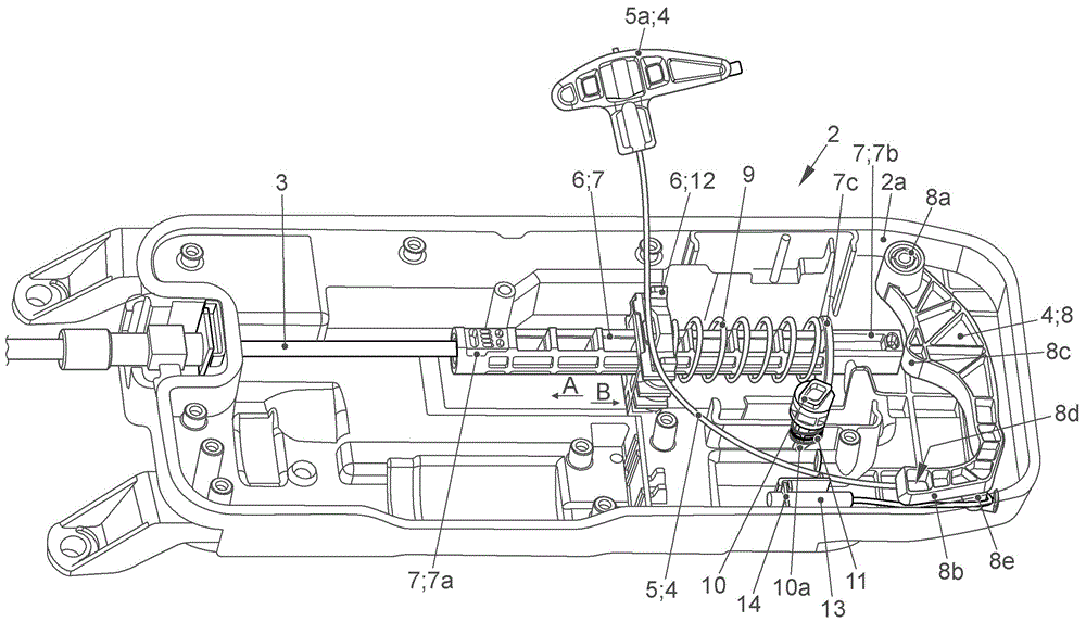
图1以非常简化的示意图示出根椐本发明的设备的总图示,该设备带有紧急操纵机构以及还有尤其为了正常运行而与驻车锁执行器有效地连接的拉压操纵绳索、尤其鲍登拉线,所述紧急操纵机构尤其用于紧急运行和/或停用机动车的变速器中的驻车锁,所述拉压操纵绳索用于操纵车辆的变速器中的锁止元件,FIG. 1 shows in a very simplified schematic diagram a general representation of a device according to the invention with an emergency actuation mechanism and also a tension and compression actuation cable, which is operatively connected, in particular for normal operation, to the parking lock actuator, In particular a Bowden cable for emergency activation and/or deactivation of a parking lock in a transmission of a motor vehicle, the tension and compression actuation cable for actuating a locking element in a transmission of a vehicle,
图2a,b以放大图示出图1的根据本发明的设备,尤其在紧急操纵机构未操纵的情况下带有驻车锁执行器的壳体(参见图2a),以及在紧急操纵机构被操纵的情况下带有经由操纵钮固定的操纵杠杆(参见图2b),2a, b show the device according to the invention of FIG. 1 in an enlarged view, in particular the housing with the parking lock actuator (see FIG. 2a) when the emergency actuation mechanism is not actuated, and when the emergency actuation mechanism is actuated. In the case of manipulation with a manipulation lever fixed via the manipulation knob (see Figure 2b),
图3以示意图示出图2的驻车锁执行器,但在没有上部壳体半部以及没有电动马达的驱动装置的图示情况下示出,但带有用于操纵锁止元件的驱动机构的图示,即带有推杆元件和支座元件以及弹簧元件的图示,其中,紧急操纵机构在此不被操纵,FIG. 3 shows the parking lock actuator of FIG. 2 in a schematic diagram, but without the upper housing half and without the illustration of the drive of the electric motor, but with the drive mechanism for actuating the locking element illustration, i.e. illustration with push rod element and abutment element and spring element, wherein the emergency actuation mechanism is not actuated here,
图4示出图2的根据本发明的设备,尤其在没有上部壳体部分以及没有电动马达的驱动装置的图示的情况下示出驻车锁执行器,但带有用于操纵锁止元件的驱动机构的图示,即带有推杆元件和支座元件以及弹簧元件的图示,其中,紧急操纵机构被操纵,以及FIG. 4 shows the device according to the invention of FIG. 2 , in particular the parking lock actuator without the upper housing part and without representation of the drive of the electric motor, but with a drive for actuating the locking element. Illustration of the drive mechanism, i.e. with push rod element and abutment element and spring element, wherein the emergency operating mechanism is actuated, and
图5以示意图示出根据本发明的设备,尤其在没有上部壳体部分以及没有电动马达的驱动装置的图示的情况下示出驻车锁执行器,但带有用于操纵锁止元件的驱动机构的图示,即带有推杆元件和支座元件以及弹簧元件的图示,带有已操纵的紧急操纵机构,其中,在此紧急操纵机构在该位置中可脱开地固定,尤其驻车锁在此持久地停用。5 shows a schematic diagram of the device according to the invention, in particular the parking lock actuator without the upper housing part and without representation of the drive of the electric motor, but with a drive for actuating the locking element The diagram of the mechanism, that is to say with the push rod element and the support element and the spring element, with the actuated emergency actuation mechanism, wherein the emergency actuation mechanism is fixed releasably in this position, in particular The lock is permanently deactivated here.
具体实施方式Detailed ways
图1至5至少部分地示出用于操纵在此未详细示出的车辆的在此未详细示出的变速器的在此未详细示出的驻车锁的设备1。设备1尤其用于操纵机动车的自动变速器的驻车锁。1 to 5 show at least partially a device 1 for actuating a parking lock (not shown in detail) of a transmission (not shown in detail) of a vehicle (not shown in detail here). The device 1 is used in particular for actuating a parking lock of an automatic transmission of a motor vehicle.
在图1至5中尤其示出驻车锁执行器2,该驻车锁执行器具有壳体2a。在图3至5中,尤其未示出壳体2a的上部壳体部分,以便可见地示出部件的工作原理。In particular, FIGS. 1 to 5 show a
借助于驻车锁执行器2,经由拉压操纵绳索3,尤其经由鲍登拉线3a,将未示出的锁止元件运动到和/或相应地带到锁定位置中,以用于有效地激活变速器的驻车锁,或者将锁止元件运动到和/或相应地带到解锁位置中,以用于有效地停用变速器的驻车锁。再次换言之,借助于拉压操纵绳索3能够激活/能够停用或能够相应地操纵机动车的变速器中的在此未详细示出的驻车锁。With the aid of the
此外,设置和/或存在有紧急操纵机构4,借助于该紧急操纵机构-在相应操纵的情况下-能够将锁止元件运动到和/或带到解锁位置中,以用于停用驻车锁。当驻车锁执行器2的电操控和/或电运行失灵时和/或尤其当用户想实现车辆的运动-在驻车锁尚激活的情况下-时、即当用户想手动地停用经激活的驻车锁时,则这尤其是必要的和/或有意义的。Furthermore, an
紧急操纵机构4具有至少一个拉绳元件5,其中,当紧急操纵机构4由用户操纵并且在拉绳元件5处施加拉力时,则能够将锁止元件运动到和/或带到其解锁位置中,以用于停用驻车锁。The
此时,开头提及的缺点首先通过如下方式避免,即,拉绳元件5在功能上有效地如此与驻车锁执行器2的驱动机构6连接,从而在相应操纵拉绳元件5的情况下于是借助于驻车锁执行器2的驱动机构6能够将锁止元件运动到和/或带到解锁位置中。由于在此此时紧急操纵机构4和驻车锁执行器2以一种方式在功能上彼此有效地联结,从而经由驻车锁执行器2的在正常运行时也使用的驱动机构6在操纵紧急操纵机构4时此时也能够将锁止元件带到解锁位置中,因此可减少用于实现用于操纵驻车锁的设备1的部件的数量,尤其也可减少用于实现紧急操纵机构4的部件的数量。由此节省了相应的成本,荻得了另外的优点,其下面还要更详细阐述:In this case, the disadvantages mentioned at the outset are firstly avoided in that the
在图1、2a和2b中,示出基本上带有完整的壳体2a的驻车锁执行器2。在图3至5中,以放大图示出驻车锁执行器2,但没有上部壳体半部,从而在壳体2a内的相应的部件显而易见。在此,示出驻车锁执行器2的驱动机构6,但未详尽示出马达的驱动装置、尤其未详尽示出电动马达的驱动装置。驻车锁执行器2的驱动机构6为了锁止元件的运动和/或定位而具有可运动地布置的推杆元件7。推杆元件7可运动地支承在壳体2a中。此外,驱动机构6具有支座元件12,该支座元件同样可运动地支承。尤其地,在此未示出的电动马达的驱动装置直接地或间接地使支座元件12运动。通过所述未示出的电动马达的驱动装置,支座元件12能够尤其沿着推杆元件7的纵向轴线部分地运动。支座元件12具有未详细标明的凹口,推杆元件7延伸穿过所述凹口,就如由图3至5显而易见的那样,并且推杆元件7可运动地支承在所述凹口中。推杆元件7的左边的第一端部区域7a与拉压操纵绳索3有效地连接。因而,经由推杆元件7的相应运动能够操纵拉压操纵绳索3并且能够相应地使锁止元件在变速器中运动和/或定位,如上文已经描述的。在正常运行中在电动马达地操控驻车锁执行器2时发生的支座元件12的运动尤其在图3中通过在那的箭头a和b示出。支座元件12因而可沿推杆元件7的纵向轴线的方向向左或向右运动。In FIGS. 1 , 2 a and 2 b a
支座元件12此时至少部分地在功能上有效地与推杆元件7联结。一方面,支座元件12能够经由至少一个在此未详细标明的且在图中不可看出的止挡部与推杆元件7联结,并且另一方面经由在图3至5中所示出的弹簧元件与推杆元件7联结。The
在驻车锁执行器2的正常运行中,即在电运行中,支座元件12为了将锁止元件带到其解锁位置中而在图3中向左根据箭头3驶动并且然后经由相应的止挡部在此带动推杆元件7向左。以此将锁止元件带到其解锁位置中,因为支座元件12然后也使推杆元件7向左运动。此外,在驻车锁执行器2的正常运行中,为了将锁止元件带到其锁定位置中,支座元件在图3中向右跟据箭头6移动。支座元件12然后克服弹簧元件9的弹簧力向右运动,其中,经由弹簧元件9与推杆元件7的联结(因为图3中所示的弹簧元件9的右端部贴靠在推杆元件7的凸肩7c处),那么同样经由相应的力加载然后使推杆元件7向右移动。由此,那么锁止元件借助于相应一起运动的拉压操纵绳索3转移或运动到其锁定位置中。During normal operation of the
可电运行的驻车锁执行器2因而具有用于锁止元件的运动和/或定位的驱动机构6,并且驱动机构6具有与支座元件12有效地联结且可运动地布置的推杆元件7。The electrically operable
如尤其图1也清楚所示,为了操纵锁止元件,设置有拉压操纵绳索3、尤其鲍登拉线3a,其中,拉压操纵绳索3尤其与第一端部区域7a、即在此与推杆元件7的在图中左边示出的端部区域7a直接地或间接地(在此尤其直接地)有效地联结。换言之,推杆元件7,如在此在图3至5中所示,使拉压操纵绳索3向左运动以用于停用驻车锁或者向右运动以用于激活驻车锁。经由推杆元件7的相应运动使锁止元件相应地一起运动到解锁位置或锁定位置中。下面此时尤其可详细阐述紧急操纵机构4的工作原理:As is also clearly shown in FIG. 1 , in order to actuate the locking element, a tension-
如此时尤其由图3至5变得清楚,拉绳元件5直接地或间接地、尤其在此间接地与推杆元件7、尤其与推杆元件7的第二端部区域76有效地联结和/或连接。为此,在功能上在推杆元件7的第二端部区域7b与拉绳元件5之间可摆动地和/或可运动地布置有操纵杠杆8。操纵杠杆8尤其在图3至5中在驻车锁执行器2的此处敞开地示出的壳体2a中的右边可看出。As becomes clear in particular from FIGS. 3 to 5 , the
图3至5示出,操纵杠杆8的第一端部8a以铰接的方式可摆动地铰接,而操纵杠杆8的第二端部8b或与第一端部8a相对而置的端部区域与拉绳元件5有效地连接。此外,操纵杠杆8尤其具有隆起形的区段8c用于接触推杆元件1的第二端部区域7b。3 to 5 show that the
图3至5尤其清楚示出,操纵杠杆8的隆起形的区段8c基本上尤其始终持久地与推杆元件7的第二端部区域7b处于接触或即使在摆动的情况下也与其处于接触。FIGS. 3 to 5 show particularly clearly that the bead-shaped
弹簧元件9此时布置和/或构造成使得推杆元件7经由弹簧元件9被如此加载力,使得锁止元件在推杆元件1进行沿弹簧元件9的力加载的方向所引起的运动的情况下那么能够运动到和/或带到其锁定位置中。换言之,如图3中所示,推杆元件7被向右移动或是向右移动的,因此锁止元件在此处在图3中所示出的该位置中那么位于其锁定位置中,驻车锁是激活的。在此,弹簧元件9布置在壳体2a的支座元件12与推杆元件7的凸肩7c之间。支座元件12具有未详细标明的用于可运动地支承推杆元件7的凹口,如已经阐述的。图3至5尤其也清楚示出,支座元件12在一侧上与弹簧元件9的左边的端部接触,其中,这在图中未详尽示出,尤其在支座元件12的另一侧上,支座元件12能够被带到与布置在推杆元件7上的止挡部有效地接触。The
如果此时如图4中所示紧急操纵机构4的拉绳元件5以拉力来操纵,尤其当用户在拉绳元件5的把手5a处进行牵拉或相应地操纵把手5a并且拉向自己,则操纵杠杆8沿顺时针方向围绕其第一端部8a相应地摆动。其隆起形的区域8c使推杆元件7克服弹簧元件9的弹簧力移动,其中,经由此那么能够将锁止元件运动到和/或带到其解锁位置中。换言之,图4示出停用的驻车锁的状态。对于推杆元件7向左移动的这种情况,推杆元件7的止挡部尤其也与支座元件12脱离接触。支座元件12那么尤其停留在其于图3中所示出的位置中。或再次换言之,推杆元件7克服弹簧元件9的弹簧力的移动(尤其从图3中所示的位置进一步向左)对于推杆元件7无问题地实现。由此,驻车锁那么在紧急运行中也相应地被停用。If the
如果此时拉绳元件5的把手5a就如图4中在经牵拉的状态下所示再次被释放,则在将拉力施加在拉绳元件5处之后,并且在推杆元件7的相应运动(从图3向图4)之后,此时拉力不再施加到拉绳元件5上,尤其当拉绳元件5的把手5a被释放时,则弹簧元件9的弹簧力将力加载沿相应的方向施加到推杆元件7上,从而推杆元件7由于弹簧元件9的力加载而从左向右移动,即运动返回到图3中所示出的位置中。If at this time the
换言之,操纵杠杆8从图4中所示出的位置沿逆时针方向摆动到图3中所示出的位置中。这具有以下效果,即,锁止元件再次运动返回到和/或相应地带到其在图3中所示出的锁定位置中。换言之,在紧急操纵机构4被操纵之后或在拉绳元件5被牵拉之后,再次释放把手5a,驻车锁再次自动激活。In other words, the
在设备1的一种非常优选的在此示出的实施形式中,此时在相应操纵紧急操纵机构4之后,操纵杠杆8能够可脱开地固定在其克服弹簧力使推杆元件7移动的位置中、即当锁止元件具有其解锁位置时。这在图4和5中在总关联下示出。如果操纵杠杆8相应地可脱开地固定,则由此推杆元件7也固定在相应的定位中,从而锁止元件运动到解锁位置中并且也停留在该解锁位置中。为了可脱开地固定操纵杠杆8,此时设置和/或存在有操纵钮10。In a very preferred embodiment of the device 1 shown here, after corresponding actuation of the
如尤其由图2至5变得清楚,操纵钮10具有销状的区域10a,其中,销状的区域10a能够被引入到操纵杠杆8的凹口8d中,以用于固定操纵杠杆8。As becomes clear in particular from FIGS. 2 to 5 , the actuating
在图4中,示出操纵杠杆8的未固定的位置,操纵钮10、尤其也克服经由另一(第二)弹簧元件11施加的弹簧力而向上移动。在此,操纵钮10相应地支承在驻车锁执行器2的壳体2a的尤其上部的壳体半部中。操纵钮10的销状的区域10a能够克服所述另一弹簧元件11的弹簧力被至少部分地引入到操纵杠杆8的凹口8d中,就如图5中所示,当紧急操纵机构4相应地被操纵并且操纵杠杆8如图5中所示地沿顺时针方向相应地摆动到在那示出的位置中时。In FIG. 4 , the unfixed position of the
图5示出通过操纵钮10的对操纵杠杆8的可脱开的固定。如果此时在图5中的图示中施加有施加到拉绳元件5上的拉力、尤其此时重复的拉力,则操纵钮10的销状的区域10a与操纵杠杆8的凹口8d由于弹簧元件11的作用的弹簧力而脱离接合、尤其自动地脱离接合。由于在此作用的力而作用在操纵钮10的销状的区域10a与操纵杠杆8的凹口8d之间的力配合和/或形状配合在这种情况下于是被取消,从而弹簧元件11的弹簧力可相应地作用并且使操纵钮10移动返回(尤其向上压)到图4中所示出的位置中。换言之,经由拉绳元件5也可脱开或可取消操纵杠杆8的图5中所示出的经固定的位置,从而那么锁止元件能够运动到和/或带到其锁定位置中,尤其那么操纵杠杆8从图5中所示的位置沿逆时针方向运动返回或能运动返回到图3中所示的位置。FIG. 5 shows the releasable fastening of the
在图3至5中所示出的优选的实施形式中,紧急操纵机构4或拉绳元件5以滑轮组的方式构造或实现滑轮组原理。这可在下面简短地详细阐述:In the preferred embodiment shown in FIGS. 3 to 5 , the
拉绳元件5的与拉绳元件5的把手5a相对而置的端部固定布置在驻车锁执行器2的壳体2a处。尤其地,在拉绳元件5的相应端部处设置或存在有套筒元件13,该套筒元件具有周向的凸肩14,该凸肩形状配合地置入到壳体2a的未详细标明的凹口中。如由图3至5进一步显而易见的,操纵杠杆8具有在此在图3至5中所示尤其向下伸的突起部8e,其中,拉绳元件5那么围绕突起部8e引导,以便实现用于拉绳元件5或用于紧急操纵机构4的滑轮组原理,以用于使操纵杠杆8运动。突起部8e可尤其如由图3至5显而易见的那样也借助于侧向错开的栓形成凹口/槽和/或具有缝口,拉绳元件5可穿入在所述凹口/槽中或穿入到所述缝口中。尤其地,拉绳元件5也可类似带地构造和/或实施,如图2a和2b中示意性示出的。The end of the pull-
由图3至5变得清楚,拉绳元件5以一个端部固定在壳体2a处并且滑动地支承在突起部8e处、尤其在实现于操纵杠杆8的相应端部区域处的槽中,以便如上所述地实现滑轮组原理。在把手5a处牵拉的用户或驾驶员因此最终仅须以“一半力”进行牵拉,以便使操纵杠杆8相应地摆动,与当拉绳元件在没有实现滑轮组原理的情况下布置在操纵杠杆的端部区域处时相比。As becomes clear from FIGS. 3 to 5 , the
因而,利用在此示出的根据本发明的设备1获得相应的优点并且相应地避免开头提及的缺点。图3至5示出或应说明驻车锁执行器2的紧急运行。在此在图1至5中所示出的驻车锁执行器2能够电动马达地和/或机电地运行,为此相应的电动马达的驱动装置设置在壳体2a内,但所述电动马达的驱动装置在此未详细示出。经由相应的电动马达的驱动装置,支座元件12在正常运行中、即在电运行中沿推杆元件7的纵向轴线方向驶动,由此将变速器中的锁止元件带到解锁位置或锁定位置中、即经由由此引起的推杆元件7的运动带到解锁位置或锁定位置中。在紧急运行中,当尤其停电时,支座元件12基本上固定或停止在特定的位置中。紧急运行那么经由紧急操纵机构4实现,尤其经由拉绳元件5和把手5a和其他相应的部件实现。紧急操纵机构4集成到驻车锁执行器2中。尤其地,在此处所示出的非常优选的实施形式中,拉绳元件5在功能上有效地与驱动机构6联结、尤其在此间接地经由操纵杠杆8联结,该驱动机构包括推杆元件7和支座元件12。可节省大量部件,因为驻车锁执行器2的驱动机构6的在正常运行中所使用的部件此时也可一起用于紧急操纵、尤其用于紧急解锁。Corresponding advantages are thus obtained with the device 1 according to the invention shown here, and the disadvantages mentioned at the outset are correspondingly avoided. 3 to 5 show or should explain the emergency operation of
附图标记列表:List of reference signs:
1 设备1 device
2 驻车锁执行器2 Park lock actuator
2a 壳体2a Shell
3 拉压操纵绳索3 Pull and press the steering rope
3a 鲍登拉线3a Bowden cable
4 紧急操纵机构4 Emergency operating mechanism
5 绳索牵拉元件5 Rope pulling element
5a 把手5a handle
6 驱动机构6 drive mechanism
7 推杆元件7 push rod element
7a 第一端部区域7a First end region
7b 第二端部区域7b Second end region
7c 凸肩7c Shoulder
8 操纵杠杆8 levers
8a 第一端部8a first end
8b 第二端部8b second end
8c 隆起形的区域8c Bump-shaped area
8d 凹口8d notch
8e 突起部8e protrusion
9 (第一)弹簧元件9 (first) spring element
10 操纵钮10 joystick
10a 销状的区域10a Pin-shaped area
11 (第二)弹簧元件11 (second) spring element
12 支座元件12 Support elements
13 套筒元件13 sleeve element
14 凸肩。14 Shoulders.
Claims (27)
Applications Claiming Priority (2)
| Application Number | Priority Date | Filing Date | Title |
|---|---|---|---|
| DE102019217395.0A DE102019217395A1 (en) | 2019-11-11 | 2019-11-11 | Device for actuating a parking lock of a transmission of a vehicle, in particular an automatic transmission of a motor vehicle |
| DE102019217395.0 | 2019-11-11 |
Publications (2)
| Publication Number | Publication Date |
|---|---|
| CN112780767A CN112780767A (en) | 2021-05-11 |
| CN112780767B true CN112780767B (en) | 2023-03-14 |
Family
ID=72801421
Family Applications (1)
| Application Number | Title | Priority Date | Filing Date |
|---|---|---|---|
| CN202011253094.5A Active CN112780767B (en) | 2019-11-11 | 2020-11-11 | Device for actuating a parking lock of a vehicle transmission, in particular an automatic motor vehicle transmission |
Country Status (3)
| Country | Link |
|---|---|
| EP (1) | EP3819524B1 (en) |
| CN (1) | CN112780767B (en) |
| DE (1) | DE102019217395A1 (en) |
Citations (9)
| Publication number | Priority date | Publication date | Assignee | Title |
|---|---|---|---|---|
| DE4447512A1 (en) * | 1994-06-24 | 1996-03-07 | Bayerische Motoren Werke Ag | Gear selector for motor vehicle automatic transmission |
| EP1199232A2 (en) * | 2000-10-19 | 2002-04-24 | Deere & Company | Control device for the parking lock of an motor vehicle |
| DE10105637A1 (en) * | 2001-02-08 | 2002-08-29 | Volkswagen Ag | Parking lock has main actuation lever via which spring storage device, actuating drive and locking device are connected to or can be brought into interaction with actuating element |
| CN101981358A (en) * | 2008-03-27 | 2011-02-23 | Zf腓特烈港股份公司 | Park lock system for automatic transmission |
| CN102197248A (en) * | 2008-10-29 | 2011-09-21 | Zf腓特烈斯哈芬股份公司 | Control element for a parking lock |
| DE102010053505A1 (en) * | 2010-12-04 | 2012-06-06 | Volkswagen Ag | Device for shift by wire actuation of parking lock integrated in speed change gear of motor car, has ratchet pawl of parking lock transferred from parking lock position into another parking lock position in control position |
| CN105114622A (en) * | 2015-09-15 | 2015-12-02 | 重庆长安汽车股份有限公司 | Parking locking mechanism for automatic transmissions |
| DE102016223551A1 (en) * | 2016-11-28 | 2018-05-30 | Zf Friedrichshafen Ag | Safety unit for setting a predetermined position of a component of a transmission and method for operating the safety unit |
| CN109073078A (en) * | 2016-04-21 | 2018-12-21 | 屈斯特控股有限责任公司 | The equipment and motor vehicle equipped with the equipment of actuator and the parking lock for introducing automatic speed changer for vehicle with the actuator |
Family Cites Families (3)
| Publication number | Priority date | Publication date | Assignee | Title |
|---|---|---|---|---|
| DE4317257C1 (en) * | 1993-05-24 | 1994-05-05 | Bayerische Motoren Werke Ag | Failsafe parking brake for automatic transmission - has manual override to release parking brake if hydraulics fail |
| DE102016116692B4 (en) * | 2016-09-07 | 2018-09-20 | Küster Holding GmbH | Device for actuating a parking brake in an automatic transmission of a motor vehicle |
| DE102016223557A1 (en) * | 2016-11-28 | 2018-05-30 | Zf Friedrichshafen Ag | Unlocking device for detecting at least one position of a drive unit in or in the region of a slider unit for a vehicle and method for sensing at least one position of a drive unit in or in the region of a slider unit of an unlocking device of a vehicle |
-
2019
- 2019-11-11 DE DE102019217395.0A patent/DE102019217395A1/en not_active Withdrawn
-
2020
- 2020-10-07 EP EP20200628.4A patent/EP3819524B1/en active Active
- 2020-11-11 CN CN202011253094.5A patent/CN112780767B/en active Active
Patent Citations (9)
| Publication number | Priority date | Publication date | Assignee | Title |
|---|---|---|---|---|
| DE4447512A1 (en) * | 1994-06-24 | 1996-03-07 | Bayerische Motoren Werke Ag | Gear selector for motor vehicle automatic transmission |
| EP1199232A2 (en) * | 2000-10-19 | 2002-04-24 | Deere & Company | Control device for the parking lock of an motor vehicle |
| DE10105637A1 (en) * | 2001-02-08 | 2002-08-29 | Volkswagen Ag | Parking lock has main actuation lever via which spring storage device, actuating drive and locking device are connected to or can be brought into interaction with actuating element |
| CN101981358A (en) * | 2008-03-27 | 2011-02-23 | Zf腓特烈港股份公司 | Park lock system for automatic transmission |
| CN102197248A (en) * | 2008-10-29 | 2011-09-21 | Zf腓特烈斯哈芬股份公司 | Control element for a parking lock |
| DE102010053505A1 (en) * | 2010-12-04 | 2012-06-06 | Volkswagen Ag | Device for shift by wire actuation of parking lock integrated in speed change gear of motor car, has ratchet pawl of parking lock transferred from parking lock position into another parking lock position in control position |
| CN105114622A (en) * | 2015-09-15 | 2015-12-02 | 重庆长安汽车股份有限公司 | Parking locking mechanism for automatic transmissions |
| CN109073078A (en) * | 2016-04-21 | 2018-12-21 | 屈斯特控股有限责任公司 | The equipment and motor vehicle equipped with the equipment of actuator and the parking lock for introducing automatic speed changer for vehicle with the actuator |
| DE102016223551A1 (en) * | 2016-11-28 | 2018-05-30 | Zf Friedrichshafen Ag | Safety unit for setting a predetermined position of a component of a transmission and method for operating the safety unit |
Also Published As
| Publication number | Publication date |
|---|---|
| EP3819524B1 (en) | 2022-08-31 |
| DE102019217395A1 (en) | 2021-05-12 |
| EP3819524A1 (en) | 2021-05-12 |
| CN112780767A (en) | 2021-05-11 |
Similar Documents
| Publication | Publication Date | Title |
|---|---|---|
| JP5417427B2 (en) | Parking lock system for automatic transmission | |
| ES2367208T3 (en) | OPERATING DEVICE WITH SELECTOR LEVER ACTUATOR. | |
| JP5897312B2 (en) | Parking brake system | |
| JPH0732899A (en) | Car parking / locking mechanism | |
| EP0878366A2 (en) | Park-position interlock system | |
| US5025901A (en) | Shift lever apparatus for automatic transmission | |
| JPH0361763A (en) | Safety device in controlling automatic transmission of automobile | |
| JP2024546662A (en) | Automobile locks, particularly automobile door locks | |
| JP4204230B2 (en) | Shift device with shift lever for automatic transmission of automobile | |
| CN112780767B (en) | Device for actuating a parking lock of a vehicle transmission, in particular an automatic motor vehicle transmission | |
| US20050160859A1 (en) | Device to switch over a mechanical shifting means | |
| JP7542254B2 (en) | Accelerator pedal misoperation prevention mechanism | |
| US11193579B2 (en) | Vehicle shifter having a toggle cam with neutral lock | |
| JPS6128094Y2 (en) | ||
| JP2016011108A (en) | Shift lock device | |
| JPH05288266A (en) | Vehicle parking lock release device | |
| JP4022596B2 (en) | Shift lever device | |
| JPH0425407Y2 (en) | ||
| KR100380932B1 (en) | Foot Pedal Parking Brake System of One Touch Way | |
| KR100887827B1 (en) | Shift lever device of an automatic transmission for an automobile | |
| US4042084A (en) | Vehicle clutch control assembly | |
| JPH10311306A (en) | Lock device | |
| KR200142975Y1 (en) | Foot Parking Brake | |
| JPH05296339A (en) | Fail-safe mechanism of automatic transmission | |
| JP7218999B2 (en) | Operation lever device for automatic transmission |
Legal Events
| Date | Code | Title | Description |
|---|---|---|---|
| PB01 | Publication | ||
| PB01 | Publication | ||
| SE01 | Entry into force of request for substantive examination | ||
| SE01 | Entry into force of request for substantive examination | ||
| GR01 | Patent grant | ||
| GR01 | Patent grant |