Drawings
The above and/or additional aspects and advantages of the present invention will become apparent and readily appreciated from the following description of the embodiments, taken in conjunction with the accompanying drawings of which:
fig. 1 is a schematic structural diagram of a piezoelectric fan according to an embodiment of the present invention, in which a swing blade assembly is integrally formed as a liquid-cooled heat dissipation module;
fig. 2 is a schematic structural diagram of a piezoelectric fan according to an embodiment of the present invention, in which a vane assembly is formed as a plurality of liquid-cooled heat dissipation modules;
FIG. 3 is a schematic structural diagram of a piezoelectric fan according to an embodiment of the present invention, in which a swing region is connected to a heat source;
FIG. 4 is a schematic structural diagram of a piezoelectric fan according to an embodiment of the present invention, in which a swing region is connected to a heat source and a swing blade assembly is formed as a plurality of liquid-cooled heat dissipation modules;
FIG. 5 is a schematic structural diagram of a piezoelectric fan according to an embodiment of the present invention, in which a continuous fixed-area continuous oscillating-area single piezoelectric actuator unit;
FIG. 6 is a schematic structural diagram of a piezoelectric fan according to an embodiment of the present invention, in which a continuous fixed-area continuous oscillating-area multi-piezoelectric actuator unit;
FIG. 7 is a schematic structural diagram of a piezoelectric fan according to an embodiment of the present invention, in which a continuous fixed-area discrete oscillating-area single piezoelectric actuator unit;
FIG. 8 is a schematic structural diagram of a piezoelectric fan according to an embodiment of the present invention, in which a continuous fixed-area discrete oscillating-area multi-piezoelectric actuator unit;
FIG. 9 is a schematic structural diagram of a piezoelectric fan according to an embodiment of the present invention, in which a discrete fixed-area continuous type oscillating-area single piezoelectric actuating unit;
FIG. 10 is a schematic structural diagram of a piezoelectric fan according to an embodiment of the present invention, in which a discrete fixed-area continuous type oscillating-area multi-piezoelectric actuating unit;
FIG. 11 is a schematic structural diagram of a piezoelectric fan according to an embodiment of the present invention, wherein a discrete fixed-area discrete oscillating-area single piezoelectric actuator unit;
FIG. 12 is a schematic structural diagram of a piezoelectric fan according to an embodiment of the present invention, wherein a discrete fixed-area discrete oscillating-area single piezoelectric actuator unit;
FIG. 13 is a schematic structural diagram of a piezoelectric fan according to an embodiment of the invention, wherein the piezoelectric fan and a heat source are bonded by a discrete multi-bonding surface;
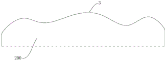
FIG. 14 is a schematic structural diagram of a heat source according to an embodiment of the invention, in which the bonding surface is a spatially curved surface;
fig. 15 is a schematic structural view of a heat source according to an embodiment of the invention, wherein the faying surface is at least one of a planar and curved spatial hybrid;
fig. 16 is a schematic structural diagram of a heat source according to an embodiment of the invention, in which the faying surface is a space-polyhedral type combined by a plurality of planes;
FIG. 17 is a schematic structural view of a piezoelectric fan in which the oscillating region of the oscillating vane assembly extends beyond the piezoelectric actuating unit and is connected to the oscillating member, according to an embodiment of the present invention;
FIG. 18 is a schematic structural view of a piezoelectric fan in which a piezoelectric actuator unit is attached to a swinging member according to an embodiment of the present invention;
FIG. 19 is a schematic structural diagram of a piezoelectric fan in which a single liquid-cooled heat sink module or a plurality of liquid-cooled heat sink modules are disposed on one side of a flap according to an embodiment of the present invention;
FIG. 20 is a schematic structural diagram of a piezoelectric fan according to an embodiment of the present invention, in which a plurality of liquid-cooled heat dissipation modules are disposed on two sides of a swing blade;
FIG. 21 is a schematic structural diagram of a piezoelectric fan according to an embodiment of the present invention, in which a plurality of liquid-cooled heat dissipation modules are disposed on two sides of a swing blade;
FIG. 22 is a schematic structural diagram of a piezoelectric fan in which a single liquid-cooled heat sink module or a plurality of liquid-cooled heat sink modules are disposed on one side of a flap according to an embodiment of the present invention;
FIG. 23 is a schematic structural diagram of a piezoelectric fan according to an embodiment of the present invention, in which a plurality of liquid-cooled heat dissipation modules are disposed on two sides of a swing blade;
FIG. 24 is a schematic structural diagram of a piezoelectric fan according to an embodiment of the present invention, in which a plurality of liquid-cooled heat dissipation modules are arranged on two sides of a swing blade in another form;
FIG. 25 is a schematic structural view of a power pump according to an embodiment of the present invention;
FIG. 26 is a schematic diagram of a power pump according to an embodiment of the present invention, wherein the power pump is in a suction state;
FIG. 27 is a schematic diagram of a power pump configuration according to an embodiment of the present invention, wherein the power pump is in a scheduled state;
fig. 28 is a schematic structural view of a vibration plate according to an embodiment of the present invention, wherein the vibration plate is an integral vibration plate;
fig. 29 is a schematic structural view of a vibration plate according to an embodiment of the present invention, wherein the vibration plate is a split type vibration plate;
FIG. 30 is a schematic structural view of a power pump according to an embodiment of the present invention, wherein the power pump is a dual chamber pump;
FIG. 31 is a schematic structural view of a power pump according to an embodiment of the present invention, the power pump being a combination dual chamber pump;
FIG. 32 is a schematic structural view of a power valve according to an embodiment of the invention;
FIG. 33 is a schematic diagram of a liquid-cooled heat dissipation module according to an embodiment of the invention, wherein the liquid-cooled heat dissipation module employs a through-slot channel;
FIG. 34 is a schematic diagram of a liquid-cooled heat dissipation module according to an embodiment of the invention, wherein the liquid-cooled heat dissipation module employs a recessed channel;
FIG. 35 is a schematic diagram of a liquid-cooled heat dissipation module according to an embodiment of the invention, wherein the liquid-cooled heat dissipation module employs a mixing tank channel;
FIG. 36 is a schematic structural diagram of a liquid-cooled heat dissipation module according to an embodiment of the present invention, wherein the liquid-cooled heat dissipation module employs a multi-layer basic flow channel mixing flow channel;
fig. 37 is a schematic structural diagram of a liquid-cooled heat dissipation module according to an embodiment of the invention, wherein the liquid-cooled heat dissipation module is in a flexible bending state.
Reference numerals:
the piezoelectric fan (100) is provided with a piezoelectric fan,
the oscillating vane assembly 10, the fixed area 101, the oscillating area 102,
a swinging blade 1, a fixed part 11 and a swinging part 12;
a liquid cooling heat dissipation module 2, a flow channel device 21, a flow channel 21a, a flow channel layer 211, a flow guiding slot 2111,
panel layer 212, panel 2121; penetrates through the groove layer 2122, the runner groove plate 2123, the liquid inlet hole 213, the liquid outlet hole 214, the liquid inlet 215,
the pump includes a power pump 22, a pump chamber 22a, a pump body 221, a liquid inlet 222, a liquid outlet 223, a vibration plate 224, an excitation unit 2241, a vibration plate 2242, a connecting portion 2243, a first fluid valve 225, a second fluid valve 226, a power valve 227, a vibration portion 2271, and a valve inlet 2272; a valve outlet 2273;
the cover plate (23) is provided with,
the adhesive surface (3) is provided with a plurality of adhesive layers,
the oscillating piece (4) is provided with a swinging piece,
the piezoelectric actuation unit 20 is provided with a piezoelectric actuator,
a heat source 200.
Detailed Description
The technical solutions in the embodiments of the present invention will be clearly and completely described below with reference to the drawings in the embodiments of the present invention, and it is obvious that the described embodiments are only a part of the embodiments of the present invention, and not all of the embodiments. All other embodiments, which can be derived by a person skilled in the art from the embodiments given herein without making any creative effort, shall fall within the protection scope of the present invention.
A piezoelectric fan 100 according to an embodiment of the present invention is described below with reference to fig. 1 to 36.
The piezoelectric fan 100 according to an embodiment of the present invention may include: the oscillating vane assembly 10 and the piezoelectric actuating unit 20, specifically, referring to fig. 1 and 2, the oscillating vane assembly 10 is connected with a heat source 200, the oscillating vane assembly 10 comprises a liquid cooling heat dissipation module 2 formed into a laminated structure, the oscillating vane assembly 10 is provided with a fixed area 101 and an oscillating area 102, the fixed area 101 is fixed, the oscillating area 102 is suspended and can oscillate back and forth, the piezoelectric actuating unit 20 is connected with the oscillating vane assembly 10, and the piezoelectric actuating unit 20 provides power for the oscillation of the oscillating area 102.
Optionally, the external periodic signal frequency is the first-order resonance frequency of the piezoelectric fan 100 or a value near the first-order resonance frequency, so that the reciprocating displacement of the oscillating region 102 can be increased, during the high-frequency oscillation of the oscillating region 102, ambient air is beaten, so that the ambient air flow velocity is accelerated, and vortices and turbulent flows are formed locally, thereby strong convective heat transfer is formed between the thermal boundary layer on the surface of the oscillating blade assembly 10 and the ambient air, the air quickly sweeps away heat on the surface of the oscillating blade assembly 10, the continuous reciprocating oscillation of the oscillating region 102 pushes the hot air far away to take away the heat, and meanwhile, the heat of the heat source 200 is continuously transferred to the oscillating blade assembly 10, so that efficient heat dissipation is formed.
In view of this, according to the piezoelectric fan 100 of the embodiment of the present invention, by providing the flap assembly 10 and the piezoelectric actuation unit 20 including the liquid-cooling heat dissipation module 2, when the piezoelectric fan 100 works, the heat of the heat source 200 can be rapidly and uniformly dispersed on the flap assembly 10 under the combined action of the heat transfer of the flap assembly 10 and the working medium circulation of the liquid-cooling heat dissipation loop of the liquid-cooling heat dissipation module 2, and meanwhile, the piezoelectric actuation unit 20 is excited by an external periodic electrical signal to generate vibration to drive the swing region 102 to swing back and forth, so as to improve the heat dissipation efficiency.
In some embodiments of the present invention, referring to fig. 1 to 13, the swing blade assembly 10 further includes a swing blade 1, and at least one of the swing blade 1 and the liquid-cooled heat dissipation module 2 has an abutting surface 3 formed thereon, the abutting surface 3 being adapted to cooperate with the heat source 200, and the abutting surface 3 being formed in a single continuous type or the abutting surface 3 being formed in a discrete type. For example, the swing blade 1 is tightly attached to the heat source 200, the fixing portion 11 of the swing blade 1 may be tightly attached to the heat source 200, as shown in fig. 1-2, the swinging portion 12 of the swing blade 1 may be tightly attached to the heat source 200, as shown in fig. 3-4, or the fixing portion 11 and the swinging portion 12 of the swing blade 1 may be simultaneously tightly attached to a continuous or discrete heat source.
Optionally, the liquid-cooled heat dissipation module 2 is connected to the swing blade 1, and at least one of the liquid-cooled heat dissipation module 2 and the swing blade 1 is connected to the heat source 200, in other words, the liquid-cooled heat dissipation module 2 is connected to the heat source 200, or the swing blade 1 is connected to the heat source 200, or both the liquid-cooled heat dissipation module 2 and the swing blade 1 are connected to the heat source 200. For example, as shown in fig. 19 to 24, the liquid-cooled heat dissipation module 2 may be disposed on at least one side in the thickness direction of the swing blade 1.
Referring to fig. 19-24, the piezoelectric actuator unit 20 is connected to the swing vane 1 and/or the liquid-cooled heat dissipation module 2, in other words, the piezoelectric actuator unit 20 may be connected to the swing vane 1, or the piezoelectric actuator unit 20 may be connected to the liquid-cooled heat dissipation module 2, or the piezoelectric actuator unit 20 may be connected to both the swing vane 1 and the liquid-cooled heat dissipation module 2, and the piezoelectric actuator unit 20 provides power for the swing of the swing region 102. For example, the piezoelectric actuator unit 20 includes at least one piezoelectric wafer, and the piezoelectric actuator unit 20 is excited by an external periodic electrical signal to generate vibration, so as to drive the swing region 102 to swing back and forth.
It can be understood that the configuration of the swing blade assembly 10 has various configurations according to the different configurations of the formed fixed area 101 and swing area 102, specifically, the configuration of the fixed area 101 may be a continuous single fixed area 101, or a discrete multiple fixed area 101, the configuration of the swing area 102 may be a continuous single swing area 102, or a discrete multiple swing area 102, and the configuration of the swing blade assembly 10 is any combination of the above-mentioned configurations of the fixed area 101 and swing area 102, as shown in fig. 5-12.
In some embodiments of the present invention, referring to fig. 1, the oscillating vane 1 and the liquid-cooled heat dissipation module 2 are a single piece. For example, the liquid-cooled heat dissipation module 2 may even be formed as the swing blade 1. It can be understood that, the structure of an organic whole not only can guarantee the structure, the stable performance of pendulum leaf 1 and liquid cooling heat dissipation module 2 to convenient shaping, make simply, saved unnecessary assembly part and connection process moreover, improved the assembly efficiency of pendulum leaf 1 and liquid cooling heat dissipation module 2 greatly, guarantee the reliability that pendulum leaf 1 and liquid cooling heat dissipation module 2 are connected, moreover, the bulk strength and the stability of the structure of an organic whole formation are higher, it is more convenient to assemble, the life-span is longer. Of course, the invention is not limited to this, and the swing blade 1 and the liquid-cooled heat dissipation module 2 may also be a separate member.
In some embodiments of the present invention, the liquid-cooled heat dissipation module 2 is stacked on at least one side of the swing blade 1 in the thickness direction. In other words, the liquid-cooled heat dissipation module 2 is stacked on one side in the thickness direction of the swing blade 1, or the liquid-cooled heat dissipation module 2 is stacked on both sides in the thickness direction of the swing blade 1. Therefore, the structure is simple, the attachment area between the liquid cooling heat dissipation module 2 and the swing blade 1 is increased, and the heat transfer efficiency is improved.
In some embodiments of the invention, the swing area 102 and the fixed area 101 are a unitary piece. It can be understood that the structure of the integrated piece not only can ensure the structural stability and performance stability of the swing area 102 and the fixed area 101, but also is convenient to form and simple to manufacture, and redundant assembling parts and connecting processes are omitted, so that the assembling efficiency of the swing area 102 and the fixed area 101 is greatly improved, the reliability of connection of the swing area 102 and the fixed area 101 is ensured, and moreover, the integral structure is high in overall strength and stability, more convenient to assemble and longer in service life. Of course, the present invention is not limited thereto, and the swing region 102 and the fixing region 101 may be a single piece, for example, the swing region 102 and the fixing region 101 may be connected together by welding or other means. For example, the swing blade assembly 10 may be formed in a planar sheet, an arcuate sheet, or any combination thereof.
In some examples of the present invention, the swing blade 1 and/or the liquid-cooled heat dissipation module 2 are made of a heat conductive metal or a polymer material or other heat conductive materials, and it should be noted that, when the swing blade is made of a metal material, heat can be more rapidly and more uniformly spread on the swing blade assembly 10, but the process difficulty is correspondingly increased, the overall compliance is reduced, and the liquid-cooled heat dissipation module is suitable for a scene where the heating surface of the heat source 200 is relatively regular; when the heat dissipation structure is made of a polymer material, heat is quickly and uniformly spread on the swing blade assembly 10 through the liquid cooling heat dissipation module 2, the process difficulty is low, the cost is low, the flexible patch form is easily formed integrally, and the heat dissipation structure is suitable for heat dissipation of a heat source 200 with a complex heating surface.
Optionally, at least one of the swing blade 1 and the liquid-cooled heat dissipation module 2 is provided with a heat conduction film, and the heat conduction coefficient of the heat conduction film is higher than that of the swing blade 1 and the liquid-cooled heat dissipation module 2. For example, the thermally conductive film may be a super-conductive metal film, a graphite film, or a graphene film. Therefore, the heat transfer on the swinging blade 1 and/or the liquid cooling heat dissipation module 2 can be accelerated.
In some embodiments of the present invention, at least one of the swing blade 1 and the liquid-cooled heat dissipation module 2 is provided with a concave-convex portion, wherein the concave-convex portion may be formed as a protrusion or a groove, or at least one of the swing blade 1 and the liquid-cooled heat dissipation module 2 is provided with a heat conduction fin, thereby further improving heat transfer and heat dissipation effects.
For example, the liquid cooling heat dissipation module 2 and/or the surface of the swing blade 1 contacting the air form a plurality of protrusions or depressions, which increases the contact area between the swing blade 1 and the air and accelerates the heat dissipation, or the liquid cooling heat dissipation module 2 and/or the surface of the swing blade 1 contacting the air are integrally formed or fixedly connected with a plurality of heat conduction fins, which further improves the heat transfer and heat dissipation effects.
In some embodiments of the present invention, referring to fig. 1 and 2, at least a portion of the piezoelectric actuation unit 20 is disposed on the swing region 102, for example, the swing blade 1 includes a fixed portion 11 and a swing portion 12, the fixed portion 11 corresponds to the fixed region 101, the swing portion 12 corresponds to the swing region 102, at least a portion of the piezoelectric actuation unit 20 is disposed on the swing portion 12 of the swing blade 1, or at least a portion of the piezoelectric actuation unit 20 is disposed on the liquid-cooled heat dissipation module 2 attached to the swing blade 1, and the attachment position corresponds to the swing portion 12 of the swing blade 1. Thereby, it is advantageous to ensure the reliability of the operation of the piezoelectric actuation unit 20.
It should be noted that the number of the piezoelectric actuating units 20 may be one or more, a single piezoelectric actuating unit 20 is disposed on one side of the swing blade assembly 10, and a plurality of piezoelectric actuating units 20 are disposed on one side or both sides of the swing blade assembly 10; a single piezoelectric actuation unit 20 may power a single oscillation region 102 alone, or a single piezoelectric actuation unit 20 may power multiple oscillation regions 102 simultaneously, or multiple piezoelectric actuation units 20 may power a single oscillation region 102 simultaneously. When a plurality of swing regions 102 exist simultaneously in the structure, and each swing region 102 is powered by a single piezoelectric actuating unit 20, the swing directions of two adjacent swing regions 102 can be the same or opposite, or have a certain phase difference, as shown in fig. 8 and 12.
In some embodiments of the present invention, referring to fig. 31-37, the liquid-cooled heat dissipation module 2 includes a flow passage device 21 and a power pump 22, the flow passage device 21 has a flow passage 21a therein, and the power pump 22 is in communication with the flow passage device 21 to drive the flow of the cooling working medium in the flow passage 21 a. For example, the power pump 22 and the flow channel 21a are both formed as a patch structure, and it can be understood that the power pump 22 is communicated with the flow channel device 21 to drive the cooling working medium in the flow channel 21a to flow, so that the heat exchange efficiency of the cooling working medium in the flow channel 21a can be improved, and the heat dissipation capability of the liquid cooling heat dissipation module 2 can be ensured.
In some embodiments of the present invention, and as illustrated with reference to FIGS. 33-35, the power pump 22 includes: the cooling device comprises a pump body 221, a vibration plate 224, a first fluid valve 225 and a second fluid valve 226, wherein the pump body 221 is provided with at least one pump cavity 22a, the pump body 221 is further provided with a liquid inlet 222 and a liquid outlet 223 which are communicated with the pump cavity 22a, the liquid inlet 222 and the liquid outlet 223 are used for being communicated with a flow channel 21a, the vibration plate 224 covers the pump cavity 22a and is connected with the pump body 221, the vibration plate 224 can generate reciprocating vibration under the driving of an alternating signal so as to change the volume of the pump cavity 22a, the first fluid valve 225 is arranged at the liquid inlet 222, the first fluid valve 225 is used for controlling the unidirectional flow of cooling working medium in the flow channel 21a into the pump cavity 22a, the second fluid valve 226 is arranged at the liquid outlet 223, and the second fluid valve 226 is used for controlling the unidirectional.
See fig. 26 and 27 for a specific working principle: the volume of the pump chamber 22a is changed in size by the reciprocating motion of the vibration plate 224 and the fluid is directionally flowed in cooperation with the first fluid valve 225 and the second fluid valve 226. The operation of the power pump 22 can be divided into two processes of suction and discharge. When the vibration plate 224 bends upward, the volume of the pump cavity 22a increases, the pressure in the cavity decreases, and under the action of the pressure difference between two sides, the first fluid valve 225 at the liquid inlet 222 is opened, the second fluid valve 226 at the liquid outlet 223 is closed, and the fluid flows into the pump cavity 22a from the fluid valve at the liquid inlet 222, so that the fluid suction is completed; when the vibration plate 224 bends downwards, the volume of the pump cavity 22a is reduced, the pressure in the cavity is increased, the second fluid valve 226 at the liquid outlet 223 is opened, the first fluid valve 225 at the liquid inlet 222 is closed, the fluid discharging process is completed, when a continuous alternating signal is applied to the vibration plate 224, the power pump 22 completes continuous suction and discharge, and the unidirectional fluid flow is realized, so that the structure is simple and convenient to realize.
As shown in fig. 33-36, in some embodiments of the present invention, flow conduit device 21 comprises: the flow channel layer 211, the flow channel layer 211 includes the base plate and the guiding gutter 2111 formed on the base plate; the panel layer 212, the panel layer 212 includes at least one panel 2121, the panel 2121 covers the diversion trench 2111, a flow channel 21a is defined between the diversion trench 2111 and the panel layer 212, and the panel layer 212 is provided with a liquid inlet hole 213 and a liquid outlet hole 214 which are suitable for being communicated with the power pump 22. Therefore, the power pump 22 is communicated with the flow passage device 21 to form a closed whole filled with working media, thereby being beneficial to ensuring the working reliability of the piezoelectric fan 100.
In some embodiments of the present invention, the panel layer 212 is provided with a liquid inlet 215 communicating with the flow passage 21a, and the liquid inlet 215 is sealed by the lid plate 23. Therefore, the liquid cooling heat dissipation module 2 is convenient to add cooling working media, and the reliable operation of the liquid cooling heat dissipation module 2 is guaranteed.
The specific structure of the piezoelectric fan 100 according to the embodiment of the present invention will be described in detail with reference to fig. 1 to 36. It is to be understood, of course, that the following description is intended to illustrate the invention and not to limit the invention.
Example one
Referring to fig. 1 to 12, a piezoelectric fan 100 provided in this embodiment includes a swing blade assembly 10 and a piezoelectric actuating unit 20 fixedly disposed on the swing blade assembly 10, where the swing blade assembly 10 is formed with at least one liquid-cooled heat dissipation module 2 and is of a laminated structure, the swing blade assembly 10 has a fixed region 101 and a swing region 102, and meanwhile, a joint surface 3 is formed on a surface of the swing blade assembly 10, the swing blade assembly 10 is tightly jointed with a heat source 200 through the joint surface 3, and the swing region 102 is suspended and can swing back and forth; the piezoelectric actuation unit 20 is disposed to the pendulum assembly 10 to power the oscillation of the oscillation region 102. When the piezoelectric fan is in work, the heat source 200 continuously generates heat, the heat source 200 and the swing blade assembly 10 are subjected to heat transfer through the binding surface 3, under the combined action of heat transfer of the swing blade assembly 10 and working medium circulation of a liquid cooling heat dissipation loop of the liquid cooling heat dissipation module 2, the heat of the heat source 200 can be rapidly and uniformly dispersed on the swing blade assembly 10, meanwhile, the piezoelectric actuation unit 20 is excited by an external periodic electric signal to generate vibration, so as to drive the swing area 102 to swing back and forth at the frequency of the periodic signal, preferably, the frequency of the external periodic signal is a value near a first-order resonance frequency or a first-order resonance frequency of the piezoelectric fan 100, so that the displacement of the back and forth swing of the swing area 102 is increased, and in the high-frequency swing process of the swing area 102, the surrounding air is flapped, so that the surrounding air flow rate is accelerated, and a vortex and a turbulent flow are, the air quickly sweeps away the heat on the surface of the oscillating vane assembly 10, the continuous reciprocating oscillation of the oscillating area 102 pushes the hot air far away to take away the heat, and meanwhile, the heat of the heat source 200 is continuously transferred to the oscillating vane assembly 10, so that efficient heat dissipation is realized.
The swing blade assembly 10 further comprises a swing blade 1, the swing blade 1 and the liquid cooling heat dissipation module 2 are an integrated piece, at least one of the swing blade 1 and the liquid cooling heat dissipation module 2 is provided with a bonding surface 3 suitable for being matched with the heat source 200, and the bonding surface 3 is formed into a single continuous type or the bonding surface 3 is formed into a discrete type. For example, the swing blade 1 is tightly attached to the heat source 200, the fixing portion 11 of the swing blade 1 may be tightly attached to the heat source 200, as shown in fig. 1-2, the swinging portion 12 of the swing blade 1 may be tightly attached to the heat source 200, as shown in fig. 3-4, or the fixing portion 11 and the swinging portion 12 of the swing blade 1 may be simultaneously tightly attached to a continuous or discrete heat source.
The structural form of the swing blade assembly 10 has various configurations according to the structural form of the formed fixed area 101 and the swing area 102.
Specifically, the fixed region 101 may be a continuous single fixed region 101 or a discrete multiple fixed region 101, the oscillating region 102 may be a continuous single oscillating region 102 or a discrete multiple oscillating region 102, and the configuration of the oscillating vane assembly 10 is any combination of the above-mentioned fixed region 101 and oscillating region 102, as shown in fig. 5 to 12.
It should be noted that the number of the piezoelectric actuating units 20 may be one or more, a single piezoelectric actuating unit 20 is disposed on one side of the swing blade assembly 10, and a plurality of piezoelectric actuating units 20 are disposed on one side or both sides of the swing blade assembly 10; a single piezoelectric actuation unit 20 may power a single oscillation region 102 alone, or a single piezoelectric actuation unit 20 may power multiple oscillation regions 102 simultaneously, or multiple piezoelectric actuation units 20 may power a single oscillation region 102 simultaneously. When a plurality of swing regions 102 exist simultaneously in the structure, and each swing region 102 is powered by a single piezoelectric actuating unit 20, the swing directions of two adjacent swing regions 102 can be the same or opposite, or have a certain phase difference, as shown in fig. 8 and 12.
Example two
As shown in fig. 13, the present embodiment has substantially the same structure as the first embodiment, except that the attachment surface 3 formed on the swing blade assembly 10 is a discrete multi-attachment surface, which is suitable for heat dissipation of discrete heat sources.
EXAMPLE III
As shown in fig. 14 to 16, the present embodiment has substantially the same structure as the first to second embodiments, except that the shape of the attachment surface 3 formed on the swing blade assembly 10 is a curved surface type, a spatial mixing type of at least one plane and a curved surface, or a multi-plane spatial multi-surface type.
It should be noted that the shape of the bonding surface 3 is not particularly limited, and the bonding surface 3 of the fixing region 101 is constructed in accordance with the geometry of the heat generating surface of the applicable target heat source 200 in order to facilitate the forming and to increase the bonding area as much as possible.
Example four
As shown in fig. 17 to 18, the present embodiment has substantially the same structure as the first to third embodiments, except that one or more swinging members 4 are fixedly connected to the swinging vane assembly 10 and/or the piezoelectric actuating unit 20, so as to increase the number and/or swinging length of the swinging regions 102, increase displacement, improve directional air volume, and improve heat dissipation effect.
EXAMPLE five
As shown in fig. 19 to 21, the present embodiment has substantially the same structure as the first to fourth embodiments, except that at least one single liquid-cooled heat dissipation module 2 is further fixedly disposed on the surface of the flap assembly 10, the single liquid-cooled heat dissipation module 2 is disposed on one side of the flap assembly 10, and the plurality of liquid-cooled heat dissipation modules 2 are disposed on one side or both sides of the flap assembly 10.
The single piezoelectric actuating unit 20 is partially or completely arranged on one side of the swing area 102 of the swing blade assembly 10 close to the fixed area 101 to provide power for the reciprocating bending swing of the swing area 102.
The binding surface 3 is formed on the swing blade 1 and/or on the liquid cooling heat dissipation module 2 fixedly arranged on the swing blade 1, the binding surface 3 is tightly bound with the heat source 200, and the form of the binding surface 3 can be a single continuous type or a plurality of discrete types.
EXAMPLE six
As shown in fig. 22 to 24, the present embodiment has substantially the same structure as the fifth embodiment, except that the swing blade 1 and the liquid-cooled heat dissipation module 2 are non-integrated members, the liquid-cooled heat dissipation module 2 is stacked on at least one side of the swing blade 1 in the thickness direction, a single liquid-cooled heat dissipation module 2 is disposed on one side of the swing blade 1, and a plurality of liquid-cooled heat dissipation modules 2 are disposed on one side or both sides of the swing blade 1.
The binding surface 3 is formed on the swing blade 1 and/or on the liquid cooling heat dissipation module 2 fixedly arranged on the swing blade 1, the binding surface 3 is tightly bound with the heat source 200, and the form of the binding surface 3 can be a single continuous type or a plurality of discrete types.
EXAMPLE seven
As shown in fig. 25 to 37, the present embodiment is mainly designed for the liquid-cooled heat dissipation module 2 to form different types of the swing blade assembly 10.
Specifically, as shown in fig. 25, the liquid-cooled heat dissipation module 2 of the present embodiment includes a flow channel device 21 and at least one power pump 22, the flow channel device 21 has a flow channel 21a therein to form a heat dissipation loop, the power pump 22 is communicated with the flow channel device 21 to drive a cooling working medium in the flow channel 21a to flow, and both the power pump 22 and the flow channel 21a are formed as a patch structure.
In the present embodiment, the power pump 22 includes: the pump comprises a pump body 221, a vibration plate 224, a first fluid valve 225 and a second fluid valve 226, wherein the pump body 221 is provided with at least one pump cavity 22a, the pump body 221 is further provided with a liquid inlet 222 and a liquid outlet 223 communicated with the pump cavity 22a, the liquid inlet 222 and the liquid outlet 223 are used for being communicated with the flow channel 21a, the vibration plate 224 covers the pump cavity 22a and is connected with the pump body 221, and the vibration plate 224 can generate reciprocating vibration under the driving of an alternating signal so as to change the volume of the pump cavity 22 a. A first fluid valve 225 is arranged at the fluid inlet 222, the first fluid valve 225 is used for controlling the unidirectional flow of the cooling working medium in the flow passage 21a into the pump cavity 22a, a second fluid valve 226 is arranged at the fluid outlet 223, and the second fluid valve 226 is used for controlling the unidirectional flow of the cooling working medium in the pump cavity 22a into the flow passage 21a, see fig. 26 and 27, and the specific working principle is that: the reciprocating motion of the vibration plate 224 changes the volume of the pump chamber 22a and cooperates with the fluid valve to direct the flow of fluid. The operation of the power pump 22 can be divided into two processes of suction and discharge. When the vibration plate 224 bends upward, the volume of the pump cavity 22a increases, the pressure in the cavity decreases, and under the action of the pressure difference between two sides, the first fluid valve 225 at the liquid inlet 222 is opened, the second fluid valve 226 at the liquid outlet 223 is closed, and the fluid flows into the pump cavity 22a from the first fluid valve 225 at the liquid inlet 222, so that the fluid suction is completed; when the vibration plate 224 bends downwards, the volume of the pump cavity 22a is reduced, the pressure in the cavity is increased, the second fluid valve 226 at the liquid outlet 223 is opened, the first fluid valve 225 at the liquid inlet 222 is closed, the fluid discharging process is completed, when a continuous alternating signal is applied to the vibration plate 224, the power pump 22 completes continuous suction and discharge, and the unidirectional fluid flow is realized, so that the structure is simple and convenient to realize.
Specifically, the vibrating plate 224 of the present embodiment may be configured in an integral type or a separate type, as shown in fig. 28, the excitation unit 2241 and the vibrating plate 2242 of the integral type vibrating plate 224 are closely attached to each other, the excitation unit 2241 drives the vibrating plate 2242 to generate vertical reciprocating deformation, as shown in fig. 29, the excitation unit 2241 and the vibrating plate 2242 of the separate type vibrating plate 224 are connected by a connecting portion 2243, specifically, one end of the excitation unit 2241 is fixed and the other end is hinged to the vibrating plate 2242 by the connecting portion 2243, a periodic ac signal is applied to the excitation unit 2241, so that one end of the excitation unit 2241 connected to the vibrating plate 2242 is periodically deformed upward and downward, the vibrating plate 2242 is driven to generate vertical reciprocating deformation, and the volume of the pump chamber 22a is periodically changed.
It should be noted that the power pump 22 in this embodiment may be a single chamber pump or a multi-chamber pump, such as an integral dual chamber pump as shown in fig. 30 or a combination dual chamber pump as shown in fig. 31.
The power pump 22 of this embodiment is preferably a miniature piezoelectric diaphragm pump, and the miniature piezoelectric diaphragm pump can be highly integrated with the heat transfer and heat dissipation functional module and the flow channel 21a, need not to set up heat exchanger (liquid reserve tank) and external pipeline alone, and compact structure adapts to the user demand in narrow and small heat dissipation space.
The first fluid valve 225 and the second fluid valve 226 in this embodiment are preferably cantilever beam type check valves, but other valve bodies can be used, such as the power valve 227 shown in fig. 32, and the power valve 227 can have a valve inlet 2272, a valve outlet 2273 and a vibrating portion 2271, as long as the unidirectional flow of the fluid can be controlled, and the valve is not limited thereto. Of course, the fluid valve may be designed as one or more valves according to different control modes, and is not limited thereto.
As shown in fig. 33 to 36, the flow path device 21 of the present embodiment includes: the flow channel layer 211, the flow channel layer 211 includes the base plate and the guiding gutter 2111 formed on the base plate; the panel layer 212, the panel layer 212 includes at least one panel 2121, the panel 2121 covers the diversion trench 2111, a flow channel 21a is defined between the diversion trench 2111 and the panel layer 212, and the panel layer 212 is provided with a liquid inlet hole 213 and a liquid outlet hole 214 which are suitable for being communicated with the power pump 22. Therefore, the power pump 22 is communicated with the flow passage device 21 to form a closed whole filled with working media, thereby being beneficial to ensuring the working reliability of the piezoelectric fan 100.
It should be noted that, in this embodiment, at least one flow guide slot 2111 is provided, when the flow guide slots 2111 are multiple, the multiple flow guide slots 2111 may be mutually communicated and configured with a group of liquid-cooled heat dissipation flow paths, the multiple flow guide slots 2111 may also be mutually independent, and each flow guide slot 2111 is configured with a group of liquid-cooled heat dissipation flow paths, as long as the heat dissipation effect can be achieved, and the specific layout manner is not limited.
According to an embodiment of the flow conduit device 21 of the present invention, referring to fig. 33, the flow conduit 2111 is a through-groove, the panel layer 212 comprises a first panel and a second panel, the flow conduit layer 211 is arranged between the first panel and the second panel, and the first panel, the second panel and the through-groove cooperate to form the flow conduit device 21. Specifically, the flow channel device 21 is a basic flow channel formed by sequentially laminating and bonding three thin plates, and the first panel, the flow channel layer 211 and the second panel are respectively a flow channel upper plate, a through groove layer 2122 and a flow channel lower plate, wherein the flow channel upper plate is provided with a liquid inlet hole 213, a liquid outlet hole 214, a liquid injection port 215 and a cover plate 23; the penetrating groove layer 2122 is provided with a communicated groove which is formed completely in a penetrating way; the lower runner plate is a thin plate without any characteristics. The working medium is injected into the flow passage 21a through the injection port 215, and then is sealed by the cover plate 23, and the power pump 22 is communicated with the flow passage 21a to form a closed whole filled with the working medium.
In another embodiment of flow conduit device 21 according to the present invention, referring to fig. 34, channels 2111 are recessed and panel layer 212 includes a face plate 2121, and face plate 2121 and the recessed channel cooperate to form flow conduit 21 a. The flow channel device 21 is a basic flow channel formed by sequentially laminating and bonding a face plate 2121 and a flow channel layer 211, the face plate 2121 and the flow channel layer 211 are respectively a flow channel upper plate and a flow channel groove plate 2123, wherein the flow channel upper plate is provided with a liquid inlet hole 213, a liquid outlet hole 214, a liquid injection port 215 and a cover plate 23, and the flow channel groove plate 2123 is provided with a groove with a certain depth and communicated with each other. The working medium is injected into the flow passage 21a through the injection port 215, and then is sealed by the cover plate 23, and the power pump 22 is communicated with the flow passage device 21 to form a closed whole filled with the working medium.
Of course, in this embodiment, two kinds of flow passage devices 21 may be combined to perform the flow guiding function. As shown in fig. 35, the mixing tank flow path 21a is a basic flow path 21a formed by sequentially laminating and bonding three thin plates. The three layers of thin plates are respectively a flow channel upper plate, a through groove layer 2122 and a flow channel groove plate 2123, wherein the flow channel upper plate is provided with a liquid inlet hole 213, a liquid outlet hole 214, a liquid injection port 215 and a cover plate 23, one side close to the through groove layer 2122 can be provided with a communicated groove with a certain depth or not, the shape of the communicated groove is consistent with that of the groove of the through groove layer 2122, and the through groove layer 2122 is provided with a communicated groove formed by complete penetration; the flow channel plate 2123 is provided with a continuous groove having a certain depth, and the shape of the groove is the same as that of a groove penetrating through the groove layer 2122.
Of course, as shown in fig. 36, the flow path 21a may be formed by laying out a plurality of layers of basic flow paths.
The substrate and/or the panel 2121 in this embodiment is a thin plate or a thin film, the thin plate or the thin film may be a metal material, a polymer material, or a composite material, preferably a polymer material, such as PP, PPs, or PET, and when the polymer material is preferentially used in a communication device or an electromagnetic product, the interference and shielding of communication signals and electromagnetic signals can be effectively avoided, and the application environment of current 5G signal transmission is matched, compared with the use of a metal material, the development trend and the design concept of light weight of a product are better fitted, and meanwhile, the form of a heat dissipation surface is easily processed, such as a flange or a fin is arranged on the heat dissipation surface, so that the heat dissipation area is increased, and thus the heat dissipation performance comparable to or even better than that of a metal heat sink.
Preferably, the power pump 22 has external dimensions not exceeding 40mm x 10mm (length x width x thickness).
Preferably, the equivalent diameter of the flow channel 21a is 10 μm to 3 mm.
As can be seen from the above, both the power pump 22 and the flow passage 21a of the present embodiment can be designed as a laminated structure, thereby contributing to the compact design of the product.
Example eight:
as shown in fig. 37, the flow path device 21 of the liquid-cooled heat dissipation module 2 of the present embodiment is formed in a flexible laminated structure.
Specifically, when the piezoelectric fan 100 works, the heat source 200 continuously generates heat, the heat source 200 and the flap 1 and/or the liquid cooling module 2 fixedly arranged on the flap 1 are subjected to heat transfer through the attachment surface 3, the heat reaching the flap 1 and/or the liquid cooling module 2 fixedly arranged on the flap 1 and near the heat source 200 is rapidly dispersed to the surface of the flap 1 and/or the liquid cooling module 2 fixedly arranged on the flap 1 under the combined action of the heat transfer of the flap 1 and/or the liquid cooling module 2 structure body fixedly arranged on the flap 1 and the working medium circulation of the liquid cooling heat dissipation loop, the piezoelectric actuation unit 20 generates vibration under the excitation of periodic electric signals, the swinging region 102 reciprocates in high frequency under the action of the piezoelectric actuation unit 20 to flap the surrounding air, so that the surrounding air flow velocity is accelerated, and vortex and turbulence is formed locally, therefore, strong convection heat transfer is formed between the heat boundary layer on the surface of the swing blade 1 and/or the liquid cooling heat dissipation module 2 fixedly arranged on the swing blade 1 and the ambient air, the air quickly sweeps away the heat on the surface of the swing blade 1 and/or the liquid cooling heat dissipation module 2 fixedly arranged on the swing blade 1, the continuous reciprocating swing of the swing area 102 pushes the hot air to a far place to take away the heat, and meanwhile, the heat of the heat source 200 is continuously transferred to the swing blade 1 and/or the liquid cooling heat dissipation module 2 fixedly arranged on the swing blade 1, so that efficient heat dissipation is formed.
In summary, compared with the prior art, the piezoelectric fan 100 of the embodiment of the invention has the following beneficial effects:
(1) the swinging vane 1, the liquid cooling heat dissipation module 2 and the piezoelectric actuating unit 20 are all formed into a laminated structure, the swinging vane 1 and/or the liquid cooling heat dissipation module 2 fixedly arranged on the swinging vane 1 are tightly attached to the heat source 200 through the attaching surface 3, the structural form that the heat dissipation assembly and the heat source 200 are separately arranged in the past is changed, the structure is more compact, the occupied space is small, and the heat dissipation requirement of a narrow space can be met.
(2) The number and the shape of the binding surfaces 3 are matched with those of heat source heating surfaces, so that the heat source heat-insulating material is suitable for continuous heat sources and discrete heat sources, is suitable for plane heat sources, curved surface heat sources, body heat sources and the like, and has a wide application range.
(3) The liquid cooling heat dissipation module 2 and the swing blade 1 are integrally formed or fixedly arranged on the swing blade 1, so that heat can be rapidly and uniformly dispersed from the heat source 200 to the surface of the swing blade 1 and/or the liquid cooling heat dissipation module 2, meanwhile, the swing area 102 swings at high frequency to flap surrounding air to form vortex and turbulent flow, convection heat exchange between a heat boundary layer and the surrounding air is enhanced, the hot air is pushed far, the heat is taken away, and the heat dissipation efficiency is high.
(4) The piezoelectric actuating unit 20 has low energy consumption, works at high frequency, has low noise or no noise, and is energy-saving and environment-friendly.
Other constructions and operations of the piezoelectric fan 100 according to embodiments of the present invention are known to those of ordinary skill in the art and will not be described in detail herein.
In the description of the present invention, it is to be understood that the terms "central," "longitudinal," "lateral," "length," "width," "thickness," "upper," "lower," "front," "rear," "left," "right," "vertical," "horizontal," "top," "bottom," "inner," "outer," "clockwise," "counterclockwise," "axial," "radial," "circumferential," and the like are used in the orientations and positional relationships indicated in the drawings for convenience in describing the invention and to simplify the description, and are not intended to indicate or imply that the referenced device or element must have a particular orientation, be constructed and operated in a particular orientation, and are not to be considered limiting of the invention.
In the description herein, references to the description of the term "one embodiment," "some embodiments," "an illustrative embodiment," "an example," "a specific example," or "some examples" or the like mean that a particular feature, structure, material, or characteristic described in connection with the embodiment or example is included in at least one embodiment or example of the invention. In this specification, the schematic representations of the terms used above do not necessarily refer to the same embodiment or example. Furthermore, the particular features, structures, materials, or characteristics described may be combined in any suitable manner in any one or more embodiments or examples.
While embodiments of the invention have been shown and described, it will be understood by those of ordinary skill in the art that: various changes, modifications, substitutions and alterations can be made to the embodiments without departing from the principles and spirit of the invention, the scope of which is defined by the claims and their equivalents.