This application claims priority from U.S. provisional patent application No. 62/684,381, filed 2018, 6/13, the contents of which are incorporated herein by reference in their entirety.
Disclosure of Invention
In one aspect, the present invention provides an intracardiac device comprising: an elongate tubular body having a lumen extending between two open ends; an axial flow pump positioned within the lumen; at least one valve positioned at each open end; and a centrifugal pump having an inlet and an outlet fluidly connected to the lumen of the main body by a first tube and a second tube, and a side port fluidly connected to the at least one cleaning port by a third tube.
In one embodiment, the apparatus further comprises a wireless power system having a transmitter coil electrically connected to the battery, and an implantable receiver coil electrically connected to the axial flow pump, each valve, and the centrifugal pump.
In one embodiment, the body has a collapsible scaffolding structure with a membrane covering therein. In one embodiment, wherein the membrane covering is a pericardium, a polymer, or a combination thereof.
In one embodiment, an axial flow pump comprises: an elongated housing having a motor at a first end and an open second end; a rotor positioned within the housing between the first end and the second end, the rotor coupled to the motor; at least one side inlet located on the housing and proximate to the rotor; and a diffuser located adjacent the open end.
In one embodiment, the rotor has a shaftless design comprising: a hollow, substantially cylindrical housing having a height, an inner diameter, an outer surface, an inner surface, and a long axis extending from two open ends; and at least one blade attached to the inner surface of the housing in a helical pattern, each blade having a pitch, a length extending from the inner surface of the housing, a thickness, and an angle relative to the inner surface of the housing; wherein the length of each vane is less than half the diameter of the housing.
In one embodiment, the rotor has a height of between about 15mm and 25mm and an inner diameter of between about 10mm and 30 mm. In one embodiment, the pitch of each blade is individually adjustable. In one embodiment, the housing is driven by a motor coupled to its outer surface, its inner surface, or the open end. In one embodiment, the housing further comprises an embedded magnet. In one embodiment, the housing is driven by an electromagnet or a rotating magnet.
In one embodiment, the at least one valve is selected from the group consisting of: stepper valves, clamps, iris valves, solenoid valves, memory alloy valves, diaphragm valves, balloon occluders, single leaf valves and multi-leaf valves.
In one embodiment, the apparatus further comprises at least one oxygen sensor, pH sensor, flow sensor, temperature sensor, and heart rate monitor. In one embodiment, the apparatus further comprises an implantable wireless receiver and an external controller configured to activate and regulate the axial pump, each valve, and the centrifugal pump.
In another aspect, the present invention provides a method of minimally invasive implantation, comprising the steps of: providing an intracardiac device of the present invention; forming a first hole in the subject's fossa ovalis bridging the right atrium and left atrium, and forming a second hole in the subject's sinotubular junction (sinotubular junction) bridging the right atrium and aorta; and inserting an intracardiac device into the subject's heart such that the first end is secured to the first aperture and the second end is secured to the second aperture, and the intracardiac device is placed in the right atrial appendage (right atrial appendage) to form a fluid pathway between the left atrium and the aorta.
In one embodiment, the first hole is formed by inserting a guidewire into the right atrium through the femoral or internal jugular vein and guiding the puncture needle and dilator to the fossa ovalis. In one embodiment, the second hole is formed by inserting a guidewire into the aorta through the carotid or femoral artery and guiding a puncture needle and dilator to the sinotubular junction.
In another aspect, the invention provides a method of sealing the device of the invention, comprising the step of closing each valve at both ends of the device.
In another aspect, the invention provides a method of cleaning the device of the invention, comprising the steps of: closing each valve at both ends of the device; activating the centrifugal pump; injecting a cleaning liquid into the first cleaning port; and drawing the used cleaning liquid from the second cleaning port.
In another aspect, the present invention provides a method of administering a therapeutic agent to a subject by means of the device of the present invention, comprising the steps of: activating the centrifugal pump; and injecting a therapeutic agent into the first cleaning port.
Drawings
The following detailed description of embodiments of the present invention can be better understood when read in conjunction with the appended drawings. It should be understood, however, that the invention is not limited to the precise arrangements and instrumentalities of the embodiments shown in the drawings.
Fig. 1 is a schematic diagram depicting an exemplary intracardiac device.
Fig. 2 depicts an axial pump component of an exemplary intracardiac device.
Fig. 3 depicts an exemplary fluid actuator compatible with axial pump components of an exemplary intracardiac device.
Figure 4 depicts the valve components of an exemplary intracardiac device that open and close.
Figure 5 depicts a number of alternative valve components of an exemplary intracardiac device.
Fig. 6 depicts a cleaning port component of an exemplary intracardiac device.
Fig. 7 depicts centrifugal pump components compatible with cleaning port components of an exemplary intracardiac device.
Fig. 8 depicts a flow chart of a method of inserting an exemplary intracardiac device.
Fig. 9A-9B illustrate insertion and positioning of an exemplary intracardiac device.
Fig. 10 depicts decompensation and recovery in class III heart failure, as well as the impact of therapy provided by an exemplary intracardiac device.
Fig. 11 depicts a collection of prototype centrifugal pumps compatible with cleaning port components.
Fig. 12 depicts a prototype centrifugal pump with a prototype magnetic coupling.
Fig. 13 depicts a prototype cleaning port and centrifugal pump connected to a controller and wireless power system.
Fig. 14 depicts experimental results testing the performance of the prototype centrifugal pump.
Fig. 15 depicts experimental results modeling fluid flow in a prototype centrifugal pump.
Fig. 16 depicts the structure of a prototype centrifugal pump.
Fig. 17 depicts the structure and arrangement of a prototype axial flow pump compatible with intracardiac devices.
Fig. 18 depicts experimental results testing the performance of prototype axial flow pumps under different operating conditions.
Fig. 19 depicts a prototype axial flow pump connected to a controller.
Fig. 20 depicts experimental results of testing the power requirements of prototype axial flow pumps of different sizes.
Fig. 21 depicts experimental results testing the performance of prototype axial flow pumps of different sizes under different operating conditions.
Figure 22 depicts a collection of prototype valves compatible with intracardiac devices.
Fig. 23 depicts an experimental setup combining a prototype cleaning port component with a valve component.
Fig. 24 depicts a prototype stepper valve with silicone cover.
Fig. 25 depicts a prototype gear-driven iris valve.
Fig. 26 depicts various prototype gearbox driven valves.
Fig. 27A-27C depict a prototype free-stroke power delivery system. Fig. 27A depicts a transmit coil (left) and a receive coil (right). Fig. 27B depicts a controller and transmitter. Fig. 27C depicts a receiver printed circuit board and a receiver coil encapsulated in polydimethylsiloxane.
Fig. 28 depicts an experimental setup of a prototype wireless power system in an animal model.
Fig. 29A and 29B depict experimental results of a prototype wireless power system in an animal model.
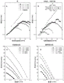
FIG. 30 depicts experimental results of flow rate and head pressure for fluid actuators at different vane lengths.
FIG. 31 depicts experimental results of flow rates and head pressures for fluid actuators at different vane thicknesses.
FIG. 32 depicts experimental results of flow rate and torque for fluid actuators at different blade pitches.
FIG. 33 depicts experimental results of flow rates of fluid actuators for different blade shapes.
Fig. 34 depicts experimental results of different fluid actuator heights versus flow rate.
Fig. 35 depicts experimental results of different fluid actuator diameters versus flow rate.
Fig. 36 depicts experimental results of fluid actuator diameters and minimum rotational speeds required to prevent backflow.
Fig. 37 depicts experimental results of different fluid actuator diameters versus flow rate and head pressure.
Fig. 38 depicts experimental results of different fluid actuator heights and diameters versus torque.
Fig. 39 depicts experimental results of different fluid actuator heights versus flow rate and head pressure.
Fig. 40 depicts a simulated flow profile of a fluid actuator having a height of 15mm and a diameter of 15mm actuated at 10000 RPM.
Fig. 41 depicts the relationship between flow rate and head pressure in a fluid actuator having a height of 15mm and a diameter of 15 mm.
FIG. 42 depicts a simulated flow profile of a fluid actuator having a height of 20mm and a diameter of 30mm actuated at 5000 RPM.
Fig. 43 depicts the relationship between flow rate and head pressure in a fluid actuator having a height of 20mm and a diameter of 30 mm.
Fig. 44A and 44B depict conceptual stages of impeller design. Fig. 44A depicts an initial design process inspired by avian heart valves. Fig. 44B depicts design parameters for adjusting pump performance. All corresponding parameters are labeled in the three-dimensional view of the impeller design.
Fig. 45 depicts the results of a parametric study to adjust volumetric flow. The initial impeller design is adjusted by changing design parameters to maximize volumetric flow. Unless otherwise stated under the simulation setup described in table 1, the initial values of the inner diameter (d), the spiral height (H), the spiral pitch (p), the blade length (l), the blade thickness (t), the guide blade angle (α), the number of blades (n), and the blade shape of 15mm, 26mm, 6.5mm, 1mm, 90 degrees, 3, and a rectangular (parallelogram) shape were used, respectively.
Fig. 46A to 46C depict calculation models and settings. (FIG. 46A) Mod 1: the final model is obtained by the initial design process for each parameter specified in fig. 44B. (FIG. 46B) Mod 2: the second model makes design modifications to Mod1 based on findings in the Mod1 analysis. A conical end for a smooth blood transition into the gap is achieved. The cut at the leading edge in Mod1 is replaced by a rounded edge to reduce hydraulic losses. The trailing edge is converted into a vertical cut. Among the key features added to Mod 2 is that the outboard grooves have the same wrap angle as the impeller vanes, which is expected to prevent backflow through the outer gap and increase overall pump efficiency. (FIG. 46C) geometric settings for pump evaluation in Ansys software.
Fig. 47A and 47B depict prototype impeller and pump designs.
Fig. 48A and 48B depict experimental pump performance curves and static efficiencies of the final computational model. Numerically determined head pressure (fig. 48A) and pump hydraulic efficiency (fig. 48B) are presented for comparison at different flow rates within three different pump speeds for Mod1 and within 15000RPM (5, 10, 20L/min) for Mod 2.Mod 2 results in a steeper pump curve. The best hydraulic efficiency point (BEP) is defined as the maximum value of each efficiency curve. Similar to ordinary blood pumps, it shows a tendency to have a higher maximum for higher pump speeds. The highest efficiency that can be achieved in the range of pump speeds studied is 10.95% at 20L/min.
Fig. 49A to 49D depict the results of flow field analysis on the final calculation model. The hydraulic power is shown on the final models Mod1 (fig. 49A, 49B) and Mod 2 (fig. 49C, 49D), which highlight the regions where hydraulic losses occur. For both models, the hydraulic losses found in the clearance between the bushing and the casing were negligible compared to the hydraulic losses on the blades (fig. 49A and 49C). FIGS. 49B and 49D show that below the optimal hydraulic efficiency point (BEP) (V < V) for 15000RPMbep) At the optimum hydraulic efficiency point (V ═ V)bep) And above the optimum hydraulic efficiency point (V > V)bep) The hydraulic power on the individual blades of each model evaluated at the pump flow rate. Since the impeller geometry is symmetrical, the distribution of hydraulic power can be assumed to be similar for the other two blades.
FIG. 50 depicts a graph showing shaft power generated by Mod1 and Mod 2. Shaft power is the integral of the hydraulic power depicted in fig. 48A and 48B, as a variable on the blade surface, which visualizes the efficiency of the flow guidance and highlights the areas where hydraulic losses occur.
Fig. 51A and 51B depict experimental results of studying flow fields and quantifying backflow. (FIG. 51A) when the pump flow rate (V) is lower than (V < V)bep) Where (V ═ V)bep) And is higher than (V > V)bep) Flow field in Mod1 for the optimal efficiency point of 12500 RPM. (FIG. 51B) quantization within Mod1 and Mod 2 is reflowed. The use of slots on the impeller bushing in Mod 2 significantly reduces the secondary clearance backflow compared to Mod 1.
Fig. 52A to 52C depict experimental results investigating the effect of inlet and outlet dimensions on flow rate. Fig. 52A has a large inlet and a large outlet, fig. 52B has a small inlet and a large outlet, and fig. 52C has a large inlet and a small outlet.
Fig. 53A and 53B depict pump performance curves for a small impeller (fig. 53A) and a large impeller (fig. 53B), respectively.
Fig. 54A-54C depict pressure-flow rate performance at different RPMs for three common auxiliary devices: HeartMate II (fig. 54A); HeartWare HVAD (fig. 54B); and HeartMate III (fig. 54C).
Fig. 55A-55C depict an exemplary prototype impeller. Fig. 55A depicts a wide impeller prototype and a narrow impeller prototype alongside an AAA battery for size comparison. Fig. 55B depicts a machined and 3D printed impeller prototype. Fig. 55C depicts a view of the opposite end of the impeller prototype in which the clear hole design is visible.
Detailed Description
The invention provides an intracardiac device and a method for implanting the same. Intracardiac devices have a collapsible stent design and include an axial flow pump to support cardiac function. The axial pump may feature an axial-free fluid actuator that reduces blood cell damage while increasing the efficiency of fluid delivery. Intracardiac devices include valves that can be closed to seal the implanted device from the subject's anatomy. The intracardiac device includes a cleaning system configured to introduce and circulate cleaning fluids and therapeutic agents to the implanted device. The intracardiac devices are powered and controlled wirelessly. Minimally invasive surgery may be used to implant the intracardiac device without the need for open heart surgery (open heart surgery).
Definition of
It is to be understood that the figures and descriptions of the present invention have been simplified to illustrate elements that are relevant for a clear understanding of the present invention, while eliminating, for purposes of clarity, many other elements that are commonly found in the art. One of ordinary skill in the art may recognize that other elements and/or steps are desirable and/or required in implementing the present invention. However, because such elements and steps are well known in the art, and because they do not facilitate a better understanding of the present invention, a discussion of such elements and steps is not provided herein. The disclosure herein is directed to all such variations and modifications to such elements and methods known to those skilled in the art.
Unless defined otherwise, all technical and scientific terms used herein have the same meaning as commonly understood by one of ordinary skill in the art to which this invention belongs. Any methods and materials similar or equivalent to those described herein can be used in the practice or testing of the present invention, and only exemplary methods and materials are described herein.
As used herein, each of the following terms has the meaning associated with the term in this section.
The articles "a" and "an" are used herein to refer to one or to more than one (i.e., to at least one) of the grammatical object of the article. For example, "an element" means one element or more than one element.
When referring to a measurable value such as an amount, duration, etc., the term "about" as used herein is intended to encompass variations of 20%, 10%, 5%, 1% and 0.1% from the specified value, as such variations are appropriate.
Throughout this disclosure, aspects of the present invention may be presented in a range format. It is to be understood that the description in range format is merely for convenience and brevity and should not be construed as an inflexible limitation on the scope of the invention. Accordingly, the description of a range should be considered to have specifically disclosed all the possible sub-ranges as well as individual numerical values within that range. For example, description of a range such as 1 to 6 should be considered to specifically disclose sub-ranges such as 1 to 3, 1 to 4, 1 to 5, 2 to 4, 2 to 6, 3 to 6, etc., as well as individual values within that range, e.g., 1, 2, 2.7, 3, 4, 5, 5.3, 6, and any whole or partial increments therein. Regardless of the width of the range.
Intracardiac device
The present invention provides an improved intracardiac device. Intracardiac devices may be implanted for cardiac support, for example in the case of ventricular failure. Intracardiac devices have a collapsible structure for minimally invasive implantation. In one aspect, an intracardiac device has an inflow valve and an outflow valve. Closing the inflow and outflow valves regulates flow and can seal the intracardiac device when not in use, extending the life of the device. In one aspect, an intracardiac device includes a cleaning system. The cleaning system includes an intake port and a centrifugal pump that enables the introduction and rapid circulation of cleaning fluid into the intracardiac device. Coupling the cleaning system with the inflow and outflow valves allows the device to be held while implanted without biological or chemical fouling (e.g., stenosis, intimal hyperplasia, encrustation, etc.). In one aspect, intracardiac devices include novel fluid actuators. The fluid actuator provides a shaftless design to drive larger amounts of fluid with less power and is less traumatic to cells and other structures that may be present in the fluid.
Referring now to fig. 1, an exemplary intracardiac device 100 is depicted. The intracardiac device 100 comprises: a substantially cylindrical stent body 102 having a lumen extending between two open ends, a valve 300 positioned at each open end, an axial flow pump 200 positioned between each valve 300, and a cleaning system 400 fluidly connected to the lumen. The stent body 102 may have a mesh or wire-like structure such that the stent body 102 may be folded into a narrow configuration for ease of insertion and expandability at the implantation site. In certain embodiments, the stent body 102 includes a covering that may have a biological (e.g., pericardium or engineered tissue scaffold) structure, an artificial (e.g., polymeric) structure, or a hybrid biological and artificial structure.
The various components of the apparatus 100, including each valve 300, axial flow pump 200, and cleaning system 400, may be powered by a receiving coil 104 that wirelessly receives electromagnetic energy from a transmitting coil 106 and a battery 108, and a power line 105. In certain embodiments, the device 100 further includes a wireless receiver and a controller 110 configured to communicate with the wireless receiver to activate and adjust each component of the device 100. For example, the controller 110 may be configured to wirelessly open and close each valve 300 to activate and regulate the speed of the axial flow pump 200 and activate the cleaning system 400. Prototype receive coils 104 and transmit coils 106 and experimental results are depicted in fig. 27A-29B.
Referring now to FIG. 2, an axial flow pump 200 is depicted in greater detail. The axial flow pump 200 includes a housing 201 attachable to a sheath 206. A motor 202 fits within the housing 201 and is attached to the rotor 204. The jacket 206 includes at least one inlet 208 and an outlet 210 and includes a diffuser 212 positioned adjacent the outlet 210. The at least one inlet 208 is configured to be positionable adjacent to the rotor 204 when the sheath 206 is attached to the housing 201. The rotor 204 is configured to be actuated by the motor 202 and draw fluid through the at least one inlet 208 so the fluid advances toward the outlet 210. The diffuser 212 directs the fluid toward the outlet 210 in a manner that reduces turbulence. Prototype axial flow pump 200 and experimental results are depicted in fig. 17-21.
In some embodiments, the axial pump 200 may alternatively employ the fluid actuator 500 shown in fig. 3. The fluid actuator 500 provides a shaftless design for actuating a fluid and includes a housing 502 having a plurality of blades 504. The housing 502 has a hollow, substantially cylindrical shape with a long axis, an open end, and outer and inner surfaces. Each vane 504 is attached to an inner surface of casing 502 and extends in a helical pattern from an opposite end of casing 502. The blades 504 are thus configured to actuate fluid by rotation of the housing 502 along its long axis. This rotation may be achieved by a mechanical connection to the motor, such as through an edge drive connection (fig. 47A) or an end drive connection (fig. 47B). The rotation may also be achieved by magnetic coupling with an external electromagnet or rotating magnet. Although the blade 504 is depicted as having a cross-sectional shape that is substantially parallelogram-like, it should be understood that the blade 504 may have any suitable cross-sectional shape, including rectangular, with rounded edges, with sharp edges, and the like.
The dimensions of actuator 500 may be adjusted to suit a particular application and include an inner diameter 506 and a height 508 of housing 502, and a pitch 510, a length 512, a thickness 514, and an angle 516 of blade 504. In certain embodiments, the height 508 may be between about 15mm and 25mm, with a greater height increasing the volumetric flow rate and head pressure. In certain embodiments, the inner diameter 506 may be between about 10mm and 30mm, with larger diameters increasing the volumetric flow rate and the head pressure. The pitch 510 may be described as a number of revolutions per unit height 508, and in certain embodiments may vary between about 0.2 to 1 revolution per 10mm, 15mm, and 25 mm. Thus, the optimal pitch 510 depends on the particular height 508, and generally a larger pitch reduces torque. In some embodiments, one or more blades 504 may have a variable pitch 510, wherein pitch 510 may be individually controlled to adjust torque and flow when actuator 500 is in motion. In certain embodiments, the length 512 may be between about 3mm and 8mm, with larger lengths increasing the volumetric flow rate and the head pressure. In certain embodiments, the thickness 514 may be between about 0.1mm and 2 mm. It is to be understood that the dimensional ranges provided herein are exemplary in nature and are in the context of an axial flow pump suitable for use in an intracardiac device. The actuator 500 may have any suitable dimensions to drive any desired fluid, including gas, air, viscous fluid, solid, semi-solid, particulate, and the like. The actuator 500 may have applications other than fluid transport, including propulsion in aeronautical, waterborne, and underwater vessels, land transport, drone mobility, and the like. Prototype actuator 500 and experimental results are depicted in fig. 30-43.
Valve 300 may be any suitable valve configured to reversibly prevent fluid flow within a conduit. In one embodiment, shown in fig. 4, the valve 300 may include a stepper valve 302. The stepper valve 302 may be actuated by an actuator and may be movable between an open position, a partially closed position, and a fully closed position. In some embodiments, the stepper valve 302 reversibly prevents fluid flow within the conduit by pinching the exterior of the conduit. In other embodiments, the stepper valve 302 may be at least partially incorporated into the wall of the conduit such that the opening and closing of the stepper valve 302 clamps the conduit from within. In FIG. 5, an alternative embodiment of a valve 300 is shown, including a solenoid valve 304, an iris valve 306, and a memory alloy valve 308. The solenoid valve 304 includes a clamp that is actuated by a solenoid and can reversibly block fluid flow within the conduit by clamping or pinching the exterior of the conduit. The iris valve 306 includes a plurality of interlocking wedges that can be actuated inwardly to occlude the catheter lumen and outwardly to open the catheter lumen. The iris valve 306 may be actuated using any suitable mechanism, such as an external or internal gear or an electromagnet. The memory alloy valve 308 includes a plurality of curved rods composed of memory alloy disposed in a housing, wherein the overlap of each curved rod blocks a central opening in the housing and the spread apart of each curved rod opens the central opening. The memory alloy valve 308 may be mechanically actuated such that it remains in an open or closed configuration at rest, and may close or open, respectively, upon application of a force. The memory alloy valve 308 may also be thermally actuated such that it may be switched between an open or closed configuration by temperature. In various embodiments, the valve 300 may comprise any suitable device that reversibly prevents fluid flow in a catheter, including a diaphragm valve, a balloon obturator, a single or multi-leaf valve, and the like. An additional prototype valve 300 is depicted in fig. 22-26.
Referring now to fig. 6, an exemplary cleaning system 400 is depicted. The cleaning system 400 includes a cleaning port 402, a cleaning line 404, and a centrifugal pump 406. The cleaning port 402 includes at least one inlet and outlet fluidly connected to a cleaning line 404 configured to inject cleaning fluid and withdraw used cleaning fluid and debris. In certain embodiments, the cleaning port 402 and cleaning line 404 may be used to inject drugs or therapeutic agents into the implanted device 100. The cleaning line 404 is fluidly connected to a centrifugal pump 406 configured to rapidly circulate the cleaning fluid through an enclosed space, such as the interior of the sealed intracardiac device 100. Referring now to FIG. 7, an exemplary centrifugal pump 406 is depicted. The centrifugal pump 406 includes a housing 408 having an inflow port 410 and an outflow port 412 fluidly connectable to the interior of an enclosed space (e.g., the interior of a sealed intracardiac device 100). The centrifugal pump 406 uses an impeller 414 to circulate fluid between the inlet port 410 and the outlet port 412. In some embodiments, the impeller 414 is indirectly actuated by a magnetic coupling 416 attached to a motor 418, whereupon the magnetic attraction of the rotating magnetic coupling 416 drives rotation of the impeller 414. A prototype cleaning system 400 having a centrifugal pump 406 design is shown in fig. 11-13.
In various embodiments, the intracardiac device 100 may also include one or more modifications to enhance its performance. For example, in some embodiments, the device 100 may also include one or more instruments to monitor its functionality, such as an oxygen sensor, a pH sensor, a flow sensor, a temperature sensor, a heart rate monitor, and the like.
The several components of the invention described above may be constructed using any suitable method known in the art. The manufacturing method may vary depending on the material used. For example, components that generally comprise metal may be milled from a larger metal block or may be cast from molten metal. Also, components that generally comprise plastic or polymer may be milled, cast, or injection molded from larger blocks. In some embodiments, the device may be manufactured using 3D printing or other additive manufacturing techniques commonly used in the art.
Method of implantation
The present invention also includes methods of inserting the intracardiac devices of the present invention. The method can be performed without open heart surgery because the intracardiac device is compatible with minimally invasive surgery. Referring now to FIG. 8, an exemplary method 600 is depicted. The method 600 begins at step 602, where an intracardiac device is provided. In step 604, a first hole is formed in the subject's fossa ovalis to bridge the right atrium and left atrium, and a second hole is formed in the subject's sinotubular junction to bridge the right atrium and aorta. In step 606, an intracardiac device is inserted into the subject's heart such that the first end is secured to the first aperture, the second end is secured to the second aperture, and the intracardiac device is placed in the right atrial appendage, thereby forming a fluid pathway between the left atrium and the aorta. An exemplary placement is depicted in fig. 9A-9C, where the stent is shown as an intracardiac device in proximity to the right atrium (RAA), connecting the left atrium to the Aorta (AO) through the Fossa Ovalis (FO).
The anatomical location of the heart may be accessed using any suitable method. For example, the first hole may be formed by inserting a guidewire into the femoral vein and guiding a puncture needle and dilator to the fossa ovalis according to typical procedures. The second hole may be formed by inserting a guidewire into the carotid artery and guiding the puncture needle and dilator to the sinotubular junction according to typical procedures. It is to be understood that any suitable method commonly used in the art may be used, including but not limited to, an internal carotid artery method for the first hole and transapical, transarterial, transfemoral and subclavian artery methods for the second hole. In some embodiments, both the first and second apertures may be formed by the same method.
Experimental examples
The present invention is described in further detail by referring to the following experimental examples. These examples are for illustrative purposes only and are not intended to be limiting unless otherwise specified. Accordingly, the present invention should in no way be construed as limited to the following examples, but rather should be construed to include any and all variations which become apparent as a result of the teachings provided herein.
Without further description, it is believed that one of ordinary skill in the art can, using the preceding description and the following illustrative examples, make and use the compounds of the present invention and practice the claimed methods. The following working examples therefore particularly point out exemplary embodiments of the invention and should not be construed as limiting the remainder of the disclosure in any way.
Example 1: intracardiac rhythmic, isolatable, self-sustaining assist device deliverable by catheter
A transvenous, trans-septal insert was designed and tested that had inflow from the left atrium to the ascending aorta and was wirelessly powered while residing in the right atrial appendage.
A compact integrated maintenance system having two electronically controllable external valves at inflow and outflow in a pericardially-covered stent graft containing an axial flow pump. An integrated maintenance system for cleaning the pump internal volume (-5 cc) is designed that can be accessed percutaneously. Three different prototypes with different drive mechanisms were considered: solenoid linear actuator valves, solenoid driven iris valves, and gear driven valves. Rapid prototyping using a 3D printer was used to create the pump prototype and the valve prototype. The performance of each prototype was evaluated using an analog loop equipped with a flow meter and pressure sensor.
The 31Fr introducer sheath allows a pericardial-covered stent (with pump) to be properly delivered via a human-sized internal jugular/femoral vein phantom. The pump is designed with two different low cost DC motors, with appropriate motor selection based on the relationship between power consumption and resulting performance. The pump performance is optimized to 2Lt/min to 4 Lt/min. For the valve prototype, the solenoid valve and the iris valve (both driven by electromagnetic force) demonstrated that the gear-driven valve was able to properly close the graft and bring the flow close to zero, thus presenting better performance, showing the desired potential to minimize size with a compact layout of the gear design. A total volume of 15cc of 0.1mg/ml tPA solution was sufficient to microscopically clean all debris inside the pump. An integrated maintenance system with controller, battery backup (two hours) and receiver coils for TETS transmission, working outside the body without problems.
Example 2: intravascular fully implantable heart support device for early stage class III heart failure
The following studies provide an intravascular, fully implantable, on-demand cardiac support device with technical complexity to eliminate the common adverse events associated with conventional LVADs.
A wirelessly controllable on-demand recycling apparatus is provided, which consists of four elements: an axial flow pump, two valves, a cleaning port, and a Transcutaneous Energy Transfer System (TETS) (fig. 13). A brushed DC motor (8.5 mm diameter, 20mm length) capable of operating at a maximum unload speed of 52kRPM at 7.4V was used to make an axial flow pump, where the impeller and diffuser design was characterized by Computational Fluid Dynamics (CFD) (fig. 14, fig. 15). The gear-driven valve is designed to produce opening and closing operations by applying an appropriate amount of force. An Objet 303D printer with a resin material was used to produce the water-tight prototype. Performance testing was performed using an analog loop equipped with a flow meter and pressure transducer. Color dyes were used to quantitatively evaluate valve sealing ability and cleaning efficiency. Pump performance and wireless power transfer efficiency were also evaluated by creating pump performance curves showing flow and pressure relationships, respectively, and by measuring the power successfully delivered to the system.
The pump performance curve is created by controlling the flow with the manufactured valve. The two valves were closed at the end of the graft where the pump was located inside, colored dye was introduced into the graft, and the leaked dye concentration was measured, which yielded negligible values (< 0.1 ppm). The dye within the graft is then removed through the clean port. The concentration of dye in the cleaned grafts was successfully reduced to near zero (< 0.1 ppm). Operation of both the pump and the valve was achieved by wireless power transfer and had an efficiency of 80%. The device can pump blood from the foramen ovale and back to the ascending aorta, with the ability to automatically shut off flow into and out of and clean the pump when needed (7cc volume), thereby eliminating any clot formation within the pump.
Example 3: novel impeller design
Rotating impellers have been a key technical solution to provide a viable artificial heart pump. However, current impeller designs differ from the functional units of the human circulatory system, and this passage is fundamentally a non-physiologic flow, by forcing blood cells through the limited space available within the rapidly alternating vanes attached along the central hub, remains a potential cause of adverse pro-thrombotic events (e.g., hemolysis or pump thrombosis). The following studies propose a new impeller design for the bio-inspired of circulatory assist devices that maximizes the flow path while minimizing shear stress, allowing physiologic flow. Design parameters including inner diameter, spiral height, total height, number of spiral turns/pitch, blade length, blade thickness, guide blade angle, number of blades, and blade shape were optimized for maximum output volumetric flow through parametric analysis in computational fluid dynamics simulations. The final design embodies an improved flow path by ensuring 70% passage compared to conventional artificial heart pumps where the flow path occupies approximately < 5%. The new impeller design with a diameter of 17mm can produce flow rates as high as 25mL within 15000 RPM. The performance curves cover the functional requirements of RVAD and LVAD, respectively, 2-6L/min at 20-50mmHg and 3-8L/min at 50-100 mmHg. The 3D printing prototype was operated within 10000RPM and reached a maximum flow rate of 10L/min at 60mmHg, which matched the simulation results well, demonstrating the feasibility of the design. The special performance of the new impeller far exceeds these requirements and opens up wider applications of mechanical circulation support.
The avian cardiovascular system, very similar to humans, has better performance and efficiency, accommodating a wide range of activities from swimming to flying. Inspired by the structure of bird's atrioventricular valve (atrioventricular valve having a myocardial helical flap attached obliquely downwards from the free wall of the atrium towards the apex of the ventricle to the free wall of the ventricle), a novel impeller design is envisaged in which helical blades are attached to the housing to maximize the flow path while minimizing shear stresses, thereby allowing physiological flow.
Computer simulations of this biologically inspired miniaturized impeller design show a 15-25L/min operating range at 40-80mmHg, 15000RPM, with a significant improvement in flow compared to conventional impeller designs. A flow performance of 10L/min has been reached in preliminary bench tests. This high flux range widens the range of applications by rapidly removing bacterial products circulating in the patient, is not limited to ventricular assist devices, and can be applied to patients with sepsis.
Design of
The impeller design has three angled blades attached to a cylindrical wall with an open hole in the center (fig. 44A). The fully developed flow profile through the hole in the center of the impeller reduces friction and hydraulic losses by maintaining an original and undisturbed flow profile close to physiologic flow. Pump performance (e.g., volumetric flow, head pressure, torque) can be regulated by eight influencing parameters: inner diameter (d), spiral height (H), spiral pitch (p), blade length (l), blade thickness (t), guide blade angle (α), number of blades (n), and blade shape (fig. 44B).
Simulation of
Initial optimization studies of impeller design were performed by the SolidWorks flow simulation module using the settings described in table 1.
| Parameter(s)
|
Value of
|
| Type of analysis
|
Inner part
|
| Temperature of
|
310K (body temperature)
|
| Liquid, method for producing the same and use thereof
|
Blood, blood-enriching agent and method for producing the same
|
| Flow model
|
Non-newtons
|
| Flow of
|
Laminar flow
|
| Wall(s)
|
Thermal insulation, no roughness
|
| Entry boundary condition
|
60mmHg
|
| Outlet boundary condition
|
120mmHg
|
| Ambient pressure
|
120mmHg
|
| Rotational speed
|
5000-12500RPM |
Table 1 simulation setup in SolidWorks flow simulation module for parameter studies and initial design optimization.
Parametric analysis of the geometric variations of the impeller design was aimed at maximizing the output volume flow (fig. 45) while assessing the head pressure and torque. Two final models, Mod1 (fig. 46A) and Mod 2 (fig. 46B), determined based on these initial optimization studies, were examined in detail with Ansys software. Mod 2 is a further improved model based on the results of Mod1 simulations to see how certain design changes (table 2) affect overall performance.
Table 2 design parameters of Mod1 and Mod 2.
In Mod 2, a tapered end is employed to smoothly transition the blood into the gap. The cut at the leading edge in Mod1 is replaced by a rounded edge to reduce hydraulic losses. The trailing edge is converted into a vertical cut. Among the key features added to Mod 2 is that the outboard grooves have the same wrap angle as the impeller vanes, which is expected to prevent backflow through the outer gap, thereby improving overall pump efficiency. For Mod1, elongated inlet and outlet regions of 80mm have been achieved to separate the pump hydraulic prediction from any flow effects (e.g., vortex formation) near the inlet and outlet. The combination of inlet material flow boundary conditions and outlet opening pressure boundary conditions ensures stable steady state simulation and proper setting of valid results. The complete geometry is assembled from 12 fields to ensure a high quality mesh. The impeller is mainly meshed in a structured hexahedral mesh using Turbogrid (Ansys corporation, usa). All other domains are meshed in Meshing (Ansys, USA). The prism layer and gap refinement serve to decompose the wall shear sufficiently in all domains. The entire grid consists of 4418397 elements. For Mod 2, the evaluation was performed at 15000RPM at three selected flow rates: 5. 10 and 20L/min (marked with red asterisks) for comparison with Mod1 using similar setup and meshing methods to those of Mod 1. The geometry was divided into 17 domains to resolve possible hot spots. A grid with 13299271 elements is generated. Fig. 46C shows the geometry set for pump evaluation in Ansys software.
Prototyping
Edge-driven impeller: the 3D printed edge-driven impeller was constructed to study flow characteristics, from small to large (StoL), from large to small (LtoS), and from large to large (LtoL) within three different inlet and outlet configurations (fig. 47A). Here, small and large indicate diameters of 8mm and 15mm, respectively. The edge-driven impeller prototype consisted of a rotor, inlet and outlet housings, ball bearings, and an actuator produced based on a dLRK winding scheme with 10 magnets and 12 slots. A strong 1/4 "neodymium cubic magnet was arranged circularly at the outer circumference of the rotor with the impeller at its center. Once the rotor (inner diameter 20mm, outer diameter 42mm) mounted on the ball bearing is enclosed by the top and bottom shells, a stator with 12 flat screws wound with 25 turns of 24-gauge copper wire is mounted on the top shell. The ZTW Beatles 40A Electronic Speed Controller (ESC) is used to control the speed of the actuator. A throttle range from 1000 to 1600 is used. All 3D printed parts were made from resin material using a Stratasys obj 30 Pro 3D printer.
Shaft-driven impeller: a 3D printed shaft driven impeller was constructed to demonstrate pump performance. Prototypes with two different impeller diameters (9mm and 15mm) were constructed, with the larger design corresponding to one used in the computer simulation study (fig. 47B). The prototype was designed to operate with a brushless micro DC motor (turnigiy 1230, Hobby King USA LLC, Lakewood, washington) by connecting the impeller directly to its shaft with a mechanical coupling (S50FP9MFB153008, SDP-SI, designtronics inc., new york, USA). The impeller was made of aluminum or stainless steel, and the other components were made of a resin material using a Stratasys obj 30 Pro 3D printer (fig. 55A to 55C).
Simulation results
The volume flow increases significantly with diameter. However, the larger diameter comes at the expense of the larger part. The volume flow increases with height until the spiral height is about 20 mm. An increase in height above 20mm results in very little change in the volume flow, so that it is concluded that the optimum height is about 15-25 mm. The optimum pitch to maximize volumetric flow varies with the height of the helix. The torque decreases with increasing pitch. The volumetric flow rate increases significantly with the vane length up to a maximum length d/2, where d is the inside diameter, while the head pressure and torque increase with the vane length. The volumetric flow rate decreases slightly with increasing blade thickness, but the effect is not significant. Blade thickness also has minimal effect on ram pressure and torque. The vane shape also has minimal effect on the volumetric flow. Thus, the shape may then be adjusted to minimize stress on the blood. Through this initial design study with respect to each parameter, Mod1 and a further improved model Mod 2 based on the results of the Mod1 simulation were created for a detailed analysis including pump performance, efficiency and flow field.
Numerically determined head pressures at flow rate and three different pump speeds (10000, 12500, and 15000RPM) gave a first insight into pump performance (fig. 48A). The pump performance curves for Mod1 show that adequate flow-pressure (> 5L/min at 30-40 mmHg) relationship for a right ventricular assist device operating in full support can be achieved at pump speeds below 10000RPM, while adequate flow-pressure (> 5L/min at 80-120 mmHg) relationship for a left ventricular assist device operating in full support can be achieved at pump speeds of 15000 RPM. Similar to a normal blood pump, the pump hydraulic efficiency at three different pump speeds at different flow rates shows a trend to have higher efficiency for higher pump speeds (fig. 48B).
Flow field analysis was performed at the Best Efficiency Point (BEP) defined as the maximum of each curve in the efficiency map in fig. 48B (e.g., flow field analysis was performed at 15000RPM at 20L/min). Here, the hydraulic power that visualizes the efficiency of the flow guidance and highlights the areas where hydraulic losses occur has been evaluated and shown as a variable on the impeller (fig. 49A to 49D). Integration of this variable over the entire impeller surface yields shaft power as an absolute value (fig. 50). For all three pump speeds, negligible hydraulic losses were found in the clearance between the liner and the casing compared to the hydraulic losses on the vanes (fig. 49A and 49C). At pump flow lower than BEP (V < V)bep) In BEP (V ═ V)bep) And higher than BEP (V > V)bep) In the single-blade analysis of time evaluations, hydrodynamic hot spots were found on the top surface just behind the leading edge, which are typically caused by flow separation (fig. 49B and 49D). This is typically the case when the blade angle of the leading edge is too high. This assumption is confirmed by the fact that this point decreases with flow but increases with pump speed (fig. 50). The inner half of the blade does not provide any flow guidance for the flow. The horizontal cut-off as a leading edge results in an increase in flow impact and hydraulic power.
The internal hydraulic flow field of the Mod1 pump shown in fig. 51A at 12500RPM exhibits backflow in the gap between the liner and the housing. The return flow depends linearly on the pressure gradient. A certain amount of backflow is necessary to ensure flushing of the clearance area, but within a range that does not adversely affect the efficiency of the pump. This backflow is quantified in fig. 51B.
A second design (Mod 2) is created based on the Mod1 simulation results. The modified pump performance curve shown in fig. 48A versus the performance curve of Mod1 indicates that simple design changes can provide a significant impact on the hydraulic system of the pump. Mod 2 produces a steeper pump curve, which means that the pressure drop results in a smaller change in flow. In other words, the flow is more stable against pressure changes. The hydraulic efficiency curve shows the trend of the curvature peak to the more left-hand side, resulting in a change in BEP for Mod 2 (fig. 48B). The shaft power is reduced but not proportional to the head pressure (fig. 50). Due to the grooves implemented on the bushing, the second gap reflow is significantly reduced compared to Mod1 (fig. 51B). The effect of the chamfer is still negligible, since the tangential velocity component in and before the gap is dominant. However, the tapered end results in a reduction of the vortex generation in the impeller inlet region. Similar to the Mod1 results, the contour plot of shaft power as a variable on the impeller shows that the outer slots have a negligible effect on the overall integrated shaft power compared to the vane passages (fig. 49B).
Prototype production results
For a symmetrical LtoL configuration, where the impeller configuration is the same on either side, the direction of rotation simply determines the flow direction without performance variation. The slight difference in flow between clockwise and counterclockwise rotation at the throttle valve of 1600 is due to the inevitable structural differences between the inlet and outlet (ball bearings on one side only) even though the inlet and outlet diameters are the same (fig. 52A). However, if there is a variation between the inlet and outlet (e.g., StoL and LtoS), only a small to large flow can be generated compared to the performance of LtoL, with performance degradation (fig. 52B and 52C). Therefore, in new impeller designs, the direction of rotation needs to be determined based on the duct configuration to produce forward flow, and optimal performance can be expected from straight ducts with the same inlet and outlet. Fig. 53A and 53B show pump performance curves for a small impeller and a large impeller, respectively. The new impeller provides a greater flow rate at a lower pressure at comparable RPM compared to the currently used auxiliary devices (HeartMate II, fig. 54A; HeartWare HVAD, fig. 54B; HeartMate III, fig. 54C).
The new impeller provides additional advantages over conventional designs. Conventional impellers employ blades attached along a central shaft, whereby the central shaft provides additional surface area for heat to be generated by friction generated by fluid flow. The new impeller with the shaftless design reduces the surface area exposed to fluid flow, thereby reducing friction and heat generation. The benefit of creating greater flow efficiency with the new impeller is that the pumping action is less traumatic to blood cells and other fluid contents.
The disclosures of each patent, patent application, and publication cited herein are hereby incorporated by reference in their entirety. Although the present invention has been disclosed with reference to specific embodiments, it is apparent that other embodiments and variations of the present invention may be devised by others skilled in the art without departing from the true spirit and scope of the present invention. It is intended that the following claims be interpreted to embrace all such embodiments and equivalent variations.