CN1125332A - Process cartridge and image forming apparatus - Google Patents
Process cartridge and image forming apparatus Download PDFInfo
- Publication number
- CN1125332A CN1125332A CN95104234A CN95104234A CN1125332A CN 1125332 A CN1125332 A CN 1125332A CN 95104234 A CN95104234 A CN 95104234A CN 95104234 A CN95104234 A CN 95104234A CN 1125332 A CN1125332 A CN 1125332A
- Authority
- CN
- China
- Prior art keywords
- contact
- process cartridge
- charging
- developing
- main body
- Prior art date
- Legal status (The legal status is an assumption and is not a legal conclusion. Google has not performed a legal analysis and makes no representation as to the accuracy of the status listed.)
- Granted
Links
- 238000000034 method Methods 0.000 title claims description 303
- 230000008569 process Effects 0.000 title claims description 290
- 238000001514 detection method Methods 0.000 claims abstract description 88
- 238000009434 installation Methods 0.000 claims abstract description 16
- 238000011144 upstream manufacturing Methods 0.000 claims abstract description 14
- 238000003384 imaging method Methods 0.000 claims abstract description 7
- 238000012546 transfer Methods 0.000 claims description 10
- 238000002788 crimping Methods 0.000 claims description 3
- 239000000126 substance Substances 0.000 claims 5
- 238000004140 cleaning Methods 0.000 description 48
- 238000003780 insertion Methods 0.000 description 19
- 230000037431 insertion Effects 0.000 description 19
- 239000000463 material Substances 0.000 description 7
- 238000003825 pressing Methods 0.000 description 7
- 230000006835 compression Effects 0.000 description 4
- 238000007906 compression Methods 0.000 description 4
- 230000000694 effects Effects 0.000 description 3
- 230000006872 improvement Effects 0.000 description 3
- 229910052751 metal Inorganic materials 0.000 description 3
- 239000002184 metal Substances 0.000 description 3
- 230000002093 peripheral effect Effects 0.000 description 3
- XEEYBQQBJWHFJM-UHFFFAOYSA-N Iron Chemical compound [Fe] XEEYBQQBJWHFJM-UHFFFAOYSA-N 0.000 description 2
- XLOMVQKBTHCTTD-UHFFFAOYSA-N Zinc monoxide Chemical compound [Zn]=O XLOMVQKBTHCTTD-UHFFFAOYSA-N 0.000 description 2
- 229910052782 aluminium Inorganic materials 0.000 description 2
- XAGFODPZIPBFFR-UHFFFAOYSA-N aluminium Chemical compound [Al] XAGFODPZIPBFFR-UHFFFAOYSA-N 0.000 description 2
- 230000015572 biosynthetic process Effects 0.000 description 2
- 230000008859 change Effects 0.000 description 2
- 150000002500 ions Chemical class 0.000 description 2
- 230000003287 optical effect Effects 0.000 description 2
- 125000006850 spacer group Chemical group 0.000 description 2
- WFKWXMTUELFFGS-UHFFFAOYSA-N tungsten Chemical compound [W] WFKWXMTUELFFGS-UHFFFAOYSA-N 0.000 description 2
- 229910000838 Al alloy Inorganic materials 0.000 description 1
- BUGBHKTXTAQXES-UHFFFAOYSA-N Selenium Chemical compound [Se] BUGBHKTXTAQXES-UHFFFAOYSA-N 0.000 description 1
- GWEVSGVZZGPLCZ-UHFFFAOYSA-N Titan oxide Chemical compound O=[Ti]=O GWEVSGVZZGPLCZ-UHFFFAOYSA-N 0.000 description 1
- 230000009471 action Effects 0.000 description 1
- 230000004075 alteration Effects 0.000 description 1
- 229910021417 amorphous silicon Inorganic materials 0.000 description 1
- 230000002238 attenuated effect Effects 0.000 description 1
- 238000011161 development Methods 0.000 description 1
- 238000010586 diagram Methods 0.000 description 1
- 230000002452 interceptive effect Effects 0.000 description 1
- 229910052742 iron Inorganic materials 0.000 description 1
- 238000005304 joining Methods 0.000 description 1
- 238000012423 maintenance Methods 0.000 description 1
- 238000012986 modification Methods 0.000 description 1
- 230000004048 modification Effects 0.000 description 1
- 239000011347 resin Substances 0.000 description 1
- 229920005989 resin Polymers 0.000 description 1
- 239000011669 selenium Substances 0.000 description 1
- 229910052711 selenium Inorganic materials 0.000 description 1
- 230000035939 shock Effects 0.000 description 1
- OGIDPMRJRNCKJF-UHFFFAOYSA-N titanium oxide Inorganic materials [Ti]=O OGIDPMRJRNCKJF-UHFFFAOYSA-N 0.000 description 1
- 239000002699 waste material Substances 0.000 description 1
- 238000003466 welding Methods 0.000 description 1
- 239000011787 zinc oxide Substances 0.000 description 1
Images


Classifications
-
- G—PHYSICS
- G03—PHOTOGRAPHY; CINEMATOGRAPHY; ANALOGOUS TECHNIQUES USING WAVES OTHER THAN OPTICAL WAVES; ELECTROGRAPHY; HOLOGRAPHY
- G03G—ELECTROGRAPHY; ELECTROPHOTOGRAPHY; MAGNETOGRAPHY
- G03G21/00—Arrangements not provided for by groups G03G13/00 - G03G19/00, e.g. cleaning, elimination of residual charge
- G03G21/16—Mechanical means for facilitating the maintenance of the apparatus, e.g. modular arrangements
- G03G21/18—Mechanical means for facilitating the maintenance of the apparatus, e.g. modular arrangements using a processing cartridge, whereby the process cartridge comprises at least two image processing means in a single unit
- G03G21/1803—Arrangements or disposition of the complete process cartridge or parts thereof
- G03G21/1817—Arrangements or disposition of the complete process cartridge or parts thereof having a submodular arrangement
- G03G21/1825—Pivotable subunit connection
-
- G—PHYSICS
- G03—PHOTOGRAPHY; CINEMATOGRAPHY; ANALOGOUS TECHNIQUES USING WAVES OTHER THAN OPTICAL WAVES; ELECTROGRAPHY; HOLOGRAPHY
- G03G—ELECTROGRAPHY; ELECTROPHOTOGRAPHY; MAGNETOGRAPHY
- G03G21/00—Arrangements not provided for by groups G03G13/00 - G03G19/00, e.g. cleaning, elimination of residual charge
- G03G21/16—Mechanical means for facilitating the maintenance of the apparatus, e.g. modular arrangements
- G03G21/1642—Mechanical means for facilitating the maintenance of the apparatus, e.g. modular arrangements for connecting the different parts of the apparatus
- G03G21/1647—Mechanical connection means
-
- G—PHYSICS
- G03—PHOTOGRAPHY; CINEMATOGRAPHY; ANALOGOUS TECHNIQUES USING WAVES OTHER THAN OPTICAL WAVES; ELECTROGRAPHY; HOLOGRAPHY
- G03G—ELECTROGRAPHY; ELECTROPHOTOGRAPHY; MAGNETOGRAPHY
- G03G21/00—Arrangements not provided for by groups G03G13/00 - G03G19/00, e.g. cleaning, elimination of residual charge
- G03G21/16—Mechanical means for facilitating the maintenance of the apparatus, e.g. modular arrangements
- G03G21/1642—Mechanical means for facilitating the maintenance of the apparatus, e.g. modular arrangements for connecting the different parts of the apparatus
- G03G21/1652—Electrical connection means
-
- G—PHYSICS
- G03—PHOTOGRAPHY; CINEMATOGRAPHY; ANALOGOUS TECHNIQUES USING WAVES OTHER THAN OPTICAL WAVES; ELECTROGRAPHY; HOLOGRAPHY
- G03G—ELECTROGRAPHY; ELECTROPHOTOGRAPHY; MAGNETOGRAPHY
- G03G21/00—Arrangements not provided for by groups G03G13/00 - G03G19/00, e.g. cleaning, elimination of residual charge
- G03G21/16—Mechanical means for facilitating the maintenance of the apparatus, e.g. modular arrangements
- G03G21/18—Mechanical means for facilitating the maintenance of the apparatus, e.g. modular arrangements using a processing cartridge, whereby the process cartridge comprises at least two image processing means in a single unit
- G03G21/1839—Means for handling the process cartridge in the apparatus body
- G03G21/1842—Means for handling the process cartridge in the apparatus body for guiding and mounting the process cartridge, positioning, alignment, locks
- G03G21/1853—Means for handling the process cartridge in the apparatus body for guiding and mounting the process cartridge, positioning, alignment, locks the process cartridge being mounted perpendicular to the axis of the photosensitive member
-
- G—PHYSICS
- G03—PHOTOGRAPHY; CINEMATOGRAPHY; ANALOGOUS TECHNIQUES USING WAVES OTHER THAN OPTICAL WAVES; ELECTROGRAPHY; HOLOGRAPHY
- G03G—ELECTROGRAPHY; ELECTROPHOTOGRAPHY; MAGNETOGRAPHY
- G03G21/00—Arrangements not provided for by groups G03G13/00 - G03G19/00, e.g. cleaning, elimination of residual charge
- G03G21/16—Mechanical means for facilitating the maintenance of the apparatus, e.g. modular arrangements
- G03G21/18—Mechanical means for facilitating the maintenance of the apparatus, e.g. modular arrangements using a processing cartridge, whereby the process cartridge comprises at least two image processing means in a single unit
- G03G21/1839—Means for handling the process cartridge in the apparatus body
- G03G21/1867—Means for handling the process cartridge in the apparatus body for electrically connecting the process cartridge to the apparatus, electrical connectors, power supply
-
- G—PHYSICS
- G03—PHOTOGRAPHY; CINEMATOGRAPHY; ANALOGOUS TECHNIQUES USING WAVES OTHER THAN OPTICAL WAVES; ELECTROGRAPHY; HOLOGRAPHY
- G03G—ELECTROGRAPHY; ELECTROPHOTOGRAPHY; MAGNETOGRAPHY
- G03G21/00—Arrangements not provided for by groups G03G13/00 - G03G19/00, e.g. cleaning, elimination of residual charge
- G03G21/16—Mechanical means for facilitating the maintenance of the apparatus, e.g. modular arrangements
- G03G21/18—Mechanical means for facilitating the maintenance of the apparatus, e.g. modular arrangements using a processing cartridge, whereby the process cartridge comprises at least two image processing means in a single unit
- G03G21/1875—Mechanical means for facilitating the maintenance of the apparatus, e.g. modular arrangements using a processing cartridge, whereby the process cartridge comprises at least two image processing means in a single unit provided with identifying means or means for storing process- or use parameters, e.g. lifetime of the cartridge
-
- G—PHYSICS
- G03—PHOTOGRAPHY; CINEMATOGRAPHY; ANALOGOUS TECHNIQUES USING WAVES OTHER THAN OPTICAL WAVES; ELECTROGRAPHY; HOLOGRAPHY
- G03G—ELECTROGRAPHY; ELECTROPHOTOGRAPHY; MAGNETOGRAPHY
- G03G2215/00—Apparatus for electrophotographic processes
- G03G2215/02—Arrangements for laying down a uniform charge
- G03G2215/021—Arrangements for laying down a uniform charge by contact, friction or induction
-
- G—PHYSICS
- G03—PHOTOGRAPHY; CINEMATOGRAPHY; ANALOGOUS TECHNIQUES USING WAVES OTHER THAN OPTICAL WAVES; ELECTROGRAPHY; HOLOGRAPHY
- G03G—ELECTROGRAPHY; ELECTROPHOTOGRAPHY; MAGNETOGRAPHY
- G03G2221/00—Processes not provided for by group G03G2215/00, e.g. cleaning or residual charge elimination
- G03G2221/16—Mechanical means for facilitating the maintenance of the apparatus, e.g. modular arrangements and complete machine concepts
- G03G2221/1651—Mechanical means for facilitating the maintenance of the apparatus, e.g. modular arrangements and complete machine concepts for connecting the different parts
- G03G2221/1657—Mechanical means for facilitating the maintenance of the apparatus, e.g. modular arrangements and complete machine concepts for connecting the different parts transmitting mechanical drive power
-
- G—PHYSICS
- G03—PHOTOGRAPHY; CINEMATOGRAPHY; ANALOGOUS TECHNIQUES USING WAVES OTHER THAN OPTICAL WAVES; ELECTROGRAPHY; HOLOGRAPHY
- G03G—ELECTROGRAPHY; ELECTROPHOTOGRAPHY; MAGNETOGRAPHY
- G03G2221/00—Processes not provided for by group G03G2215/00, e.g. cleaning or residual charge elimination
- G03G2221/16—Mechanical means for facilitating the maintenance of the apparatus, e.g. modular arrangements and complete machine concepts
- G03G2221/1651—Mechanical means for facilitating the maintenance of the apparatus, e.g. modular arrangements and complete machine concepts for connecting the different parts
- G03G2221/166—Electrical connectors
-
- G—PHYSICS
- G03—PHOTOGRAPHY; CINEMATOGRAPHY; ANALOGOUS TECHNIQUES USING WAVES OTHER THAN OPTICAL WAVES; ELECTROGRAPHY; HOLOGRAPHY
- G03G—ELECTROGRAPHY; ELECTROPHOTOGRAPHY; MAGNETOGRAPHY
- G03G2221/00—Processes not provided for by group G03G2215/00, e.g. cleaning or residual charge elimination
- G03G2221/16—Mechanical means for facilitating the maintenance of the apparatus, e.g. modular arrangements and complete machine concepts
- G03G2221/18—Cartridge systems
- G03G2221/183—Process cartridge
- G03G2221/1846—Process cartridge using a handle for carrying or pulling out of the main machine
-
- G—PHYSICS
- G03—PHOTOGRAPHY; CINEMATOGRAPHY; ANALOGOUS TECHNIQUES USING WAVES OTHER THAN OPTICAL WAVES; ELECTROGRAPHY; HOLOGRAPHY
- G03G—ELECTROGRAPHY; ELECTROPHOTOGRAPHY; MAGNETOGRAPHY
- G03G2221/00—Processes not provided for by group G03G2215/00, e.g. cleaning or residual charge elimination
- G03G2221/16—Mechanical means for facilitating the maintenance of the apparatus, e.g. modular arrangements and complete machine concepts
- G03G2221/18—Cartridge systems
- G03G2221/183—Process cartridge
- G03G2221/1884—Projections on process cartridge for guiding mounting thereof in main machine
-
- G—PHYSICS
- G03—PHOTOGRAPHY; CINEMATOGRAPHY; ANALOGOUS TECHNIQUES USING WAVES OTHER THAN OPTICAL WAVES; ELECTROGRAPHY; HOLOGRAPHY
- G03G—ELECTROGRAPHY; ELECTROPHOTOGRAPHY; MAGNETOGRAPHY
- G03G2221/00—Processes not provided for by group G03G2215/00, e.g. cleaning or residual charge elimination
- G03G2221/16—Mechanical means for facilitating the maintenance of the apparatus, e.g. modular arrangements and complete machine concepts
- G03G2221/18—Cartridge systems
- G03G2221/183—Process cartridge
- G03G2221/1892—Presence detection
Landscapes
- Physics & Mathematics (AREA)
- General Physics & Mathematics (AREA)
- Engineering & Computer Science (AREA)
- Computer Vision & Pattern Recognition (AREA)
- Electrophotography Configuration And Component (AREA)
- Dry Development In Electrophotography (AREA)
Abstract
能以可卸下方式安装到成象设备主机上的处置盒,包括:电子摄影光敏件、给此光敏件充电的装置、使光敏件上形成的潜象显影的装置、盒架、主机的接地接点、充电用偏压接点、显象用偏压接点、探测处置盒已否安装到主机上的接点,此各种接点均设在相对于光敏件轴向的一端。当处置盒已设在主机中时,沿垂向,显象用偏压接点最低而充电用偏压接点最高;沿处置盒相对于主机安装方向,探测接点处于最上游位置而接地接点处于最下游位置。
A disposal cartridge that can be detachably installed on the main body of an imaging device, including: an electrophotographic photosensitive element, a device for charging the photosensitive element, a device for developing a latent image formed on the photosensitive element, a cartridge frame, and a grounding of the main body The contact, the bias contact for charging, the bias contact for display, and the contact for detecting whether the disposal cartridge has been installed on the main body are all arranged at one end relative to the axial direction of the photosensitive element. When the disposal box has been installed in the host, along the vertical direction, the display bias contact is the lowest and the charging bias contact is the highest; along the installation direction of the disposal box relative to the host, the detection contact is at the most upstream position and the grounding contact is at the most downstream Location.
Description
本发明涉及一种处置盒以及采用此种处置盒的一种成象设备。The present invention relates to a process cartridge and an image forming apparatus using the process cartridge.
此处所指成象设备包括电子摄影复印机,电子摄影打印机(例如发光二极管(LED)打印机,激光束打印机),电子摄影传真机与电子字处理机,等等。The image forming apparatus referred to herein includes electrophotographic copiers, electrophotographic printers (such as light emitting diode (LED) printers, laser beam printers), electrophotographic facsimile machines and electronic word processors, and the like.
此种处置盒指这样一种盒,它以摄影光敏件,充电装置,显象装置和清洁装置作为一个单元,以可卸下的方式安装于一成象设备的主机上。此种处置盒也可包括以电子摄影光敏件,以及充电装置、显象装置和清洁装置中的至少一个组成的一个单元。此处置盒也可包括作为一个单元的显象装置和一个电子摄影光敏件。The process cartridge refers to a cartridge which is detachably mounted on a main body of an image forming apparatus with a photographic photosensitive member, charging means, developing means and cleaning means as a unit. Such a process cartridge may also include a unit composed of an electrophotographic photosensitive member, and at least one of charging means, developing means and cleaning means. The process cartridge may also include developing means and an electrophotographic photosensitive member as a unit.
在采用电子摄影方法的一种周知的成象设备中,业已利用了上述这种处置盒。这有助于设备的使用者能在不需专业服务人员的帮助下而有效地进行维修工作,因此,上述成象设备与处置盒的操作性能可以显著地提高,从而此种类型的设备与处置盒已广泛使用。In a known image forming apparatus employing the electrophotography method, the above-mentioned process cartridge has been utilized. This helps the user of the device to efficiently carry out maintenance work without the help of a professional service person, therefore, the operability of the above-mentioned image forming device and process cartridge can be remarkably improved, so that this type of device and process Boxes are widely used.
在上述处置盒中,希望能够提高它安装到成象设备的主机上或是从此主机上卸下的操作性能。In the above-mentioned process cartridge, it is desired to improve the operability of mounting it on or detaching it from the main body of the image forming apparatus.
当将处置盒安装到主机上时,还希望能够在处置盒与主机之间建立可靠和准确的电连接。When installing the process cartridge to the host, it is also desirable to be able to establish a reliable and accurate electrical connection between the process cartridge and the host.
一些改进已在申请号为163761/1990(1990年6月25日公开)的日本(公开)专利中公开,其中,处置盒的一端面上设有用于连接充电器的一充电器接点,用于连接栅极的一栅极接点,用于连接鼓的一鼓接地接点,用于连接显象设备的一偏压接点和用于连接天线的一天线接点。Some improvements have been disclosed in Japanese (Open) Patent Application No. 163761/1990 (published on June 25, 1990), wherein an end face of the disposal box is provided with a charger contact for connecting a charger for A grid contact for connection to the grid, a drum ground contact for connection to the drum, a bias contact for connection to the display device and an antenna contact for connection to the antenna.
这样就能有效地建立可靠和准确的电连接。This effectively establishes a reliable and accurate electrical connection.
本发明则准备为此提供进一步的改进。The present invention then intends to provide a further improvement on this.
为此,本发明的一个主要目的在于提供一种处置盒以及使用与此处置盒的一种成象设备,其中,处置盒与成象设备主机之间的电连接将更为可靠与准确。Therefore, a main object of the present invention is to provide a process cartridge and an image forming apparatus using the process cartridge, wherein the electrical connection between the process cartridge and the main body of the image forming apparatus will be more reliable and accurate.
本发明的另一个目的在于提供一种处置盒以及使用此处置盒的一种成象设备,其中,所说处置盒与所说主机之间的电连接将更为可靠与准确,由此可以提高图象质量。Another object of the present invention is to provide a process cartridge and an image forming apparatus using the process cartridge, wherein the electrical connection between said process cartridge and said main body will be more reliable and accurate, thereby improving image quality.
本发明的再一个目的是去提供一种处置盒以及使用此处置盒的一种成象设备,其中,将处置盒安装到成象设备的主机上或是将处置盒从主机上卸下的操作性能已有提高,并且确保了它们之间有可靠的电连接。Still another object of the present invention is to provide a process cartridge and an image forming apparatus using the process cartridge, wherein the operation of mounting the process cartridge on the main body of the image forming apparatus or removing the process cartridge from the main body Performance has been improved and a reliable electrical connection between them has been ensured.
考虑下面结合附图对本发明最佳实施例的描述,将可更清楚地认识本发明上述的和其它的目的、特点与优点。The above and other objects, features and advantages of the present invention will be more clearly understood by considering the following description of the preferred embodiment of the present invention in conjunction with the accompanying drawings.
附图简述。Brief description of the accompanying drawings.
图1是根据本发明的电子摄影成象设备第一实施例的剖面图。Fig. 1 is a sectional view of a first embodiment of an electrophotographic image forming apparatus according to the present invention.
图2是图1所示设备的透视图。FIG. 2 is a perspective view of the apparatus shown in FIG. 1. FIG.
图3是应用本发明第一实施例的处置盒的剖面图。Fig. 3 is a sectional view of a process cartridge to which the first embodiment of the present invention is applied.
图4是图1所示处置盒的示意性外透视图。Fig. 4 is a schematic external perspective view of the process cartridge shown in Fig. 1 .
图5是图1所示处置盒的右侧视图。Fig. 5 is a right side view of the process cartridge shown in Fig. 1 .
图6是图1所示处置盒的左侧视图。Fig. 6 is a left side view of the process cartridge shown in Fig. 1 .
图7是图1所示处置盒的外透视图。FIG. 7 is an external perspective view of the process cartridge shown in FIG. 1. FIG.
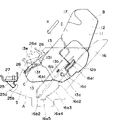
图8是图1所示处置盒从下部往上观察时的外透视图。Fig. 8 is an external perspective view of the process cartridge shown in Fig. 1 viewed from the lower part upward.
图9(a)是图1所示处置盒的清洁单元的外透视图,图(9b)是图1所示处置盒的显象单元的外透视图。Figure 9(a) is an external perspective view of the cleaning unit of the process cartridge shown in Figure 1, and Figure (9b) is an external perspective view of the developing unit of the process cartridge shown in Figure 1.
图10—17是侧视图,它们描绘出将图1所示处置盒安装到成象设备主机上或是将处置盒从主机上卸下的步骤。10-17 are side views depicting the steps of mounting the process cartridge shown in FIG. 1 to the main body of the image forming apparatus or removing the process cartridge from the main body.
图18是上述设备主机内部一部分的透视图。Fig. 18 is a perspective view of a part of the interior of the main body of the above device.
图19(a)是上述设备主机内部一不同部分的透视图,图19(b)是上述设备主机另一内部部分的侧视图。Fig. 19(a) is a perspective view of a different part inside the main body of the device, and Fig. 19(b) is a side view of another part inside the main body of the device.
图20和21是应用了本发明第一实施例的不同处置盒的侧视图。20 and 21 are side views of different process cartridges to which the first embodiment of the present invention is applied.
图22到25是应用了本发明第一实施例的几个不同处置盒的侧视图。22 to 25 are side views of several different process cartridges to which the first embodiment of the present invention is applied.
图26和27是处置盒一部分的剖面图,它们描绘出接点是如何与相应接点件保持接触的。Figures 26 and 27 are sectional views of a portion of the process cartridge illustrating how the contacts are held in contact with corresponding contact members.
图28是应用了本发明第一实施例的另一处置盒的侧视图。Fig. 28 is a side view of another process cartridge to which the first embodiment of the present invention is applied.
以下将描述本发明的最佳实施例。Preferred embodiments of the present invention will be described below.
图1是根据本发明的电子摄影成象设备实施例的剖面图,它示明了该设备的结构。图2是该设备的外部透视图。图3—8是应用了本发明第一实施例的处置盒的图,其中,图3为一横剖面图;图4为一示意性外透视图;图5为一右侧视图;图6为一左侧视图,图7为一由上部观察时的透视图;图8为一由下部往上观察时的透视图。〔电子摄影成象设备A和处置盒B〕Fig. 1 is a sectional view of an embodiment of an electrophotographic image forming apparatus according to the present invention, showing the structure of the apparatus. Fig. 2 is an external perspective view of the device. Fig. 3-8 is the figure that applied the disposal cartridge of the first embodiment of the present invention, wherein, Fig. 3 is a cross-sectional view; Fig. 4 is a schematic external perspective view; Fig. 5 is a right side view; Fig. 6 is A left side view, Fig. 7 is a perspective view viewed from the top; Fig. 8 is a perspective view viewed from the bottom up. [Electrophotographic imaging apparatus A and disposal cartridge B]
首先参看图1和2,来对采用了本发明第一实施例的电子摄影成象设备予以描述。图3是一处置盒B的侧视图。Referring first to Figs. 1 and 2, an electrophotographic image forming apparatus to which a first embodiment of the present invention is applied will be described. FIG. 3 is a side view of a process cartridge B. As shown in FIG.
参看图1,此电子摄影成象设备A是一类通过电子摄影成象方法在记录媒体上成象的成象设备。首先,在一作为载象件的鼓状电子摄影感传件(在下文称光敏鼓)上形成一色粉象。同时,与色粉象形成同步,放在一匣3a中的一种片状件记录媒体2则由一输送装置3从匣3a中输送出来,输送装置3包括一对拾取辊3b和3c,一对定位辊3d和3e,和类似部件。然后,将一电压加在作转印装置的转印辊4上,由此,包括在一处置盒B中的光敏鼓上所形成的色粉象就转印到记录媒体2上。接着,将已接收有色粉象的记录媒体传送到一定影装置5。此定影装置5包括一驱动辊5c和一定影辊5b,此定影辊包含有一加热器5a,并将热量与压力施加在通过定影装置5的记录媒体2上,从而将转印的色粉象定影。之后,载有已定影的色粉象的记录媒体2即由一组排送辊对3g,3h和3i通过一片状件反向通道3j输送并排送到一排送盘6中。此排送盘6设在设备A主机的顶部表面。此设备A还包括一可旋转的挡板3k和一排送辊对3m,当此挡板3k工作时,记录媒体2不用通过排送辊对3m倒转,也不用通过片状件反向通道3j就可以排送。Referring to Fig. 1, the electrophotographic image forming apparatus A is a type of image forming apparatus for forming an image on a recording medium by an electrophotographic image forming method. First, a toner image is formed on a drum-shaped electrophotographic sensor member (hereinafter referred to as a photosensitive drum) as an image bearing member. At the same time, synchronously with the toner image formation, a
在处置盒B中,作为载象件的光敏鼓的表面和一光敏层7e(图26),它们在光敏鼓旋转时,通过将一电压加在作为充电装置的一充电辊8上而均匀充电。接着,载有图象数据的一激光束即由一光学系统1通过一曝光孔9而投射到光敏鼓7上,并在光敏鼓7上形成一潜象。此潜象可由一显象装置9用色粉显象。In the process cartridge B, the surface of the photosensitive drum as the image bearing member and a
充电辊8设置成与光敏鼓7相接触的形式,以便为光敏鼓充电,且充电辊8在此位置上通过光敏鼓的旋转作用而旋转。显影装置9通过将色粉输送给光敏鼓7上要显影的部位而使在光敏鼓上所形成的潜象显影。光学系统1包括一激光二极管1a,一多角镜1b,一透镜1c和一全反射镜1d。The
在此显影装置9中,当装配有一磁铁的显影辊9c旋转时,由显影片9d摩擦充电的一色粉层就在显影辊9c表面形成。色粉从此色粉层供给光敏鼓上要显影的部位。当色粉与潜象相对应而转印到光敏鼓7上时,潜象就成为可见的了。此显影片9d控制涂覆在显影辊9c外围表面的色粉量。此外,用于循环色粉的一搅拌件9e可旋转地安装在显象辊9c邻近处。In this developing
接着,有一极性与色粉象相反的电压施加到转印辊4上,由此,光敏鼓7上的色粉象就转印在记录媒体2上。然后,光敏鼓7上剩余的色粉就由一清洁装置10除去。此清洁装置包括一弹性清洁片10a,而存留在光敏鼓7上的色粉便为此弹性清洁片10a刮下,收集在一废色粉收集器10b中。Next, a voltage having a polarity opposite to that of the toner image is applied to the
处置盒B由下列部分组成:盒架的色粉室部11(下文称色粉室框架),此部分构成存放色粉的色粉容器11a的一部分;盒架的显影室部12(下文称显影室框架),此部分包含显影辊9c一类的显影装置;及盒架的清洁装置部13(下文称清洁装置架),此部分包括光敏鼓7,清洁片10a等。此处置盒以可卸下的方式安装在设备A的主机上。The process cartridge B is composed of the following parts: the
处置盒B设有一曝光孔9,此曝光孔9使载有图象数据的光束能够照射在光敏鼓7上,处置盒B还设有一转印孔15,此转印孔15使光敏鼓7能够正对向记录媒体2。The process cartridge B is provided with an
下面来描述根据本发明处置盒B的实施例的机壳结构。本发明的处置盒是以下列方式装配。首先,连接色粉室框架11和显影室框架12。然后,将清洁装置框架13以可旋转的方式装附在由连接先前两框架部而构成的结构上,由此而形成了盒的机壳。接着,将上述光敏鼓7,充电辊8,显象装置9和清洁装置10等放置在此机壳内,而构成处置盒B。处置盒B则是以可卸下的方式安装在设于设备主机14之内的一盒安装装置上。〔处置盒B机壳的结构〕Next, the cabinet structure of the embodiment of the process cartridge B according to the present invention will be described. The process cartridge of the present invention is assembled in the following manner. First, the
本发明的处置盒B的机壳是通过连接色粉室框架11,显影室框架12和清洁装置框架13而构成,下面将对此结构予以描述。The casing of the process cartridge B of the present invention is constituted by connecting the
参看图3和9,色粉室框架11包括一色粉容器部分9a,此部分安装有一色粉输送件9b。显象辊9c和显象片9d安装在显象室框架12上,使色粉在显象室循环的搅拌件9e以可旋转方式安装在显象辊8c邻近处。把上述色粉室框架11和显象辊8c熔焊(在此实施例中用超声波焊接)到一起而构成一作为整体式的第二框架件的(参看图9(b))显象单元D。Referring to Figures 3 and 9, the
光敏鼓7,充电辊8和清洁装置11安装在清洁装置框架13上。另外,有一鼓屏蔽件18装附在框架的清洁装置部13上而构成了作为第一框架件(参看图9(a))的一清洁单元C,上述鼓屏蔽件当处置盒B在设备A主机之外时,将遮盖并保护光敏鼓7。The
然后,显象单元D和清洁单元C由一连接件22连接而构成处置盒B。更具体地可参看图9,其中有一轴20设在一臂部19的端部,此臂部19形成在框架的显象室部12的两个纵向端上(参看图9(b))。另一方面,有一凹部21设在框架的清洁装置部13(参看图9(a))每个纵向端上,在上述凹部21中安装着轴20以固定显象单元D和清洁单元C的位置关系。连接件22通过将轴20插入凹部21中而安装在框架的清洁装置部13上,由此,显象单元D与清洁单元C就以相互绕轴20而旋转的方式相连接,从而使显象辊9c可借显象单元D的自重而压向光敏鼓7。连接件22还设有压缩弹簧22a以使显象室框架12下压,而将显象辊9c可靠地压向光敏鼓7。另外,有一隔环9f设在显象辊9每个纵向端,其中,此隔环压在光敏鼓7上以在光敏鼓7和显象辊9c之间保持一段预定距离(约300μm)。Then, the developing unit D and the cleaning unit C are connected by a connecting
有关显象单元D与清洁单元C使用连接件22而形成的连接,已在申请号为18920/1992(1992年10月29日公开)的日本(公开)专利中公开。〔处置盒B的导引装置的结构〕The connection between the developing unit D and the cleaning unit C using the connecting
现在,参看图4—9,描述当把盒B安装到设备A主机上或是把盒B从主机上卸下时,引导盒B的导引装置,其中,图5是盒B相对于箭头X方向的右侧(从显象单元D一侧观察时的右侧)视图,而盒B即依此方向插在设备A的主机中,图6是其左侧视图。Now, with reference to Fig. 4-9, when box B is installed on the main body of equipment A or when box B is unloaded from main body, the guiding device of guiding box B is described, wherein, Fig. 5 is box B relative to arrow X The right side of the direction (the right side when viewed from the display unit D side) view, and the box B is inserted in the main machine of the device A in this direction, and Fig. 6 is its left side view.
从图中可明显看出,上述导引装置是分设在机壳表面的每个纵端100上,此导引装置在处置盒B插入设备主机14时或是从中卸下时作导向用。此导引装置包括作为第一导引件的一榫部13a,作为第二导引件的一长导杆12a和作为第三导引件的一短导杆13b。As can be clearly seen from the figure, the above-mentioned guiding device is separately located on each
上述榫部或突起13a为一用于以可旋转方式支承鼓轴7a的柱形件,上述鼓轴7a支承着光敏鼓7,并设在清洁装置框架13的每个侧面上。长导杆12a设在显象室框架12的每个纵向端面上,并跨接显象室框架12的表面和清洁装置框架13的表面。短导杆13b设在清洁装置框架13的每个纵向端面上,并位于榫部13a之上。The tenon or
长导杆12a在盒B的插入方向上(箭头X的示向)延伸,且它所取的插入角度设成与处置盒B插入的角度大致相等。榫部13a放置成使它落入在盒B插入方向上的长导杆12a的假想延伸的通道中的形式,且短导杆12b与长导杆13a大致平行。榫部13a,第二导引件12a和第三导引件13b也设在与图10中示明的纵向侧面相反的表面上,并且它们的结构与位置和图10中所示的相同。这三个导引件从处于同一平面的清洁装置框架13和显影室框架12两者之上,朝外突出大致相同的距离。The
下面将对此作更详细的描述。This will be described in more detail below.
作为第一导引件的榫部13设在清洁单元C的每个侧面C1(右侧面13C)和C2(右侧面13d)上,其中侧面C1是从显象单元D侧面观察盒B时(当从盒B插入方向的下游侧观察盒B时),清洁装置架13相对于光敏鼓7轴线方向的右侧部分13c。另一侧面C2是清洁装置框架13相对于光敏鼓7轴线方向的左侧部分。榫部13a为一柱形件,它在光敏鼓7的轴线方向从清洁装置框架13的两个纵向端面13c和13a突出。鼓轴7a由此柱形件13a支承,且此柱形件13a配合在鼓轴7a周围。换句话说,鼓轴7a是由一(将在下文描述的)导引件16a导引,且这根轴与该导引件二者中插有柱形件13a,然后,鼓轴7a的位置就由一凹槽16a5固定下来。A
第二导引件长导杆12a设在显象单元D的两个纵向端面D1(右侧部分12c)和D2(左侧面12d)上,其中,侧面部分的一表面D1是显象室架部12相对于光敏鼓7的轴线方向的右侧部分,另一表面D2是显象室架部12相对于光敏鼓7的轴线方向的左侧部分。长导杆12a离开柱形件13a放置,且位于柱形件13a相对于盒插入方向(箭头X方向)的上游侧。更确切地说,长导杆12a位于部位l之内,此部位在上部与下部假想线l1与l2(图5)之间形成,它平行于插入方向延伸并与柱形件13a的周面相切,并且长导杆12a通过它的插入端部12a1在清洁架部13的侧面区域延伸(以一约1mm至3mm的距离),从而跨接显象室架部12a与清洁装置架部13。The second guide
作为第三导引件的短导杆13b设在清洁单元C的侧面13c和13d上,并位于柱形件13a之上。更具体地说,当从盒插入方向观察时,短导杆13b大致位于柱形件13a正上方。换句话说,短导杆13b位于区域15之内,此区域形成在两条平行线13和14之间,上述两条线与柱形件13a的周面相切,并与盒插入方向(箭头X方向)大致垂直。另外,短导杆13b与长导杆13a大致平行。A
下面将列举导引件的常用尺寸。Common sizes of guides are listed below.
第一导引件13a直径约为10.0mm,(容许范围为7.5mm至10.0mm);第二导引件长约36.0mm(容许范围为15.0mm至41.0mm),宽约8.0mm(容许范围为1.5mm至10.0mm);短导杆13b长约10.0mm(容许范围为3.0mm至17.0mm),宽约4.0mm(容许范围为1.5mm至7.0mm)。另外,第一导引件13a的用面与第二导引件12a的插入端部12a1的距离约9.0mm。The diameter of the
第一导引件13a的周面与第三导引件13b的底端梢部13b1之间的距离约为7.5mm(容许范围为5.5mm至9.5mm)。The distance between the peripheral surface of the
下面,将描述设在清洁单元C顶面13d上的一控制接触部13e和一松释接触部13f。在此,顶面是指清洁单元C表面的这样一个部分,当处置盒B安装在设备A主机上时,这一部分将面向上。在此实施例中,上述部分是清洁单元C的顶面13i。Next, a
控制接触部13e与松释接触部13f设在上述表面13i的每个侧面端部13c和13d上。上述控制接触部13e固定了处置盒B在设备A主机中的位置。更具体地说,当处置盒B插入设备A主机中时,接触部13e就与设在设备A主机上的固定件25相接触(图10至17),从而限制了处置盒B的位置。当把处置盒B从设备A主机上卸下时,松释接触部13f即发挥作用。更确切地说,当把处置盒B从设备A主机中取出时,松释接触部13f就与固定件25相接触,而得以产生一可将盒B平稳地卸下的转矩。安装或卸下处置盒B的步骤将参考图10至17在以后描述。A
详细地说,有一凹部13g设在清洁单元C的顶面13i相对于盒插入方向的每一侧缘上。上述凹部设有:第一斜面13g1,它从盒B相对于插入方向(箭头X的示向)的前端朝后部向上延伸;第二斜面13g3,它从倾斜面13g3的顶端13g2朝后部向下延伸;和第四斜面13g5,它从斜面13g3的底端13g4朝后部再向下。在斜面13g5的底端13g6设有壁部13g7。第二斜面13g3与控制接触部13e对应,且臂部13g7与松释接触部13f对应。In detail, a
在此将列举上述部分常用的尺寸。The commonly used dimensions of the above parts will be listed here.
控制接触部13e相对于设备A主机中的盒B的水平方向l成O度角,长约6.0mm(容许范围为4.5mm至8.0mm)。松释接触部13f相对于水平方向1以θ1倾斜(约45度),长约10.0mm(容许范围为8.5mm至15.0mm)。The
接着参看图10—19,描述把处置盒B安装在设备A的主机上或是把它从主机上卸下的步骤。Next, referring to Figs. 10-19, the steps of mounting the process cartridge B on the main body of the apparatus A or removing it from the main body will be described.
假定具有上述结构的处置盒B能够安装到设在设备A主机之内的盒的容纳装置中,并能够从中卸下。It is assumed that the process cartridge B having the above-mentioned structure is mountable into and detachable from the cartridge accommodating means provided in the main body of the apparatus A.
参看图18和19,当操作者打开一旋转盖子15时,就露出盒的容纳空间5以及左和右盒安装导杆16,此二导杆安装在设备A主机的相应侧面上。每个盒安装导引杆16本身包括一对导引部,即一第一导引部16a和一第二导引部16b,上述两导引部在相对侧相互对应。通过将处置盒B沿导引部16a和16b插入设备A的主机并关上盖子15,就可把处置盒B安装到设备A的主机上。至于盒B的插入方向,它是与光敏鼓7的轴线相交的一方向;更具体地说,此方向如图10—17所示,大致与光敏鼓7的轴线垂直。在这种情况下,清洁单元C一侧为前侧,而显象单元D一侧为尾侧。18 and 19, when the operator opens a
在盒B上设有一凹部17,此凹部使操作者在安装或卸下盒B时能够更容易地将其握持住(见图3)。A
另外,处置盒B包括一鼓屏蔽件18(见图3),在安装或卸下盒B时此鼓屏蔽件的移动与盒B的移动相关联。当盒B从设备A的主机上卸下时,屏蔽件18关闭以保护光敏鼓7对着转印孔的部分。屏蔽件18由一臂部18a支承,且旋转盖子15绕一支点15a旋转(图1)。In addition, the process cartridge B includes a drum shield 18 (see FIG. 3) whose movement is associated with the movement of the cartridge B when the cartridge B is installed or removed. When the cartridge B is unloaded from the main body of the apparatus A, the
第一导引部16a是导引件16的底部,它导引设在处置盒B侧的长导杆12a和柱形件13a。此第一导引部16a包括一主导引部16a1,一阶梯部16a2,一凹部16a3,一辅助导引部16a4和一定位凹槽16a5,上述各部分以所陈述顺序相对于插入方向从上游侧至下游侧放置。主导引部16a1导引长导杆12a与柱形件13a。辅助导引部16a4将柱形件13a导引入定位凹槽16a5中。定位凹槽16a5处在柱形件13a安装的部位,而控制着盒B在设备A主机上的位置。第二导引部16b是导引件16的上部,它包括一倾斜面16b1和一凹部16b2,上述各部分按所陈述顺序相对于插入方向由上游侧至下游侧放置。The
另外,在设备A主机的盒的容纳空间S,有一固定件25(控制旋转件)设在左侧和右侧。它固定在保持件27上。此固定件25与前述控制接触部13e相接触,以控制盒B作顺时针走向旋转。更具体地说,当柱形件13a装入凹槽16a5中,且控制接触部13e与固定件25相接触时,盒B就会在设备A的主机上准确定位。此外,当将盒B取出时,固定件25就与松释接触部13f相接触,以助于将盒B平稳卸下。In addition, in the housing space S of the box of the main body of the device A, a fixing member 25 (controlling rotating member) is provided on the left and right sides. It is fixed on the
另外,在盒的容纳空间S中,有一加压件26设在左侧和右侧。此加压件26在顺时针走向上受一螺簧26a弹力的挤压,可绕一支点26b旋转,并弹性地挤压盒B的上表面,从而使当设备A受到振动时,盒B免于振动。In addition, in the housing space S of the cartridge, a pressing
现在参看附图,描述在安装或卸下盒B时,设在设备A主机上的安装导引件16与设在盒B上的导引件12a,13a和13b的关系。图10—15为示意图,它们描绘出从处置盒B开始安装到盒B最终定位到预定位置的各个步骤。在图10和15中,处置盒B的全侧视图以实线绘出,设备主机的安装导引件以双点划线(虚线)绘出。在图11—14中,绘出了盒B安装的中间步骤,其中只有盒B的导引件是用实线绘出,其它部分则用双点划线绘出。Referring now to the drawings, the relationship between the
首先,参看图10,在将盒B安装到设备A主机之间,盒B的柱形件13a和长导杆12a受导引部16a的导引而在导引部16a上滑动。此时,短导杆13b上以预定距离l(在本实施例中,约2.0mm至4.0mm)离开导引部16a,而不受其导引。First, referring to FIG. 10 , during installation of the cartridge B into the main body of the device A, the
于此同时,加压件26随设在盒B上表面的倾斜面13i向上旋转,使得它不妨碍盒的安装。当盒B进一步插入时,加压件26持续在盒B的上表面滑动,从而阻止盒B向上移动。即使在盒B已安装到设备A上之后,只要盒B在设备A中,加压件26就会持续挤压盒B的上表面。At the same time, the pressing
接着,当处置盒B进一步插入并处于图11中所绘出的状态时,柱形件13a即可随时通过设在第一安装导引部16a的阶梯部16a2而移动到也设在第一安装导引部16a的凹部16a3中。此导引部16a的凹部16a3在处置盒B插入一预定点(图15)时,即可让长导杆12a通过,而此凹部深度(在此实施例中,约4.0mm至8.0mm)设置成大于前述距离l(l<m)。应注意,短导杆13b不与第二导引部16b(16b1)相接触。Then, when the process cartridge B is further inserted and is in the state shown in FIG. 11, the
接着,当处置盒B又进一步插入而形成图12所描绘状态时,在盒B的柱形件13a到达凹部16a3底面之前,短导杆13b就与导引部16b相接触。换句话说,在此时,长、短导杆12a和12b都用作了插入导引件,因此,可能由阶梯部等传给盒B的振动就减弱了。Then, when the process cartridge B is further inserted to form the state depicted in FIG. 12, the
当处置盒B再进一步插入时,就形成图13所示明的状态。在此状态中,处置盒B长导杆12a的尾端在第一导引部16a凹部的边缘上,处置盒B的柱形件13a则与辅助导引部16a4相接触,并准备好可依随导引部16a4而运动。然后,处置盒B的柱形件13a和短导杆13b就分别由第一导引部16a和第二导引部16b导引(图14)。When the process cartridge B is further inserted, the state shown in Fig. 13 is formed. In this state, the tail end of the
之后,当处置盒进一步插入时,就形成图14所示明的状态,即短导杆13b来到第二导引部16b的凹部16b2。在较短的一段时间内,上述短导杆13b落进凹部16b2,只有柱形件13a在辅助导引部16a4与设备A的主机相接触,因此,处置盒B以逆时针走向稍作旋转,最后,柱形件13a落入导引部16a的凹槽16a5中(图15)。大致在此同时,设在清洁装置架部13上的控制接触部13c就与固定在设备A主机上的旋转控制部25a(图15)相接触。结果,处置盒B在设备A内的总的位置及取向就固定下来。在此状态下,处置盒B的位置由单独的一个点,即处置盒B的中心(柱形件13a)固定,其它导引件(长和短导杆12a和13b)则不与设备A主机的安装导引件16的任何部位相接触,因此,盒B的位置就准确固定下来。After that, when the process cartridge is further inserted, the state shown in FIG. 14 is formed, that is, the
控制接触部13e与旋转控制部25a的位置关系是这样的,即当驱动处置盒B时,处置盒B上所产生的转矩就由控制接触部13e与旋转控制部25a的触点所接收。控制接触部13e与柱形件13a中心的距离和旋转控制部25a与柱形件13a中心的距离长于长导杆12a与柱形件13a中心的距离和短导杆13b与柱形件13a的距离。用此,当驱动处置盒B时,处置盒B的定向将更为平稳地保持着。The positional relationship between the
在图15所示的状态中,设在光敏鼓7一轴端上的斜齿轮7b与设在设备A侧面的一驱动斜齿轮28相啮合。这样,驱动力就通过齿轮28和7b从设备A主机传输给光敏鼓,其中,当驱动力从齿轮28传输给齿轮7b时,盒B受到在顺时针走向上作用的力的影响。然而,盒B上所产生的转矩却受到接触部13e的控制。In the state shown in FIG. 15, the
加压件26将处置盒B从上压向下方。因此,即使柱形件13a没能落入设备A主机的凹槽16a5,在旋转控制部25a和接触部13e相接触点周围也会产生转矩,从而使得柱形件13a落入凹槽16a5中。The pressing
下面参看图16和17来描述把处置盒B从设备A取出的步骤。在图中,箭头Y所示方向即是将处置盒B卸下的方向。Next, the steps of taking out the process cartridge B from the apparatus A will be described with reference to FIGS. 16 and 17. FIG. In the figure, the direction indicated by the arrow Y is the direction in which the process cartridge B is removed.
参看图16,当把处置盒B从设备A卸下时,操作者握持住一柄部17(为安置此柄,在盒B上加工出一凹部)并用柄部17将盒B举起(箭头a的方向),这样,处置盒B就绕柱形件13a逆时针旋转。结果,处置盒B的控制接触部13f就与设在设备A主机上的固定件25的松释接触部25b相接触。当把处置盒B进一步举起时,处置盒B就绕控制接触部13f和松释接触部25b的接点D旋转。结果,柱形件13a便上升而脱离开凹槽16a5。此时,鼓齿轮7b便与驱动齿轮28之间脱离开啮合关系。在这种状态下,可按照图14,13,12,11和10所绘出的步骤及此次序将处置盒B从设备A中直接拉出。以后可以看到,上述这些凹部有助于抓持操作。Referring to Fig. 16, when the process cartridge B is unloaded from the apparatus A, the operator holds a handle 17 (for placing this handle, a recess is processed on the cartridge B) and lifts the cartridge B with the handle 17 ( The direction of the arrow a), so that the process cartridge B rotates counterclockwise around the
如上所述,根据本实施例,作为第二导引件的长导杆是在盒的插入方向上,能以跨接显象单元D与清洁单元C的侧面的方式而延伸,因此,处置盒在安装或卸下时,就不会摇晃。结果,处置盒的安装就更为可靠,这样就提高了操作效率。As described above, according to the present embodiment, the long guide bar as the second guide can be extended in a manner of bridging the sides of the developing unit D and the cleaning unit C in the insertion direction of the cartridge, so that the process cartridge There is no wobbling when installing or removing. As a result, the installation of the disposal cartridge is more reliable, thus improving the operational efficiency.
当处置盒插入设备主机或是从主机上卸下时,用作导引件的导引装置由三个导引件组成:柱形件13a,长导杆12a和短导杆13b,在安装或卸下处置盒时,它至少由两个导引件导引,因此,即使在设备主机的安装导引件上有阶梯部或类似部位,处置盒可能受到的震动也已缓冲。When the process cartridge is inserted into the main body of the apparatus or unloaded from the main body, the guide means used as the guide is made up of three guides: a
处置盒的位置由旋转控制部25a固定,此旋转控制部25a经定向成能控制在驱动处置盒时由盒上所产生的转矩,于是柱形件13a,从而是,其它的导引件(长和短导杆12a和13b)都不会与设备主机的导引件相接触;因此,当驱动成象设备时(在成象时),处置盒B将能更为平稳地保持其定位。The position of the process cartridge is fixed by the
对于安装或卸下处置盒的导引装置,在上述实施例中已举例说明了包括有三个在不同位置定位的导引件的一种导引装置。但是,本发明并不限于此例,而是可把上述导引装置取作为这样一种导引装置,它包括至少一个作为第一导引件的柱形件和一个作为第二导引件的长导杆,或是取作为这样一种导引装置,它除上面所叙述过的三个导引件外,还包括另外一个或若干个导引件。在安装或卸下处置盒时,这样的配置形式也能够使处置盒处于平稳状态,并提高操作效率。As for the guide device for installing or removing the process cartridge, a guide device including three guide members positioned at different positions has been exemplified in the above embodiments. However, the present invention is not limited to this example, but the above-mentioned guide device can be taken as a guide device comprising at least one cylindrical member as a first guide member and a cylindrical member as a second guide member. Long guide rod, or take as such a guiding device, it also comprises another one or several guiding parts besides the above-mentioned three guiding parts. When the process cartridge is installed or removed, such an arrangement can also keep the process cartridge in a stable state and improve operating efficiency.
再来参看图20和21,其中描述了除前述步骤之外的另一系列的其它安装或卸下处置盒B的步骤,在此,以相同参考数号标明了具有与前述实施例相同功能的构件,并且为了简洁而省略了对它们的描述。Referring again to Fig. 20 and 21, which have described another series of steps of installing or removing the process cartridge B except the aforementioned steps, at this point, the components having the same functions as those of the aforementioned embodiments are marked with the same reference numerals , and their descriptions are omitted for brevity.
在本实施例中,处置盒B包括用作定位部的一对轴40,它们从处置盒架的相应侧面突出,且与光敏鼓7a的旋转轴7a在同一直线上(图20仅示明一例);还有一些导引件16,这些导引件位于相应的左侧和右侧。导引件16上设有导引凹槽16i,此导引凹槽16i倾斜向下延伸,并在安装盒B时导引定位轴40。在导引凹槽16i的最深端有一凹部16k。当定位轴40落入此凹部16k中时,盒B在设备中的位置就固定下来。In this embodiment, the process cartridge B includes a pair of
换句话说,处置盒B在设备A中的位置随着它插入到设备A中即被固定下来,而允许它的从处置盒架相应侧面突出的定位轴能够依随相应的定位凹部16i,直到轴40落入到相应的定位凹部16k中。In other words, the position of the process cartridge B in the apparatus A is fixed as it is inserted into the apparatus A, allowing its positioning shafts protruding from the corresponding sides of the cartridge holder to follow the
参看图2和21,在此实施例中,控制接触部13e和松释接触部13f也都设置在盒架上部,但是旋转控制部25a则与松释接触部25b接合为一单一部件。Referring to Figures 2 and 21, in this embodiment, the
换句话说,在处置盒B的上表面设有一凹部,且此凹部13g的两个表面分别充当了控制接触部13e和松释接触部13f。成象设备A也设有固定件25,此固定件25放置成使它位于已安装的处置盒B之上并装入凹部13g中的形式。此固定件25的两个表面分别用作旋转控制部25a和松释接触部25b。In other words, a recess is provided on the upper surface of the process cartridge B, and both surfaces of this
当已按上述形式布置就位,则当处置盒B装入设备A主机中时,如图20中所示,控制接触部13e就与旋转控制接触部15a相接触。当将处置盒B取出时,在操作者握持住并举起盒B时,松释接触部13f即与松释接触部25b相接触,这样,盒B就绕触点D旋转。结果,柱形件15a就从凹槽16a5升出,而鼓齿轮7b就与驱动齿轮28脱开啮合关系。When arranged in place as described above, when the process cartridge B is loaded into the apparatus A main body, as shown in FIG. 20, the
由于固定件25不在记录媒体的通道上,所以不必担心固定件25妨碍记录媒体;因此,不会限制此固定件的定位。Since the fixing
另外,由于有一整体的单一件包括着旋转控制接触部25a和松释接触部25b;因此,就可以生产出更为精确的部件;部件的成本得以降低;同时其定位精度也能够提高。In addition, since there is an integral single piece including the rotation
此实施例还典型地说明了一种情况,其中固定件25放置成使它位于已安装的处置盒B上方的形式。不过,此固定件25也可放置成使它位于已安装的处置盒B侧面的形式。This embodiment also typically illustrates a case where the fixing
下面,参看图22和23来描述安装或卸下处置盒B的另一系列步骤。Next, another series of steps for installing or removing the process cartridge B will be described with reference to FIGS. 22 and 23. FIG.
参看图22,在此实施例中,控制接触部42在处置盒B框架的上表面相对于处置盒B插入成象设备A的前端部上形成。此控制接触部42与旋转控制部41相接触,后者将在以后描述。在处置盒B框架的底面上,还形成有一松释接触部44。此松释接触部44与松释突起43相接触,上述突起43将在下文描述。Referring to FIG. 22, in this embodiment, a
再来参看图22,其中,设备A包括:旋转控制部41,它定位成当处置盒B沿导引凹槽16i插入,且定位轴40落入凹部16k中时,处置盒B处于旋转控制部41的上方;以及松释突起43,此突起43设置成位于松释接触部44的下方。Referring again to Fig. 22, wherein, apparatus A comprises: rotation control
处置盒B包括安装在光敏鼓7的旋转轴7a上的鼓齿轮7b。此鼓齿轮在盒B的定位轴40落入凹部16k之前,与设在设备A主机上的驱动齿轮28相啮合。驱动力通过这种啮合而传送给光敏鼓7。此时,当齿轮7b与28相啮合时,就有一绕定位轴40的顺时针转矩在处置盒B上产生,此转矩是由操作者为将齿轮7b和28相啮合而施加的力F所产生的。此转矩使处置盒B的控制接触部42与旋转控制部41相接触,从而使处置盒B的定向得到保持。The process cartridge B includes a
另一方面,参看图23,当将处置盒卸下时,操作者可首先紧握住盒B的柄部并将其向上拉,这样就使处置盒B绕定位轴40逆时针方向旋转。结果,松释接触部44就与松释突起43相接触。接着,当操作者将处置盒继续向上拉时,处置盒B此时便绕接触部44与43的触点D旋转。换句话说,处置盒B起着类似于一杠杆的作用,其支点就是接点D;因此,定位轴40从定位凹部16k中举起,同时,鼓齿轮7b与驱动齿轮28的啮合脱开。在此状态下,处置盒B可沿导引凹槽16i从设备A主机上直接拉出。On the other hand, referring to FIG. 23, when the process cartridge is unloaded, the operator can first hold the handle of the cartridge B and pull it upwards, so that the process cartridge B is rotated counterclockwise around the positioning
当处置盒B的接触部42和44以及成象设备A主机的旋转控制部41和松释接触部43取以上所述结构时,处置盒B就可以妥当地安装,其定向能妥当地保持;还有,在卸盒时,可以很容易地松释齿轮。When the
下面参看图24和25,对安装或卸下处置盒B的另一系列步骤予以描述。Next, referring to Figs. 24 and 25, another series of steps for mounting or detaching the process cartridge B will be described.
图24和25所描绘的实施例与图22和23所描绘的实施例不同之处在于,处置盒B的松释接触部44位于盒框架侧面上,与接触部44相接触的成象设备A侧的松释接触部43则位于设备主机的内侧面上。The embodiment depicted in Figures 24 and 25 differs from the embodiment depicted in Figures 22 and 23 in that the
换句话说,有一凹部45在盒框架的每个侧面形成,凹部中的一面(凹部45的顶面)用作了松释接触部44。至于松释接触部43,它们在空间S相应侧壁上,从相应的预定位置突入盒的容纳空间S。In other words, a
当作出如上所述的布置形式时,不仅能获得与先前实施例相同的效果,而且能够减少对部件定位次数的要求。更具体地说,参看图25,接触部44与接触突起43相接触,且它们之间的触点充当了盒B旋转的中心。接触部44和接触突起43不在记录媒体的通道中;因此,不必担心它们会影响记录媒体,这样,又减少了对部件定位的限制。〔电接点的结构〕When the arrangement form as described above is made, not only the same effect as the previous embodiment can be obtained, but also the requirement for the number of parts positioning can be reduced. More specifically, referring to FIG. 25, the
以下参看图5,8,9和19,描述电接点的结构,当处置盒B安装到设备A主机上时,上述电接点构成了处置盒B与设备A主机的电连接。5, 8, 9 and 19, describe the structure of the electrical contacts, when the process box B is installed on the device A main body, the electrical contacts constitute the electrical connection between the process box B and the device A main body.
处置盒B设有一批电接点:(1)导电接地接点119,此接点电连接到光敏鼓7上的通过设备主机A使鼓7接地;(2)充电偏压接点120,此接点电连接到充电辊轴8a上;(3)导电显象偏压接点121,此接点电连接到显象辊9b上,以从设备主机A上施加一显象偏压;(4)导电色粉探测接点122,以接点电连接到一天线(线)上,以探测余留的色粉量。所有这四个接点119—122都暴露在处置盒框架的侧面(右侧),其间隔大至能避免在接点间发生漏电现象。在此应注意到色粉探测接点122作为处置盒探测接点有两个,以用于探测设备A主机中的处置盒是否存在。Disposal box B is provided with a batch of electrical contacts: (1)
接地接点119是由光敏鼓7的导电轴向轴7a或一在轴7上模制出的为树脂材料制的插入件构成。在本实施例中,它由铁之类的金属轴7a构成。其它的接点120,121和122是0.1mm至0.3mm厚的导电金属片,它们植入上述表面以使其脚部伸入处置盒内部。充电接点120暴露在清洁单元C的驱动侧面(侧面C1)上,显象接点121和色粉探测接点122暴露在显象单元D的驱动侧面(侧面D1)上。The
更具体地说,在此实施例中,如前所述,斜齿轮7b设在光敏鼓7轴向的一端。此斜齿轮7b与设在设备A主机上的斜齿轮28相啮合以使光敏鼓7旋转。当此斜齿轮7b旋转时,它产生一推力,此推力则压迫光敏鼓7,此光敏鼓7安装在清洁装置架部13上,并在其纵向上向斜齿轮7b的方向留有稍许空隙。结果,斜齿轮28的一侧面7b1与处置盒框架的清洁装置架部13的一侧面13b的内面13b1保持接触,这样就限定了处置盒B内的光敏鼓7的位置。接地接点119和充电偏压接点120暴露在上述框架的清洁装置部13的一侧面13b上,其中,接地接点119在鼓轴7a的一端,并略微向外突出(约0.8mm)到上述柱形件13a的端部之外。上述鼓轴7a通过涂覆有一光敏层7e的鼓柱7d(在此实施例中为铝柱)而放置,并由柱形件13a在鼓轴每一端支承着,此柱形件13a又在侧壁13c和13d上受到支承。上述鼓柱7d和轴7a由一接地板7f连接,此接地板7f又与鼓柱7d的内面7d1和轴7a的周面7a1相接触。More specifically, in this embodiment, the
充电偏压接点120几乎正位于长导杆12的上方,即它与框架的清洁装置部13相邻,此清洁装置部13支承着充电辊8(图5)。另外,充电偏压接点120通过一导电件120a电连接到充电辊轴8a上,上述导电件120a与充电辊轴8a相接触。The charging
下一步将描述显象偏压接点121和色粉探测接点122。这两个接点121和122位于显象单元D的一个侧面D1上,即上述框架的清洁装置部13的侧面13b的同一侧面上。显象偏压接点121在长导杆12a的正下方,并与上述框架部12c相邻,在此处,显象辊9c中包含的磁铁9d受到支承(图5),并通过导电件121a电连接到显象辊9c上,上述导电件121a与显象辊9c的侧端相接触。(图9(b)。色粉探测接点122设置在长导杆12a相对于处置盒插入方向(箭头A的方向)的上游侧,并通过导电件9f连接到天线杆9e上,上述天线杆9e平行于显象辊9c并在显象辊9c的纵向上延伸,上述导电件9f与天线杆9e相接触。天线杆9e设置成至显象辊9c有一预定的距离。此天线杆9e与显象辊9c之间的电容对应于两部件间余留的色粉量而变化;因此,可以通过设备A主机中的一探测电路测量当作电位差变化的电容的变化而探测出余留的色粉量。Next, the developing
在此,名词“余留色粉量”意思是一定量的色粉,这时色粉因存在于显象辊9c和天线杆9e之间而产生一预定量的电容。换句话说,探测出预定量的电容时,便意味着色粉室11a中余留的色粉量已达到预定的量。Here, the term "amount of remaining toner" means a certain amount of toner at which a predetermined amount of capacitance is generated by the presence of the toner between the developing
这样,可用探测电路探测出电容已达到一预定的第一数值,上述探测电路设在设备A的主机内并通过色粉探测接点122连接到处置盒B;由此就能确定色粉室11a中余留的色粉量已达到预定的量。当探测出电容已达到上述的第一确定数值时,设备A主机会发出需要更换处置盒B的信号(例如,闪光,蜂鸣声)。当由探测电路探测出的结果与一预定的第二数值相等时,探测电路就会确定处置盒B已安装到了设备A主机上,上述的第二数值小于第一数值。只有当探测电路探测出处置盒B已安装在设备主机上时,探测电路才允许驱动设备A主机。也可以安排设置一种警告信号(例如,连续的闪烁之类的信号),以通知操作者处置盒B不在设备中。In this way, the detection circuit can be used to detect that the capacitance has reached a predetermined first value. The above-mentioned detection circuit is arranged in the main body of the device A and connected to the process cartridge B through the
接着来描述设在上述盒B上的接点与设在设备主机上的接点之间的连接。Next, the connection between the contacts provided on the above box B and the contacts provided on the main body of the device will be described.
参看图19,有四个接点件设置在成象设备A的盒的容纳空间S的一侧壁上(与接地接点119相接触的接地接点件123,与充电偏压接点120相接触的充电偏压接点件124,与显象偏压接点121相接触的显象接点件125和与色粉探测接点122相接触的色粉探测接点件126),当处置盒安装到设备A上时,上述接点件与相应的接点119—122相接触。Referring to Fig. 19, there are four contact pieces arranged on the side wall of the accommodating space S of the box of the image forming apparatus A (the
如图19(a)和19(b)所示,接地接点件123与凹槽16a5相对应而设置。显象偏压接点件125和色粉探测接点件126设置在第一导引部16a之下。充电偏压接点件设在第二导引部16b之上。As shown in FIGS. 19(a) and 19(b), the
在此将描述接点与导引件之间的位置关系。Here, the positional relationship between the contact and the guide will be described.
首先是垂直方向上的位置关系(从水平方向观察时),显象偏压接点121是在最底端的一个;色粉探测接点122,长导杆12a与柱形件13a(接地接点119)设置在偏压接点121之上,并约在相同水平线上;它们的上方是短导杆13b,最高的一个是充电偏压接点120。至于处置盒插入方向上的位置关系(箭头X的方向),色粉探测接点122是最上游的一个;下一个是长导杆12a;在再下游的位置上的是充电偏压接点120和显象偏压接点121;在最下游位置上的是短导杆13b和柱形件13a(接地接点119)。如上所述地布置接点,就可使充电偏压接点120靠近充电辊8;显象偏压接点121靠近显象辊9c;色粉探测接点122靠近天线杆9e;接地接点119靠近光敏鼓7。因此,可以缩短接点的布线。First is the positional relationship in the vertical direction (when viewed from the horizontal direction), the
接点的尺寸如下:充电偏压接点120高和宽都约为10.0mm容许范围为8.0mm至12.0mm);显象偏压接点121高约9.0mm(容许范围为6.0mm至12.0mm),宽约8.0mm(容许范围为5.0mm至11.0mm),色粉探测接点122高约8.0mm(容许范围为6.0mm至10.0mm),宽约9.0mm(容许范围为7.0mm至11.0mm);接地接点119为圆形,其直径约7.0mm。充电偏压接点120,显象偏压接点121和色粉探测接点122均呈矩形。The dimensions of the contacts are as follows: the charging
接地接点件123为一导电板簧件,它安装在凹槽16a5中,凹槽16a5中设有柱形件13a(其上装有光敏鼓7的鼓轴7a)以固定上述盒B的位置,凹槽16a5上还安装有接地接点119,由此,接地接点件123就通过设备A主机的底盘而接地(图16和26)。其它的接点件124,125和126安装在相应的接点件盒盖127上,并安装成可在相应的压缩弹簧129作用下而从接点件盒盖127中弹出。下面对照充电偏压接点件124来描述上述布置形式。参看图26,充电偏压接点件124放在一接点件盒盖之下,使它能够弹出但不会脱开,然后,将此接点件盒盖127固定到一电路板128上,此电路板128安装在设备主机的一面侧壁上,这样,接点件就由导电压缩弹簧129电连接到相应的布线阵列上。The
然后,参看图27来描述当参照充电偏压接点件119将处置盒B装入成象设备A时,处置盒侧的接点是如何与成象设备上相应的接点件相接触的。图27是一说明性附图,它描绘出成象设备A中处置盒B的状态,其中,箭头H表示出设备主机上的充电偏压接点在处置盒B插入成象设备A时,相对于处置盒B的运动。在此应注意,图27是沿图5中线O所截取的横部面图。Then, referring to FIG. 27, when the process cartridge B is loaded into the image forming apparatus A with reference to the charging
在将处置盒B装入成象设备A时,使用了导引件16a和16b作为导引件,充电偏压接点件124在到达它将固定放置的预定位置之前,处于图27中所描绘的状态。此时,充电偏压接点件124不与框架的清洁装置部13的平面20相接触。当上述盒B进一步插入时,充电偏压接点件124前进到图27中一位置(b)。在此状态下,它与在框架的清洁装置部13的侧壁上所形成的斜面31(图5)保持接触并在此斜面上滑动,因此,它逐渐受到压迫,从而逐渐压紧压缩弹簧129;并平稳地移动到平面32上,而上述充电偏压接点120就暴露在此平面32上。当插入的盒B到达预定位置时,接点件124即到达图27中的一位置(c),并在该处与充电偏压接点120相接触。其它的接点件125和126都分别以同样的方式与接点121和122相接触。When the process cartridge B is loaded into the image forming apparatus A, using the
当按以上所述布置就位后,在上述盒B由导引件16导引入预定的匣的容纳位置时,这些接点与相应的接点件就会可靠地就位成彼此相接触。When arranged in place as described above, these contacts and corresponding contact members are securely positioned in contact with each other when the above-mentioned cartridge B is guided by the
另外,当处置盒B定位到设备A主机中的预定位置时,板簧状的接地接点件123就会与从柱形件13a突出的接地接点119相接触(图26)。In addition, when the process cartridge B is positioned at a predetermined position in the main body of the apparatus A, the leaf spring-shaped
再来描述通过驱动成象设备A而使光敏鼓7旋转的情况。在轴向上,给光敏鼓7一个约2mm至3mm的推压空隙,可使处置盒B能更容易地装入成象设备A中。为此,必须使充电偏压接点件124等能够弹出一段比上述推压空隙长的距离。此外,在此实施例中,设有一板簧45,当上述盒B在设备主机中时,上述板簧45即把处置盒B压向设备主机的一个侧面(接点件123—126所在的侧面)。此板簧45则设在上述接点件所在一侧的相对侧面上,并且是在第一安装导引件16a的上方。Next, the case where the
另外,当处置盒B的接点119—122与在此实施例中一样,设置在斜齿轮7b所在的一侧面上(驱动侧的侧壁)时,就可以在上述盒B的相同侧面上,形成通过斜齿轮7b来由设备主机用机械方式驱动处置盒B的连接,以及通过接点119—122来在处置盒B与设备主机之间实现电连接。因此,当把处置盒B上述的侧面用作参考侧面时,部件尺寸上的总的误差就会减少,这样就可以更准确地安装接点和斜齿轮。此外,当使用一种斜齿轮,且此齿轮的齿在某一方向上加工成使齿轮产生一个朝向斜齿轮所在一侧的推力时,光敏鼓7在轴向上的位置就固定在接点所在的一侧;因此,在此情形下,除了以前提到的效果外光敏鼓7与接点位置关系的精度也提高了,还有,当把用于开/并鼓屏蔽件18的一个操作杆18b按照它在前述实施例中相同的情形,设置到与接点119—122所在侧面相反的侧面上时,在上述盒B插入成象设备A时,由接点119—122在处置盒一侧面所产生的摩擦阻力,当鼓屏蔽件18处于打开时,就会分布到该另一侧面上;换句话说,在上述盒B插入时产生的阻力就会在处置盒B的纵向上均匀地分布开。因此,处置盒B能够平稳地插入。In addition, when the contact points 119-122 of the process cartridge B are provided on the side where the
此外,如同前面的实施例所描述的,当处置盒B的所有接点都位于处置盒框架的同一侧壁上,且处置盒B放在处于板簧所产生的弹性压力之下时,就能在这些接点与设备主机例上相应的接点件之间提供稳定的电连接。In addition, as described in the previous embodiment, when all the joints of the process cartridge B are located on the same side wall of the process cartridge frame, and the process cartridge B is placed under the elastic pressure produced by the leaf spring, the A stable electrical connection is provided between these contacts and the corresponding contacts on the main body of the device.
图28示明了一种布置形式,其中,接点位于上述操纵杆18b所在的一侧。这种布置形式也能够充分地提供前述效果。Figure 28 shows an arrangement in which the contact point is located on the side where the above-mentioned
另外,在前面的实施例中,处置盒B属于用来形成单色图象的类型,但是,本发明却是可用于多色处置盒的,这种多色处置盒包括两个或更多的显象装置,可用于形成多色图象(双色,三色或全色图象)。In addition, in the foregoing embodiments, the process cartridge B is of the type for forming monochromatic images, but the present invention is applicable to multicolor process cartridges comprising two or more A developing device that can be used to form multicolor images (two-color, three-color or full-color images).
至于电子摄影光敏件,也并不限于上述的光敏鼓。本发明也可用于下列情形。首先,可把光电导材料用作有关的光敏材料。至于这类光电导材料,可以采用无定形硅,无定形硒,氧化锌,氧化钛,以及有机光电导体等类似的材料。另外,关于放置光敏材料所用基底件的形状,可使用鼓状或带状的基底件。例如,如果基底件是鼓状的,可用类似的相应装置,将这类光导电材料涂覆沉积或铺放到铝合金或类似材料制的柱形件上。As for the electrophotographic photosensitive member, it is not limited to the above-mentioned photosensitive drum. The present invention is also applicable to the following cases. First, a photoconductive material can be used as a related photosensitive material. As such photoconductive materials, amorphous silicon, amorphous selenium, zinc oxide, titanium oxide, and organic photoconductors and the like can be used. In addition, regarding the shape of the base member on which the photosensitive material is placed, a drum-shaped or belt-shaped base member may be used. For example, if the base member is in the form of a drum, a similar corresponding device can be used to deposit or lay down such a photoconductive material on a cylindrical member made of aluminum alloy or similar material.
关于显象方法,本发明是可以与各种周知的方法相匹配的,如双组份磁刷显象法,淋液显象法,触地(touch down)显象法,或混浊式显象法等类似方法。Regarding the developing method, the present invention can be matched with various known methods, such as two-component magnetic brush developing method, shower developing method, touch down developing method, or turbid developing method method and the like.
另外,关于充电装置的结构,在第一实施例中使用了所谓的接触充电法,但是,本发明显然也可应用于其它传统的充电法,例如这其中的一种方法是将铝之类的金属盖片放在钨丝的三个侧面,这样,通过对钨丝施加一高压而产生的阳离子或阴离子就会传送到光敏鼓上表面而使它均匀充电。In addition, regarding the structure of the charging device, the so-called contact charging method is used in the first embodiment, but the present invention is obviously also applicable to other conventional charging methods, for example, one of the methods is to use aluminum or the like Metal covers are placed on three sides of the tungsten wire, so that positive ions or negative ions generated by applying a high voltage to the tungsten wire will be transferred to the upper surface of the photosensitive drum to charge it evenly.
此外,上述充电装置除前面已描述过的辊状外也可以取板状(充电板),盘状,杆状,丝状或类似的形状。In addition, the above-mentioned charging means may also take the shape of a plate (charging plate), a disc, a rod, a wire or the like in addition to the roll shape described above.
关于清洁光敏鼓上余留色粉的方法,清洁装置可由板片,毛刷,磁性刷等构成。Regarding the method for cleaning the remaining toner on the photosensitive drum, the cleaning device can be composed of a plate, a hair brush, a magnetic brush, and the like.
如以上所述,根据本发明,已提出了一种处置盒以及可采用这种处置盒的一种成象设备,其中,处置盒与成象设备主机的电连接更为可靠与精确。As described above, according to the present invention, there have been proposed a process cartridge and an image forming apparatus employing the process cartridge, wherein the electrical connection between the process cartridge and the main body of the image forming apparatus is more reliable and precise.
尽管上面业已对照在此公开的结构就本发明作了描述,但本发明并不限于这里所列述的种种细节,而应把本发明的应用范围视作为将概括包含在本发明后附权利要求书的为改进目的或是其相关领域内所涉及的那种改型与变更形式。Although the invention has been described above with reference to the structure disclosed herein, the invention is not limited to the details set forth herein, but the scope of application of the invention is considered to be broadly encompassed by the appended claims of the invention. Modifications and alterations of the book for the purpose of improvement or those involved in its related field.
Claims (67)
Applications Claiming Priority (6)
| Application Number | Priority Date | Filing Date | Title |
|---|---|---|---|
| JP8978894 | 1994-04-27 | ||
| JP089788/1994 | 1994-04-27 | ||
| JP089788/94 | 1994-04-27 | ||
| JP093643/1995 | 1995-04-19 | ||
| JP093643/95 | 1995-04-19 | ||
| JP09364395A JP3869868B2 (en) | 1994-04-27 | 1995-04-19 | Process cartridge and image forming apparatus |
Publications (2)
| Publication Number | Publication Date |
|---|---|
| CN1125332A true CN1125332A (en) | 1996-06-26 |
| CN1064145C CN1064145C (en) | 2001-04-04 |
Family
ID=26431199
Family Applications (1)
| Application Number | Title | Priority Date | Filing Date |
|---|---|---|---|
| CN95104234A Expired - Fee Related CN1064145C (en) | 1994-04-27 | 1995-04-26 | Process cartridge and image forming apparatus |
Country Status (8)
| Country | Link |
|---|---|
| US (2) | US5873012A (en) |
| EP (1) | EP0679964B1 (en) |
| JP (1) | JP3869868B2 (en) |
| KR (1) | KR0166647B1 (en) |
| CN (1) | CN1064145C (en) |
| AU (1) | AU681494B2 (en) |
| DE (1) | DE69518570T2 (en) |
| HK (1) | HK1012044A1 (en) |
Cited By (4)
| Publication number | Priority date | Publication date | Assignee | Title |
|---|---|---|---|---|
| CN1294463C (en) * | 2002-01-11 | 2007-01-10 | 佳能株式会社 | Processing case and electronic photograph imaging appts. |
| CN106547187A (en) * | 2015-09-16 | 2017-03-29 | 佳能株式会社 | Box and supporting member |
| CN106547184A (en) * | 2015-09-16 | 2017-03-29 | 佳能株式会社 | Box and the part for box |
| CN110632837A (en) * | 2018-06-25 | 2019-12-31 | 夏普株式会社 | Process cartridge and image forming apparatus including process cartridge |
Families Citing this family (73)
| Publication number | Priority date | Publication date | Assignee | Title |
|---|---|---|---|---|
| JP3869868B2 (en) * | 1994-04-27 | 2007-01-17 | キヤノン株式会社 | Process cartridge and image forming apparatus |
| JP3530644B2 (en) | 1995-07-31 | 2004-05-24 | キヤノン株式会社 | Developing frame, process cartridge, and electrophotographic image forming apparatus |
| JP3359194B2 (en) | 1995-07-31 | 2002-12-24 | キヤノン株式会社 | Developing holder, process cartridge, and electrophotographic image forming apparatus |
| JP3382465B2 (en) * | 1996-07-04 | 2003-03-04 | キヤノン株式会社 | Process cartridge and electrophotographic image forming apparatus |
| JP3372772B2 (en) * | 1996-07-22 | 2003-02-04 | キヤノン株式会社 | Process cartridge and electrophotographic image forming apparatus |
| JP3416486B2 (en) * | 1996-09-30 | 2003-06-16 | キヤノン株式会社 | Developing cartridge and electrophotographic image forming apparatus |
| JPH10228223A (en) * | 1997-02-14 | 1998-08-25 | Canon Inc | Process cartridge and electrophotographic image forming device |
| JP3332813B2 (en) * | 1997-08-01 | 2002-10-07 | キヤノン株式会社 | Process cartridge and electrophotographic image forming apparatus |
| AU750160B2 (en) * | 1997-09-01 | 2002-07-11 | Canon Kabushiki Kaisha | Process cartridge and electrophotographic image forming apparatus |
| JPH1192040A (en) * | 1997-09-22 | 1999-04-06 | Toshiba Corp | Image forming device |
| US6041196A (en) * | 1997-10-27 | 2000-03-21 | Canon Kabushiki Kaisha | Developer detecting apparatus for detecting the position of an upper surface of developer contained in a container and process cartridge comprising such apparatus |
| JP3290619B2 (en) * | 1997-11-20 | 2002-06-10 | キヤノン株式会社 | Process cartridge and electrophotographic image forming apparatus |
| JPH11161131A (en) * | 1997-11-29 | 1999-06-18 | Canon Inc | Processing cartridge and electrophotographic image forming device |
| JPH11249494A (en) | 1998-03-03 | 1999-09-17 | Canon Inc | Drum flange, cylindrical member, process cartridge and electrophotographic image forming device |
| JPH11249495A (en) * | 1998-03-03 | 1999-09-17 | Canon Inc | Grounding member, cylindrical member, process cartridge and electrophotographic image forming device |
| JP3530752B2 (en) * | 1998-10-09 | 2004-05-24 | キヤノン株式会社 | Electrophotographic image forming apparatus, process cartridge, developing device, developer supply container, and measuring component |
| JP3673658B2 (en) | 1998-10-28 | 2005-07-20 | キヤノン株式会社 | Process cartridge and electrophotographic image forming apparatus |
| JP3697090B2 (en) | 1998-10-26 | 2005-09-21 | キヤノン株式会社 | Electrophotographic image forming apparatus |
| JP3684092B2 (en) | 1998-10-26 | 2005-08-17 | キヤノン株式会社 | Electrophotographic image forming apparatus |
| JP2000206774A (en) | 1998-11-13 | 2000-07-28 | Canon Inc | Remaining-toner quantitative detector, remaining-toner quantitative detecting method, profess cartridge, and electrophotographic image forming device |
| JP3748506B2 (en) | 1999-05-20 | 2006-02-22 | キヤノン株式会社 | Process cartridge and process cartridge assembly method |
| JP3320399B2 (en) | 1999-05-20 | 2002-09-03 | キヤノン株式会社 | Process cartridge, method of assembling process cartridge, and electrophotographic image forming apparatus |
| JP3320398B2 (en) | 1999-05-20 | 2002-09-03 | キヤノン株式会社 | Process cartridge and electrophotographic image forming apparatus |
| JP2001066871A (en) * | 1999-08-30 | 2001-03-16 | Canon Inc | Developing device, process cartridge and electrophotographic image forming device |
| US6549736B2 (en) | 2000-01-19 | 2003-04-15 | Canon Kabushiki Kaisha | Process cartridge, engaging member therefor and method for mounting developing roller and magnet |
| CN1237416C (en) | 2000-06-09 | 2006-01-18 | 佳能株式会社 | Connection method between developing device, process cartridge, developing frame, and developer frame, and flexible seal |
| JP3658289B2 (en) * | 2000-07-28 | 2005-06-08 | キヤノン株式会社 | Process cartridge and electrophotographic image forming system |
| JP3432208B2 (en) * | 2000-11-17 | 2003-08-04 | キヤノン株式会社 | Process cartridge, electrophotographic image forming apparatus, and cartridge mounting method |
| JP3658315B2 (en) | 2000-12-19 | 2005-06-08 | キヤノン株式会社 | Process cartridge and electrophotographic image forming apparatus |
| JP4677093B2 (en) | 2000-12-25 | 2011-04-27 | キヤノン株式会社 | Process cartridge |
| US6636791B2 (en) * | 2001-01-05 | 2003-10-21 | Calsonic Kansei Corporation | Collision record apparatus, collision state estimation method, and record medium |
| JP3697168B2 (en) | 2001-03-09 | 2005-09-21 | キヤノン株式会社 | Process cartridge and electrophotographic image forming apparatus |
| JP3564080B2 (en) | 2001-04-27 | 2004-09-08 | キヤノン株式会社 | Process cartridge remanufacturing method |
| JP3542569B2 (en) | 2001-04-27 | 2004-07-14 | キヤノン株式会社 | Process cartridge remanufacturing method |
| JP3840063B2 (en) | 2001-04-27 | 2006-11-01 | キヤノン株式会社 | Process cartridge |
| JP2003208074A (en) * | 2002-01-11 | 2003-07-25 | Canon Inc | Process cartridge and electrophotographic image forming device |
| JP3595798B2 (en) * | 2002-01-31 | 2004-12-02 | キヤノン株式会社 | Process cartridge and electrophotographic image forming apparatus |
| JP3809402B2 (en) * | 2002-05-17 | 2006-08-16 | キヤノン株式会社 | Process cartridge and electrophotographic image forming apparatus |
| JP3684209B2 (en) * | 2002-05-31 | 2005-08-17 | キヤノン株式会社 | Cartridge and electrophotographic image forming apparatus |
| JP3797295B2 (en) * | 2002-08-09 | 2006-07-12 | ブラザー工業株式会社 | Detachable member, developing device, process device, and image forming apparatus |
| US6801733B2 (en) * | 2003-01-21 | 2004-10-05 | Static Control Components, Inc. | Printer cartridge and method of making or refurbishing |
| JP2005114976A (en) * | 2003-10-07 | 2005-04-28 | Brother Ind Ltd | Image forming apparatus |
| JP4110143B2 (en) * | 2004-01-30 | 2008-07-02 | キヤノン株式会社 | Electrophotographic image forming apparatus, unit detachable from electrophotographic image forming apparatus, and process cartridge |
| JP2005316192A (en) * | 2004-04-28 | 2005-11-10 | Canon Inc | Electrophotographic image forming apparatus |
| JP4569171B2 (en) * | 2004-05-26 | 2010-10-27 | 富士ゼロックス株式会社 | Image forming apparatus |
| JP4617122B2 (en) * | 2004-09-08 | 2011-01-19 | キヤノン株式会社 | Developer transport member, developing device, and process cartridge |
| JP4886182B2 (en) * | 2004-09-27 | 2012-02-29 | キヤノン株式会社 | Cartridge, process cartridge, and electrophotographic image forming apparatus |
| JP3950882B2 (en) * | 2004-10-06 | 2007-08-01 | キヤノン株式会社 | Electrophotographic image forming apparatus |
| JP3950883B2 (en) * | 2004-10-06 | 2007-08-01 | キヤノン株式会社 | Electrophotographic image forming apparatus |
| JP4794892B2 (en) * | 2005-04-11 | 2011-10-19 | キヤノン株式会社 | Process cartridge and electrophotographic image forming apparatus |
| JP2007114718A (en) | 2005-09-26 | 2007-05-10 | Brother Ind Ltd | Image forming apparatus, process cartridge, and developing cartridge |
| JP4498407B2 (en) | 2006-12-22 | 2010-07-07 | キヤノン株式会社 | Process cartridge, electrophotographic image forming apparatus, and electrophotographic photosensitive drum unit |
| JP4948382B2 (en) | 2006-12-22 | 2012-06-06 | キヤノン株式会社 | Coupling member for mounting photosensitive drum |
| JP5311854B2 (en) | 2007-03-23 | 2013-10-09 | キヤノン株式会社 | Electrophotographic image forming apparatus, developing device, and coupling member |
| US7711287B2 (en) | 2007-05-15 | 2010-05-04 | Canon Kabushiki Kaisha | Cartridge and electrophotographic image forming apparatus |
| JP4630932B2 (en) * | 2008-05-27 | 2011-02-09 | キヤノン株式会社 | Process cartridge and image forming apparatus |
| JP5127584B2 (en) | 2008-06-20 | 2013-01-23 | キヤノン株式会社 | Drum unit and electrophotographic image forming apparatus |
| JP5306050B2 (en) | 2008-06-20 | 2013-10-02 | キヤノン株式会社 | Cartridge, coupling member attaching method, and coupling member removing method |
| WO2010024471A1 (en) | 2008-09-01 | 2010-03-04 | キヤノン株式会社 | Developing cartridge, process cartridge, and electrophotographic image forming apparatus |
| JP5147607B2 (en) * | 2008-09-01 | 2013-02-20 | キヤノン株式会社 | Image forming apparatus |
| JP4663801B2 (en) * | 2008-09-01 | 2011-04-06 | キヤノン株式会社 | Process cartridge and image forming apparatus |
| US8029284B2 (en) * | 2008-09-29 | 2011-10-04 | Maxillent Ltd. | Implants, tools, and methods for sinus lift and lateral ridge augmentation |
| KR101600866B1 (en) * | 2008-12-19 | 2016-03-08 | 삼성전자 주식회사 | The image forming apparatus |
| JP5751779B2 (en) * | 2009-10-30 | 2015-07-22 | キヤノン株式会社 | Developing device, developing cartridge, process cartridge, and image forming apparatus |
| JP5263322B2 (en) * | 2011-03-10 | 2013-08-14 | ブラザー工業株式会社 | Image forming apparatus |
| JP5806999B2 (en) | 2012-10-22 | 2015-11-10 | 株式会社東芝 | Image forming apparatus |
| JP2015125278A (en) * | 2013-12-26 | 2015-07-06 | 株式会社リコー | Image forming apparatus |
| JP6494436B2 (en) * | 2015-06-05 | 2019-04-03 | キヤノン株式会社 | Image reading apparatus and image forming apparatus |
| USD823938S1 (en) * | 2015-07-22 | 2018-07-24 | Canon Kabushiki Kaisha | Cartridge |
| JP6589630B2 (en) | 2015-12-25 | 2019-10-16 | ブラザー工業株式会社 | Developer cartridge |
| JP6759835B2 (en) * | 2016-08-10 | 2020-09-23 | ブラザー工業株式会社 | Development cartridge |
| US10725422B2 (en) * | 2018-10-25 | 2020-07-28 | Lexmark International, Inc. | Toner cartridge electrical contacts |
| US10884353B2 (en) | 2019-05-07 | 2021-01-05 | Lexmark International, Inc. | Toner cartridge electrical contacts |
Family Cites Families (23)
| Publication number | Priority date | Publication date | Assignee | Title |
|---|---|---|---|---|
| US4591258A (en) * | 1981-12-22 | 1986-05-27 | Canon Kabushiki Kaisha | Safety means for process kit |
| DE3850678T2 (en) * | 1987-01-09 | 1994-11-24 | Canon Kk | Work unit and multi-color imaging device equipped with it. |
| US4873549A (en) * | 1987-03-03 | 1989-10-10 | Mita Industrial Co., Ltd. | Device for detecting the life of an image forming process unit, opening of a seal of the unit and attachment of the unit to an image forming apparatus |
| EP0285139B1 (en) * | 1987-03-31 | 1995-10-11 | Canon Kabushiki Kaisha | An image forming apparatus |
| EP0331324B1 (en) * | 1988-03-02 | 1993-09-08 | Canon Kabushiki Kaisha | Image forming apparatus usable with process cartridge detachably mountable thereto |
| US5142322A (en) * | 1988-04-05 | 1992-08-25 | Surti Tyrone N | Electrophotographic copier process kit having support brackets for providing disassembly of internal process components |
| US5177529A (en) * | 1988-11-25 | 1993-01-05 | Xerox Corporation | Machine with removable unit having two element electrical connection |
| JP2909970B2 (en) * | 1988-12-19 | 1999-06-23 | キヤノン株式会社 | Process cartridge and electrophotographic image forming apparatus |
| US5404198A (en) * | 1989-12-15 | 1995-04-04 | Canon Kabushiki Kaisha | Process cartridge and image forming apparatus |
| JP3118810B2 (en) * | 1990-05-11 | 2000-12-18 | 旭化成工業株式会社 | Separation membrane module |
| DE69130380T2 (en) * | 1990-07-13 | 1999-05-12 | Canon K.K., Tokio/Tokyo | Work unit and imaging device with such a unit |
| US5126789A (en) * | 1990-07-26 | 1992-06-30 | Konica Corporatoin | Image forming apparatus |
| EP0468751A3 (en) * | 1990-07-26 | 1993-03-24 | Konica Corporation | Image forming apparatus |
| US5450166A (en) * | 1991-04-10 | 1995-09-12 | Canon Kabushiki Kaisha | Process cartridge, recording apparatus, and method for assembling process cartridge |
| US5331373A (en) * | 1992-03-13 | 1994-07-19 | Canon Kabushiki Kaisha | Image forming apparatus, process cartridge mountable within it and method for attaching photosensitive drum to process cartridge |
| JPH05333668A (en) * | 1992-05-29 | 1993-12-17 | Canon Inc | Contact electrostatic charging device and process cartridge |
| JP3352155B2 (en) * | 1992-06-30 | 2002-12-03 | キヤノン株式会社 | Process cartridge and image forming apparatus |
| JP3320102B2 (en) * | 1992-06-30 | 2002-09-03 | キヤノン株式会社 | Process cartridge and image forming apparatus |
| JP3259985B2 (en) * | 1992-09-04 | 2002-02-25 | キヤノン株式会社 | Process cartridge and image forming apparatus |
| DE69308966T2 (en) * | 1992-09-04 | 1997-08-07 | Canon Kk | Electrophotographic work unit and image forming device with such a work unit |
| JP3285414B2 (en) * | 1993-04-28 | 2002-05-27 | キヤノン株式会社 | Process cartridge and image forming apparatus |
| DE69321944T2 (en) * | 1993-05-20 | 1999-04-29 | Canon K.K., Tokio/Tokyo | A process cartridge |
| JP3869868B2 (en) * | 1994-04-27 | 2007-01-17 | キヤノン株式会社 | Process cartridge and image forming apparatus |
-
1995
- 1995-04-19 JP JP09364395A patent/JP3869868B2/en not_active Expired - Fee Related
- 1995-04-24 AU AU17629/95A patent/AU681494B2/en not_active Ceased
- 1995-04-26 CN CN95104234A patent/CN1064145C/en not_active Expired - Fee Related
- 1995-04-26 EP EP95302816A patent/EP0679964B1/en not_active Expired - Lifetime
- 1995-04-26 DE DE69518570T patent/DE69518570T2/en not_active Expired - Lifetime
- 1995-04-26 KR KR1019950009925A patent/KR0166647B1/en not_active IP Right Cessation
-
1997
- 1997-11-12 US US08/968,727 patent/US5873012A/en not_active Expired - Lifetime
-
1998
- 1998-07-27 US US09/122,381 patent/US6128452A/en not_active Expired - Lifetime
- 1998-12-08 HK HK98112958A patent/HK1012044A1/en not_active IP Right Cessation
Cited By (8)
| Publication number | Priority date | Publication date | Assignee | Title |
|---|---|---|---|---|
| CN1294463C (en) * | 2002-01-11 | 2007-01-10 | 佳能株式会社 | Processing case and electronic photograph imaging appts. |
| CN1952811B (en) * | 2002-01-11 | 2010-10-27 | 佳能株式会社 | Process cartridge and electrophotographic image forming apparatus |
| CN106547187A (en) * | 2015-09-16 | 2017-03-29 | 佳能株式会社 | Box and supporting member |
| CN106547184A (en) * | 2015-09-16 | 2017-03-29 | 佳能株式会社 | Box and the part for box |
| CN106547184B (en) * | 2015-09-16 | 2020-07-07 | 佳能株式会社 | Cartridge and component for cartridge |
| CN106547187B (en) * | 2015-09-16 | 2020-12-11 | 佳能株式会社 | Cartridge and support member |
| CN110632837A (en) * | 2018-06-25 | 2019-12-31 | 夏普株式会社 | Process cartridge and image forming apparatus including process cartridge |
| CN110632837B (en) * | 2018-06-25 | 2022-02-22 | 夏普株式会社 | Process cartridge and image forming apparatus including process cartridge |
Also Published As
| Publication number | Publication date |
|---|---|
| JP3869868B2 (en) | 2007-01-17 |
| US5873012A (en) | 1999-02-16 |
| CN1064145C (en) | 2001-04-04 |
| EP0679964A3 (en) | 1996-06-05 |
| EP0679964A2 (en) | 1995-11-02 |
| US6128452A (en) | 2000-10-03 |
| KR0166647B1 (en) | 1999-03-20 |
| DE69518570D1 (en) | 2000-10-05 |
| DE69518570T2 (en) | 2001-04-26 |
| AU681494B2 (en) | 1997-08-28 |
| EP0679964B1 (en) | 2000-08-30 |
| AU1762995A (en) | 1995-11-23 |
| HK1012044A1 (en) | 1999-07-23 |
| JPH0816072A (en) | 1996-01-19 |
Similar Documents
| Publication | Publication Date | Title |
|---|---|---|
| CN1064145C (en) | Process cartridge and image forming apparatus | |
| CN1064146C (en) | Process cartridge and image forming apparatus | |
| CN1081351C (en) | Process cartridge and electrophotographic image forming apparatus | |
| CN1078953C (en) | Process cartridge and electrophotographic image forming apparatus | |
| CN1101945C (en) | Process cartridge, assembling method for process cartridge and electrophotographic image forming apparatus | |
| CN1098472C (en) | Process cartridge, assembling method for process cartridge and grounding member | |
| CN1087849C (en) | Process cartridge, process cartridge assembly method and image forming apparatus | |
| CN1117301C (en) | Imaging box and electronic photographic imaging apparatus | |
| CN1091525C (en) | Process cartridge, process cartridge assembly method, and image forming apparatus | |
| CN1090769C (en) | Process cartridge, process cartridge assembly method, and image forming apparatus | |
| CN2828879Y (en) | Toner container | |
| CN1217241C (en) | Process cartridge and electrophotographic image forming apparatus | |
| CN2672693Y (en) | Developing agent box capable of detachable from imaging device | |
| CN1074145C (en) | Shutter, process cartridge and image forming apparatus | |
| CN1101563C (en) | Toner frame and process cartridge | |
| CN1103461C (en) | Process cartridge, process cartridge assembly method, and image forming apparatus | |
| CN1278196C (en) | Processing cartridge and imaging device for electric photograph | |
| CN1119714C (en) | Developing apparatus and treatment cassette | |
| CN2874560Y (en) | Developer cartridge and image forming apparatus | |
| CN1101951C (en) | process cartridge and image forming apparatus | |
| CN2881728Y (en) | Image forming device and developer cartridge | |
| CN1180181A (en) | Connection member, process cartridge, electrophotographic image forming apparatus and assembly method | |
| CN1264854A (en) | Imaging appts., light sensitie component box and developer case | |
| CN1088530C (en) | Guide means and electrophotographic image forming apparatus | |
| CN1121592A (en) | Developing frame, process cartridge and image forming apparatus |
Legal Events
| Date | Code | Title | Description |
|---|---|---|---|
| C10 | Entry into substantive examination | ||
| SE01 | Entry into force of request for substantive examination | ||
| C06 | Publication | ||
| PB01 | Publication | ||
| C14 | Grant of patent or utility model | ||
| GR01 | Patent grant | ||
| C17 | Cessation of patent right | ||
| CF01 | Termination of patent right due to non-payment of annual fee |
Granted publication date: 20010404 Termination date: 20140426 |