JP5311854B2 - Electrophotographic image forming apparatus, developing device, and coupling member - Google Patents
Electrophotographic image forming apparatus, developing device, and coupling member Download PDFInfo
- Publication number
- JP5311854B2 JP5311854B2 JP2008073685A JP2008073685A JP5311854B2 JP 5311854 B2 JP5311854 B2 JP 5311854B2 JP 2008073685 A JP2008073685 A JP 2008073685A JP 2008073685 A JP2008073685 A JP 2008073685A JP 5311854 B2 JP5311854 B2 JP 5311854B2
- Authority
- JP
- Japan
- Prior art keywords
- rotational force
- coupling member
- drive shaft
- coupling
- developing
- Prior art date
- Legal status (The legal status is an assumption and is not a legal conclusion. Google has not performed a legal analysis and makes no representation as to the accuracy of the status listed.)
- Active
Links
Images


Classifications
-
- G—PHYSICS
- G03—PHOTOGRAPHY; CINEMATOGRAPHY; ANALOGOUS TECHNIQUES USING WAVES OTHER THAN OPTICAL WAVES; ELECTROGRAPHY; HOLOGRAPHY
- G03G—ELECTROGRAPHY; ELECTROPHOTOGRAPHY; MAGNETOGRAPHY
- G03G21/00—Arrangements not provided for by groups G03G13/00 - G03G19/00, e.g. cleaning, elimination of residual charge
- G03G21/16—Mechanical means for facilitating the maintenance of the apparatus, e.g. modular arrangements
- G03G21/18—Mechanical means for facilitating the maintenance of the apparatus, e.g. modular arrangements using a processing cartridge, whereby the process cartridge comprises at least two image processing means in a single unit
- G03G21/1839—Means for handling the process cartridge in the apparatus body
- G03G21/1857—Means for handling the process cartridge in the apparatus body for transmitting mechanical drive power to the process cartridge, drive mechanisms, gears, couplings, braking mechanisms
- G03G21/186—Axial couplings
-
- G—PHYSICS
- G03—PHOTOGRAPHY; CINEMATOGRAPHY; ANALOGOUS TECHNIQUES USING WAVES OTHER THAN OPTICAL WAVES; ELECTROGRAPHY; HOLOGRAPHY
- G03G—ELECTROGRAPHY; ELECTROPHOTOGRAPHY; MAGNETOGRAPHY
- G03G21/00—Arrangements not provided for by groups G03G13/00 - G03G19/00, e.g. cleaning, elimination of residual charge
- G03G21/16—Mechanical means for facilitating the maintenance of the apparatus, e.g. modular arrangements
-
- G—PHYSICS
- G03—PHOTOGRAPHY; CINEMATOGRAPHY; ANALOGOUS TECHNIQUES USING WAVES OTHER THAN OPTICAL WAVES; ELECTROGRAPHY; HOLOGRAPHY
- G03G—ELECTROGRAPHY; ELECTROPHOTOGRAPHY; MAGNETOGRAPHY
- G03G15/00—Apparatus for electrographic processes using a charge pattern
- G03G15/06—Apparatus for electrographic processes using a charge pattern for developing
-
- F—MECHANICAL ENGINEERING; LIGHTING; HEATING; WEAPONS; BLASTING
- F16—ENGINEERING ELEMENTS AND UNITS; GENERAL MEASURES FOR PRODUCING AND MAINTAINING EFFECTIVE FUNCTIONING OF MACHINES OR INSTALLATIONS; THERMAL INSULATION IN GENERAL
- F16D—COUPLINGS FOR TRANSMITTING ROTATION; CLUTCHES; BRAKES
- F16D1/00—Couplings for rigidly connecting two coaxial shafts or other movable machine elements
- F16D1/10—Quick-acting couplings in which the parts are connected by simply bringing them together axially
- F16D1/101—Quick-acting couplings in which the parts are connected by simply bringing them together axially without axial retaining means rotating with the coupling
-
- F—MECHANICAL ENGINEERING; LIGHTING; HEATING; WEAPONS; BLASTING
- F16—ENGINEERING ELEMENTS AND UNITS; GENERAL MEASURES FOR PRODUCING AND MAINTAINING EFFECTIVE FUNCTIONING OF MACHINES OR INSTALLATIONS; THERMAL INSULATION IN GENERAL
- F16D—COUPLINGS FOR TRANSMITTING ROTATION; CLUTCHES; BRAKES
- F16D3/00—Yielding couplings, i.e. with means permitting movement between the connected parts during the drive
- F16D3/02—Yielding couplings, i.e. with means permitting movement between the connected parts during the drive adapted to specific functions
- F16D3/04—Yielding couplings, i.e. with means permitting movement between the connected parts during the drive adapted to specific functions specially adapted to allow radial displacement, e.g. Oldham couplings
-
- G—PHYSICS
- G03—PHOTOGRAPHY; CINEMATOGRAPHY; ANALOGOUS TECHNIQUES USING WAVES OTHER THAN OPTICAL WAVES; ELECTROGRAPHY; HOLOGRAPHY
- G03G—ELECTROGRAPHY; ELECTROPHOTOGRAPHY; MAGNETOGRAPHY
- G03G15/00—Apparatus for electrographic processes using a charge pattern
- G03G15/01—Apparatus for electrographic processes using a charge pattern for producing multicoloured copies
- G03G15/0105—Details of unit
- G03G15/0121—Details of unit for developing
-
- G—PHYSICS
- G03—PHOTOGRAPHY; CINEMATOGRAPHY; ANALOGOUS TECHNIQUES USING WAVES OTHER THAN OPTICAL WAVES; ELECTROGRAPHY; HOLOGRAPHY
- G03G—ELECTROGRAPHY; ELECTROPHOTOGRAPHY; MAGNETOGRAPHY
- G03G15/00—Apparatus for electrographic processes using a charge pattern
- G03G15/01—Apparatus for electrographic processes using a charge pattern for producing multicoloured copies
- G03G15/0142—Structure of complete machines
- G03G15/0147—Structure of complete machines using a single reusable electrographic recording member
- G03G15/0152—Structure of complete machines using a single reusable electrographic recording member onto which the monocolour toner images are superposed before common transfer from the recording member
- G03G15/0173—Structure of complete machines using a single reusable electrographic recording member onto which the monocolour toner images are superposed before common transfer from the recording member plural rotations of recording member to produce multicoloured copy, e.g. rotating set of developing units
-
- G—PHYSICS
- G03—PHOTOGRAPHY; CINEMATOGRAPHY; ANALOGOUS TECHNIQUES USING WAVES OTHER THAN OPTICAL WAVES; ELECTROGRAPHY; HOLOGRAPHY
- G03G—ELECTROGRAPHY; ELECTROPHOTOGRAPHY; MAGNETOGRAPHY
- G03G15/00—Apparatus for electrographic processes using a charge pattern
- G03G15/06—Apparatus for electrographic processes using a charge pattern for developing
- G03G15/08—Apparatus for electrographic processes using a charge pattern for developing using a solid developer, e.g. powder developer
- G03G15/0806—Apparatus for electrographic processes using a charge pattern for developing using a solid developer, e.g. powder developer on a donor element, e.g. belt, roller
- G03G15/081—Apparatus for electrographic processes using a charge pattern for developing using a solid developer, e.g. powder developer on a donor element, e.g. belt, roller characterised by the developer handling means after the supply and before the regulating, e.g. means for preventing developer blocking
-
- G—PHYSICS
- G03—PHOTOGRAPHY; CINEMATOGRAPHY; ANALOGOUS TECHNIQUES USING WAVES OTHER THAN OPTICAL WAVES; ELECTROGRAPHY; HOLOGRAPHY
- G03G—ELECTROGRAPHY; ELECTROPHOTOGRAPHY; MAGNETOGRAPHY
- G03G15/00—Apparatus for electrographic processes using a charge pattern
- G03G15/06—Apparatus for electrographic processes using a charge pattern for developing
- G03G15/08—Apparatus for electrographic processes using a charge pattern for developing using a solid developer, e.g. powder developer
- G03G15/0806—Apparatus for electrographic processes using a charge pattern for developing using a solid developer, e.g. powder developer on a donor element, e.g. belt, roller
- G03G15/0815—Apparatus for electrographic processes using a charge pattern for developing using a solid developer, e.g. powder developer on a donor element, e.g. belt, roller characterised by the developer handling means after the developing zone and before the supply, e.g. developer recovering roller
-
- G—PHYSICS
- G03—PHOTOGRAPHY; CINEMATOGRAPHY; ANALOGOUS TECHNIQUES USING WAVES OTHER THAN OPTICAL WAVES; ELECTROGRAPHY; HOLOGRAPHY
- G03G—ELECTROGRAPHY; ELECTROPHOTOGRAPHY; MAGNETOGRAPHY
- G03G15/00—Apparatus for electrographic processes using a charge pattern
- G03G15/06—Apparatus for electrographic processes using a charge pattern for developing
- G03G15/08—Apparatus for electrographic processes using a charge pattern for developing using a solid developer, e.g. powder developer
- G03G15/0822—Arrangements for preparing, mixing, supplying or dispensing developer
- G03G15/0865—Arrangements for supplying new developer
-
- G—PHYSICS
- G03—PHOTOGRAPHY; CINEMATOGRAPHY; ANALOGOUS TECHNIQUES USING WAVES OTHER THAN OPTICAL WAVES; ELECTROGRAPHY; HOLOGRAPHY
- G03G—ELECTROGRAPHY; ELECTROPHOTOGRAPHY; MAGNETOGRAPHY
- G03G15/00—Apparatus for electrographic processes using a charge pattern
- G03G15/06—Apparatus for electrographic processes using a charge pattern for developing
- G03G15/08—Apparatus for electrographic processes using a charge pattern for developing using a solid developer, e.g. powder developer
- G03G15/0896—Arrangements or disposition of the complete developer unit or parts thereof not provided for by groups G03G15/08 - G03G15/0894
-
- G—PHYSICS
- G03—PHOTOGRAPHY; CINEMATOGRAPHY; ANALOGOUS TECHNIQUES USING WAVES OTHER THAN OPTICAL WAVES; ELECTROGRAPHY; HOLOGRAPHY
- G03G—ELECTROGRAPHY; ELECTROPHOTOGRAPHY; MAGNETOGRAPHY
- G03G21/00—Arrangements not provided for by groups G03G13/00 - G03G19/00, e.g. cleaning, elimination of residual charge
- G03G21/16—Mechanical means for facilitating the maintenance of the apparatus, e.g. modular arrangements
- G03G21/1642—Mechanical means for facilitating the maintenance of the apparatus, e.g. modular arrangements for connecting the different parts of the apparatus
- G03G21/1647—Mechanical connection means
-
- G—PHYSICS
- G03—PHOTOGRAPHY; CINEMATOGRAPHY; ANALOGOUS TECHNIQUES USING WAVES OTHER THAN OPTICAL WAVES; ELECTROGRAPHY; HOLOGRAPHY
- G03G—ELECTROGRAPHY; ELECTROPHOTOGRAPHY; MAGNETOGRAPHY
- G03G21/00—Arrangements not provided for by groups G03G13/00 - G03G19/00, e.g. cleaning, elimination of residual charge
- G03G21/16—Mechanical means for facilitating the maintenance of the apparatus, e.g. modular arrangements
- G03G21/1661—Mechanical means for facilitating the maintenance of the apparatus, e.g. modular arrangements means for handling parts of the apparatus in the apparatus
- G03G21/1676—Mechanical means for facilitating the maintenance of the apparatus, e.g. modular arrangements means for handling parts of the apparatus in the apparatus for the developer unit
-
- G—PHYSICS
- G03—PHOTOGRAPHY; CINEMATOGRAPHY; ANALOGOUS TECHNIQUES USING WAVES OTHER THAN OPTICAL WAVES; ELECTROGRAPHY; HOLOGRAPHY
- G03G—ELECTROGRAPHY; ELECTROPHOTOGRAPHY; MAGNETOGRAPHY
- G03G2215/00—Apparatus for electrophotographic processes
- G03G2215/01—Apparatus for electrophotographic processes for producing multicoloured copies
- G03G2215/0167—Apparatus for electrophotographic processes for producing multicoloured copies single electrographic recording member
- G03G2215/0174—Apparatus for electrophotographic processes for producing multicoloured copies single electrographic recording member plural rotations of recording member to produce multicoloured copy
- G03G2215/0177—Rotating set of developing units
-
- G—PHYSICS
- G03—PHOTOGRAPHY; CINEMATOGRAPHY; ANALOGOUS TECHNIQUES USING WAVES OTHER THAN OPTICAL WAVES; ELECTROGRAPHY; HOLOGRAPHY
- G03G—ELECTROGRAPHY; ELECTROPHOTOGRAPHY; MAGNETOGRAPHY
- G03G2221/00—Processes not provided for by group G03G2215/00, e.g. cleaning or residual charge elimination
- G03G2221/16—Mechanical means for facilitating the maintenance of the apparatus, e.g. modular arrangements and complete machine concepts
- G03G2221/1651—Mechanical means for facilitating the maintenance of the apparatus, e.g. modular arrangements and complete machine concepts for connecting the different parts
- G03G2221/1657—Mechanical means for facilitating the maintenance of the apparatus, e.g. modular arrangements and complete machine concepts for connecting the different parts transmitting mechanical drive power
Landscapes
- Physics & Mathematics (AREA)
- General Physics & Mathematics (AREA)
- Engineering & Computer Science (AREA)
- General Engineering & Computer Science (AREA)
- Mechanical Engineering (AREA)
- Computer Vision & Pattern Recognition (AREA)
- Electrophotography Configuration And Component (AREA)
- Dry Development In Electrophotography (AREA)
Abstract
Description
本発明は、電子写真画像形成装置、前記電子写真画像形成装置に用いられる現像装置、及び、前記電子写真画像形成装置に用いられるカップリング部材に関する。 The present invention relates to an electrophotographic image forming apparatus, a developing device used in the electrophotographic image forming apparatus, and a coupling member used in the electrophotographic image forming apparatus.
電子写真画像形成装置としては、例えば、電子写真複写機、電子写真プリンター(レーザービームプリンター、LEDプリンター等)等である。 Examples of the electrophotographic image forming apparatus include an electrophotographic copying machine and an electrophotographic printer (laser beam printer, LED printer, etc.).
また、現像装置は、電子写真画像形成装置の本体に取り付けられて、電子写真感光体に形成された静電潜像を現像するものである。 The developing device is attached to the main body of the electrophotographic image forming apparatus and develops the electrostatic latent image formed on the electrophotographic photosensitive member.
この現像装置には、本体に取り付けられて据え付けられて用いられる据え付けタイプと、ユーザが本体に取り付け及び取り外し可能な現像カートリッジタイプとが有る。 There are two types of developing devices: an installation type that is used by being attached to a main body, and a developing cartridge type that can be attached to and detached from the main body by a user.
据え付けタイプの現像装置は、サービスマンによって、メンテナンスが行われる。これに対して、現像カートリッジタイプは、ユーザが現像カートリッジを交換することによって、メンテナンスが行われる。 The installation type developing device is maintained by a service person. On the other hand, in the developing cartridge type, maintenance is performed when the user replaces the developing cartridge.
従来、電子写真画像形成装置においては、ドラム形状の電子写真感光体(以下、感光体ドラムと称する)に形成された静電潜像を現像装置を用いて現像するにあたって、下記の構成が知られている。 Conventionally, in an electrophotographic image forming apparatus, when developing an electrostatic latent image formed on a drum-shaped electrophotographic photosensitive member (hereinafter referred to as a photosensitive drum) using a developing device, the following configuration is known. ing.
現像器にギア(ギア42Y)を設けて、画像形成装置の本体に設けたギアと噛合させる。そして、前記本体に設けたモータの回転力を本体に設けたギア及び現像器側に設けたギアを介して現像ローラに伝達する。これによって、現像ローラを回転させる方式が知られている(特許文献1)。 A gear (gear 42Y) is provided in the developing device, and meshes with a gear provided in the main body of the image forming apparatus. Then, the rotational force of the motor provided in the main body is transmitted to the developing roller through a gear provided in the main body and a gear provided on the developing device side. In this way, a method of rotating the developing roller is known (Patent Document 1).
また、複数個の現像器が取り付けられた状態で回転する現像ロータリを装置本体に設けたカラー電子写真画像形成装置が知られている。この装置では、装置本体から現像器に回転力を伝達するために次の構成が知られている。即ち、装置本体に設けた本体側カップリング(カップリング71)と、現像ロータリ(多色現像装置6)に取り付けられた現像器(現像器6Y、6M、6C)が有する現像器側カップリング(カップリングギア65)とを結合する。これによって、装置本体から現像器に回転力を伝達する。そして、本体側カップリングと現像器側カップリングとを結合する際に、本体側カップリングを現像ロータリの移動の邪魔にならないように装置内に一旦退避させる(スプリング74)。次に、現像ロータリを移動させて、所定の現像器を本体側カップリングの設けられた方向へ移動させる。その後、ソレノイド(ソレノイド75、アーム76)等の移動機構を用いて、退避していた本体側カップリングを現像器側カップリングの方向へ移動させる。これによって、両カップリングを結合させる。そして、本体に設けられたモータの回転力を本体側カップリング及び現像器側カップリングを介して現像ローラに伝達する。これによって、現像ローラを回転させる。このような方式が知られている(特許文献2)。
しかしながら、前記特許文献1に記載された従来の構成によれば、本体と現像器の駆動連結部がギア(ギア35)・ギア(ギア42Y)の噛合部となる。そのため、現像ローラの回転むらを防止することが難しい。
However, according to the conventional configuration described in
一方、前記特許文献2に記載された構成では、前述した通り、本体側カップリング(カップリング71)を現像器の移動の邪魔にならないように装置内に一担退避させる。そして回転力を伝達する際には、退避していた本体側カップリングを現像器側カップリングの方向へ移動させる必要がある。
On the other hand, in the configuration described in
そこで、本体側カップリングを現像器側カップリングの設けられた方向へ移動させる機構を装置本体に設ける必要がある。また、画像形成を行うにあたって、本体側カップリングの移動に伴う時間を考慮しなければならない。 Therefore, it is necessary to provide a mechanism for moving the main body side coupling in the direction in which the developing device side coupling is provided in the apparatus main body. Also, when performing image formation, the time required to move the main body side coupling must be considered.
本発明の目的は、上述の従来技術の不都合点を解決できる、現像装置(現像カートリッジ)、前記現像装置を用いる電子写真画像形成装置、及び、カップリング部材を提供するものである。 An object of the present invention is to provide a developing device (developing cartridge), an electrophotographic image forming apparatus using the developing device, and a coupling member that can solve the above-mentioned disadvantages of the prior art.
本発明の他の目的は、ソレノイドによって本体側カップリング部材をその軸線方向に移動させる機構を備えていない本体であっても、駆動軸の軸線方向と実質的に直交する方向に現像装置(現像カートリッジ)を移動させることによって、現像装置に設けられたカップリング部材を駆動軸と係合できる現像装置(現像カートリッジ)を提供するものである。また、前記現像装置を用いる電子写真画像形成装置を提供するものである。及び、前記現像装置に用いられるカップリング部材を提供するものである。 Another object of the present invention is to provide a developing device (developing device) in a direction substantially perpendicular to the axial direction of the drive shaft, even if the main body is not provided with a mechanism for moving the main body side coupling member in the axial direction by a solenoid. A developing device (developing cartridge) capable of engaging a coupling member provided in the developing device with a drive shaft by moving the cartridge) is provided. The present invention also provides an electrophotographic image forming apparatus using the developing device. And the coupling member used for the said developing device is provided.
本発明の他の目的は、電子写真画像形成装置の本体に設けられた駆動軸の軸線方向と実質的に直交する方向から前記駆動軸と係合することのできる現像装置(現像カートリッジ)を提供するものである。また、前記現像装置を用いる電子写真画像形成装置を提供するものである。及び、前記現像装置に用いられるカップリング部材を提供するものである。 Another object of the present invention is to provide a developing device (developing cartridge) that can be engaged with the drive shaft from a direction substantially perpendicular to the axial direction of the drive shaft provided in the main body of the electrophotographic image forming apparatus. To do. The present invention also provides an electrophotographic image forming apparatus using the developing device. And the coupling member used for the said developing device is provided.
本発明の他の目的は、本体と現像装置の駆動連結がギア・ギアで行われる場合と比較して、現像ローラを滑らかに回転させることができる現像装置(現像カートリッジ)を提供するものである。また、前記現像装置を用いる電子写真画像形成装置を提供するものである。及び、前記現像装置に用いられるカップリング部材を提供するものである。 Another object of the present invention is to provide a developing device (developing cartridge) capable of smoothly rotating a developing roller as compared with a case where a drive connection between a main body and a developing device is performed by a gear / gear. . The present invention also provides an electrophotographic image forming apparatus using the developing device. And the coupling member used for the said developing device is provided.
本発明の他の目的は、装置本体に設けられた駆動軸の軸線方向と実質的に直交する方向から前記駆動軸と係合することのできる、及び、現像ローラを滑らかに回転させることができる現像装置(現像カートリッジ)を提供するものである。また、前記現像装置を用いる電子写真画像形成装置を提供するものである。及び、前記現像装置に用いられるカップリング部材を提供するものである。 Another object of the present invention is to be able to engage with the drive shaft from a direction substantially orthogonal to the axial direction of the drive shaft provided in the apparatus main body, and to smoothly rotate the developing roller. A developing device (developing cartridge) is provided. The present invention also provides an electrophotographic image forming apparatus using the developing device. And the coupling member used for the said developing device is provided.
本発明の他の目的は、移動部材の一方向の移動により、電子写真画像形成装置の本体に設けられた駆動軸に対して、軸線方向と実質的に直交する方向から係合する及び離脱することのできる現像装置を提供するものである。また、前記現像装置を用いる電子写真画像形成装置を提供するものである。及び、前記現像装置に用いられるカップリング部材を提供するものである。 Another object of the present invention is to engage and disengage from a direction substantially perpendicular to the axial direction with respect to a drive shaft provided in the main body of the electrophotographic image forming apparatus by moving the moving member in one direction. It is an object of the present invention to provide a developing device that can perform such a process. The present invention also provides an electrophotographic image forming apparatus using the developing device. And the coupling member used for the said developing device is provided.
本発明の他の目的は、移動部材の一方向の移動により、電子写真画像形成装置の本体に設けられた駆動軸に対して、前記駆動軸の軸線方向と実質的に直交する方向から係合する及び離脱する、及び、現像ローラを滑らかに回転すること、を共に実現した現像装置を提供するものである。また、前記現像装置を用いる電子写真画像形成装置を提供するものである。及び、前記現像装置に用いられるカップリング部材を提供するものである。 Another object of the present invention is to engage the drive shaft provided in the main body of the electrophotographic image forming apparatus from a direction substantially perpendicular to the axial direction of the drive shaft by moving the moving member in one direction. It is an object of the present invention to provide a developing device that realizes both of performing and separating and rotating the developing roller smoothly. The present invention also provides an electrophotographic image forming apparatus using the developing device. And the coupling member used for the said developing device is provided.
本発明の他の目的は、電子写真画像形成装置の本体から回転力を現像ローラに伝達するための回転力伝達角度位置と、前記回転力伝達角度位置から傾斜した、前記カップリング部材が回転力付与部と係合する前の係合前角度位置と、前記回転力伝達角度位置から前記係合前角度位置とは反対側に傾斜した、前記カップリング部材が前記駆動軸から離脱する離脱角度位置と、を取り得るカップリング部材を有する現像装置を提供するものである。また、前記現像装置を用いる電子写真画像形成装置を提供するものである。及び、前記カップリング部材を提供するものである。 Another object of the present invention is to provide a rotational force transmission angular position for transmitting rotational force from the main body of the electrophotographic image forming apparatus to the developing roller, and the coupling member inclined from the rotational force transmission angular position. A pre-engagement angular position before engaging with the applying portion, and a disengagement angular position where the coupling member is separated from the drive shaft inclined from the rotational force transmission angular position to the opposite side of the pre-engagement angular position. And a developing device having a coupling member capable of taking The present invention also provides an electrophotographic image forming apparatus using the developing device. And the said coupling member is provided.
上記課題を解決する本発明は、回転力付与部を有する駆動軸であって、モータにより回転される駆動軸と、移動部材とを設けられた電子写真画像形成装置に用いられる現像装置であり、かつ、前記移動部材に取り付けられた状態で、前記移動部材の一方向への移動に応じて、前記駆動軸の軸線方向と実質的に直交する方向に移動する現像装置であって、
i)軸線を中心に回転可能で、電子写真感光体ドラムに形成された静電潜像を現像する現像ローラと、
ii)前記現像ローラに回転力を伝達するためのカップリング部材であって、前記回転力付与部と係合して前記駆動軸からの回転力を受ける回転力受け部と、
前記回転力受け部を介して受けた前記回転力を前記現像ローラに伝達する回転力伝達部と、
を有し、
前記現像ローラを回転させるための前記回転力を、前記回転力伝達部を介して前記現像ローラに伝達するための回転力伝達角度位置と、前記回転力伝達角度位置から傾斜した、前記カップリング部材が前記回転力付与部と係合する前の係合前角度位置と、前記回転力伝達角度位置から前記係合前角度位置とは反対側に傾斜した、前記カップリング部材が前記駆動軸から離脱する離脱角度位置と、を取り得るカップリング部材と、
を有し、
前記移動部材が前記一方向へ移動する際に、前記現像装置が移動するのに応じて、前記カップリング部材が前記係合前角度位置から前記回転力伝達角度位置に移動することによって、前記カップリング部材が前記駆動軸と対向する、及び、前記カップリング部材が前記駆動軸と対向する位置から前記移動部材が更に前記一方向へ移動する際には、前記現像装置が移動するのに応じて、前記カップリング部材が前記回転力伝達角度位置から前記離脱角度位置に移動して、前記カップリング部材が前記駆動軸から離脱することを特徴とする。
The present invention for solving the above problems is a developing device used in an electrophotographic image forming apparatus provided with a driving shaft having a rotational force imparting portion, a driving shaft rotated by a motor, and a moving member, And a developing device that moves in a direction substantially orthogonal to the axial direction of the drive shaft in accordance with movement in one direction of the moving member in a state of being attached to the moving member,
i) a developing roller that is rotatable about an axis and that develops an electrostatic latent image formed on the electrophotographic photosensitive drum;
ii) a coupling member for transmitting a rotational force to the developing roller, the rotational force receiving portion engaging with the rotational force applying portion and receiving the rotational force from the drive shaft;
A rotational force transmitting portion that transmits the rotational force received via the rotational force receiving portion to the developing roller;
Have
The rotational force transmission angular position for transmitting the rotational force for rotating the developing roller to the developing roller via the rotational force transmitting portion, and the coupling member inclined from the rotational force transmission angular position The coupling member is detached from the drive shaft, wherein the coupling member is inclined to the opposite side of the pre-engagement angular position from the rotational force transmission angular position before the engagement with the rotational force applying portion. A coupling member capable of taking a separation angle position,
Have
When the moving member moves in the one direction, the coupling member moves from the pre-engagement angular position to the rotational force transmission angular position in accordance with the movement of the developing device. When the ring member is opposed to the drive shaft and the moving member is further moved in the one direction from a position where the coupling member is opposed to the drive shaft, the developing device is moved. The coupling member moves from the rotational force transmission angle position to the separation angle position, and the coupling member separates from the drive shaft.
上記課題を解決する他の本発明は、記録媒体に画像を形成する電子写真画像形成装置において、
i)回転力付与部を有する駆動軸であって、モータにより回転される駆動軸と、
ii)移動部材と、
iii)前記移動部材に取り付けられた状態で、前記移動部材の一方向への移動に応じて、前記駆動軸の軸線方向と実質的に直交する方向に移動する現像装置であって、
・軸線を中心に回転可能で、電子写真感光体ドラムに形成された静電潜像を現像する現像ローラと、
・前記現像ローラに回転力を伝達するためのカップリング部材であって、前記回転力付与部と係合して前記駆動軸からの回転力を受ける回転力受け部と、
前記回転力受け部を介して受けた前記回転力を前記現像ローラに伝達する回転力伝達部と、
を有し、
前記現像ローラを回転させるための前記回転力を、前記回転力伝達部を介して前記現像ローラに伝達するための回転力伝達角度位置と、前記回転力伝達角度位置から傾斜した、前記カップリング部材が前記回転力付与部と係合する前の係合前角度位置と、前記回転力伝達角度位置から前記係合前角度位置とは反対側に傾斜した、前記カップリング部材が前記駆動軸から離脱する離脱角度位置と、を取り得るカップリング部材と、
を有し、
前記移動部材が前記一方向へ移動する際に、前記現像装置が移動するのに応じて、前記カップリング部材が前記係合前角度位置から前記回転力伝達角度位置に移動することによって、前記カップリング部材が前記駆動軸と対向する、及び、前記カップリング部材が前記駆動軸と対向する位置から前記移動部材が更に前記一方向へ移動する際には、前記現像装置が移動するのに応じて、前記カップリング部材が前記回転力伝達角度位置から前記離脱角度位置に移動することによって、前記カップリング部材が前記駆動軸から離脱する現像装置と、
を有することを特徴とする。
Another aspect of the present invention for solving the above problems is an electrophotographic image forming apparatus for forming an image on a recording medium.
i) a drive shaft having a rotational force applying section, the drive shaft being rotated by a motor;
ii) a moving member;
iii) a developing device that is attached to the moving member and moves in a direction substantially perpendicular to the axial direction of the drive shaft in accordance with the movement of the moving member in one direction,
A developing roller that is rotatable about an axis and that develops the electrostatic latent image formed on the electrophotographic photosensitive drum;
A coupling member for transmitting a rotational force to the developing roller, the rotational force receiving portion engaging with the rotational force applying portion and receiving the rotational force from the drive shaft;
A rotational force transmitting portion that transmits the rotational force received via the rotational force receiving portion to the developing roller;
Have
The rotational force transmission angular position for transmitting the rotational force for rotating the developing roller to the developing roller via the rotational force transmitting portion, and the coupling member inclined from the rotational force transmission angular position The coupling member is detached from the drive shaft, wherein the coupling member is inclined to the opposite side of the pre-engagement angular position from the rotational force transmission angular position before the engagement with the rotational force applying portion. A coupling member capable of taking a separation angle position,
Have
When the moving member moves in the one direction, the coupling member moves from the pre-engagement angular position to the rotational force transmission angular position in accordance with the movement of the developing device. When the ring member is opposed to the drive shaft and the moving member is further moved in the one direction from a position where the coupling member is opposed to the drive shaft, the developing device is moved. A developing device in which the coupling member is detached from the drive shaft by moving the coupling member from the rotational force transmission angle position to the separation angle position;
It is characterized by having.
上記課題を解決する本発明は、回転力付与部を有する駆動軸であって、モータにより回転される駆動軸を設けられた電子写真画像形成装置に用いられるカップリング部材であり、かつ、前記駆動軸の軸線方向と実質的に直交する方向に移動する現像ローラに前記駆動軸から回転力を伝達するためのカップリング部材であって、
前記回転力付与部と係合して前記駆動軸からの回転力を受ける回転力受け部と、
前記回転力受け部を介して受けた前記回転力を前記現像ローラに伝達する回転力伝達部と、
を有し、
前記現像ローラを回転させるための前記回転力を、前記回転力伝達部を介して前記現像ローラに伝達するための回転力伝達角度位置と、前記回転力伝達角度位置から傾斜した係合前角度位置と、前記回転力伝達角度位置から前記係合前角度位置とは反対側に傾斜した離脱角度位置とを取り得ることを特徴とするカップリング部材である。
The present invention for solving the above-mentioned problems is a drive shaft having a rotational force imparting portion, a coupling member used in an electrophotographic image forming apparatus provided with a drive shaft rotated by a motor, and the drive A coupling member for transmitting a rotational force from the drive shaft to the developing roller that moves in a direction substantially perpendicular to the axial direction of the shaft,
A rotational force receiving portion that engages with the rotational force applying portion and receives rotational force from the drive shaft;
A rotational force transmitting portion that transmits the rotational force received via the rotational force receiving portion to the developing roller;
Have
A rotational force transmission angular position for transmitting the rotational force for rotating the developing roller to the developing roller via the rotational force transmission unit, and a pre-engagement angular position inclined from the rotational force transmission angular position And a separation angle position inclined from the rotational force transmission angle position to the opposite side of the pre-engagement angle position.
本発明によれば、ソレノイドによって本体側カップリング部材をその軸線方向に移動させる機構を備えていない本体であっても、駆動軸の軸線方向と実質的に直交する方向に現像装置(現像カートリッジ)を移動させることによって、現像装置(現像カートリッジ)に設けられたカップリング部材を駆動軸と係合することのできる現像装置を提供することができる。 According to the present invention, even in a main body that does not include a mechanism for moving the main body side coupling member in the axial direction by the solenoid, the developing device (developing cartridge) extends in a direction substantially orthogonal to the axial direction of the drive shaft. It is possible to provide a developing device capable of engaging the coupling member provided in the developing device (developing cartridge) with the drive shaft by moving the.
また、本願発明によれば、前記現像装置を用いる電子写真画像形装置、及び、カップリング部材を提供することができる。 Further, according to the present invention, an electrophotographic image forming apparatus using the developing device and a coupling member can be provided.
本発明によれば、電子写真画像形成装置の本体に設けられた駆動軸の軸線方向と実質的に直交する方向から前記駆動軸と係合することができる現像装置を提供することができる。 According to the present invention, it is possible to provide a developing device that can be engaged with the drive shaft from a direction substantially perpendicular to the axial direction of the drive shaft provided in the main body of the electrophotographic image forming apparatus.
また、本願発明によれば、前記現像装置を用いる電子写真画像形装置、及び、カップリング部材を提供することができる。 Further, according to the present invention, an electrophotographic image forming apparatus using the developing device and a coupling member can be provided.
本発明によれば、装置本体と現像装置の駆動連結がギア・ギアで行われる場合と比較して、現像ローラを滑らかに回転させることができる。 According to the present invention, it is possible to smoothly rotate the developing roller as compared with the case where the drive connection between the apparatus main body and the developing device is performed by a gear / gear.
本発明によれば、装置本体に設けられた駆動軸の軸線方向と実質的に直交する方向から前記駆動軸と係合することができる、及び、現像ローラを滑らかに回転させることができる現像装置を提供することができる。 According to the present invention, the developing device can be engaged with the drive shaft from a direction substantially orthogonal to the axial direction of the drive shaft provided in the apparatus main body, and can smoothly rotate the developing roller. Can be provided.
また、本願発明によれば、前記現像装置を用いる電子写真画像形装置、及び、カップリング部材を提供することができる。 Further, according to the present invention, an electrophotographic image forming apparatus using the developing device and a coupling member can be provided.
本発明によれば、移動部材の一方向の移動により、装置本体に設けられた駆動軸に対して、軸線方向と実質的に直交する方向から係合する及び離脱することのできる現像装置を提供することができる。 According to the present invention, there is provided a developing device that can be engaged and disengaged from a direction substantially perpendicular to the axial direction with respect to a drive shaft provided in the apparatus main body by movement in one direction of the moving member. can do.
また、本願発明によれば、前記現像装置を用いる電子写真画像形装置、及び、カップリング部材を提供することができる。 Further, according to the present invention, an electrophotographic image forming apparatus using the developing device and a coupling member can be provided.
本発明によれば、移動部材の一方向の移動により、装置本体に設けられた駆動軸に対して、前記駆動軸の軸線方向と実質的に直交する方向から係合する及び離脱する、及び、現像ローラを滑らかに回転すること、を共に実現した現像装置を提供することができる。 According to the present invention, the movement of the moving member in one direction causes the drive shaft provided in the apparatus main body to engage and disengage from a direction substantially perpendicular to the axial direction of the drive shaft, and It is possible to provide a developing device that realizes both smooth rotation of the developing roller.
また、本願発明によれば、前記現像装置を用いる電子写真画像形装置、及び、カップリング部材を提供することができる。 Further, according to the present invention, an electrophotographic image forming apparatus using the developing device and a coupling member can be provided.
本発明によれば、装置本体から回転力を現像ローラに伝達するための回転力伝達角度位置と、前記回転力伝達角度位置から傾斜した、前記カップリング部材が回転力付与部と係合する前の係合前角度位置と、前記回転力伝達角度位置から前記係合前角度位置とは反対側に傾斜した、前記カップリング部材が前記駆動軸から離脱する離脱角度位置と、を取り得るカップリング部材を実現することができた。 According to the present invention, the rotational force transmission angle position for transmitting the rotational force from the apparatus main body to the developing roller, and the tilted inclination from the rotational force transmission angle position before the coupling member is engaged with the rotational force applying portion. A coupling that can take an angular position before engagement and a disengagement angular position at which the coupling member is separated from the drive shaft, and is inclined from the rotational force transmission angular position to the opposite side of the pre-engagement angular position. The material could be realized.
本発明によれば、移動部材の一方向の移動により、装置本体に設けられた駆動軸に対して、前記駆動軸の軸線と実質的に直交する方向から、現像装置に設けられたカップリング部材を係合する及び離脱することができた。 According to the present invention, the coupling member provided in the developing device from a direction substantially orthogonal to the axis of the drive shaft with respect to the drive shaft provided in the apparatus main body by the movement of the moving member in one direction. Could be engaged and disengaged.
本発明によれば、移動部材の一方向の移動により、装置本体に設けられた駆動軸に対して、前記駆動軸の軸線方向と実質的に直交する方向から、現像装置に設けられたカップリング部材を係合する及び離脱すること、及び、現像ローラを滑らか回転すること、を共に実現することができた。 According to the present invention, the coupling provided in the developing device from the direction substantially orthogonal to the axial direction of the drive shaft with respect to the drive shaft provided in the apparatus main body by the movement of the moving member in one direction. Both engagement and disengagement of the member and smooth rotation of the developing roller could be realized.
本発明によれば、ソレノイドによって、現像ローラに回転力を伝達するための本体側カップリング部材をその軸線方向に移動させる機構を備えていない本体であっても、移動部材の移動に応じて、現像装置に設けられたカップリング部材を駆動軸と係合することができる。これによって本発明によれば、画像形成速度の向上を実現できた。 According to the present invention, even if the main body is not equipped with a mechanism for moving the main body side coupling member for transmitting the rotational force to the developing roller in the axial direction by the solenoid, according to the movement of the moving member, A coupling member provided in the developing device can be engaged with the drive shaft. As a result, according to the present invention, the image forming speed can be improved.
以下、本発明に係る現像カートリッジ、電子写真画像形成装置、及び、カップリング部材について図面を用いて説明する。 Hereinafter, a developing cartridge, an electrophotographic image forming apparatus, and a coupling member according to the present invention will be described with reference to the drawings.
尚、以下の実施例においては、ユーザが装置本体に取り付け及び取り外し可能な現像カートリッジについて説明する。しかしながら、本発明は、本体に取り付けられて据え付けられて用いられる現像装置にも適用される事は明らかである。 In the following embodiments, a developing cartridge that can be attached to and detached from the apparatus main body by a user will be described. However, it is obvious that the present invention is also applied to a developing device that is mounted on a main body and used.
また、本発明は、カップリング部材単品(例えば、図6(a)、図14(a3)、図28(c)、図30、図77(b))、現像装置(現像カートリッジ、例えば、図2、図57、図60、)、及び、電子写真画像形成装置(例えば、図4、図75)に適用されるものである。 The present invention also provides a coupling member single product (for example, FIG. 6A, FIG. 14A3, FIG. 28C, FIG. 30, FIG. 77B), a developing device (developing cartridge, for example, FIG. 2, FIG. 57, FIG. 60), and an electrophotographic image forming apparatus (for example, FIG. 4, FIG. 75).
(1)現像カートリッジ(現像装置)の説明
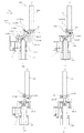
まず、図1乃至図4を用いて、本発明の一実施例を適用した、現像装置としての現像カートリッジB(以下、「カートリッジ」と称す。)について説明する。図1は、カートリッジBの断面図である。図2、3はカートリッジBの斜視図である。また、図4はカラー電子写真画像形成装置本体A(以下、「装置本体」と称す。)の断面図である。
(1) Description of Developing Cartridge (Developing Device) First, with reference to FIGS. 1 to 4, a developing cartridge B (hereinafter referred to as “cartridge”) as a developing device to which an embodiment of the present invention is applied. explain. FIG. 1 is a cross-sectional view of the cartridge B. 2 and 3 are perspective views of the cartridge B. FIG. 4 is a cross-sectional view of a color electrophotographic image forming apparatus main body A (hereinafter referred to as “apparatus main body”).
尚、このカートリッジBは、ユーザによって、装置本体Aに設けられたロータリCに対して、取付け、取り外しが可能である。 The cartridge B can be attached to and detached from the rotary C provided in the apparatus main body A by the user.
図1乃至図3において、カートリッジBは現像ローラ110を有する。現像ローラ110は、現像作用時に、装置本体Aから後述するカップリング機構により回転力を受けて回転する。
1 to 3, the cartridge B has a developing
現像剤収納枠体114には所定色の現像剤tが収納されている。この現像剤は、攪拌部材116が回転することによって、現像室113aに所定量搬送される。搬送された現像剤は、現像室113aにおいてスポンジ状の現像剤供給ローラ115の回転によって現像ローラ110表面に供給される。そして、この現像剤は、薄板状の現像ブレード112と現像ローラ110との摩擦により電荷を付与され薄層化される。薄層化された現像ローラ110上の現像剤は、回転により現像位置に搬送される。そして、現像ローラ110に所定の現像バイアスを印加することにより、電子写真感光体ドラム(以下、「感光体ドラム」と称す)107に形成された静電潜像が現像する。即ち、現像ローラ110によって、静電潜像が現像される。
A
また、前記静電潜像の現像に寄与しなかった現像剤、すなわち、現像ローラ110の表面に残留した現像剤は、現像剤供給ローラ115で剥ぎ取られる。またこれと同時に、供給ローラ115によって、新しい現像剤が現像ローラ110表面に供給される。これによって現像動作が連続的に行われる。
Further, the developer that has not contributed to the development of the electrostatic latent image, that is, the developer remaining on the surface of the developing
尚、現像カートリッジBは、現像ユニット119を有する。また、現像ユニット119は、現像枠体113と現像剤収納枠体114とを有する。また、現像ユニット119は、現像ローラ110、現像ブレード112、現像剤供給ローラ115、現像室113a、現像剤収納枠体114、及び、攪拌部材116を有する。
The developing cartridge B has a developing
尚、現像ローラ110は、軸線L1を中心に回転可能である。
The developing
ここで、前記現像カートリッジBは、ユーザーによって、装置本体Aの回転選択機構(現像ロータリ)Cに設けられた現像カートリッジ収容部130Aに取り付けられる。この際に、後述するように、カートリッジBが移動部材としての現像ロータリ(回転選択機構)Cにより所定の位置(感光体ドラム対向部)に位置決めされる動作に連動して、装置本体Aの駆動軸とカートリッジBの回転駆動力伝達部品であるカップリング部材とが結合する。そして、現像ローラ110等は装置本体Aから駆動力を受けて回転する。
Here, the developer cartridge B is attached to a developer
(2)電子写真画像形成装置の説明
図4を用いて、前述した現像カートリッジBを用いるカラー電子写真画像形成装置について説明する。尚、以下、カラー電子写真画像形成装置として、カラーレーザービームプリンターを例に挙げて説明する。
(2) Description of Electrophotographic Image Forming Apparatus A color electrophotographic image forming apparatus using the developing cartridge B described above will be described with reference to FIG. Hereinafter, a color laser beam printer will be described as an example of the color electrophotographic image forming apparatus.
図4に示すように、色の異なる現像剤(トナー)を収納した複数のカートリッジB(B1、B2、B3、B4)をロータリC上に取り付ける。尚、カートリッジBのロータリCに対する取付け、取り外しはユーザによって行われる。そして、ロータリCを回転することにより、所定色の現像剤を収納したカートリッジBを感光体ドラム107に対向させる。そして、感光体ドラム107に形成された静電潜像を現像する。現像された現像像を転写ベルト104aに転写する。さらに、これらの現像転写動作を各色について行う。これにより、カラー画像を得る。以下に詳細に説明する。ここで記録媒体Sは、画像を形成することができるものであって、例えば紙、OHPシート等である。
As shown in FIG. 4, a plurality of cartridges B (B1, B2, B3, B4) containing developers (toners) of different colors are mounted on the rotary C. Note that the attachment and removal of the cartridge B with respect to the rotary C is performed by the user. Then, by rotating the rotary C, the cartridge B containing the developer of a predetermined color is opposed to the
図4に示すように、光学手段101から画像情報に基づいた光を感光体ドラム107に照射する。これによって、感光体ドラム107に静電潜像を形成する。そして、この潜像は現像剤を用いて、現像ローラ110によって現像される。感光体ドラム107に形成された現像剤像は、中間転写体に転写される。
As shown in FIG. 4, the
次にその中間転写体である中間転写ベルト104a上に転写された現像剤像が、第二の転写手段によって記録媒体Sに転写される。そして、現像剤像が転写された記録媒体Sを、加圧ローラ105aと加熱ローラ105bを有する定着手段105に搬送する。そして、記録媒体Sに転写された現像剤像を記録媒体Sに定着する。定着後、記録媒体Sをトレイ106へ排出する。
Next, the developer image transferred onto the intermediate transfer belt 104a as the intermediate transfer member is transferred onto the recording medium S by the second transfer unit. Then, the recording medium S on which the developer image is transferred is conveyed to a
さらに画像形成工程を説明する。 Further, the image forming process will be described.
転写ベルト104aの回転と同期して感光体ドラム107を反時計回り(図4)に回転させる。そして、この感光体ドラム107表面を帯電ローラ108によって均一に帯電する。そして、光学手段101によって、画像情報に応じて、例えばイエロー画像の光照射を行う。そして、感光体ドラム107にイエロー色の静電潜像を形成する。
In synchronization with the rotation of the transfer belt 104a, the
露光手段は次のように構成される。露光手段101は外部装置(不図示)から読み込んだ画像情報に基づいて、感光体ドラム107に光照射を行う。これによって、感光体ドラム107に静電潜像を形成する。露光手段は、レーザーダイオード、及びポリゴンミラー、スキャナモータ、結像レンズ、反射ミラーを有する。
The exposure means is configured as follows. The
そして外部装置(不図示)から画像信号が与えられる。これによって、レーザーダイオードが前記画像信号に応じて発光し、ポリゴンミラーに画像光として照射する。このポリゴンミラーはスキャナモータによって高速回転し、前記ポリゴンミラーで反射した画像光が結像レンズ及び反射ミラーを介して前記感光体ドラム107の表面を選択的に露光する。これによって、感光体ドラム107に画像情報に応じた静電潜像を形成する。
Then, an image signal is given from an external device (not shown). As a result, the laser diode emits light according to the image signal and irradiates the polygon mirror as image light. The polygon mirror is rotated at a high speed by a scanner motor, and image light reflected by the polygon mirror selectively exposes the surface of the
この潜像の形成と同時にロータリーCを回転させる。これによって、イエローカートリッジB1を現像位置に移動させる。そして、現像ローラ110に所定のバイアス電圧を印加する。これによって、潜像にイエロー現像剤を付着させる。そして、潜像がイエロー現像剤によって現像される。その後、転写ベルト104aの押えローラ(一次転写ローラ)104jに現像剤と逆極性のバイアス電圧を印加する。これによって、感光体ドラム107上のイエローの現像剤像を中間転写ベルト104aに一次転写する。
Simultaneously with the formation of this latent image, the rotary C is rotated. As a result, the yellow cartridge B1 is moved to the developing position. Then, a predetermined bias voltage is applied to the developing
上述のようにイエロー現像剤像の一次転写が終了すると、ロータリーCが回転する。そして、次のカートリッジB2が移動し、感光体ドラム107に対向した位置に位置決めされる。以上の工程を、マゼンタカートリッジB2、シアンカートリッジB3、ブラックカートリッジB4の各カートリッジについて行う。このように、マゼンダ、シアン、そしてブラックの各色について繰り返すことによって、転写ベルト104a上に4色の現像剤像を重ね合わせる。
When the primary transfer of the yellow developer image is completed as described above, the rotary C rotates. Then, the next cartridge B2 moves and is positioned at a position facing the
尚、イエローカートリッジB1は、イエロー色の現像剤を収納しているものであり、イエロー現像剤像を形成する。マゼンタカートリッジB2は、マゼンタ色の現像剤を収納しているものであり、マゼンタ現像剤像を形成する。シアンカートリッジB3は、シアン色の現像剤を収納しているものであり、シアン現像剤像を形成する。ブラックカートリッジB4は、ブラック色の現像剤を収納しているものであり、ブラック現像剤像を形成する。 The yellow cartridge B1 contains a yellow developer and forms a yellow developer image. The magenta cartridge B2 contains a magenta developer and forms a magenta developer image. The cyan cartridge B3 contains a cyan developer and forms a cyan developer image. The black cartridge B4 contains a black developer, and forms a black developer image.
この間、二次転写ローラ104bは、転写ベルト104aとは非接触状態にある。この時、クリーニング帯電ローラ104fも転写ベルト104aとは非接触状態に位置する。
During this time, the
そして、転写ベルト104a上に4色の現像剤像が形成された後、転写ローラ104bが転写ベルト104aに圧接される(図4)。更に転写ローラ104bの圧接と同期して、レジストローラ対103e近傍の所定の位置で待機していた記録媒体Sが、転写ベルト104aと転写ローラ104bのニップ部に送り出される。そして、同時に記録媒体Sが搬送手段103としての給送ローラ103b、搬送ローラ対103cによってカセット103aから搬送される。
After four color developer images are formed on the transfer belt 104a, the
ここで、レジストローラ対103eの直前にはセンサ99が配置されている。センサ99は、記録媒体Sの先端を検知して、レジストローラ対103eの回転を停止し、記録媒体Sを所定の位置で待機させるものである。 Here, a sensor 99 is disposed immediately before the registration roller pair 103e. The sensor 99 detects the leading edge of the recording medium S, stops the rotation of the registration roller pair 103e, and waits the recording medium S at a predetermined position.
また、転写ローラ104bには、現像剤と逆極性のバイアス電圧が印加されている。これによって、転写ベルト104a上の現像剤像が、搬送されてきた記録媒体Sに一括して二次転写される。
A bias voltage having a polarity opposite to that of the developer is applied to the
現像剤像が転写された記録媒体Sは、搬送ベルトユニット103fを経由して定着手段105に搬送される。そして現像剤像の定着が行われる。そして、定着が行われた記録媒体Sは、排出ローラ対103gによって、装置本体上部の排出トレイ106に排出される。これによって、記録媒体Sに画像形成を完了する。
The recording medium S on which the developer image has been transferred is conveyed to the fixing
一方、二次転写終了後に帯電ローラ104fが転写ベルト104aに圧接される。これによって、ベルト104a表面及びベルト104a表面に残留した現像剤は、所定のバイアス電圧が印加される。そして残留電荷が除電される。 On the other hand, after completion of the secondary transfer, the charging roller 104f is pressed against the transfer belt 104a. As a result, a predetermined bias voltage is applied to the surface of the belt 104a and the developer remaining on the surface of the belt 104a. The residual charge is removed.
除電された残留現像剤は、一次転写ニップ部を介してベルト104aから感光体ドラム107へ静電気的に再転写される。これによって、ベルト104a表面がクリーニングされる。なお、感光体ドラム107に再転写された二次転写後の残留現像剤は、感光体ドラム107に接触しているクリーニングブレード117aによって除去される。
The discharged residual developer is electrostatically retransferred from the belt 104a to the
除去された現像剤は、搬送経路(不図示)をたどり、廃現像剤ボックス107dに回収される。
The removed developer follows a conveyance path (not shown) and is collected in a
尚、収容部130aは先に説明したカートリッジBが収納される部屋で、ロータリCに複数箇所設けられている。カートリッジBがこの部屋に取り付けられた状態で、ロータリCが一方向へ回転する。これによって、カートリッジBのカップリング部材(後述する)が、装置本体Aに設けられた駆動軸180に連結し及び駆動軸180から離脱する。ここで、カートリッジB(現像ローラ110)は、ロータリCの一方向への移動に応じて、駆動軸180の軸線L3方向と実質的に直交する方向に移動する。
The accommodating portion 130a is a room for accommodating the cartridge B described above, and is provided at a plurality of locations on the rotary C. With the cartridge B mounted in this room, the rotary C rotates in one direction. As a result, the coupling member (described later) of the cartridge B is connected to the
(3)現像ローラの構成
次に、図5を用いて、現像ローラの構成について説明する。図5(a)は、現像ローラ110を現像ローラ110が本体Aから駆動力を受ける側(以下単に「駆動側」と称す)から見た斜視図である。図5(b)は非駆動側(現像ローラの軸線方向において、駆動側とは反対側を「非駆動側」と称す)から見た斜視図である。
(3) Configuration of Developing Roller Next, the configuration of the developing roller will be described with reference to FIG. FIG. 5A is a perspective view of the developing
現像ローラ110は現像軸153、ゴム部110aを有する。
The developing
現像軸153は鉄等の導電性の細長い軸状であり、その軸方向中央部付近をゴム部110aで覆われている。また現像軸153は、両端の嵌合部153d1、153d2が、現像枠体113に軸受(不図示)を介して回転自在に支持されている。更に、後述するカップリング150が駆動側の端部153bに位置決めされている。カップリング150は、後述する回転力伝達ピン155と係合することにより、カップリング150から回転力を伝達される。
The developing
ゴム部110aは現像軸153と同軸となるように現像軸153に被覆されている。ゴム部110aは、現像剤を担持し、現像軸153にバイアスを印加されることにより、前記静電潜像を現像する。
The
ニップ幅規制部材136、137は現像ローラ110の感光ドラム107に対するニップ幅を一定に規制する部材である。
The nip
前記軸受(不図示)は、現像ローラ110の両端部153d1、153d2に配置され、現像枠体113(図1参照)に現像ローラ110を回転自在に支持している。
The bearings (not shown) are disposed at both ends 153d1 and 153d2 of the developing
現像ギア(不図示)は、現像ローラ110の駆動側の端部153d1に配置され、現像軸153に固定されている。そして、現像ギア(不図示)は、装置本体Aから現像ローラ110が受けた回転力を現像カートリッジBの他の回転部材(例えば、現像剤供給ローラ115、攪拌部材116等)に伝達する。
The developing gear (not shown) is disposed at the driving side end 153
次に、カップリング150を移動可能(傾動可能、揺動可能)に取り付ける現像軸153の駆動側の端部について詳細に説明する。その端部153bはカップリング150(後述する)の軸線L2が傾斜する際に滑らかに傾斜できるように球面形状である。また、現像軸153の先端近傍には、カップリング150から回転力を受けるために駆動力伝達ピン155が、現像軸153の軸線L1に対して交差する方向に配置されている。
Next, the drive-side end of the developing
回転力被伝達部としてのピン155は、金属製であり、現像軸153に対して圧入、或いは、接着等の方法で固定されている。その位置は駆動力(回転力)が伝達される位置(つまり、現像軸(現像ローラ)の軸線L1に対して交差する方向)であれば、どこでも良い。好ましくは、現像軸153の先端部153bの球面中心P2(図10b参照)を通る様に配置することが望ましい。なぜなら、現像軸153の軸線L1とカップリング150の軸線L2とが少し傾いた場合でも、常に回転力の伝達半径が一定となるからである。そのため、一定した回転力の伝達を実現できるからである。また、回転力伝達のポイントは何箇所でも良い。しかしながら、駆動トルク(回転力)を確実に伝達できるようにするため、及び、組立性を向上させるために、本実施例ではピン155を1本とした。また、ピン155は、先端球面153bの中心P2を通るように貫通させている。これにより、ピン155が、現像軸153の周面の180°相対する位置に突出するように配置した(155a1,155a2)。つまり、回転力は2ヵ所で伝達することとした。
The
尚、本実施例では、ピン155は、ドラム軸153の先端から5mm以内の先端側に取り付けられている。但し、これに限定されるものではない。
In this embodiment, the
尚、本体側現像電気接点(不図示)は、導電性である現像軸153の非駆動側端部153cと接触するように本体Aに配置されている。そして、現像カートリッジの有する電気接点(不図示)と本体側現像電気接点とが接触する。これにより、カートリッジBは装置本体Aと電気的に接続される。これによって、装置本体Aから高圧バイアスを現像ローラ110に供給している。
The main body side development electrical contact (not shown) is disposed on the main body A so as to come into contact with the non-driving
(4)回転駆動力伝達部品(カップリング、カップリング部材)の説明
次に、図6を用いて、本発明の主要な構成要素である回転駆動力伝達部品であるカップリング(カップリング部材)の一例について説明する。図6(a)はカップリングを装置本体側から見た斜視図であり、図6(b)はカップリングを現像ローラ側から見た斜視図である。また、図6(c)はカップリング回転軸l2方向に直交方向から見た図である。また、図6(d)はカップリングを装置本体側から見た側面図であり、図6(e)は現像ローラ側から見た図である。また、図6(f)は図6(e)をS3で切った断面図である。
(4) Explanation of Rotational Driving Force Transmission Parts (Coupling, Coupling Member) Next, referring to FIG. 6, a coupling (coupling member) which is a rotational driving force transmission part which is a main component of the present invention. An example will be described. FIG. 6A is a perspective view of the coupling as viewed from the apparatus main body side, and FIG. 6B is a perspective view of the coupling as viewed from the developing roller side. FIG. 6C is a view as seen from the direction orthogonal to the direction of the coupling rotation axis l2. 6D is a side view of the coupling as viewed from the apparatus main body side, and FIG. 6E is a view as viewed from the developing roller side. Moreover, FIG.6 (f) is sectional drawing which cut FIG.6 (e) by S3.
現像カートリッジBを装置本体Aに設けられたロータリC内のカートリッジ収容部130aに取り外し可能に取り付ける。これは、ユーザによって行われる。そして、ロータリCを回転駆動させ、カートリッジBが所定位置(感光体ドラム107と対向する位置、現像位置)に達した位置で、ロータリCを停止させる。これによって、カップリング(カップリング部材)150は、装置本体Aに設けられた駆動軸180と係合する。更に、ロータリCを一方向へ回転することによって、カートリッジBを前記所定位置(現像位置)から移動させる。即ち、所定位置から退避させる。これによって、カップリング150は、駆動軸180から離脱する。そして、カップリング150は、駆動軸180と係合した状態で、装置本体Aに設けられたモータ64(図17)から回転力を受ける。そして、その回転力を現像ローラ110に伝達する。これによって、現像ローラ110が装置本体Aから受けた回転力で回転する。
The developing cartridge B is removably attached to the cartridge accommodating portion 130a in the rotary C provided in the apparatus main body A. This is done by the user. Then, the rotary C is driven to rotate, and the rotary C is stopped at a position where the cartridge B reaches a predetermined position (position facing the
前述した通り、駆動軸180はピン182(回転力付与部)を有しており、モータ64により回転される。
As described above, the
尚、カップリング150の材質は、ポリアセタール、ポリカーボネート等の樹脂である。但し、カップリング150の剛性を上げるために、負荷トルクに応じて、樹脂にガラス繊維等を配合して剛性を上げても良い。また、金属材料を使用しても良い。その材質は、適宜選択可能である。但し、樹脂であれば加工が行い易いため、本実施例の各カップリングは樹脂製である。
The material of the
カップリング150は主に3つの部分を有する。まず第一の部分は、図6(c)に示すように、駆動軸180(後述する)と係合するものである。そして、この駆動軸180に設けられた回転力付与部(本体側回転力伝達部)である回転力伝達ピン182から回転力を受けるための被駆動部150aである。また第二の部分は、現像軸153に設けられたピン155に係合して、現像ローラ110に回転力を伝える駆動部150bである。また、第三の部分は、被駆動部150aと駆動部150bとをつなぐ中間部150cである。
The
図6(f)に示すように、被駆動部150aは、回転軸線L2に対して広がった駆動軸挿入開口部150mを有する。また、駆動部150bは、現像軸挿入開口部150lを有する。
As shown in FIG. 6F, the driven
開口部150mは、駆動軸180(図9乃至図13)側に向かって拡開した円錐形状の駆動軸受け面150fにより形成されている。受け面150fは、図6(f)に示すように凹部150zを構成している。尚、凹部150zは、軸線L2方向において、現像ローラ110の設けられた側とは反対側に開口部150m(開口)を有する。
The
これにより、現像ローラ110のカートリッジB内での回転位相に関わらず、駆動軸180の先端部182aに阻止されることなく、カップリング150が駆動軸180の軸線L3に対して係合前角度位置(図22(a))、回転力伝達角度位置(図22(d))、及び、離脱角度位置(図25(c)(d))間を移動(傾動)できる。尚、詳細は後述する。
As a result, the
そして、凹部150zの端面であって、軸線L2を中心とする円周上には、複数個の突起(突出部)(係合部)150d(150d1〜d4)が等間隔に配置されている。また、各々の突起150dの間には、進入部150k(150k1、150k2、150k3、150k4)が設けられている。ここで、隣り合う突起150d1〜d4の間隔は、この間隔内に、駆動軸180に設けられた回転力伝達ピン(回転力付与部)182が位置できるように、ピン182の外径よりも大きく設定されている。尚、ピン182が回転力伝達部である。この隣り合う突起の間が、進入部150k1〜k4である。カップリング150に駆動軸180から回転力が伝達される際にには、進入部150k1〜k4にいずれかにピン182が位置する。更に、図6(d)において、各突起150dの時計周りの方向(図示X1)において、上流側には、回転力受面(回転力受け部)150e(150e1〜150e4)が設けられている。この回転力受面150eは、カップリング150の回転方向と交差して設けられている。即ち、突起150d1には受け面150e1、突起150d2には受け面150e2、突起150d3には受け面150e3、及び、突起150d4には受け面150e4が設けられている。駆動軸180が回転している状態では、ピン182a1、182a2が、受け面150eのいずれかに接触する。これによって、ピン182a1、182a2が接触している受け面150eがピン182に押される。これによって、カップリング150は、軸線L2を中心にして回転する。
A plurality of protrusions (protruding portions) (engaging portions) 150d (150d1 to d4) are arranged at equal intervals on the end surface of the
尚、カップリング150に伝達される伝達トルクをできるだけ安定させるために、回転力受け面150eは軸線L2上に中心Oを有する仮想円上(同一円周上)C1に配置されていることが望ましい(図6(d))。これにより、回転力伝達半径が一定となり、伝達されるトルクが安定する。また、突起150dは、カップリング150の受ける力の釣り合いにより、カップリング150の位置ができるだけ安定する方が好ましい。そのため本実施例では、各受け面150eを180°対向した位置に配置している。即ち、本実施例では、受け面150e1と受け面150e3及び受け面150e2と受け面150e4を対向させて対で構成している。なぜなら、180°でもって対向した位置に配置することにより、カップリング150の受ける力は偶力となる。そのため、カップリング150は偶力を与えるだけで回転運動を続けることができる。そこで、回転軸線L2の位置を規定しなくとも、カップリング150は回転することができるからである。
In order to stabilize the transmission torque transmitted to the
また、その設置個数は、駆動軸180のピン182(回転力付与部)が進入部(窪み、以下進入部と称す)150k(150k1〜150k2)に挿入できる程度に空いていれば、適宜の数選択できる。本実施例では、図6に示すように4本とした。尚、本実施例はこれに限定されるものではない。例えば、受け面150e(突起部150d1〜150d4)が同一円周上(仮想円C1 図6(d))に配置されていない場合であっても、或いは、180°対向した位置に配置されていない場合であっても構わない。しかしながら、受け面150eを前述した配置とすることによって、前述した効果を得ることができる。
Further, the number of the installed shafts may be an appropriate number as long as the pins 182 (rotational force applying portions) of the
ここで、本実施例の場合には、前記ピン182の直径を約2mmとした。この場合に、進入部150kの周長は、約8mmとした。尚、進入部150kの周長とは、隣り合う突起150dの円弧上(仮想円上)の間隔である。但し、これに限定されるものではない。
Here, in the present embodiment, the diameter of the
また、開口部150mと同様に、現像軸挿入開口部150lは、現像軸153側に向かって広がった拡開部としての円錐形状の回転力受け面150iを有する。受け面150iは、図6(f)に示すように凹部150qを構成している。
Similarly to the
これによって、カートリッジB内での現像ローラ110の回転位相がどこであっても、現像軸153の先端部に阻止されることなく、カップリング150が軸線L1に対して、回転力伝達角度位置、係合前角度位置、及び、離脱角度位置の間を移動できる(傾動できる、揺動できる)。図示例では、凹部150qは、軸線L2を中心とする円錐形状の受け面150iにより構成されている。そして、受け面150iに、待機開口部150g1、150g2(以下単に「開口部」と称す)が設けられている(図6(b)参照)。カップリング150は、この開口部150g1、150g2内にピン155が位置できるように、現像軸153に取り付けられる。そして、開口部150g1、150g2の大きさは、ピン155の外径よりも大きくなっている。これによって、カートリッジB内での現像ローラ110の回転位相がどこであっても、ピン155に阻止されること無く、カップリング150が後述する回転力伝達角度位置、係合前角度位置(または、離脱角度位置)の間を移動できる(傾動できる、揺動できる)。
As a result, regardless of the rotational phase of the developing
即ち、突起150dは、凹部150zの先端側に設けられている。そして、突起(突出部)150dは、カップリング150が回転する回転方向と交差する交差方向に突出して、及び、前記回転方向に沿って間隔をあけて複数個設けられている。
That is, the
そして、受け面150eは、カートリッジBがロータリーCに取り付けられた状態で、ピン182と係する。そして、回転する駆動軸180から力を受けるピン182によって押される。これによって、受け面150eは、駆動軸180からの回転力を受ける。また、受け面150eは、軸線L2から等距離に、及び、軸線L2を挟んで対になって位置するように、各突起150dにおいて、前記交差方向に設けられた面に設けられている。
The receiving
また、進入部(窪み)150kが、前記回転方向に沿って、及び、軸線L2方向に窪んで設けられている。この、進入部150kは、突起150dと突起150dとの間に設けられている。尚、駆動軸180が回転を停止している場合に、カートリッジBがロータリーCに取り付けられた状態で、カップリングが駆動軸180と係合すると、ピン182が進入部150kに進入する。そして、回転する駆動軸180のピン182によって、受け面150eが押される。あるいは、カップリングが駆動軸180と係合する際に、駆動軸180が既に回転している場合には、ピン182が進入部150kに進入して、ピン182が受け面150eを押す。これによって、カップリング150が回転する。尚、回転力受け面(回転力受け部)150eは、駆動軸受け面150fの内側に配置されていても良い。或いは、受け面150eは、軸線L2方向において、受け面150fから外方へ突出した箇所に配置されていても良い。受け面150eが、受け面150fの内側に配置されている場合には、進入部150kも受け面150fの内側に配置される。即ち、進入部150kは、受け面150fの円弧部の内側で、且つ、突起150d間に位置する窪みである。また、受け面150eが、前記外方へ突出した箇所に配置されている場合には、進入部150kは、突起150d間に位置する窪みである。尚、ここで、窪みとは、軸線L2方向において、貫通している穴であっても、或いは、底部を有している場合であっても含まれる。即ち、窪みとは、突起150d間に位置している空間領域であれば良い。そして、カートリッジBがロータリCに取り付けられた状態で、前記領域に、ピン182が進入できればよい。
Moreover, the entrance part (dent) 150k is provided so as to be recessed along the rotation direction and in the direction of the axis L2. The
前記構成は、後述する各実施例においても同様である。 The above-described configuration is the same in each embodiment described later.
また、図6(e)において、開口部150g1、150g2の反時計周り方向(図示X2)において上流側には、回転力伝達面(回転力伝達部)150h(150h1、150h2)が設けられている。そして、伝達面150h1、150h2が、ピン155a1、155a2と接触することにより、カップリング150から現像ローラ110に回転力が伝達される。即ち、伝達面150h1、150h2が、接触しているピン155の側面を押す。これによって、カップリング150が軸線L2を中心にして回転する。尚、伝達面150h1、150h2は、カップリング150の回転方向と交差した方向に設けられている。
Further, in FIG. 6E, a rotational force transmission surface (rotational force transmission portion) 150h (150h1, 150h2) is provided on the upstream side in the counterclockwise direction (X2 in the drawing) of the openings 150g1, 150g2. . Then, when the transmission surfaces 150h1 and 150h2 come into contact with the pins 155a1 and 155a2, the rotational force is transmitted from the
尚、突起150dと同様に、伝達面150h1、150h2は、同一円周及び180°対向に配置されていることが望ましい。
In addition, like the
また、カップリング部材150を射出成形によって製造する場合には、中間部150cが細くなることがある。その理由は、被駆動部150a、駆動部150b、中間部150cが略均等な肉厚となるようにしているからである。しかしながら、中間部150cの剛性が不足しているようであれば、中間部150cを太くすることも可能である。
Further, when the
(5)支持部材の形状
次に、図7を用いて、支持部材(取付け部材)157について説明する。図7(a)は駆動軸側から見た斜視図であり、図7(b)は現像ローラ側から見た斜視図である。
(5) Shape of Support Member Next, the support member (attachment member) 157 will be described with reference to FIG. 7A is a perspective view seen from the drive shaft side, and FIG. 7B is a perspective view seen from the developing roller side.
支持部材157はカップリング150を保持し、現像カートリッジBをロータリCに位置決めするための部材である。更には、支持部材157は、現像ローラ110に回転力を伝達可能なように、カップリング150を支持する機能を有している。即ち、支持部材157は、カップリング150をカートリッジBに取り付けるものである。
The
更に詳細に説明する。図7に示すように、支持部材157には、ロータリCに設けられた収容部130aにカートリッジBを着脱する際のガイド140L2及び、収容部130aにカートリッジBを位置決めするための円筒140L1を有している。また、現像ローラ(不図示)と同軸に設けられた円筒部157cの内側空間157bには、先に説明したカップリング150が配置される。また、空間157bを形成する内側周面157iには、カップリング150をカートリッジBから外れないようにする為のリブ157e1、157e2が設けられている。リブ157e1、157e2は現像カートリッジBの移動方向X4(ロータリC回転方向)に対して直交する方向に、相対して設けられている。更に、支持部材157には、現像枠体113に固定するための位置決め部157d1、157d2と、固定ビスを通す穴157g1、157g2が設けられている。
Further details will be described. As shown in FIG. 7, the
(6)カップリングのカートリッジ枠体への支持構成
次に、図8〜図13を用いて、現像ローラ110、及び、カップリング150の現像枠体(カートリッジ枠体)113に対する支持構成(取付け構成)について説明する。図8はカートリッジの現像ローラ周辺の要部について、駆動側から見た拡大図である。図9は図8のS4−S4で切った断面図である。図10はカップリング、及び、支持部材を組み付ける前に、現像軸線L1で切った断面図である。図11は図10を組み付けた状態の断面図である。図12は図9の状態からカップリングの軸線L2を現像ローラの軸線L1と略同軸線にした時の断面図である。図13は図12のカップリング及び現像ローラを90°回転させた断面図である。図14は現像軸とカップリングの結合状態を表した斜視図である。図14(b1)〜(b5)は斜視図であり、図14(a1)〜(a5)は(b1)〜(b5)夫々に対して、軸線L1方向から見た図である。
(6) Supporting structure for coupling to cartridge frame Next, referring to FIGS. 8 to 13, a supporting structure (mounting structure) for the developing
図14に示すように、軸線L2が現像軸(現像ローラ)153の軸線L1に対して、どのような方向にも傾斜できるように取付けられている。 As shown in FIG. 14, the axis L <b> 2 is attached so as to be inclined in any direction with respect to the axis L <b> 1 of the developing shaft (developing roller) 153.
図14(a1)(b1)では、軸線L2は現像ローラ153の軸線L1と同軸線上にある。この状態から、カップリング150を上向きに傾斜させたときの図を図14(a2)(b2)に示した。この図に示すように、軸線L2が開口部150gの方向へ傾斜するとき、カップリングを基準として相対的に見ると、ピン155は開口部150g内を移動する。その結果、カップリング150は開口部150gと直交する軸AX(図14(a2))を中心にして傾斜する。
In FIGS. 14A1 and 14B1, the axis L2 is coaxial with the axis L1 of the developing
図14(b3)は、カップリング150を右向きに傾斜させた状態を示している。この図に示すように、軸線L2が開口部150gの直交方向へ傾斜しているとき、カップリングを基準として相対的に見ると、ピン155は開口部1510gの中で回転する。回転する軸は伝達ピン155の中心軸AY(図14(a3))である。
FIG. 14 (b3) shows a state in which the
カップリング150を下向きに傾けた状態および左向きに傾けた状態を、それぞれ図14(a4)(b4)および図14(a5)(b5)に示す。カップリング150は各々、回転軸AX、AYを中心に傾斜する。
FIGS. 14 (a4), (b4) and FIGS. 14 (a5), (b5) show the state in which the
また、ここで説明した傾斜方向と異なる方向、例えば図14(a2)(a3)の傾斜方向の中間位置、及び、(a3)と(a4)、(a5)と(a2)の各傾斜方向中間位置では、回転軸AXとAYそれぞれの方向への回転が合算されて傾斜可能となる。このように、軸線L1に対して、軸線L2はどのような方向にも傾斜することができる。 Further, in the direction different from the inclination direction described here, for example, the intermediate position in the inclination direction of FIGS. 14 (a2) and (a3), and the intermediate positions in the inclination directions of (a3) and (a4), (a5) and (a2). At the position, the rotations in the respective directions of the rotation axes AX and AY are added together and can be tilted. Thus, the axis L2 can be inclined in any direction with respect to the axis L1.
この時、ピン155は現像軸153に設けられている。即ち、ピン155はその円周面から突出している。そして、ピン155に対向するカップリング150には開口150gが設けられている。開口150gは、軸線L2が軸線L1に対して傾斜する際に、ピン155が干渉しないように、開口150gの大きさを設定している。
At this time, the
即ち、伝達面(回転力伝達部)150hとピン(回転力被伝達部)155前記とは可動状態である(図14)。そして、カップリング150の回転方向において、伝達面150hとピン155は係合する。また、伝達面150hとピン155との間に隙間を有している。これによって、カップリング150は、軸線L1に対して実質的に全方向にわたって移動可能(傾動可能、揺動可能)である。即ち、カップリング150は、現像ローラ110の軸線L1に対して実質的に旋回可能である。
That is, the transmission surface (rotational force transmitting portion) 150h and the pin (rotational force transmitted portion) 155 are movable (FIG. 14). Then, in the rotation direction of the
尚、上記に軸線L2は軸線L1に対してどのような方向にも傾斜可能であると述べたが、必ずしも360°全ての方向に傾斜可能である必要はない。その場合、例えば、開口150gを円周方向に広めに設定おけば、軸線L2が軸線L1に対して傾斜する際、所定の角度傾斜できない場合でも、カップリング150が軸線L2まわりに少し回転して、所定の角度まで傾斜することができる。
Although it has been described above that the axis L2 can be tilted in any direction with respect to the axis L1, it is not necessarily tiltable in all directions of 360 °. In this case, for example, if the
ここで、旋回とは、カップリングの軸線L2の周りにカップリング自身が回転するのではなくて、傾斜した軸線L2が現像ローラ110の軸線L1の周りに回転することである。但し、遊び或いは積極的に設けた間隙の範囲で、軸線L2の周りにカップリング自身が回転することを排除しない。
Here, the turning means that the inclined axis L2 rotates around the axis L1 of the developing
また、実質的に全方向にわたって移動可能とは、使用者が、カートリッジBを装置本体Aに取り付ける際に、回転力付与部を有する駆動軸がどのような位相で停止していたとしても、カップリングが回転力伝達角度位置まで移動することができる範囲を意味する。 また、カップリングを駆動軸から離脱する際に、前記駆動軸がどのような位相で停止していたとしても、カップリングが前記離脱角度位置まで移動することができる範囲を意味する。 In addition, the fact that the user can move substantially in all directions means that when the user attaches the cartridge B to the apparatus main body A, no matter what phase the drive shaft having the rotational force applying portion stops, the cup It means a range in which the ring can move to the rotational force transmission angular position. Further, it means a range in which the coupling can move to the separation angle position when the coupling shaft is detached from the driving shaft, no matter what phase the driving shaft stops.
また、前記カップリングは、軸線L1に対して実質的に全方向にわたって傾斜可能なように、前記回転力伝達部(例えば、回転力伝達面150h)と前記回転力伝達部と係合する回転力被伝達部(例えば、ピン155)との間に隙間を有している。このように、前記カップリングは、カートリッジBの端部に取り付けられている。従って、前記カップリングは、軸線L1に対して実質的に全方向にわたって移動可能である。
In addition, the rotational force that engages the rotational force transmitting portion (for example, the rotational
尚、この構成は、後述するカップリングの各実施例においても、同様である。 This configuration is the same in the coupling embodiments described later.
次に、組み付け手順について述べる。 Next, the assembly procedure will be described.
現像ローラ110を現像枠体113に回転自在に取付けた後、ピン155を現像軸153に取り付ける。その後、現像ギア145を現像軸153に組み付ける。その後、図10に示すように、X3方向に、カップリング150及び支持部材157を現像軸153に挿入する。まず、カップリング150の軸線L2をX3と平行に、駆動部150bをX3方向下流側に向けて挿入する。この時、現像軸153側のピン155の位相と、カップリング150の開口150gの位相を合わせる。そして、ピン155を開口部150g1、150g2に潜り込ませる。そして、現像軸153の先端部153bをカップリング150の受け面150iに突き当てる。現像軸153の先端部153bは球面であり、カップリング150の受面150iは円錐面である。そのため、カップリング150の駆動部150b側は現像軸153の先端部153bの中心(球面中心)で位置が決まる。後述するが、装置本体Aから駆動力(回転力)を伝達されたカップリング150が回転すると、開口150gに位置するピン155が回転力伝達面150h1、150h2(図6b参照)に接接する。これによって、回転力の伝達が可能となる。
After the developing
その後、支持部材157の一方の端面157wをX3方向下流に向けて挿入すると、支持部材157の空間部157bにカップリング150の一部が内包される。そして、像支持部材157を現像枠体113に固定し、現像カートリッジBとして一体化される。
Thereafter, when one
ここで、カップリング150まわりの寸法関係について述べる。図10に示すように、カップリング150の被駆動部150aの最大外径をφD2、駆動部150bの最大外径をφD1、開口150gの最大径をφD3とする。また、ピン155の最大外径をφD5、支持部材157の抜け止めリブ157eの内径をφD4とする。尚、ピン155の最大外径φD1とは、現像ローラ110の回転軸線L1を中心とした時の最大回転軌跡の外径を示す。また、カップリング150に関する最大外径φD1、φD3とは、軸線L2を中心とした時の、最大回転軌跡の外径を示す。この時、φD5<φD3の関係が成り立てば、カップリング150をX3方向に真直ぐ組み付けるのみで所定の位置まで組むことができる。したがって、組立性が向上する。また、抜け止めリブ157eの内径φD4は、カップリング150のφD2よりも大きく、φD1よりは小さく設定する(すなわち、φD2<φD4<φD1)。これによって、支持部材157はX3方向に真直ぐ組み付けるのみで、所定の位置に組むことができる。したがって、組立性向上を図ることが出来る(組み付け後は図11参照)。
Here, the dimensional relationship around the
次に、図11に示すように、支持部材157の抜け止めリブ157eとカップリング150のつば部150jとは、軸線L1方向において近接して配置されている。具体的には、軸線L1方向において、つば部150jの一端面から、ピン155の軸線までの距離をn1とする。また、リブ157eの一端面から、つば部150jの他端面までの距離をn2とする。この時、距離n2<距離n1となるように設定している。
Next, as shown in FIG. 11, the retaining
また、軸線L1の直交方向に対して、つば部150jとリブ157e1、157e2とはオーバラップするように配置している。具体的には、軸線L1の直交方向に対して、リブ157eの内周面157e3と、つば部150jの外周面150j3とのオーバラップ量をn4としている。
Further, the
これらの設定により、ピン155がカップリング150の開口150gから外れることは無くなり、カップリング150がカートリッジBから外れることを防止できる。しかも、部品を格別追加することなく簡単におこなう事ができる。尚、これまで述べた寸法関係は組立性向上、コストダウンのために好ましい寸法関係であるが、組立方法を変えれば別の寸法関係でも構わない。
With these settings, the
先に説明したように(また、図9、図12に示すように)、カップリング150の受面150iが現像軸153の先端面153bに接触している。そのため、カップリング150は先端部(球面)153bの中心P2を回動中心に、先端部(球面)153b上を沿うように支持されている。つまり、現像軸153の位相に関わらず、カップリング150の軸線L2は傾斜可能に取り付けられている。即ち、図9、図11、図12に示すように、カップリング150の凹部150qである受面150iが、現像軸153の先端面153bに接触している。そのため、カップリング150は先端部(球面)153bの中心P2を回動中心にして、先端部(球面)153b上を沿うように揺動する。つまり、ドラム軸153の位相に関わらず、軸線L2は実質的に全方向にわたって移動可能に取り付けられている。即ち、カップリング150は、軸線L2が実質的に全方向にわたって移動可能(傾動可能、旋回可能、揺動可能)である。
As described above (as shown in FIGS. 9 and 12), the receiving
また、後述するが、カップリング150が駆動軸180に係合するためには、係合直前において、軸線L2は軸線L1に対して、ロータリCの回転方向において下流側に傾斜している必要がある。つまり、図17に示すように、カップリング150の被駆動部150aの位置が、ロータリCの回転方向X4において下流側に位置することが必要である。
As will be described later, in order for the
次に詳細に述べる。 Next, it will be described in detail.
まず、図11に示すように、カップリング150の駆動部150bの最大外径部と現像支持部材157の距離n3は、僅かに隙間が空くように設定されている。これによって、カップリング150が傾斜可能である。
First, as shown in FIG. 11, the distance n3 between the maximum outer diameter portion of the driving
また、図7に示すように支持部材157のリブ157e1、157e2は軸線L1方向に平行なリブである。また、リブ157e1、157e2は回転方向X4に直交するように配置されている。また、軸線L1方向における、リブ157eからつば部150jまでのの距離n2(図11参照)は、ピン155中心から駆動部150bの側端面までの距離n1よりも短く設定している。これによって、ピン155が開口150g1、150g2から外れることが無い。そのため、図9に示すように、カップリング150の軸線L2に対して、被駆動部150a側がX4方向に大きく傾斜可能となる。言い換えれば、リブ157eが配置されていない方向(図11で、紙面と垂直な方向)に、駆動部150b側が大きく傾斜可能である。図9には、軸線L2が傾斜した後の状態を示す。また、カップリング150は、図9に示す軸線L2が傾斜した状態から、図12に示す軸線L1と略平行な状態に移動することも自在である。このように、リブ157e1、157e2を配置する。これによって、カップリング150は、軸線L2が軸線L1に対して傾斜可能となること、及び、現像枠体113からカップリング150が外れるのを防止することができる。即ち、これらを、両立することができる。
Further, as shown in FIG. 7, the ribs 157e1 and 157e2 of the
尚、カップリング150は現像軸153に対して、軸線L1方向にがた(図12において距離n2)を有している。そのため、常にカップリング150の受面150i(円錐面)が先端部153b(球面)に沿わないことも予測される。従って、軸線L2の傾斜が球面中心P2を中心とした回動でない場合がある。しかし、このような回動(傾動)であっても、軸線L2が軸線L1に対して傾斜するために問題はない。
The
また、軸線L1と軸線L2の最大傾斜可能角度α(図9)は、軸線L2に対して、受け面150iのなすテーパ角α1(図6(f)に図示)の半分に規制される。つまり、カップリング150の受面150iの円錐の頂角を適宜選択する。これにより、カップリング150の傾斜角度αを最適な値にすることができる。これにより、現像軸153の円柱部153aは単純な円筒形状にすることができる。したがって、加工コストのアップを防ぐことができる。
Further, the maximum tiltable angle α (FIG. 9) between the axis L1 and the axis L2 is restricted to half the taper angle α1 (shown in FIG. 6F) formed by the receiving
先に、軸線L2が傾斜した時、ピン155が干渉しないよう、ピン155が待機する開口150gの広さを設定すると述べた。また、図13には、カップリング150の被駆動部150a側がX5方向に傾斜した時のつば部150jの軌跡を領域T1と図示した。図に示すように、カップリング150が傾斜しても、ピン155と干渉することなく、カップリングの全周に渡ってつば部150jを設けることができる(図6(b)参照)。つまり、受面150iを円錐形状にすることにより、カップリング150が傾斜する際に、ピン155が領域T1内に入らなくて済む。従って、カップリングを切り欠く範囲を最小限にすることができる。そのため、カップリングの剛性を確保することができる。尚、凹部150zは、カップリング150が駆動軸180から回転力を受ける状態では、駆動軸180の先端にかぶさる。また、凹部150zは、カップリング150の先端に、且つ、カップリング150の回転軸線L2上に設けられている。
Previously, it was described that the size of the
(7)装置本体のロータリ(移動部材、回転選択機構)の構成の説明
次に、図15乃至図21を用いて、移動部材としてのロータリーの構成について説明する。図15、図16は、現像カートリッジBが装着されていない状態のロータリーCの斜視図である。図17はひとつの現像カートリッジがロータリーCに装着された状態を表した斜視図である。図18乃至図21はロータリC、感光体ドラム107、駆動列、現像カートリッジBを側面から表した図である。
(7) Description of Configuration of Rotary (Moving Member, Rotation Selection Mechanism) of Device Main Body Next, a configuration of a rotary as a moving member will be described with reference to FIGS. 15 to 21. 15 and 16 are perspective views of the rotary C in a state where the developing cartridge B is not mounted. FIG. 17 is a perspective view showing a state where one developing cartridge is mounted on the rotary C. FIG. 18 to 21 are views showing the rotary C, the
軸線L1方向において、両端にロータリフランジ50L、50Rが設けられている。また、軸線L1方向の外方には、夫々ロータリ側板54L、54Rが設けられている。そして、フランジ50L、50Rとその中心軸51は、軸線L1方向の一番外側に位置する側板54L、54Rに支えられて回転可能に支持されている。
一対のフランジ50L、50Rの対向面50Lb、50Rbには、カートリッジBをロータリC(収容部130A)に着脱する際の溝状の本体ガイド130L1、130L2、130L3、130L4、130R1、130R2、130R3、130R4が設けられている。そして、カートリッジBの有するカートリッジ側ガイド140R1、140R2、140L1、140L2(図2、図3)が、装置本体Aに設けられた前記本体ガイドに沿って挿入される。つまり、カートリッジBはロータリCに着脱自在である。即ち、カートリッジBは、ユーザによって、ロータリCに取り外し可能に取り付けられる。
On the opposing surfaces 50Lb and 50Rb of the pair of
具体的に説明する。カートリッジB(B1)の長手方向一端にはガイド140R1、140R2が設けられている。また、カートリッジBの長手方向他端にはガイド140L1、140L2が設けられている。そして、使用者がカートリッジBをつかんで、ガイド140R1、140R2をロータリCに設けられたガイド130R1に挿入する。同じく、ガイド140L1、140L2をロータリCに設けられたガイド130L1に挿入する。このように、使用者によってカートリッジBが、ロータリCに設けられた収容部130Aに取り外し可能に装着される。即ち、カートリッジBは、前記ガイドに案内されて、収容部130Aに対して、カートリッジB(現像ローラ110)の長手方向と交差する方向に着脱される。したがってカートリッジBは、収容部130Aに対して、ロータリCの回転方向X4に対して前記長手方向が交差する方向に取り付けられる。よって、カートリッジBの長手方向一端に設けられたカートリッジB(カップリング)は、ロータリCの回転に応じて、駆動軸180と実質的に直交する方向に移動する。また、ロータリCに取り付けられたカートリッジB)は、装置本体Aから回転力が伝達された際に、円弧形状のガイド140R1、140L1を中心にして回転しようとする。しかしながら、細長形条のガイド140R2、140L2がガイド130R1、ガイド130L1の溝の内面に接触する。これによって、カートリッジBは、ロータリCに対して位置が決まる。即ち、カートリッジBは、収容部130Aに取り外し可能に収容される。
This will be specifically described. Guides 140R1 and 140R2 are provided at one end in the longitudinal direction of the cartridge B (B1). Further, guides 140L1 and 140L2 are provided at the other longitudinal end of the cartridge B. Then, the user grasps the cartridge B and inserts the guides 140R1 and 140R2 into the guide 130R1 provided on the rotary C. Similarly, the guides 140L1 and 140L2 are inserted into the guide 130L1 provided on the rotary C. In this way, the cartridge B is detachably mounted by the user in the
同様に、カートリッジB(B2)が、ロータリCに設けられたガイド130R2、130L2にガイドされて、収容部130Aに取り外し可能に装着される。また、カートリッジB(B3)が、ロータリCに設けられたガイド130R3、130L3にガイドされて、収容部130Aに取り外し可能に装着される。またカートリッジB(B4)が、ロータリCに設けられたガイド130R4、130L4にガイドされて、収容部130Aに取り外し可能に装着される。
Similarly, the cartridge B (B2) is guided by guides 130R2 and 130L2 provided on the rotary C, and is detachably mounted in the
即ち、各カートリッジBは、使用者によって、ロータリCに設けられた収容部130Aに取り外し可能に収容される。
That is, each cartridge B is detachably accommodated in the
図17に現像カートリッジBが装置本体A(ロータリC)に取り付けられた状態を示す。 FIG. 17 shows a state in which the developing cartridge B is attached to the apparatus main body A (rotary C).
尚、夫々の現像カートリッジBはロータリCに対して位置が決まり、ロータリCが回転することにより現像カートリッジBも回転する。この時、ロータリCの回転により、現像カートリッジBの位置がずれないように、現像カートリッジBはロータリCに対して、付勢バネまたは、ロック等(不図示)で固定されている。 Each developing cartridge B is positioned with respect to the rotary C, and when the rotary C rotates, the developing cartridge B also rotates. At this time, the developing cartridge B is fixed to the rotary C with an urging spring or a lock (not shown) so that the position of the developing cartridge B does not shift due to the rotation of the rotary C.
一方のロータリ側板54Lには、現像ローラ(不図示)を回転するために駆動機構が設けられている。即ち、現像駆動ギア181が、モータ64のモータ軸に固定されたピニオン65と噛合っている。そして、モータ64が回転を始めると、ギア181に回転力が伝達される。そして、ギア181と同軸に配置されている駆動軸180が回転を開始する。これによって、駆動軸180の回転力が、カップリング150を介して現像ローラ110等に伝達される。尚、本実施例においては、駆動軸180は、カップリング150が係合する前から回転を開始している。
One
しかしながら、駆動軸180が回転を開始するタイミングは、適宜選択できる。
However, the timing at which the
また、カートリッジBは、一対のロータリフランジ50L、50Rと共に回転する。即ち、ロータリCは、所定角度回転すると回転を停止する。これにより、カートリッジBは、装置本体Aに設けられた感光ドラム107と対向する位置(現像位置)に位置決めされる。カートリッジBが、位置決めされて停止するのとほぼ同時に、カップリング150が駆動軸180と係合する。即ち、凹部150zが駆動軸180の先端部180b先端にかぶさる。これによって、回転力の伝達が安定して行われる。
Further, the cartridge B rotates together with the pair of
これが、凹部150zを設けた効果である。
This is the effect of providing the
駆動軸180は先に説明した現像軸とほぼ同様な構成である。つまり、先端部180bを球面とし、また円筒形状の主部180aのほぼ中心を貫くピン182を有している。そして、ピン182により、カップリング150を介し、カートリッジBに回転力(駆動力)を伝達している。
The
ロータリCには、4色のカートリッジBが取り付けられる。ここで、カートリッジBの感光体ドラム107に対する加圧は以下のように行っている。
Four-color cartridges B are attached to the rotary C. Here, the pressurization of the cartridge B to the
前述した通り、フランジ50L、50Rはロータリ側板54L、54Rに対して回転可能に支持されている。そして、両側端のロータリ側板54L、54Rは、その上部に回動可能に配置された揺動軸60によって装置本体Aの側板(不図示)に位置決め固定されている。言い換えると、カートリッジBとロータリフランジ50およびロータリ側板54はこれらが一体となって、揺動軸60を中心として揺動する。即ち、カートリッジBとロータリCが一体となった揺動運動をする。これによって、カートリッジBは感光体ドラム107に対して加圧または離間される。
As described above, the
尚、上記離間の動作は、揺動可能なロータリ側板54Lをカム(不図示)の回転で押し上げることにより行われる。
The above-described separation operation is performed by pushing up the swingable
また、図15で図した通り、駆動軸180は、径方向、及び、軸方向に位置決めされて設置されている。また、カートリッジBも、ロータリCの回転停止によって、位置決めされる。そして、前記所定位置に位置決めされた駆動軸180と、同じく前記所定位置に位置決めされたカートリッジBの両者を、カップリング150が連結する。カップリング150はカートリッジB(枠体)に対して揺動可能(傾動可能、移動可能)な構成である。従って、上述のように所定位置に位置決めされた駆動軸180と、同じく所定位置に位置決めされたカートリッジBとの間であっても、カップリング150は円滑に回転力を伝達できる。つまり、駆動軸180とカップリング150との間に、多少の軸ずれがあったとしても、カップリング150は円滑に回転力を伝達できる。
Further, as illustrated in FIG. 15, the
これは、本発明を適用したカップリングの実施例の顕著な効果の一つである。 This is one of the remarkable effects of the embodiment of the coupling to which the present invention is applied.
(8)現像カートリッジ(現像装置)の切換構成
フランジ50L、50Rの外周面には、図15乃至図17に示すように、ギア50aが一体に設けられている。そして、これと噛合う一対のアイドラギア59L、59Rが長手方向両端に各々配置されている。両側端のギア59L及び59Rは揺動軸60で連結されている。そして、一方側のフランジ50Lが回転すると、ギア59L、59Rを介して、他方側のフランジ50Rが同位相で回転される。このような駆動構成したことにより、ロータリCの回転時や現像ローラ110の回転時において、フランジ50L、50Rのどちらか一方がねじれてしまうことを防止している。
(8) Switching Configuration of Developing Cartridge (Developing Device) As shown in FIGS. 15 to 17, a
ロータリ側板54L、54Rの揺動中心、即ち揺動軸60に連結しているギア59L、59Rにロータリ駆動ギア65が噛合している。そして、ギア65がモータ61に接続されている。モータ61の回転軸には、エンコーダ62が取り付けられている。そして、エンコーダ62は、モータ61の回転量を検知し、回転数を制御している。また、一方側のフランジ50Lの外周には、フランジ50Lの半径方向外側に突出したフラグ57が設けられている(図16)。そして、フラグ57が、側板54Lに固定されたフォトインタラプタ58を通過するように、フランジ50Lが回転する。
The
フラグ57がフォトインタラプタ58を遮ったことを検知して、所定角度ごとにロータリCが回転するように制御している。そして、第1の現像カートリッジが感光体ドラム107の対向位置に停止する。ロータリCは、更に一方向に所定の回転角度回転後、第2の現像カートリッジが感光体ドラム107の対向部に停止する。これらを4回(4色の現像カートリッジの停止)繰り返すことにより、カラー画像が形成される。
It is detected that the
即ち、カートリッジBは、ロータリーCに取り付けられた状態で、ロータリーCの一方向の回転に応じて、駆動軸180の軸線L3と実質的に直交する方向に移動する。
That is, the cartridge B is attached to the rotary C and moves in a direction substantially perpendicular to the axis L3 of the
装置本体Aの上面には、使用者によって現像カートリッジBを着脱するための開口と、前記開口を覆う開閉可能なカバー40(図4参照)が設けられている。また、カバー40の開閉を検知するドアスイッチ(不図示)が設けられている。そして電源投入時と、カバー40を閉じた時(ドアスイッチがONになった時)、ロータリCの回転動作が開始される。
On the upper surface of the apparatus main body A, an opening for attaching and detaching the developing cartridge B by a user and an openable / closable cover 40 (see FIG. 4) for covering the opening are provided. Further, a door switch (not shown) that detects opening and closing of the
(9)切換動作時の現像カートリッジ(現像装置)の位置決め構成
図18乃至図21を用いて、ロータリCとカートリッジBの動作を順を追って説明する。尚、説明を判り易くするため、ロータリ内のカートリジは1つのみ図示する。
(9) Positioning Configuration of Developing Cartridge (Developing Device) During Switching Operation The operations of the rotary C and the cartridge B will be described in order with reference to FIGS. For ease of explanation, only one cartridge in the rotary is shown.
まず、図18に示す状態では、カートリジBは所定の位置に至っていない(カップリング部材150は回転前角度位置に位置している)。ロータリーCがX4の方向に公転し、所定の位置で停止する(図19に示す状態)。この時、駆動軸180とカートリッジBのカップリング150は連結している(カップリング部材150は回転力伝達角度位置に位置している)。そして、現像ローラ110は回転する状態となる。尚、本実施型では、カップリング150が駆動軸180と係合を開始する状態では、駆動軸180は既に回転している。そのため、現像ローラ110は回転している。しかしながら、カップリング150が駆動軸180と係合した状態で、駆動軸180が停止している場合には、カップリング部材150は、回転可能な状態で待機する。尚、カップリング150の駆動軸180との係合(連結)に関しては、後に詳細に述べる。
First, in the state shown in FIG. 18, the cartridge B has not reached the predetermined position (the
次に、先に説明したように、カム(不図示)が作用し、ロータリステー66に当接する。これにより、ロータリCは揺動軸60を中心に、反時計周りに移動する。すなわち、現像ローラ110は、X1方向に移動することにより、感光ドラム107に接接する(図20の状態)。そして、所定の画像形成動作が行なわれる。
Next, as described above, a cam (not shown) acts and comes into contact with the
次に、画像形成動作が終了すると、バネ(不図示)の力により、ロータリCは揺動軸60を中心として、時計周りに回転する。そして、再び図19に示す状態に戻る。すなわち、現像ローラ110は感光体ドラム107から離間する。
Next, when the image forming operation is completed, the rotary C rotates clockwise about the
そして、次のカートリッジBが現像ポジションに至るために、ロータリCは中心軸51を中心にX4の方向に回転を行う(図21の状態)。この時、駆動軸180とカップリング150の連結は解除される。
Then, in order for the next cartridge B to reach the developing position, the rotary C rotates in the direction X4 about the central axis 51 (state shown in FIG. 21). At this time, the connection between the
即ち、カップリング150は駆動軸180から離脱する(カップリング部材150は離脱角度位置に位置する)。
That is, the
この時の動作は後に詳細に説明する。 The operation at this time will be described in detail later.
以上説明した、図18→図19→図20→図19→図21の動作を各色計4回繰り返す。これによって、カラー画像形成が行なわれる。 The operations of FIGS. 18 → 19 → 20 → 19 → 21 described above are repeated four times for each color meter. Thereby, color image formation is performed.
(10)カップリングの係合動作/回転力伝達/離脱動作
先に説明したように、カートリッジBが、装置本体Aの所定の位置に停止する直前もしくは所定の位置に停止すると略同時に、カップリング150は駆動軸180と係合する(図18から図19に至る動作)。そして、一定時間回転後、カートリッジBが、装置本体の前記所定の位置から移動する際に、カップリング150は駆動軸180から離脱する(図20から図21に至る動作)。
(10) Coupling engagement operation / rotational force transmission / disengagement operation As described above, coupling is performed almost immediately before the cartridge B stops at a predetermined position of the apparatus main body A or at a predetermined position. 150 engages with the drive shaft 180 (operation from FIG. 18 to FIG. 19). When the cartridge B moves from the predetermined position of the apparatus main body after rotating for a certain time, the
図22乃至図25を用いて、カップリングの係合動作、回転力伝達動作、離脱動作に関して説明する。図22は駆動軸、カップリング、現像軸を示した縦断面図である。図23は駆動軸、カップリング、現像軸の位相違いを示した縦断面図である。図25は駆動軸、カップリング、現像軸を示した縦断面図である。 The coupling engagement operation, rotational force transmission operation, and disengagement operation will be described with reference to FIGS. FIG. 22 is a longitudinal sectional view showing a drive shaft, a coupling, and a developing shaft. FIG. 23 is a longitudinal sectional view showing a phase difference between the drive shaft, the coupling, and the developing shaft. FIG. 25 is a longitudinal sectional view showing a drive shaft, a coupling, and a developing shaft.
ロータリCの回転によって、カートリッジBが現像位置に至る過程において、カップリング150は、係合前角度位置に位置している。即ち、カップリングは軸線L2が、予め現像軸153の軸線L1に対して、被駆動部150aがロータリ回転方向X4下流側に位置するように傾斜している。カップリング150が傾斜することで、ロータリCの回転方向X4の下流側先端位置150A1は、軸線L1方向において駆動軸先端180b3よりも現像軸153方向側に位置する。また、方向X4において上流側先端位置150A2は、軸線L1方向において駆動軸先端180b3よりもピン182方向側に位置する(図22(a)、(b))。ここで言う先端位置とは、図6(a)(c)に示すカップリング150の被駆動部150aにおける、軸線L2方向に対して最も駆動軸側であり、かつ、軸線L2より最も離れた位置である。つまり、カップリングの回転位相により、カップリング150の被駆動部150aの一稜線もしくは被駆動突起150dの一稜線のどちらかとなる(図6(a)(c)において、150Aとした)。
In the process where the cartridge B reaches the developing position by the rotation of the rotary C, the
まず、ロータリ回転方向(X4)において、下流側先端位置150A1が、軸先端180b3を通過する。そして、カップリング150は、駆動軸180を通過した後、カップリング150の円錐形状をしている受面150fもしくは突起部150dが、駆動軸180の先端部180bもしくはピン182に接触する。そして、ロータリCの回転に応じて、軸線L2が軸線L1と平行になるように傾斜していく(図22(c))。そして、最終的に装置本体Aに対してカートリッジBの位置が決まる。即ち、ロータリCが停止する。この際、駆動軸180と現像軸153とが略同一直線上に位置する。即ち、カップリング150は、その先端位置150A1が駆動軸180を迂回することを許容するように、前記係合前角度位置から前記回転力伝達角度位置に移動する(傾動する、揺動する)。そして、カップリング150は回転力伝達角度位置として、軸線L2が軸線L1と略同一となるように、前記係合前角度位置から傾斜する。そして、カップリング150と駆動軸180は係合する(図22(d))。即ち、凹部150zが先端部180bにかぶさる。これによって、駆動軸180からカップリング150に安定した回転力が伝達される。またこの時、ピン152は開口150g(図6(b)参照)に、ピン182は、進入部150kに位置する。
First, in the rotary rotation direction (X4), the downstream tip position 150A1 passes through the shaft tip 180b3. Then, after the
尚、本実施例では、カップリング150が駆動軸180と係合を開始する状態では、駆動軸180は既に回転している。そのため、カップリング150は直ちに回転を始める。しかしながら、カップリング150が駆動軸180と係合した状態で、駆動軸180が停止している場合には、ピン182が進入部150kに位置した状態で、カップリング部材150は、回転可能な状態で待機する。
In this embodiment, in a state where the
以上説明したように、本実施例によれば、カップリング150が、軸線L1に対して傾斜可能に取り付けられている。したがって、ロータリCの回転に応じて、カップリング150は駆動軸180と干渉せずにカップリング150自身が傾斜することによって、駆動軸180に対して係合(連結)することができる。
As described above, according to the present embodiment, the
さらに、上述したカップリング150の係合動作は、駆動軸180とカップリング150の位相に関係なく可能である。図14、図23を用いて説明する。図23はカップリングと駆動軸の夫々の位相を表した図である。図23(a)は、ロータリの回転方向X4において上流側で、ピン182とカップリング150の駆動軸受面150fが相対している。図23(b)はピン182とカップリング150の突起150dが相対している。図23(c)は駆動軸の先端部180bとカップリング150の突起150dが相対している。図23(d)は先端部180bとカップリングの受面150fが相対している。図14に示したように、カップリング150は現像軸153に対して、どのような方向にも傾斜可能に取り付けられている。そのため、図23に示すように、カップリング150は、回転方向X4に対して、現像軸153がどのような位相であっても、装着方向X4に傾斜可能である。また、駆動軸180とカップリング150夫々の位相に関係なく、回転方向において下流側先端位置150A1は、駆動軸先端180b3よりも現像ローラ110方向側に位置している。また、回転方向X4において上流側先端位置150A2は、駆動軸先端180b3よりもピン182方向側に位置するように、カップリング150の傾斜角度を設定している。このような設定にしておけば、ロータリCの回転動作に応じて、回転方向X4において下流側先端位置150A1は、駆動軸先端180b3を通過する。そして、図23(a)の場合は、駆動軸受面150fがピン182に接触する。図23(b)の場合は、突起150dがピン182に接触する。図23(c)の場合は、突起150dが先端部180bに接触する。図23(d)場合は、受面150fが先端部180bに当接する。更に、ロータリCが回転する際に発生する接触力(付勢力)により、軸線L2が軸線L1と平行な位置に近づき、両者は係合(連結)する。従って、駆動軸180とカップリング150、または、カップリング150と現像軸153がどのような位相であっても、両者は係合することができる。
Further, the above-described engaging operation of the
次に、図24を用いて、現像ローラ110を回転する際の回転力伝達動作について説明する。モータ64から受けた回転力によって駆動軸180は、図中X8の方向に、ギア(はす歯ギア)181とともに回転する。そして、駆動軸180と一体のピン182が各々カップリング150の回転力受け面150e1〜150e4のいずれかに接触する。これによって、カップリング150は回転する。さらに、カップリング150が回転する。これによって、カップリング150の回転力伝達面150h1、150h2が、現像軸153と一体のピン155に接触する。これによって、駆動軸180の回転力が、カップリング150、現像軸153を介して現像ローラ110を回転させる。
Next, a rotational force transmission operation when the developing
また、現像軸153の先端部153bは受面150iと接触する。また、駆動軸180の先端部180bは、受面150fと接触する。これによって、カップリング150は位置決めされる(図22d参照)。即ち、凹部150zが先端部180にかぶさることによって、カップリング150は駆動軸180に位置決めされる。仮に、この時、軸線L3と軸線L1が多少同一軸線からずれていたとしても、カップリング150が少し傾斜することで、現像軸153、及び、駆動軸180に大きな負荷をかけずに、カップリング150は回転することができる。そのため、ロータリCの回転により、仮に、カートリッジBの位置が少しずれてしまい、駆動軸180と現像軸153とが芯ずれしたとしても、カップリング150は滑らかに回転力を伝達することができる。
Further, the
これは、本発明を適用したカップリングの実施例の顕著な効果の一つである。 This is one of the remarkable effects of the embodiment of the coupling to which the present invention is applied.
次に、図25を用いて、ロータリCが一方向に回転することにより、カートリッジBが所定の位置(現像位置)から移動するのに応じて、カップリング150が駆動軸180から離脱する動作について説明する。
Next, with reference to FIG. 25, as the rotary C rotates in one direction, the
まず、カートリッジBが所定の位置から移動する際の、各々の回転力伝達ピンの位置について説明する。画像形成が終了すると、これまでの説明から明らかなように、ピン182は、進入部150k1〜150k4(図6参照)のいずれか2ヵ所に位置する。そして、ピン155は開口150g1、150g2に位置している。
First, the position of each rotational force transmission pin when the cartridge B moves from a predetermined position will be described. When the image formation is completed, as is apparent from the above description, the
次に、カートリッジBが画像形成動作を終了して、次の現像カートリッジBに切り替わる動作(図19から図21に至る動作)に連動して、駆動軸180に対するカップリング150の係合が解除される動作について説明する。
Next, the engagement of the
現像軸153の回転が停止した状態では、カップリング150は回転力伝達角度位置として、軸線L2が軸線L1に対して、略同軸の位置にある。そして、カートリッジBとともに現像軸153が回転方向X4に移動する。そして、ロータリCの回転方向において上流側の受面150fもしくは、突起150dが駆動軸180の先端部180bに、もしくは、ピン182に接触する(図25a)。そして、軸線L2が回転方向X4の上流側に傾斜を開始する(図25b)。この傾斜する方向は、カップリング150が駆動軸180に係合する際に、カップリング150が傾斜している方向とは、現像軸153に対して反対方向である。このロータリCの回転動作により、回転方向X4において上流側先端部150A2が駆動軸180の先端部180bに接触しながら移動する。そして、軸線L2が離脱角度位置として、上流側先端部150A2が駆動軸先端180b3に至るまで傾斜する(図25c)。そして、この状態でカップリング150は駆動軸先端180b3に接触しながら、駆動軸先端180b3を通過する(図25d)。即ち、回転方向X4において、駆動軸180の上流側に位置しているカップリング150の一部分(上流側先端位置150A2)が駆動軸180を迂回することを許容するように、カップリング150は前記回転力伝達角度位置から前記離脱角度位置に移動する。これによってその後、図21に至るように、カートリッジBがロータリCの回転に応じて移動する。
In a state where the rotation of the developing
更に、ロータリCが1回転するまでに、カップリング150は不図示の手段により、その軸線L2が回転方向X4において下流側に傾斜する。つまり、カップリング150は離脱角度位置から係合前角度位置に移動する。それにより、ロータリCが1回転した後、カップリング150が駆動軸180に再び係合可能な状態となる。
Further, until the rotary C makes one revolution, the axis L2 of the
以上の説明から明らかなように、軸線L1に対するカップリング150の係合前角度位置の角度は、離脱角度位置の角度より大きい。なぜなら、カップリングの係合時には、予め係合前角度位置は、回転方向X4において上流側先端位置150A1と駆動軸の先端部180b3との距離をやや広めにとるように、設定するからである(図22b参照)。これは、各部品の寸法公差を考慮するからである。それに対して、カップリング離脱時には、離脱角度位置は、ロータリCの回転に連動して軸線L2が傾斜する。そのため、回転方向X4において、下流側先端部150A2が駆動軸の先端部180b3に沿う。つまり、回転方向X4において、下流側先端位置180A2と駆動軸先端部180b3とは軸線L1方向でほぼ一致する(図25c参照)。
As is clear from the above description, the angle of the angular position before engagement of the
また、カップリング150が駆動軸180から離脱する時においても、カップリング150とピン182の位相は、どのような位相であっても、離脱可能である。
Further, even when the
尚、カップリング150の回転力伝達角度位置とは、カートリッジBが所定位置(感光ドラムと対向した位置)に位置し、カップリングが駆動軸180からの回転力を受けて回転することができる、カップリング150の現像軸線L1に対する角度位置である。また、カップリング150の係合前角度位置とは、ロータリCの回転に応じて、カートリッジBが前記所定位置への移動する過程において、カップリング150が駆動軸180に係合する直前のカップリング150の軸線L1に対する角度位置である。また、カップリング150の離脱角度位置とは、ロータリCの回転に応じて、カートリッジBが前記所定位置から移動する過程において、カップリング150が駆動軸180から離脱する時の、カップリング150の現像軸線L1に対する角度位置である。
The rotational force transmission angle position of the
尚、前記係合前角度位置あるいは、前記離脱角度位置において、軸線L2が軸線L1となす角度β2、β3(図22、25)は、前記回転力伝達角度位置において、軸線L2が軸線L1となす角度β1よりも大である。尚、角度β1は0°が好ましい。しかしながら、本実施例によれば、角度β1は15°程度以内ならば、回転力の円滑な伝達ができる。尚、角度β2、β32は20〜60°程度が好ましい。 The angles β2 and β3 (FIGS. 22 and 25) that the axis L2 makes with the axis L1 at the pre-engagement angular position or the disengagement angle position are the axes L2 and the axis L1 at the rotational force transmission angle position. It is larger than the angle β1. The angle β1 is preferably 0 °. However, according to the present embodiment, if the angle β1 is within about 15 °, the rotational force can be smoothly transmitted. The angles β2 and β32 are preferably about 20 to 60 °.
以上説明したように、カップリングが、現像軸の軸線に対して傾斜可能に取り付けられており、ロータリの回転動作に応じて、駆動軸と干渉せずにカップリングが傾斜する。これにより、駆動軸180よりカップリング150を離脱することができる。
As described above, the coupling is attached so as to be tiltable with respect to the axis of the developing shaft, and the coupling is tilted without interfering with the drive shaft according to the rotational operation of the rotary. Thereby, the
ここで、本発明を適用した前述した実施例によれば、カートリッジB(現像ローラ110)が、ロータリCの一方向への移動に応じて、駆動軸180の軸線L3方向と実質的に直交する方向に移動する構成であっても、カップリング部材150が、駆動軸180に連結し(係合し)及び駆動軸180から離脱することができる。これは、前述したように、本発明を適用した実施例のカップリング部材150が、装置本体Aから回転力を現像ローラ110に伝達するための回転力伝達角度位置と、前記回転力伝達角度位置から傾斜した、前記カップリング部材が回転力付与部と係合する前の係合前角度位置と、前記回転力伝達角度位置から前記係合前角度位置とは反対側に傾斜した、前記カップリング部材が前記駆動軸から離脱する離脱角度位置と、を取り得るからである。
Here, according to the above-described embodiment to which the present invention is applied, the cartridge B (developing roller 110) is substantially orthogonal to the direction of the axis L3 of the
ここで、前述した通り、前記回転力伝達角度位置とは、現像ローラ110を回転させるための回転力を、現像ローラ110に伝達するための、カップリング部材150の角度位置である。
Here, as described above, the rotational force transmission angular position is an angular position of the
また、前記係合前角度位置とは、前記回転力伝達角度位置から傾斜した、前記カップリング部材150が回転力付与部と係合する前のカップリング部材150の角度位置である。
The pre-engagement angular position is an angular position of the
また、離脱角度位置とは、前記回転力伝達角度位置から前記係合前角度位置とは反対側に傾斜した、前記カップリング部材150が駆動軸180から離脱するカップリング部材150の角度位置である。尚、上記説明では、離脱時に、ロータリCの回転に連動して、上流側の受面150fもしくは、突起150dが駆動軸180の先端部180bと接触する。これによって、軸線L2が回転方向X4において、上流側に傾斜すると説明した。しかしながら、本実施例では、その限りでは無い。例えば、カップリングの回転支点付近にトグルバネ(弾性部材)を設ける。そして、カップリング係合時には、カップリングに対して、回転方向X4において、下流側に付勢力が発生するように構成しておく。そして、カップリングの離脱時には、ロータリCの回転に応じて、前記トグルバネの作用により、係合時とは反対に、カップリングに対して回転方向X4において上流側に付勢力を発生させる。そのため、カップリング離脱時には、回転方向X4において上流側の受面150fもしくは、突起150dと駆動軸180の先端部180bとは、接触せずにカップリングは駆動軸から離脱する。つまり、ロータリCの回転に応じて、カップリング150の軸線L2が傾斜すればどのような手段でも良い。
Further, the disengagement angle position is an angle position of the
また、カップリング150が駆動軸180に係合する直前までに、カップリングの被駆動部150aが回転方向X4において下流側に向くように、カップリングを傾斜させる必要がある。つまり、あらかじめカップリングを係合前角度位置の状態にする必要がある。その手段については実施例2以降で述べるいずれかの手段を用いる。
In addition, it is necessary to incline the coupling so that the driven
ここで、図26を用いて、本実施例が画像形成(現像)に要する時間を短縮することができることを説明する。図26は、現像ローラの回転等を表わしたタイミングチャートである。 Here, it will be described with reference to FIG. 26 that the time required for image formation (development) in this embodiment can be shortened. FIG. 26 is a timing chart showing the rotation of the developing roller and the like.
図26は現像ローラ(カートリッジ)がホームポジションにある状態から、画像形成開始の信号を受けて、1色目の現像(イエロー画像形成)、2色目の現像(マゼンタ画像形成)を行うまでの、現像ローラの回転、停止のタイミングを表わしている。その後の、3色目の現像(シアン画像形成)、4色目の現像(ブラック画像形成)は繰返しのため、図示を省略した。 FIG. 26 shows development from the state in which the developing roller (cartridge) is at the home position until the first color development (yellow image formation) and the second color development (magenta image formation) in response to an image formation start signal. The timing of rotation and stop of the roller is shown. Since the subsequent development of the third color (cyan image formation) and the development of the fourth color (black image formation) were repeated, illustration was omitted.
本実施例では、これまで説明したように、ロータリCが回転している途中若しくはロータリCの回転が停止した直後に、駆動軸180とカップリング150の係合動作が完了する。そして、現像ローラ110が回転可能な状態あるいは回転する。
In the present embodiment, as described above, the engagement operation of the
即ち、カップリング150が駆動軸180と係合する動作に入る前に既に駆動軸180が回転している場合には、カップリング150は駆動軸180と係合するのと同時に回転を始める。そして、現像ローラ110は回転を始める。また、駆動軸180が停止している場合には、カップリング150が駆動軸180と係合を完了させても、カップリング150は回転することなく、停止している。そして、駆動軸180が回転を始めると、カップリング150が回転を始める。そして、現像ローラ110は回転を始める。
That is, if the
いずれの場合であっても、本実施例によれば、本体側の回転力を伝達する部材(例えば、本体側カップリング)をその軸線方向に進退させなくて良い。したがって、画像形成(現像)に要する時間を短縮する事ができる。 In either case, according to the present embodiment, the member (for example, the main body side coupling) that transmits the rotational force on the main body side does not have to be advanced or retracted in the axial direction. Therefore, the time required for image formation (development) can be shortened.
尚、本実施例では、カップリング150が駆動軸180と係合する動作に入る前に既に駆動軸180を回転させている。したがって、画像形成を速やかに開始することができる。よって、駆動軸180が停止している場合と比較して、画像形成に要する時間を更に短縮する事ができる。
In this embodiment, the
また、本実施例では、駆動軸180が回転している状態で、カップリング150は駆動軸180から離脱する事ができる。
In this embodiment, the
したがって、本実施例では、カップリング150を駆動軸180と係合する、あるいは、駆動軸180から離脱させるために、駆動軸180の回転、停止を行わなくても良い。
Therefore, in this embodiment, in order to engage or disengage the
即ち、本実施例のカップリング150によれば、駆動軸180が回転をしている、或いは、停止しているのにかかわらず、駆動軸180と係合する、あるいは、駆動軸180から離脱することができる。
That is, according to the
これも、本実施例の顕著な効果の一つである。 This is also one of the remarkable effects of the present embodiment.
その後、ロータリ(現像ローラ)当接→イエロー画像形成→ロータリ(現像ローラ)離間→現像ローラ回転停止の工程を経る。そして、ロータリが回転し始めると同時に、装置本体の駆動軸から、カートリッジのカップリングが離脱動作を行い、2色目の現像動作の準備を行なう。
即ち、本実施例では、カップリングの係合、離脱動作はロータリCの回転に連動して行なうことができる。従って、1色目の現像と2色目の現像の間に必要な時間を短くすることができる。同様に2色目の現像と3色目の現像、3色目の現像と4色目の現像、ホームポジションから1色目の現像、4色目の現像からホームポジションに至るまでの時間を短縮することができる。従って、1枚のカラー画像を得るのに必要な時間を短縮することができる。これも、本実施例の顕著な効果の一つである。
Thereafter, a process of rotating (developing roller) abutment → yellow image formation → rotary (developing roller) separation → developing roller rotation stop is performed. At the same time as the rotary starts to rotate, the cartridge coupling disengages from the drive shaft of the apparatus main body to prepare for the developing operation for the second color.
That is, in this embodiment, the coupling engagement and disengagement operations can be performed in conjunction with the rotation of the rotary C. Therefore, the time required between the first color development and the second color development can be shortened. Similarly, the time from the second color development, the third color development, the third color development, and the fourth color development, from the home position to the first color development, and from the fourth color development to the home position can be shortened. Therefore, the time required to obtain one color image can be shortened. This is also one of the remarkable effects of the present embodiment.
次に図27、図28を用いて、現像軸の変形例について説明する。図27は現像軸周りの斜視図である。図28は図27に対応した特徴的な部分を表した図面である。 Next, a modified example of the developing shaft will be described with reference to FIGS. FIG. 27 is a perspective view around the developing shaft. FIG. 28 is a drawing showing characteristic parts corresponding to FIG.
まずこれまでの説明では、現像軸の先端は球面であり、カップリングはその球面に接触している。しかしながら、図27(a)、28(a)に示すように、現像軸1153の先端1153bを平面状にしても良い。その周面上のエッジ部1153cがカップリング150に接触して回動する。このような構成でも、確実に軸線L1に対して、軸線L2は傾斜可能である。また、球面の加工を施す必要が無い。そのため、コストの低減が可能である。
First, in the description so far, the tip of the developing shaft is a spherical surface, and the coupling is in contact with the spherical surface. However, the
次に、これまでの説明では現像軸に対して、別の駆動伝達ピンを固定した例を示した。しかしながら、図27(b)、28(b)に示すように、長軸の現像軸を別体としてもよい。つまり、第1の現像軸1253Aは、現像ローラ(不図示)のゴム部を支持する部材とする。また、第2の現像軸1253Bは、第1の現像軸1253Aと同軸に設けられ、カップリング150と係合する駆動伝達用リブ1253Bcを一体に成形する。この場合、射出成形等での一体成形により、形状的な自由度が高くなる。そのため、リブ部1253Bcを大きくすることができる。したがって、被駆動伝達部1253Bdの面積を広くすることが可能となる。そのため、樹脂製の現像軸でも確実なトルク伝達が可能となる。つまり、図中、カップリング150がX8の方向に回転した時、カップリングの駆動伝達面150hが第2の駆動軸の被駆動伝達部1253Bdに接触する。この時、接触面積が広い方が、リブ1253Bcにかかる応力が小さくなる。したがって、カップリングが損傷する等の恐れが軽減できる。また、第1の現像軸を単純な金属軸とし、第2の現像軸を樹脂の一体成形とし、コストダウンを実現することもできる。
Next, in the above description, an example in which another drive transmission pin is fixed to the developing shaft has been shown. However, as shown in FIGS. 27 (b) and 28 (b), the long developing shaft may be a separate member. That is, the first developing
次に、図27(c)、28(c)に示すように、回転力伝達ピン(回転力被伝達部)1355の両端部1355a1、1355a2を予めカップリング1350の駆動伝達穴1350g1、1350g2に圧入等で固定する。そして、その後、先端部1353c1、1353c2がすり割状に形成された現像軸1353を挿入しても良い。この時、カップリング1350が傾斜可能となるように、ピン1355の現像軸1353の先端部(不図示)との嵌合部1355bを球状にする必要がある。このように予めピン1355を固定することにより、カップリング1350の待機穴1350gの大きさを必要以上に広く取り必要が無くなる。したがって、カップリングの剛性を高めることができる。
Next, as shown in FIGS. 27C and 28C, both end portions 1355a1 and 1355a2 of the rotational force transmission pin (rotational force transmitted portion) 1355 are press-fitted into the drive transmission holes 1350g1 and 1350g2 of the
また、これまでの説明では、カップリングの軸線の傾斜は現像軸先端に沿うような構成を説明してきた。しかしながら、図27(d)、27(e)、28(d)に示すように、現像軸1453と同軸線上にあって、軸受部材1457の当接面1457aに沿う構成でも良い。この時、現像軸1453の先端面1453bは軸受部材の端面と同程度の高さである。そして、先端面1453bより突出した回転力伝達ピン(回転力被伝達部)1453cがカップリング1450の開口1450gに挿入されている。このピン1453cがカップリングの回転力伝達面(回転力伝達部)1450hに接触することにより回転力が伝達される。このように、カップリング1450が傾斜する際の当接面1457aを支持部材1457に設ける。これにより、現像軸を直接加工する必要が無く、加工コストを下げることができる。
In the above description, the configuration in which the inclination of the coupling axis is along the tip of the developing shaft has been described. However, as shown in FIGS. 27 (d), 27 (e), and 28 (d), a configuration that is coaxial with the developing
また同様に、先端の球面を別部材の樹脂成形部品としても良い。この場合には、軸の加工コストを下げることができる。なぜなら、切削等で加工する軸の形状を単純化することができるからである。また、軸先端の球面の範囲を狭くし、精度必要範囲を限定することで、加工コストを下げても良い。 Similarly, the spherical surface at the tip may be a resin molded part as a separate member. In this case, the machining cost of the shaft can be reduced. This is because the shape of the shaft processed by cutting or the like can be simplified. Further, the processing cost may be reduced by narrowing the range of the spherical surface of the shaft tip and limiting the required accuracy range.
次に、駆動軸の変形例について、図29を用いて説明する。図29は駆動軸と現像駆動ギアの斜視図である。 Next, a modified example of the drive shaft will be described with reference to FIG. FIG. 29 is a perspective view of the drive shaft and the development drive gear.
まず、現像軸と同様に図29(a)に示すように駆動軸1180の先端を平面1180bにすることは可能である。これにより、軸の形状が単純となり加工コストを低減することができる。尚、1182はピン(回転力付与部)である。
First, similarly to the developing shaft, the tip of the
また、現像軸と同様に、図29(b)に示すように、駆動伝達部1280c1、1280c2を駆動軸1280と一体に成形してもよい。駆動軸を樹脂成形部品とした場合、駆動伝達部を一体で成形できる。したがって、コストダウンを実現することができる。
Similarly to the developing shaft, as shown in FIG. 29B, the drive transmission portions 1280c1 and 1280c2 may be formed integrally with the
また、図29(c)に示すように、駆動軸1380の先端部1380bの範囲を狭くするために、主部1380aの外径よりも、先端軸部1380cの外径を細くしても良い。先端部1380bは先述したように、カップリング(不図示)の位置を決めるために、ある程度の精度を必要とする。そのため、球面範囲をカップリングの接触する部分のみに限定して、精度要求面を細くする。これにより、加工コストを下げることができる。また、同様に必要のない球面の先端をカットしても良い。
Further, as shown in FIG. 29C, in order to narrow the range of the
また、これまでの実施例では軸線L1方向において、現像ローラが、装置本体に対して、「がた」(遊び)が無い場合について述べてきた。ここで、「がた」が存在する場合について、軸線L1方向の現像ローラの位置決め方について説明する。すなわち、カップリング1550にテーパ面1550e、1550hを設ける。そして、駆動軸が回転することでスラスト方向に力を発生させる。これによって、カップリング、及び、現像ローラの軸線L1方向の位置決めを行う。図30、図31を用いて詳しく説明する。図30はカップリング単体の斜視図及び平面図である。図31は駆動軸、現像軸、カップリングを図示した分解斜視図である。
In the embodiments so far, the case where the developing roller has no “play” (play) with respect to the apparatus main body in the direction of the axis L1 has been described. Here, a description will be given of how to position the developing roller in the direction of the axis L1 in the case where “again” exists. In other words, the
図30(b)に示すように、回転力受け面1550eは軸線L2に対して角度α5のテーパ角度がついている。T1方向に駆動軸180が回転すると、ピン182と受け面1550eが接触する。すると、カップリング1550にはT2方向に分力が加わり、T2方向に移動する。そして、カップリング1550の駆動軸受面1550f(図31a)が駆動軸180の先端180bに接触するまで、カップリング1550が移動する。そいて、カップリング1550の軸線L2方向に対する位置が決まる。また、先端180bは球面であり、カップリング1550の駆動軸受面1550fは円錐面である。そのため、軸線L2に対する直交方向における、駆動軸180に対するカップリング1550の被駆動部1550aの位置が決まる。
As shown in FIG. 30 (b), the rotational
また、図30(c)に示すように、回転力伝達面(回転力伝達部)1550hも軸線L2に対して角度α6のテーパ角度がついている。T1方向にカップリング1550が回転すると、伝達面1550hとピン155が接触する。すると、ピン155にはT2方向に分力が加わり、T2方向に移動する。そして、現像軸153の先端153bがカップリング1550の現像軸受面1550i(図31b)に接触するまで、現像軸153が移動する。これによって、現像軸153(現像ローラ)の軸線L2方向の位置が決まる。
As shown in FIG. 30C, the rotational force transmission surface (rotational force transmission portion) 1550h also has a taper angle α6 with respect to the axis L2. When the
また、カップリング1550の現像軸受面1550iは円錐面であり、現像軸153の先端153bは球面である。そのため、軸線L2に対する直交方向における、現像軸153に対するカップリング1550の駆動部1550bの位置が決まる。
The developing bearing surface 1550i of the
尚、テーパ角度α5、α6は夫々カップリング、及び現像ローラをスラスト方向に移動させる力を発生させる程度に必要である。そして、その角度は負荷により異なる。但し、他にスラスト方向に位置を決める手段があれば、テーパ角度α5、α6は小さくても構わない。 The taper angles α5 and α6 are necessary to generate a force for moving the coupling and the developing roller in the thrust direction. The angle varies depending on the load. However, if there is another means for determining the position in the thrust direction, the taper angles α5 and α6 may be small.
従って、以上説明したように、カップリングに軸線L2方向に引き込むためのテーパと、軸線L2に直交方向に位置を決めるための円錐面を付ける。これにより、カップリングの軸線L2方向の位置と軸線に直交方向する方向の位置を同時に決めることができる。また、更には、確実に回転力の伝達を行うことができる。なぜなら、カップリングの回転力受け面または回転力伝達面に、上記説明したようなテーパ角度が付いていない場合、寸法公差の影響等でカップリングの回転力伝達面または回転力受け面が傾斜し、軸線L2方向(図30のT2とは逆方向)に分力が働く。これによって、駆動伝達ピンとカップリングの回転力受け面または回転力伝達面の当接が外れてしまうことを防ぐことができるからである。 Therefore, as described above, a taper for drawing the coupling in the direction of the axis L2 and a conical surface for determining the position in the direction orthogonal to the axis L2. Thereby, the position in the direction of the axis line L2 of the coupling and the position in the direction orthogonal to the axis line can be determined simultaneously. Furthermore, the rotational force can be reliably transmitted. This is because when the coupling force receiving surface or the torque transmitting surface of the coupling does not have a taper angle as described above, the torque transmitting surface or torque receiving surface of the coupling is inclined due to the influence of dimensional tolerances. A component force acts in the direction of the axis L2 (the direction opposite to T2 in FIG. 30). This is because it is possible to prevent the contact between the drive transmission pin and the rotational force receiving surface of the coupling or the rotational force transmission surface from coming off.
但し、カップリングに軸線L2方向に引き込むためのテーパと、軸線L2に直交方向に位置を決めするための円錐面と、が共に無い場合であっても構わない。例えば、軸線L2方向に引き込むためのテーパの代わりに、軸線L2方向に付勢するための部品を追加しても良い。尚、今後は、特に記載の無い限りテーパ面、円錐面共に形成した場合について述べる。 However, there may be a case where neither the taper for drawing the coupling in the direction of the axis L2 nor the conical surface for determining the position in the direction orthogonal to the axis L2 is present. For example, instead of a taper for drawing in the direction of the axis L2, a part for biasing in the direction of the axis L2 may be added. In the future, a case where both a tapered surface and a conical surface are formed will be described unless otherwise specified.
次に、カップリングと装置本体の駆動軸が係合するために、カップリングがカートリッジに対して傾斜する方向を規制する手段について、図32を用いて述べる。図32はカートリッジの駆動側の要部を図示した側面図、図33は図32のS7−S7で切った断面図である。 Next, a means for restricting the direction in which the coupling is inclined with respect to the cartridge so that the coupling and the drive shaft of the apparatus main body are engaged will be described with reference to FIG. 32 is a side view illustrating the main part on the drive side of the cartridge, and FIG. 33 is a cross-sectional view taken along S7-S7 in FIG.
ここでは、カップリング150のカートリッジBに対する傾斜方向を規制するために、支持部材(取付部材)1557に規制部1557h1、1557h2を設けた。この規制部1557h1、1557h2は、駆動軸180にカップリングが係合する直前において、回転方向X4と略平行となるように設ける。また、その間隔D7はカップリング150の駆動部150bの外径φD6より若干大きめにした。これにより、回転方向X4のみにカップリング150が傾斜可能となる。また、カップリングは現像軸に対して、どのような方向にも傾斜可能である。そのため、現像軸がどのような位相であろうとも、カップリングは規制方向に傾斜することができる。よって、より確実にカップリング150の駆動軸挿入開口150mに駆動軸(不図示)を挿入し易くなる。したがって、両者がより確実に係合可能となる。
Here, in order to restrict the inclination direction of the
また、これまでの説明では、軸線L1に対するカップリング150の係合前角度位置の角度は、離脱角度位置の角度より大きくした(図22、図25参照)。しかし、その限りでは無い。図34を用いて説明する。図34はカートリッジが離脱する過程を示した縦断面図である。カップリングが離脱する過程において、軸線L1に対するカップリング1750の離脱角度位置(図34(c)の状態)の角度は、カップリングが係合する際の軸線L1に対するカップリング1750の係合前角度位置の角度と同等程度でも良い。ここで、カップリング1750が離脱する過程を図34(a)→(b)→(c)→(d)に示して説明する。
Further, in the description so far, the angle of the pre-engagement angular position of the
つまり、カップリング1750の、回転方向X4における上流側先端部1750A2が駆動軸180の先端180b3を通過する時、カップリングの先端部1750A2と駆動軸の先端部180b3との距離が、係合前角度位置の場合と同程度になるように設定しても良い。このように設定しても、カップリング1750は駆動軸180から離脱することができる。カップリングが駆動軸から離脱する動作については、これまでと同様であるため説明を省略する。
That is, when the upstream end 1750A2 of the
また、これまでの説明では、ロータリCが回転して、カップリングが係合する際に、回転方向X4において下流側先端が駆動軸180の先端よりも、現像軸側にあると説明した。しかしながらその限りでは無い。図35を用いて説明する。図35はカップリングの係合過程を説明するための縦断面図である。図35に示すように、カップリングの係合過程((a)→(b)→(c)→(d))において、(a)に示す状態においては、軸線L1方向において、回転方向X4において下流側先端位置1850A1は駆動軸先端180b3よりも駆動軸182方向側に位置している。(b)に示す状態では、先端位置1850A1は先端部180bに接触する。この時、ロータリ回転方向X4下流側先端位置1850A1は駆動軸180の先端部180b上に沿って、現像軸153方向に移動する。そして、先端位置1850A1は先端部180b3を通過する(この位置で、カップリングは係合前角度位置をとる)(図35(c))。そして、最終的にカップリング1850と駆動軸180とが係合する(回転力伝達角度位置)(図35d)。つまり、先端位置1850A1が先端180b3を通過する際に、先端位置1850A1は先端180b3に接触しているか、あるいは現像軸153(現像ローラ)側に位置していれば良い。
Further, in the description so far, it has been described that when the rotary C rotates and the coupling engages, the downstream end is closer to the developing shaft than the front end of the
次に、本実施例に基づく一例を示す。まず、図5に示す通り、現像軸153の軸径をφZ1、ピン155の軸径をφZ2、長さをZ3とする。また、図6(d)、(e)、(f)に示す通り、カップリング150の被駆動部150aの最大外径をφZ4、突起150d1、150d2、150d3、150d4の夫々の内端を形成する仮想円C1(図6(d))の径をφZ5、駆動部150bの最大外径をφZ6とする。また、カップリング150の円錐形状である駆動軸受面150fのなす角をα2、軸受面150iのなす角をα1とする。また、図22、図25を参照して、駆動軸180の軸径をφZ7、ピン182の軸径をφZ8、長さをZ9とする。また、軸線L1に対する回転力伝達角度位置の角度をβ1、係合前角度位置の角度をβ2、離脱角度位置の角度をβ3とする。この時、例えば、Z1=8mm、Z2=2mm、Z3=12mm、Z4=15mm、Z5=10mm、Z6=19mm、Z7=8mm、Z8=2mm、Z9=14mm、α1=70°、α2=120°、β1=0°、β2=35°、β3=30°と設定する。このように設定した場合に、本実施例が良好に動作することを確認できた。但し、勿論、その他の設定でも同様の動作が可能であることは言うまでもない。
Next, an example based on a present Example is shown. First, as shown in FIG. 5, the shaft diameter of the developing
次に、図36〜図38を用いて、本発明の第2の実施例について説明する。 Next, a second embodiment of the present invention will be described with reference to FIGS.
本実施例では、現像ローラ(不図示)の軸線に対して、カップリングの軸線を傾斜させる手段について述べる。 In this embodiment, a means for inclining the coupling axis with respect to the axis of the developing roller (not shown) will be described.
尚、本実施例では、前述した実施例と異なる構成、動作について説明し、同様の構成、機能を有する部材については同一の参照番号を付して先の実施例の説明を援用する。以下説明する各実施例において同様である。 In the present embodiment, configurations and operations different from those of the above-described embodiments will be described, and members having similar configurations and functions are denoted by the same reference numerals, and the description of the previous embodiments is used. The same applies to each embodiment described below.
図36は支持部材に本実施例特有のカップリング係止部材を貼り付けた状態の斜視図である。図37はカートリッジの駆動側要部を拡大した斜視図である。図38は駆動軸とカップリングの係合状態を表した斜視図と縦断面図である。 FIG. 36 is a perspective view of a state in which a coupling locking member peculiar to the present embodiment is attached to the support member. FIG. 37 is an enlarged perspective view of the main part on the drive side of the cartridge. FIG. 38 is a perspective view and a longitudinal sectional view showing an engagement state of the drive shaft and the coupling.
図36に示すように、支持部材(取付部材)3157は、カップリングの一部を包含する空間3157bを形成している円筒面3157iにカップリング係止部材3159を貼り付けている。後述するが、係止部材3159は、軸線L2が軸線L1に対して傾斜している状態を一時的に維持するための部材である。つまり、図36に示すように、この係止部材3159にカップリング3150のつば部3150jが接触する。これにより、軸線L2は軸線L1に対して、回転方向X4において下流側に傾斜している。そのために、図36に示すように、係止部材3159は円筒面3157i上の回転方向X4において上流側に配置している。そして、係止部材3159はゴム、エラストマ−等の摩擦係数が比較的高い材質や、スポンジ、板バネ等の弾性部材が適している。なぜなら、摩擦力や弾性力により軸線L1の傾斜を維持するためである。
As shown in FIG. 36, the support member (attachment member) 3157 has a
次に、図38を用いてカップリング3150と駆動軸180の係合動作(カートリッジの着脱動作の一部)について説明する。図38(a1)、(b1)は係合直前の図であり、図38(a2)、(b2)は係合した状態を表した図である。
Next, the engaging operation (a part of the cartridge attaching / detaching operation) between the
図38(a1)、図38(b1)に示すように、カップリング3150の退避位置として、その軸線L2は、予め軸線L1に対して、回転方向においてX4下流側に傾斜している(係合前角度位置)。カップリング3150が傾斜することで、軸線L1方向において、回転方向X4において下流側先端位置3150A1は駆動軸先端180b3よりもカートリッジ(現像ローラ)方向側に位置している。また、回転方向X4において上流側先端位置3150A2は駆動軸先端180b3よりもピン182方向側に位置する。また、この時、先に説明したように、カップリング3150のつば部3150jは係止部材3159と接触する。そこで、その摩擦力により軸線L2の傾斜状態が維持される。
As shown in FIGS. 38 (a1) and 38 (b1), as the retracted position of the
その後、カートリッジが回転方向X4に移動することにより、先端面180b、または、ピン182の先端がカップリング3150の駆動軸受面3150fに接触する。そして、その接触力(ロータリを公転させる力)により、軸線L2が軸線L1と平行に近づいていく。この時、つば部3150jは係止部材3159から離れて、非接触の状態となる。そして、最終的には軸線L1と軸線L2は略一直線となる。そして、カップリング3150は回転待機状態となる(回転力伝達角度位置)(図38(a2)、(b2))。
Thereafter, when the cartridge moves in the rotation direction X4, the
次に、実施例1と同様に、ロータリCが揺動軸を中心に揺動し、現像ローラ110は感光ドラム107に接触する。そして、モータ64の回転力が、駆動軸180を介して、カップリング3150、ピン155、現像軸153、現像ローラ110へと伝達される。回転時、軸線L2は軸線L1と略一直線上になっている。そのため、係止部材3159はカップリング3150に接触しておらず、カップリング3150の駆動に影響を与えない。
Next, as in the first embodiment, the rotary C swings around the swing shaft, and the developing
そして、画像形成が終了すると、ロータリCが反対方向に揺動し、現像ローラ110が感光ドラム107から離間する。そして、次の色の画像形成を行うために、ロータリCが公転を始める。その際、駆動軸180から、カップリング3150が離脱する。つまり、カップリング3150は、回転力伝達角度位置から離脱角度位置へ移動する。その際の動作の詳細は実施例1(図25参照)と同様であるため、説明を省略する。
When the image formation is completed, the rotary C swings in the opposite direction, and the developing
更に、ロータリCが1回転するまでに、カップリング3150は不図示の手段により、その軸線L2が回転方向X4において下流側に傾斜する。つまり、カップリング3150は離脱角度位置から回転力伝達角度位置を経由して、係合前角度位置に移動する。それにより、つば部3150jが係止部材3159に接触し、カップリングの傾斜状態が再び維持される。
Furthermore, before the rotary C makes one revolution, the axis L2 of the
以上説明したように、軸線L2の傾斜状態を支持部材3157に貼り付けられた係止部材3159で維持する。これにより、カップリングと駆動軸の係合がより確実に行なわれる。
As described above, the inclined state of the axis L2 is maintained by the locking
尚、本実施例では係止部材3159を支持部材の内周面3157iの回転方向X4において最上流側に貼った。しかし、この限りではない。例えば、軸線L2が傾斜した時に、その傾斜状態が維持できる位置であればどこでも良い。
In this embodiment, the locking
また、係止部材3159は(図38b1参照)つば部3150j(図38b1参照)と接触した。しかしながら、接触位置は被駆動部3150a(図38b1参照)でもよい。
The locking member 3159 (see FIG. 38b1) was in contact with the
また、本実施例で示した係止部材は別部材として扱ったが、この限りではない。例えば、支持部材3157と一体に成形(例えば2色成形)してもよいし、係止部材3159の代わりに支持部材3157を直接カップリング3150に接触させても良い。或いは、カップリングの表面を摩擦係数が高くなるように荒らしても良い。
Moreover, although the locking member shown in the present Example was handled as another member, it is not this limitation. For example, the
また、係止部材3159を現像支持部材3157に貼り付けると説明したが、カートリッジBに固定されている部材であれば何でも良い。
Further, although the description has been made that the locking
次に、図39〜図42を用いて、本発明の第3の実施例について説明する。 Next, a third embodiment of the present invention will be described with reference to FIGS.
本実施例では、軸線L1に対して、軸線L2を傾斜させる手段について述べる。 In this embodiment, means for inclining the axis L2 with respect to the axis L1 will be described.
図39は支持部材に本実施例特有のカップリング加圧部材を取り付けた状態を表した斜視図である。図40はカップリング加圧部材を表した斜視図である。図41はカートリッジの駆動側要部を拡大した斜視図である。図42はカップリングの係合動作を表した斜視図と縦断面図である。 FIG. 39 is a perspective view showing a state in which a coupling pressure member unique to this embodiment is attached to the support member. FIG. 40 is a perspective view showing a coupling pressure member. FIG. 41 is an enlarged perspective view of the main part on the drive side of the cartridge. FIG. 42 is a perspective view and a longitudinal sectional view showing the engaging operation of the coupling.
図39に示すように、支持部材(取付部材)4157の内周面4157iに、バネ支持部4157e1、4157e2を設けている。また、支持部4157e1、4157e2に、ねじりコイルバネ(カップリング付勢部材)4159のコイル部4159b、4159cを取り付けている。そして、図40に示すように、付勢部材4159の接触部4159aが、カップリング4150のつば部4150jの被駆動部4150a側に接触している。バネ4159がねじれて弾性力を発生させる。これにより、カップリング4150は軸線L2を軸線L1に対して傾斜させている(図41に示す状態、係合前角度位置)。尚、付勢部材4159のつば部4150jへの接触位置は、回転方向X4において、現像軸153の中心よりも下流側に設定している。そのため、軸線L2は、軸線L1に対して、被駆動部4150a側が回転方向X4において下流側に向くように傾斜する。
As shown in FIG. 39, spring support portions 4157e1 and 4157e2 are provided on the inner
尚、本実施例では付勢部材(弾性部材)として、ねじりコイルバネを用いたが、この限りでは無い.例えば、板バネ、ゴム、スポンジ等、弾性力を発生させるものであれば良い。但し、軸線L2を傾斜させるためにある程度ストロークを必要とする。そのために、ストロークを得られる部材が望ましい。 In this embodiment, a torsion coil spring is used as the biasing member (elastic member), but this is not restrictive. For example, any material that generates an elastic force, such as a leaf spring, rubber, or sponge, may be used. However, a certain amount of stroke is required to incline the axis L2. Therefore, a member that can obtain a stroke is desirable.
また、支持部材4157のバネ支持部4157e1、4157e2と、コイル部4159b、4159cは実施例1で説明した(図9、図12参照)、カップリングの抜け止めリブを兼ねている。
Further, the spring support portions 4157e1 and 4157e2 of the
次に、図42を用いて、カップリング4150と駆動軸180の係合動作(ロータリの回転動作の一部)について説明する。図42(a1)、(b1)は係合直前の図であり、図42(a2)、(b2)は係合した状態を表した図である。図42(a3)、(b3)は係合が解除された状態の図であり、図42(a4)、(b4)はの軸線L2が再度回転方向X4において下流側に傾斜した図である。
Next, with reference to FIG. 42, an engagement operation (a part of the rotary operation of the rotary) between the
図42(a1)、(b1)に示す状態において、カップリング4150の退避位置として、その軸線L2は、予め軸線L1に対して、回転方向X4において下流側に傾斜している(係合前角度位置)。このようにカップリング4150は傾斜している。これにより、軸線L1方向において、回転方向X4において下流側先端位置4150A1は駆動軸先端180b3よりもカートリッジ(現像ローラ)方向側に位置している。また、回転方向X4において上流側先端位置4150A2は駆動軸先端180b3よりもピン182方向側に位置する。つまり、先に説明したように、つば部4150jが付勢部材4159により押圧されている。そのため、その押圧力により軸線L2は軸線L1に対して傾斜している。
In the state shown in FIGS. 42A1 and 42B1, as the retracted position of the
その後、カートリッジBが回転方向X4に移動する。これにより、先端面180b、または、ピン182の先端がカップリング4150の駆動軸受面4150fに接触する。そして、その接触力(ロータリを回転させる力)により、軸線L2が軸線L1と平行に近づいていく。
Thereafter, the cartridge B moves in the rotation direction X4. As a result, the
同時に、つば部4150jと付勢バネ4159が接触する。これにより、バネ4159はモーメントが高くなるように捩れる。最終的には、軸線L1と軸線L2は略一直線となり、カップリング4150は、回転待機状態となる(回転力伝達角度位置)(図42(a2)、(b2))。
At the same time, the collar portion 4150j and the
次に、実施例1と同様に、モータ64から、駆動軸180を介して、カップリング4150、ピン155、現像軸153、現像ローラ110へ回転力が伝達される。回転時、カップリング4150には、付勢部材4159の押圧力が作用する。しかしながら、モータ64の駆動トルクに余裕を持たせておけば、カップリング4150は精度良く回転する。
Next, as in the first embodiment, the rotational force is transmitted from the
次に、ロータリが更に公転すると、図42(a3)、(b3)に示すように、駆動軸180からカップリング4150が外れる。つまり、駆動軸180の先端球面180bがカップリングの駆動軸受面4150fを押す。これにより、軸線L2が軸線L1に対して反対方向(回転方向X4とは反対方向)に傾く(離脱角度位置)。それにより、付勢部材4159は更に捩れ、付勢力(弾性力)が更に増す。そのため、カップリング4150が駆動軸180から離脱した後、付勢部材4159の付勢力により、再び、軸線L2は軸線L1に対して回転方向X4に傾斜する(係合前角度位置)(図42(a4)、(b4)の状態)。よって、ロータリCが公転して、再度、駆動軸180とカップリング4150が連結されるまでに、軸線L2を係合前角度位置となるように傾斜させる手段を別に設けなくとも、駆動軸180とカップリング4150は連結(係合)可能となる。
Next, when the rotary revolves further, the
以上説明したように、支持部材4157に設けられた付勢部材4159で付勢する。これにより、軸線L1に対して軸線L2を傾斜させる。これにより、確実にカップリング4150の傾斜状態が維持され、カップリング4150と駆動軸180の係合(連結)が確実に行なわれる。
As described above, the biasing
尚、本実施例で述べた付勢部材の位置は、その限りではない。例えば、支持部材4157の別の部位でもよいし、支持部材以外の部材でも良い。
The position of the urging member described in the present embodiment is not limited thereto. For example, another part of the
また、付勢部材4159の付勢方向は軸線L1方向としたが、軸線L2が所定の方向に傾斜すれば、どのような方向でも良い。
Further, the urging direction of the urging
また、付勢部材4159の付勢位置は、つば部4150jとしたが、軸線L2が所定の方向に傾斜すれば、カップリングのどの位置でも良い。
The biasing position of the biasing
次に、図43〜図46を用いて、本発明の第4の実施例について説明する。 Next, a fourth embodiment of the present invention will be described with reference to FIGS.
本実施例では、軸線L1に対して、軸線L2を傾斜させる手段について述べる。 In this embodiment, means for inclining the axis L2 with respect to the axis L1 will be described.
図43は、現像カートリッジの主要部材の組み付け前を図示した分解斜視図である。図44は、カートリッジの駆動側を拡大した側面図である。図45は、軸線L2が傾斜するための構成を模式的に表した縦断面図である。図46は、駆動軸とカップリングの係合動作を示す縦断面図である。 FIG. 43 is an exploded perspective view illustrating a state before the main members of the developing cartridge are assembled. FIG. 44 is an enlarged side view of the drive side of the cartridge. FIG. 45 is a longitudinal sectional view schematically showing a configuration for inclining the axis L2. FIG. 46 is a longitudinal sectional view showing an engagement operation between the drive shaft and the coupling.
図43、図45に示すように、支持部材(取付け部材)5157には、カップリング係止部材5157kを設けている。支持部材5157を軸線L1方向に組み付ける際に、係止部材5157kの係止面5157k1の一部がカップリング5150の斜面5150mと接触しながら、前記一部がつば部5150jの上面5150j1に係合する。このとき、つば部5150jは、係止面5157k1と、現像軸153の円柱部153aの間で、ガタ(遊び)(角度α49)を持った状態で取付けられている。このガタ(角度α49)を設定することにより、カップリング5150、軸受部材5157、現像軸153の寸法公差が振れた時でも、つば部5150j1が軸受部材5157の係止部5157k1に確実に係止できる。
As shown in FIGS. 43 and 45, the support member (attachment member) 5157 is provided with a
そして、図45(a)に示すように、軸線L2は、軸線L1に対して、被駆動部5150a側が回転方向X4において下流側に向くように傾斜する。また、つば部5150jが全周に存在することで、カップリング5150の位相に関係なく取り付けることができる。さらに、実施例1で説明したように、規制部5157h1,5157h2によって、回転方向X4のみにカップリングが傾斜可能となる。また、本実施例では、係止部材5157kは、回転方向X4において最下流側に設けている。
As shown in FIG. 45A, the axis L2 is inclined with respect to the axis L1 so that the driven
後述するが、駆動軸180に係合した状態では、図45(b)に示すように、つば部5150jは係止部材5157kから解除される。また、カップリング5150は、係止部5157kに対してフリーな状態になっている。支持部材5157を組み付ける際に、カップリング5150を傾斜した状態に保持できなかった場合は、工具等で、カップリングの駆動部5150bを押す(図45(b)の矢印X14方向)。これによって、カップリング5150を容易に取付け状態(図45(a))に戻すことができる。
As will be described later, when engaged with the
次に、図46を用いて、カップリング5150と駆動軸180の係合動作(ロータリ回転動作の一部)について説明する。図46(a)は係合直前の図であり、(b)はカップリング5150の一部が駆動軸180を通過した図である。また、(c)は駆動軸180によって、カップリング5150の傾斜が解除されている図であり、(d)は係合状態を表した図である。
Next, the engaging operation (a part of the rotary rotating operation) of the
図46(a)、(b)の状態において、カップリング5150の退避位置として、その軸線L2は、予め軸線L1に対して、回転方向X4に傾斜している(係合前角度位置)。カップリング5150は傾斜することで、軸線L1方向において、回転方向X4において下流側先端位置5150A1は駆動軸先端180b3よりもカートリッジB(現像ローラ)側に位置する。また、回転方向X4において上流側先端位置5150A2は、駆動軸先端180b3よりもピン182側に位置する。また、この時、先に説明したように、つば部5150jは係止部5157kの係止面5157k1に接触しており、カップリングは傾斜状態が維持されている。
In the state of FIGS. 46A and 46B, the axis L2 is inclined in advance in the rotational direction X4 with respect to the axis L1 as the retracted position of the coupling 5150 (angle position before engagement). By inclining the
その後、(c)に示すように、カートリッジBが回転方向X4に移動する。これにより、駆動軸180の先端部180bもしくはピン182に、カップリング5150のテーパ形状をしている駆動軸受面5150fもしくは被駆動突起部5150dが接触する。その力により、つば部5150jが係止面5157k1からから離れる。これによって、カップリング5150の支持部材5157に対する係止が解除される。そして、ロータリCの回転に応じて、カップリングは軸線L2が軸線L1と平行になるように傾斜していく。係止部材5157kは、つば部5150jが通過した後は、復元力により元の位置に戻る。そのとき、カップリング5150は、係止部5157kに対して、フリーな状態となる。そして、最終的には、(d)に示すように、軸線L1と軸線L2は略同一直線となり、回転待機状態となる(回転力伝達角度位置)。
Thereafter, as shown in (c), the cartridge B moves in the rotation direction X4. As a result, the driving bearing surface 5150f or the driven
そして、画像形成が終了すると、次のカートリッジBが現像位置に至る。そのために、再びロータリCは回転する。その際、駆動軸180から、カップリング5150が離脱する。つまり、カップリング5150は回転力伝達角度位置から離脱角度位置へ移動する。その際の動作の詳細は実施例1(図25参照)と同様であるため、説明を省略する。
When the image formation is completed, the next cartridge B reaches the development position. Therefore, the rotary C rotates again. At that time, the
更に、ロータリCが1回転するまでに、カップリング5150は不図示の手段により、その軸線L2が回転方向X4において下流側に傾斜する。つまり、カップリング5150は離脱角度位置から回転力伝達角度位置を経由して、係合前角度位置に移動する。それにより、つば部5150jが係止部材3157kに接触し、カップリングの傾斜状態が再び維持される。
Further, until the rotary C makes one rotation, the axis 5 of the
以上説明したように、カップリング5150の傾斜方向を支持部材5157の係止部5157kで規制する。これにより、より一層確実にカップリング5150の傾斜状態が維持される。そして、カップリング5150と駆動軸180の係合が確実に行われる。さらに、回転時に、係止部5157kがカップリング5150に接触していないことからも、より安定した回転力の伝達を行うことができる。
As described above, the inclination direction of the
本実施例では、係止部5157kは、弾性部を有する構成とした。しかしながら、係止部5157kは、弾性部を有しないリブ状にして、カップリングのつば部を変形させる。これにより、同様の効果を得ることも可能である。
In this embodiment, the locking
また、係止部5157kは、回転方向X4において最下流側に設けた。しかしながら、係止部5157kは、軸線L2が所定の方向に傾斜して維持できれば、どのような位置でも構わない。
Moreover, the latching | locking
また、係止部5157kを支持部材の一部で構成した。しかしながら、係止部5157kは、支持部材の別の部位でも良いし、支持部材以外の部材でも良い。また、係止部を別部材にしても良い。
Moreover, the latching | locking
また、本実施例と、実施例2または実施例3を同時に実施しても良く、この場合には、より確実にカップリングの駆動軸に対する係合及び離脱動作を行なうことができる。 In addition, the present embodiment and the second embodiment or the third embodiment may be performed at the same time. In this case, it is possible to more reliably engage and disengage the coupling with respect to the drive shaft.
次に、図47〜図51を用いて、本発明の第5の実施例について説明する。 Next, a fifth embodiment of the present invention will be described with reference to FIGS.
本実施例では、軸線L1に対して、軸線L2を傾斜させる手段について述べる。 In this embodiment, means for inclining the axis L2 with respect to the axis L1 will be described.
図47は支持部材及び、駆動側のロータリフランジについて、軸線L1方向から見た図である。図48は装置本体側の部材を軸線L1方向から見た図である。図49は図48にカップリングの軌跡を加えた図である。図50は図49において、S10−S10、S11−S11、S12−S12、S13−S13、S14−S14で切った断面図である。 FIG. 47 is a view of the support member and the rotary flange on the drive side as seen from the direction of the axis L1. FIG. 48 is a view of the apparatus main body side member as viewed from the direction of the axis L1. FIG. 49 is a diagram obtained by adding a coupling locus to FIG. FIG. 50 is a cross-sectional view taken along S10-S10, S11-S11, S12-S12, S13-S13, and S14-S14 in FIG.
まず、図47を用いて、カップリング150の傾斜方向を規制する構成について説明する。支持部材7157は、ロータリーCと一体に回転する。部材7157には、カップリング7150が一方向にのみ傾斜可能であるように、規制部7157h1、7157h2を設けた。この規制部同士の距離D6はカップリング7150の駆動部7150b側の外径(不図示)より若干大きめとし、カップリング7150の回転を妨げない。この規制部7157h1と7157h2は回転方向X4に対してα7の角度を設けた。これにより、カップリング7150は回転方向X4に対してα7傾いたX5方向に傾斜可能となる。
First, the configuration for restricting the inclination direction of the
次に、図48を用いて、カップリング7150を傾斜させる方法について説明する。本実施例では駆動側180に固定されたリブ状の規制リブ1630Rを設けた。リブ1630Rの半径方向の内側にある面は、回転方向X4において上流部1630Raの半径R−2から、下流部1630Rbに向かって徐々に半径を小さくしてある。そして、前記面は、カップリングの中間部7150cの外周7150c1に接触し(図45参照)、更には干渉させられる半径R−1にしてある。
Next, a method for inclining the
カップリング7150が規制リブ1630Rと接触すると、カップリング7150はロータリーCの回転中心側へ押し込まれる。このとき、カップリング7150は規制部1557h1、1557h2によって移動する方向を規制されている。そのため、カップリング7150はX5方向に傾斜させられる。
When the
規制リブ1630Rとカップリングの干渉量を多くすると、カップリング7150の傾きも大きくなる。規制リブ1630Rの形状は、カップリング7150が駆動軸180と係合する前には、カップリング7150の傾斜角度が係合可能な角度になるまで干渉量を増やす形状にしてある。本実施例では1630Rbから1630Rcまでの区間をロータリーCの回転中心から同一半径にしてある。その半径をR−1で示してある。
Increasing the amount of interference between the regulating
図49には、ロータリーCの回転に伴って、カップリング7150がガイド1630Rに沿って駆動軸180と係合するまでの軌跡を示した。図49における、S10−S10〜S14−S14の断面図を図50(a)〜(e)に示した。
FIG. 49 shows a locus until the
カップリング7150は規制リブ1630Rの領域にX4の方向から進入してくる。このとき、カップリングは略進行方向であるX6の方向を向いている場合と、反対向きのX7の方向を向いている場合、もしくはその中間的な向きを向いている場合がある。ここではカップリング7150がX7の方向を向いている場合を例に挙げて説明する。
The
カップリング7150の傾斜方向X5(図47参照)は、回転方向X4に対して角度α7の傾きを有している。そこで、カップリング7150がX7方向へ傾くと、カップリングの被駆動部7150aはロータリCの半径方向外側に傾く(図47参照)。規制部材1630Rの範囲に入ったところでは、カップリング7150と規制リブ1630Rには隙間G1を持たせてある。
The inclination direction X5 (see FIG. 47) of the
ロータリーCの回転がS11−S11断面まで進んだとき、カップリング7150と規制リブ1630Rが接触する(図50b参照のこと)。規制リブ1630Rの形状は徐々に半径を小さく変化させている。そこで、カップリング7150が前進すると干渉量が大きくなっていく。
When the rotation of the rotary C advances to the S11-S11 cross section, the
断面S12−S12位置では、規制リブ1630Rがカップリング7150を押し上げて現像軸と同軸になった状態である(図50c参照)。このとき、カップリング7150は規制リブ1630Rに動きを規制される。そこで、カップリング7150は、X8(S10−S10断面位置でのX6方向)方向にだけ傾斜可能な状態になり、X8と反対方向には傾斜できない。
At the position of the cross section S12-S12, the
断面S13−S13位置では、カップリングは規制リブ1630Rとの干渉量を増やしてある。そこで、カップリング7150はリブ1630Rに押し上げられることで、X9(断面S12−S12でのX8方向)の方向へ強制的に傾斜させられる(係合前角度位置)(図50(d)参照のこと)。
In the position of the cross section S13-S13, the coupling increases the amount of interference with the regulating
この状態で駆動軸180と同軸になるまで(S14−S14断面位置)ロータリーCを回転させる。これによって、実施例1と同様な動作でカップリング7150を駆動軸180と係合させることができる(回転力伝達角度位置)。
In this state, the rotary C is rotated until it is coaxial with the drive shaft 180 (S14-S14 cross-sectional position). Thus, the
その後、画像形成が終了すると、カップリング7150は駆動軸180から離脱して、一連の動作は終了する(離脱動作に関しては、これまでの実施例と同様であるため説明を省略する)。そして画像形成ごとに、この動作が繰り返される。
Thereafter, when the image formation is completed, the
カップリングに規制リブを干渉させる方法として、半径方向の外側から接触させてカップリングを傾斜させた。しかしながら、規制部1557h1、1557h2の角度α7(図47参照でのX5方向)を接線方向(X4方向)に対して、線対称の方向に規制する。これによって、規制リブ1630Rを半径方向の内側から接触させても同じ動作を行わせることが出来る。
As a method of making the coupling interfere with the coupling, the coupling was inclined by contacting from the outside in the radial direction. However, the angle α7 (X5 direction in FIG. 47) of the restricting portions 1557h1 and 1557h2 is restricted in a line symmetric direction with respect to the tangential direction (X4 direction). Accordingly, the same operation can be performed even if the regulating
規制リブ1630Rによってカップリング7150の向きが規制されることによって、カートリッジにカップリングを傾斜させる機構を設ける必要がなくなる。これによって、カートリッジのコストダウンを達成できる。
By restricting the direction of the
尚、本実施例に対して、バネ等でカップリングに力を加え、カップリングをリブに確実に沿わせるようにしても良い。 In addition, with respect to the present embodiment, a force may be applied to the coupling with a spring or the like so that the coupling is surely along the rib.
また、カップリングの中間部7150cを介して、ガイドリブ上を移動させている。しかしながら、カップリングの傾斜が可能であれば、中間部以外の箇所を介して、ガイドリブ上を移動させても良い。
Moreover, it moves on the guide rib via the
また、本実施例と、実施例2または実施例3または実施例4を同時に実施しても良い.この場合には、より確実にカップリングの係合及び離脱動作を行なうことができる。 In addition, the present embodiment and the second embodiment, the third embodiment, or the fourth embodiment may be performed simultaneously. In this case, the coupling can be engaged and disengaged more reliably.
次に、図51〜図52を用いて、本発明の第6の実施例について説明する。 Next, a sixth embodiment of the present invention will be described with reference to FIGS.
本実施例では、別のカップリングの形状について説明する。 In this embodiment, another coupling shape will be described.
図51は本実施例の主要な構成要素であるカップリングの説明図である。図52は、装置本体の駆動軸とカップリングの係合状態及び係合前の状態を示す縦断面図である。 FIG. 51 is an explanatory diagram of a coupling which is a main component of the present embodiment. FIG. 52 is a longitudinal sectional view showing an engaged state of the drive shaft of the apparatus main body and the coupling and a state before the engagement.
まず、図51を用いて、カップリング単品の形状について説明する。図51(a)はカップリングを装置本体側から見た図であり、図51(b)カップリングを現像ローラ側から見た図であり、図51(c)は図51(a)をS4−S4で切った断面図である。 First, the shape of a single coupling will be described with reference to FIG. 51 (a) is a view of the coupling as viewed from the apparatus main body side, FIG. 51 (b) is a view of the coupling as viewed from the developing roller side, and FIG. 51 (c) is a view of FIG. It is sectional drawing cut by -S4.
カップリング8150は概ね円筒の形状をしている。そして、カップリング8150は、図51(c)に示すように、装置本体の駆動軸から回転力を受けるための駆動軸挿入開口部8150m、現像軸挿入開口部8150pを有する。開口部8150mにはテーパ状の駆動軸受面8150fが設けられている。円筒の内周側には、リブ状の複数の被駆動突起8150d(8150d1、8150d2、8150d3、8150d4)が配置されている。また、図51(a)において、突起8150dの時計周りの方向において下流側には、回転力伝達面(回転力受け部)8150e1〜e4が設けられている。そして、伝達面8150e1〜e4に駆動軸180のピン182が接触することによりカップリング8150に回転力(駆動力)が伝達される。
The
開口部8150pにも同様にテーパ状の現像軸受面8150iが設けられている。また、円筒の内周側には、リブ状の突起8150g1、8150g2が配置されている。また、図50(b)の方向で、現像駆動待機開口部8150g1、8150g2の時計周り上流側には、伝達面(回転力伝達部)8150h1、8150h2が設けられている。
Similarly, a tapered developing bearing surface 8150i is provided in the
次に、カップリングの係合動作について図52を用いて説明する。 Next, the coupling engagement operation will be described with reference to FIG.
図52(a)は、現像軸180とカップリング8150が、回転方向X4へ移動し、駆動軸180と係合する前の状態を表した断面図である。回転方向X4において下流側先端位置8150A1が、先端部180bを通過できる角度α7まで、軸線L2は傾いている。このとき、ピン182の上流側182aおよび下流側182bは共にカップリング8150の伝達面(回転力被伝達部)8150h1、8150h2(図51c参照)と係合状態を保っている。
FIG. 52A is a cross-sectional view showing a state before the developing
次に、図52(b)には、実施例1で説明したカップリング150を、図52(a)に図示したのと同じ姿勢で図示した。図52(b)から理解されるように、カップリング150は、図52(a)と同様に軸線L2を角度α7傾けられる。これによって、回転方向X4において上流側のピン155と駆動伝達面8150h1との係合が無くなっている。つまり、ピン155と伝達面150h1との間にはG7の隙間がある。これに対して、本実施例で示すカップリング8150においては、図52(a)に示すように、2箇所の回転力伝達のための接触部を有している。そのため、カップリングの姿勢をより安定できる。
Next, in FIG. 52 (b), the
以上説明したように、カップリングを円筒形状にしている。これにより、カップリングの傾斜角度(係合前角度位置)を大きくする必要がある場合であっても、2箇所の回転力を伝達するための接触部が維持される。よって、安定したカップリングの傾斜動作を行なうことができる。 As described above, the coupling is cylindrical. Thereby, even if it is a case where it is necessary to enlarge the inclination angle (angle position before engagement) of a coupling, the contact part for transmitting two rotational forces is maintained. Therefore, a stable coupling tilting operation can be performed.
尚、駆動軸180と現像軸153が同軸になって回転力を伝達する動作、および係合を解除する動作は実施例1と同様であるため説明を省略する。
The operation for transmitting the rotational force when the
次に、図53を用いて、本発明の第7の実施例について説明する。 Next, a seventh embodiment of the present invention will be described with reference to FIG.
尚、本実施例が実施例1と相違する点は、カップリングの形状である。 The difference between the present embodiment and the first embodiment is the shape of the coupling.
図53(a)は、円筒形に近似した形状のカップリングの斜視図であり、図53(b)はカップリングがカートリッジに取り付けられたときの断面図である。図53(a)、図53(b)は共に、本体からの回転力が入力されるのは図の右側であり、左側に位置する現像ローラが駆動される。 53A is a perspective view of a coupling having a shape similar to a cylindrical shape, and FIG. 53B is a cross-sectional view when the coupling is attached to the cartridge. In both FIG. 53A and FIG. 53B, the rotational force from the main body is input on the right side of the figure, and the developing roller located on the left side is driven.
カップリング9150の入力側端面には、複数個の突起(回転力受け部)9150dが設けられている。本実施例では2箇所設けられている。また、夫々の突起9150dの間には、進入部9150kが設けられている。また、突起9150dには回転力受け面(回転力受け部)9150eが設けられている。そして、受け面9150eに、後述する駆動軸9180に設けられている回転力伝達ピン(回転力付与部)9182が接触することによりカップリング9150に回転力が伝達される。
A plurality of protrusions (rotational force receiving portions) 9150 d are provided on the input side end face of the
尚、カップリングに伝達される伝達トルクをできるだけ安定させるため、複数の伝達面9150eは同一円周上に配置されていることが望ましい。このような構成によって、回転力伝達半径が一定となり、伝達されるトルクが一定となる。これによって、伝達トルクが急激に上がることを防止できる。また、複数の伝達面9150eはカップリングの受ける力の釣り合いにより、カップリング9150の位置ができるだけ安定する方が良い。そのため、伝達面9150eは180°で対向した位置に配置されている事が望ましい。また、その数はピン9182が進入部9150kに進入できる程度に空いていれば、何箇所でも良い.本実施例では2箇所とした。尚、伝達面9150eが同一円周上に配置されていなかった場合でも、或いは、180°対向した位置に配置されていなかった場合でも、回転力の伝達を行うことはできる。
In order to stabilize the transmission torque transmitted to the coupling as much as possible, it is desirable that the plurality of
また、カップリング9150の円筒面には、開口部9150gが設けられている。また、開口部9150gには、回転力伝達面(回転力伝達部)9150hが設けられている。そして、伝達面9150hに現像軸9153に設けられている回転力伝達ピン(回転力被伝達部)9155(図53(b))が接触する。これにより、本体Aから現像ローラ110に回転力が伝達される。
In addition, an opening 9150 g is provided on the cylindrical surface of the
尚、突起9150dと同様に、伝達面9150h1は同一円周上、及び、180°で対向したに配置されていることが望ましい。
As with the
次に、現像軸9153と駆動軸9180の形状について説明する(図53(b))。
Next, the shapes of the developing
実施例1では円柱の端部が球面であった。本実施例では端部の球面9153bの直径を主部9153aの直径よりも大きくしてある。この形状によって、カップリング9150の左側端部が、主部9150aと干渉せずに傾くことが出来る。
In Example 1, the end of the cylinder was a spherical surface. In this embodiment, the diameter of the
駆動軸9180の形状は現像軸9150の形状とほぼ同様である。つまり、先端部9180bを球面とし、その直径を円柱形状の主部9180aの直径よりも大きくしてある。また、球面である先端部9180bのほぼ中心を貫くピン(回転力付与部)9182を有している。ピン9182が伝達面(回転力受け部)9150eに回転力を伝達している。現像軸9150と駆動軸9180の球面は、カップリング9150の内周面9150pと嵌合しており、カップリング9150との相対位置が決められる。
The shape of the
尚、カップリング9150の駆動軸9180に対する係合、離脱に関する動作は、実施例1と同じであるので省略する。
Since the operations related to the engagement and disengagement of the
以上説明したように、カップリングを円筒形状とする。これにより、カップリングが軸線方向のどこにあっても、前述各軸と嵌合さえしていれば、軸線方向に対して直交方向の位置を決めることが出来る。 As described above, the coupling is cylindrical. As a result, the position in the direction orthogonal to the axial direction can be determined as long as the coupling is located in the axial direction as long as the coupling is fitted to each of the shafts.
カップリングの変形例をさらに説明する。 A modification of the coupling will be further described.
図53(c)に示したカップリング9250の形状は、円筒形状と円錐形状を組み合わせたものである。図53(d)にはこの変形例の断面図を示した。図の右側は円筒形状であり、内周面9250pで駆動軸9180の球面と嵌合する。さらに突き当て面9250qを有し、軸線方向において、カップリング9250と駆動軸9180との位置決めを行うことが出来る。図の左側は円錐形状であり、実施例1同様に、現像軸受け面9250iによって現像軸(不図示)との位置が決められる。
The shape of the
図53(e)に示したカップリング9350の形状は、複数の円筒形状と、円錐形状を組み合わせたものである。図53(f)にはこの変形例の断面図を示した。図の右側は円筒形状であり、その内周面9350pで駆動軸9180の球面9180cと嵌合する。径の異なる円筒部で形成される稜線9350qに、球面9180cを接触させることによって、駆動軸9180の軸線方向の位置決めを行う。
The shape of the
図53(g)に示したカップリング9450の形状は、球面と円筒形状と、円錐形状を組み合わせたものである。図53(h)にはこの変形例の断面図を示した。図の右側は円筒形状であり、その内周面9450pで駆動軸の球面9450qと嵌合する。球の一部である球面9450qに駆動軸の球面を接触させることによって、駆動軸の軸線方向の位置決めを行うことが出来る。
The shape of the
尚、9250d、9350d、9450dは、突起である。また、9250e、9350e、9450eは、回転力受面(回転力受け部)である。
次に、図54〜図56を用いて、本発明の第8の実施例について説明する。 Next, an eighth embodiment of the present invention will be described with reference to FIGS.
尚、本実施例が実施例1と相違する点は、カップリングと駆動軸との係合動作に関する構成である。 The difference of the present embodiment from the first embodiment is the configuration related to the engagement operation between the coupling and the drive shaft.
図54はカップリング10150の形状を説明するための斜視図である。実施例7で説明した円筒形状と円錐形状との組み合わせに、さらにテーパー面10150rを設けてある。また、突起10150dの軸線L2方向において反対側の面には、力受け面10150sを設けてある。
FIG. 54 is a perspective view for explaining the shape of the
図55を用いて、カップリング周辺の構成について説明する。カップリング10150は、その内周面10150pと現像軸10153の球面10153bとで嵌合している。先に説明した付勢力受け面10150sと、現像フランジ10151の底面10151bとの間に、付勢部材10634を挟み込んでいる。これにより、ロータリCが所定の位置で停止した際に、カップリング10150は駆動軸180の設けられている側へ付勢されるようにしている。また、これまでの実施例と同様に、軸線L1方向において、つば部10150jの駆動軸180側に近接して、抜け止めリブ(不図示)を設ける。これにより、カートリッジBからカップリング10150が外れないようにしている。カップリング10150は、内周面10150pが円筒状である。そのため、カップリング10150は、軸線L2方向に移動可能にカートリッジBに取り付けられる。
The configuration around the coupling will be described with reference to FIG. The
図56を用いて、カップリングと駆動軸が係合するときのカップリングの姿勢(角度位置)について説明する。図56(a)は、実施例1で用いたカップリング150の断面図である。図56(c)は、本実施例のカップリング10150の断面図である。また、図56(b)は、図55(c)に至る前の断面図を示した。一点鎖線L5は、駆動軸180の先端位置から回転方向X4と略平行に引かれた線である。
The attitude | position (angular position) of a coupling when a coupling and a drive shaft engage will be demonstrated using FIG. FIG. 56A is a cross-sectional view of the
各カップリングが駆動軸180と係合するには、回転方向X4において下流側先端位置10150A1が駆動軸180の先端部180b3を通り過ぎる必要がある。実施例1の場合には、軸線L2が角度α104以上に傾斜するようにしている。これによって、回転方向X4において下流側先端位置150A1が駆動軸180と干渉しない位置までカップリング150を移動させている(図56a)(係合前角度位置)。
In order for each coupling to engage with the
これに対して、本実施例のカップリング10150は、まず、駆動軸180が係合していない状態では、付勢部材(弾性部材)10634の弾性力(復元力)によって、カップリング10150は最も駆動軸180側に寄っている。この状態で、カートリッジBを回転方向X4に移動させると、カップリング10150のテーパ面10150rが駆動軸180に接触する(図56(b))。この時、テーパ面10150rにはX4方向に圧力がかかる。そのため、その分力によって、カップリング10150はX11方向に後退する。そして、現像軸10153の先端部10153bが、カップリング10150の突き当て部10150tに突き当たる。更に、現像軸10153の先端部10153bの中心P1を中心にして、カップリング10150が時計周りに回転する。そして、回転方向X4において下流側先端位置10150A1が先端180bを通り抜ける(図56(c))。駆動軸180に対して、現像軸10153が略同軸となった時、付勢バネ10634の弾性力により、先端部180bにカップリング10150の受面10150fが接触する。そして、カップリング10150は回転待機の状態となる(図55)。
On the other hand, in the
カップリング10150が後退する量を考慮すると、軸線L2が角度α106程度まで傾斜する量を小さくすることができる(図56(c))。
Considering the amount by which the
更に、画像形成が終了して、再びロータリCが一方向へ回転する時には、ロータリCが回転する力によって、先端部180bが、カップリング10150の円錐形状をした受け面10150fを押し付ける。この反力によって、カップリング10150は軸線L2方向(X11とは反対方向)へ後退しつつ、軸線L2が傾斜する。そして、カップリング10150は駆動軸180との係合(連結)を解かれる。
Further, when the image formation is completed and the rotary C rotates again in one direction, the
次に、図57、図58、図59を用いて実施例9について説明する。 Next, Example 9 will be described with reference to FIGS. 57, 58, and 59. FIG.
尚、本実施例は、回転力を入力する位置(カップリングの位置)および、カップリングから現像ローラ、及び、現像剤供給ローラへ回転力を伝達する構成が実施例1とは相違する。 The present embodiment is different from the first embodiment in the position for inputting the rotational force (coupling position) and the configuration for transmitting the rotational force from the coupling to the developing roller and the developer supply roller.
図57は、カートリッジBの斜視図である。また、図58は、側板を取り外した状態のカートリッジBの駆動部を示した斜視図である。図59(a)は、駆動入力ギアを駆動側から見た斜視図である。図59(b)は、駆動入力ギアを非駆動側から見た斜視図である。 FIG. 57 is a perspective view of the cartridge B. FIG. FIG. 58 is a perspective view showing the drive unit of the cartridge B with the side plate removed. FIG. 59A is a perspective view of the drive input gear as viewed from the drive side. FIG. 59B is a perspective view of the drive input gear as viewed from the non-drive side.
現像ギア145は現像ローラ110の長手方向一端に設けられている。また、現像剤供給ローラギア146は、現像剤供給ローラ115(図1参照)の長手方向一端に設けられている。両ギアは、各々のローラ軸に固定されている。これによって、装置本体Aからカップリング150が受けた回転力を、ピン(回転力被伝達部)155、ギア147に伝達する。また、ギア147が受けた回転力をギア145、及びギア146を介して現像ローラ110及び現像剤供給ローラ115に伝達している。尚、現像剤攪拌部材等に回転力を伝達しても良い。また、回転力を伝達する部材としては、ギアでなくても歯付きベルト等であっても良い。ギア或いは歯付きベルト等の駆動力伝達部材であれば、適宜用いることができる。
The developing
次に、図59を用いて、カップリング150を揺動可能に取付けている駆動入力ギア147について説明する。ギア軸11153は、ギアの内側に圧入、接着等で固定されている。その端部11153bは、軸線L2が傾斜する際に滑らかに傾斜するできる様に球面形状である。本実施例においては、ギア軸11153は金属製であるが、ギア147と一体の樹脂製でも構わない。また、ギア軸11153の先端側には、カップリング150から回転力を受けるために、回転力伝達ピン(回転力被伝達部)155がギア軸11153の軸線に対して交差する方向に設けられている。
Next, the
ピン155は、金属製であり、ギア軸11153に対して圧入、接着等の方法で固定されている。ピン155設けられている位置は、回転力が伝達される位置であれば、どこでも良い。好ましくは、ギア軸11153の先端部11153bの球面中心を通る様に配置することが望ましい。なぜなら、ギア軸11153と軸線L2に偏角がついた場合であっても、常に回転力伝達半径が一定となるためである。これによって、一定した回転力を伝達することができる。また、回転力伝達ポイントは何箇所でも良く、適宜選択する事ができる。しかしながら、本実施例では、駆動トルクを確実に伝達できるようにするため、及び、組立性の観点から、ピン155を1本とした。そして、ピン155を先端球面11153bの中心を通るように貫通させた。これにより、ピン155がギア軸11153の周面から対向して突出する。つまり、回転力は2箇所で伝達する。ここで、本実施例においては、ピン155を金属製としたが、ギア軸11153とギア147と一体の樹脂製でも構わない。尚、ギア145、146、147ははす歯ギアである。
The
また、カップリング150の取付け方法に関しては、実施例1と同様のため、説明は省略する。
Further, since the method for attaching the
ギア147は、カップリング150が揺動(移動、傾動)したときに、ギア147と干渉しないように、カップリング150が部分的に内包される空間147aを設けている。空間147aは、ギア147の中央に設けられている。これによって、カップリング150の長手位置を短くすることが可能となる。さらに、ギア147の取付け方法については、穴部147b(図59(b))が現像軸受11151(図58)の支持軸(不図示)に回転可能に取り付けられる。また、円筒部147cが支持部材11157の内周面11157iに回転可能に取り付けられる。
The
尚、ロータリーCの回転動作によるカップリングの係合、駆動、離脱に関する説明は、実施例1と同様のため、説明を省略する。 Note that the description of the coupling engagement, drive, and disengagement by the rotating operation of the rotary C is the same as that of the first embodiment, and the description thereof is omitted.
尚、カップリングが駆動軸に係合する直前に、軸線L2を係合前角度位置に傾斜させる手段として、これまで述べた実施例2から実施例5のいずれかの方法を採用する。 As a means for inclining the axis L2 to the pre-engagement angular position immediately before the coupling engages with the drive shaft, the method of any one of the second to fifth embodiments described so far is employed.
本実施例で説明したように、カップリング150は現像ローラ110と同軸線の端部に配置しなくとも良い。即ち、前述した実施例によれば、カップリング150は、現像ローラ110の軸線L1と直交する方向において、現像ローラ110の軸線L1とは離れた位置に設けられている。そして、回転軸線L2方向において、回転力伝達面(回転力伝達部、カートリッジ側回転力伝達部)150hを回転力受け面(回転力受け部)150eとは反対側に設けている。そして、回転力伝達面150hが受けた前記回転力を伝達ピン155(回転力被伝達部)、及び、ギア145、147(駆動力伝達部材)を介して現像ローラ110に伝達している。これによって、現像ローラ110はカップリング150が本体Aから受けた回転力で回転する。
As described in the present embodiment, the
本実施例によれば、装置本体A及びカートリッジBの設計の自由度が向上する。なぜならば、カートリッジBにおいてカップリングの設置位置を、現像ローラ110の設置位置にかかわらずに適宜選択できるからである。
According to the present embodiment, the degree of freedom in designing the apparatus main body A and the cartridge B is improved. This is because the installation position of the coupling in the cartridge B can be appropriately selected regardless of the installation position of the developing
また、装置本体Aにおいて駆動軸180の設置位置を、カートリッジBをロータリーCに取付けた状態で、現像ローラ110の存在位置にかかわらずに適宜選択できるからである。
In addition, the installation position of the
これは、実際の製品を開発する上において、有効である。 This is effective in developing an actual product.
次に、図60〜図69を用いて、本発明の第10の実施例について説明する。 Next, a tenth embodiment of the present invention will be described with reference to FIGS.
図60に本実施例のカップリング12150を用いたカートリッジの斜視図を示した。駆動側に配された現像支持部材12157はその外側端部の外周がカートリジガイド140L1、140L2を兼ねている。
FIG. 60 shows a perspective view of a cartridge using the
これらカートリジガイド140L1、140L2、及び、非駆動側に配設されたカートリッジガイド(不図示)により、現像カートリッジはロータリーCに取り外し可能に取付けられる。 The developing cartridge is detachably attached to the rotary C by the cartridge guides 140L1 and 140L2 and a cartridge guide (not shown) disposed on the non-driving side.
本実施例では、現像軸端部部材と一体的に扱うことができるカップリングの例について述べる。ここで、現像軸端部部材とは、現像ローラの端部に取付けられているものであってカートリッジB内の他の部材に回転力を伝達するための部材である。 In this embodiment, an example of a coupling that can be handled integrally with the developing shaft end member will be described. Here, the developing shaft end member is a member that is attached to the end of the developing roller and that transmits a rotational force to other members in the cartridge B.
図61(a)はカップリングを駆動側から見た斜視図である。図61(b)カップリングを現像ローラ側から見た斜視図である。図61(c)は軸線L2方向と直交する方向から見た側面図である。また、図61(d)はカップリングを駆動側から見た側面図である。図61(e)は現像ローラ側から見た図である。また、図61(f)は図61(d)をS21−S21で切った断面図である。 FIG. 61A is a perspective view of the coupling as viewed from the drive side. FIG. 61B is a perspective view of the coupling as viewed from the developing roller side. FIG. 61C is a side view seen from the direction orthogonal to the direction of the axis L2. FIG. 61 (d) is a side view of the coupling as viewed from the drive side. FIG. 61E is a diagram viewed from the developing roller side. FIG. 61 (f) is a cross-sectional view of FIG. 61 (d) taken along S21-S21.
本実施例のカップリング12150は、カップリング150と同様に駆動軸180と係合して現像ローラを回転させる回転力を受ける。また、駆動軸180から離脱する。
The
尚、本実施例のカップリング側被駆動部12150aは150aと同様の機能、構成を有し、カップリング側駆動部12150bは150b同様の機能、構成を有する。尚、本実施例においては、駆動部12150bは、現像ローラ110の回転位相がどこであっても、前記3つの角度位置間を移動することができるように球状の駆動軸受面12150iを有する(図61(a)(b)(c)(f))。
In addition, the coupling side driven
また、中間部12150cは150cと同様の機能、構成を有する。また、材質等も同様である。 The intermediate portion 12150c has the same function and configuration as the 150c. The same applies to the material and the like.
また、開口部12150mは150mと同様の機能、及び、構成を有する(図61(f))。
The
また、突起12150d(12150d1〜d4)は150dと同様の機能、及び、構成を有する(図61(a)(b)(c)(d))。
Further, the
進入部12150k(12150k1〜k4)は150kと同様の機能、及び、構成を有する(図61(a)(b)(c)(d))。
The
また、駆動部12150bは、現像ローラ110のカートリッジB5内での回転位相がどこであっても、軸線L1に対して、回転力伝達角度位置と、係合前角度位置(または、離脱角度位置)の間を移動できるように球面である。図示例では、駆動部12150bは、軸線L2を軸線とする球状の抜け止め部12150iを有するそして、駆動部12150bの中心を通る位置に伝達ピン12155を通す固定穴12150gが設けてある。
Further, the drive unit 12150b has a rotational force transmission angular position and a pre-engagement angular position (or disengagement angular position) with respect to the axis L1, regardless of the rotational phase of the developing
この実施例では、カップリング12150は被駆動部12150a、中間部12150cと駆動部12150bとに分割されている。尚、これらの結合方法については、後述するドラムフランジ組み立て工程で説明する。
In this embodiment, the
次に、図62を用いて、カップリング12150を取り付ける(支持する)現像軸端部部材12151の一例について説明する。図62(a)は駆動軸側からみ見た図であり、図62(b)は図62(a)のS22−S22で切った断面図である。
Next, an example of the developing
図62(a)に示した開口部12151g1、12151g2は現像軸端部部材12151の回転軸方向に設けられた溝になっている。カップリング12150を取り付ける際、回転力伝達ピン(回転力伝達部)12155がこの開口部12151g1、12151g2に進入する。
The openings 12151g1 and 12151g2 shown in FIG. 62A are grooves provided in the rotation axis direction of the developing
開口部12151g1、12151g2の中で伝達ピン12155が移動する。これによって、カートリッジB5内で現像ローラ110の回転位相がどこであっても、カップリング12150が前記3つの角度位置の間を移動可能となる。
The transmission pin 12155 moves in the openings 12151g1 and 12151g2. As a result, the
また、図62(a)において、開口部12151g1、12151g2の時計周り方向上流側には、回転力受け面(回転力被伝達部)12151h(12151h1、12151h2)が設けられている。そして、伝達面12151hに、カップリング12150の伝達ピン12155の側面が接触する。これにより、現像ローラ110に回転力が伝達される。つまり、伝達面12151h1〜12151h2は、端部部材12151の回転方向と交差した面である。これによって、伝達面12151hは、伝達ピン12155の側面に押されて軸線L1(図62b参照)を中心に回転する。
In FIG. 62A, a rotational force receiving surface (rotational force transmitted portion) 12151h (12151h1, 12151h2) is provided on the upstream side in the clockwise direction of the openings 12151g1, 12151g2. Then, the side surface of the transmission pin 12155 of the
図62(b)に示したように、端部部材12151にはカップリング12150の駆動伝達部12150bを収納するカップリング収納部12151jが設けられている。
As shown in FIG. 62B, the
図62(c)は、カップリング12150を組み付ける工程を示す断面図を示した。
FIG. 62C is a cross-sectional view showing the process of assembling the
カップリングの被駆動部12150a及び中間部12150cは、抜け止め部材12156を中間部12150cに挿入する。そして、被駆動部12150a及び中間部12150cは、抜け止め部12150iを有する位置決め部材12150q(駆動部12150b)が矢印X32方向から被せられる。ピン12155は、位置決め部材12150qの固定穴12150gと中間部12150cの固定穴12150rとを貫通する。そして、ピン12155は、位置決め部材12150qを中間部12150cに固定する。
The driven
図62(d)は、カップリング12150を端部部材12151に固定する工程を示す断面図である。
FIG. 62D is a cross-sectional view showing a process of fixing the
カップリング12150をX33方向に移動させ、伝達部12150bを収納部12151jに挿入する。次に、抜け止め部材12156を矢印X33方向から挿入して、端部部材12151に固定する。尚、抜け止め部材12156は、位置決め部材12150qとガタ(遊び)を有して固定している。これによって、カップリング12150が向きを変えることが出来るようにしてある。これにより、カップリングと端部部材12151が一体となったカップリングユニットとなる。
The
抜け止め部12156iは、カップリング12150を、回転力伝達角度位置と係合前角度位置、及び離脱角度位置の間を移動(傾動)可能に取付けている。また、抜け止め部12156iは、カップリング12150が軸線L2方向に移動するのを規制する。つまり、開口12156jは、抜け止め部12150iの直径よりも小さな直径φD15である。
The retaining portion 12156i attaches the
尚、突起12150dと同様に、回転力伝達面(回転力伝達部)12150h1、12150h2は同一円周上に180°対向して配置されていることが望ましい。
As with the
以上のような構成をとることにより、カップリングと端部部材は一体的に扱うことができる。これによって、組立て時の取り扱いが容易になり、組立性の向上が実現できる。 By taking the configuration as described above, the coupling and the end member can be handled integrally. As a result, handling during assembly is facilitated, and assemblability can be improved.
次に、図63、図64を用いて、カートリッジBの組み付けについて説明する。図63(a)はカートリッジの要部を駆動側から見た斜視図であり、図63(b)は非駆動側から見た斜視図である。また、図64は図63(a)のS23−S23で切った断面図である。現像ローラ110は、現像枠体119に対して、回転可能に取付けられる。
Next, assembly of the cartridge B will be described with reference to FIGS. 63 and 64. 63A is a perspective view of the main part of the cartridge as viewed from the driving side, and FIG. 63B is a perspective view of the cartridge as viewed from the non-driving side. FIG. 64 is a cross-sectional view taken along S23-S23 in FIG. The developing
前述した説明で、カップリングユニットには、カップリング12150と端部部材12151を組み付けた。そして、ユニットU10を、伝達部12150aが露出するように、現像ローラ110の一端側の現像軸12153に取り付けている。そして、伝達部12150aを、支持部材12157の内空間12157bに通過させて組み付ける。そして、伝達部12150aがカートリッジから露出した状態にさせる。
In the above description, the
図64に示すように、支持部材12157には現像ローラ12110の位置決め部12157eを設けている。これによって、端部部材12151が抜け出てこないようにしてある。
As shown in FIG. 64, the
ここで、図66に示すように、カップリング12150はその軸線L2が軸線L1に対して、どのような方向にも傾斜できるように取り付けられている。図66(a1)〜(a5)は駆動軸180の方向から見た図であり、図66(b1)〜(b5)はその斜視図である。図66(a1)(b1)において、軸線L2は軸線L1と同軸線上にある。図65(a2)(b2)には、この状態から、カップリング12150を上向きに傾斜させたときの状態を示した。カップリングが、開口部12151gが設けられた方向へ傾斜しているとき、伝達ピン12155は開口部12151gに沿って移動する(図66(a2)(b2))。その結果、カップリング12150は、開口部12151gと直交する軸線AXを中心に傾斜する。
Here, as shown in FIG. 66, the
図66(a3)(b3)においては、カップリング12150を右向きに傾斜させた状態を示している。このようにカップリングが、開口部12151gの直交方向へ傾斜しているとき、ピン12155は開口部12151gの中で回転する。回転する際の軸線は、伝達ピン12155の中心軸線AYである。
66 (a3) and 66 (b3) show a state in which the
カップリング12150を下向きに傾けた状態および左向きに傾けた状態を、図66(a4)(b4)および図66(a5)(b5)に示した。カップリング12150は各々、回転軸線AX、AYを中心に傾斜する。
66 (a4) (b4) and 66 (a5) (b5) show a state in which the
ここで説明した傾斜方向と異なる方向、及び、中間位置では、軸線AX回りの回転と、AY回りの回転とが合わさって傾斜する。尚、前記傾斜方向と異なる方向とは、例えば、図66(a2)と(a3)、(a3)と(a4)、(a4)と(a5)、(a5)と(a2)である。このように、軸線L1に対して、軸線L2はどのような方向にも傾斜することができる。 In a direction different from the inclination direction described here and in an intermediate position, the rotation around the axis AX and the rotation around the AY are combined to incline. The direction different from the tilt direction is, for example, FIGS. 66 (a2) and (a3), (a3) and (a4), (a4) and (a5), (a5) and (a2). Thus, the axis L2 can be inclined in any direction with respect to the axis L1.
尚、軸線L2は軸線L1に対してどのような方向にも傾斜可能であると説明した。しかしながら、軸線L2は軸線L1に対して、必ずしも360°いずれの方向にも所定の角度まで直線的に傾斜可能である必要はない。その場合、例えば、開口12151gを円周方向に広めに設定しておけば良い。このように設定しておけば、軸線L2が軸線L1に対して傾斜する際、直線的に所定の角度傾斜できない場合であっても、カップリング12150が軸線L2まわりに少し回転する。これにより、軸線L2は軸線L1に対して、所定の角度まで傾斜することができる。つまり、開口150gの回転方向のガタは必要に応じて、適宜選択できる。
It has been described that the axis L2 can be inclined in any direction with respect to the axis L1. However, the axis L2 is not necessarily tiltable linearly to a predetermined angle in any direction of 360 ° with respect to the axis L1. In that case, for example, the opening 12151g may be set wider in the circumferential direction. With this setting, when the axis line L2 is inclined with respect to the axis line L1, the
先に説明したように(図64参照)、球面12150iが抜け止め部12156iに接触している。そのため、カップリング12150は球面12150iの球中心P2を回動中心にして取付けられている。つまり、端部部材12151の位相に関わらず、軸線L2は傾斜可能に取り付けられている。また、後述するが、カップリング12150が駆動軸180と係合するためには、係合直前において、軸線L2は軸線L1に対して、回転方向X4において下流側に傾斜している必要がある。つまり、図67に示すように、軸線L1に対して、被駆動部12150aが回転方向X4において下流側となるように、軸線L2が傾斜している。
As described above (see FIG. 64), the spherical surface 12150i is in contact with the retaining portion 12156i. Therefore, the
図60は軸線L2が軸線L1に対して傾斜した状態を示している。また、図65は、図60をS24−S24で切った断面図を示している。 FIG. 60 shows a state in which the axis L2 is inclined with respect to the axis L1. FIG. 65 shows a cross-sectional view of FIG. 60 taken along S24-S24.
これまで説明した構成により、図65に示す軸線L2が傾斜した状態から、軸線L2が軸線L1と略平行な状態になることも自在である。また、軸線L1と軸線L2の最大傾斜可能角度α4(図65)は、被駆動部12150a及び中間部12150cが端部部材12151や支持部材12157に接触するまでである。そして、角度α4は、装置本体へ着脱する際に必要な値にすることができる。
With the configuration described so far, it is also possible for the axis L2 to be substantially parallel to the axis L1 from the state in which the axis L2 shown in FIG. 65 is inclined. Further, the maximum tiltable angle α4 (FIG. 65) between the axis L1 and the axis L2 is until the driven
ここで、最大傾斜可能角度α4は、本実施例の場合20°〜80°である。 Here, the maximum tiltable angle α4 is 20 ° to 80 ° in the present embodiment.
次に、実施例1で説明したように、カートリッジB(B5)は、装置本体Aの所定の位置に決まる直前もしくは所定の位置に決まると略同時に、カップリング12150と駆動軸180が係合する。即ち、ロータリーC−が停止する直前もしくは停止すると略同時に、カップリング12150と駆動軸180が係合する。
Next, as described in the first embodiment, in the cartridge B (B5), the
図67を用いて、このカップリング12150の係合動作について説明する。図67は装置本体Aの下方から見た縦断面図である。
The engagement operation of the
ロータリーCによって移動されるカートリッジB7の移動過程において、カップリング12150は、係合前角度位置として、軸線L2が、予め軸線L1に対して回転方向X4に傾斜している(図67(a))。カップリング12150が傾斜することで、軸線L1方向において、回転方向X4において下流側先端位置12150A1は、駆動軸先端180b3よりも現像ローラ12110方向側に位置する。また、回転方向X4において上流側先端位置12150A2は、駆動軸先端180b3よりもピン182方向側に位置する(図67(a))。
In the moving process of the cartridge B7 moved by the rotary C, the
まず、カップリング12150の回転方向X4において上流側先端位置12150A1が、駆動軸先端180b3を通過する。そして、通過した後、カートリッジ側接触部であるカップリングの一部分(受面12150fもしくは/及び突起部12150d)が、本体側係合部(駆動軸180もしくは/及びピン182)に接触する。そして、ロータリCの回転に応じて、軸線L2が軸線L1と平行になるようにカップリングは傾斜していく(図67(c))。そして、最終的に装置本体A内で現像カートリッジB7が所定位置(現像位置)で停止する(ロータリーの回転が停止する)と、駆動軸180と現像ローラ12110が略同一直線上に位置する。そして、カップリング12150は回転力伝達角度位置として、軸線L2が軸線L1と略同一となるように前記係合前角度位置から移動する。そして、カップリング12150と駆動軸180は係合される(図67(d))。カップリングの凹部12150zは先端部180bにかぶさる。
First, the upstream tip position 12150A1 passes through the drive shaft tip 180b3 in the rotation direction X4 of the
以上説明したように、カップリング12150が、軸線L1に対して傾斜可能に取り付けらている。即ち、ロータリCの回転動作に応じて、駆動軸180と干渉せずにカップリング12150が傾斜する。これによって、カップリング12150は、駆動軸180に対して係合することができる。
As described above, the
また、実施例1と同様に、上述したカップリング12150の係合動作は、駆動軸180とカップリング12150の位相に関係なく行うことができる。
Similarly to the first embodiment, the above-described engaging operation of the
このように、本実施例では、カップリング12150は現像ローラ110に対して、実質的に旋回可能にカートリッジB7に取り付けられている。
Thus, in this embodiment, the
次に、図68を用いて、現像ローラ110を回転する際の回転力伝達動作について説明する。モータ64(駆動源)から受けた回転力によって駆動軸180は、図中X8の方向に、ギア(はす歯ギア)181とともに回転する。そして、駆動軸180と一体の伝達ピン182がカップリング12150の回転力受け面150e(4箇所)のいずれか2ヵ所に接触して、カップリング12150を回転させる。さらに、先に述べたようにカップリング12150は現像ローラ110と駆動伝達可能に連結されている。そのため、カップリング12150が回転することで、端部部材12151を介して現像ローラ110を回転させる。
Next, the rotational force transmission operation when the developing
また仮に、軸線L3と軸線L1が多少同一直線からずれていたとしても、カップリング12150が少し傾斜することで、現像ローラ、及び、駆動軸に大きな負荷をかけずにカップリングは回転することができる。
Even if the axis L3 and the axis L1 are slightly deviated from the same straight line, the
これは、本発明を適用したカップリングの実施例の顕著な効果の一つである。 This is one of the remarkable effects of the embodiment of the coupling to which the present invention is applied.
次に、図69を用いて、カートリッジB(B7)がロータリーCの回転によって別のステーションへ移動する際の、カップリング12150の動作について説明する。図69は装置本体Aの下方から見た縦断面図である。まず、実施例1と同様に、カートリッジBが感光体ドラムと対向する位置(現像位置)から移動する際には、ピン182は必ず、進入部12150k1〜12150k4(図61参照)のいずれか2箇所に位置する。
Next, the operation of the
ロータリーCが現像位置で停止した状態では、カップリング12150は回転力伝達角度位置として、軸線L2が軸線L1に対して、略同軸線上に位置している。現像終了後、ロータリーCが更に一方向へ回転を開始すると、カートリッジB(現像ローラ110)が回転方向X4に移動するのに応じて、カップリング12150の、回転方向X4において上流側の受面12150fもしくは/及び突起12150dが、駆動軸180(先端部180b)もしくは/及びピン182に接触する(図69a)。そして、軸線L2が回転方向X4において上流側に傾斜を開始する(図69b)。この方向は、カートリッジBが現像位置まで移動してきたときのカップリングの傾斜方向(係合前角度位置)とは軸線L1に対して略反対方向である。このロータリCの回転動作により、回転方向X4において上流側先端部12150A2が駆動軸180(先端部180b)に接触しながら移動する。そして、カップリング12150はその軸線L2が離脱角度位置として、上流側先端部150A2が駆動軸先端180b3に至るまで傾斜する(図69c)。そして、この状態でカップリング12150は駆動軸先端180b3に当接しながら通過する(図69d)。その後、ロータリCの回転動作により、カートリッジBは現像位置から完全に退避する。
In a state where the rotary C is stopped at the developing position, the
以上説明したように、カップリング12150は、軸線L1に対して傾斜可能にカートリッジBに取り付けられている。そして、ロータリCの回転移動に応じて、にカップリング12150は駆動軸と干渉せずに傾斜する。これによって、駆動軸180よりカップリング12150を離脱することができる。
As described above, the
以上のような構成にすることにより、カップリング12150を端部部材(ギア等)と一体的に扱うことが可能である。そのため、組立作業性が向上する。
With the above configuration, the
尚、カップリングが駆動軸に係合する直前に、カップリングの軸線L2を係合前角度位置に傾斜させる構成としては、例えば実施例2から実施例5のいずれかの構成を採用すれば良い。 As a configuration for inclining the coupling axis L2 to the pre-engagement angular position immediately before the coupling is engaged with the drive shaft, for example, the configuration of any one of the second to fifth embodiments may be employed. .
次に、図70、図71、図72を用いて実施例11について説明する。 Next, Example 11 will be described with reference to FIGS. 70, 71, and 72.
尚、本実施例は実施例10とは、駆動を入力する位置(カップリングの位置)および、カップリングから現像ローラ、現像剤供給ローラへ回転力を伝達する構成が相違する。 The present embodiment is different from the tenth embodiment in the position for inputting driving (coupling position) and the configuration for transmitting the rotational force from the coupling to the developing roller and the developer supply roller.
図70は、カートリッジの斜視図である。図71は、カートリッジの駆動部を示した斜視図である。図72(a)は、駆動入力ギアを駆動側から見た斜視図である。図72(b)は、駆動入力ギアを非駆動側から見た斜視図である。 FIG. 70 is a perspective view of the cartridge. FIG. 71 is a perspective view showing the drive section of the cartridge. FIG. 72 (a) is a perspective view of the drive input gear as viewed from the drive side. FIG. 72 (b) is a perspective view of the drive input gear as viewed from the non-drive side.
現像ギア145、及び、供給ローラギア146は、各々、現像ローラ110、供給ローラ115(図1)の駆動側端部に配置されている。そして、ギア145、146は軸に対して固定されている。装置本体Aよりカップリング13150が受けた回転力をカートリッジB(B6)の他の回転部材(現像ローラ110、現像剤供給ローラ115、トナー攪拌(不図示)等)にギアを介して伝達する。
The developing
次に、カップリング13150を支持する駆動入力ギア13147について説明する。
Next, the
図71に示すように、ギア13147は現像ギア145、供給ローラギア146と噛み合う位置で回転可能に取付けられている。ギア13147は、実施例10で説明した端部部材12151と同様のカップリング収納部13147jを有する(図72(a)参照のこと)。カップリング13150は抜け止め部材13156によってギア13147に傾斜可能に保持されている。
As shown in FIG. 71, the
更にカートリッジBには、支持部材13157と傾斜規制部材13157iを取り付けている(図70)。
Further, a
支持部材13157には穴が設けられており、その内周面13157iがギア13147と嵌合する。尚、ロータリーの回転動作によるカップリングの係合、駆動、離脱に関する説明は、実施例10と同様のため、説明を省略する。
The
また、カップリングが駆動軸に係合する直前に、カップリングの軸線L2を係合前角度位置に傾斜させる構成は、実施例2から実施例5のいずれかの構成方法を採用すれば良い。 Further, the configuration method according to any one of the second to fifth embodiments may be adopted as the configuration in which the coupling axis L2 is inclined to the pre-engagement angular position immediately before the coupling is engaged with the drive shaft.
以上説明したように、カップリングは現像ローラと同軸線上の端部に配置しなくとも良い。本実施例によれば、画像形成装置本体及びカートリッジの設計自由度を向上させることができる。本実施例によれば、実施例9と同様の効果が得られる。 As described above, the coupling need not be arranged at the end on the same axis as the developing roller. According to this embodiment, the degree of freedom in designing the image forming apparatus main body and the cartridge can be improved. According to the present embodiment, the same effect as in the ninth embodiment can be obtained.
図73、74を用いて実施例12について説明する。 Example 12 will be described with reference to FIGS.
これまでの実施例では、現像装置(カートリッジB)の移動部材として、回転選択機構(ロータリ)を用いた場合について説明した。本実施例では、他の移動部材について説明する。 In the embodiments so far, the case where the rotation selection mechanism (rotary) is used as the moving member of the developing device (cartridge B) has been described. In this embodiment, another moving member will be described.
図73は4つのカートリジB(14B1〜B4)を支持したカートリッジ支持部材を示した断面図である。図74はカップリングが駆動軸に対して係合、離脱する過程を示した斜視図及び側面図である。 FIG. 73 is a cross-sectional view showing a cartridge support member that supports four cartridges B (14B1 to B4). FIG. 74 is a perspective view and a side view showing a process in which the coupling engages and disengages from the drive shaft.
図73に示すように、各カートリッジB(14B1〜B4)がカートリッジ支持部材14190に横に並んで、かつ、支持部材14190に取り外し可能に取付けられている。図73(a)は、第1色のカートリッジ14B1が感光体ドラム107の対向部に位置し、感光体ドラム107に対して現像可能の状態を示した図である。カートリッジ14B1が現像を終えると、支持部材14190がX20方向に移動し、隣の像カートリッジ14B2が感光ドラム107の対向部(現像位置)に位置決めされる。尚、感光ドラム107に形成された現像剤像は、転写ベルト104a上に転写される。それらの動作を各色繰り返す。そして、最終的に、図73(b)に示すように、カートリッジ14B4が感光体ドラム107の対向部に移動し、転写ベルト上に4色の現像剤像が転写される。そして、現像剤像が転写ベルトから、記録媒体Sに転写され定着される。
As shown in FIG. 73, the cartridges B (14 </ b> B <b> 1 to B <b> 4) are arranged side by side on the
尚、各カートリッジ14は、支持部材14190の一方向への移動に応じて、駆動軸180の軸線L3方向と実質的に直交する方向に移動する。
Each
これによって、記録媒体Sにカラー画像が形成される。 As a result, a color image is formed on the recording medium S.
そして、一連のカラー画像の形成が終了すると、支持部材14190がX21方向に移動し、初期位置(図73(a)の状態)に戻る。
When the formation of a series of color images is completed, the
次に、図74を用いて、支持部材が移動するのに応じて、カップリングが駆動軸に対して連結、解除する工程について説明する。尚、代表的に、カートリッジ14B3のカップリング14150Cの連結、解除について述べる。図74(a)はカップリング14150cが駆動軸180に連結する直前の状態を示した斜視図、図74(b)はその側面図である。図74(c)はカップリングと駆動軸が連結し、駆動伝達可能となっている状態を示す斜視図である。図74(d)はカップリングが駆動軸から離脱した状態を示す斜視図であり、図74(e)はその側面図である。
Next, a process of coupling and releasing the coupling with respect to the drive shaft in accordance with the movement of the support member will be described with reference to FIG. As a typical example, connection and release of the coupling 14150C of the cartridge 14B3 will be described. 74A is a perspective view showing a state immediately before the coupling 14150c is connected to the
本実施例では軸線L2を傾斜させる手段として、実施例5で説明した構成を用いる。すなわち、装置本体に設けられた規制リブ14191を、カップリング14150Cが通過する直線L20の下側に沿って、かつ、駆動軸180に対して移動方向X20上流側に、配置している。また、実施例6と同様に、規制リブの天面14191aとカップリング14150が通過する直線L20の距離は駆動軸180に近づくにつれ、短くなるように設定している。更に、図74bに示すように、軸線Lの傾斜方向は、直線L20に対して、被駆動部14150Caが上側を向くように規制されている(傾斜方向を直線L30として示した)。
In the present embodiment, the configuration described in the fifth embodiment is used as means for inclining the axis L2. That is, the
ここで、カートリッジ14B2の現像が終了すると、支持部材が一方向へ平行移動する。これにより、カートリッジ14B3が所定の位置に向かう。その過程において、中間部14150Ccが天面14191aに接触する。すると、実施例6で説明したように、被駆動部14150Caが駆動軸180の方向を向く(係合前角度位置)(図74(a)の状態)。その後、これまでの説明と同様に、カップリング14150Cは駆動軸180と係合する(回転力伝達角度位置)(図74(c)の状態)。更に、カートリッジ14B3の画像形成が終了すると、支持部材により、カートリッジ14B3はX20方向に移動する。そして、カップリング14150Cは駆動軸180から離脱する(離脱角度位置)(図74(d)の状態)。詳細はこれまでの実施例と同様であるため省略する。 Here, when the development of the cartridge 14B2 is completed, the support member moves in one direction. Thereby, the cartridge 14B3 moves to a predetermined position. In the process, the intermediate portion 14150Cc contacts the top surface 14191a. Then, as described in the sixth embodiment, the driven portion 14150Ca faces the direction of the drive shaft 180 (angle position before engagement) (state shown in FIG. 74A). Thereafter, similarly to the description so far, the coupling 14150C engages with the drive shaft 180 (rotational force transmission angular position) (state shown in FIG. 74C). Further, when the image formation of the cartridge 14B3 is completed, the cartridge 14B3 is moved in the X20 direction by the support member. Then, the coupling 14150C is detached from the drive shaft 180 (detachment angle position) (state shown in FIG. 74 (d)). The details are the same as in the previous embodiments, and will be omitted.
先に説明したように、全てのカートリッジの現像が終了すると、支持部材14190が初期位置に戻る(図73(b)の状態)。その過程の動作を説明する。すなわち、各カートリッジのカップリングは、駆動軸180を通過する必要がある。そのため、カップリングは、現像時と同様に、係合前角度位置→回転力伝達角度位置→離脱角度位置を移動する。そのために、軸線L2を傾斜させるための構成が必要となる。図74(d)に示すように、実施例6で説明したものと同様の規制リブ14192を、カップリング14150Cが通過する直線L20の上側に沿って配置している。かつ、リブ14192を駆動軸180に対して移動方向X21において上流側に配置している。また、天面14192aとカップリングの通過する直線L20の距離も、規制リブ14192と同様に設定する。つまり、規制リブ14191と規制リブ14192は駆動軸180中心に対して、点対称となるように設定している。尚、図74eに示すように、カップリング14150Cの規制方向も変わらない。そのため、画像形成時(現像時)(X20方向移動時)と同様な動作で、初期化時(X21方向)も、14150Cは係合前角度位置→回転力伝達角度位置→離脱角度位置を移動する。この際にして、カップリングは、駆動軸180を通過する。そして、初期位置に戻る。
As described above, when the development of all the cartridges is completed, the
尚、本実施例では、カートリッジは画像形成装置に対して着脱自在に支持されている。カートリッジ交換の際には、図74aに示すように、支点P10を中心に、支持部材14190をX30方向に回動させる。各カートリッジ14B1〜、14B4は、上記回動動作により、ユーザが交換可能となる位置まで移動する。
In this embodiment, the cartridge is detachably supported with respect to the image forming apparatus. When replacing the cartridge, as shown in FIG. 74a, the
尚、本実施例では像カートリッジの移動方向を斜め上としたが、反対方向にしても良いし、他の方向に移動可能となるように配置しても良い。 In this embodiment, the moving direction of the image cartridge is obliquely upward, but it may be the opposite direction or may be arranged so as to be movable in another direction.
また、これまでの説明では、カートリッジが一方向に移動する際に画像形成(現像)を行い、カートリッジが他方向に移動する際には画像形成を行っていない。しかしながら、その限りでは無い。例えば、カートリッジが他方向に移動する際に画像形成を行なっても良い。 In the above description, image formation (development) is performed when the cartridge moves in one direction, and image formation is not performed when the cartridge moves in the other direction. However, this is not the case. For example, image formation may be performed when the cartridge moves in the other direction.
図75を用いて実施例13について説明する。 Example 13 will be described with reference to FIG.
これまでの実施例では、装置本体Aに着脱自在のカートリッジについて述べてきた。本実施例では、現像装置としての現像器が装置本体に据え付けられており、現像剤を逐次補給して、画像形成を行う装置について述べる。即ち、本実施例で説明する現像器は、使用者が装置本体Aに対して取り付け、取り外しを行わない。本実施例で説明する現像器は、本体Aに取り付けられて据え付けられて用いられる据え付けタイプである。メンテナンスは、サービスマンによって行われる。 In the embodiments so far, the cartridge detachable from the apparatus main body A has been described. In the present embodiment, a developing device as a developing device is installed in the apparatus main body, and an apparatus for sequentially supplying a developer to form an image will be described. That is, the developing device described in the present embodiment is not attached to or removed from the apparatus main body A by the user. The developing device described in this embodiment is an installation type that is used by being attached to the main body A. Maintenance is performed by a service person.
図75は装置本体の断面図である。 FIG. 75 is a sectional view of the apparatus main body.
図75に示すように、ロータリC2はロータリ内に据え付けらた4色の現像器15A、15B、15C、15Dを有している。そして、各現像器に現像剤を供給するための現像剤ボトル16A、16B、16C、16Dを備えている。ボトル16A、16B、16C、16Dは、図中の紙面に対して垂直な方向に取り外し可能に本体Aに取付けられている。そして、ボトル内に現像剤が無くなった時に、ボトルは使用者によって交換される。
As shown in FIG. 75, the rotary C2 has four color developing devices 15A, 15B, 15C, and 15D installed in the rotary.
そして、ロータリCの回転に応じて、各現像器15A,15B、15C、15Dは順次、感光体ドラム107の対向部(現像位置)に移動し、感光体ドラム107に形成された潜像を現像する。この際、各現像器が感光体ドラム107の対向部に移動するのに応じて、現像器に設けられたカップリング部材(不図示)が、装置本体(不図示)に設けられた駆動軸と係合する。その後、画像形成が終了したら、カップリング(不図示)は駆動軸から離脱する。この動作は実施例1等と同様であるため、説明を省略する。
Then, according to the rotation of the rotary C, the developing units 15A, 15B, 15C, and 15D sequentially move to the opposing portion (developing position) of the
以上説明したように、装置本体に括り付けられた現像器の駆動切替であっても、これまで説明した実施例と同様に動作することができる。 As described above, even when the drive of the developing unit tied to the apparatus main body is switched, the operation can be performed in the same manner as in the embodiments described so far.
次に、図76、図77、図78を用いて実施例14について説明する。 Next, Example 14 will be described with reference to FIGS. 76, 77, and 78. FIG.
尚、本実施例は実施例11と相違する構成は、カップリングの形状、及び、カップリングを係合前角度位置に維持するために弾性部材を設けたことである。 The present embodiment differs from the eleventh embodiment in that the shape of the coupling and an elastic member are provided to maintain the coupling at the pre-engagement angular position.
図76(a)は、カートリッジBの一部を図示した斜視図である。図76(b)は、図76(a)は、駆動入力ギアの中心を通りカップリングの軸線の傾斜方向で切った断面図である(但し、駆動入力ギアを取付けている部材も図示している)。図77(a)はカップリング単体の側面図である。図77(b)はその斜視図である。図78(a)は、カップリング(カートリッジ)が係合前角度位置に位置した状態を図示した断面図である。図78(b)は、カップリング(カートリッジ)が回転力伝達角度位置に位置した状態を図示した断面図である。図78(c)は、カップリング(カートリッジ)が離脱角度位置に位置した状態を図示した断面図である。図78(a)(b)(c)は、カップリング15150と駆動軸180との位置関係も図示している。
FIG. 76A is a perspective view illustrating a part of the cartridge B. FIG. FIG. 76 (b) is a cross-sectional view taken along the inclination direction of the coupling axis passing through the center of the drive input gear (however, the member to which the drive input gear is attached is also illustrated. ) FIG. 77 (a) is a side view of a single coupling. FIG. 77 (b) is a perspective view thereof. FIG. 78A is a cross-sectional view illustrating a state in which the coupling (cartridge) is positioned at the pre-engagement angular position. FIG. 78B is a cross-sectional view illustrating a state where the coupling (cartridge) is positioned at the rotational force transmission angular position. FIG. 78C is a cross-sectional view illustrating a state in which the coupling (cartridge) is located at the separation angle position. 78A, 78B, and 78C also illustrate the positional relationship between the
図76に示すように、現像ギア145は、現像ローラ110の一端に配置されている。そして、ギア145は現像ローラ110の軸155に固定されている。
As shown in FIG. 76, the developing
次に、カップリング15150を取り付けている駆動入力ギア15147について説明する。
Next, the
図76に示すように、ギア15147は現像ギア145と噛合うギア部15147a、供給ローラギア146(図58)と噛み合うギア部15147bを有している。そして、ギア15147は、支持部材15170、及び、支持部材15157によって、カートリッジBに回転自在に取り付けられている。尚、支持部材15170は現像ローラ110の軸受部材も兼ねている。
As shown in FIG. 76, the
これによって、装置本体Aよりカップリング15150が受けた回転力を、ピン15155(回転力伝達部)、回転力伝達面(回転力被伝達部)12151h(図62(a)(b))、ギア147、ギア145を介して現像ローラ110に伝達している。
As a result, the rotational force received by the
カップリング15150は、抜け止め部15147mによってギア15147に傾斜可能(前記3つの角度位置を移動可能)に取り付けられている。更に、カップリング15150は、係合前角度位置を維持するために、付勢バネ(弾性部材)15159によって付勢されている。尚、本実施例では、バネ15159はねじりコイルバネである。バネ15159は、その支持部15159aをカートリッジBに設けた取付け部(不図示)に係止されている。そして、その腕部15159bが、カップリングの中間部15150cを弾性的に付勢している。これにより、カップリング15150の軸線L2を係合前角度位置(図78(a))に維持している。尚、本実施例ではバネ15159のバネ力(弾性力)を5g〜100gとした。5g以下の場合、カップリングが摩擦力等により、正常に傾斜しない場合がある。また、100g以上だと、カップリングの回転時に、バネの当接部が削れる場合があった。但し、バネの線径、材質、カップリングの形状、材質等の条件により、この範囲以外のバネ力を採用しても良い。また、ねじりコイルバネに限定されるものでもない。
The
即ち、バネ15159(弾性部材)は、カップリング15150を前記係合前角度位置に維持するために、カップリングが前記係合前角度位置から前記回転力伝達角度位置(図78(b))に移動するのを許容する及び前記回転力伝達角度位置から前記離脱角度位置(図78(c))に移動するのを許容する弾性力でもって、カップリング15150を弾性的に付勢している。
That is, the spring 15159 (elastic member) maintains the
尚、前記実施例3等の実施例で説明したバネ(弾性部材)4159も同様である。 The same applies to the spring (elastic member) 4159 described in the third embodiment.
更にカートリッジBには、カップリングの傾斜方向を規制する傾斜規制部を有する。この構成は実施例11と同一であるため、説明を省略する。 Further, the cartridge B has an inclination restricting portion for restricting the inclination direction of the coupling. Since this configuration is the same as that of the eleventh embodiment, description thereof is omitted.
図77に示すように、カップリング15150は実施例10で説明したカップリング12150とは、被駆動部15150aの形状が異なる。
As shown in FIG. 77, the shape of the driven
即ち、被駆動部15150aの有する開口部15150mは、凹部15150zと平担部15150yとを有する。凹部15150zは駆動軸180の先端部180bと接触する(図78(b)参照)。図78に示すように、カップリング15150が係合前角度位置(図78(a))を経て、回転力伝達角度位置(図78(b))に至ると、駆動軸180の回転力がピン182を介してカップリング15150に伝達される。本実施例では、凹部15150zよりも駆動軸180側を平担部15150yとした。これにより、ピン182の外周部182d(図78(a)(b)(c))とカップリングの平担部15150yとを近づけることができる(図78(b))。
That is, the
これによって、カートリッジB、及び、装置本体の軸線L1、L3方向を短縮することができる。よって、カートリッジB、及び、装置本体を小型化することができる。 As a result, the directions of the axes B1 and L3 of the cartridge B and the apparatus main body can be shortened. Therefore, the cartridge B and the apparatus main body can be reduced in size.
ここで、本実施で用いたカップリングの平担部15150yの内径はZ1=φ約5mmである。また、その外径はZ2=φ約11mmである。また、平担部の深さはZ3=約0.6mmである。また、円錐形状の凹部15150zの深さは、円錐の頂点で約1.5mm、その直径は約5mmである。また、カップリング15150の重さは、約1.5gである。尚、本実施例では、カップリングの材質はポリアセタールを採用した。但し、サイズ、重さは、前記数値に限定されるものではなく、適宜選択すれば良い。
Here, the inner diameter of the
また、本実施例ではカップリングの突起15150d(15150d1、d2)、は2箇所に配置した。これによって、進入部150k(150k1、k2)の円周に沿った幅を大きくすることができる。よって、進入部150kへピン182が進入するのを円滑にできる。但し、突起の数は適宜選択できるが複数個が望ましい。この理由は、回転力を精度良く伝達するためである。
In this embodiment, the
尚、これ以外のカップリングの形状、ロータリーの回転動作によるカップリングの係合、駆動、離脱に関する説明は、実施例10と同様のため、説明を省略する。 The description of the coupling shape other than this, and the engagement, drive, and disengagement of the coupling by the rotary operation of the rotary are the same as those in the tenth embodiment, and the description is omitted.
また、カップリングの軸線を係合前角度位置に傾斜させる構成は、実施例2から実施例5のいずれかの構成方法を採用しても良い。 In addition, as a configuration for inclining the coupling axis to the pre-engagement angular position, any of the configuration methods of the second to fifth embodiments may be adopted.
また、本実施例では、カップリング15150は、軸線L1と直交する方向において、軸線L1とは離れた位置に設けられている(図76(b))。
In the present embodiment, the
尚、本実施例では、カップリングを前記位置に配置した。そのため、装置本体及びカートリッジの設計自由度を向上させることができた。これは、カップリングを軸線L1と同軸線上に配置すると、カップリングの設置位置は感光体ドラムと近づく。そのため、カップリングの配置に制約を受けるが、本実施例では感光体ドラムの制約を軽減できる。 In this embodiment, the coupling is arranged at the above position. Therefore, the design freedom of the apparatus main body and the cartridge could be improved. This is because when the coupling is arranged on the same axis as the axis L1, the installation position of the coupling approaches the photosensitive drum. For this reason, the arrangement of the coupling is restricted, but in this embodiment, the restriction of the photosensitive drum can be reduced.
前述した通り、本実施例は、カップリング15150は先端側に円形の平坦部15150yを有している。平坦部15150y(円形)の中心Oに凹部15150zが配置されている。凹部15150zはその先端側に向かうにしたがって広がった円錐形状である。また、突起(回転力受け部)突起15150dが、カップリングの回転軸線L2方向へ突出して、かつ、中心Oを挟んで対向して前記円形の平坦部15150yの縁に2箇所配置されている。また、ピン(回転力付与部)182は軸線L3と直交する方向へ突出して、かつ、対向して2箇所に配置されている。回転力受面(回転力受け部)15150eの何れか一つがピン182の一つと係合する。及び、回転力受面15150eの他の一つがピン182の他の一つと係合する。これによって、カップリング15150は駆動軸180から回転力を受けて回転する。
As described above, in this embodiment, the
ここで、本発明を適用した前述した各実施例によれば、カートリッジB(現像ローラ110)が、ロータリC(支持部材14190)の一方向への移動に応じて、駆動軸180の軸線L3方向と実質的に直交する方向に移動する構成であっても、カップリング150(例えば、1350、3150、4150、5150、7150、8150、9150、10150、12150、13150、15150等)が、駆動軸180に連結し(係合し)及び駆動軸180から離脱することができる。これは、前述したように、本発明を適用した実施例の前記各カップリングが、装置本体Aから回転力を現像ローラ110に伝達するための回転力伝達角度位置と、前記回転力伝達角度位置から傾斜した、前記カップリングが回転力付与部と係合する前の係合前角度位置と、前記回転力伝達角度位置から前記係合前角度位置とは反対側に傾斜した、前記カップリングが前記駆動軸から離脱する離脱角度位置と、を取り得るからである。
Here, according to the above-described embodiments to which the present invention is applied, the cartridge B (developing roller 110) moves in the direction of the axis L3 of the
ここで、前記回転力伝達角度位置とは、現像ローラ110を回転させるための回転力を、現像ローラ110に伝達するための、前記カップリングの角度位置である。
Here, the rotational force transmission angular position is an angular position of the coupling for transmitting a rotational force for rotating the developing
また、前記係合前角度位置とは、前記回転力伝達角度位置から傾斜した、前記カップリング部材が回転力付与部と係合する前の前記カップリングの角度位置である。 The pre-engagement angular position is an angular position of the coupling that is inclined from the rotational force transmission angular position and before the coupling member engages with the rotational force applying portion.
また、離脱角度位置とは、前記回転力伝達角度位置から前記係合前角度位置とは反対側に傾斜した、前記カップリングが駆動軸180から離脱する前記カップリングの角度位置である。
Further, the disengagement angular position is an angular position of the coupling that is inclined from the rotational force transmission angular position to the opposite side of the pre-engagement angular position and where the coupling is disengaged from the
ここで前記「実質的に直交」の意味について説明する。 Here, the meaning of “substantially orthogonal” will be described.
カートリッジBとカートリッジ収容部130Aとの間には、カートリッジBをスムーズに着脱する為に、両者の間には若干の隙間を持たせてある。具体的に言えば、例えば、ガイド140R1、R2とガイド130R1との前記長手方向の間、ガイド140L1、L2とガイド130とガイド130L1との前記間に若干の隙間を持たせてある。従ってカートリッジBを収容部130Aに取り付けた際に、カートリッジB全体がその隙間の範囲内で若干斜めになることもあり得る。また、ロータリC(移動部材)と駆動軸180との位置関係においても、若干位置がずれている事も有りえる。従って、厳密に直交方向からの移動ではないこともある。しかしそういった場合でも、本発明の作用効果は達成可能である。従ってカートリッジB(現像装置)が若干斜めになった場合も含めて、「実質的に直交」と称している。
In order to smoothly attach and detach the cartridge B between the cartridge B and the
また、前述した各実施例では、カップリングが前記3つの角度位置の間を移動する(傾動する、揺動する)と説明した。ここで、前記移動(傾動、揺動)には、カップリングが旋回することも含まれる。旋回とは、カップリングの軸線L2の周りにカップリング自身が回転するのではなくて、傾斜した軸線L2が現像ローラ110の軸線L1の周りに回転することである。但し、遊び或いは積極的に設けた間隙の範囲で、軸線L2の周りにカップリング自身が回転することを排除しない。
Further, in each of the above-described embodiments, it has been described that the coupling moves (tilts and swings) between the three angular positions. Here, the movement (tilting, swinging) includes turning of the coupling. Swivel is not the rotation of the coupling itself around the
また、前述した通り、各カップリングは、現像ローラ110に回転力を伝達するためのものである。
Further, as described above, each coupling is for transmitting a rotational force to the developing
そして、各カップリングは、ピン(回転力付与部)182(1182、9182)と係合して駆動軸180(1180、1280、9180)からの回転力を受ける回転力受面(回転力受け部)150e(8150e、9150e、9250e、9350e、9450e、15150e等)を有する。また、回転力受け部150eを介して受けた回転力を現像ローラ110に伝達する回転力伝達面(回転力伝達部)150h(1550h、1450h、8150h、9150h、12150h、12151h等)を有する。尚、回転力伝達面150hが受けた回転力は、ピン(回転力被伝達部)155(1155、1355、12155)を介して現像ローラ110に伝達される。
Each coupling engages with a pin (rotational force applying portion) 182 (1182, 9182) and receives a rotational force from a drive shaft 180 (1180, 1280, 9180) (rotational force receiving portion). ) 150e (8150e, 9150e, 9250e, 9350e, 9450e, 15150e, etc.). Further, it has a rotational force transmission surface (rotational force transmission portion) 150h (1550h, 1450h, 8150h, 9150h, 12150h, 12151h, etc.) for transmitting the rotational force received via the rotational
そして、ロータリーC(支持部材141190)(移動部材)が一方向へ回転(移動)する際に、カートリッジBが移動するのに応じて、前記カップリングが前記係合前角度位置から前記回転力伝達角度位置に移動する。これによって、前記カップリングが前記駆動軸と対向する。及び、前記カップリングが前記駆動軸と対向する位置から前記ロータリーCが更に前記一方向へ回転(移動)する際には、カートリッジBが移動するのに応じて、前記カップリングが前記回転力伝達角度位置から前記離脱角度位置に移動する。これによって、前記カップリングが前記駆動軸から離脱する。 When the rotary C (support member 141190) (moving member) rotates (moves) in one direction, the coupling transmits the rotational force from the pre-engagement angular position as the cartridge B moves. Move to an angular position. As a result, the coupling faces the drive shaft. When the rotary C further rotates (moves) in the one direction from a position where the coupling faces the drive shaft, the coupling transmits the rotational force as the cartridge B moves. It moves from the angular position to the separation angular position. As a result, the coupling is detached from the drive shaft.
前記カップリングは回転軸線L2上に凹部150z(1450z、1550z、4150z、515z0、15150z、15150z等)を有している。そして、ロータリーCが前記一方向へ回転することによって、カートリッジBが現像ローラ110の軸線L1と実質的に直交する方向に移動するのに応じて、ロータリーCの回転方向において、下流側に位置している前記カップリングの一部分(下流側先端位置150A1、1850A1、4150A1、5150A1、8150A1、12150A1等)が前記駆動軸を迂回することを許容するように、前記各カップリングは前記係合前角度位置から前記回転力伝達角度位置に移動する。これによって、前記凹部が前記駆動軸の先端にかぶさる。そして、前記回転力受け部が、前記駆動軸の先端側において前記駆動軸の軸線と直交する方向へ突出して設けられている前記回転力付与部と、前記カップリングの回転方向において係合する。これによって、前記カップリングは前記駆動軸から回転力を受けて回転する。そして、前記ロータリーCが前記一方向へ更に移動する。これによって、カートリッジBが軸線L1と実質的に直交する方向に移動するのに応じて、前記回転方向において、前記駆動軸の上流側に位置している前記カップリング部材の一部分(上流側先端位置150A2、1750A2、4150A2、5150A2、12150A2等)が前記駆動軸を迂回することを許容するように、前記カップリングは前記回転力伝達角度位置から前記離脱角度位置に移動する。これによって、前記カップリングが前記駆動軸から離脱する。
The coupling has a
前記回転力受け部(150e、15150e等)は、前記各カップリングの回転軸線L1上に中心Oを有する仮想円C1上に、中心Oを挟んで対向して位置するように複数個配置されている。この配置によって、各カップリングの受ける力は偶力となる。そのため、各カップリングは偶力を与えるだけで回転運動を続けることができる。そこで、回転軸線の位置を決めなくとも、各カップリングは回転することができる。 A plurality of the rotational force receiving portions (150e, 15150e, etc.) are arranged on the virtual circle C1 having the center O on the rotation axis L1 of each coupling so as to be opposed to each other with the center O interposed therebetween. Yes. With this arrangement, the force received by each coupling becomes a couple. Therefore, each coupling can continue the rotational movement only by applying a couple. Therefore, each coupling can rotate without determining the position of the rotation axis.
尚、図面に符号が記載されており、明細書にその部材名が記載されていない場合には次のとおりである。即ち、各実施例におけるカップリング、及び、本体の符号において、同じアルファベットを用いている場合には、同じ部材名である。 In addition, when the code | symbol is described in drawing and the member name is not described in the specification, it is as follows. That is, the same member name is used when the same alphabet is used in the coupling and the reference numerals of the main body in each embodiment.
(その他の実施例)
本実施例では、ロータリが図面(例えば図17)上、時計周りに回転する場合を述べたが、反対方向に回転する場合も同様である。
(Other examples)
In the present embodiment, the case where the rotary rotates clockwise in the drawing (for example, FIG. 17) has been described, but the same applies to the case where the rotary rotates in the opposite direction.
また、画像形成位置(現像位置)は、別の位置でも適用できる。 The image forming position (development position) can also be applied at another position.
また、本実施例のロータリは4色の現像カートリッジを搭載していたが、ブラック用の現像カートリッジは固定式とし、その他3色をロータリに搭載したものでも良い。 Further, although the rotary cartridge of this embodiment is mounted with four color developing cartridges, the black developing cartridge may be fixed and the other three colors mounted on the rotary.
また、本実施では、現像ローラは接触式現像で採用されている、弾性ローラであったが、ジャンピング現像で採用されているマグネットローラを内包した金属性のパイプでも良い。 In this embodiment, the developing roller is an elastic roller that is used in contact-type development. However, a metallic pipe including a magnet roller that is used in jumping development may be used.
また前述した、現像装置としての現像カートリッジ及び現像器とは、少なくとも現像ローラ(または、現像ローラを含む現像手段)を備えたものである。従って、その現像カートリッジ(現像器)の態様としては、前述した実施形態のもの以外にも、例えば、現像ローラ(または、現像ローラを含む現像手段)とクリーニング手段とを一体的にカートリッジ化し、装置本体に着脱可能にするもの。更には現像ローラ(または、現像ローラを含む現像手段)と、帯電手段を一体的にカートリッジ化し、装置本体に着脱可能にするもの等が含まれる。 Further, the above-described developing cartridge and developing device as a developing device are provided with at least a developing roller (or developing means including a developing roller). Therefore, as a mode of the developing cartridge (developing device), in addition to the embodiment described above, for example, the developing roller (or the developing unit including the developing roller) and the cleaning unit are integrally formed into a cartridge, and the apparatus What makes the body detachable. Furthermore, the developing roller (or developing means including the developing roller) and the charging means are integrated into a cartridge so that the apparatus can be attached to and detached from the apparatus main body.
更にまた、本実施例では、画像形成装置としてレーザービームプリンタを例示したが、本発明はこれに限定されるものではない。例えば電子写真複写機、ファクシミリ装置、或いはワードプロセッサ等の他の画像形成装置に使用することができる。前述した各実施例によれば、移動部材(例えば、ロータリ、カートリッジ支持部材、引出し等)の一方向の移動により、電子写真画像形成装置の本体に設けられた駆動軸に対して、前記駆動軸の軸線と実質的に直交する方向からカップリングを係合する及び離脱することができた。 Furthermore, in this embodiment, a laser beam printer is exemplified as the image forming apparatus, but the present invention is not limited to this. For example, it can be used in other image forming apparatuses such as an electrophotographic copying machine, a facsimile machine, or a word processor. According to each of the embodiments described above, the drive shaft with respect to the drive shaft provided in the main body of the electrophotographic image forming apparatus by moving the moving member (for example, rotary, cartridge support member, drawer, etc.) in one direction. The coupling could be engaged and disengaged from a direction substantially perpendicular to the axis of the.
以上説明した通り、本発明は、カップリングの軸線が、異なった角度位置を取り得る構成である。即ち、カップリングの軸線が、係合前角度位置、回転力伝達角度位置、及び、離脱角度位置を取り得る構成である。この構成によって、本発明は、カップリングを、本体に設けられた駆動軸の軸線と実質的に直交する方向から、駆動軸と係合させることができる。また、カップリングを、前記駆動軸の軸線と実質的に直交する方向から、駆動軸と離脱させることができる。本発明は、現像装置、カップリング部材、および、電子写真画像形成装置に適用できる。 As described above, the present invention is configured such that the coupling axis can take different angular positions. That is, the coupling axis can take the pre-engagement angular position, the rotational force transmission angular position, and the disengagement angular position. With this configuration, according to the present invention, the coupling can be engaged with the drive shaft from a direction substantially orthogonal to the axis of the drive shaft provided in the main body. Further, the coupling can be separated from the drive shaft from a direction substantially perpendicular to the axis of the drive shaft. The present invention can be applied to a developing device, a coupling member, and an electrophotographic image forming apparatus.
A 電子写真画像形成装置本体
B 現像カートリッジ(現像装置)
C ロータリ(移動部材)
t 現像剤
L1 現像ローラ軸線(駆動入力ギア軸線)
L2 カップリング回転軸線
L3 駆動軸の軸線
X4 ロータリ回転方向(ロータリ移動方向)
X8 現像ローラ回転方向(駆動入力ギア回転方向)
15A、15B、15C、15D 現像器(現像装置)
110 現像ローラ
150、1350、3150、4150、5150、7150、8150、9150、10150、12150、13150、15150 カップリング(カップリング部材)(回転駆動力伝達部品)
150e(150e1〜150e4)8150e、9150e、9250e、9350e、9450e、15150e 回転力受面(回転力受け部)
150h(150h1、150h2)、1550h、1450h、8150h、9150h、12150h、12151h 回転力伝達面(回転力伝達部)
150z、1450z、1550z、4150z、515z0、15150z、15150z 凹部
153 現像軸(ドラム端部部材)
155、1155、1355、12155 回転力伝達ピン(回転力被伝達部)
157 支持部材(取り付け部材)
180、1180、1280、9180 駆動軸
181 現像駆動ギア
182、1182、9182 回転力伝達ピン(回転力付与部)(本体側回転力伝達部)
4159、15159 バネ(弾性部材)
141190 カートリッジ支持部材(移動部材)
15150y 平坦部
150A1、1850A1、4150A1、5150A1、8150A1、12150A1 下流側先端位置
150A2、1750A2、4150A2、5150A2、12150A2 上流側先端位置
A Electrophotographic image forming apparatus main body B Developer cartridge (Developer)
C Rotary (moving member)
t Developer L1 Developing roller axis (drive input gear axis)
L2 Coupling rotation axis L3 Drive shaft axis X4 Rotary rotation direction (rotary movement direction)
X8 Development roller rotation direction (drive input gear rotation direction)
15A, 15B, 15C, 15D Developer (Developer)
110 Developing
150e (150e1 to 150e4) 8150e, 9150e, 9250e, 9350e, 9450e, 15150e Rotation force receiving surface (rotation force receiving portion)
150h (150h1, 150h2), 1550h, 1450h, 8150h, 9150h, 12150h, 12151h Rotational force transmission surface (rotational force transmission part)
150z, 1450z, 1550z, 4150z, 515z0, 15150z, 15150z
155, 1155, 1355, 12155 Rotational force transmission pin (rotational force transmitted portion)
157 Support member (attachment member)
180, 1180, 1280, 9180
4159, 15159 Spring (elastic member)
141190 Cartridge support member (moving member)
15150y Flat part 150A1, 1850A1, 4150A1, 5150A1, 8150A1, 12150A1 Downstream tip position 150A2, 1750A2, 4150A2, 5150A2, 12150A2 Upstream tip position
Claims (34)
i)軸線を中心に回転可能で、電子写真感光体ドラムに形成された静電潜像を現像する現像ローラと、
ii)前記現像ローラに回転力を伝達するためのカップリング部材であって、前記回転力付与部と係合して前記駆動軸からの回転力を受ける回転力受け部と、
前記回転力受け部を介して受けた前記回転力を前記現像ローラに伝達する回転力伝達部と、
を有し、
前記現像ローラを回転させるための前記回転力を、前記回転力伝達部を介して前記現像ローラに伝達するための回転力伝達角度位置と、前記回転力伝達角度位置から傾斜した、前記カップリング部材が前記回転力付与部と係合する前の係合前角度位置と、前記回転力伝達角度位置から前記係合前角度位置とは反対側に傾斜した、前記カップリング部材が前記駆動軸から離脱する離脱角度位置と、を取り得るカップリング部材と、
を有し、
前記移動部材が前記一方向へ移動する際に、前記現像装置が移動するのに応じて、前記カップリング部材が前記係合前角度位置から前記回転力伝達角度位置に移動することによって、前記カップリング部材が前記駆動軸と対向する、及び、前記カップリング部材が前記駆動軸と対向する位置から前記移動部材が更に前記一方向へ移動する際には、前記現像装置が移動するのに応じて、前記カップリング部材が前記回転力伝達角度位置から前記離脱角度位置に移動することによって、前記カップリング部材が前記駆動軸から離脱することを特徴とする現像装置。 A driving shaft having a rotational force applying portion, which is a developing device used in an electrophotographic image forming apparatus provided with a driving shaft rotated by a motor and a moving member, and attached to the moving member A developing device that moves in a direction substantially perpendicular to the axial direction of the drive shaft in accordance with the movement of the moving member in one direction,
i) a developing roller that is rotatable about an axis and that develops an electrostatic latent image formed on the electrophotographic photosensitive drum;
ii) a coupling member for transmitting a rotational force to the developing roller, the rotational force receiving portion engaging with the rotational force applying portion and receiving the rotational force from the drive shaft;
A rotational force transmitting portion that transmits the rotational force received via the rotational force receiving portion to the developing roller;
Have
The rotational force transmission angular position for transmitting the rotational force for rotating the developing roller to the developing roller via the rotational force transmitting portion, and the coupling member inclined from the rotational force transmission angular position The coupling member is detached from the drive shaft, wherein the coupling member is inclined to the opposite side of the pre-engagement angular position from the rotational force transmission angular position before the engagement with the rotational force applying portion. A coupling member capable of taking a separation angle position,
Have
When the moving member moves in the one direction, the coupling member moves from the pre-engagement angular position to the rotational force transmission angular position in accordance with the movement of the developing device. When the ring member is opposed to the drive shaft and the moving member is further moved in the one direction from a position where the coupling member is opposed to the drive shaft, the developing device is moved. The developing device according to claim 1, wherein the coupling member is detached from the drive shaft by moving the coupling member from the rotational force transmission angle position to the separation angle position.
i)軸線を中心に回転可能で、電子写真感光体ドラムに形成された静電潜像を現像する現像ローラと、
ii)前記現像ローラに回転力を伝達するためのカップリング部材であって、
前記カップリング部材が前記駆動軸から回転力を受ける状態では、前記駆動軸の先端にかぶさるための凹部であって、前記カップリング部材の先端に、且つ、前記カップリング部材の回転軸線上に設けられた凹部と、
前記回転力付与部と係合して前記駆動軸からの回転力を受ける回転力受け部であって、前記カップリング部材の回転方向に沿って、前記回転軸線方向に突出して配置された複数個の回転力受け部と、
前記回転力受け部を介して受けた前記回転力を前記現像ローラに伝達する回転力伝達部と、
を有し、
前記現像ローラを回転させるための前記回転力を、前記回転力伝達部を介して前記現像ローラに伝達するための回転力伝達角度位置と、前記回転力伝達角度位置から傾斜した、前記カップリング部材が前記回転力付与部と係合する前の係合前角度位置と、前記回転力伝達角度位置から前記係合前角度位置とは反対側に傾斜した、前記カップリング部材が前記駆動軸から離脱する離脱角度位置と、を取り得るカップリング部材と、
iii)前記現像ローラを回転させるために、前記回転力伝達部から前記回転力が伝達される回転力被伝達部と、
iv)前記静電潜像の現像に用いる現像剤を収納している現像剤収納部と、
v)前記カップリング部材を前記係合前角度位置に維持するために、前記カップリング部材が前記係合前角度位置から前記回転力伝達角度位置に移動するのを許容する及び前記回転力伝達角度位置から前記離脱角度位置に移動するのを許容する弾性力でもって、前記カップリング部材を弾性的に付勢している弾性部材と、
を有し、
前記現像ロータリーが前記一方向へ回転する際に、前記現像カートリッジが移動するのに応じて、前記現像ロータリーの回転方向において、下流側に位置している前記カップリング部材の一部分が前記駆動軸を迂回することを許容するように、前記カップリング部材が前記弾性力に抗して前記係合前角度位置から前記回転力伝達角度位置に移動して、前記カップリング部材が前記駆動軸と対向する、及び、前記カップリング部材が前記駆動軸と対向する位置から前記現像ロータリーが前記一方向へ更に回転する際には、前記現像カートリッジが移動するのに応じて、前記回転方向において、前記駆動軸の上流側に位置している前記カップリング部材の一部分が、前記駆動軸を迂回することを許容するように、前記カップリング部材が前記弾性力に抗して前記回転力伝達角度位置から前記離脱角度位置に移動して前記カップリング部材が前記駆動軸から離脱することを特徴とする現像カートリッジ。 A developing shaft for use in an electrophotographic image forming apparatus provided with a driving shaft having a rotational force imparting portion and provided with a driving shaft rotated by a motor and a developing rotary, and is removable from the developing rotary A developing cartridge that moves in a direction substantially perpendicular to the axial direction of the drive shaft in response to rotation in one direction of the developing rotary in the attached state;
i) a developing roller that is rotatable about an axis and that develops an electrostatic latent image formed on the electrophotographic photosensitive drum;
ii) a coupling member for transmitting a rotational force to the developing roller,
In the state where the coupling member receives a rotational force from the drive shaft, the recess is provided to cover the tip of the drive shaft, and is provided at the tip of the coupling member and on the rotation axis of the coupling member. A recessed portion,
A plurality of rotational force receiving portions that engage with the rotational force applying portion and receive rotational force from the drive shaft, and are arranged to project in the rotational axis direction along the rotational direction of the coupling member. A rotational force receiving portion of
A rotational force transmitting portion that transmits the rotational force received via the rotational force receiving portion to the developing roller;
Have
The rotational force transmission angular position for transmitting the rotational force for rotating the developing roller to the developing roller via the rotational force transmitting portion, and the coupling member inclined from the rotational force transmission angular position The coupling member is detached from the drive shaft, wherein the coupling member is inclined to the opposite side of the pre-engagement angular position from the rotational force transmission angular position before the engagement with the rotational force applying portion. A coupling member capable of taking a separation angle position,
iii) a rotational force receiving portion to which the rotational force is transmitted from the rotational force transmitting portion in order to rotate the developing roller;
iv) a developer storage section storing a developer used for developing the electrostatic latent image;
v) Allow the coupling member to move from the pre-engagement angular position to the rotational force transmission angular position and maintain the rotational force transmission angle to maintain the coupling member at the pre-engagement angular position. An elastic member that elastically biases the coupling member with an elastic force that allows movement from a position to the separation angle position;
Have
When the developing rotary rotates in the one direction, a part of the coupling member positioned on the downstream side in the rotating direction of the developing rotary moves the drive shaft as the developing cartridge moves. The coupling member moves from the pre-engagement angular position to the rotational force transmission angular position against the elastic force so that detouring is allowed, and the coupling member faces the drive shaft. When the developing rotary further rotates in the one direction from a position where the coupling member faces the driving shaft, the driving shaft is moved in the rotating direction according to the movement of the developing cartridge. The coupling member is configured to allow the portion of the coupling member located upstream of the elastic member to bypass the drive shaft. Developing cartridge wherein the coupling member is moved to the disengaging angular position from the rotational force transmitting angular position, characterized in that the disengaged from the drive shaft against the.
i)軸線を中心に回転可能で、電子写真感光体ドラムに形成された静電潜像を現像する現像ローラと、
ii)前記現像ローラに回転力を伝達するためのカップリング部材であり、且つ、前記現像ローラの前記軸線と直交する方向において、前記現像ローラの前記軸線とは離れた位置に設けられている前記カップリング部材であって、
前記カップリング部材が前記駆動軸から回転力を受ける状態では、前記駆動軸の先端にかぶさるための凹部であって、前記カップリング部材の先端側に設けられた円形の平坦部の中心に設けられた、且つ、前記カップリング部材の回転軸線上に設けられた凹部と、
前記回転力付与部と係合して前記駆動軸からの回転力を受ける回転力受け部であって、前記カップリング部材の回転方向に沿って、前記回転軸線方向に突出して、及び、前記回転軸線上に中心を有する仮想円上に、前記中心を挟んで対向して位置するように配置された複数個の回転力受け部と、
前記回転力受け部を介して受けた前記回転力を前記現像ローラに伝達する回転力伝達部と、
を有し、
前記現像ローラを回転させるための前記回転力を、前記回転力伝達部を介して前記現像ローラに伝達するための回転力伝達角度位置と、前記回転力伝達角度位置から傾斜した、前記カップリング部材が前記回転力付与部と係合する前の係合前角度位置と、前記回転力伝達角度位置から前記係合前角度位置とは反対側に傾斜した、前記カップリング部材が前記駆動軸から離脱する離脱角度位置と、を取り得るカップリング部材と、
iii)前記現像ローラを回転させるために、前記回転力伝達部から前記回転力が伝達される回転力被伝達部と、
iv)前記静電潜像の現像に用いる現像剤を収納している現像剤収納部と、
v)前記カップリング部材を前記係合前角度位置に維持するために、前記カップリング部材が前記係合前角度位置から前記回転力伝達角度位置に移動するのを許容する及び前記回転力伝達角度位置から前記離脱角度位置に移動するのを許容する弾性力でもって、前記カップリング部材を弾性的に付勢している弾性部材と、
vi)前記回転力被伝達部が受けた前記回転力を前記現像ローラに伝達するための駆動力伝達部材と、
を有し、
前記現像ロータリーが前記一方向へ回転する際には、前記現像カートリッジが移動するのに応じて、前記現像ロータリーの回転方向において、下流側に位置している前記カップリング部材の一部分が前記駆動軸を迂回することを許容するように、前記カップリング部材が前記弾性力に抗して前記係合前角度位置から前記回転力伝達角度位置に移動することによって前記カップリング部材が前記駆動軸と対向する、及び、前記カップリング部材が前記駆動軸と対向する位置から前記現像ロータリーが前記一方向へ更に回転する際には、前記現像カートリッジが移動するのに応じて、前記回転方向において、前記駆動軸の上流側に位置している前記カップリング部材の一部分が前記駆動軸を迂回することを許容するように、前記カップリング部材が前記弾性力に抗して前記回転力伝達角度位置から前記離脱角度位置に移動して前記カップリング部材が前記駆動軸から離脱することを特徴とする現像カートリッジ。 A developing shaft for use in an electrophotographic image forming apparatus provided with a driving shaft having a rotational force imparting portion and provided with a driving shaft rotated by a motor and a developing rotary, and is removable from the developing rotary A developing cartridge that moves in a direction substantially perpendicular to the axial direction of the drive shaft in response to rotation in one direction of the developing rotary in the attached state;
i) a developing roller that is rotatable about an axis and that develops an electrostatic latent image formed on the electrophotographic photosensitive drum;
ii) a coupling member for transmitting a rotational force to the developing roller, and provided at a position away from the axis of the developing roller in a direction orthogonal to the axis of the developing roller. A coupling member,
In a state where the coupling member receives a rotational force from the drive shaft, it is a recess for covering the front end of the drive shaft, and is provided at the center of a circular flat portion provided on the front end side of the coupling member. And a recess provided on the rotation axis of the coupling member;
A rotational force receiving portion that engages with the rotational force applying portion and receives rotational force from the drive shaft, protrudes in the rotational axis direction along the rotational direction of the coupling member, and rotates A plurality of rotational force receiving portions arranged on opposite sides of the center on a virtual circle having a center on an axis;
A rotational force transmitting portion that transmits the rotational force received via the rotational force receiving portion to the developing roller;
Have
The rotational force transmission angular position for transmitting the rotational force for rotating the developing roller to the developing roller via the rotational force transmitting portion, and the coupling member inclined from the rotational force transmission angular position The coupling member is detached from the drive shaft, wherein the coupling member is inclined to the opposite side of the pre-engagement angular position from the rotational force transmission angular position before the engagement with the rotational force applying portion. A coupling member capable of taking a separation angle position,
iii) a rotational force receiving portion to which the rotational force is transmitted from the rotational force transmitting portion in order to rotate the developing roller;
iv) a developer storage section storing a developer used for developing the electrostatic latent image;
v) Allow the coupling member to move from the pre-engagement angular position to the rotational force transmission angular position and maintain the rotational force transmission angle to maintain the coupling member at the pre-engagement angular position. An elastic member that elastically biases the coupling member with an elastic force that allows movement from a position to the separation angle position;
vi) a driving force transmitting member for transmitting the rotational force received by the rotational force receiving portion to the developing roller;
Have
When the developing rotary rotates in the one direction, a part of the coupling member located on the downstream side in the rotating direction of the developing rotary moves in accordance with the movement of the developing cartridge. The coupling member faces the drive shaft by moving the coupling member from the pre-engagement angular position to the rotational force transmission angular position against the elastic force so as to allow detouring And when the developing rotary further rotates in the one direction from a position where the coupling member faces the driving shaft, the driving in the rotating direction is performed in accordance with the movement of the developing cartridge. The coupling member to allow a portion of the coupling member located upstream of the shaft to bypass the drive shaft Developing cartridge, wherein the coupling member is moved to the disengaging angular position from the rotational force transmitting angular position against the elastic force is disengaged from the driving shaft.
i)回転力付与部を有する駆動軸であって、モータにより回転される駆動軸と、
ii)移動部材と、
iii)前記移動部材に取り付けられた状態で、前記移動部材の一方向への移動に応じて、前記駆動軸の軸線方向と実質的に直交する方向に移動する現像装置であって、
・軸線を中心に回転可能で、電子写真感光体ドラムに形成された静電潜像を現像する現像ローラと、
・前記現像ローラに回転力を伝達するためのカップリング部材であって、前記回転力付与部と係合して前記駆動軸からの回転力を受ける回転力受け部と、
・前記回転力受け部を介して受けた前記回転力を前記現像ローラに伝達する回転力伝達部と、
を有し、
前記現像ローラを回転させるための前記回転力を、前記回転力伝達部を介して前記現像ローラに伝達するための回転力伝達角度位置と、前記回転力伝達角度位置から傾斜した、前記カップリング部材が前記回転力付与部と係合する前の係合前角度位置と、前記回転力伝達角度位置から前記係合前角度位置とは反対側に傾斜した、前記カップリング部材が前記駆動軸から離脱する離脱角度位置と、を取り得るカップリング部材と、
を有し、
前記移動部材が前記一方向へ移動する際に、前記現像装置が移動するのに応じて、前記カップリング部材が前記係合前角度位置から前記回転力伝達角度位置に移動することによって、前記カップリング部材が前記駆動軸と対向する、及び、前記カップリング部材が前記駆動軸と対向する位置から前記移動部材が更に前記一方向へ移動する際には、前記現像装置が移動するのに応じて、前記カップリング部材が前記回転力伝達角度位置から前記離脱角度位置に移動することによって、前記カップリング部材が前記駆動軸から離脱する現像装置と、
を有することを特徴とする電子写真画像形成装置。 In an electrophotographic image forming apparatus for forming an image on a recording medium,
i) a drive shaft having a rotational force applying section, the drive shaft being rotated by a motor;
ii) a moving member;
iii) a developing device that is attached to the moving member and moves in a direction substantially perpendicular to the axial direction of the drive shaft in accordance with the movement of the moving member in one direction,
A developing roller that is rotatable about an axis and that develops the electrostatic latent image formed on the electrophotographic photosensitive drum;
A coupling member for transmitting a rotational force to the developing roller, the rotational force receiving portion engaging with the rotational force applying portion and receiving the rotational force from the drive shaft;
A rotational force transmitting portion that transmits the rotational force received via the rotational force receiving portion to the developing roller;
Have
The rotational force transmission angular position for transmitting the rotational force for rotating the developing roller to the developing roller via the rotational force transmitting portion, and the coupling member inclined from the rotational force transmission angular position The coupling member is detached from the drive shaft, wherein the coupling member is inclined to the opposite side of the pre-engagement angular position from the rotational force transmission angular position before the engagement with the rotational force applying portion. A coupling member capable of taking a separation angle position,
Have
When the moving member moves in the one direction, the coupling member moves from the pre-engagement angular position to the rotational force transmission angular position in accordance with the movement of the developing device. When the ring member is opposed to the drive shaft and the moving member is further moved in the one direction from a position where the coupling member is opposed to the drive shaft, the developing device is moved. A developing device in which the coupling member is detached from the drive shaft by moving the coupling member from the rotational force transmission angle position to the separation angle position;
An electrophotographic image forming apparatus comprising:
i)回転力付与部を有する駆動軸であって、モータにより回転される駆動軸と、
ii)現像ロータリーと、
iii)前記現像ロータリーに取り外し可能に取り付けられた状態で、前記現像ロータリーの一方向への回転に応じて、前記駆動軸の軸線方向と実質的に直交する方向に移動する現像カートリッジであって、
・軸線を中心に回転可能で、電子写真感光体ドラムに形成された静電潜像を現像する現像ローラと、
・前記現像ローラに回転力を伝達するためのカップリング部材であって、
前記カップリング部材が前記駆動軸から回転力を受ける状態では、前記駆動軸の先端にかぶさるための凹部であって、前記カップリング部材の先端に、且つ、前記カップリング部材の回転軸線上に設けられた凹部と、
前記回転力付与部と係合して前記駆動軸からの回転力を受ける回転力受け部であって、前記カップリング部材の回転方向に沿って、前記回転軸線方向に突出して配置された複数個の回転力受け部と、
前記回転力受け部を介して受けた前記回転力を前記現像ローラに伝達する回転力伝達部と、
を有し、
前記現像ローラを回転させるための前記回転力を、前記回転力伝達部を介して前記現像ローラに伝達するための回転力伝達角度位置と、前記回転力伝達角度位置から傾斜した、前記カップリング部材が前記回転力付与部と係合する前の係合前角度位置と、前記回転力伝達角度位置から前記係合前角度位置とは反対側に傾斜した、前記カップリング部材が前記駆動軸から離脱する離脱角度位置と、を取り得るカップリング部材と、
・前記現像ローラを回転させるために、前記回転力伝達部から前記回転力が伝達される回転力被伝達部と、
・前記静電潜像の現像に用いる現像剤を収納している現像剤収納部と、
・前記カップリング部材を前記係合前角度位置に維持するために、前記カップリング部材が前記係合前角度位置から前記回転力伝達角度位置に移動するのを許容する及び前記回転力伝達角度位置から前記離脱角度位置に移動するのを許容する弾性力でもって、前記カップリング部材を弾性的に付勢している弾性部材と、
を有し、
前記現像ロータリーが前記一方向へ回転する際に、前記現像カートリッジが移動するのに応じて、前記現像ロータリーの回転方向において、下流側に位置している前記カップリング部材の一部分が前記駆動軸を迂回することを許容するように、前記カップリング部材が前記弾性力に抗して前記係合前角度位置から前記回転力伝達角度位置に移動して、前記カップリング部材が前記駆動軸と対向する、及び、前記カップリング部材が前記駆動軸と対向する位置から前記現像ロータリーが前記一方向へ更に回転する際には、前記現像カートリッジが移動するのに応じて、前記回転方向において、前記駆動軸の上流側に位置している前記カップリング部材の一部分が、前記駆動軸を迂回することを許容するように、前記カップリング部材が前記弾性力に抗して前記回転力伝達角度位置から前記離脱角度位置に移動して前記カップリング部材が前記駆動軸から離脱する現像カートリッジと、
を有することを特徴とする電子写真画像形成装置。 In an electrophotographic image forming apparatus for forming an image on a recording medium,
i) a drive shaft having a rotational force applying section, the drive shaft being rotated by a motor;
ii) a development rotary;
iii) a developing cartridge that is detachably attached to the developing rotary and moves in a direction substantially perpendicular to the axial direction of the drive shaft in response to rotation in one direction of the developing rotary;
A developing roller that is rotatable about an axis and that develops the electrostatic latent image formed on the electrophotographic photosensitive drum;
A coupling member for transmitting a rotational force to the developing roller,
In the state where the coupling member receives a rotational force from the drive shaft, the recess is provided to cover the tip of the drive shaft, and is provided at the tip of the coupling member and on the rotation axis of the coupling member. A recessed portion,
A plurality of rotational force receiving portions that engage with the rotational force applying portion and receive rotational force from the drive shaft, and are arranged to project in the rotational axis direction along the rotational direction of the coupling member. A rotational force receiving portion of
A rotational force transmitting portion that transmits the rotational force received via the rotational force receiving portion to the developing roller;
Have
The rotational force transmission angular position for transmitting the rotational force for rotating the developing roller to the developing roller via the rotational force transmitting portion, and the coupling member inclined from the rotational force transmission angular position The coupling member is detached from the drive shaft, wherein the coupling member is inclined to the opposite side of the pre-engagement angular position from the rotational force transmission angular position before the engagement with the rotational force applying portion. A coupling member capable of taking a separation angle position,
A rotational force receiving portion to which the rotational force is transmitted from the rotational force transmitting portion in order to rotate the developing roller;
A developer storage portion storing a developer used for developing the electrostatic latent image;
-In order to maintain the coupling member at the pre-engagement angular position, the coupling member is allowed to move from the pre-engagement angular position to the rotational force transmission angular position and the rotational force transmission angular position An elastic member that elastically urges the coupling member with an elastic force that allows movement to a disengagement angle position from
Have
When the developing rotary rotates in the one direction, a part of the coupling member positioned on the downstream side in the rotating direction of the developing rotary moves the drive shaft as the developing cartridge moves. The coupling member moves from the pre-engagement angular position to the rotational force transmission angular position against the elastic force so that detouring is allowed, and the coupling member faces the drive shaft. When the developing rotary further rotates in the one direction from a position where the coupling member faces the driving shaft, the driving shaft is moved in the rotating direction according to the movement of the developing cartridge. The coupling member is configured to allow the portion of the coupling member located upstream of the elastic member to bypass the drive shaft. A developing cartridge in which the coupling member is moved to the disengaging angular position from the rotational force transmitting angular position is disengaged from the driving shaft against,
An electrophotographic image forming apparatus comprising:
i)回転力付与部を有する駆動軸であって、モータにより回転される駆動軸と、
ii)現像ロータリーと、
iii)前記現像ロータリーに取り外し可能に取り付けられた状態で、前記現像ロータリーの一方向への回転に応じて、前記駆動軸の軸線方向と実質的に直交する方向に移動する現像カートリッジであって、
・軸線を中心に回転可能で、電子写真感光体ドラムに形成された静電潜像を現像する現像ローラと、
・前記現像ローラに回転力を伝達するためのカップリング部材であり、且つ、前記現像ローラの前記軸線と直交する方向において、前記現像ローラの前記軸線とは離れた位置に設けられている前記カップリング部材であって、
前記カップリング部材が前記駆動軸から回転力を受ける状態では、前記駆動軸の先端にかぶさるための凹部であって、前記カップリング部材の先端側に設けられた円形の平坦部の中心に設けられた、且つ、前記カップリング部材の回転軸線上に設けられた凹部と、
前記回転力付与部と係合して前記駆動軸からの回転力を受ける回転力受け部であって、前記カップリング部材の回転方向に沿って、前記回転軸線方向に突出して、及び、前記回転軸線上に中心を有する仮想円上に、前記中心を挟んで対向して位置するように配置された複数個の回転力受け部と、
前記回転力受け部を介して受けた前記回転力を前記現像ローラに伝達する回転力伝達部と、
を有し、
前記現像ローラを回転させるための前記回転力を、前記回転力伝達部を介して前記現像ローラに伝達するための回転力伝達角度位置と、前記回転力伝達角度位置から傾斜した、前記カップリング部材が前記回転力付与部と係合する前の係合前角度位置と、前記回転力伝達角度位置から前記係合前角度位置とは反対側に傾斜した、前記カップリング部材が前記駆動軸から離脱する離脱角度位置と、を取り得るカップリング部材と、
・前記現像ローラを回転させるために、前記回転力伝達部から前記回転力が伝達される回転力被伝達部と、
・前記静電潜像の現像に用いる現像剤を収納している現像剤収納部と、
・前記カップリング部材を前記係合前角度位置に維持するために、前記カップリング部材が前記係合前角度位置から前記回転力伝達角度位置に移動するのを許容する及び前記回転力伝達角度位置から前記離脱角度位置に移動するのを許容する弾性力でもって、前記カップリング部材を弾性的に付勢している弾性部材と、
・前記回転力被伝達部が受けた前記回転力を前記現像ローラに伝達するための駆動力伝達部材と、
を有し、
前記現像ロータリーが前記一方向へ回転する際には、前記現像カートリッジが移動するのに応じて、前記現像ロータリーの回転方向において、下流側に位置している前記カップリング部材の一部分が前記駆動軸を迂回することを許容するように、前記カップリング部材が前記弾性力に抗して前記係合前角度位置から前記回転力伝達角度位置に移動することによって前記カップリング部材が前記駆動軸と対向する、及び、前記カップリング部材が前記駆動軸と対向する位置から前記現像ロータリーが前記一方向へ更に回転する際には、前記現像カートリッジが移動するのに応じて、前記回転方向において、前記駆動軸の上流側に位置している前記カップリング部材の一部分が前記駆動軸を迂回することを許容するように、前記カップリング部材が前記弾性力に抗して前記回転力伝達角度位置から前記離脱角度位置に移動して前記カップリング部材が前記駆動軸から離脱する現像カートリッジと、
を有することを特徴とする電子写真画像形成装置。 In an electrophotographic image forming apparatus for forming an image on a recording medium,
i) a drive shaft having a rotational force applying section, the drive shaft being rotated by a motor;
ii) a development rotary;
iii) a developing cartridge that is detachably attached to the developing rotary and moves in a direction substantially perpendicular to the axial direction of the drive shaft in response to rotation in one direction of the developing rotary;
A developing roller that is rotatable about an axis and that develops the electrostatic latent image formed on the electrophotographic photosensitive drum;
The cup is a coupling member for transmitting a rotational force to the developing roller, and is provided at a position away from the axis of the developing roller in a direction orthogonal to the axis of the developing roller. A ring member,
In a state where the coupling member receives a rotational force from the drive shaft, it is a recess for covering the front end of the drive shaft, and is provided at the center of a circular flat portion provided on the front end side of the coupling member. And a recess provided on the rotation axis of the coupling member;
A rotational force receiving portion that engages with the rotational force applying portion and receives rotational force from the drive shaft, protrudes in the rotational axis direction along the rotational direction of the coupling member, and rotates A plurality of rotational force receiving portions arranged on opposite sides of the center on a virtual circle having a center on an axis;
A rotational force transmitting portion that transmits the rotational force received via the rotational force receiving portion to the developing roller;
Have
The rotational force transmission angular position for transmitting the rotational force for rotating the developing roller to the developing roller via the rotational force transmitting portion, and the coupling member inclined from the rotational force transmission angular position The coupling member is detached from the drive shaft, wherein the coupling member is inclined to the opposite side of the pre-engagement angular position from the rotational force transmission angular position before the engagement with the rotational force applying portion. A coupling member capable of taking a separation angle position,
A rotational force receiving portion to which the rotational force is transmitted from the rotational force transmitting portion in order to rotate the developing roller;
A developer storage portion storing a developer used for developing the electrostatic latent image;
-In order to maintain the coupling member at the pre-engagement angular position, the coupling member is allowed to move from the pre-engagement angular position to the rotational force transmission angular position and the rotational force transmission angular position An elastic member that elastically urges the coupling member with an elastic force that allows movement to a disengagement angle position from
A driving force transmission member for transmitting the rotational force received by the rotational force transmitted portion to the developing roller;
Have
When the developing rotary rotates in the one direction, a part of the coupling member located on the downstream side in the rotating direction of the developing rotary moves in accordance with the movement of the developing cartridge. The coupling member faces the drive shaft by moving the coupling member from the pre-engagement angular position to the rotational force transmission angular position against the elastic force so as to allow detouring And when the developing rotary further rotates in the one direction from a position where the coupling member faces the driving shaft, the driving in the rotating direction is performed in accordance with the movement of the developing cartridge. The coupling member to allow a portion of the coupling member located upstream of the shaft to bypass the drive shaft A developing cartridge in which the coupling member is moved to the disengaging angular position from the rotational force transmitting angular position against the elastic force is disengaged from the driving shaft,
An electrophotographic image forming apparatus comprising:
前記回転力付与部と係合して前記駆動軸からの回転力を受ける回転力受け部と、
前記回転力受け部を介して受けた前記回転力を前記現像ローラに伝達する回転力伝達部と、
を有し、
前記現像ローラを回転させるための前記回転力を、前記回転力伝達部を介して前記現像ローラに伝達するための回転力伝達角度位置と、前記回転力伝達角度位置から傾斜した係合前角度位置と、前記回転力伝達角度位置から前記係合前角度位置とは反対側に傾斜した離脱角度位置とを取り得ることを特徴とするカップリング部材。 A drive shaft having a rotational force applying portion, which is a coupling member used in an electrophotographic image forming apparatus provided with a drive shaft rotated by a motor, and substantially orthogonal to the axial direction of the drive shaft A coupling member for transmitting a rotational force from the drive shaft to the developing roller moving in the direction of
A rotational force receiving portion that engages with the rotational force applying portion and receives rotational force from the drive shaft;
A rotational force transmitting portion that transmits the rotational force received via the rotational force receiving portion to the developing roller;
Have
A rotational force transmission angular position for transmitting the rotational force for rotating the developing roller to the developing roller via the rotational force transmission unit, and a pre-engagement angular position inclined from the rotational force transmission angular position And a separation angle position inclined from the rotational force transmission angle position to the opposite side of the pre-engagement angle position.
前記カップリング部材が前記駆動軸から回転力を受ける状態では、前記駆動軸の先端にかぶさるための凹部であって、前記カップリング部材の先端に、且つ、前記カップリング部材の回転軸線上に設けられた凹部と、
前記回転力付与部と係合して前記駆動軸からの回転力を受ける回転力受け部であって、前記カップリング部材の回転方向に沿って、前記回転軸線方向に突出して配置された複数個の回転力受け部と、
前記回転力受け部を介して受けた前記回転力を前記現像ローラに伝達する回転力伝達部と、
を有し、
前記現像ローラを回転させるための前記回転力を、前記回転力伝達部を介して前記現像ローラに伝達するための回転力伝達角度位置と、前記回転力伝達角度位置から傾斜した、前記カップリング部材が前記回転力付与部と係合する前の係合前角度位置と、前記回転力伝達角度位置から前記係合前角度位置とは反対側に傾斜した、前記カップリング部材が前記駆動軸から離脱する離脱角度位置と、を取り得ることを特徴とするカップリング部材。 A drive shaft having a rotational force applying portion, which is a coupling member used in an electrophotographic image forming apparatus provided with a drive shaft rotated by a motor, and substantially orthogonal to the axial direction of the drive shaft A coupling member for transmitting a rotational force from the drive shaft to the developing roller moving in the direction of
In the state where the coupling member receives a rotational force from the drive shaft, the recess is provided to cover the tip of the drive shaft, and is provided at the tip of the coupling member and on the rotation axis of the coupling member. A recessed portion,
A plurality of rotational force receiving portions that engage with the rotational force applying portion and receive rotational force from the drive shaft, and are arranged to project in the rotational axis direction along the rotational direction of the coupling member. A rotational force receiving portion of
A rotational force transmitting portion that transmits the rotational force received via the rotational force receiving portion to the developing roller;
Have
The rotational force transmission angular position for transmitting the rotational force for rotating the developing roller to the developing roller via the rotational force transmitting portion, and the coupling member inclined from the rotational force transmission angular position The coupling member is detached from the drive shaft, wherein the coupling member is inclined to the opposite side of the pre-engagement angular position from the rotational force transmission angular position before the engagement with the rotational force applying portion. A coupling member characterized by being capable of taking a separating angle position.
前記カップリング部材が前記駆動軸から回転力を受ける状態では、前記駆動軸の先端にかぶさるための凹部であって、前記カップリング部材は先端側に円形の平坦部を有し、その円形の中心に前記凹部が配置されており、また、その先端側に向かうにしたがって広がった円錐形状である凹部と、
前記回転力付与部と係合して前記駆動軸からの回転力を受ける回転力受け部であって、前記カップリング部材の前記回転軸線方向へ突出して、かつ、前記中心を挟んで対向して前記平坦部の縁に2箇所配置されている回転力受け部と、
前記回転力受け部を介して受けた前記回転力を前記現像ローラに伝達する回転力伝達部と、
を有し、
前記回転力付与部は前記駆動軸の軸線と直交する方向へ突出しており、かつ、対向して2箇所に配置されており、前記回転力受け部の何れか一つが前記回転力付与部の一つと係合することによって、及び、前記回転力受け部の他の一つが前記回転力付与部の他の一つと係合することによって前記カップリング部材は前記駆動軸から回転力を受けて回転し、かつ、前記現像ローラを回転させるための前記回転力を、前記回転力伝達部を介して前記現像ローラに伝達するための回転力伝達角度位置と、前記回転力伝達角度位置から傾斜し、前記カップリング部材が前記回転力付与部と係合する前の係合前角度位置と、前記回転力伝達角度位置から前記係合前角度位置とは反対側に傾斜し、前記カップリング部材が前記駆動軸から離脱する離脱角度位置と、を取り得ることを特徴とするカップリング部材。 A drive shaft having a rotational force applying portion, which is a coupling member used in an electrophotographic image forming apparatus provided with a drive shaft rotated by a motor, and substantially orthogonal to the axial direction of the drive shaft A coupling member for transmitting a rotational force from the drive shaft to the developing roller moving in the direction of
In the state where the coupling member receives a rotational force from the drive shaft, the coupling member is a recess for covering the tip of the drive shaft, and the coupling member has a circular flat portion on the tip side, and the center of the circle The concave portion is disposed, and a concave portion having a conical shape spreading toward the tip side,
A rotational force receiving portion that engages with the rotational force applying portion and receives rotational force from the drive shaft, and protrudes in the rotational axis direction of the coupling member, and is opposed to sandwich the center. A rotational force receiving portion arranged at two locations on the edge of the flat portion;
A rotational force transmitting portion that transmits the rotational force received via the rotational force receiving portion to the developing roller;
Have
The rotational force applying part protrudes in a direction perpendicular to the axis of the drive shaft, and is disposed at two locations facing each other, and any one of the rotational force receiving parts is one of the rotational force applying parts. The coupling member is rotated by receiving a rotational force from the drive shaft by engaging with the other and by engaging another one of the rotational force receiving portions with the other rotational force applying portion. And a rotational force transmission angular position for transmitting the rotational force for rotating the developing roller to the developing roller via the rotational force transmitting portion, and an inclination from the rotational force transmitting angular position, The pre-engagement angular position before the coupling member engages with the rotational force applying portion, and the rotational force transmission angular position is inclined to the opposite side of the pre-engagement angular position, and the coupling member is driven. Detachment angle to detach from the axis The coupling member, wherein the location, that may take.
Priority Applications (88)
| Application Number | Priority Date | Filing Date | Title |
|---|---|---|---|
| JP2008073685A JP5311854B2 (en) | 2007-03-23 | 2008-03-21 | Electrophotographic image forming apparatus, developing device, and coupling member |
| AU2008230339A AU2008230339B2 (en) | 2007-03-23 | 2008-03-24 | Electrophotographic image forming apparatus, developing apparatus, and coupling member |
| CN2008800035200A CN101595433B (en) | 2007-03-23 | 2008-03-24 | Electrophotographic image forming apparatus, developing apparatus, and coupling member |
| MYPI20093936A MY174389A (en) | 2007-03-23 | 2008-03-24 | Electrophotographic image forming apparatus, developing apparatus, and coupling member |
| BRPI0807733A BRPI0807733B1 (en) | 2007-03-23 | 2008-03-24 | DEVELOPMENT DEVICE AND ELECTROFOTOGRAPHIC IMAGE FORMATION FOR FORMING AN IMAGE ON A RECORDING MATERIAL |
| MX2009007095A MX2009007095A (en) | 2007-03-23 | 2008-03-24 | Electrophotographic image forming apparatus, developing apparatus, and coupling member. |
| TW102113954A TWI531877B (en) | 2007-03-23 | 2008-03-24 | Developing device |
| KR1020137030453A KR101497262B1 (en) | 2007-03-23 | 2008-03-24 | Developing device |
| ES08739376.5T ES2588333T3 (en) | 2007-03-23 | 2008-03-24 | Electrophotographic imaging apparatus, developing device and coupling element |
| TW097110457A TWI400586B (en) | 2007-03-23 | 2008-03-24 | Photoelectric image forming apparatus, developing device, and coupling member |
| TW109135319A TWI739628B (en) | 2007-03-23 | 2008-03-24 | Image forming apparatus cartridge |
| DE112008000214.2T DE112008000214B4 (en) | 2007-03-23 | 2008-03-24 | Use of a coupling element of a developing device in an electrophotographic image forming apparatus |
| CN201110393733.2A CN102419535B (en) | 2007-03-23 | 2008-03-24 | Electrophotographic image forming apparatus, developing apparatus, and coupling member |
| RU2009139091/28A RU2478227C2 (en) | 2007-03-23 | 2008-03-24 | Electrophotographic image forming apparatus, developing apparatus and socket element |
| TW110129505A TWI761278B (en) | 2007-03-23 | 2008-03-24 | Image forming apparatus cartridge |
| EP08739376.5A EP2137577B1 (en) | 2007-03-23 | 2008-03-24 | Electrophotographic image forming apparatus, developing apparatus, and coupling member |
| HUE08739376A HUE030339T2 (en) | 2007-03-23 | 2008-03-24 | Electrophotographic image forming apparatus, developing apparatus, and coupling member |
| CA2671325A CA2671325C (en) | 2007-03-23 | 2008-03-24 | Electrophotographic image forming apparatus, developing apparatus, and coupling member |
| SG10202111782TA SG10202111782TA (en) | 2007-03-23 | 2008-03-24 | Electrophotographic image forming apparatus, developing apparatus, and coupling member |
| BR122015015397A BR122015015397B1 (en) | 2007-03-23 | 2008-03-24 | coupling member that can be used with an electrophotographic imaging device |
| TW105104936A TWI658342B (en) | 2007-03-23 | 2008-03-24 | Developing device |
| SG10201507809RA SG10201507809RA (en) | 2007-03-23 | 2008-03-24 | Electrophotographic image forming apparatus, developing apparatus, and coupling member |
| CA3114649A CA3114649A1 (en) | 2007-03-23 | 2008-03-24 | Electrophotographic image forming apparatus, developing apparatus, and coupling member |
| US12/053,982 US8437669B2 (en) | 2007-03-23 | 2008-03-24 | Electrophotographic image forming apparatus, developing apparatus, and coupling member |
| KR1020117019129A KR101458264B1 (en) | 2007-03-23 | 2008-03-24 | Electrophotographic image forming apparatus, developing apparatus, and coupling member |
| KR1020117019131A KR101395538B1 (en) | 2007-03-23 | 2008-03-24 | Developing unit |
| MX2016012220A MX351395B (en) | 2007-03-23 | 2008-03-24 | Electrophotographic image forming apparatus, developing apparatus, and coupling member. |
| PL08739376.5T PL2137577T3 (en) | 2007-03-23 | 2008-03-24 | Electrophotographic image forming apparatus, developing apparatus, and coupling member |
| MX2016001803A MX342302B (en) | 2007-03-23 | 2008-03-24 | Electrophotographic image forming apparatus, developing apparatus, and coupling member. |
| TW109108568A TWI709007B (en) | 2007-03-23 | 2008-03-24 | Image forming apparatus cartridge |
| PCT/JP2008/056259 WO2008117878A1 (en) | 2007-03-23 | 2008-03-24 | Electrophotographic image forming apparatus, developing apparatus, and coupling member |
| EP16166811.6A EP3079018A1 (en) | 2007-03-23 | 2008-03-24 | Coupling member for electrophotographic image forming apparatus |
| CA2953639A CA2953639C (en) | 2007-03-23 | 2008-03-24 | Electrophotographic image forming apparatus, developing apparatus, and coupling member |
| CN201110394589.4A CN102419530B (en) | 2007-03-23 | 2008-03-24 | Electrophotographic image forming, developing apparatus and coupling member |
| TW107138931A TWI691815B (en) | 2007-03-23 | 2008-03-24 | Imaging equipment box |
| CN201110393651.8A CN102419529B (en) | 2007-03-23 | 2008-03-24 | Electrophotographic image forming apparatus, developing apparatus, and coupling member |
| CA2953648A CA2953648C (en) | 2007-03-23 | 2008-03-24 | Electrophotographic image forming apparatus, developing apparatus, and coupling member |
| CN201110394614.9A CN102419536B (en) | 2007-03-23 | 2008-03-24 | Electrophotographic image forming, developing apparatus and coupling member |
| MX2017012951A MX358582B (en) | 2007-03-23 | 2008-03-24 | Electrophotographic image forming apparatus, developing apparatus, and coupling member. |
| KR1020147016416A KR101473160B1 (en) | 2007-03-23 | 2008-03-24 | Electrophotographic image forming apparatus, developing apparatus, and coupling member |
| CN201110395018.2A CN102419531B (en) | 2007-03-23 | 2008-03-24 | Electrophotographic image forming apparatus, developing apparatus, and coupling member |
| PT87393765T PT2137577T (en) | 2007-03-23 | 2008-03-24 | Electrophotographic image forming apparatus, developing apparatus, and coupling member |
| KR1020097022191A KR101101654B1 (en) | 2007-03-23 | 2008-03-24 | Electrophotographic image forming apparatus, developing apparatus and coupling member |
| TW107138932A TWI691816B (en) | 2007-03-23 | 2008-03-24 | Developer cartridge and imaging device cartridge |
| KR1020107023837A KR101395395B1 (en) | 2007-03-23 | 2008-03-24 | Developing device |
| MX2020011734A MX2020011734A (en) | 2007-03-23 | 2009-06-29 | Electrophotographic image forming apparatus, developing apparatus, and coupling member. |
| MX2020011704A MX2020011704A (en) | 2007-03-23 | 2009-06-29 | Electrophotographic image forming apparatus, developing apparatus, and coupling member. |
| MX2020011730A MX2020011730A (en) | 2007-03-23 | 2009-06-29 | Electrophotographic image forming apparatus, developing apparatus, and coupling member. |
| MX2014004413A MX337559B (en) | 2007-03-23 | 2009-06-29 | Electrophotographic image forming apparatus, developing apparatus, and coupling member. |
| HK12105098.6A HK1164465A1 (en) | 2007-03-23 | 2010-02-08 | Electrophotographic image forming apparatus, developing apparatus, and coupling member |
| HK12105096.8A HK1164463A1 (en) | 2007-03-23 | 2010-02-08 | Electrophotographic image forming apparatus, developing apparatus, and coupling member |
| HK10101398.4A HK1134146A1 (en) | 2007-03-23 | 2010-02-08 | Electrophotographic image forming apparatus, developing apparatus, and coupling member |
| HK12105101.1A HK1164467A1 (en) | 2007-03-23 | 2010-02-08 | Electrophotographic image forming apparatus, developing apparatus, and coupling member |
| HK12105099.5A HK1164466A1 (en) | 2007-03-23 | 2010-02-08 | Electrophotographic image forming apparatus, developing apparatus, and coupling member |
| HK12105097.7A HK1164464A1 (en) | 2007-03-23 | 2010-02-08 | Electrophotographic image forming apparatus, developing apparatus, and coupling member |
| RU2011143374/28A RU2521143C2 (en) | 2007-03-23 | 2011-10-26 | Electrophotographic image forming apparatus, developing apparatus and socket element |
| US13/764,073 US8688008B2 (en) | 2007-03-23 | 2013-02-11 | Electrophotographic image forming apparatus, developing apparatus, and coupling member |
| US14/169,348 US9703257B2 (en) | 2007-03-23 | 2014-01-31 | Electrophotographic image forming apparatus, developing apparatus, and coupling member |
| RU2014116547/28A RU2568045C1 (en) | 2007-03-23 | 2014-04-23 | Electrophotographic image forming device, developing device and socket element |
| RU2015142660A RU2666955C2 (en) | 2007-03-23 | 2015-10-07 | Electrophotographic images formation device, developing device and coupling element |
| US15/377,447 US9886002B2 (en) | 2007-03-23 | 2016-12-13 | Electrophotographic image forming apparatus, developing apparatus, and coupling member |
| US15/377,337 US9851685B2 (en) | 2007-03-23 | 2016-12-13 | Electrophotographic image forming apparatus, developing apparatus, and coupling member |
| US15/377,362 US9817333B2 (en) | 2007-03-23 | 2016-12-13 | Electrophotographic image forming apparatus, developing apparatus, and coupling member |
| US15/377,476 US9857766B2 (en) | 2007-03-23 | 2016-12-13 | Electrophotographic image forming apparatus, developing apparatus, and coupling member |
| US15/455,399 US9851688B2 (en) | 2007-03-23 | 2017-03-10 | Electrophotographic image forming apparatus, developing apparatus, and coupling member |
| US15/455,423 US9836015B2 (en) | 2007-03-23 | 2017-03-10 | Electrophotographic image forming apparatus, developing apparatus, and coupling member |
| US15/496,044 US9939776B2 (en) | 2007-03-23 | 2017-04-25 | Electrophotographic image forming apparatus, developing apparatus, and coupling member |
| US15/496,219 US9841724B2 (en) | 2007-03-23 | 2017-04-25 | Image forming apparatus cartridge having changeable relative positioning of a coupling member and another part of the image forming apparatus cartridge |
| US15/849,867 US10520887B2 (en) | 2007-03-23 | 2017-12-21 | Electrophotographic image forming apparatus, developing apparatus, and coupling member |
| RU2018129750A RU2693503C1 (en) | 2007-03-23 | 2018-08-15 | Electrophotographic image forming device, developing device and coupling element |
| US16/413,924 US10788789B2 (en) | 2007-03-23 | 2019-05-16 | Electrophotographic image forming apparatus, developing apparatus, and coupling member |
| RU2019119211A RU2716833C1 (en) | 2007-03-23 | 2019-06-20 | Electrophotographic image forming device, developing device and coupling element |
| US16/574,433 US10712709B2 (en) | 2007-03-23 | 2019-09-18 | Electrophotographic image forming apparatus, developing apparatus, and coupling member |
| US16/574,488 US10712710B2 (en) | 2007-03-23 | 2019-09-18 | Electrophotographic image forming apparatus, developing apparatus, and coupling member |
| US16/574,413 US10620582B2 (en) | 2007-03-23 | 2019-09-18 | Electrophotographic image forming apparatus, developing apparatus, and coupling member |
| RU2020107445A RU2727093C1 (en) | 2007-03-23 | 2020-02-19 | Electrophotographic image forming device, developing device and coupling element |
| RU2020107444A RU2727094C1 (en) | 2007-03-23 | 2020-02-19 | Electrophotographic image forming device, developing device and coupling element |
| RU2020107447A RU2730536C1 (en) | 2007-03-23 | 2020-02-19 | Electrophotographic image forming device, developing device and coupling element |
| RU2020107446A RU2727092C1 (en) | 2007-03-23 | 2020-02-19 | Electrophotographic image forming device, developing device and coupling element |
| US16/845,170 US10788790B2 (en) | 2007-03-23 | 2020-04-10 | Electrophotographic image forming apparatus, developing apparatus, and coupling member |
| US16/845,180 US10816931B2 (en) | 2007-03-23 | 2020-04-10 | Electrophotographic image forming apparatus, developing apparatus, and coupling member |
| US16/845,164 US10795312B2 (en) | 2007-03-23 | 2020-04-10 | Electrophotographic image forming apparatus, developing apparatus, and coupling member |
| RU2020122239A RU2743634C1 (en) | 2007-03-23 | 2020-07-06 | Electrophotographic image forming device, developing device and coupling element |
| US16/997,014 US11204584B2 (en) | 2007-03-23 | 2020-08-19 | Electrophotographic image forming apparatus, developing apparatus, and coupling member |
| RU2021103768A RU2758763C1 (en) | 2007-03-23 | 2021-02-16 | Electrophotographic imaging apparatus, developing apparatus and coupling element |
| US17/354,145 US11675308B2 (en) | 2007-03-23 | 2021-06-22 | Electrophotographic image forming apparatus, developing apparatus, and coupling member |
| US18/141,505 US20230305486A1 (en) | 2007-03-23 | 2023-05-01 | Electrophotographic image forming apparatus, developing apparatus, and coupling member |
| US18/919,672 US20250044736A1 (en) | 2007-03-23 | 2024-10-18 | Electrophotographic image forming apparatus, developing apparatus, and coupling member |
Applications Claiming Priority (3)
| Application Number | Priority Date | Filing Date | Title |
|---|---|---|---|
| JP2007076771 | 2007-03-23 | ||
| JP2007076771 | 2007-03-23 | ||
| JP2008073685A JP5311854B2 (en) | 2007-03-23 | 2008-03-21 | Electrophotographic image forming apparatus, developing device, and coupling member |
Related Child Applications (1)
| Application Number | Title | Priority Date | Filing Date |
|---|---|---|---|
| JP2013140504A Division JP5657064B2 (en) | 2007-03-23 | 2013-07-04 | Electrophotographic image forming apparatus and developing cartridge |
Publications (2)
| Publication Number | Publication Date |
|---|---|
| JP2008268927A JP2008268927A (en) | 2008-11-06 |
| JP5311854B2 true JP5311854B2 (en) | 2013-10-09 |
Family
ID=39431038
Family Applications (1)
| Application Number | Title | Priority Date | Filing Date |
|---|---|---|---|
| JP2008073685A Active JP5311854B2 (en) | 2007-03-23 | 2008-03-21 | Electrophotographic image forming apparatus, developing device, and coupling member |
Country Status (20)
| Country | Link |
|---|---|
| US (23) | US8437669B2 (en) |
| EP (2) | EP3079018A1 (en) |
| JP (1) | JP5311854B2 (en) |
| KR (6) | KR101473160B1 (en) |
| CN (6) | CN102419536B (en) |
| AU (1) | AU2008230339B2 (en) |
| BR (2) | BR122015015397B1 (en) |
| CA (4) | CA2671325C (en) |
| DE (1) | DE112008000214B4 (en) |
| ES (1) | ES2588333T3 (en) |
| HK (6) | HK1164466A1 (en) |
| HU (1) | HUE030339T2 (en) |
| MX (8) | MX342302B (en) |
| MY (1) | MY174389A (en) |
| PL (1) | PL2137577T3 (en) |
| PT (1) | PT2137577T (en) |
| RU (12) | RU2478227C2 (en) |
| SG (2) | SG10201507809RA (en) |
| TW (8) | TWI658342B (en) |
| WO (1) | WO2008117878A1 (en) |
Cited By (3)
| Publication number | Priority date | Publication date | Assignee | Title |
|---|---|---|---|---|
| JP2013214116A (en) * | 2013-07-25 | 2013-10-17 | Canon Inc | Cartridge, and electrophotographic image forming apparatus using the cartridge |
| JP2013231996A (en) * | 2007-03-23 | 2013-11-14 | Canon Inc | Electrophotographic image forming apparatus, developing device, and coupling member |
| JP2014206770A (en) * | 2014-08-08 | 2014-10-30 | キヤノン株式会社 | Cartridge, and electrophotographic image forming apparatus using the cartridge |
Families Citing this family (90)
| Publication number | Priority date | Publication date | Assignee | Title |
|---|---|---|---|---|
| JP4948382B2 (en) | 2006-12-22 | 2012-06-06 | キヤノン株式会社 | Coupling member for mounting photosensitive drum |
| JP4498407B2 (en) | 2006-12-22 | 2010-07-07 | キヤノン株式会社 | Process cartridge, electrophotographic image forming apparatus, and electrophotographic photosensitive drum unit |
| JP5311854B2 (en) | 2007-03-23 | 2013-10-09 | キヤノン株式会社 | Electrophotographic image forming apparatus, developing device, and coupling member |
| US9261821B2 (en) | 2007-10-30 | 2016-02-16 | Canon Kabushiki Kaisha | Image forming apparatus |
| JP5328230B2 (en) * | 2008-06-10 | 2013-10-30 | キヤノン株式会社 | Cartridge and electrophotographic image forming apparatus using the cartridge |
| JP5127584B2 (en) * | 2008-06-20 | 2013-01-23 | キヤノン株式会社 | Drum unit and electrophotographic image forming apparatus |
| JP4558083B2 (en) | 2008-06-20 | 2010-10-06 | キヤノン株式会社 | Cartridge, method for assembling the cartridge, and method for disassembling the cartridge |
| JP5371627B2 (en) * | 2008-08-27 | 2013-12-18 | キヤノン株式会社 | Developing device, developing cartridge, and electrophotographic image forming apparatus |
| JP5495671B2 (en) * | 2008-08-27 | 2014-05-21 | キヤノン株式会社 | Developing cartridge and coupling member |
| JP5523015B2 (en) * | 2008-08-28 | 2014-06-18 | キヤノン株式会社 | Image forming apparatus |
| EP2333620A1 (en) | 2008-09-01 | 2011-06-15 | Canon Kabushiki Kaisha | Developing cartridge, process cartridge, and electrophotographic image forming apparatus |
| JP5344580B2 (en) * | 2009-02-27 | 2013-11-20 | キヤノン株式会社 | Cartridge and electrophotographic image forming apparatus |
| JP5506236B2 (en) * | 2009-04-30 | 2014-05-28 | キヤノン株式会社 | Cartridge and electrophotographic image forming apparatus |
| JP5029664B2 (en) | 2009-09-09 | 2012-09-19 | ブラザー工業株式会社 | Image forming apparatus and cartridge |
| JP5523061B2 (en) * | 2009-10-30 | 2014-06-18 | キヤノン株式会社 | Electrophotographic image forming apparatus |
| JP5574886B2 (en) * | 2009-10-30 | 2014-08-20 | キヤノン株式会社 | Image forming apparatus |
| JP5751779B2 (en) * | 2009-10-30 | 2015-07-22 | キヤノン株式会社 | Developing device, developing cartridge, process cartridge, and image forming apparatus |
| JP4954261B2 (en) * | 2009-10-30 | 2012-06-13 | キヤノン株式会社 | Electrophotographic image forming apparatus |
| JP4954262B2 (en) * | 2009-10-30 | 2012-06-13 | キヤノン株式会社 | Electrophotographic image forming apparatus |
| US8942592B2 (en) | 2009-12-16 | 2015-01-27 | Canon Kabushiki Kaisha | Process cartridge, photosensitive drum unit, developing unit and electrophotographic image forming apparatus |
| JP5542741B2 (en) | 2010-11-30 | 2014-07-09 | 京セラドキュメントソリューションズ株式会社 | Toner supply device and toner storage container |
| JP5705352B2 (en) * | 2010-11-30 | 2015-04-22 | 京セラドキュメントソリューションズ株式会社 | Developer |
| US9044245B2 (en) | 2011-01-05 | 2015-06-02 | Medtronic Ablation Frontiers Llc | Multipolarity epicardial radiofrequency ablation |
| US8892004B2 (en) * | 2011-03-29 | 2014-11-18 | Static Control Components, Inc. | Drive gear for extended drive shaft |
| US8644733B2 (en) | 2011-03-29 | 2014-02-04 | Static Control Components, Inc. | Cartridge drive shaft gear |
| KR101848393B1 (en) * | 2011-11-18 | 2018-04-13 | 에스프린팅솔루션 주식회사 | Image forming apparatus and power transmission assembly of the same |
| KR101746368B1 (en) * | 2011-12-06 | 2017-06-12 | 캐논 가부시끼가이샤 | Method for assembling photosensitive drum drive transmission device |
| JP5355679B2 (en) | 2011-12-27 | 2013-11-27 | キヤノン株式会社 | Process cartridge and image forming apparatus |
| JP5901327B2 (en) | 2012-02-09 | 2016-04-06 | キヤノン株式会社 | Developing device, process cartridge, and image forming apparatus |
| CN103376683B (en) * | 2012-04-25 | 2016-01-13 | 上福全球科技股份有限公司 | The transmission component of photosensitive drums |
| JP5943716B2 (en) * | 2012-06-04 | 2016-07-05 | キヤノン株式会社 | Developer cartridge |
| US9387032B2 (en) | 2012-06-18 | 2016-07-12 | Medtronic Ablation Frontiers Llc | Systems and methods for detecting channel faults in energy delivery systems |
| JP6028918B2 (en) * | 2012-08-09 | 2016-11-24 | 株式会社リコー | Drive transmission device and image forming apparatus using the same |
| JP6108728B2 (en) | 2012-08-31 | 2017-04-05 | キヤノン株式会社 | Packaging materials and cartridges |
| CN102880025A (en) * | 2012-10-24 | 2013-01-16 | 富美科技集团有限公司 | Photosensitive drum driving assembly |
| JP6415198B2 (en) | 2013-09-12 | 2018-10-31 | キヤノン株式会社 | cartridge |
| JP6728292B2 (en) * | 2013-09-12 | 2020-07-22 | キヤノン株式会社 | Cartridge and drum unit used in electrophotographic image forming apparatus |
| JP6376782B2 (en) | 2014-03-10 | 2018-08-22 | キヤノン株式会社 | Cartridge and image forming apparatus |
| CN105137734A (en) * | 2014-05-31 | 2015-12-09 | 珠海艾派克科技股份有限公司 | Processing box driving assembly, processing box and image formation apparatus |
| CN104049490B (en) * | 2014-06-26 | 2016-05-18 | 邯郸汉光科技股份有限公司 | Compressible photosensitive drums drive unit |
| JP6131223B2 (en) * | 2014-07-17 | 2017-05-17 | 京セラドキュメントソリューションズ株式会社 | Drive transmission mechanism and image forming apparatus having the same |
| US9329517B2 (en) | 2014-09-30 | 2016-05-03 | Clover Technologies Group, Llc | Drive receiving member for an imaging cartridge |
| WO2016084951A1 (en) | 2014-11-28 | 2016-06-02 | キヤノン株式会社 | Cartridge, member configuring cartridge, and image formation device |
| CN118050968A (en) * | 2014-11-28 | 2024-05-17 | 佳能株式会社 | Cartridge, member constituting the cartridge, and image forming apparatus |
| RU2729695C2 (en) | 2014-11-28 | 2020-08-11 | Кэнон Кабусики Кайся | Cartridge and electrophotographic image forming device |
| JP6659083B2 (en) | 2014-12-12 | 2020-03-04 | キヤノン株式会社 | Driving force transmission device |
| JP6562655B2 (en) * | 2015-02-27 | 2019-08-21 | キヤノン株式会社 | Cartridge and image forming apparatus |
| CN107430376B (en) | 2015-02-27 | 2021-05-14 | 佳能株式会社 | Box |
| JP6512864B2 (en) | 2015-02-27 | 2019-05-15 | キヤノン株式会社 | Cartridge, process cartridge, image forming apparatus |
| RU2665504C1 (en) * | 2015-02-27 | 2018-08-30 | Кэнон Кабусики Кайся | Drums unit, cartridge and connection element |
| EP3088968B1 (en) * | 2015-03-05 | 2020-05-06 | Clover Imaging Group, Llc | Process cartridge modification and method for retractable process cartridge drive |
| US20160282798A1 (en) * | 2015-03-24 | 2016-09-29 | Mitsubishi Chemical Corporation | Transmission device for a photosensitive drum |
| US9341996B1 (en) | 2015-04-09 | 2016-05-17 | Lexmark International, Inc. | Hub-based drive coupling mechanism for a fuser backup member and methods of using same |
| JP1543378S (en) * | 2015-07-22 | 2016-02-08 | ||
| RU2692943C1 (en) | 2015-09-30 | 2019-06-28 | Кэнон Кабусики Кайся | Drum unit, process cartridge and image forming device |
| CN205229681U (en) * | 2015-10-26 | 2016-05-11 | 中山鑫威打印耗材有限公司 | Power coupling device and processing box |
| CN106610572B (en) | 2015-11-21 | 2019-04-02 | 江西镭博钛电子科技有限公司 | A kind of drive assembly of photosensitive drum |
| US10466625B2 (en) * | 2016-04-28 | 2019-11-05 | Hp Indigo B.V. | Controlling engagement force |
| JP6914620B2 (en) * | 2016-06-29 | 2021-08-04 | キヤノン株式会社 | Image forming device |
| WO2018037573A1 (en) | 2016-08-26 | 2018-03-01 | キヤノン株式会社 | Drum unit, cartridge, electrophotographic image forming apparatus, and coupling member |
| KR20190039598A (en) | 2016-08-26 | 2019-04-12 | 캐논 가부시끼가이샤 | Cartridge and image forming apparatus |
| EP3506023A4 (en) | 2016-08-26 | 2020-05-13 | C/o Canon Kabushiki Kaisha | Drum unit, cartridge, electrophotographic image forming device, and coupling member |
| CN206002844U (en) * | 2016-09-07 | 2017-03-08 | 上福全球科技股份有限公司 | Powder box |
| US9588478B1 (en) | 2016-09-30 | 2017-03-07 | Roy Fan | Drive coupling and transmitting assembly for photosensitive drum and toner cartridges |
| CN206505261U (en) | 2016-10-06 | 2017-09-19 | 江西亿铂电子科技有限公司 | A kind of controlling organization and Delevoping cartridge |
| US11150592B2 (en) * | 2017-01-24 | 2021-10-19 | Canon Kabushiki Kaisha | Drive transmission device and image forming apparatus |
| JP6957205B2 (en) | 2017-05-31 | 2021-11-02 | キヤノン株式会社 | Cartridge and image forming equipment |
| ES2932091T3 (en) | 2017-12-13 | 2023-01-11 | Canon Kk | Cartridge and Imaging Device |
| CN107991853B (en) * | 2017-12-28 | 2024-04-26 | 珠海天威飞马打印耗材有限公司 | Rotary driving force receiving head, driving force transmission assembly and processing box |
| WO2019170017A1 (en) * | 2018-03-06 | 2019-09-12 | 纳思达股份有限公司 | Processing cartridge |
| JP7080678B2 (en) | 2018-03-13 | 2022-06-06 | キヤノン株式会社 | cartridge |
| US10416604B1 (en) | 2018-04-18 | 2019-09-17 | Jiangxi Yibo E-Tech Co.Ltd. | Process cartridge |
| US10338513B1 (en) | 2018-04-18 | 2019-07-02 | Jiangxi Yibo E-Tech Co., Ltd. | Process cartridge |
| EP3704548A1 (en) | 2018-05-18 | 2020-09-09 | Hewlett-Packard Development Company, L.P. | Roller and coupler transitions |
| JP7366599B2 (en) | 2018-06-25 | 2023-10-23 | キヤノン株式会社 | cartridge |
| CN110874044A (en) * | 2018-08-29 | 2020-03-10 | 江西亿铂电子科技有限公司 | a processing box |
| US11097115B2 (en) | 2018-09-24 | 2021-08-24 | Galvani Bioelectronics Limited | Implantable pulse generator with suture holes and methods for implanting the same |
| CN111824695B (en) * | 2019-04-17 | 2024-09-06 | 梅特勒-托利多安全线有限公司 | Drive roller assembly for conveyor system and conveyor system comprising same |
| KR20200145094A (en) * | 2019-06-20 | 2020-12-30 | 휴렛-팩커드 디벨롭먼트 컴퍼니, 엘.피. | Universal coupler with coupler holder and driving coupler elastically combined with each other |
| JP7418109B2 (en) * | 2019-09-30 | 2024-01-19 | キヤノン株式会社 | image forming device |
| US11366423B2 (en) | 2019-10-11 | 2022-06-21 | Hewlett-Packard Development Company, L.P. | Drive adapter |
| RU2722140C1 (en) * | 2019-11-08 | 2020-05-26 | Кэнон Кабусики Кайся | Drum unit, cartridge, electrophotographic image forming device and coupling |
| JP7413056B2 (en) * | 2020-02-07 | 2024-01-15 | キヤノン株式会社 | Sheet conveyance device, image reading device, and image forming device |
| KR20220033679A (en) * | 2020-09-10 | 2022-03-17 | 휴렛-팩커드 디벨롭먼트 컴퍼니, 엘.피. | Connection structure for coupling with toner cartridge |
| JP2022048099A (en) | 2020-09-14 | 2022-03-25 | キヤノン株式会社 | Image forming apparatus |
| KR20220039885A (en) * | 2020-09-21 | 2022-03-30 | 휴렛-팩커드 디벨롭먼트 컴퍼니, 엘.피. | alignment structure for driving coupler and driven coupler of cartridge |
| US20240288818A1 (en) * | 2021-07-09 | 2024-08-29 | Hewlett-Packard Development Company, L.P. | Clutch actuation between positions |
| JP2023043462A (en) | 2021-09-16 | 2023-03-29 | キヤノン株式会社 | Cartridge protection assembly |
| WO2023075780A1 (en) * | 2021-10-28 | 2023-05-04 | Hewlett-Packard Development Company, L.P. | Photoconductive drum supports |
| WO2024046242A1 (en) * | 2022-08-27 | 2024-03-07 | 江西亿铂电子科技有限公司 | Processing box |
Family Cites Families (379)
| Publication number | Priority date | Publication date | Assignee | Title |
|---|---|---|---|---|
| US899913A (en) | 1907-12-13 | 1908-09-29 | Hugh Robertson Shaw | Power-transmission universal joint. |
| US2300514A (en) | 1940-02-21 | 1942-11-03 | Westinghouse Electric & Mfg Co | Dial attaching device |
| US2292676A (en) | 1941-08-21 | 1942-08-11 | Leon F Thiry | Rubber ball and socket joint |
| US3390546A (en) | 1966-05-13 | 1968-07-02 | Jewell Hollis | Flexible coupling member |
| US3406534A (en) | 1966-10-10 | 1968-10-22 | Chapper John | Universal coupling |
| US3381497A (en) | 1966-10-10 | 1968-05-07 | Borg Warner | Universal joint |
| US3490841A (en) | 1968-01-15 | 1970-01-20 | Ibm | Photoconductor drum locator |
| US3537275A (en) | 1968-11-13 | 1970-11-03 | Maytag Co | Flexible coupling |
| US3512375A (en) | 1968-11-27 | 1970-05-19 | Sealectro Corp | Flexible coupling for shafts |
| US3818380A (en) | 1969-03-28 | 1974-06-18 | R Tyre | Single component controlled rc bridge |
| FR2061305A5 (en) | 1970-09-11 | 1971-06-18 | Dba | |
| US3815386A (en) | 1971-02-02 | 1974-06-11 | Kamyr Ab | Device for bleaching of cellulosic pulp |
| US3922883A (en) | 1974-10-03 | 1975-12-02 | Motorola Inc | Anti-backlash universal coupling |
| US4106611A (en) | 1974-12-28 | 1978-08-15 | Ricoh Company, Ltd. | Serial printing apparatus |
| US3996821A (en) | 1975-04-30 | 1976-12-14 | Tri Research Corporation | Wrench adapter kit for by-passing obstructions |
| US4065941A (en) * | 1975-05-16 | 1978-01-03 | Koto Sangyo Kabushiki Kaisha | Universal joint |
| US4167321A (en) | 1976-09-14 | 1979-09-11 | Olympus Optical Co., Ltd. | Photosensitive drum for electrographic apparatus |
| JPS5651054Y2 (en) | 1977-02-22 | 1981-11-30 | ||
| SU817658A1 (en) * | 1978-06-29 | 1981-03-30 | Всесоюзный Научно-Исследователь-Ский Институт Полиграфическогомашиностроения | Electrophotographic composing-and-printing machine |
| DE7903031U1 (en) | 1979-02-05 | 1979-07-12 | Basf Ag, 6700 Ludwigshafen | PRESSURE DEVICE FOR FLEXIBLE RECORDING CARRIERS, IN PARTICULAR SUCH IN CASES |
| US4433767A (en) | 1979-07-16 | 1984-02-28 | Thor Charles C | Power transmission mechanism |
| JPS57153844A (en) | 1981-03-05 | 1982-09-22 | Sato Co Ltd | Device for printing and pasting label |
| US4457738A (en) | 1982-04-19 | 1984-07-03 | Xerox Corporation | Anti-backlash double universal flexible coupling |
| JPS59116951U (en) | 1983-01-25 | 1984-08-07 | 京セラミタ株式会社 | Copy machine power transmission device |
| GB2141520B (en) | 1983-06-08 | 1986-08-28 | Xerox Corp | Drive shaft connector |
| JPS59228281A (en) | 1983-06-10 | 1984-12-21 | Fuji Xerox Co Ltd | Photosensitive body driving device of electrophotographic copying machine |
| US4451117A (en) | 1983-11-04 | 1984-05-29 | Goode Robert C | Digital watch magnifying element |
| JPS60249729A (en) | 1984-05-23 | 1985-12-10 | Fuji Xerox Co Ltd | Uncouplable two-freedom joint |
| EP0164792B1 (en) | 1984-06-13 | 1988-12-28 | Hasler AG | Device for the positive-drive connection of two shafts |
| JPS6192967A (en) | 1984-10-09 | 1986-05-10 | Nissan Motor Co Ltd | Spare tire storing device |
| US4941862A (en) | 1985-02-22 | 1990-07-17 | Gkn Automotive Inc. | Quick disconnect constant velocity universal joint |
| US4753626A (en) | 1985-02-22 | 1988-06-28 | Gkn Automotive Components Inc. | Constant velocity universal joint and apparatus embodying the same |
| US4833502A (en) | 1985-07-11 | 1989-05-23 | Canon Kabushiki Kaisha | Image forming apparatus having an image bearing member reciprocally movable in the direction of the rotational axis thereof |
| FR2587510B1 (en) | 1985-09-17 | 1991-01-11 | Canon Kk | IMAGE SUPPORT ELEMENT, PROCESS CARTRIDGE CONTAINING SUCH ELEMENT, AND IMAGE FORMING APPARATUS |
| DE3631495A1 (en) | 1985-09-17 | 1987-03-26 | Canon Kk | IMAGE SUPPORT ELEMENT USED WITH AN IMAGE GENERATION DEVICE |
| US4835565A (en) | 1986-06-11 | 1989-05-30 | Ricoh Company, Ltd. | Image developing device for electrophotography |
| JPS634252A (en) | 1986-06-24 | 1988-01-09 | Canon Inc | Process cartridge and image forming device using same |
| US4873549A (en) | 1987-03-03 | 1989-10-10 | Mita Industrial Co., Ltd. | Device for detecting the life of an image forming process unit, opening of a seal of the unit and attachment of the unit to an image forming apparatus |
| JPH0733253Y2 (en) | 1987-04-20 | 1995-07-31 | 三洋電機株式会社 | Electrostatic recording device |
| JPH01164818A (en) | 1987-12-20 | 1989-06-28 | Konica Corp | Intershaft connecting device |
| US5036369A (en) | 1988-06-30 | 1991-07-30 | Minolta Camera Kabushiki Kaisha | Image forming apparatus |
| JPH0271278A (en) | 1988-09-06 | 1990-03-09 | Ricoh Co Ltd | Image forming device |
| US4915493A (en) | 1989-01-04 | 1990-04-10 | Magna International Inc. | Automotive rear view mirror assembly |
| US5009446A (en) | 1989-03-03 | 1991-04-23 | Davis Darrel B | Self aligning coupling apparatus |
| FR2645607B1 (en) | 1989-04-07 | 1991-08-16 | Nacam | QUICK DRIVE AND DRIVE SHAFT COUPLING DEVICE AND ITS APPLICATION, PARTICULARLY TO AN AUTOMOTIVE STEERING |
| JPH02304459A (en) | 1989-05-19 | 1990-12-18 | Hitachi Ltd | Drum driving device for electrophotographic printer |
| US5094651A (en) | 1989-06-28 | 1992-03-10 | Cornay Paul J | Universal joint having hemispherical cup-shaped yoke and exterior, lubricating ring |
| US5290203A (en) | 1989-07-25 | 1994-03-01 | Gkn Automotive, Inc. | Constant velocity universal joint having high stress resistance |
| JPH03125166A (en) * | 1989-10-11 | 1991-05-28 | Ricoh Co Ltd | Developing device |
| JP2583219Y2 (en) | 1990-03-14 | 1998-10-22 | 沖電気工業株式会社 | Developing device for electrophotographic printer |
| US5128715A (en) | 1990-03-19 | 1992-07-07 | Fuji Xerox Co., Ltd. | Print cartidge and image forming apparatus employing the same |
| US5235383A (en) | 1990-08-31 | 1993-08-10 | Canon Kabushiki Kaisha | Process cartridge and image forming apparatus using same |
| JPH04119363A (en) | 1990-09-10 | 1992-04-20 | Konica Corp | Image forming device |
| JP3179153B2 (en) * | 1990-12-25 | 2001-06-25 | 株式会社リコー | Rotary developing device |
| JPH04240870A (en) | 1991-01-25 | 1992-08-28 | Canon Inc | Drive transmission device for color image forming device |
| US5210574A (en) | 1991-03-08 | 1993-05-11 | Mita Industrial Co., Ltd. | Photosensitive drum body-mounting mechanism including a drive coupling member with a coupling protrusion adapted to bite into the inner surface of the mechanism's photosensitive drum |
| JPH0530857A (en) | 1991-07-31 | 1993-02-09 | Iwasaki Electric Co Ltd | Plant growing equipment |
| KR940009803B1 (en) | 1991-08-08 | 1994-10-17 | 구인회 | Roller cam device |
| JPH0517656U (en) | 1991-08-14 | 1993-03-05 | 沖電気工業株式会社 | Development device |
| JP2549684Y2 (en) | 1991-08-28 | 1997-09-30 | 三洋電機株式会社 | Rotation transmission mechanism of electrophotographic device |
| US5177854A (en) | 1991-10-03 | 1993-01-12 | Xerox Corp | Distortion-free method of mounting an end piece on a thin-walled hollow tube |
| JPH0530857U (en) | 1991-10-04 | 1993-04-23 | 富士通株式会社 | Photosensitive drum connection structure |
| US5903802A (en) | 1991-11-07 | 1999-05-11 | Canon Kabushiki Kaisha | Method for forming an image by absorbing a release agent using a release agent absorbing layer coated on feed passage member |
| JPH0519658A (en) | 1991-12-20 | 1993-01-29 | Canon Inc | Image recording device |
| JP3058213B2 (en) | 1991-12-26 | 2000-07-04 | エヌティエヌ株式会社 | Constant velocity universal joint |
| JPH0573663U (en) | 1992-03-06 | 1993-10-08 | 株式会社リコー | Electrophotographic photoreceptor |
| US5331373A (en) | 1992-03-13 | 1994-07-19 | Canon Kabushiki Kaisha | Image forming apparatus, process cartridge mountable within it and method for attaching photosensitive drum to process cartridge |
| JP3347361B2 (en) | 1992-06-12 | 2002-11-20 | キヤノン株式会社 | Image forming device |
| JP3352155B2 (en) | 1992-06-30 | 2002-12-03 | キヤノン株式会社 | Process cartridge and image forming apparatus |
| EP0586033B1 (en) | 1992-06-30 | 1998-03-25 | Canon Kabushiki Kaisha | Photosensitive drum, process cartridge and image forming apparatus |
| JP2999636B2 (en) | 1992-09-21 | 2000-01-17 | キヤノン株式会社 | Image forming device |
| JP3253186B2 (en) | 1992-09-24 | 2002-02-04 | キヤノン株式会社 | Method of joining engagement member to cylinder, cylinder member and process cartridge |
| DE69321944T2 (en) | 1993-05-20 | 1999-04-29 | Canon K.K., Tokio/Tokyo | A process cartridge |
| JPH06332285A (en) * | 1993-05-25 | 1994-12-02 | Ricoh Co Ltd | Rotary developing device |
| JPH0733253A (en) | 1993-07-23 | 1995-02-03 | Daifuku Co Ltd | Pallet stacking device |
| JPH0733253U (en) | 1993-12-03 | 1995-06-20 | 道正 秦名 | Cleaning stick |
| JP3517263B2 (en) | 1994-02-03 | 2004-04-12 | Ntn株式会社 | Hydrostatic gas bearing spindle |
| JPH07217665A (en) | 1994-02-04 | 1995-08-15 | Sutanree Works Japan:Kk | Universal coupling and universal tool including universal coupling |
| JP3869868B2 (en) * | 1994-04-27 | 2007-01-17 | キヤノン株式会社 | Process cartridge and image forming apparatus |
| JP3337859B2 (en) | 1994-04-26 | 2002-10-28 | キヤノン株式会社 | Process cartridge and image forming apparatus |
| US5583618A (en) | 1994-05-31 | 1996-12-10 | Matsushita Electric Industrial Co., Ltd. | Process cartridge and image generating apparatus |
| US5647802A (en) | 1994-06-02 | 1997-07-15 | Torvec, Inc. | Variable-angle gears |
| JPH0830168A (en) | 1994-07-14 | 1996-02-02 | Tec Corp | Image forming device |
| US5562357A (en) | 1994-08-10 | 1996-10-08 | Larry C. Y. Lee | Snap-fit ball joint |
| US5738586A (en) | 1994-09-09 | 1998-04-14 | Consolidated Devices Inc. | Semi-universal torque coupling |
| BR9509157A (en) | 1994-09-26 | 1997-10-14 | Lippert H Gmbh | Tool for mechanical surface treatment |
| CA2160649C (en) * | 1994-10-17 | 1999-11-23 | Yoshiya Nomura | Toner container, toner container assembling method, process cartridge, and electrophotographic image forming apparatus |
| JP2875203B2 (en) | 1995-03-27 | 1999-03-31 | キヤノン株式会社 | Electrophotographic image forming apparatus, process cartridge, driving force transmitting component, and electrophotographic photosensitive drum |
| JP3839932B2 (en) | 1996-09-26 | 2006-11-01 | キヤノン株式会社 | Process cartridge, electrophotographic image forming apparatus, electrophotographic photosensitive drum and coupling |
| JPH08292704A (en) | 1995-04-21 | 1996-11-05 | Canon Inc | Process cartridge and electrophotographic image forming device |
| JP3315560B2 (en) | 1995-06-13 | 2002-08-19 | キヤノン株式会社 | Process cartridge, electrophotographic image forming apparatus, and method of mounting electrophotographic photosensitive drum |
| JP3323696B2 (en) | 1995-06-13 | 2002-09-09 | キヤノン株式会社 | Ground member, electrophotographic photosensitive drum, process cartridge, and electrophotographic image forming apparatus |
| JP3372719B2 (en) | 1995-07-11 | 2003-02-04 | キヤノン株式会社 | Process cartridge and image forming apparatus |
| JP3251152B2 (en) | 1995-07-26 | 2002-01-28 | キヤノン株式会社 | Developing device and process cartridge |
| JP3530644B2 (en) | 1995-07-31 | 2004-05-24 | キヤノン株式会社 | Developing frame, process cartridge, and electrophotographic image forming apparatus |
| JP3359194B2 (en) | 1995-07-31 | 2002-12-24 | キヤノン株式会社 | Developing holder, process cartridge, and electrophotographic image forming apparatus |
| JP3402872B2 (en) | 1995-08-25 | 2003-05-06 | キヤノン株式会社 | Process cartridge regeneration method and process cartridge |
| JPH0962079A (en) * | 1995-08-25 | 1997-03-07 | Canon Inc | Refilling method for process cartridge with toner and process cartridge |
| JP3656667B2 (en) | 1995-12-08 | 2005-06-08 | セイコーエプソン株式会社 | Electrophotographic image carrier and image forming apparatus using the same |
| JPH09177807A (en) | 1995-12-21 | 1997-07-11 | Ricoh Co Ltd | Joint mechanism for two shafts |
| JP3505020B2 (en) | 1995-12-26 | 2004-03-08 | Ntn株式会社 | Fixed type constant velocity universal joint |
| US5634169A (en) | 1996-02-16 | 1997-05-27 | Lexmark International, Inc. | Multiple function encoder wheel for cartridges utilized in an electrophotographic output device |
| JP3372418B2 (en) | 1996-02-21 | 2003-02-04 | 株式会社リコー | Image forming device |
| US6072969A (en) * | 1996-03-05 | 2000-06-06 | Canon Kabushiki Kaisha | Developing cartridge |
| US5809380A (en) | 1996-03-14 | 1998-09-15 | Matsushita Electric Industrial Co., Ltd. | Color image forming apparatus with plural color units |
| US5983055A (en) | 1996-03-19 | 1999-11-09 | Sharp Kabushiki Kaisha | Photosensitive element for electrophotography |
| US6226478B1 (en) | 1996-03-21 | 2001-05-01 | Canon Kabushiki Kaisha | Process cartridge having drive mount for photosensitive drum |
| US6240266B1 (en) | 1996-03-21 | 2001-05-29 | Canon Kabushiki Kaisha | Process cartridge and drum mount for photosensitive drum |
| US5749028A (en) | 1996-06-26 | 1998-05-05 | Xerox Corporation | Multi-size photoreceptor flange bearing |
| JP3372772B2 (en) | 1996-07-22 | 2003-02-04 | キヤノン株式会社 | Process cartridge and electrophotographic image forming apparatus |
| JP3332818B2 (en) * | 1996-08-29 | 2002-10-07 | キヤノン株式会社 | Process cartridge, electrophotographic image forming apparatus, and connection terminal connection method |
| JP3363751B2 (en) | 1996-08-29 | 2003-01-08 | キヤノン株式会社 | Process cartridge and electrophotographic image forming apparatus |
| JP3466831B2 (en) | 1996-08-29 | 2003-11-17 | キヤノン株式会社 | Process cartridge and electrophotographic image forming apparatus |
| JP3323754B2 (en) | 1996-08-30 | 2002-09-09 | キヤノン株式会社 | Process cartridge and electrophotographic image forming apparatus |
| JP3342362B2 (en) * | 1996-09-20 | 2002-11-05 | キヤノン株式会社 | Process cartridge and electrophotographic image forming apparatus |
| JP3745047B2 (en) | 1996-09-26 | 2006-02-15 | キヤノン株式会社 | Electrophotographic image forming apparatus and process cartridge |
| JP3492109B2 (en) | 1996-09-26 | 2004-02-03 | キヤノン株式会社 | Process cartridge and electrophotographic image forming apparatus |
| JP3869913B2 (en) | 1996-09-30 | 2007-01-17 | キヤノン株式会社 | Cylindrical member and process cartridge used in electrophotographic image forming apparatus |
| DE19643630C2 (en) | 1996-10-22 | 2002-10-24 | Oce Printing Systems Gmbh | Detachable coupling device |
| JPH10133450A (en) * | 1996-11-05 | 1998-05-22 | Matsushita Electric Ind Co Ltd | Color image forming device |
| JP3352370B2 (en) | 1996-11-14 | 2002-12-03 | キヤノン株式会社 | Process cartridge and electrophotographic image forming apparatus |
| US5848334A (en) * | 1996-11-18 | 1998-12-08 | Xerox Corporation | Drive coupling with plural intimate planar contact |
| JPH10222041A (en) | 1996-12-03 | 1998-08-21 | Canon Inc | Process cartridge and electrophotographic image forming device |
| US5766081A (en) | 1996-12-10 | 1998-06-16 | Hand Tool Design Corporation | Modified ear design to avoid lock up of universal joint |
| JP3363727B2 (en) * | 1996-12-12 | 2003-01-08 | キヤノン株式会社 | Process cartridge, electrophotographic image forming apparatus, process cartridge assembling method, and waste toner container assembling method |
| JP3745111B2 (en) * | 1997-03-18 | 2006-02-15 | キヤノン株式会社 | Coupling member, process cartridge, and process cartridge assembly method |
| JP3789040B2 (en) * | 1997-03-28 | 2006-06-21 | キヤノン株式会社 | Electrophotographic image forming apparatus |
| JPH10331845A (en) | 1997-05-29 | 1998-12-15 | Minolta Co Ltd | Supporting mechanism of cylinder rotary body |
| JPH117173A (en) * | 1997-06-16 | 1999-01-12 | Matsushita Electric Ind Co Ltd | Color image forming device |
| JP3609919B2 (en) | 1997-06-19 | 2005-01-12 | 京セラミタ株式会社 | Shaft coupling for image forming apparatus |
| JPH1115265A (en) | 1997-06-20 | 1999-01-22 | Ricoh Co Ltd | Image forming device |
| JP3728104B2 (en) * | 1997-07-03 | 2005-12-21 | キヤノン株式会社 | Developing cartridge side cover and developing cartridge |
| JP3679614B2 (en) * | 1997-07-03 | 2005-08-03 | キヤノン株式会社 | Shutter, developing cartridge, and electrophotographic image forming apparatus |
| JPH1173010A (en) | 1997-07-03 | 1999-03-16 | Canon Inc | Developing cartridge and electronic photographic image forming device |
| JP3799162B2 (en) * | 1997-07-03 | 2006-07-19 | キヤノン株式会社 | Developing cartridge and electrophotographic image forming apparatus |
| JP3566507B2 (en) | 1997-08-01 | 2004-09-15 | キヤノン株式会社 | Electrophotographic image forming equipment |
| JP3332813B2 (en) | 1997-08-01 | 2002-10-07 | キヤノン株式会社 | Process cartridge and electrophotographic image forming apparatus |
| US6058280A (en) | 1997-11-14 | 2000-05-02 | Xerox Corporation | Molded quick change photoreceptor support |
| JPH11156265A (en) | 1997-11-20 | 1999-06-15 | Toppan Printing Co Ltd | Reactive coating liquid applying head |
| JPH11249494A (en) | 1998-03-03 | 1999-09-17 | Canon Inc | Drum flange, cylindrical member, process cartridge and electrophotographic image forming device |
| JPH11249495A (en) * | 1998-03-03 | 1999-09-17 | Canon Inc | Grounding member, cylindrical member, process cartridge and electrophotographic image forming device |
| US6032008A (en) | 1998-03-16 | 2000-02-29 | Hewlett-Packard Company | Photoconductor wear reduction |
| JPH11282326A (en) | 1998-03-26 | 1999-10-15 | Canon Inc | Process cartridge, and electrophotographic image forming device |
| US5845175A (en) | 1998-03-27 | 1998-12-01 | Xerox Corporation | Rigid interference gear mount for enhanced motion quality |
| JPH11282250A (en) | 1998-03-30 | 1999-10-15 | Canon Inc | Developing device and process cartridge |
| US6152826A (en) | 1998-04-29 | 2000-11-28 | Hand Tool Design Corporation | Impact universal joint |
| JPH11325097A (en) | 1998-05-15 | 1999-11-26 | Koyo Seiko Co Ltd | Coupling structure of shaft and yoke |
| JP3439342B2 (en) | 1998-06-03 | 2003-08-25 | 京セラミタ株式会社 | Image forming device |
| US6615006B2 (en) | 1998-06-30 | 2003-09-02 | Steven Bruce Michlin | Electrical contact device for a developer roller |
| US6546220B1 (en) | 1998-08-28 | 2003-04-08 | Matsushita Electric Industrial Co., Ltd. | Image forming apparatus with plural color image forming units moveable into image forming position |
| JP2000075732A (en) * | 1998-08-28 | 2000-03-14 | Matsushita Electric Ind Co Ltd | Image forming unit and image forming device |
| JP2000137360A (en) | 1998-08-28 | 2000-05-16 | Matsushita Electric Ind Co Ltd | Image forming device and image forming unit used therefor |
| JP2000120715A (en) | 1998-10-08 | 2000-04-25 | Shizuo Mishima | Rotary motion transmitting mechanism |
| JP3673658B2 (en) | 1998-10-28 | 2005-07-20 | キヤノン株式会社 | Process cartridge and electrophotographic image forming apparatus |
| JP2000131945A (en) | 1998-10-26 | 2000-05-12 | Canon Inc | Developing device and process cartridge |
| JP3697090B2 (en) * | 1998-10-26 | 2005-09-21 | キヤノン株式会社 | Electrophotographic image forming apparatus |
| JP3684092B2 (en) | 1998-10-26 | 2005-08-17 | キヤノン株式会社 | Electrophotographic image forming apparatus |
| JP3542731B2 (en) | 1998-11-27 | 2004-07-14 | シャープ株式会社 | Image forming device |
| JP4063987B2 (en) * | 1998-12-01 | 2008-03-19 | 日本フイルコン株式会社 | 2-layer fabric for papermaking with auxiliary weft arranged on the fabric side |
| JP2000170783A (en) | 1998-12-03 | 2000-06-20 | Canon Inc | Torque transmitting mechanism, sheet feeding device, and image forming device |
| US5987287A (en) | 1999-01-29 | 1999-11-16 | General Plastic Industrial Co., Ltd. | Developer cylinder and drive gear arrangement |
| JP2000250310A (en) | 1999-02-26 | 2000-09-14 | Brother Ind Ltd | Image forming apparatus, photoreceptor cartridge and developing cartridge |
| JP4737349B2 (en) | 1999-02-26 | 2011-07-27 | ブラザー工業株式会社 | Image forming apparatus |
| US6330410B1 (en) | 1999-02-26 | 2001-12-11 | Brother Kogyo Kabushiki Kaisha | Photosensitive member cartridge |
| JP4219469B2 (en) | 1999-03-04 | 2009-02-04 | Ntn株式会社 | Constant velocity universal joint |
| JP3679645B2 (en) | 1999-03-29 | 2005-08-03 | キヤノン株式会社 | Process cartridge |
| JP2000280348A (en) | 1999-04-02 | 2000-10-10 | Canon Inc | Cylindrical member, electrophotographic photoreceptor drum and process cartridge |
| US6336012B1 (en) | 1999-04-30 | 2002-01-01 | Canon Kabushiki Kaisha | Developing device, process cartridge and electric energy supply part to developing roller |
| US6257798B1 (en) | 1999-05-07 | 2001-07-10 | Gkn Automotive, Inc. | Universal joint coupling |
| JP3748506B2 (en) * | 1999-05-20 | 2006-02-22 | キヤノン株式会社 | Process cartridge and process cartridge assembly method |
| JP3320398B2 (en) | 1999-05-20 | 2002-09-03 | キヤノン株式会社 | Process cartridge and electrophotographic image forming apparatus |
| JP3320399B2 (en) * | 1999-05-20 | 2002-09-03 | キヤノン株式会社 | Process cartridge, method of assembling process cartridge, and electrophotographic image forming apparatus |
| US6118962A (en) | 1999-05-26 | 2000-09-12 | Xerox Corporation | Automatic camming of a developer module |
| JP2000338842A (en) | 1999-05-28 | 2000-12-08 | Canon Inc | Electrophotographic image forming device |
| SE9902207L (en) | 1999-06-11 | 2000-12-12 | Sca Hygiene Prod Ab | Use of moisture-tight packaging for absorbent articles containing moisture-sensitive additives |
| JP3507372B2 (en) | 1999-09-03 | 2004-03-15 | キヤノン株式会社 | Developing device, process cartridge, and electrophotographic image forming device |
| JP2001083753A (en) | 1999-09-14 | 2001-03-30 | Fuji Xerox Co Ltd | Image forming device |
| US6385420B1 (en) | 1999-10-06 | 2002-05-07 | Canon Kabushiki Kaisha | Charging apparatus for contacting and separating charging member by use of moving force of body to be charged |
| JP3679665B2 (en) * | 1999-11-19 | 2005-08-03 | キヤノン株式会社 | Gap assurance member, developing device, charging device, and process cartridge |
| JP3478797B2 (en) | 1999-12-28 | 2003-12-15 | キヤノン株式会社 | Process cartridge and electrophotographic image forming apparatus |
| JP2001194954A (en) | 2000-01-11 | 2001-07-19 | Fuji Xerox Co Ltd | Method of fixing packing member incorporated into electrophotographic photoreceptor, and electrophotographic photoreceptor, and process cartridge for electrophotography |
| JP2001201996A (en) | 2000-01-18 | 2001-07-27 | Canon Inc | Image forming device and process cartridge |
| US6549736B2 (en) | 2000-01-19 | 2003-04-15 | Canon Kabushiki Kaisha | Process cartridge, engaging member therefor and method for mounting developing roller and magnet |
| US6487278B1 (en) | 2000-02-29 | 2002-11-26 | Ameritech Corporation | Method and system for interfacing systems unified messaging with legacy systems located behind corporate firewalls |
| JP3188439B1 (en) | 2000-03-07 | 2001-07-16 | キヤノン株式会社 | Reproduction method of process cartridge |
| JP2002062735A (en) | 2000-06-09 | 2002-02-28 | Canon Inc | Developing device |
| EP1162515B1 (en) | 2000-06-09 | 2011-04-27 | Canon Kabushiki Kaisha | Developing apparatus, process cartridge and flexible seal |
| JP3283501B2 (en) | 2000-06-28 | 2002-05-20 | キヤノン株式会社 | Process cartridge remanufacturing method |
| JP3716716B2 (en) | 2000-07-10 | 2005-11-16 | 富士ゼロックス株式会社 | Rotating body driving device and image forming apparatus using the same |
| JP4514170B2 (en) * | 2000-07-11 | 2010-07-28 | キヤノン株式会社 | Coupling device and image forming apparatus having the same |
| JP4046933B2 (en) * | 2000-08-02 | 2008-02-13 | キヤノン株式会社 | Drive transmission device and image forming apparatus having the same |
| US6301458B1 (en) | 2000-08-03 | 2001-10-09 | Toshiba Tec Kabushiki Kaisha | Image forming apparatus |
| US6549738B2 (en) | 2000-08-30 | 2003-04-15 | Oki Data Corporation | Image forming cartridge and image forming apparatus having a photoreceptor drum that rotates at a constant velocity and is stably grounded |
| US6349191B1 (en) | 2000-10-02 | 2002-02-19 | Xerox Corporation | Replaceable container assembly for storing material for delivery to or from a printing machine |
| JP2002182446A (en) | 2000-10-04 | 2002-06-26 | Canon Inc | Driving force transmission component, electrophotograhic photoreceptor drum, process cartridge and electrophotographic image forming device |
| US6829455B2 (en) * | 2000-10-20 | 2004-12-07 | Canon Kabushiki Kaisha | Driving force transmission mechanism, image forming apparatus equipped with such a mechanism, and process unit of such an apparatus |
| KR100402391B1 (en) | 2000-10-26 | 2003-10-22 | 삼성전자주식회사 | Memory card system |
| JP3432218B2 (en) | 2000-10-31 | 2003-08-04 | キヤノン株式会社 | Process cartridge, load generating member, and electrophotographic image forming apparatus |
| US6490426B1 (en) | 2000-11-03 | 2002-12-03 | Xerox Corporation | Modular imaging member flange assembly |
| JP3667243B2 (en) | 2000-12-01 | 2005-07-06 | キヤノン株式会社 | Process cartridge, process cartridge mounting mechanism, and electrophotographic image forming apparatus |
| JP2002244382A (en) * | 2000-12-13 | 2002-08-30 | Canon Inc | Processing cartridge, electric contact point member and electrophotographic image forming device |
| JP3658315B2 (en) | 2000-12-19 | 2005-06-08 | キヤノン株式会社 | Process cartridge and electrophotographic image forming apparatus |
| JP4677093B2 (en) | 2000-12-25 | 2011-04-27 | キヤノン株式会社 | Process cartridge |
| US6654580B2 (en) | 2000-12-27 | 2003-11-25 | Matsushita Electric Industrial Co., Ltd. | Image forming apparatus |
| US6397029B1 (en) | 2001-01-11 | 2002-05-28 | Lexmark International, Inc | Coupler for an image-forming apparatus |
| JP3985453B2 (en) | 2001-01-12 | 2007-10-03 | 松下電工株式会社 | Power converter |
| US6714746B2 (en) | 2001-01-23 | 2004-03-30 | Canon Kabushiki Kaisha | Image forming apparatus rotationally driving image bearing member and contact electrifying member of process cartridge and process cartridge comprising image bearing member and contact electrifying member |
| JP3542583B2 (en) | 2001-02-02 | 2004-07-14 | キヤノン株式会社 | Process cartridge, electrophotographic photosensitive drum, electrophotographic image forming apparatus, and color electrophotographic image forming apparatus |
| JP4240825B2 (en) | 2001-02-21 | 2009-03-18 | いすゞ自動車株式会社 | Shift actuator for transmission |
| JP2002258551A (en) * | 2001-02-28 | 2002-09-11 | Canon Inc | Electrophotographic image forming device and process cartridge |
| JP4672885B2 (en) | 2001-03-01 | 2011-04-20 | キヤノン株式会社 | Developing device and process cartridge |
| US6699550B2 (en) | 2001-04-12 | 2004-03-02 | Bridgestone Corporation | Base-body for photosensitive drum and photosensitive drum with the use of the same |
| JP3840063B2 (en) * | 2001-04-27 | 2006-11-01 | キヤノン株式会社 | Process cartridge |
| JP3564080B2 (en) * | 2001-04-27 | 2004-09-08 | キヤノン株式会社 | Process cartridge remanufacturing method |
| JP3542569B2 (en) | 2001-04-27 | 2004-07-14 | キヤノン株式会社 | Process cartridge remanufacturing method |
| JP4310069B2 (en) | 2001-04-27 | 2009-08-05 | キヤノン株式会社 | Developing device having magnetic seal |
| DE10127645A1 (en) | 2001-06-07 | 2002-12-12 | Rheinmetall W & M Gmbh | Packaging container for a large caliber cartridge |
| JP4447191B2 (en) | 2001-09-12 | 2010-04-07 | 株式会社リコー | Bearing structure of drive mechanism, image reading apparatus, and image forming apparatus |
| JP2003162203A (en) | 2001-09-13 | 2003-06-06 | Canon Inc | Unit, developing cartridge, process cartridge, toner cartridge, and electrophotographic image forming device |
| KR100381598B1 (en) | 2001-09-18 | 2003-04-26 | 삼성전자주식회사 | coupling apparatus and process cartridge and electrophotographic printer having the same |
| US6517439B1 (en) * | 2001-09-19 | 2003-02-11 | Maytag Corporation | U-joint construction |
| KR100381601B1 (en) | 2001-09-26 | 2003-04-26 | 삼성전자주식회사 | coupling apparatus and process cartridge and electrophotographic printer having the same |
| JP2003162137A (en) | 2001-11-27 | 2003-06-06 | Canon Inc | Toner cartridge |
| KR100423475B1 (en) | 2001-11-27 | 2004-03-18 | 삼성전자주식회사 | coupling apparatus |
| US6572480B1 (en) | 2001-12-05 | 2003-06-03 | Visteon Global Technologies, Inc. | Polygon universal joint |
| JP3793457B2 (en) | 2001-12-27 | 2006-07-05 | 京セラミタ株式会社 | Drive mechanism for image forming apparatus |
| JP2003202727A (en) * | 2002-01-08 | 2003-07-18 | Canon Inc | Image forming apparatus |
| US6795671B2 (en) | 2002-01-15 | 2004-09-21 | Canon Kabushiki Kaisha | Image forming apparatus featuring switchable, contact and spaced, clutch-operated developing units |
| JP2003215917A (en) * | 2002-01-24 | 2003-07-30 | Canon Inc | Developing device, process cartridge and image forming apparatus |
| JP3595798B2 (en) | 2002-01-31 | 2004-12-02 | キヤノン株式会社 | Process cartridge and electrophotographic image forming apparatus |
| US6947677B2 (en) | 2002-02-26 | 2005-09-20 | Canon Kabushiki Kaisha | Image forming apparatus with developing apparatus and method thereof |
| JP2003247535A (en) | 2002-02-26 | 2003-09-05 | Bridgestone Corp | Cylindrical supporting body |
| JP4072362B2 (en) * | 2002-03-14 | 2008-04-09 | キヤノン株式会社 | Developing device, process cartridge, and image forming apparatus |
| JP3997817B2 (en) | 2002-04-02 | 2007-10-24 | ブラザー工業株式会社 | Developing device and image forming apparatus |
| JP2003307992A (en) | 2002-04-17 | 2003-10-31 | Canon Inc | Process cartridge and electrophotographic image forming apparatus |
| JP2003307931A (en) | 2002-04-17 | 2003-10-31 | Canon Inc | Process cartridge and electrophotographic image forming apparatus |
| JP2003307993A (en) | 2002-04-17 | 2003-10-31 | Canon Inc | Electrophotographic photoreceptor drum, process cartridge and electrophotographic image forming apparatus |
| JP4174380B2 (en) | 2002-07-04 | 2008-10-29 | キヤノン株式会社 | Electrophotographic photosensitive drum and process cartridge |
| JP2004045603A (en) | 2002-07-10 | 2004-02-12 | Konica Minolta Holdings Inc | Image forming apparatus |
| JP3903965B2 (en) | 2002-07-12 | 2007-04-11 | 松下電器産業株式会社 | Image forming apparatus |
| JP3797295B2 (en) | 2002-08-09 | 2006-07-12 | ブラザー工業株式会社 | Detachable member, developing device, process device, and image forming apparatus |
| JP2004085593A (en) * | 2002-08-22 | 2004-03-18 | Ricoh Co Ltd | Device and method for transmitting driving to developer carrier, and image forming apparatus |
| JP2004101690A (en) * | 2002-09-06 | 2004-04-02 | Canon Inc | Development device, process cartridge, and electrophotographic image forming apparatus |
| AU2003257349A1 (en) | 2002-09-13 | 2004-04-30 | Polymold Ag | Injection device used for blow molding hollow plastic bodies, comprising extrusion mandrels that can be tempered and are inserted into an extrusion mandrel fastener |
| US7035573B2 (en) | 2002-09-24 | 2006-04-25 | Canon Kabushiki Kaisha | Developing apparatus having developer carrying screw with a plurality of inclination angles |
| JP3944045B2 (en) | 2002-09-30 | 2007-07-11 | キヤノン株式会社 | Developer supply container and electrophotographic image forming apparatus |
| JP4314006B2 (en) * | 2002-09-30 | 2009-08-12 | キヤノン株式会社 | Image forming apparatus |
| JP3913153B2 (en) * | 2002-09-30 | 2007-05-09 | キヤノン株式会社 | Power supply contact member, process cartridge, and image forming apparatus |
| JP2004144240A (en) | 2002-10-25 | 2004-05-20 | Ntn Corp | Tripod type constant velocity universal joint |
| US20060048469A1 (en) | 2002-10-29 | 2006-03-09 | Maclean James G | Self-cleaning flooring system |
| JP4047135B2 (en) | 2002-10-31 | 2008-02-13 | キヤノン株式会社 | Reproduction method of toner supply container |
| JP2004151563A (en) * | 2002-10-31 | 2004-05-27 | Canon Inc | Recycling method for process cartridge |
| JP3970161B2 (en) | 2002-11-08 | 2007-09-05 | キヤノン株式会社 | Process cartridge remanufacturing method |
| EP1563345A4 (en) | 2002-11-19 | 2010-01-06 | William D Himes | Developer cartridge including rim |
| JP4018517B2 (en) * | 2002-11-29 | 2007-12-05 | キヤノン株式会社 | parts |
| JP2004177835A (en) * | 2002-11-29 | 2004-06-24 | Canon Inc | Component and component supply method |
| US6771927B2 (en) | 2002-12-12 | 2004-08-03 | Xerox Corporation | Toner unit drive element for improved insertion |
| JP2004198822A (en) | 2002-12-19 | 2004-07-15 | Fuji Xerox Co Ltd | Driving force transmitting device and image forming apparatus |
| US6869366B2 (en) | 2002-12-19 | 2005-03-22 | Easco Hand Tools Inc. | Universal joint |
| GB2397136A (en) | 2003-01-10 | 2004-07-14 | Gcc Man Ltd | A toner cartridge |
| JP2004246058A (en) | 2003-02-13 | 2004-09-02 | Fuji Xerox Co Ltd | Image forming apparatus |
| JP4228196B2 (en) | 2003-02-21 | 2009-02-25 | Nok株式会社 | Anti-vibration rubber for image forming drum and method of assembling the same |
| US7121205B2 (en) | 2003-03-14 | 2006-10-17 | Ricoh Company, Limited | Device for and method of coupling shafts, image formation apparatus, process cartridge, and belt unit |
| US7357032B2 (en) | 2003-05-06 | 2008-04-15 | Vega Greishaber Kg | Pressure transmitter |
| CN101369111B (en) | 2003-05-22 | 2011-08-17 | 三菱化学株式会社 | Photoconductor drum, its assembling method and device, and imaging device using the same |
| JP4126254B2 (en) | 2003-06-30 | 2008-07-30 | 株式会社リコー | Image forming apparatus |
| US6899399B2 (en) | 2003-07-08 | 2005-05-31 | Lear Corporation | Attachment assembly for securing trim material to the padding of a vehicle seat |
| JP3970217B2 (en) | 2003-08-29 | 2007-09-05 | キヤノン株式会社 | Electrophotographic image forming apparatus |
| JP4227488B2 (en) | 2003-08-29 | 2009-02-18 | キヤノン株式会社 | Drive transmission device and image forming apparatus |
| JP3673793B2 (en) * | 2003-08-29 | 2005-07-20 | キヤノン株式会社 | Process cartridge, process cartridge mounting mechanism, and electrophotographic image forming apparatus |
| JP2005077743A (en) | 2003-08-29 | 2005-03-24 | Canon Inc | Development frame, process cartridge, and electrophotographic image forming apparatus |
| JP4681833B2 (en) | 2003-09-19 | 2011-05-11 | 株式会社リコー | Image forming apparatus |
| JP2005148445A (en) * | 2003-11-17 | 2005-06-09 | Canon Inc | Developing unit, process cartridge, electrophotographic image forming apparatus, and end part restricting member |
| JP2005156654A (en) | 2003-11-21 | 2005-06-16 | Canon Inc | Charging device, process cartridge, and image forming apparatus |
| US7020410B2 (en) | 2003-11-21 | 2006-03-28 | Mitsubishi Chemical America, Inc. | Grounding plate assembly for a drum in an image forming apparatus |
| JP3782807B2 (en) | 2003-11-28 | 2006-06-07 | キヤノン株式会社 | Process cartridge and method for attaching electrophotographic photosensitive drum |
| JP4049736B2 (en) | 2003-11-28 | 2008-02-20 | 京セラミタ株式会社 | Image forming apparatus |
| JP4652783B2 (en) | 2003-12-10 | 2011-03-16 | キヤノン株式会社 | Developer supply container |
| JP4110143B2 (en) | 2004-01-30 | 2008-07-02 | キヤノン株式会社 | Electrophotographic image forming apparatus, unit detachable from electrophotographic image forming apparatus, and process cartridge |
| JP4378299B2 (en) | 2004-02-20 | 2009-12-02 | キヤノン株式会社 | Process cartridge and electrophotographic image forming apparatus |
| US7228090B2 (en) * | 2004-02-26 | 2007-06-05 | Konica Minolta Business Technologies, Inc. | Image forming apparatus with a removable process unit capable of securing rotation transmission accuracy without stressing a holding portion despite shaft misalignment |
| JP5243789B2 (en) | 2004-03-15 | 2013-07-24 | シティ・オブ・ホープ | Methods and compositions for specific inhibition of gene expression by double stranded RNA |
| US7164875B2 (en) | 2004-03-30 | 2007-01-16 | Canon Kabushiki Kaisha | Electrophotographic image forming apparatus having a plurality of mounting portions for detachably mounting a plurality process cartridges |
| JP3885062B2 (en) | 2004-03-30 | 2007-02-21 | キヤノン株式会社 | Electrophotographic photosensitive drum, process cartridge, and electrophotographic image forming apparatus |
| JP3970274B2 (en) | 2004-03-31 | 2007-09-05 | キヤノン株式会社 | Process cartridge and electrophotographic image forming apparatus |
| JP4656558B2 (en) | 2004-04-09 | 2011-03-23 | 株式会社三共 | Member service provision system |
| JP2005299788A (en) | 2004-04-12 | 2005-10-27 | Kyocera Mita Corp | Shaft joint and image forming device |
| JP4110128B2 (en) | 2004-04-26 | 2008-07-02 | キヤノン株式会社 | Process cartridge, electrophotographic image forming apparatus and bearing member |
| JP2005316192A (en) | 2004-04-28 | 2005-11-10 | Canon Inc | Electrophotographic image forming apparatus |
| JP3840232B2 (en) | 2004-05-06 | 2006-11-01 | キヤノン株式会社 | Process cartridge |
| JP3885074B2 (en) | 2004-05-11 | 2007-02-21 | キヤノン株式会社 | Electrophotographic photosensitive drum, process cartridge, and electrophotographic image forming apparatus |
| JP4604550B2 (en) | 2004-05-24 | 2011-01-05 | ブラザー工業株式会社 | Image forming apparatus and process cartridge |
| US7366443B2 (en) | 2004-06-22 | 2008-04-29 | Ntn Corporation | Constant-velocity joint and image-forming device |
| EP1610188B1 (en) | 2004-06-22 | 2012-03-07 | Brother Kogyo Kabushiki Kaisha | Image-forming device |
| WO2005124188A1 (en) | 2004-06-22 | 2005-12-29 | Nobuyoshi Sugitani | Gear mechanism, planetary gear device, rotating bearing device, and magical planetary gear speed reducer |
| US7437098B2 (en) | 2004-06-28 | 2008-10-14 | Samsung Electronics Co., Ltd. | Image forming apparatus having reduced image errors from driving unit and method of manufacturing same |
| US20060008289A1 (en) | 2004-07-06 | 2006-01-12 | Canon Kabushiki Kaisha | Electrophotographic image forming apparatus and process cartridge |
| EP1774411A2 (en) | 2004-07-26 | 2007-04-18 | GCC IP Pty Limited | Driving force member |
| JP5207580B2 (en) * | 2004-07-29 | 2013-06-12 | キヤノン株式会社 | Light amount adjusting device and imaging device |
| JP2006039364A (en) | 2004-07-29 | 2006-02-09 | Canon Inc | Drum driving force transmitting device, process cartridge, and electrophotographic image forming apparatus |
| JP3970279B2 (en) | 2004-07-30 | 2007-09-05 | キヤノン株式会社 | Process cartridge and electrophotographic image forming apparatus |
| US7457570B2 (en) | 2004-08-06 | 2008-11-25 | Ricoh Company, Ltd. | Image forming apparatus including a magnetic brush developing system using a two-component developer comprising toner and carrier |
| KR100605165B1 (en) * | 2004-08-13 | 2006-07-28 | 삼성전자주식회사 | Image Forming Device |
| FI20045298A0 (en) | 2004-08-16 | 2004-08-16 | Nokia Corp | Directing media communication service |
| JP3826148B2 (en) * | 2004-08-26 | 2006-09-27 | キヤノン株式会社 | Process cartridge and electrophotographic image forming apparatus |
| JP4431467B2 (en) | 2004-09-03 | 2010-03-17 | 株式会社リコー | Image forming apparatus. |
| JP4617122B2 (en) * | 2004-09-08 | 2011-01-19 | キヤノン株式会社 | Developer transport member, developing device, and process cartridge |
| JP4711755B2 (en) | 2004-09-13 | 2011-06-29 | Ntn株式会社 | Image forming apparatus |
| JP2006084935A (en) | 2004-09-17 | 2006-03-30 | Ricoh Co Ltd | Shaft-coupling device, transmission device having the coupling device, and image forming apparatus having the transmission device |
| JP4621094B2 (en) | 2004-09-20 | 2011-01-26 | オセ−テクノロジーズ・ベー・ヴエー | Image alignment device |
| US7289752B2 (en) | 2004-09-24 | 2007-10-30 | Ntn Corporation | Tripod type constant-velocity joint and image-forming device |
| JP4886182B2 (en) | 2004-09-27 | 2012-02-29 | キヤノン株式会社 | Cartridge, process cartridge, and electrophotographic image forming apparatus |
| JP3950883B2 (en) | 2004-10-06 | 2007-08-01 | キヤノン株式会社 | Electrophotographic image forming apparatus |
| JP3950882B2 (en) | 2004-10-06 | 2007-08-01 | キヤノン株式会社 | Electrophotographic image forming apparatus |
| JP4710476B2 (en) * | 2004-10-28 | 2011-06-29 | ブラザー工業株式会社 | Image forming apparatus |
| JP2006133436A (en) | 2004-11-05 | 2006-05-25 | Oki Data Corp | Image forming apparatus |
| JP4799851B2 (en) | 2004-11-15 | 2011-10-26 | 株式会社リコー | Image forming apparatus |
| JP4711669B2 (en) | 2004-12-10 | 2011-06-29 | Ntn株式会社 | Image forming apparatus |
| JP5049486B2 (en) | 2004-12-13 | 2012-10-17 | キヤノン株式会社 | Image forming apparatus and image carrier unit applied thereto |
| JP4526400B2 (en) * | 2005-01-26 | 2010-08-18 | 京セラミタ株式会社 | Shaft joint and image forming apparatus having the same |
| JP4239100B2 (en) | 2005-01-31 | 2009-03-18 | ブラザー工業株式会社 | Developing cartridge and image forming apparatus |
| JP2006208916A (en) | 2005-01-31 | 2006-08-10 | Ricoh Co Ltd | Image forming apparatus |
| JP2006284622A (en) | 2005-03-31 | 2006-10-19 | Konica Minolta Business Technologies Inc | Image forming apparatus |
| JP4794892B2 (en) * | 2005-04-11 | 2011-10-19 | キヤノン株式会社 | Process cartridge and electrophotographic image forming apparatus |
| CN1851282B (en) | 2005-04-21 | 2012-06-27 | Ntn株式会社 | Constant-velocity joint and image forming device |
| JP2007052185A (en) * | 2005-08-17 | 2007-03-01 | Ntn Corp | Image forming apparatus |
| JP4603441B2 (en) | 2005-07-29 | 2010-12-22 | Ntn株式会社 | Constant velocity joint |
| KR100608067B1 (en) | 2005-04-22 | 2006-08-02 | 삼성전자주식회사 | Photosensitive drum and developing cartridge and image forming apparatus having same |
| JP4681946B2 (en) * | 2005-05-27 | 2011-05-11 | キヤノン株式会社 | Process cartridge, developing cartridge, and electrophotographic image forming apparatus |
| KR100636239B1 (en) | 2005-06-02 | 2006-10-19 | 삼성전자주식회사 | Electrophotographic color image forming apparatus |
| JP2007011093A (en) * | 2005-06-30 | 2007-01-18 | Toshiba Corp | Drive coupling mechanism and image forming apparatus provided with the drive coupling mechanism |
| US8010011B2 (en) | 2005-07-05 | 2011-08-30 | Katun Corporation | Removably mountable frame for an image processsing apparatus, a removably mountable adaptor for an image processing apparatus and cartridges for use with a removably frame and removably mountable adaptor |
| US7424244B2 (en) | 2005-07-28 | 2008-09-09 | Static Control Components, Inc. | Systems and methods for remanufacturing imaging components |
| JP2007051692A (en) | 2005-08-18 | 2007-03-01 | Mitsuya Kenkyusho:Kk | Universal joint |
| US7236722B2 (en) | 2005-08-25 | 2007-06-26 | Lexmark International, Inc. | Helically splined drive member for an image forming device |
| JP2007069868A (en) | 2005-09-09 | 2007-03-22 | Nissan Motor Co Ltd | Shaft joint structure for steering device and steering device |
| JP4765501B2 (en) | 2005-09-14 | 2011-09-07 | ブラザー工業株式会社 | Image forming apparatus and developing cartridge |
| JP4536628B2 (en) | 2005-09-16 | 2010-09-01 | 株式会社リコー | Image forming apparatus, process cartridge, and image forming method |
| JP2007121774A (en) | 2005-09-27 | 2007-05-17 | Ricoh Co Ltd | Rotation body drive device and image forming apparatus |
| JP2007128403A (en) | 2005-11-07 | 2007-05-24 | Bridgestone Corp | Antenna failure determination method |
| JP2007147881A (en) * | 2005-11-25 | 2007-06-14 | Brother Ind Ltd | Developing cartridge and image forming apparatus |
| JP4487927B2 (en) | 2005-12-26 | 2010-06-23 | ブラザー工業株式会社 | Image forming apparatus |
| JP4386034B2 (en) | 2005-12-27 | 2009-12-16 | ブラザー工業株式会社 | Image forming apparatus |
| JP4240326B2 (en) | 2005-12-27 | 2009-03-18 | ブラザー工業株式会社 | Image forming apparatus and developing cartridge |
| JP4796396B2 (en) | 2006-01-27 | 2011-10-19 | 京セラミタ株式会社 | Image forming apparatus |
| JP4758247B2 (en) | 2006-02-20 | 2011-08-24 | 株式会社東芝 | Drive transmission mechanism and image forming apparatus having the same |
| JP2007256497A (en) | 2006-03-22 | 2007-10-04 | Murata Mach Ltd | Image forming apparatus |
| JP4802796B2 (en) * | 2006-03-23 | 2011-10-26 | ブラザー工業株式会社 | Developing cartridge, image carrier unit, and image forming apparatus |
| JP4600331B2 (en) | 2006-03-29 | 2010-12-15 | ブラザー工業株式会社 | Image forming apparatus |
| KR100788037B1 (en) | 2006-04-05 | 2007-12-24 | 주식회사 파캔오피씨 | Photosensitive drum for printer cartridge and mounting method thereof |
| JP4364214B2 (en) | 2006-05-13 | 2009-11-11 | 村田機械株式会社 | Drive transmission mechanism and image forming apparatus using the same |
| US7942426B2 (en) | 2006-07-12 | 2011-05-17 | Black & Decker Inc. | Pivotal/rigid accessories for power and hand tools |
| KR101248870B1 (en) | 2006-08-25 | 2013-03-28 | 삼성전자주식회사 | Toner supply apparatus, developing apparatus and image forming apparatus having the toner supply apparatus |
| US20080102966A1 (en) | 2006-10-27 | 2008-05-01 | Torvec, Inc. | Spherical Universal Coupling |
| US7537410B2 (en) * | 2006-10-31 | 2009-05-26 | Xerox Corporation | Coupling apparatus |
| JP4729471B2 (en) | 2006-11-16 | 2011-07-20 | 株式会社リコー | Unit positioning apparatus and image forming apparatus |
| JP4464435B2 (en) | 2006-12-11 | 2010-05-19 | キヤノン株式会社 | Process cartridge and electrophotographic image forming apparatus |
| JP4444997B2 (en) * | 2006-12-11 | 2010-03-31 | キヤノン株式会社 | Process cartridge and electrophotographic image forming apparatus |
| JP4498407B2 (en) | 2006-12-22 | 2010-07-07 | キヤノン株式会社 | Process cartridge, electrophotographic image forming apparatus, and electrophotographic photosensitive drum unit |
| JP4948382B2 (en) | 2006-12-22 | 2012-06-06 | キヤノン株式会社 | Coupling member for mounting photosensitive drum |
| JP4095649B1 (en) | 2006-12-28 | 2008-06-04 | キヤノン株式会社 | Electrophotographic image forming apparatus, process cartridge, and moving member |
| EP1950625B1 (en) | 2007-02-28 | 2014-10-29 | Brother Kogyo Kabushiki Kaisha | Image forming apparatus and developer cartridge |
| JP5311854B2 (en) | 2007-03-23 | 2013-10-09 | キヤノン株式会社 | Electrophotographic image forming apparatus, developing device, and coupling member |
| US7630667B2 (en) | 2007-05-07 | 2009-12-08 | General Plastic Industrial Co., Ltd. | Supporting apparatus for a photosensitive drum |
| JP4604063B2 (en) | 2007-06-11 | 2010-12-22 | キヤノン株式会社 | Image forming apparatus |
| JP5135031B2 (en) | 2007-10-05 | 2013-01-30 | 株式会社リコー | Connecting device and image forming apparatus |
| JP4912381B2 (en) | 2007-10-30 | 2012-04-11 | キヤノン株式会社 | Drive transmission device and image forming apparatus |
| KR20090044054A (en) | 2007-10-31 | 2009-05-07 | 삼성전자주식회사 | Photosensitive member, an image forming apparatus having the same, and a method of assembling the photosensitive member |
| JP5004870B2 (en) | 2008-05-23 | 2012-08-22 | キヤノン株式会社 | Process cartridge and electrophotographic image forming apparatus |
| JP5328230B2 (en) * | 2008-06-10 | 2013-10-30 | キヤノン株式会社 | Cartridge and electrophotographic image forming apparatus using the cartridge |
| JP5127584B2 (en) * | 2008-06-20 | 2013-01-23 | キヤノン株式会社 | Drum unit and electrophotographic image forming apparatus |
| JP4558083B2 (en) * | 2008-06-20 | 2010-10-06 | キヤノン株式会社 | Cartridge, method for assembling the cartridge, and method for disassembling the cartridge |
| JP5283986B2 (en) * | 2008-06-20 | 2013-09-04 | キヤノン株式会社 | Drum unit and electrophotographic image forming apparatus |
| JP5371627B2 (en) * | 2008-08-27 | 2013-12-18 | キヤノン株式会社 | Developing device, developing cartridge, and electrophotographic image forming apparatus |
| JP5523015B2 (en) * | 2008-08-28 | 2014-06-18 | キヤノン株式会社 | Image forming apparatus |
| US8249483B2 (en) | 2008-12-08 | 2012-08-21 | Mitsubishi Kagaku Imaging Corporation | Method and devices for remanufacturing printer cartridges |
| JP4803267B2 (en) * | 2009-02-17 | 2011-10-26 | 富士ゼロックス株式会社 | Image forming apparatus |
| JP5029664B2 (en) | 2009-09-09 | 2012-09-19 | ブラザー工業株式会社 | Image forming apparatus and cartridge |
| JP5943716B2 (en) * | 2012-06-04 | 2016-07-05 | キヤノン株式会社 | Developer cartridge |
-
2008
- 2008-03-21 JP JP2008073685A patent/JP5311854B2/en active Active
- 2008-03-24 CN CN201110394614.9A patent/CN102419536B/en active Active
- 2008-03-24 CN CN201110394589.4A patent/CN102419530B/en active Active
- 2008-03-24 CN CN201110393733.2A patent/CN102419535B/en active Active
- 2008-03-24 KR KR1020147016416A patent/KR101473160B1/en active IP Right Grant
- 2008-03-24 PT PT87393765T patent/PT2137577T/en unknown
- 2008-03-24 SG SG10201507809RA patent/SG10201507809RA/en unknown
- 2008-03-24 ES ES08739376.5T patent/ES2588333T3/en active Active
- 2008-03-24 CN CN201110395018.2A patent/CN102419531B/en active Active
- 2008-03-24 RU RU2009139091/28A patent/RU2478227C2/en active
- 2008-03-24 BR BR122015015397A patent/BR122015015397B1/en active IP Right Grant
- 2008-03-24 MX MX2016001803A patent/MX342302B/en unknown
- 2008-03-24 BR BRPI0807733A patent/BRPI0807733B1/en active IP Right Grant
- 2008-03-24 KR KR1020107023837A patent/KR101395395B1/en active IP Right Grant
- 2008-03-24 CA CA2671325A patent/CA2671325C/en active Active
- 2008-03-24 TW TW105104936A patent/TWI658342B/en active
- 2008-03-24 TW TW107138931A patent/TWI691815B/en active
- 2008-03-24 CN CN201110393651.8A patent/CN102419529B/en active Active
- 2008-03-24 WO PCT/JP2008/056259 patent/WO2008117878A1/en active Application Filing
- 2008-03-24 TW TW097110457A patent/TWI400586B/en active
- 2008-03-24 DE DE112008000214.2T patent/DE112008000214B4/en active Active
- 2008-03-24 CA CA3114649A patent/CA3114649A1/en active Pending
- 2008-03-24 KR KR1020117019131A patent/KR101395538B1/en active IP Right Grant
- 2008-03-24 MX MX2017012951A patent/MX358582B/en unknown
- 2008-03-24 MY MYPI20093936A patent/MY174389A/en unknown
- 2008-03-24 PL PL08739376.5T patent/PL2137577T3/en unknown
- 2008-03-24 EP EP16166811.6A patent/EP3079018A1/en not_active Withdrawn
- 2008-03-24 TW TW110129505A patent/TWI761278B/en active
- 2008-03-24 MX MX2009007095A patent/MX2009007095A/en active IP Right Grant
- 2008-03-24 EP EP08739376.5A patent/EP2137577B1/en active Active
- 2008-03-24 TW TW109135319A patent/TWI739628B/en active
- 2008-03-24 TW TW109108568A patent/TWI709007B/en active
- 2008-03-24 CN CN2008800035200A patent/CN101595433B/en active Active
- 2008-03-24 SG SG10202111782TA patent/SG10202111782TA/en unknown
- 2008-03-24 KR KR1020137030453A patent/KR101497262B1/en active IP Right Grant
- 2008-03-24 KR KR1020097022191A patent/KR101101654B1/en active IP Right Grant
- 2008-03-24 MX MX2016012220A patent/MX351395B/en unknown
- 2008-03-24 US US12/053,982 patent/US8437669B2/en active Active
- 2008-03-24 TW TW102113954A patent/TWI531877B/en active
- 2008-03-24 AU AU2008230339A patent/AU2008230339B2/en active Active
- 2008-03-24 KR KR1020117019129A patent/KR101458264B1/en active IP Right Grant
- 2008-03-24 TW TW107138932A patent/TWI691816B/en active
- 2008-03-24 CA CA2953639A patent/CA2953639C/en active Active
- 2008-03-24 HU HUE08739376A patent/HUE030339T2/en unknown
- 2008-03-24 CA CA2953648A patent/CA2953648C/en active Active
-
2009
- 2009-06-29 MX MX2014004413A patent/MX337559B/en unknown
- 2009-06-29 MX MX2020011704A patent/MX2020011704A/en unknown
- 2009-06-29 MX MX2020011734A patent/MX2020011734A/en unknown
- 2009-06-29 MX MX2020011730A patent/MX2020011730A/en unknown
-
2010
- 2010-02-08 HK HK12105099.5A patent/HK1164466A1/en unknown
- 2010-02-08 HK HK12105096.8A patent/HK1164463A1/en unknown
- 2010-02-08 HK HK12105098.6A patent/HK1164465A1/en unknown
- 2010-02-08 HK HK10101398.4A patent/HK1134146A1/en unknown
- 2010-02-08 HK HK12105101.1A patent/HK1164467A1/en unknown
- 2010-02-08 HK HK12105097.7A patent/HK1164464A1/en unknown
-
2011
- 2011-10-26 RU RU2011143374/28A patent/RU2521143C2/en not_active IP Right Cessation
-
2013
- 2013-02-11 US US13/764,073 patent/US8688008B2/en active Active
-
2014
- 2014-01-31 US US14/169,348 patent/US9703257B2/en active Active
- 2014-04-23 RU RU2014116547/28A patent/RU2568045C1/en active
-
2015
- 2015-10-07 RU RU2015142660A patent/RU2666955C2/en active
-
2016
- 2016-12-13 US US15/377,447 patent/US9886002B2/en active Active
- 2016-12-13 US US15/377,476 patent/US9857766B2/en active Active
- 2016-12-13 US US15/377,362 patent/US9817333B2/en active Active
- 2016-12-13 US US15/377,337 patent/US9851685B2/en active Active
-
2017
- 2017-03-10 US US15/455,399 patent/US9851688B2/en active Active
- 2017-03-10 US US15/455,423 patent/US9836015B2/en active Active
- 2017-04-25 US US15/496,044 patent/US9939776B2/en active Active
- 2017-04-25 US US15/496,219 patent/US9841724B2/en active Active
- 2017-12-21 US US15/849,867 patent/US10520887B2/en active Active
-
2018
- 2018-08-15 RU RU2018129750A patent/RU2693503C1/en active
-
2019
- 2019-05-16 US US16/413,924 patent/US10788789B2/en active Active
- 2019-06-20 RU RU2019119211A patent/RU2716833C1/en active
- 2019-09-18 US US16/574,413 patent/US10620582B2/en active Active
- 2019-09-18 US US16/574,488 patent/US10712710B2/en active Active
- 2019-09-18 US US16/574,433 patent/US10712709B2/en active Active
-
2020
- 2020-02-19 RU RU2020107446A patent/RU2727092C1/en active
- 2020-02-19 RU RU2020107447A patent/RU2730536C1/en active
- 2020-02-19 RU RU2020107445A patent/RU2727093C1/en active
- 2020-02-19 RU RU2020107444A patent/RU2727094C1/en active
- 2020-04-10 US US16/845,180 patent/US10816931B2/en active Active
- 2020-04-10 US US16/845,170 patent/US10788790B2/en active Active
- 2020-04-10 US US16/845,164 patent/US10795312B2/en active Active
- 2020-07-06 RU RU2020122239A patent/RU2743634C1/en active
- 2020-08-19 US US16/997,014 patent/US11204584B2/en active Active
-
2021
- 2021-02-16 RU RU2021103768A patent/RU2758763C1/en active
- 2021-06-22 US US17/354,145 patent/US11675308B2/en active Active
-
2023
- 2023-05-01 US US18/141,505 patent/US20230305486A1/en active Granted
-
2024
- 2024-10-18 US US18/919,672 patent/US20250044736A1/en active Pending
Cited By (4)
| Publication number | Priority date | Publication date | Assignee | Title |
|---|---|---|---|---|
| JP2013231996A (en) * | 2007-03-23 | 2013-11-14 | Canon Inc | Electrophotographic image forming apparatus, developing device, and coupling member |
| JP2016139146A (en) * | 2007-03-23 | 2016-08-04 | キヤノン株式会社 | Electrophotographic image forming apparatus, developing device, and coupling member |
| JP2013214116A (en) * | 2013-07-25 | 2013-10-17 | Canon Inc | Cartridge, and electrophotographic image forming apparatus using the cartridge |
| JP2014206770A (en) * | 2014-08-08 | 2014-10-30 | キヤノン株式会社 | Cartridge, and electrophotographic image forming apparatus using the cartridge |
Also Published As
Similar Documents
| Publication | Publication Date | Title |
|---|---|---|
| JP5311854B2 (en) | Electrophotographic image forming apparatus, developing device, and coupling member | |
| JP6567141B2 (en) | Electrophotographic image forming apparatus, developing device, and coupling member | |
| AU2022200676B2 (en) | Electrophotographic image forming apparatus, developing apparatus, and coupling member | |
| AU2020205222B2 (en) | Electrophotographic image forming apparatus, developing apparatus, and coupling member | |
| AU2012200941B2 (en) | Electrophotographic image forming apparatus, developing apparatus, and coupling member | |
| AU2015203402A1 (en) | Electrophotographic image forming apparatus, developing apparatus, and coupling member |
Legal Events
| Date | Code | Title | Description |
|---|---|---|---|
| RD04 | Notification of resignation of power of attorney |
Free format text: JAPANESE INTERMEDIATE CODE: A7424 Effective date: 20100201 |
|
| RD01 | Notification of change of attorney |
Free format text: JAPANESE INTERMEDIATE CODE: A7421 Effective date: 20100630 |
|
| A621 | Written request for application examination |
Free format text: JAPANESE INTERMEDIATE CODE: A621 Effective date: 20110318 |
|
| TRDD | Decision of grant or rejection written | ||
| A01 | Written decision to grant a patent or to grant a registration (utility model) |
Free format text: JAPANESE INTERMEDIATE CODE: A01 Effective date: 20130604 |
|
| A61 | First payment of annual fees (during grant procedure) |
Free format text: JAPANESE INTERMEDIATE CODE: A61 Effective date: 20130702 |
|
| R151 | Written notification of patent or utility model registration |
Ref document number: 5311854 Country of ref document: JP Free format text: JAPANESE INTERMEDIATE CODE: R151 |