CN112469891B - Injector fluid filter with upper and lower lip seals - Google Patents
Injector fluid filter with upper and lower lip seals Download PDFInfo
- Publication number
- CN112469891B CN112469891B CN201980048955.5A CN201980048955A CN112469891B CN 112469891 B CN112469891 B CN 112469891B CN 201980048955 A CN201980048955 A CN 201980048955A CN 112469891 B CN112469891 B CN 112469891B
- Authority
- CN
- China
- Prior art keywords
- seal
- injector
- cage
- housing
- deformable
- Prior art date
- Legal status (The legal status is an assumption and is not a legal conclusion. Google has not performed a legal analysis and makes no representation as to the accuracy of the status listed.)
- Active
Links
- 239000012530 fluid Substances 0.000 title description 21
- 230000004907 flux Effects 0.000 claims abstract description 77
- 239000003153 chemical reaction reagent Substances 0.000 claims abstract description 73
- 239000000696 magnetic material Substances 0.000 claims description 11
- 239000000463 material Substances 0.000 claims description 6
- 230000004044 response Effects 0.000 claims description 3
- 229920002302 Nylon 6,6 Polymers 0.000 claims description 2
- MWUXSHHQAYIFBG-UHFFFAOYSA-N Nitric oxide Chemical compound O=[N] MWUXSHHQAYIFBG-UHFFFAOYSA-N 0.000 description 48
- XSQUKJJJFZCRTK-UHFFFAOYSA-N Urea Chemical compound NC(N)=O XSQUKJJJFZCRTK-UHFFFAOYSA-N 0.000 description 20
- 239000004202 carbamide Substances 0.000 description 20
- 238000002347 injection Methods 0.000 description 14
- 239000007924 injection Substances 0.000 description 14
- 230000002829 reductive effect Effects 0.000 description 11
- 239000007789 gas Substances 0.000 description 10
- 239000000203 mixture Substances 0.000 description 8
- 239000010965 430 stainless steel Substances 0.000 description 6
- 239000000446 fuel Substances 0.000 description 6
- 238000000034 method Methods 0.000 description 6
- 230000008901 benefit Effects 0.000 description 5
- 239000003054 catalyst Substances 0.000 description 4
- 239000010963 304 stainless steel Substances 0.000 description 3
- 229910000589 SAE 304 stainless steel Inorganic materials 0.000 description 3
- 230000002411 adverse Effects 0.000 description 3
- 238000002485 combustion reaction Methods 0.000 description 3
- 150000001247 metal acetylides Chemical class 0.000 description 3
- 239000000243 solution Substances 0.000 description 3
- 229910000859 α-Fe Inorganic materials 0.000 description 3
- OKTJSMMVPCPJKN-UHFFFAOYSA-N Carbon Chemical compound [C] OKTJSMMVPCPJKN-UHFFFAOYSA-N 0.000 description 2
- 229910000975 Carbon steel Inorganic materials 0.000 description 2
- 229910000831 Steel Inorganic materials 0.000 description 2
- QVGXLLKOCUKJST-UHFFFAOYSA-N atomic oxygen Chemical compound [O] QVGXLLKOCUKJST-UHFFFAOYSA-N 0.000 description 2
- 238000010531 catalytic reduction reaction Methods 0.000 description 2
- 238000004891 communication Methods 0.000 description 2
- 238000010894 electron beam technology Methods 0.000 description 2
- 229930195733 hydrocarbon Natural products 0.000 description 2
- 150000002430 hydrocarbons Chemical class 0.000 description 2
- 238000004519 manufacturing process Methods 0.000 description 2
- 229910052751 metal Inorganic materials 0.000 description 2
- 239000002184 metal Substances 0.000 description 2
- 239000001301 oxygen Substances 0.000 description 2
- 229910052760 oxygen Inorganic materials 0.000 description 2
- 230000035515 penetration Effects 0.000 description 2
- 239000004033 plastic Substances 0.000 description 2
- BASFCYQUMIYNBI-UHFFFAOYSA-N platinum Chemical compound [Pt] BASFCYQUMIYNBI-UHFFFAOYSA-N 0.000 description 2
- 230000009467 reduction Effects 0.000 description 2
- 238000006722 reduction reaction Methods 0.000 description 2
- 239000010959 steel Substances 0.000 description 2
- 238000003466 welding Methods 0.000 description 2
- 239000004215 Carbon black (E152) Substances 0.000 description 1
- 208000000655 Distemper Diseases 0.000 description 1
- 239000004593 Epoxy Substances 0.000 description 1
- LFQSCWFLJHTTHZ-UHFFFAOYSA-N Ethanol Chemical compound CCO LFQSCWFLJHTTHZ-UHFFFAOYSA-N 0.000 description 1
- 229910001209 Low-carbon steel Inorganic materials 0.000 description 1
- 229920002292 Nylon 6 Polymers 0.000 description 1
- 239000004743 Polypropylene Substances 0.000 description 1
- 230000009471 action Effects 0.000 description 1
- 239000003570 air Substances 0.000 description 1
- 125000005907 alkyl ester group Chemical group 0.000 description 1
- 239000012080 ambient air Substances 0.000 description 1
- 238000000889 atomisation Methods 0.000 description 1
- 238000005219 brazing Methods 0.000 description 1
- 239000010962 carbon steel Substances 0.000 description 1
- 230000003197 catalytic effect Effects 0.000 description 1
- 239000003795 chemical substances by application Substances 0.000 description 1
- 230000000295 complement effect Effects 0.000 description 1
- 230000006835 compression Effects 0.000 description 1
- 238000007906 compression Methods 0.000 description 1
- 239000000356 contaminant Substances 0.000 description 1
- 239000002826 coolant Substances 0.000 description 1
- 230000007423 decrease Effects 0.000 description 1
- 238000010586 diagram Methods 0.000 description 1
- 230000008014 freezing Effects 0.000 description 1
- 238000007710 freezing Methods 0.000 description 1
- 239000011521 glass Substances 0.000 description 1
- 230000006872 improvement Effects 0.000 description 1
- 230000002401 inhibitory effect Effects 0.000 description 1
- 230000000670 limiting effect Effects 0.000 description 1
- 239000000314 lubricant Substances 0.000 description 1
- 230000013011 mating Effects 0.000 description 1
- 238000012986 modification Methods 0.000 description 1
- 230000004048 modification Effects 0.000 description 1
- 150000002894 organic compounds Chemical class 0.000 description 1
- 229910052697 platinum Inorganic materials 0.000 description 1
- -1 polypropylene Polymers 0.000 description 1
- 229920001155 polypropylene Polymers 0.000 description 1
- 239000004800 polyvinyl chloride Substances 0.000 description 1
- 230000008569 process Effects 0.000 description 1
- 230000002035 prolonged effect Effects 0.000 description 1
- 230000008929 regeneration Effects 0.000 description 1
- 238000011069 regeneration method Methods 0.000 description 1
- 230000002787 reinforcement Effects 0.000 description 1
- 238000009877 rendering Methods 0.000 description 1
- 230000000717 retained effect Effects 0.000 description 1
- 238000007789 sealing Methods 0.000 description 1
- 238000007711 solidification Methods 0.000 description 1
- 230000008023 solidification Effects 0.000 description 1
- 239000007921 spray Substances 0.000 description 1
- 239000010935 stainless steel Substances 0.000 description 1
- 229910001220 stainless steel Inorganic materials 0.000 description 1
- 238000005496 tempering Methods 0.000 description 1
- WFKWXMTUELFFGS-UHFFFAOYSA-N tungsten Chemical compound [W] WFKWXMTUELFFGS-UHFFFAOYSA-N 0.000 description 1
- 229910052721 tungsten Inorganic materials 0.000 description 1
- 239000010937 tungsten Substances 0.000 description 1
- 229910052720 vanadium Inorganic materials 0.000 description 1
- LEONUFNNVUYDNQ-UHFFFAOYSA-N vanadium atom Chemical compound [V] LEONUFNNVUYDNQ-UHFFFAOYSA-N 0.000 description 1
- XLYOFNOQVPJJNP-UHFFFAOYSA-N water Substances O XLYOFNOQVPJJNP-UHFFFAOYSA-N 0.000 description 1
Images
Classifications
-
- F—MECHANICAL ENGINEERING; LIGHTING; HEATING; WEAPONS; BLASTING
- F01—MACHINES OR ENGINES IN GENERAL; ENGINE PLANTS IN GENERAL; STEAM ENGINES
- F01N—GAS-FLOW SILENCERS OR EXHAUST APPARATUS FOR MACHINES OR ENGINES IN GENERAL; GAS-FLOW SILENCERS OR EXHAUST APPARATUS FOR INTERNAL COMBUSTION ENGINES
- F01N3/00—Exhaust or silencing apparatus having means for purifying, rendering innocuous, or otherwise treating exhaust
- F01N3/08—Exhaust or silencing apparatus having means for purifying, rendering innocuous, or otherwise treating exhaust for rendering innocuous
- F01N3/10—Exhaust or silencing apparatus having means for purifying, rendering innocuous, or otherwise treating exhaust for rendering innocuous by thermal or catalytic conversion of noxious components of exhaust
- F01N3/18—Exhaust or silencing apparatus having means for purifying, rendering innocuous, or otherwise treating exhaust for rendering innocuous by thermal or catalytic conversion of noxious components of exhaust characterised by methods of operation; Control
- F01N3/20—Exhaust or silencing apparatus having means for purifying, rendering innocuous, or otherwise treating exhaust for rendering innocuous by thermal or catalytic conversion of noxious components of exhaust characterised by methods of operation; Control specially adapted for catalytic conversion ; Methods of operation or control of catalytic converters
- F01N3/2066—Selective catalytic reduction [SCR]
- F01N3/208—Control of selective catalytic reduction [SCR], e.g. dosing of reducing agent
-
- F—MECHANICAL ENGINEERING; LIGHTING; HEATING; WEAPONS; BLASTING
- F01—MACHINES OR ENGINES IN GENERAL; ENGINE PLANTS IN GENERAL; STEAM ENGINES
- F01N—GAS-FLOW SILENCERS OR EXHAUST APPARATUS FOR MACHINES OR ENGINES IN GENERAL; GAS-FLOW SILENCERS OR EXHAUST APPARATUS FOR INTERNAL COMBUSTION ENGINES
- F01N2390/00—Arrangements for controlling or regulating exhaust apparatus
- F01N2390/02—Arrangements for controlling or regulating exhaust apparatus using electric components only
-
- F—MECHANICAL ENGINEERING; LIGHTING; HEATING; WEAPONS; BLASTING
- F01—MACHINES OR ENGINES IN GENERAL; ENGINE PLANTS IN GENERAL; STEAM ENGINES
- F01N—GAS-FLOW SILENCERS OR EXHAUST APPARATUS FOR MACHINES OR ENGINES IN GENERAL; GAS-FLOW SILENCERS OR EXHAUST APPARATUS FOR INTERNAL COMBUSTION ENGINES
- F01N2610/00—Adding substances to exhaust gases
- F01N2610/01—Adding substances to exhaust gases the substance being catalytic material in liquid form
-
- F—MECHANICAL ENGINEERING; LIGHTING; HEATING; WEAPONS; BLASTING
- F01—MACHINES OR ENGINES IN GENERAL; ENGINE PLANTS IN GENERAL; STEAM ENGINES
- F01N—GAS-FLOW SILENCERS OR EXHAUST APPARATUS FOR MACHINES OR ENGINES IN GENERAL; GAS-FLOW SILENCERS OR EXHAUST APPARATUS FOR INTERNAL COMBUSTION ENGINES
- F01N2610/00—Adding substances to exhaust gases
- F01N2610/02—Adding substances to exhaust gases the substance being ammonia or urea
-
- F—MECHANICAL ENGINEERING; LIGHTING; HEATING; WEAPONS; BLASTING
- F01—MACHINES OR ENGINES IN GENERAL; ENGINE PLANTS IN GENERAL; STEAM ENGINES
- F01N—GAS-FLOW SILENCERS OR EXHAUST APPARATUS FOR MACHINES OR ENGINES IN GENERAL; GAS-FLOW SILENCERS OR EXHAUST APPARATUS FOR INTERNAL COMBUSTION ENGINES
- F01N2610/00—Adding substances to exhaust gases
- F01N2610/14—Arrangements for the supply of substances, e.g. conduits
- F01N2610/1453—Sprayers or atomisers; Arrangement thereof in the exhaust apparatus
- F01N2610/146—Control thereof, e.g. control of injectors or injection valves
-
- F—MECHANICAL ENGINEERING; LIGHTING; HEATING; WEAPONS; BLASTING
- F01—MACHINES OR ENGINES IN GENERAL; ENGINE PLANTS IN GENERAL; STEAM ENGINES
- F01N—GAS-FLOW SILENCERS OR EXHAUST APPARATUS FOR MACHINES OR ENGINES IN GENERAL; GAS-FLOW SILENCERS OR EXHAUST APPARATUS FOR INTERNAL COMBUSTION ENGINES
- F01N2610/00—Adding substances to exhaust gases
- F01N2610/14—Arrangements for the supply of substances, e.g. conduits
- F01N2610/148—Arrangement of sensors
-
- Y—GENERAL TAGGING OF NEW TECHNOLOGICAL DEVELOPMENTS; GENERAL TAGGING OF CROSS-SECTIONAL TECHNOLOGIES SPANNING OVER SEVERAL SECTIONS OF THE IPC; TECHNICAL SUBJECTS COVERED BY FORMER USPC CROSS-REFERENCE ART COLLECTIONS [XRACs] AND DIGESTS
- Y02—TECHNOLOGIES OR APPLICATIONS FOR MITIGATION OR ADAPTATION AGAINST CLIMATE CHANGE
- Y02T—CLIMATE CHANGE MITIGATION TECHNOLOGIES RELATED TO TRANSPORTATION
- Y02T10/00—Road transport of goods or passengers
- Y02T10/10—Internal combustion engine [ICE] based vehicles
- Y02T10/12—Improving ICE efficiencies
Landscapes
- Chemical & Material Sciences (AREA)
- Engineering & Computer Science (AREA)
- Chemical Kinetics & Catalysis (AREA)
- Health & Medical Sciences (AREA)
- Toxicology (AREA)
- Combustion & Propulsion (AREA)
- Mechanical Engineering (AREA)
- General Engineering & Computer Science (AREA)
- Exhaust Gas After Treatment (AREA)
Abstract
An injector for injecting reagent includes an axially translatable valve member positioned within a housing. The flux sleeve is surrounded by a coil of an electromagnet. The pole piece defines a return channel for the flow of reagent. The filter surrounds the pole pieces and includes a cage and a mesh secured to the cage. The cage includes a deformable first seal biasingly engaging an outer surface of the pole piece. The cage includes a second seal that biasingly engages the housing. The first seal and the second seal define an enclosed volume such that all reagent flowing through the injector passes through the mesh.
Description
Technical Field
The present disclosure relates to injector systems, and more particularly to an injector system for injecting a reagent, such as an aqueous urea solution, into an exhaust stream to reduce nitrogen oxide (NOx) emissions in diesel engine exhaust.
Background
This section provides background information related to the present disclosure that is not necessarily prior art. Lean burn engines provide improved fuel efficiency by operating with excess oxygen, i.e., greater than the amount of oxygen required for complete combustion of the available fuel. Such engines are referred to as running "lean" or "lean mixture". However, this improvement or increase in fuel economy is offset by undesirable polluting emissions, particularly in the form of nitrogen oxides (NOx), as compared to non-lean combustion.
One method for reducing NOx emissions from lean-burn internal combustion engines is known as Selective Catalytic Reduction (SCR). SCR (e.g., when used to reduce NOx emissions from a diesel engine) involves injecting an atomized reagent into the exhaust stream of the engine in association with one or more selected engine operating parameters, such as exhaust gas temperature, engine rpm, or engine load as measured by engine fuel flow, turbo boost pressure, or exhaust NOx mass flow. The reagent/exhaust gas mixture is passed through a reactor containing a catalyst, such as activated carbon or a metal (such as platinum, vanadium or tungsten) capable of reducing the NOx concentration in the presence of the reagent.
Aqueous urea is known as an effective agent for use in SCR systems of diesel engines. However, the use of such an aqueous urea solution involves a number of disadvantages. Urea is highly corrosive and may adversely affect mechanical components of the SCR system, such as injectors used to inject the urea mixture into the exhaust gas stream. Urea may also solidify upon prolonged exposure to high temperatures, such as those encountered in diesel exhaust systems. Solidified urea will accumulate in the narrow passages and outlet orifices typically found in injectors. Solidified urea may also cause fouling of moving parts of the injector and clog any openings or urea flow passages, rendering the injector unusable.
In addition, if the urea mixture is not finely atomized, urea deposits will form in the catalytic reactor, inhibiting the action of the catalyst and thereby reducing the efficiency of the SCR system. High injection pressure is one way to minimize the problem of insufficient atomization of the urea mixture. However, high injection pressures often result in excessive penetration of the injector spray plume through the exhaust stream, causing the plume to impinge on the inner surface of the exhaust pipe opposite the injector. Excessive penetration also results in inefficient use of the urea mixture and reduces the range over which the vehicle can operate with reduced NOx emissions. Only a limited amount of aqueous urea can be loaded on the vehicle and the loaded aqueous urea should be used efficiently to maximize vehicle range and reduce the need for frequent replenishment of reagents.
Several known reagent injectors include a solenoid valve for metering reagent supplied into the exhaust stream. Typically, as the solenoid is selectively energized and de-energized, a magnetically movable member that urges the valve to translate between an open position and a closed position. The electromagnet of many prior art injectors includes multiple flux leakage areas resulting in a poorly defined magnetic circuit. Using these types of magnetic circuits may not optimize the control of the reagent valves. The amount of reagent actually dispensed in the exhaust system may be different from the target rate of reagent injection, resulting in inefficient use of on-board reagent. Due to the arrangement of the magnetic circuit, the time required for the cycle of the valve from the closed state to the open state and back to the closed state may be longer than desired.
In addition, aqueous urea is a poor lubricant. This feature adversely affects moving parts within the injector and requires relatively tight or small fits, clearances and tolerances between adjacent or relatively moving parts within the injector. Aqueous urea also has a high tendency to leak. This property adversely affects the mating surfaces, requiring enhanced sealing resources in many locations.
It may be advantageous to provide an improved electromagnetically controlled injector having a well defined magnetic circuit to improve reagent injection control.
The method and apparatus of the present disclosure provide the foregoing and other advantages.
Disclosure of Invention
This section provides a general summary of the disclosure, and is not a comprehensive disclosure of its full scope or all of its features.
An injector for injecting reagent includes an axially translatable valve member positioned within a housing. The flux sleeve is surrounded by a coil of an electromagnet. The pole piece defines a return channel for the flow of reagent. The filter surrounds the pole pieces and includes a cage and a mesh secured to the cage. The cage includes a deformable first seal biasingly engaging an outer surface of the pole piece. The cage includes a second seal that biasingly engages the housing. The first seal and the second seal define an enclosed volume such that all reagent flowing through the injector passes through the mesh.
Further areas of applicability will become apparent from the description provided herein. The description and specific examples in this summary are intended for purposes of illustration only and are not intended to limit the scope of the present disclosure.
Drawings
The drawings described herein are for illustrative purposes only of selected embodiments and not all possible implementations, and are not intended to limit the scope of the present disclosure.
FIG. 1 is a schematic diagram depicting an exemplary exhaust aftertreatment system including an electromagnetically controlled reagent injector having a flux bridge and a flux interrupt in accordance with the teachings of the present disclosure;
FIG. 2 is a perspective view of a solenoid-operated reagent injector;
FIG. 3 is an exploded perspective view of the reagent injector;
FIG. 4 is a cross-sectional view taken through the injector depicted in FIGS. 2 and 3;
FIG. 5 is an enlarged cross-sectional view illustrating the magnetic flux density of an embodiment having a single piece magnetic portion extending between two magnetic portions of a flux sleeve;
FIG. 6 is a cross-sectional view of a sprayer including a cage filter;
FIG. 7 is a perspective view of the cage filter of FIG. 6;
FIG. 8 is a fragmentary cross-sectional view of a portion of the sprayer including a cage filter; and
FIG. 9 is a fragmentary cross-sectional view of another portion of the sprayer including a cage filter.
Corresponding reference characters indicate corresponding parts throughout the several views of the drawings.
Detailed Description
Exemplary embodiments will now be described more fully with reference to the accompanying drawings.
It should be understood that while the present teachings may be described in connection with diesel engines and reduction of NOx emissions, the present teachings may be used in connection with any of a number of exhaust streams, such as, by way of non-limiting example, an exhaust stream from diesel, gasoline, a turbine, a fuel cell, a jet aircraft, or any other power source that outputs an exhaust stream. Further, the present teachings may be used in reducing any of a variety of undesirable emissions. For example, injection of hydrocarbons for diesel particulate filter regeneration is also within the scope of the present disclosure. For additional explanation, attention is directed to commonly assigned U.S. patent No. 8,047,452 entitled Method And Apparatus For ejecting Atomized Fluids, which is incorporated herein by reference.
Referring to the drawings, a pollution control system 8 for reducing NOx emissions in the exhaust of a diesel engine 21 is provided. In fig. 1, solid lines between elements of the system represent fluid lines for reagents, while dashed lines represent electrical connections. The system of the present teachings may include a reagent tank 10 for containing a reagent, and a delivery module 12 for delivering the reagent from the tank 10. The reagent may be a urea solution, a hydrocarbon, an alkyl ester, an alcohol, an organic compound, water, and the like, and may be a blend or combination thereof. It is also understood that one or more reagents may be used in the system and may be used alone or in combination. Tank 10 and delivery module 12 may form an integrated reagent tank/delivery module. Also provided as part of the system 8 are an electronic injection controller 14, a reagent injector 16, and an exhaust system 18. The exhaust system 18 includes an exhaust conduit 19 that provides an exhaust gas stream to the at least one catalyst bed 17.
The delivery module 12 may comprise a pump which supplies reagent from the tank 10 through the supply line 9. Reagent tank 10 may be polypropylene, epoxy coated carbon steel, PVC, or stainless steel and sized according to the application (e.g., vehicle size, intended use of the vehicle, etc.). A pressure regulator (not shown) may be provided for maintaining the system at a predetermined pressure set point (e.g., a relatively low pressure of about 60-80psi, or in some embodiments about 60-150 psi) and may be located in the return line 35 from the reagent injector 16. A pressure sensor may be provided in the supply line 9 leading to the reagent injector 16. The system may also incorporate various cryoprotection strategies to melt frozen reagents or prevent freezing of reagents. During system operation, whether or not the injector is releasing reagent into the exhaust gas, reagent may be continuously circulated between the tank 10 and the reagent injector 16 to cool the injector and minimize the residence time of the reagent in the injector so that the reagent remains cool. Continuous reagent circulation may be necessary for temperature sensitive reagents, such as aqueous urea, which tend to solidify when exposed to high temperatures of 300 ℃ to 650 ℃ (such as temperatures experienced in engine exhaust systems).
In addition, it may be desirable to maintain the reagent mixture below 140 ℃, and preferably in a lower operating range between 5 ℃ and 95 ℃, to ensure that reagent solidification is prevented. The solidified reagent, if allowed to form, can contaminate the moving parts and the injector opening.
The amount of reagent required may vary with load, exhaust gas temperature, exhaust gas flow, engine fuel injection timing, desired NOx reduction, barometric pressure, relative humidity, EGR rate, and engine coolant temperature. A NOx sensor or meter 25 is positioned downstream of the catalyst bed 17. The NOx sensor 25 is operable to output a signal indicative of the exhaust NOx content to an engine control unit 27. All or some of the engine operating parameters may be provided to the reagent electronic injection controller 14 from the engine control unit 27 via the engine/vehicle data bus. The reagent electronic injection controller 14 may also be included as part of the engine control unit 27. Exhaust gas temperature, exhaust gas flow and exhaust back pressure, as well as other vehicle operating parameters, may be measured by corresponding sensors.
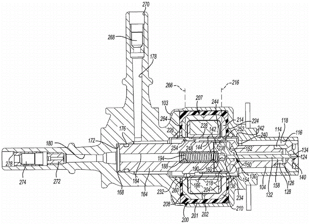
Referring now to fig. 2-4, the reagent injector 100 will be further described. Reagent injector 100 includes an outer injector body 102 having an outer body upper section 102a and an outer body lower section 102 b. The outer body lower segment 102b can include a deformable portion 103 that is crimped to the outer body upper segment 102 a. The elongated inner lower body 104 may be received within at least one of the outer body upper section 102a and the outer body lower section 102 b. The elongated inner lower body 104 defines a cylindrical central bore 106 in fluid communication with an orifice plate 108 to define at least one outlet aperture 110 completely through the orifice plate 108.
The valve member 130 is slidably mounted within the central bore 106. The valve member 130 includes an elongated pin 132 having a first end 134 that is conically shaped and an opposite second end 136. Tapered end 134 is selectively engageable with valve seat 140 to define a sealed and closed position when valve member 130 is seated. When the pin 132 unseats from the valve seat 140, an unsealed open position exists. The valve seat 140 surrounds the outlet orifice 110. As shown, the valve seat may be tapered or conical in shape to complement the shape of the tapered end 134 of the pin 132 to restrict the flow of reagent through the orifice 110. Depending on the application and operating environment, the pin 132 and orifice plate 108 may be made of a cemented carbide material that may provide desired performance characteristics and may be easier and more cost-effective to manufacture. Furthermore, limitations or disadvantages associated with other materials, such as limitations or disadvantages associated with manufacturing complex part shapes, may be avoided. Cemented carbides may provide additional advantages over carbon steels and tool steels where de-tempering (distemper) may occur, such as insensitivity to brazing temperatures in the range of 870 ℃ to 980 ℃. Cemented carbides can also provide a high surface hardness compared to the hardness achievable with most other steels. Cemented carbides may also have advantages in terms of overall wear resistance.
The pin head 142 is secured to the end 136 of the pin shaft 132. The pintle head 142 is slidably positioned within an enlarged bore 144 of the inner lower body 104. The sliding engagement at the run stage between the pin head 142 and the bore 144 provides upper guidance for the valve member 130. A lower valve member guide is formed at the sliding interface between the central bore 124 and the pin 132. Based on this arrangement, the valve member 130 is precisely aligned with the valve seat 140 and the outlet aperture 110.
The bottom surface 150 of the pin head 142 is spaced from the surface 152 of the inner lower body 104 to define a cavity 154 in fluid communication with the cavity 126 via a passage 158 defined as the portion of the central bore 106 not occupied by the pin shaft 132. The passage 160 extends through the pintle head 142 to define a portion of the reagent return passage.
A pole piece 164 having a first end 166 is sized to be received within the bore 144. The first end 166 of the pole piece 164 is secured to the inner lower body 104 using, for example, an electron beam welding process. The opposite second end 168 of the pole piece 164 sealingly fits within a bore 172 formed in the outer body upper section 102 a. The seal 176 separates an inlet passage 178 from an outlet passage 180 in the outer body upper section 102 a. The elongated pole piece 164 includes a central bore 184 extending therethrough. The central bore 184 is coaxially aligned with the central bore 106. A counterbore 188 extends inwardly from the second end 168 of the pole piece 164 and is coaxially aligned with a counterbore 190 extending to the pintle head 142. A compression spring 194 is positioned within counterbores 188, 190 to urge valve member 130 into engagement with seat 140.
As depicted in the figures, the electromagnet assembly 200 is positioned within the outer body upper section 102 a. The electromagnet assembly 200 may include a plastic material 201 that is overmolded to encapsulate the other components of the electromagnet assembly 200 therein. The electromagnet assembly 200 includes a wire coil 202 wound on a bobbin 204. The two-piece flux frame 207 includes a first frame half 208 secured to a second flux frame half 210 positioned to circumferentially surround the wire 202 and the bobbin 204. The pintle head 142 is constructed of a magnetic material (e.g., 430 stainless steel) such that energization of the coil 202 generates a magnetic field that urges the pintle head 142 toward the pole piece 164. The end 134 of the pin 132 disengages from the seat 140 to allow reagent to flow through the outlet aperture 110. For example, in response to a signal from the electronic injection controller 14, the coil 202 may be energized via the contact receptacle 211. The electronic injection controller 14 receives sensor input signals and determines when to inject a reagent into the exhaust stream to provide selective catalytic reduction of NOx emissions.
The controller 14 also defines a reagent injection duration and a reagent injection rate. Depending on engine operating conditions, load, ambient air temperature, exhaust temperature, and other factors, it may be desirable to control injector 100 to deliver a relatively wide range of reagent injection rates. To achieve this goal, it may be desirable to minimize the total time associated with moving the pin 132 from the seated position to the open position and back to the seated position. Precise control of the position of the pin head 142 can be achieved by providing a well defined magnetic circuit.
The flux frame half 210 includes a radially extending portion 214 that extends generally along a transverse line 216. The pintle head 142 includes an increased diameter portion 218 that intersects the line 216. Both flux frame half 210 and pin head 142 are made of magnetic material. To further define the magnetic circuit, the inner lower body 104 is constructed of a non-magnetic material (e.g., 304 stainless steel). The portion of the inner lower body 104 through which the wire 216 passes includes a minimum cross-sectional thickness to minimize any disruption of the magnetic flux.
The fluid sleeve assembly 220 is depicted as a three-piece assembly having a first flux bridge collar 224 and a second flux bridge collar 226 interconnected by a flux interrupter 228 in some embodiments, or a flux bridge 228' in some embodiments. The fluid sleeve assembly 220 is shaped as an elongated hollow cylindrical member sized and positioned to define a portion of the inlet passage 178. The first and second seals 232, 234 ensure that the pressurized reagent continues to travel through the inlet passage 178 but does not enter the electromagnet assembly 200. Each of the flux bridge collars 226 and 224 are substantially identical and include a counterbore having a first inner cylindrical surface 238 having a reduced first inner diameter and a second inner cylindrical surface 240 defining a larger second inner diameter. The outer surface of each flux collar is also stepped, including a cylindrical surface 242 having an outer diameter greater than the outer diameter of a second cylindrical surface 244. The flux break or bridge 228 is a substantially straight cylinder having an inner surface 248 engaged with and secured to each reduced diameter outer surface 244. The outer surface 242 is engaged with, or very closely spaced from, the walls 252 and 254 that define the circular apertures extending through the flux frame halves 210, 208. The first inner cylindrical surface 238 of the flux bridge collar 224 is sized to closely fit the inner lower body 104 and minimize any air gap through which the wire 216 passes.
The first inner cylindrical surface 238 of the flux bridge collar 226 is sized to interfit with the enlarged diameter portion 260 of the pole piece 164. The flux frame half 208 includes a radially inwardly extending portion 264 that extends along a line 266. The enlarged diameter portion 260 and the flux bridge collar 226 are axially positioned in alignment with the line 266 and provide a magnetic circuit path across the injector 100. Flux frame halves 208 and 210 are constructed of a magnetic material such as 1018 low carbon steel. The flux bridge collars 224 and 226 are constructed of ferritic 430 stainless steel. The pole piece 164 is made of ferritic 430 stainless steel or similar magnetic material. The pintle head 142 may be made from ferritic 430 stainless steel. In some embodiments, the flux interrupt 228 is made of non-ferritic and non-magnetic 304 stainless steel, as is the inner lower body 104. Constructing the previously described components from magnetic and non-magnetic materials, and positioning the magnetic materials adjacent to each other along lines 216 and 266 greatly improves the magnetic circuit performance associated with the electromagnet assembly 200. Benefits may include: the use of smaller coil wires, fewer turns of wire, and reduced amount of current provides an improved electromagnetic actuator having lower cost, reduced size and mass. Enhanced control over the position of the valve member 130 is also achieved. It should also be understood that the transverse plane defined by the ends of the cylindrical wire coil 202 and the plane containing the wires 216 and 266 may be interpreted as part of the magnetic circuit. At least one of these transverse planes passes through the pintle head 142, the flux bridge collars 224, 226, and the enlarged diameter pole shoe portion 260.
In some embodiments, the flux bridge 228' is made of a magnetic material (such as ferrite 430 stainless steel). In this embodiment, the flux bridge 228' is magnetic similar to the flux bridge collars 224, 226. As illustrated in fig. 5, constructing the previously described components from magnetic and non-magnetic materials, and positioning the magnetic materials adjacent to each other along lines 216 and 266, greatly improves the magnetic circuit performance associated with the electromagnet assembly 200. Benefits may include: the use of smaller coil wires, fewer turns of wire, and reduced amount of current provides an improved electromagnetic actuator having lower cost, reduced size and mass. Enhanced control over the position of the valve member 130 is also achieved. It should also be understood that the transverse plane defined by the ends of the cylindrical wire coil 202 and the plane containing the wires 216 and 266 may be interpreted as part of the magnetic circuit. At least one of these transverse planes passes through the pintle head 142, the flux bridge collars 224, 226, the flux bridge 228', and the enlarged diameter pole piece portion 260.
As illustrated in fig. 5, in some embodiments, the flux bridge collars 224, 226 and the flux bridge 228' may be a single, unitary member. In this manner, the flux bridge collars 224, 226 and the flux bridge 228' constitute portions or regions of a continuous member. In some embodiments, the flux bridge collars 224, 226 and the flux bridge 228' may include a plurality of discrete members that are similarly constructed and oriented as the flux bridge collars 224, 226 and the flux break 228. Embodiments employing flux bridges 228 'extending between the flux bridge collars 224 may define enhanced and/or increased flux densities extending along the flux bridges 228'. To further enhance and/or increase flux density, in some embodiments, the length of the enlarged bore 144 of the inner lower body 104 may be shortened, as illustrated in fig. 5 in comparison to fig. 4.
When pin 132 is in the closed position, a reagent fluid path is defined within injector 100. The fluid path provides for circulation of fluid through the injector 100. More specifically, the reagent fluid path extends from inlet 270 of outer body upper section 102a, through inlet filter 268, and inlet passage 178 (including the gap between the outer surface of pole piece 164 and outer body upper section 102a), through the path formed in fluid sleeve assembly 220, fluid passage 118, plate holder 112 through cavity 126, passage 158, passage 160, central bore 184, outlet passage 180, orifice 272, outlet filter 274, to exit outlet 278. Typically, the reagent entering the inlet 270 is at a first, relatively low temperature compared to the exhaust gas passing through the exhaust system 18 immediately adjacent the orifice 110. The recirculation of reagent through injector 100 transfers heat from orifice plate 108 and orifice plate holder 112. Reagent recirculation also helps to transfer heat from the coil 202 because the bobbin 204 is placed in intimate contact with the fluid sleeve assembly 220 through which the reagent flows.
When the coil 202 is energized, a magnetic field is generated and the pin head 142 is urged against the biasing force of the spring 194, unseating the pin end 134. The pressurized reagent located within cavity 126 passes between pin 132 and seat 140 and through exit orifice 110 to inject the reagent into the exhaust flow flowing through exhaust system 18. The electromagnet assembly 200 may be controlled by any number of methods including pulse width modulation to open and close the exit orifice 110 at a predetermined frequency.
In an alternative embodiment depicted in fig. 6-9, the injector 300 is configured substantially similar to the injector 100 previously defined. To avoid repetition, only the differences in the embodiments will be described in detail. It should be understood that the description of similar components shown in fig. 1-5 applies to injector 300.
The eductor 300 includes a cage filter 302 that may additionally or alternatively be provided to one or both of the inlet filter 268 and the outlet filter 274. Cage filter 302 includes a porous filter 304 secured to a cage 306. Filter 304 is a substantially hollow cylindrical member configured to allow injected urea to flow freely therethrough, but to restrict contaminants from further flowing through injector 300. Cage 306 includes a substantially cylindrical hollow body 308 having a first end 310 and an opposite second end 312. The cage 306 includes an end wall 316 positioned at the first end 310. An aperture 318 extends through end wall 316. End wall 316 includes an integrally formed first lip seal 320 as depicted in fig. 8. When viewed in cross-section, the thickness of end wall 316 decreases from an outer cylindrical surface 322 to an inner circumferential surface 324 that defines the orifice 318. First lip seal 320 is configured to flex and/or slightly plastically and/or elastically deform when assembled to pole piece 164 'to sealingly engage outer cylindrical surface 328 of pole piece 164' with an interference fit.
The flange 330 includes a seat 342 positioned to engage the fluid sleeve assembly 220'. The fluid sleeve assembly 220' is constructed substantially similar to the fluid sleeve assembly 220, which is a three-piece assembly having flux bridge collars 224' and 226' on opposite ends constructed of ferrite 430 stainless steel or similar ferrite material. The flux bridge collars 224' and 226' are interconnected by a flux interrupt 228 "in some embodiments and a flux bridge 228 '" in other embodiments. The flux interrupter 228 "is constructed of a non-ferritic and non-magnetic 304 stainless steel or similar material. The flux bridge 228 "' is similarly configured as flux bridge collars 224', 226 '.
The flux bridge collar 224' includes a first radially extending flange 346 and a second radially extending flange 348, respectively. The first flange 346 engages the seat 342 of the cage filter 302. The first flange 346 is axially offset relative to the end of the first flux bridge collar 224 'such that the axially extending portion 350 of the first flux bridge collar 224' serves to guide and align the cage 306.
It is contemplated that the cage 306 is constructed of nylon 6,6 with 30% glass reinforcement. The mesh may be constructed of metal or plastic. In the present example, the mesh 304 is comprised of nylon 6, with apertures extending therethrough and sized about 40 microns. Body 308 includes a plurality of windows 364 extending therethrough. Each window is covered by a portion of the mesh 304. In order for fluid to pass through the cage filter 302, the fluid must pass through the mesh 304.
Moreover, the foregoing discussion discloses and describes merely exemplary embodiments of the present disclosure. One skilled in the art will readily recognize from such discussion, and from the accompanying drawings and claims, that various changes, modifications and variations can be made therein without departing from the spirit and scope of the disclosure as defined in the following claims.
Claims (20)
1. An injector for injecting a reagent, the injector comprising:
a housing;
an axially translatable valve member positioned within the housing;
an electromagnet positioned within the housing and comprising a wire coil surrounding at least a portion of the axially translatable valve member, wherein the axially translatable valve member moves between a seated position and an unseated position in response to the electromagnet being energized;
a flux frame surrounding the wire coil, the flux frame including a first radially extending portion and a second radially extending portion, the first and second radially extending portions being axially spaced from each other and extending along parallel planes positioned on opposite sides of the wire coil;
a flux sleeve comprising two magnetic flux bridge collar portions interconnected by one of a magnetic flux bridge portion and a non-magnetic flux interruption portion, each of the two magnetic flux bridge collar portions intersecting one of first and second planes in which the first and second radially extending flux frame portions lie, the one of a flux bridge portion and a flux interruption portion being surrounded by the wire coil and positioned axially between the parallel planes;
a tubular pole piece disposed within the housing, wherein the tubular pole piece defines a return passage for reagent flow when the axially translatable valve member is in at least one of the seated position and the unseated position; and
a filter positioned within the housing and surrounding the tubular pole piece, the filter comprising a cage and a mesh secured to the cage, the mesh covering a window extending through the cage, the cage having a deformable first seal biasedly engaging an outer surface of the tubular pole piece, the cage comprising a second seal biasedly engaging the housing, the deformable first seal and the second seal defining an enclosed volume between the housing and the filter such that all reagent flowing through the injector passes through the mesh.
2. The injector of claim 1, wherein the first deformable seal and the second seal are integrally formed with the cage, wherein the cage, the first deformable seal and the second seal define a one-piece structure.
3. The injector of claim 2, wherein the cage is overmolded onto the mesh.
4. The injector of claim 1, wherein the deformable first seal extends radially inward from the web and the second seal extends radially outward from the web.
5. The sprayer of claim 1 wherein the mesh is shaped as a hollow upright cylinder.
6. The injector of claim 1, wherein the cage comprises a cup-shaped structure having the deformable first seal positioned at an opposite end relative to the second seal.
7. The injector of claim 1 wherein the cage is constructed of a nylon 6,6 material.
8. The injector of claim 1, wherein the deformable first seal and the second seal are deformable lip seals.
9. The injector of claim 1, wherein the second seal is shaped as a radially outwardly extending flange forming a 45 degree angle with a longitudinal axis of the injector.
10. The injector of claim 1, wherein the tubular pole piece extends through the entire filter and beyond the axial extent of the filter in each direction.
11. The injector of claim 1 wherein the flux sleeve comprises three coaxially aligned tubes connected to each other.
12. The injector of claim 1, wherein the flux sleeve is a continuous member including the two magnetic flux bridge collar portions and one of the magnetic flux bridge portion and a non-magnetic flux interruption portion.
13. The injector of claim 1 wherein the reagent is directed to flow through the flux sleeve.
14. The injector of claim 1, wherein the tubular valve member includes a cylindrical pin coupled to an enlarged pin head made of a magnetic material and positioned such that one of the planes intersects the enlarged pin head when the tubular valve member is in the seated position.
15. The injector of claim 1, wherein the tubular pole piece forms an interference fit with the deformable first seal, the second seal, and the housing, the housing defining another interference fit.
16. The injector of claim 1, wherein the tubular pole piece is positioned axially within the wire loop.
17. An injector for injecting a reagent, the injector comprising:
a housing;
an axially translatable valve member positioned within the housing;
a pole piece disposed within the housing;
an electromagnet positioned within the housing and comprising a cylindrical wire coil, wherein the axially translatable valve member moves between a seated position and an unseated position in response to energization of the electromagnet;
a flux sleeve passing through the cylindrical wire coil and comprising two magnetic portions interconnected by one of a magnetic flux bridge portion and a non-magnetic flux interruption portion, each of the magnetic portions aligned with a transverse plane defined by an end of the cylindrical wire coil, wherein a reagent flow path extends between the flux sleeve and the pole piece; and
a filter positioned within the housing and surrounding the pole piece, the filter including a cage and a mesh secured to the cage, the mesh covering a window extending through the cage, the cage having a deformable first seal biasedly engaging an outer surface of the pole piece, the cage including a second seal biasedly engaging the housing, the cage further including a seat engaging the flux sleeve, the deformable first seal and the second seal defining an enclosed volume between the housing and the filter such that all reagent flowing through the injector passes through the mesh.
18. The injector of claim 17, wherein the first deformable seal and the second seal are integrally formed with the cage, wherein the cage, the first deformable seal and the second seal define a one-piece structure.
19. The injector of claim 17, wherein the deformable first seal extends radially inward from the web and the second seal extends radially outward from the web.
20. The injector of claim 17, wherein the deformable first seal and the second seal are deformable lip seals.
Applications Claiming Priority (3)
Application Number | Priority Date | Filing Date | Title |
---|---|---|---|
US16/106,891 US10704444B2 (en) | 2018-08-21 | 2018-08-21 | Injector fluid filter with upper and lower lip seal |
US16/106,891 | 2018-08-21 | ||
PCT/US2019/043580 WO2020040931A1 (en) | 2018-08-21 | 2019-07-26 | Injector fluid filter with upper and lower lip seal |
Publications (2)
Publication Number | Publication Date |
---|---|
CN112469891A CN112469891A (en) | 2021-03-09 |
CN112469891B true CN112469891B (en) | 2022-05-10 |
Family
ID=69584415
Family Applications (1)
Application Number | Title | Priority Date | Filing Date |
---|---|---|---|
CN201980048955.5A Active CN112469891B (en) | 2018-08-21 | 2019-07-26 | Injector fluid filter with upper and lower lip seals |
Country Status (4)
Country | Link |
---|---|
US (1) | US10704444B2 (en) |
CN (1) | CN112469891B (en) |
DE (1) | DE112019003169T5 (en) |
WO (1) | WO2020040931A1 (en) |
Citations (6)
Publication number | Priority date | Publication date | Assignee | Title |
---|---|---|---|---|
EP2933472A1 (en) * | 2014-04-16 | 2015-10-21 | Continental Automotive GmbH | Fuel injection valve for an internal combustion engine |
CN106285854A (en) * | 2015-05-07 | 2017-01-04 | 浙江福爱电子有限公司 | A kind of SCR liquid injection apparatus |
DE102016003140A1 (en) * | 2016-03-15 | 2017-09-21 | Rüdiger Ufermann | "Arrangement for reducing particulate emissions from internal combustion engines" |
CN206600224U (en) * | 2017-02-24 | 2017-10-31 | 中国第一汽车股份有限公司 | A kind of swirling flow ejector |
CN206668368U (en) * | 2016-04-14 | 2017-11-24 | 天纳克(苏州)排放系统有限公司 | Integrating device and exhaust gas aftertreatment system |
DE102016225946A1 (en) * | 2016-12-22 | 2018-06-28 | Robert Bosch Gmbh | Fuel injector and its use |
Family Cites Families (121)
Publication number | Priority date | Publication date | Assignee | Title |
---|---|---|---|---|
US702770A (en) | 1902-01-25 | 1902-06-17 | Thomas Collinsworth Bornman | Nut-lock. |
US2235834A (en) | 1939-06-01 | 1941-03-25 | Claude S Gillette | Fuel oil burner nozzle |
US2637344A (en) | 1949-08-22 | 1953-05-05 | Milwaukee Gas Specialty Co | Electroinductively actuated valve |
GB702770A (en) | 1951-04-16 | 1954-01-20 | Lucas Industries Ltd | Liquid fuel injection nozzles |
US3771819A (en) | 1971-12-01 | 1973-11-13 | Hydrasearch Co Inc | Axially and rotatably movable flange connector |
US3927984A (en) | 1973-12-07 | 1975-12-23 | Gen Motors Corp | Catalytic converter bed support means |
DE2460111A1 (en) | 1974-04-13 | 1976-07-15 | Daimler Benz Ag | INJECTION VALVE |
DE2418227C3 (en) | 1974-04-13 | 1978-09-14 | Daimler-Benz Ag, 7000 Stuttgart | Low-pressure injection valve for introducing liquid fuel into the combustion chamber of an internal combustion engine |
DE2720144A1 (en) | 1977-05-05 | 1978-11-16 | Volkswagenwerk Ag | INJECTION DEVICE, IN PARTICULAR FOR A COMBUSTION ENGINE |
DE2725135C2 (en) | 1977-06-03 | 1987-01-15 | Robert Bosch Gmbh, 7000 Stuttgart | Electromagnetic fuel injection valve for internal combustion engines |
JPS6042351B2 (en) | 1978-11-07 | 1985-09-21 | 株式会社豊田中央研究所 | Reflux type volute injection valve |
DE3010612A1 (en) | 1980-03-20 | 1981-10-01 | Robert Bosch Gmbh, 7000 Stuttgart | ELECTROMAGNETICALLY ACTUABLE VALVE |
JPS633410Y2 (en) | 1981-06-22 | 1988-01-27 | ||
US4499878A (en) | 1982-10-25 | 1985-02-19 | Nippon Soken, Inc. | Fuel injection system for an internal combustion engine |
JPH0650091B2 (en) | 1983-08-12 | 1994-06-29 | 株式会社日本自動車部品総合研究所 | Fuel injection control method for a burning engine |
JPS60119364A (en) | 1983-12-02 | 1985-06-26 | Hitachi Ltd | electromagnetic fuel injection valve |
DE3502410A1 (en) | 1985-01-25 | 1986-07-31 | Robert Bosch Gmbh, 7000 Stuttgart | ELECTROMAGNETICALLY ACTUABLE FUEL INJECTION VALVE |
US4610080A (en) | 1985-07-29 | 1986-09-09 | Allied Corporation | Method for controlling fuel injector lift |
US4742964A (en) | 1985-10-30 | 1988-05-10 | Aisan Kogyo Kabushiki Kaisha | Electromagnetic fuel injector |
WO1988003225A1 (en) | 1986-10-30 | 1988-05-05 | Allied Corporation | High pressure vortex injector |
US4805837A (en) | 1986-10-30 | 1989-02-21 | Allied Corporation | Injector with swirl chamber return |
DE3878599T2 (en) | 1987-06-26 | 1993-09-23 | Hitachi Automotive Eng | ELECTROMAGNETIC FUEL INJECTION VALVE. |
DE3809292C2 (en) | 1988-03-19 | 1997-02-06 | Messer Griesheim Gmbh | Liquid jet cutting torch |
US5114116A (en) | 1989-12-07 | 1992-05-19 | Feinmechanische Werke Mainz Gmbh | Electromagnetically actuated quick-action switching valve |
JPH0510221A (en) | 1991-07-03 | 1993-01-19 | Nippondenso Co Ltd | Solenoid fuel injection valve |
JPH05141330A (en) | 1991-11-15 | 1993-06-08 | Nippon Soken Inc | Fuel injection device |
US5307997A (en) | 1993-03-12 | 1994-05-03 | Siemens Automotive L.P. | Fuel injector swirl passages |
US5325838A (en) | 1993-05-28 | 1994-07-05 | Bennett David E | Liquified petroleum gas fuel injector |
US5522218A (en) | 1994-08-23 | 1996-06-04 | Caterpillar Inc. | Combustion exhaust purification system and method |
US5570841A (en) | 1994-10-07 | 1996-11-05 | Siemens Automotive Corporation | Multiple disk swirl atomizer for fuel injector |
DE4436397B4 (en) | 1994-10-12 | 2006-06-08 | Robert Bosch Gmbh | Device for aftertreatment of exhaust gases |
US5571248A (en) | 1995-03-10 | 1996-11-05 | General Motors Corporation | Pressure regulator |
US5943858A (en) | 1995-05-19 | 1999-08-31 | Siemens Aktiengesellschaft | Premixing chamber for an exhaust gas purification system |
US5979866A (en) | 1995-06-06 | 1999-11-09 | Sagem, Inc. | Electromagnetically actuated disc-type valve |
JPH0950491A (en) | 1995-08-10 | 1997-02-18 | Nippon Telegr & Teleph Corp <Ntt> | Method for recognizing handwritten character on-line and device therefor |
US5687698A (en) | 1996-08-29 | 1997-11-18 | General Motors Corporation | Exhaust gas recirculation valve |
JPH11132127A (en) | 1996-11-13 | 1999-05-18 | Denso Corp | Fuel injection valve and assembling method thereof |
US5713327A (en) | 1997-01-03 | 1998-02-03 | Tilton; Charles L. | Liquid fuel injection device with pressure-swirl atomizers |
JPH10220319A (en) | 1997-02-06 | 1998-08-18 | Denso Corp | Fuel injection valve |
US6063350A (en) | 1997-04-02 | 2000-05-16 | Clean Diesel Technologies, Inc. | Reducing nox emissions from an engine by temperature-controlled urea injection for selective catalytic reduction |
US5976475A (en) | 1997-04-02 | 1999-11-02 | Clean Diesel Technologies, Inc. | Reducing NOx emissions from an engine by temperature-controlled urea injection for selective catalytic reduction |
US5924280A (en) | 1997-04-04 | 1999-07-20 | Clean Diesel Technologies, Inc. | Reducing NOx emissions from an engine while maximizing fuel economy |
DE19726392A1 (en) | 1997-06-21 | 1998-12-24 | Bosch Gmbh Robert | Mixture dispenser |
US5884611A (en) | 1997-10-14 | 1999-03-23 | Cummins Engine Company, Inc. | Effervescent injector for diesel engines |
US5857478A (en) | 1997-10-28 | 1999-01-12 | General Motors Corporation | Demand responsive flow control valve |
JPH11166410A (en) | 1997-12-04 | 1999-06-22 | Hino Motors Ltd | Exhaust emission control device |
DE19806265C5 (en) | 1998-02-16 | 2004-07-22 | Siemens Ag | dosing |
US6206343B1 (en) | 1998-05-27 | 2001-03-27 | Aisin Seiki Kabushiki Kaisha | Solenoid valve |
US6279603B1 (en) | 1998-10-01 | 2001-08-28 | Ambac International | Fluid-cooled injector |
US6273120B1 (en) | 1998-11-12 | 2001-08-14 | Siemens Aktiengesellschaft | Device for introducing a liquid reducing agent into an exhaust gas purification system |
DE19855244C2 (en) | 1998-11-30 | 2000-09-21 | Freudenberg Carl Fa | Filter element |
DE19856366C1 (en) | 1998-12-07 | 2000-04-20 | Siemens Ag | Urea injection system treating exhaust gases from lean burn engine, comprises air-cooling jacket surrounding injector valve to keep it cool, so that a petrol injection valve may be used |
US5970953A (en) | 1999-01-12 | 1999-10-26 | Siemens Automotive Corporation | High pressure injector clip |
US6164322A (en) | 1999-01-15 | 2000-12-26 | Saturn Electronic & Engineering, Inc. | Pressure relief latching solenoid valve |
DE19901915C1 (en) | 1999-01-19 | 2000-04-20 | Siemens Ag | Catalytic conversion of nitrogen oxides in exhaust gases using urea reductant is controlled by time differentiation of engine operational parameter, adjusting reductant excess more swiftly as a function of the result |
DE19907897A1 (en) | 1999-02-24 | 2000-08-31 | Bosch Gmbh Robert | Fuel injector |
DE19907899A1 (en) | 1999-02-24 | 2000-08-31 | Bosch Gmbh Robert | Fuel injector |
US6409102B1 (en) | 1999-03-15 | 2002-06-25 | Aerosance, Inc. | Fuel injector assembly |
JP4067237B2 (en) | 1999-05-27 | 2008-03-26 | ヤマハマリン株式会社 | In-cylinder injection engine |
US6168098B1 (en) | 1999-06-09 | 2001-01-02 | Siemens Automotive Corporation | Fuel injector with tubular lower needle guide |
US6293097B1 (en) | 1999-08-16 | 2001-09-25 | Ford Global Technologies, Inc. | On-board reductant delivery system |
US6257496B1 (en) | 1999-12-23 | 2001-07-10 | Siemens Automotive Corporation | Fuel injector having an integrated seat and swirl generator |
US6454192B2 (en) | 2000-01-19 | 2002-09-24 | Delphi Technologies, Inc. | Engine fuel injector with assembled magnetic coil body |
JP2001342928A (en) | 2000-05-30 | 2001-12-14 | Hitachi Ltd | Electromagnetic fuel injection device |
US6526746B1 (en) | 2000-08-02 | 2003-03-04 | Ford Global Technologies, Inc. | On-board reductant delivery assembly |
DE10049518B4 (en) | 2000-10-06 | 2005-11-24 | Robert Bosch Gmbh | Fuel injector |
US6415602B1 (en) | 2000-10-16 | 2002-07-09 | Engelhard Corporation | Control system for mobile NOx SCR applications |
US20040041112A1 (en) * | 2000-10-30 | 2004-03-04 | Goossens Andre F.L. | Electromagnetic valve and method for operating an electromagnetic valve |
JP3745232B2 (en) | 2001-01-17 | 2006-02-15 | 愛三工業株式会社 | Fluid injection nozzle and fluid injection valve including the fluid injection nozzle |
DE10103933A1 (en) | 2001-01-30 | 2002-08-14 | Bosch Gmbh Robert | Fuel injector |
DE10116214A1 (en) | 2001-03-30 | 2002-10-10 | Bosch Gmbh Robert | Device for the aftertreatment of exhaust gases from an internal combustion engine |
JP3888518B2 (en) | 2001-09-10 | 2007-03-07 | 株式会社デンソー | Exhaust purification device |
JP4720054B2 (en) | 2001-09-11 | 2011-07-13 | トヨタ自動車株式会社 | Exhaust gas purification device for internal combustion engine |
JP3888519B2 (en) | 2001-09-12 | 2007-03-07 | 株式会社デンソー | Exhaust purification device |
DE10159003A1 (en) | 2001-11-30 | 2003-06-18 | Bosch Gmbh Robert | Injector with a solenoid valve for controlling an injection valve |
CA2405350C (en) | 2002-09-26 | 2004-08-10 | S. Michael Baker | Liquid cooled fuel injection valve and method of operating a liquid cooled fuel injection valve |
WO2004030827A1 (en) | 2002-10-02 | 2004-04-15 | Spraying Systems Co. | Lance-type liquid reducing agent spray device |
BR0316367A (en) | 2002-11-15 | 2005-10-04 | Catalytica Energy Sys Inc | Devices and Methods for Reducing Poison-Burning Engine Nox Emissions |
JP3994438B2 (en) | 2002-11-26 | 2007-10-17 | 株式会社デンソー | Fluid ejecting apparatus and manufacturing method thereof |
US6922987B2 (en) | 2003-02-12 | 2005-08-02 | Fleetguard, Inc. | System and method for enhancing internal combustion engine aftertreatment applications by superheated fuel injection |
US7021558B2 (en) | 2003-04-25 | 2006-04-04 | Cummins Inc. | Fuel injector having a cooled lower nozzle body |
US7237731B2 (en) | 2003-08-19 | 2007-07-03 | Siemens Vdo Automotive Corporation | Fuel injector with a deep pocket seat and method of maintaining spatial orientation |
US7299997B2 (en) | 2003-10-27 | 2007-11-27 | Siemens Vdo Automotive Corporation | Fuel injector with sauter-mean-diameter atomization spray of less than 70 microns |
JP2005201158A (en) | 2004-01-16 | 2005-07-28 | Hino Motors Ltd | System of adding fuel to exhaust pipe of diesel engine |
US7467749B2 (en) | 2004-04-26 | 2008-12-23 | Tenneco Automotive Operating Company Inc. | Methods and apparatus for injecting atomized reagent |
US8047452B2 (en) | 2004-04-26 | 2011-11-01 | Tenneco Automotive Operating Company Inc. | Method and apparatus for injecting atomized fluids |
DE102004022115A1 (en) | 2004-05-05 | 2005-11-24 | Robert Bosch Gmbh | Method for introducing a reagent into an exhaust duct of an internal combustion engine and device for carrying out the method |
JP3993594B2 (en) | 2004-09-27 | 2007-10-17 | 株式会社ケーヒン | Electromagnetic fuel injection valve |
EP1795739B1 (en) | 2004-09-27 | 2012-12-26 | Keihin Corporation | Solenoid fuel injection valve |
US7414502B2 (en) | 2005-02-14 | 2008-08-19 | Delta Power Company | Harsh environment coil-actuator for a cartridge type valve |
JP2006226162A (en) | 2005-02-16 | 2006-08-31 | Hitachi Ltd | Exhaust pipe injection valve |
US7469906B2 (en) | 2005-07-01 | 2008-12-30 | Spx Corporation | Filter lip seal and method |
DE102005035347B3 (en) | 2005-07-28 | 2006-08-10 | L'orange Gmbh | Fuel injector for an internal combustion engine has an axial hole for fuel in a nozzle/jet unit with an injector needle sliding on-axis in the nozzle/jet unit |
US7832735B2 (en) | 2006-01-11 | 2010-11-16 | Skf Usa Inc. | Seal assembly with protective filter |
SE529591C2 (en) | 2006-02-08 | 2007-09-25 | Stt Emtec Ab | injection device |
WO2007142899A2 (en) | 2006-05-31 | 2007-12-13 | Tenneco Automotive Operating Company Inc. | Method and apparatus for reducing emissions in diesel engines |
US7497077B2 (en) | 2006-07-26 | 2009-03-03 | Southwest Research Institute | System and method for dispensing an aqueous urea solution into an exhaust gas stream |
JP4730278B2 (en) | 2006-10-20 | 2011-07-20 | 株式会社デンソー | Engine exhaust purification system |
DE102006061730A1 (en) | 2006-12-28 | 2008-07-03 | Robert Bosch Gmbh | Selective catalytic reduction injection device for use in internal combustion engine, has sleeve including elongated thin-walled connecting section connected indirectly and positively to axial end by flange |
DE102007005434A1 (en) | 2007-01-30 | 2008-07-31 | Svm Schultz Verwaltungs-Gmbh & Co. Kg | Double acting electromagnetic actuator for hydraulic and pneumatic applications, has anchor arranged in coil with two permanent magnets in axial direction and anchor is supported in pole tube arranged in coil |
US7503543B2 (en) | 2007-02-06 | 2009-03-17 | Kabushiki Kaisha Kawasaki Precision Machinery | Guide body, manufacturing method thereof, and electromagnetic valve device |
EP2538049B1 (en) | 2007-03-30 | 2015-03-18 | Continental Automotive Systems US, Inc. | Reductant delivery unit for selective catalytic reduction |
DE102008008761A1 (en) | 2008-02-12 | 2009-08-13 | Robert Bosch Gmbh | actuating magnet |
KR100962779B1 (en) | 2008-03-03 | 2010-06-09 | 현대자동차주식회사 | Injector device for reducing vehicle exhaust gas |
GB2460825A (en) | 2008-06-06 | 2009-12-16 | Delphi Tech Inc | Reagent dosing system |
JP5223570B2 (en) | 2008-09-29 | 2013-06-26 | セイコーエプソン株式会社 | Manufacturing method of composite sintered body, composite sintered body, and fuel injection valve |
US8564924B1 (en) * | 2008-10-14 | 2013-10-22 | Global Plasma Solutions, Llc | Systems and methods of air treatment using bipolar ionization |
BRPI1007301A2 (en) | 2009-02-02 | 2016-02-10 | Tenneco Automotive Operating | injector mounting system |
EP2336544A1 (en) | 2009-12-14 | 2011-06-22 | Delphi Technologies, Inc. | Anti-bounce mechanism for fuel injectors |
US8740113B2 (en) | 2010-02-10 | 2014-06-03 | Tenneco Automotive Operating Company, Inc. | Pressure swirl flow injector with reduced flow variability and return flow |
US8973895B2 (en) * | 2010-02-10 | 2015-03-10 | Tenneco Automotive Operating Company Inc. | Electromagnetically controlled injector having flux bridge and flux break |
US9683472B2 (en) * | 2010-02-10 | 2017-06-20 | Tenneco Automotive Operating Company Inc. | Electromagnetically controlled injector having flux bridge and flux break |
DE112011100504B4 (en) | 2010-02-10 | 2023-08-03 | Tenneco Automotive Operating Company Inc. | Pressurized swirl flow injector with reduced flow variability and reverse flow |
EP2500610B1 (en) | 2011-03-12 | 2016-11-30 | Asco Numatics GmbH | Device for regulating the flow of a fluid or gaseous medium |
EP2541010A1 (en) | 2011-06-28 | 2013-01-02 | Delphi Technologies Holding S.à.r.l. | Pump assembly |
DE102012206481A1 (en) | 2012-04-19 | 2013-10-24 | Robert Bosch Gmbh | metering |
US8978364B2 (en) * | 2012-05-07 | 2015-03-17 | Tenneco Automotive Operating Company Inc. | Reagent injector |
US8910884B2 (en) | 2012-05-10 | 2014-12-16 | Tenneco Automotive Operating Company Inc. | Coaxial flow injector |
DE102012221479A1 (en) | 2012-11-23 | 2014-05-28 | Robert Bosch Gmbh | Device, in particular pump-nozzle system |
US10539057B2 (en) * | 2017-09-14 | 2020-01-21 | Vitesco Technologies USA, LLC | Injector for reductant delivery unit having reduced fluid volume |
US10683786B2 (en) * | 2018-07-25 | 2020-06-16 | Tenneco Automotive Operating Company Inc. | Reagent injector |
-
2018
- 2018-08-21 US US16/106,891 patent/US10704444B2/en active Active
-
2019
- 2019-07-26 DE DE112019003169.4T patent/DE112019003169T5/en active Granted
- 2019-07-26 WO PCT/US2019/043580 patent/WO2020040931A1/en active Application Filing
- 2019-07-26 CN CN201980048955.5A patent/CN112469891B/en active Active
Patent Citations (6)
Publication number | Priority date | Publication date | Assignee | Title |
---|---|---|---|---|
EP2933472A1 (en) * | 2014-04-16 | 2015-10-21 | Continental Automotive GmbH | Fuel injection valve for an internal combustion engine |
CN106285854A (en) * | 2015-05-07 | 2017-01-04 | 浙江福爱电子有限公司 | A kind of SCR liquid injection apparatus |
DE102016003140A1 (en) * | 2016-03-15 | 2017-09-21 | Rüdiger Ufermann | "Arrangement for reducing particulate emissions from internal combustion engines" |
CN206668368U (en) * | 2016-04-14 | 2017-11-24 | 天纳克(苏州)排放系统有限公司 | Integrating device and exhaust gas aftertreatment system |
DE102016225946A1 (en) * | 2016-12-22 | 2018-06-28 | Robert Bosch Gmbh | Fuel injector and its use |
CN206600224U (en) * | 2017-02-24 | 2017-10-31 | 中国第一汽车股份有限公司 | A kind of swirling flow ejector |
Also Published As
Publication number | Publication date |
---|---|
CN112469891A (en) | 2021-03-09 |
US10704444B2 (en) | 2020-07-07 |
DE112019003169T5 (en) | 2021-04-29 |
WO2020040931A1 (en) | 2020-02-27 |
US20200063624A1 (en) | 2020-02-27 |
Similar Documents
Publication | Publication Date | Title |
---|---|---|
US8973895B2 (en) | Electromagnetically controlled injector having flux bridge and flux break | |
US9759113B2 (en) | Coaxial flow injector | |
US9683472B2 (en) | Electromagnetically controlled injector having flux bridge and flux break | |
US8978364B2 (en) | Reagent injector | |
JP6097746B2 (en) | Injector that injects reagent | |
US8998116B2 (en) | Reagent injector with crimped pintle | |
CN112512665B (en) | Reagent injector freeze protection | |
CN112513435B (en) | Reagent injector | |
CN112469891B (en) | Injector fluid filter with upper and lower lip seals | |
US11174773B2 (en) | Reagent injector |
Legal Events
Date | Code | Title | Description |
---|---|---|---|
PB01 | Publication | ||
SE01 | Entry into force of request for substantive examination | ||
GR01 | Patent grant | ||
GR01 | Patent grant |