[go: up one dir, main page]

CN112220505A - Flow regulating device in heart - Google Patents

Flow regulating device in heart Download PDF

Info

Publication number
CN112220505A
CN112220505A CN202011077936.6A CN202011077936A CN112220505A CN 112220505 A CN112220505 A CN 112220505A CN 202011077936 A CN202011077936 A CN 202011077936A CN 112220505 A CN112220505 A CN 112220505A
Authority
CN
China
Prior art keywords
proximal
distal
blood flow
flow regulator
regulator according
Prior art date
Legal status (The legal status is an assumption and is not a legal conclusion. Google has not performed a legal analysis and makes no representation as to the accuracy of the status listed.)
Pending
Application number
CN202011077936.6A
Other languages
Chinese (zh)
Inventor
约瑟夫·约翰·维图卡蒂尔
穆罕默德·哈坎·阿克珀纳尔
Current Assignee (The listed assignees may be inaccurate. Google has not performed a legal analysis and makes no representation or warranty as to the accuracy of the list.)
Occlutech GmbH
Original Assignee
Occlutech Holding AG
Priority date (The priority date is an assumption and is not a legal conclusion. Google has not performed a legal analysis and makes no representation as to the accuracy of the date listed.)
Filing date
Publication date
Family has litigation
First worldwide family litigation filed litigation Critical https://patents.darts-ip.com/?family=54062763&utm_source=google_patent&utm_medium=platform_link&utm_campaign=public_patent_search&patent=CN112220505(A) "Global patent litigation dataset” by Darts-ip is licensed under a Creative Commons Attribution 4.0 International License.
Application filed by Occlutech Holding AG filed Critical Occlutech Holding AG
Publication of CN112220505A publication Critical patent/CN112220505A/en
Pending legal-status Critical Current

Links

Images

Classifications

    • AHUMAN NECESSITIES
    • A61MEDICAL OR VETERINARY SCIENCE; HYGIENE
    • A61FFILTERS IMPLANTABLE INTO BLOOD VESSELS; PROSTHESES; DEVICES PROVIDING PATENCY TO, OR PREVENTING COLLAPSING OF, TUBULAR STRUCTURES OF THE BODY, e.g. STENTS; ORTHOPAEDIC, NURSING OR CONTRACEPTIVE DEVICES; FOMENTATION; TREATMENT OR PROTECTION OF EYES OR EARS; BANDAGES, DRESSINGS OR ABSORBENT PADS; FIRST-AID KITS
    • A61F2/00Filters implantable into blood vessels; Prostheses, i.e. artificial substitutes or replacements for parts of the body; Appliances for connecting them with the body; Devices providing patency to, or preventing collapsing of, tubular structures of the body, e.g. stents
    • A61F2/02Prostheses implantable into the body
    • A61F2/24Heart valves ; Vascular valves, e.g. venous valves; Heart implants, e.g. passive devices for improving the function of the native valve or the heart muscle; Transmyocardial revascularisation [TMR] devices; Valves implantable in the body
    • A61F2/2493Transmyocardial revascularisation [TMR] devices
    • AHUMAN NECESSITIES
    • A61MEDICAL OR VETERINARY SCIENCE; HYGIENE
    • A61BDIAGNOSIS; SURGERY; IDENTIFICATION
    • A61B17/00Surgical instruments, devices or methods
    • A61B17/0057Implements for plugging an opening in the wall of a hollow or tubular organ, e.g. for sealing a vessel puncture or closing a cardiac septal defect
    • AHUMAN NECESSITIES
    • A61MEDICAL OR VETERINARY SCIENCE; HYGIENE
    • A61BDIAGNOSIS; SURGERY; IDENTIFICATION
    • A61B17/00Surgical instruments, devices or methods
    • A61B17/12Surgical instruments, devices or methods for ligaturing or otherwise compressing tubular parts of the body, e.g. blood vessels or umbilical cord
    • A61B17/12022Occluding by internal devices, e.g. balloons or releasable wires
    • A61B17/12099Occluding by internal devices, e.g. balloons or releasable wires characterised by the location of the occluder
    • A61B17/12109Occluding by internal devices, e.g. balloons or releasable wires characterised by the location of the occluder in a blood vessel
    • AHUMAN NECESSITIES
    • A61MEDICAL OR VETERINARY SCIENCE; HYGIENE
    • A61BDIAGNOSIS; SURGERY; IDENTIFICATION
    • A61B17/00Surgical instruments, devices or methods
    • A61B17/12Surgical instruments, devices or methods for ligaturing or otherwise compressing tubular parts of the body, e.g. blood vessels or umbilical cord
    • A61B17/12022Occluding by internal devices, e.g. balloons or releasable wires
    • A61B17/12131Occluding by internal devices, e.g. balloons or releasable wires characterised by the type of occluding device
    • A61B17/12168Occluding by internal devices, e.g. balloons or releasable wires characterised by the type of occluding device having a mesh structure
    • A61B17/12172Occluding by internal devices, e.g. balloons or releasable wires characterised by the type of occluding device having a mesh structure having a pre-set deployed three-dimensional shape
    • AHUMAN NECESSITIES
    • A61MEDICAL OR VETERINARY SCIENCE; HYGIENE
    • A61BDIAGNOSIS; SURGERY; IDENTIFICATION
    • A61B17/00Surgical instruments, devices or methods
    • A61B17/22Implements for squeezing-off ulcers or the like on inner organs of the body; Implements for scraping-out cavities of body organs, e.g. bones; for invasive removal or destruction of calculus using mechanical vibrations; for removing obstructions in blood vessels, not otherwise provided for
    • A61B17/221Gripping devices in the form of loops or baskets for gripping calculi or similar types of obstructions
    • AHUMAN NECESSITIES
    • A61MEDICAL OR VETERINARY SCIENCE; HYGIENE
    • A61FFILTERS IMPLANTABLE INTO BLOOD VESSELS; PROSTHESES; DEVICES PROVIDING PATENCY TO, OR PREVENTING COLLAPSING OF, TUBULAR STRUCTURES OF THE BODY, e.g. STENTS; ORTHOPAEDIC, NURSING OR CONTRACEPTIVE DEVICES; FOMENTATION; TREATMENT OR PROTECTION OF EYES OR EARS; BANDAGES, DRESSINGS OR ABSORBENT PADS; FIRST-AID KITS
    • A61F2/00Filters implantable into blood vessels; Prostheses, i.e. artificial substitutes or replacements for parts of the body; Appliances for connecting them with the body; Devices providing patency to, or preventing collapsing of, tubular structures of the body, e.g. stents
    • A61F2/0077Special surfaces of prostheses, e.g. for improving ingrowth
    • AHUMAN NECESSITIES
    • A61MEDICAL OR VETERINARY SCIENCE; HYGIENE
    • A61MDEVICES FOR INTRODUCING MEDIA INTO, OR ONTO, THE BODY; DEVICES FOR TRANSDUCING BODY MEDIA OR FOR TAKING MEDIA FROM THE BODY; DEVICES FOR PRODUCING OR ENDING SLEEP OR STUPOR
    • A61M27/00Drainage appliance for wounds or the like, i.e. wound drains, implanted drains
    • A61M27/002Implant devices for drainage of body fluids from one part of the body to another
    • DTEXTILES; PAPER
    • D04BRAIDING; LACE-MAKING; KNITTING; TRIMMINGS; NON-WOVEN FABRICS
    • D04CBRAIDING OR MANUFACTURE OF LACE, INCLUDING BOBBIN-NET OR CARBONISED LACE; BRAIDING MACHINES; BRAID; LACE
    • D04C1/00Braid or lace, e.g. pillow-lace; Processes for the manufacture thereof
    • D04C1/06Braid or lace serving particular purposes
    • AHUMAN NECESSITIES
    • A61MEDICAL OR VETERINARY SCIENCE; HYGIENE
    • A61BDIAGNOSIS; SURGERY; IDENTIFICATION
    • A61B17/00Surgical instruments, devices or methods
    • A61B17/00234Surgical instruments, devices or methods for minimally invasive surgery
    • A61B2017/00238Type of minimally invasive operation
    • A61B2017/00243Type of minimally invasive operation cardiac
    • A61B2017/00247Making holes in the wall of the heart, e.g. laser Myocardial revascularization
    • AHUMAN NECESSITIES
    • A61MEDICAL OR VETERINARY SCIENCE; HYGIENE
    • A61BDIAGNOSIS; SURGERY; IDENTIFICATION
    • A61B17/00Surgical instruments, devices or methods
    • A61B17/0057Implements for plugging an opening in the wall of a hollow or tubular organ, e.g. for sealing a vessel puncture or closing a cardiac septal defect
    • A61B2017/00575Implements for plugging an opening in the wall of a hollow or tubular organ, e.g. for sealing a vessel puncture or closing a cardiac septal defect for closure at remote site, e.g. closing atrial septum defects
    • A61B2017/00592Elastic or resilient implements
    • AHUMAN NECESSITIES
    • A61MEDICAL OR VETERINARY SCIENCE; HYGIENE
    • A61BDIAGNOSIS; SURGERY; IDENTIFICATION
    • A61B17/00Surgical instruments, devices or methods
    • A61B17/0057Implements for plugging an opening in the wall of a hollow or tubular organ, e.g. for sealing a vessel puncture or closing a cardiac septal defect
    • A61B2017/00575Implements for plugging an opening in the wall of a hollow or tubular organ, e.g. for sealing a vessel puncture or closing a cardiac septal defect for closure at remote site, e.g. closing atrial septum defects
    • A61B2017/00597Implements comprising a membrane
    • AHUMAN NECESSITIES
    • A61MEDICAL OR VETERINARY SCIENCE; HYGIENE
    • A61BDIAGNOSIS; SURGERY; IDENTIFICATION
    • A61B17/00Surgical instruments, devices or methods
    • A61B17/0057Implements for plugging an opening in the wall of a hollow or tubular organ, e.g. for sealing a vessel puncture or closing a cardiac septal defect
    • A61B2017/00575Implements for plugging an opening in the wall of a hollow or tubular organ, e.g. for sealing a vessel puncture or closing a cardiac septal defect for closure at remote site, e.g. closing atrial septum defects
    • A61B2017/00606Implements H-shaped in cross-section, i.e. with occluders on both sides of the opening
    • AHUMAN NECESSITIES
    • A61MEDICAL OR VETERINARY SCIENCE; HYGIENE
    • A61BDIAGNOSIS; SURGERY; IDENTIFICATION
    • A61B17/00Surgical instruments, devices or methods
    • A61B17/0057Implements for plugging an opening in the wall of a hollow or tubular organ, e.g. for sealing a vessel puncture or closing a cardiac septal defect
    • A61B2017/00575Implements for plugging an opening in the wall of a hollow or tubular organ, e.g. for sealing a vessel puncture or closing a cardiac septal defect for closure at remote site, e.g. closing atrial septum defects
    • A61B2017/00623Introducing or retrieving devices therefor
    • AHUMAN NECESSITIES
    • A61MEDICAL OR VETERINARY SCIENCE; HYGIENE
    • A61FFILTERS IMPLANTABLE INTO BLOOD VESSELS; PROSTHESES; DEVICES PROVIDING PATENCY TO, OR PREVENTING COLLAPSING OF, TUBULAR STRUCTURES OF THE BODY, e.g. STENTS; ORTHOPAEDIC, NURSING OR CONTRACEPTIVE DEVICES; FOMENTATION; TREATMENT OR PROTECTION OF EYES OR EARS; BANDAGES, DRESSINGS OR ABSORBENT PADS; FIRST-AID KITS
    • A61F2/00Filters implantable into blood vessels; Prostheses, i.e. artificial substitutes or replacements for parts of the body; Appliances for connecting them with the body; Devices providing patency to, or preventing collapsing of, tubular structures of the body, e.g. stents
    • A61F2/0077Special surfaces of prostheses, e.g. for improving ingrowth
    • A61F2002/0086Special surfaces of prostheses, e.g. for improving ingrowth for preferentially controlling or promoting the growth of specific types of cells or tissues
    • AHUMAN NECESSITIES
    • A61MEDICAL OR VETERINARY SCIENCE; HYGIENE
    • A61FFILTERS IMPLANTABLE INTO BLOOD VESSELS; PROSTHESES; DEVICES PROVIDING PATENCY TO, OR PREVENTING COLLAPSING OF, TUBULAR STRUCTURES OF THE BODY, e.g. STENTS; ORTHOPAEDIC, NURSING OR CONTRACEPTIVE DEVICES; FOMENTATION; TREATMENT OR PROTECTION OF EYES OR EARS; BANDAGES, DRESSINGS OR ABSORBENT PADS; FIRST-AID KITS
    • A61F2210/00Particular material properties of prostheses classified in groups A61F2/00 - A61F2/26 or A61F2/82 or A61F9/00 or A61F11/00 or subgroups thereof
    • A61F2210/0004Particular material properties of prostheses classified in groups A61F2/00 - A61F2/26 or A61F2/82 or A61F9/00 or A61F11/00 or subgroups thereof bioabsorbable
    • AHUMAN NECESSITIES
    • A61MEDICAL OR VETERINARY SCIENCE; HYGIENE
    • A61FFILTERS IMPLANTABLE INTO BLOOD VESSELS; PROSTHESES; DEVICES PROVIDING PATENCY TO, OR PREVENTING COLLAPSING OF, TUBULAR STRUCTURES OF THE BODY, e.g. STENTS; ORTHOPAEDIC, NURSING OR CONTRACEPTIVE DEVICES; FOMENTATION; TREATMENT OR PROTECTION OF EYES OR EARS; BANDAGES, DRESSINGS OR ABSORBENT PADS; FIRST-AID KITS
    • A61F2210/00Particular material properties of prostheses classified in groups A61F2/00 - A61F2/26 or A61F2/82 or A61F9/00 or A61F11/00 or subgroups thereof
    • A61F2210/0014Particular material properties of prostheses classified in groups A61F2/00 - A61F2/26 or A61F2/82 or A61F9/00 or A61F11/00 or subgroups thereof using shape memory or superelastic materials, e.g. nitinol
    • AHUMAN NECESSITIES
    • A61MEDICAL OR VETERINARY SCIENCE; HYGIENE
    • A61FFILTERS IMPLANTABLE INTO BLOOD VESSELS; PROSTHESES; DEVICES PROVIDING PATENCY TO, OR PREVENTING COLLAPSING OF, TUBULAR STRUCTURES OF THE BODY, e.g. STENTS; ORTHOPAEDIC, NURSING OR CONTRACEPTIVE DEVICES; FOMENTATION; TREATMENT OR PROTECTION OF EYES OR EARS; BANDAGES, DRESSINGS OR ABSORBENT PADS; FIRST-AID KITS
    • A61F2210/00Particular material properties of prostheses classified in groups A61F2/00 - A61F2/26 or A61F2/82 or A61F9/00 or A61F11/00 or subgroups thereof
    • A61F2210/0076Particular material properties of prostheses classified in groups A61F2/00 - A61F2/26 or A61F2/82 or A61F9/00 or A61F11/00 or subgroups thereof multilayered, e.g. laminated structures
    • AHUMAN NECESSITIES
    • A61MEDICAL OR VETERINARY SCIENCE; HYGIENE
    • A61FFILTERS IMPLANTABLE INTO BLOOD VESSELS; PROSTHESES; DEVICES PROVIDING PATENCY TO, OR PREVENTING COLLAPSING OF, TUBULAR STRUCTURES OF THE BODY, e.g. STENTS; ORTHOPAEDIC, NURSING OR CONTRACEPTIVE DEVICES; FOMENTATION; TREATMENT OR PROTECTION OF EYES OR EARS; BANDAGES, DRESSINGS OR ABSORBENT PADS; FIRST-AID KITS
    • A61F2230/00Geometry of prostheses classified in groups A61F2/00 - A61F2/26 or A61F2/82 or A61F9/00 or A61F11/00 or subgroups thereof
    • A61F2230/0002Two-dimensional shapes, e.g. cross-sections
    • A61F2230/0004Rounded shapes, e.g. with rounded corners
    • A61F2230/0008Rounded shapes, e.g. with rounded corners elliptical or oval
    • AHUMAN NECESSITIES
    • A61MEDICAL OR VETERINARY SCIENCE; HYGIENE
    • A61FFILTERS IMPLANTABLE INTO BLOOD VESSELS; PROSTHESES; DEVICES PROVIDING PATENCY TO, OR PREVENTING COLLAPSING OF, TUBULAR STRUCTURES OF THE BODY, e.g. STENTS; ORTHOPAEDIC, NURSING OR CONTRACEPTIVE DEVICES; FOMENTATION; TREATMENT OR PROTECTION OF EYES OR EARS; BANDAGES, DRESSINGS OR ABSORBENT PADS; FIRST-AID KITS
    • A61F2230/00Geometry of prostheses classified in groups A61F2/00 - A61F2/26 or A61F2/82 or A61F9/00 or A61F11/00 or subgroups thereof
    • A61F2230/0063Three-dimensional shapes
    • A61F2230/0071Three-dimensional shapes spherical
    • AHUMAN NECESSITIES
    • A61MEDICAL OR VETERINARY SCIENCE; HYGIENE
    • A61FFILTERS IMPLANTABLE INTO BLOOD VESSELS; PROSTHESES; DEVICES PROVIDING PATENCY TO, OR PREVENTING COLLAPSING OF, TUBULAR STRUCTURES OF THE BODY, e.g. STENTS; ORTHOPAEDIC, NURSING OR CONTRACEPTIVE DEVICES; FOMENTATION; TREATMENT OR PROTECTION OF EYES OR EARS; BANDAGES, DRESSINGS OR ABSORBENT PADS; FIRST-AID KITS
    • A61F2230/00Geometry of prostheses classified in groups A61F2/00 - A61F2/26 or A61F2/82 or A61F9/00 or A61F11/00 or subgroups thereof
    • A61F2230/0063Three-dimensional shapes
    • A61F2230/0095Saddle-shaped
    • AHUMAN NECESSITIES
    • A61MEDICAL OR VETERINARY SCIENCE; HYGIENE
    • A61FFILTERS IMPLANTABLE INTO BLOOD VESSELS; PROSTHESES; DEVICES PROVIDING PATENCY TO, OR PREVENTING COLLAPSING OF, TUBULAR STRUCTURES OF THE BODY, e.g. STENTS; ORTHOPAEDIC, NURSING OR CONTRACEPTIVE DEVICES; FOMENTATION; TREATMENT OR PROTECTION OF EYES OR EARS; BANDAGES, DRESSINGS OR ABSORBENT PADS; FIRST-AID KITS
    • A61F2240/00Manufacturing or designing of prostheses classified in groups A61F2/00 - A61F2/26 or A61F2/82 or A61F9/00 or A61F11/00 or subgroups thereof
    • A61F2240/001Designing or manufacturing processes
    • AHUMAN NECESSITIES
    • A61MEDICAL OR VETERINARY SCIENCE; HYGIENE
    • A61FFILTERS IMPLANTABLE INTO BLOOD VESSELS; PROSTHESES; DEVICES PROVIDING PATENCY TO, OR PREVENTING COLLAPSING OF, TUBULAR STRUCTURES OF THE BODY, e.g. STENTS; ORTHOPAEDIC, NURSING OR CONTRACEPTIVE DEVICES; FOMENTATION; TREATMENT OR PROTECTION OF EYES OR EARS; BANDAGES, DRESSINGS OR ABSORBENT PADS; FIRST-AID KITS
    • A61F2250/00Special features of prostheses classified in groups A61F2/00 - A61F2/26 or A61F2/82 or A61F9/00 or A61F11/00 or subgroups thereof
    • A61F2250/0014Special features of prostheses classified in groups A61F2/00 - A61F2/26 or A61F2/82 or A61F9/00 or A61F11/00 or subgroups thereof having different values of a given property or geometrical feature, e.g. mechanical property or material property, at different locations within the same prosthesis
    • A61F2250/0048Special features of prostheses classified in groups A61F2/00 - A61F2/26 or A61F2/82 or A61F9/00 or A61F11/00 or subgroups thereof having different values of a given property or geometrical feature, e.g. mechanical property or material property, at different locations within the same prosthesis differing in mechanical expandability, e.g. in mechanical, self- or balloon expandability

Landscapes

  • Health & Medical Sciences (AREA)
  • Life Sciences & Earth Sciences (AREA)
  • Engineering & Computer Science (AREA)
  • Surgery (AREA)
  • Veterinary Medicine (AREA)
  • Biomedical Technology (AREA)
  • Heart & Thoracic Surgery (AREA)
  • Animal Behavior & Ethology (AREA)
  • General Health & Medical Sciences (AREA)
  • Public Health (AREA)
  • Cardiology (AREA)
  • Vascular Medicine (AREA)
  • Medical Informatics (AREA)
  • Molecular Biology (AREA)
  • Nuclear Medicine, Radiotherapy & Molecular Imaging (AREA)
  • Transplantation (AREA)
  • Oral & Maxillofacial Surgery (AREA)
  • Reproductive Health (AREA)
  • Otolaryngology (AREA)
  • Hematology (AREA)
  • Ophthalmology & Optometry (AREA)
  • Anesthesiology (AREA)
  • Textile Engineering (AREA)
  • Manufacturing & Machinery (AREA)
  • Orthopedic Medicine & Surgery (AREA)
  • Surgical Instruments (AREA)
  • Prostheses (AREA)
  • External Artificial Organs (AREA)

Abstract

一种用于在心脏中产生分路的血液流量调节器(100),其包括:具有大体盘形的近端元件(101),其由围绕该近端元件的中心孔(103)延伸的一根或多根线的编织物定出;具有大体盘形的远端元件(102),其由围绕该远端元件的中心孔(104)延伸的一根或多根线的编织物定出;以及第三元件(105),其定出近端元件与远端元件之间的颈部,并形成直径不大于远端元件和近端元件中的每一方的直径的腔(106),其中,所述远端元件包括从远端元件的中心(108)径向向外延伸并且朝所述远端元件的所述中心返回的线的至少一个环(107)。

Figure 202011077936

A blood flow regulator (100) for creating a shunt in a heart, comprising: a proximal element (101) having a generally disc shape, consisting of a central bore (103) extending around the proximal element a braid of one or more wires defined; having a generally disc-shaped distal element (102) defined by a braid of one or more wires extending around a central bore (104) of the distal element; and a third element (105) defining a neck between the proximal and distal elements and forming a cavity (106) having a diameter no greater than the diameter of each of the distal and proximal elements, wherein, The distal element includes at least one loop (107) of wire extending radially outward from a center (108) of the distal element and returning toward the center of the distal element.

Figure 202011077936

Description

Flow regulating device in heart
The present application is a divisional application of the chinese patent application No. 201580048173.3. The Chinese patent application is based on the international application PCT/EP2015/070659, the application date is 09.09.2015, and the name of the invention is 'flow regulating device in heart'.
Technical Field
The present disclosure relates generally to the field of medical implants. More particularly, the present disclosure relates to a device adapted for implantation in the atrial septum (atrial septum) in a mammalian heart. The device provides an opening in the compartment of precise dimensions, having a predetermined diameter, wherein the device remains open for a predetermined period of time, and is used to control the flow rate through the compartment.
Background
In a healthy heart consisting of four chambers, the atria collect blood from the body and lungs, and the ventricles pump blood to the lungs and body. Oxygenated blood pumped by the left ventricle carries oxygen to the body. Deoxygenated blood is returned to the right heart via veins and pumped to the lungs via pulmonary arteries originating from the right heart. Oxygenated blood in the lungs flows into the left atrium via the pulmonary veins and then to the left ventricle where it is pumped to the body. The right and left chambers of the heart are separated by a wall to avoid mixing of oxygenated and deoxygenated blood. The congenital opening between the right and left atria of the heart is called ASD (atrial septal defect). In the presence of an ASD, oxygenated blood in the left atrium flows into the right atrium, and the amount of blood to be pumped by the right atrium increases. Over time, this will lead to overload, high pressure in the pulmonary arteries (pulmonary hypertension) and heart failure, reducing life expectancy. In addition, emboli passing through the hole can reach the brain, resulting in a stroke. If the blood flow through the left atrium to the right atrium is above a certain amount, the ASD must be occluded. Otherwise, irreversible damage may occur in the pulmonary artery.
In the fetal heart, there is a hole between the atria (the foramen ovale), and the hole is covered by a membrane portion. This hole between the membranes allows blood to flow from the right atrium to the left atrium, and is critical to infants. After birth, the membrane closes the pores, and over several months the pores are in most cases completely blocked.
As described below, the atrial flow modifier (AFR) or blood flow modifier device is intended to create a hole (small ASD) in the heart between the two collection chambers (right atrium and left atrium), i.e. contrary to the purpose of the occluder. This will allow blood to flow from a chamber that is rigid and at high pressure to a chamber that is less rigid and at less pressure. By creating such a hole, symptoms caused by backflow of blood into the area filling the chamber can be prevented. For example, if the pressure in the Left Atrium (LA) is high, the back pressure will enter the lungs, and oxygenated blood drains from the lungs into the LA. This causes the patient to breathe hard and give symptoms like coughing and being unable to lie flat or climb stairs. Creating an aperture in the interatrial septum will reduce the pressure LA to the less rigid and low pressure Right Atrium (RA). This will help the patient avoid such symptoms. Similarly, if the Right Atrium (RA) is under high pressure or becomes rigid from a failed Right Ventricle (RV), the ventricle may be decompressed by the hole created in the interatrial septum. This will reduce symptoms caused by high pressure draining into the RA from veins such as the hepatic vein, the renal vein, veins from the intestine, etc.
When such a hole is created, it should be calibrated to control the amount of pressure drop and the amount of blood flowing through the hole. The patient may get worse when blood flows from RA to LA, but will have better blood flow into vital organs. If blood flows from the LA to the RA, there is no saturation problem, but there may be a slight decrease in the blood flow into the organ during over-moderate movements, which is not possible in those patients.
Although rare, there are some risks during transcatheter surgery. In attempting to perforate to implant an AFR, tears or bleeding may occur in blood vessels that may require surgical invention or transfusion. Infection is another risk after surgery and may require antibiotic treatment. Strokes are very rare and thus long-term functional loss occurs. Allergic reactions or loss of renal function may develop due to the contrast agent material. Creating holes may also predispose a patient to paradoxical embolism and stroke if blood flows from right to left.
Urgent surgical intervention may be required due to improper location of the AFR device or premature release of the device from the catheter. The device may dislocate after being released and it may damage the adjacent heart valve. This situation may require surgery. Rarely, the device may not be implantable or clots may form around the device, causing emboli.
Sivaprakasam M, Kiesewetter C, Veldtman GR, Salmon AP, Vettukattel J. published article "New technique for optimization of the interactive section" j Interactive cardio In 2006August 19 (4): 334-6. This is produced by the temporary use of stents that are not intended for such use. However, it is important to ensure that the defect created in the heart is of a precise diameter to a calibrated size to allow an appropriate amount of blood flow, just sufficient to maintain the necessary cardiac output, without causing other complications such as severe reduction in oxygenation, device offset, reduction in hole size in the device, etc. It is also important that such devices be precisely positioned to avoid damage or dysfunction of healthy cardiac tissue or structures.
Existing devices for creating shunts (shunts) or openings in the heart have an intermediate section, which may be referred to as a coupling ring, which is circular and provides most of the support for the left and right disc-shaped end sections to maintain their circular shape and alignment diameter, and to maintain their shape memory. Such a device may be placed between two ventricles. To allow for pressure reduction between the two ventricles, a manual hole is made by flaring the wire of the device. A problem with previous devices is the lack of stability and thus the difficulty of obtaining a well defined calibrated opening. Furthermore, with conventional devices, since there is a hole in the ring that latches to the wall or space (the partition between the two chambers), the hole can be covered during endothelialization, i.e. the natural course of the body to cover any foreign matter. Another problem with prior art devices is the disruption of the endothelialization process, which can result in the formation of emboli that migrate in the bloodstream.
Thus, there is a challenge with the use of prior art devices to achieve sufficient stability, sufficiently well defined shunting, and a reduction of the risk of embolism formation.
It would therefore be advantageous to provide an improved blood flow regulating device and a method of manufacturing the device having improved stability, allowing improved support, and the ability to maintain calibrated dimensions, as well as having improved characteristics with respect to endothelialization.
Disclosure of Invention
Accordingly, embodiments of the present disclosure preferably seek to mitigate, alleviate or eliminate one or more deficiencies, disadvantages or issues in the art, such as the above-identified deficiencies, disadvantages or issues, singly or in any combination by providing an AFR device or a blood flow regulation device according to the appended patent claims.
According to a first aspect of the present disclosure, a blood flow regulator for creating a shunt in a heart is disclosed, comprising: a proximal element having a generally disc shape defined by a braid of one or more wires extending around a central bore of the proximal element; a distal element having a generally disc shape defined by a braid of one or more wires extending around a central bore of the distal element; and a third element defining a neck between the proximal and distal elements and forming a lumen having a diameter no greater than a diameter of each of the distal and proximal elements. The distal element comprises at least one loop of wire extending radially outward from a center of the distal element and returning toward said center of the distal element.
According to a second aspect of the present disclosure, a method of manufacturing a blood flow regulator is disclosed, comprising: a tubular braid of braided wires, wherein the opposite ends of each wire are disposed at a proximal end of the tubular braid and loops of the wires are disposed at a distal end of the tubular braid. The method comprises the following steps: a distal disc forming a distal end portion of the tubular braid; a proximal disc forming a proximal portion of the tubular braid; forming a central aperture in each of the distal and proximal discs such that the apertures are joined by a central channel of the tubular braid extending between the discs; and securing the opposite ends of the wire in the connecting element at the proximal disc at an offset distance from a central axis extending through the passage.
Some embodiments of the present disclosure ensure that the size of the shunt, and thus the desired blood flow, is maintained.
Some embodiments of the present disclosure ensure improved anchoring of the device while maintaining high flexibility to accommodate various geometries.
Some embodiments of the present disclosure ensure that the stability of the device is improved.
Some embodiments of the present disclosure ensure that the risk of embolism formation is reduced.
It should be emphasized that the term "comprises/comprising" when used in this specification is taken to specify the presence of stated features, integers, steps or components but does not preclude the presence or addition of one or more other features, integers, steps, components or groups thereof.
Drawings
These and other aspects, features and advantages which can be achieved by embodiments of the present disclosure will be apparent from and elucidated with reference to the following description of embodiments of the present disclosure, in which:
FIGS. 1a-b show a cross-sectional side view and a perspective view, respectively, of a distal disk of a blood flow regulator in accordance with an embodiment of the present invention;
FIGS. 2a-b show top and side views, respectively, of a distal disc of a blood flow regulator according to an embodiment of the present invention;
FIGS. 3a-b show top views of a proximal disc and a distal disc, respectively, of a blood flow regulator according to an embodiment of the present invention;
FIGS. 4a-b illustrate a cross-sectional side view and a perspective view, respectively, of a proximal disk of a blood flow regulator in accordance with an embodiment of the present invention;
FIG. 4c shows a schematic cross-sectional side view of the profile of the braid of the blood flow regulator according to one embodiment of the present invention;
4d-e illustrate additional perspective views of a blood flow regulator according to one embodiment of the present invention, wherein FIG. 4d is a cross-sectional view;
FIGS. 5a-c show a top plan view, a cross-sectional side view, and a perspective side view, respectively, of a blood flow regulator according to an embodiment of the present invention;
6a-c illustrate a top plan view, a cross-sectional side view, and a perspective side view, respectively, of a blood flow regulator according to an embodiment of the present invention;
FIGS. 7a-c show a top plan view, a cross-sectional side view, and a perspective side view, respectively, of a blood flow regulator according to an embodiment of the present invention;
FIGS. 8a-c show a top plan view, a cross-sectional side view, and a perspective side view, respectively, of a blood flow regulator according to an embodiment of the present invention;
FIG. 9 shows a catheter for implanting a blood flow regulator in accordance with an embodiment of the present invention; and
FIG. 10 is a flow chart of a method of manufacturing a blood flow regulator according to an embodiment of the present invention.
Detailed Description
Specific embodiments of the present disclosure will now be described with reference to the accompanying drawings. This disclosure may, however, be embodied in many different forms and should not be construed as limited to the embodiments set forth herein; rather, these embodiments are provided so that this disclosure will be thorough and complete, and will fully convey the scope of the disclosure to those skilled in the art. The terminology used in the detailed description of the embodiments illustrated in the accompanying drawings is not intended to be limiting of the disclosure. In the drawings, like numbering represents like elements.
The following description focuses on embodiments of the present disclosure applicable to a blood regulation device of a septal defect. However, it should be understood that the present disclosure is not limited to this application, but may be applied to many other medical implants, including, for example, stents, vascular devices, and various other devices that may be provided with well-defined shunts, such as Patent Foramen Ovale (PFO) devices, PDA devices, or Ventricular Septal Defect (VSD) devices.
Fig. 1a is a blood flow regulator 100 for creating a shunt in a heart, comprising a proximal element 101 having a generally disc shape, the proximal element 101 being defined by a braid of one or more wires extending around a central bore 103 of the proximal element. The blood flow regulator further includes a distal member 102 having a generally disc shape defined by a braid of one or more wires extending around a central bore 104 of the distal member, and a third member 105 defining a neck between the proximal and distal members and defining a lumen 106, i.e., a slot or channel extending through the proximal, distal and third members. The proximal and distal elements are disposed on either side of the space, with the third element 105 located within the space. The diameter of the lumen 106 is no greater than the diameter of each of the distal element 101 and the proximal element 102. The distal element 102 comprises at least one loop 107 of wire extending radially outward from a center 108 of the distal element 102 and returning towards said center 108 of the distal element 102. That is, the braid of distal element 102 includes wires that extend radially outward from central axis 108, i.e., radiate out to the periphery, and then return toward central axis 108, forming loop wire 107. Fig. 1b only schematically shows an example of such a loop 107. Fig. 1a shows a cross-sectional side view of a blood flow regulator device. This advantageously eliminates the need for collection wire ends at the distal element of the blood flow regulator 100. A problem with prior art devices is that any element of the collection wire end at the distal end, such as a connector, weld or hub, presents a discontinuity in the braid which will create less than optimal conditions for the endothelialization process and even lead to the formation of emboli. The distal connector will in some cases even protrude from the distal element and thereby further disrupt the endothelialisation process. Thus, the loops 107 of the braid at the distal element 102 will ensure a smooth, uniform and continuous distal surface that allows optimal conditions for the formation of the endothelium. In some embodiments of the present invention, all of the wires forming distal element 102 are looped wires 107, and thus distal element 102 is free of wire ends, which will ensure a smooth, uniform and continuous distal surface with the aforementioned advantages. Fig. 2a shows a top view of the distal element or disc 102 of the blood flow regulator device 100, showing the apex of the loop 107 at the peripheral region of the distal disc 102. In this embodiment, all of the wires forming the braid of the distal element are also loop wires 107, so that the distal element has no wire ends.
The proximal, distal and third elements 101, 102, 105 may be formed from the same braid of one or more wires. Thus, the blood flow regulator device 100 may be formed from the same single braid, which is shown in, for example, fig. 2a-b and 3 a-b. This ensures a flexible device that adapts well to the anatomy after expansion out of the delivery catheter, while at the same time providing good fixation at the implantation site and the necessary support for maintaining an open channel, and also fewer manufacturing steps. The device 100 is able to flatten, fold or collapse inside a delivery catheter, and the corresponding elements of the device resume their original shape after removal from the catheter.
The device 100 may include one or more radiopaque markers (not shown) to identify the device 100 during surgery. The radiopaque marker can be applied to any portion of the device. Indicia may be applied to the perimeter of the holes 103 or 104 to enable the channels 106 to be clearly located. It may be desirable to use a catheter access opening 106.
The proximal element may comprise a connecting element 109 for the delivery device, wherein the ends of the one or more wires are fixed to the connecting element. Distal element 102 includes return loops 107 of one or more wires such that the opposite ends of the one or more wires forming distal element 102 are secured to connecting element 109. Thus, the end of the wire forming the distal element 102 is fixed to the connecting element 109 at the proximal end 101. Fig. 2b is a side view and fig. 3a is a view of the proximal end portion 101, showing how the end of the wire is fixed to the connecting element 109 and there are no further connecting elements or wire ends that do not terminate in the proximal connecting element 109. Thus, the distal element 102 can be formed from the wire loop 107 and present a flat and smooth surface with the advantages discussed above. Having a smooth, continuous distal surface that requires all wire ends to be secured to a single proximal connecting element 109, while having a connecting element 109 configured with an offset distance 119 that allows a through channel 106 to pass through the device 100 is advantageous and can be achieved by having a wire at the proximal end 101 that encircles the central bore 103.
The braid at the periphery 110 of the distal element 102 may be folded radially inward to form a double braid 111 around the periphery 110 of the distal element 102, which is schematically shown in fig. 4 c. As with the proximal element 101, the distal element 102 may thus have a double braid around its circumference. The folds 111 may extend a length radially inward toward the central axis 108 as desired. Thus, the periphery 110 of the distal disc can be provided with a more uniform circular shape, for example, comparing fig. 2a without folds with fig. 3b with folded braids, which can be advantageous for handling of the device and its behavior when implanted, as the folds 111 can further increase the structural integrity of the device 100.
The blood flow regulator 100 may further include a membrane 112, shown in fig. 4a, disposed around the cavity or channel 106. The membrane 112 prevents tissue ingrowth in the cavity 106, thus ensuring that a desired flow rate is maintained for long term use. The membrane can be disposed outside or inside the third element 105. The film can be applied by coating polymer fibers on the third element 105. The polymer fibers can be applied by a spin coating process, wherein the device 100 can be rotated while the polymer fibers are sprayed onto the device 100.
The distal element 102 may further include a membrane 113 that promotes endothelialization. Additionally or alternatively, the proximal element 101 may further comprise a membrane 114 that promotes endothelialization. Fig. 4a shows how the membranes 112, 113, 114 may be arranged on the blood flow regulator 100, but the membrane coverage in the device 100 may vary according to the needs of the application. Fig. 6b and 8a also show the membrane arranged at the proximal element, but may also be positioned at the distal element.
The distal element 102 may include non-woven filaments 115 forming a petal ring 116, which is shown in fig. 6 a-c.
Thus, the flow control device shown in fig. 6a-c is partially braided and has a smaller amount of metal structure than the previously described example of fig. 1-4. Having less metal can help to incorporate the device into the body because tissue overgrowth can be faster. The non-woven filaments may have different rigidities or flexibilities, which may be advantageous in some applications. The strength of the disc-shaped region of the distal element 102 does not affect the strength of the proximal element 101.
The device 100 in fig. 6a-c is designed to create a shunt between the blood vessel and the ventricle while minimizing metal structure and facilitating calibration of the diagnostic system. The filament body structure 115 of the distal element 101 may be formed from one or more nitinol filaments, or any other metal alloy that is biocompatible and capable of being heat-set to a desired shape. It may be advantageous to have at least three filaments 115 that can be equally spaced to achieve the desired stability of the device 100.
The holding force of the distal element 102 can be adjusted by selecting the number of filaments 115.
Distal element 102 may be formed from a single filament wire, or it can be formed from multiple filament wires.
Depending on the use of the device, the desired filament body structure may employ, for example, 3, 4, 5, 6, 7, 8, 9, 10 or 12 filaments as desired. All of these filaments may have a regular or irregular filament body structure, for example forming a petal shape as described above, with each filament 115 extending from the axial center 108 of the geometric plane, and each filament being joined to one another in a radially inward position, for example by welding. The filament body structure may be obtained using techniques such as compressing or hooking sutures or threads together.
The filaments 115 may be of the same gauge or of different gauges (wire sizes).
The distal element 102 and the proximal element 101 may be formed separately and combined prior to implantation. The third element 105 may also be formed separately.
The proximal and distal elements can be manufactured independently with completely different properties.
It is also possible to have the proximal element 101 formed by a non-woven filament thread 115, which can assume a petal-like proximal portion.
In one approach, techniques such as welding, pressing, clamping, or hooking multiple wires together can be used to join the different components.
It is also possible to combine a braided device 100 with braided proximal and distal elements 101, 102 and a third neck 105 with a non-braided filament thread 115.
Furthermore, the proximal element 101 and the distal element 102 may be braided using wires of different thicknesses, which would, for example, allow for different expansion forces of the proximal element 101 and the distal element 102, for example, when having a non-braided distal element 102.
The proximal element 101 and the distal element 102 are expandable, and thus the proximal element may have a lower expansion strength than the distal element.
The third element 105 may be resilient such that it may deform into a non-circular shape in the cardiac compartment, such as at least a partially elliptical shape or any irregular shape. In general, the device 100 has elastic properties such that it is adapted to the systolic and diastolic movements of the septum, in particular the interatrial septum. The third element 105 may be flexible to allow the proximal element 101 and the distal element 102 to move relative to each other in the plane of the disc-shaped element, i.e. a parallel sliding movement. This is advantageous in some irregularly shaped anatomical structures. Furthermore, the third element 105 may be moved in an axial direction along the central axis 108, which allows some adaptation to the geometry of the anatomy in that direction as well.
The third element 105 may have an at least partially elliptical cross-section in a relaxed, unstrained, heat-set shape. This may be advantageous in some anatomical structures, and the device can be more easily adapted to the anatomical structure without creating unnecessary strain or dislocation. Thus, the cavity 106 may also be formed as desired, for example, having an elliptical cross-section. The proximal element 101 and the distal element 102 may also have varying shapes, such as oval or other irregular shapes, which may be advantageous for different anatomical structures, not just disc-shaped. The oval or irregular shape of the element is formed during heat setting using a corresponding forming die, enabling the shape to be maintained.
The connecting element 109 may be joined to the proximal portion 101 via a flexible element 117 formed of one or more wires secured to the connecting element, as shown, for example, in fig. 2b and 4 c. This allows flexibility between the connecting element 109 and the proximal and distal portions 101, 102 of the device 100, which may be advantageous during the implantation procedure, for example in narrow anatomical structures where the angle between the delivery device and the blood flow regulating device 100 needs to be increased at the implantation stage and the pivotal movement provided by the connecting element itself may not be sufficient.
The connecting element 109 may be formed by a weld (weld) having an at least partly spherical shape, as shown for example in fig. 2 b. This allows the described pivoting movement to be performed by gripping the connecting element with a conveying device having a holder with a corresponding spherical surface.
The distal element 102 may comprise an at least partially concave shape 118, which is concave in a direction towards the proximal element 101, which is shown for example in fig. 1a and 2 b. This facilitates flush apposition of the distal element 102 against the tissue and also improves fixation because the concave surface forms an angled edge at the periphery of the distal disc that can flex against the tissue, thereby creating a biasing force against the tissue in the axial direction 108. The proximal element may also have a concave shape towards the distal element 102, as shown in fig. 1 a. Fig. 4a shows the distal element 102 and the proximal element 101 substantially parallel to each other. However, it is possible to have varying angles between these elements.
The central holes 103, 104 may be arranged concentrically in the proximal element 101 and the distal element 102, respectively, as shown for example in fig. 3 b. This symmetry may be advantageous for structural stability of the device 100 and may ensure more reliable anchoring of the device 100 at the implantation site, since the disc portions of the proximal and distal portions have a uniform overlap with the tissue.
The membrane 113 of the distal element and/or the membrane 114 of the proximal element may be formed of a thin, flexible material and comprise at least one of: a partially biodegradable material; a filament; an elastic polymeric material; or one or more natural fabrics, such as silk or wool, may be used.
In one embodiment, the membranes 113, 114 are formed of woven polyester. The membranes 113, 114 may be made of a dense material. The membranes 113, 114 can also be made at least in part of a biodegradable material that also facilitates thrombus formation.
The membranes 113, 114 may comprise an elastic polymer material selected from the group consisting of nylon, polyester, polypropylene, polytetrafluoroethylene, and expanded polytetrafluoroethylene.
In one embodiment, at least one of the distal element 102 or the proximal element 101 comprises a coating, preferably a cell proliferation coating. The use of a cell proliferative coating enhances the adhesion and proliferation of endothelial cells on the surface. The use of similar coatings may further provide faster endothelialization.
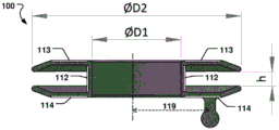
Table 1 and fig. 4a show possible dimensions of the outer diameter D2 of the distal element and/or the proximal element and the diameter D1 of the lumen 106, and the closest distance (h) between the proximal element 101 and the distal element 102. Dimensions are given for the respective puncture size. In fig. 4a, 4d, 4e, the proximal and distal discs have similar or identical diameters, but the diameters of the discs may be different and vary according to the needs of the application. For example, figure 4b shows a larger proximal disc. Alternatively, the distal disc may be larger than the proximal disc.
Table 1:
Figure BDA0002717320620000111
Figure BDA0002717320620000121
fig. 5a-c, 6a-c, 7a-c and 8a-c are further illustrations of the blood flow regulating device 100 described above. The diameters D1 and D2 are shown in fig. 5 a. D1 may be varied to provide the desired flow in the shunt, while D2 is varied to provide adequate anchoring of the device at the separation. Further dimensions of the device 100 are discussed with reference to fig. 6a-c, 7a-c and 8 a-c. For example, referring to FIG. 6a, dimension D9 is the angular distance between the peaks of two adjacent Nitinol filaments (loops) 115 that are formed to create the distal cell 102 of the flow control device 100. Dimension D10 is intended as a reference for the nitinol wire diameter, which may vary depending on the device size. Turning to FIG. 5b, dimension D4 is the diameter of connecting element 109, connecting element 109 being used to connect the flow control device to the push-type cable of the catheter for device implantation. Dimension D5 is the distance between the proximal element surface 101' of the proximal element 101 and the connecting element 109. As shown in fig. 6b, for example, dimension D6 is the thickness of the membrane 114 on the proximal element 101 of the flow control device 100. The thickness of the membrane 113 on the distal element 102 is not indicated, but the thickness of the two membranes can be equal. Turning to fig. 7b, dimension D8 is the thickness of the frame between the lumen diameter D1 and the waist diameter of the third element 105. As shown in fig. 5a, dimension D3 is the distance between the outer tangent of the flow control device diameter and the center of the connecting element 109. Fig. 7a-c show a flow control device 100 having a lumen 106 with a larger diameter than the device 100 shown in, for example, fig. 5a-c and 6a-c, and thus serving to provide a larger opening. Fig. 8a-c show a flow control device 100 for creating a hole in a body with a longer connecting neck, i.e. with a longer dimension (h), for different applications, such as a Posterior Descending Artery (PDA) stent. Typically, the two discs on either side of the device provide maximum support with clamping force and with a very limited distance between the discs, ensuring improved anchoring and stability of the device after implantation, and maintaining a calibrated size of the passage.
Fig. 10 illustrates a method 200 of manufacturing the blood flow regulator 100. The method includes braiding 201 a tubular braid of wires, wherein opposite ends of each wire are disposed at a proximal end of the tubular braid and loops of the wires are disposed at a distal end of the tubular braid. The method comprises the following steps: a distal disc 102 forming a distal end of the tubular braid 202; a proximal disc 101 forming the proximal end of the tubular braid 203. The method 200 further comprises: forming 204 a central bore 103, 104 in each of the distal and proximal discs such that the bores are joined by a central channel 106 of the tubular braid; extending between the discs; and securing 205 the opposite end of the wire in the connecting element 109 at the proximal disc and spaced an offset distance 119 from the central axis 108 extending through the passage. The offset distance 119 is shown in fig. 4a and may be varied as needed to provide an optimal location for the connecting element 109.
The method 200 may further include: the braid at the periphery 110 of the distal element 102 is folded 206 radially inward to form a double braid 111 around the periphery 110 of the distal element 102.
Various flow control devices 100 of the present disclosure are used in medical procedures to provide a shunt within the body, for example, in the atrial septum. The medical procedure in question may also include the following steps. A constraining catheter is used to position the flow control device. A push-type cable is positioned into a constraining catheter adjacent the device. The constraining catheter, push-type cable and device are inserted into the body at a percutaneous site. The distal end of the constraining catheter is positioned at the target site and the device is positioned within a body opening created by a previous interventional method, such as an ostomy.
A push-type cable is used to push the device through the constraining catheter until the device is released such that the distal element of the device is positioned inside the rupture. The push-type cable and constraining catheter are removed so that the distal end of the distal unit of the device is located inside the fracture to be formed by the device. Fig. 9 shows a side view of a catheter suitable for use in the medical procedure described above for closing an aperture in a body. The catheter is used to deliver a flow control device, also referred to as a blood flow regulating device 100, to a desired location and perform precise implantation. In one exemplary use, the delivery sheath is placed in a puncture in the arterial septum by a guidewire. A push-on cable with plastic torque control is used to advance the flow control device to the desired position and deploy the flow control device when it is advanced to the correct position.
The present disclosure has been described above with reference to specific embodiments. However, other embodiments than the above described are equally possible within the scope of this disclosure. Different method steps than those described above may be provided within the scope of the present disclosure. The different features and steps of the disclosure may be combined in other combinations than those described. The scope of the present disclosure is limited only by the appended patent claims. More generally, those skilled in the art will readily appreciate that all parameters, dimensions, materials, and configurations described herein are meant to be exemplary and that the actual parameters, dimensions, materials, and/or configurations will depend upon the specific application or applications for which the teachings of the present disclosure are used.

Claims (19)

1. A blood flow regulator (100) for creating a shunt in a heart, the blood flow regulator (100) comprising:
having a substantially disc-shaped proximal element (101),
has a generally disc-shaped distal element (102), an
A third element (105) defining a neck between the proximal and distal elements and forming a central passage (106) having a diameter no greater than the diameter of each of the distal and proximal elements;
wherein the proximal element, the distal element and the third element are formed from the same braid of more than one wire,
wherein opposite ends of each of the more than one wires are secured in a connecting element,
wherein the proximal element (101) comprises the connecting element, and wherein the connecting element is located at the proximal element, spaced apart from a central axis (108) extending through the central passage by an offset distance (119).
2. The blood flow regulator according to claim 1, wherein the connecting element is a single connecting element.
3. Blood flow regulator according to claim 1, wherein said proximal element is defined by a braid of more than one wire extending around a central hole (103) of said proximal element.
4. The blood flow regulator according to claim 1, wherein said distal element is defined by a braid of more than one wire extending around a central bore (104) of said distal element.
5. The blood flow regulator according to claim 1, further comprising a membrane (112) disposed around the central channel.
6. Blood flow regulator according to claim 1, wherein the distal element further comprises a membrane (113) promoting endothelialization and/or wherein the proximal element further comprises a membrane (114) promoting endothelialization.
7. The blood flow regulator according to any of claims 1-6, wherein the third element is elastic such that it is deformable into a non-circular shape in a septum of a heart, and/or wherein the third element has an at least partially elliptical cross-section.
8. The blood flow regulator according to claim 7, wherein the third element is deformable into an at least partially elliptical shape in a septum of a heart.
9. The blood flow regulator according to claim 1, wherein the connecting element is joined to the proximal element via a flexible element (117), the flexible element (117) being formed by the more than one wire fixed to the connecting element.
10. The blood flow regulator according to claim 1, wherein the connecting element is formed by a weld having an at least partially spherical shape.
11. The blood flow regulator according to any of claims 1-6, wherein the distal element comprises an at least partially concave shape (118) concave in a direction towards the proximal element.
12. The blood flow regulator according to any of claims 3-4, wherein the central bore is concentrically disposed in the distal element and the proximal element.
13. The blood flow regulator according to any of claims 1-5, wherein the proximal element has an elliptical shape, and/or wherein the distal element has an elliptical shape.
14. The blood flow regulator according to claim 6, wherein the membrane (113, 114) comprises at least one of: a partially biodegradable material; a filament; an elastic polymeric material; or one or more natural fabrics.
15. The blood flow regulator according to claim 14, wherein the membrane comprises a resilient polymeric material selected from the group consisting of nylon, polyester, polypropylene, polytetrafluoroethylene.
16. The blood flow regulator according to claim 15, wherein the polytetrafluoroethylene comprises expanded polytetrafluoroethylene.
17. The blood flow regulator of claim 1, wherein the proximal element and the distal element are inflatable, and the proximal element has a lower inflation strength than the distal element.
18. A method (200) of making a blood flow regulator (100), comprising:
braiding (201) a tubular braid of wires, wherein opposite ends of each wire are arranged at a proximal end of the tubular braid and loops of the wires are arranged at a distal end of the tubular braid;
forming (202) a distal disc of the distal end portion of the tubular braid;
forming (203) a proximal disc of the proximal portion of the tubular braid;
forming (204) a central hole in each of the distal and proximal discs such that the holes are joined by a central channel (106) of the tubular braid extending between the discs;
securing (205) the opposite end of each wire in a connecting element located at the proximal disc, spaced an offset distance (119) from a central axis (108) extending through the central passage.
19. The method of claim 18, further comprising:
folding the braid radially inward at a perimeter (110) of at least one of the distal and proximal discs to form a double braid around the perimeter.
CN202011077936.6A 2014-09-09 2015-09-09 Flow regulating device in heart Pending CN112220505A (en)

Applications Claiming Priority (5)

Application Number Priority Date Filing Date Title
US201462047843P 2014-09-09 2014-09-09
US62/047,843 2014-09-09
US201462077680P 2014-11-10 2014-11-10
US62/077,680 2014-11-10
CN201580048173.3A CN106714698B (en) 2014-09-09 2015-09-09 Flow-regulating device in the heart

Related Parent Applications (1)

Application Number Title Priority Date Filing Date
CN201580048173.3A Division CN106714698B (en) 2014-09-09 2015-09-09 Flow-regulating device in the heart

Publications (1)

Publication Number Publication Date
CN112220505A true CN112220505A (en) 2021-01-15

Family

ID=54062763

Family Applications (2)

Application Number Title Priority Date Filing Date
CN202011077936.6A Pending CN112220505A (en) 2014-09-09 2015-09-09 Flow regulating device in heart
CN201580048173.3A Active CN106714698B (en) 2014-09-09 2015-09-09 Flow-regulating device in the heart

Family Applications After (1)

Application Number Title Priority Date Filing Date
CN201580048173.3A Active CN106714698B (en) 2014-09-09 2015-09-09 Flow-regulating device in the heart

Country Status (8)

Country Link
US (3) US10595999B2 (en)
EP (3) EP3431051B1 (en)
JP (1) JP6577574B2 (en)
CN (2) CN112220505A (en)
CA (1) CA2960333C (en)
ES (2) ES2888910T3 (en)
TR (1) TR201815290T4 (en)
WO (1) WO2016038115A1 (en)

Cited By (1)

* Cited by examiner, † Cited by third party
Publication number Priority date Publication date Assignee Title
WO2023159744A1 (en) * 2022-02-25 2023-08-31 晨兴(南通)医疗器械有限公司 Rivet-free atrial shunt

Families Citing this family (105)

* Cited by examiner, † Cited by third party
Publication number Priority date Publication date Assignee Title
CN104971390B (en) 2004-02-03 2018-03-16 V波有限公司 Apparatus and method for pressure in control volume
US9681948B2 (en) 2006-01-23 2017-06-20 V-Wave Ltd. Heart anchor device
US12453626B2 (en) 2009-05-04 2025-10-28 V-Wave Ltd. Shunt for redistributing atrial blood volume
EP2427143B1 (en) 2009-05-04 2017-08-02 V-Wave Ltd. Device for regulating pressure in a heart chamber
US9034034B2 (en) 2010-12-22 2015-05-19 V-Wave Ltd. Devices for reducing left atrial pressure, and methods of making and using same
US12186176B2 (en) 2009-05-04 2025-01-07 V-Wave Ltd. Shunt for redistributing atrial blood volume
US8579964B2 (en) 2010-05-05 2013-11-12 Neovasc Inc. Transcatheter mitral valve prosthesis
US9554897B2 (en) 2011-04-28 2017-01-31 Neovasc Tiara Inc. Methods and apparatus for engaging a valve prosthesis with tissue
US9308087B2 (en) 2011-04-28 2016-04-12 Neovasc Tiara Inc. Sequentially deployed transcatheter mitral valve prosthesis
US11135054B2 (en) 2011-07-28 2021-10-05 V-Wave Ltd. Interatrial shunts having biodegradable material, and methods of making and using same
US9345573B2 (en) 2012-05-30 2016-05-24 Neovasc Tiara Inc. Methods and apparatus for loading a prosthesis onto a delivery system
US9572665B2 (en) 2013-04-04 2017-02-21 Neovasc Tiara Inc. Methods and apparatus for delivering a prosthetic valve to a beating heart
EP2999412B1 (en) 2013-05-21 2020-05-06 V-Wave Ltd. Apparatus for delivering devices for reducing left atrial pressure
US10675450B2 (en) 2014-03-12 2020-06-09 Corvia Medical, Inc. Devices and methods for treating heart failure
EP3171786B1 (en) 2014-07-23 2020-05-13 Corvia Medical, Inc. Devices for treating heart failure
WO2016038115A1 (en) 2014-09-09 2016-03-17 Occlutech Holding Ag A flow regulating device in the heart
WO2016178171A1 (en) 2015-05-07 2016-11-10 The Medical Research Infrastructure And Health Services Fund Of The Tel-Aviv Medical Center Temporary interatrial shunts
EP3389557B1 (en) 2015-12-15 2022-07-13 Neovasc Tiara Inc. Transseptal delivery system
US10433952B2 (en) 2016-01-29 2019-10-08 Neovasc Tiara Inc. Prosthetic valve for avoiding obstruction of outflow
US10835394B2 (en) 2016-05-31 2020-11-17 V-Wave, Ltd. Systems and methods for making encapsulated hourglass shaped stents
US20170340460A1 (en) 2016-05-31 2017-11-30 V-Wave Ltd. Systems and methods for making encapsulated hourglass shaped stents
JP2019523119A (en) 2016-08-03 2019-08-22 ピーアイ−ハーベスト ホールディング アクチェンゲゼルシャフト System and method for non-invasively measuring body pressure, including blood pressure in blood vessels
EP3524164A1 (en) 2016-08-03 2019-08-14 PI-Harvest Holding AG A system, method and software for non-invasive measurement of intravascular, in particular intracardiac blood pressure
CN113893064A (en) 2016-11-21 2022-01-07 内奥瓦斯克迪亚拉公司 Methods and systems for rapid retrieval of transcatheter heart valve delivery systems
CN106510777A (en) * 2016-12-09 2017-03-22 上海形状记忆合金材料有限公司 Atrial shunt
CN108261214B (en) * 2016-12-31 2020-06-12 先健科技(深圳)有限公司 Occluder and suturing method of occluder
US11135410B2 (en) * 2017-02-26 2021-10-05 Corvia Medical, Inc. Devices and methods for treating heart failure
US11291807B2 (en) 2017-03-03 2022-04-05 V-Wave Ltd. Asymmetric shunt for redistributing atrial blood volume
JP7033145B2 (en) 2017-03-03 2022-03-09 ブイ-ウェーブ リミテッド Shunt to redistribute atrial blood volume
CA3073834A1 (en) 2017-08-25 2019-02-28 Neovasc Tiara Inc. Sequentially deployed transcatheter mitral valve prosthesis
EP3459469A1 (en) 2017-09-23 2019-03-27 Universität Zürich Medical occluder device
US12402885B2 (en) 2017-09-23 2025-09-02 Universität Zürich Medical occlusion device
US10898698B1 (en) 2020-05-04 2021-01-26 V-Wave Ltd. Devices with dimensions that can be reduced and increased in vivo, and methods of making and using the same
US11744589B2 (en) 2018-01-20 2023-09-05 V-Wave Ltd. Devices and methods for providing passage between heart chambers
US11458287B2 (en) 2018-01-20 2022-10-04 V-Wave Ltd. Devices with dimensions that can be reduced and increased in vivo, and methods of making and using the same
WO2019195860A2 (en) 2018-04-04 2019-10-10 Vdyne, Llc Devices and methods for anchoring transcatheter heart valve
US11071627B2 (en) 2018-10-18 2021-07-27 Vdyne, Inc. Orthogonally delivered transcatheter heart valve frame for valve in valve prosthesis
US10321995B1 (en) 2018-09-20 2019-06-18 Vdyne, Llc Orthogonally delivered transcatheter heart valve replacement
US11278437B2 (en) 2018-12-08 2022-03-22 Vdyne, Inc. Compression capable annular frames for side delivery of transcatheter heart valve replacement
US11344413B2 (en) 2018-09-20 2022-05-31 Vdyne, Inc. Transcatheter deliverable prosthetic heart valves and methods of delivery
US10595994B1 (en) 2018-09-20 2020-03-24 Vdyne, Llc Side-delivered transcatheter heart valve replacement
US12186187B2 (en) 2018-09-20 2025-01-07 Vdyne, Inc. Transcatheter deliverable prosthetic heart valves and methods of delivery
US11109969B2 (en) 2018-10-22 2021-09-07 Vdyne, Inc. Guidewire delivery of transcatheter heart valve
US11737872B2 (en) 2018-11-08 2023-08-29 Neovasc Tiara Inc. Ventricular deployment of a transcatheter mitral valve prosthesis
US11253359B2 (en) 2018-12-20 2022-02-22 Vdyne, Inc. Proximal tab for side-delivered transcatheter heart valves and methods of delivery
IT201800020707A1 (en) * 2018-12-21 2020-06-21 Eustaquio Maria Onorato Patent foramen ovale occlusion device.
EP3906085A4 (en) 2019-01-04 2022-09-28 Shifamed Holdings, LLC INTERNAL RECHARGING SYSTEMS AND USE PROCEDURES
WO2020146842A1 (en) 2019-01-10 2020-07-16 Vdyne, Llc Anchor hook for side-delivery transcatheter heart valve prosthesis
US11273032B2 (en) 2019-01-26 2022-03-15 Vdyne, Inc. Collapsible inner flow control component for side-deliverable transcatheter heart valve prosthesis
US11185409B2 (en) 2019-01-26 2021-11-30 Vdyne, Inc. Collapsible inner flow control component for side-delivered transcatheter heart valve prosthesis
AU2020231221B2 (en) 2019-03-05 2025-07-31 Vdyne, Inc. Tricuspid regurgitation control devices for orthogonal transcatheter heart valve prosthesis
WO2020185597A1 (en) 2019-03-08 2020-09-17 Neovasc Tiara Inc. Retrievable prosthesis delivery system
US11076956B2 (en) 2019-03-14 2021-08-03 Vdyne, Inc. Proximal, distal, and anterior anchoring tabs for side-delivered transcatheter mitral valve prosthesis
US11173027B2 (en) 2019-03-14 2021-11-16 Vdyne, Inc. Side-deliverable transcatheter prosthetic valves and methods for delivering and anchoring the same
CN113811265B (en) 2019-04-01 2024-11-29 内奥瓦斯克迪亚拉公司 Prosthetic valve capable of being deployed in a controlled manner
US12226602B2 (en) 2019-04-03 2025-02-18 V-Wave Ltd. Systems for delivering implantable devices across an atrial septum
US11612385B2 (en) 2019-04-03 2023-03-28 V-Wave Ltd. Systems and methods for delivering implantable devices across an atrial septum
CN113924065B (en) 2019-04-10 2026-01-30 内奥瓦斯克迪亚拉公司 Prosthetic valve with natural blood flow
CA3138875A1 (en) 2019-05-04 2020-11-12 Vdyne, Inc. Cinch device and method for deployment of a side-delivered prosthetic heart valve in a native annulus
WO2020236931A1 (en) 2019-05-20 2020-11-26 Neovasc Tiara Inc. Introducer with hemostasis mechanism
CN114096205B (en) 2019-05-20 2024-05-24 V-波有限责任公司 Systems and methods for creating room shunts
EP3741312A1 (en) 2019-05-22 2020-11-25 Occlutech Holding AG Occluder with stretchable waist
WO2020257530A1 (en) 2019-06-18 2020-12-24 Shifamed Holdings, Llc Adjustable interatrial shunts and associated systems and methods
EP3986332A4 (en) 2019-06-20 2023-07-19 Neovasc Tiara Inc. Low profile prosthetic mitral valve
AU2020334080B2 (en) 2019-08-20 2025-11-27 Vdyne, Inc. Delivery and retrieval devices and methods for side-deliverable transcatheter prosthetic valves
CN111493944A (en) * 2019-08-22 2020-08-07 上海锦葵医疗器械股份有限公司 Freely-connected plugging device with 3D printing forming framework structure and forming method
CN114568015A (en) 2019-08-22 2022-05-31 爱德华兹生命科学公司 Puncture needle
CN120531525A (en) 2019-08-26 2025-08-26 维迪内股份有限公司 Laterally deliverable transcatheter prosthetic valve and method for its delivery and anchoring
US12151071B2 (en) 2019-09-09 2024-11-26 Shifamed Holdings, Llc Adjustable shunts and associated systems and methods
WO2021046753A1 (en) * 2019-09-11 2021-03-18 武汉唯柯医疗科技有限公司 Atrial shunt decompression device, weaving device and weaving method thereof
CN110464390B (en) * 2019-09-11 2025-02-28 武汉唯柯医疗科技有限公司 Atrial shunt decompression device, knitting device and knitting method thereof
EP4033999B1 (en) 2019-09-26 2024-11-27 Universität Zürich Left atrial appendage occlusion devices
CR20220218A (en) 2019-11-14 2022-08-22 Edwards Lifesciences Corp Transcatheter medical implant delivery
US11253685B2 (en) 2019-12-05 2022-02-22 Shifamed Holdings, Llc Implantable shunt systems and methods
CN115279279B (en) * 2020-01-14 2025-08-08 斯奎德拉生命科学公司 Medical implantable atrial septal defect closure device
US11234813B2 (en) 2020-01-17 2022-02-01 Vdyne, Inc. Ventricular stability elements for side-deliverable prosthetic heart valves and methods of delivery
CN121400898A (en) 2020-02-03 2026-01-27 圣犹达医疗用品心脏病学部门有限公司 Frame and patch design for occluder with interventional channel
EP4125619A4 (en) 2020-04-02 2024-06-12 Ka Medical, LLC Method for making braided medical devices
WO2021217055A1 (en) 2020-04-23 2021-10-28 Shifamed Holdings, Llc Intracardiac sensors with switchable configurations and associated systems and methods
US12440656B2 (en) 2020-04-23 2025-10-14 Shifamed Holdings, Llc Power management for interatrial shunts and associated systems and methods
WO2021216964A1 (en) 2020-04-23 2021-10-28 Shifamed Holdings, Llc Systems and methods for radiographic monitoring of shunts
WO2022046921A1 (en) 2020-08-25 2022-03-03 Shifamed Holdings, Llc Adjustable interatrial shunts and associated systems and methods
WO2022103973A1 (en) 2020-11-12 2022-05-19 Shifamed Holdings, Llc Adjustable implantable devices and associated methods
US11234702B1 (en) 2020-11-13 2022-02-01 V-Wave Ltd. Interatrial shunt having physiologic sensor
CN113491544A (en) * 2020-11-23 2021-10-12 上海傲流医疗科技有限公司 Tissue-friendly interatrial septum shunt
CN112402062A (en) * 2020-12-10 2021-02-26 启晨(上海)医疗器械有限公司 Be used for atrium reposition of redundant personnel pressure relief device
CN114617586A (en) * 2020-12-11 2022-06-14 上海捍宇医疗科技股份有限公司 A punctureable atrial septal occluder
JP7399972B2 (en) * 2020-12-11 2023-12-18 上海捍宇医療科技股▲分▼有限公司 Punctureable atrial septal defect closure plug
US12527942B2 (en) 2021-02-01 2026-01-20 Edwards Lifesciences Corporation Pulmonary vein shunting
US12318563B1 (en) 2021-02-02 2025-06-03 Taurus Vascular, Inc. Methods and systems for transcaval treatment of aneurysms
US12310837B1 (en) 2024-01-22 2025-05-27 Taurus Vascular, Inc. Methods and systems for transcaval treatment of aneurysms
EP4291279A4 (en) * 2021-02-15 2025-01-08 The Board of Trustees of the Leland Stanford Junior University MEDICAL SHUNTS
EP4304700A4 (en) 2021-03-09 2025-03-19 Shifamed Holdings, LLC SHAPE MEMORY ACTUATORS FOR ADJUSTABLE DIVERTER SYSTEMS AND RELATED SYSTEMS AND METHODS
DE102021001416A1 (en) 2021-03-17 2022-09-22 Peter Osypka Atrial Flow Regulator
CN115212370A (en) * 2021-04-14 2022-10-21 杭州诺生医疗科技有限公司 Diverting device and diverting system
US20240252792A1 (en) * 2021-05-21 2024-08-01 Shifamed Holdings, Llc Implantable medical devices having canisters enclosed in anchors with cavities, and associated systems and methods
CN115670538A (en) * 2021-07-30 2023-02-03 上海捍宇医疗科技股份有限公司 Puncture-able atrial septal occluder and conveying system thereof
WO2023030494A1 (en) * 2021-09-02 2023-03-09 晨兴(南通)医疗器械有限公司 Atrial shunt device and manufacturing method, and atrial shunt system using shunt device
CN113729800A (en) * 2021-09-02 2021-12-03 晨兴(南通)医疗器械有限公司 Shunt device for atrium
CN116019607B (en) * 2021-11-22 2024-02-23 武汉唯柯医疗科技有限公司 Atrial shunt pressure reducing device
EP4486225A1 (en) 2022-04-14 2025-01-08 V-Wave Ltd. Interatrial shunt with expanded neck region
EP4393450A1 (en) 2022-12-29 2024-07-03 OCCLUTECH GmbH Manufacturing method for a medical implantable device and a medical implantable device and base body for such implantable device
WO2024155994A1 (en) 2023-01-20 2024-07-25 Texas Medical Center Methods and systems for transcaval treatment of aneurysms
WO2025083586A1 (en) 2023-10-18 2025-04-24 V-Wave Ltd. Hybrid devices with dimensions that can be adjusted in vivo and methods of manufacturing thereof
WO2025217959A1 (en) * 2024-04-15 2025-10-23 邢泉生 Double-disk-shaped integrally-formed degradable atrial septum foramen ovale occluder

Citations (12)

* Cited by examiner, † Cited by third party
Publication number Priority date Publication date Assignee Title
US6007544A (en) * 1996-06-14 1999-12-28 Beth Israel Deaconess Medical Center Catheter apparatus having an improved shape-memory alloy cuff and inflatable on-demand balloon for creating a bypass graft in-vivo
WO2001072367A1 (en) * 2000-03-27 2001-10-04 Aga Medical Corporation Retrievable self expanding shunt
CN2464273Y (en) * 2001-01-18 2001-12-12 康云帆 Cardiac partition defect reparing support
US20030032976A1 (en) * 2001-05-21 2003-02-13 Boucek Mark M. Catheter deployed partial occlusion devices and methods
US20060224183A1 (en) * 2003-01-21 2006-10-05 Franz Freudenthal Implantable device
EP1849440A1 (en) * 2006-04-28 2007-10-31 Younes Boudjemline Vascular stents with varying diameter
CN101410064A (en) * 2006-03-24 2009-04-15 奥特鲁泰克有限公司 Occluder and method for producing same
US20100312333A1 (en) * 2009-04-29 2010-12-09 The Cleveland Clinic Foundation Apparatus and method for replacing a diseased cardiac valve
CN102802538A (en) * 2009-06-22 2012-11-28 戈尔企业控股股份有限公司 Seals and delivery systems
CN103930042A (en) * 2011-09-09 2014-07-16 奥特鲁泰克控股有限公司 A collapsible medical closing device, a method and a medical system for delivering an object
CN103945774A (en) * 2011-09-22 2014-07-23 奥特鲁泰克控股有限公司 Medical implantable occlusion device, and method for implantation thereof
CN104274262A (en) * 2014-09-01 2015-01-14 王垒 Retention device for constructing abnormal heart channel

Family Cites Families (14)

* Cited by examiner, † Cited by third party
Publication number Priority date Publication date Assignee Title
US6123715A (en) 1994-07-08 2000-09-26 Amplatz; Curtis Method of forming medical devices; intravascular occlusion devices
GB9614950D0 (en) 1996-07-16 1996-09-04 Anson Medical Ltd A ductus stent and delivery catheter
JP2005508201A (en) 2001-03-08 2005-03-31 アトリテック, インコーポレイテッド Atrial filter implant
US6638257B2 (en) 2002-03-01 2003-10-28 Aga Medical Corporation Intravascular flow restrictor
US20050165344A1 (en) * 2003-11-26 2005-07-28 Dobak John D.Iii Method and apparatus for treating heart failure
US8100938B2 (en) * 2005-11-14 2012-01-24 Occlutech Holding Ag Occlusion device for occluding an atrial auricula and method for producing same
US9681948B2 (en) * 2006-01-23 2017-06-20 V-Wave Ltd. Heart anchor device
DE102006045545A1 (en) * 2006-09-25 2008-04-03 Peter Osypka Stiftung Stiftung des bürgerlichen Rechts Medical device
DE102006050385A1 (en) * 2006-10-05 2008-04-10 pfm Produkte für die Medizin AG Implantable mechanism for use in human and/or animal body for e.g. closing atrium septum defect, has partial piece that is folded back on another partial piece from primary form into secondary form of carrying structure
US20090082803A1 (en) * 2007-09-26 2009-03-26 Aga Medical Corporation Braided vascular devices having no end clamps
CN101951858B (en) * 2008-02-25 2015-02-11 麦德托尼克瓦斯科尔勒公司 Infundibular reducer devices
US9186152B2 (en) 2010-11-12 2015-11-17 W. L. Gore & Associates, Inc. Left atrial appendage occlusive devices
CN103705274B (en) * 2013-12-20 2017-03-29 先健科技(深圳)有限公司 Plugging device
WO2016038115A1 (en) 2014-09-09 2016-03-17 Occlutech Holding Ag A flow regulating device in the heart

Patent Citations (13)

* Cited by examiner, † Cited by third party
Publication number Priority date Publication date Assignee Title
US6007544A (en) * 1996-06-14 1999-12-28 Beth Israel Deaconess Medical Center Catheter apparatus having an improved shape-memory alloy cuff and inflatable on-demand balloon for creating a bypass graft in-vivo
WO2001072367A1 (en) * 2000-03-27 2001-10-04 Aga Medical Corporation Retrievable self expanding shunt
CN1358482A (en) * 2000-03-27 2002-07-17 Aga医疗有限公司 Recoverable self-extending flow-dividing device
CN2464273Y (en) * 2001-01-18 2001-12-12 康云帆 Cardiac partition defect reparing support
US20030032976A1 (en) * 2001-05-21 2003-02-13 Boucek Mark M. Catheter deployed partial occlusion devices and methods
US20060224183A1 (en) * 2003-01-21 2006-10-05 Franz Freudenthal Implantable device
CN101410064A (en) * 2006-03-24 2009-04-15 奥特鲁泰克有限公司 Occluder and method for producing same
EP1849440A1 (en) * 2006-04-28 2007-10-31 Younes Boudjemline Vascular stents with varying diameter
US20100312333A1 (en) * 2009-04-29 2010-12-09 The Cleveland Clinic Foundation Apparatus and method for replacing a diseased cardiac valve
CN102802538A (en) * 2009-06-22 2012-11-28 戈尔企业控股股份有限公司 Seals and delivery systems
CN103930042A (en) * 2011-09-09 2014-07-16 奥特鲁泰克控股有限公司 A collapsible medical closing device, a method and a medical system for delivering an object
CN103945774A (en) * 2011-09-22 2014-07-23 奥特鲁泰克控股有限公司 Medical implantable occlusion device, and method for implantation thereof
CN104274262A (en) * 2014-09-01 2015-01-14 王垒 Retention device for constructing abnormal heart channel

Non-Patent Citations (1)

* Cited by examiner, † Cited by third party
Title
MEHUL B. PATEL: "Implantable atrial flow regulator for severe, irreversible pulmonary arterial hypertension", EUROINTERVENTION, vol. 2015, no. 11, 31 July 2015 (2015-07-31), pages 706 - 709, XP055932850 *

Cited By (1)

* Cited by examiner, † Cited by third party
Publication number Priority date Publication date Assignee Title
WO2023159744A1 (en) * 2022-02-25 2023-08-31 晨兴(南通)医疗器械有限公司 Rivet-free atrial shunt

Also Published As

Publication number Publication date
EP3431051B1 (en) 2021-09-01
ES2690259T3 (en) 2018-11-20
US20170273790A1 (en) 2017-09-28
EP3922218A1 (en) 2021-12-15
CN106714698B (en) 2020-11-03
US10595999B2 (en) 2020-03-24
US20200268515A1 (en) 2020-08-27
CA2960333A1 (en) 2016-03-17
JP6577574B2 (en) 2019-09-18
JP2017529908A (en) 2017-10-12
WO2016038115A1 (en) 2016-03-17
EP3193791B1 (en) 2018-08-22
CA2960333C (en) 2023-02-14
TR201815290T4 (en) 2018-11-21
US11839526B2 (en) 2023-12-12
EP3431051A1 (en) 2019-01-23
US20240065840A1 (en) 2024-02-29
EP3193791A1 (en) 2017-07-26
ES2888910T3 (en) 2022-01-10
CN106714698A (en) 2017-05-24

Similar Documents

Publication Publication Date Title
US20240065840A1 (en) Flow regulating device in the heart
US20250341037A1 (en) Braided Medical Device And Manufacturing Method Thereof
US10905406B2 (en) Medical implantable occlusion device, and method for implantation thereof
US9597088B2 (en) Medical implant and manufacturing method thereof
EP2596754A1 (en) Medical implant and manufacturing method thereof
EP2819585B1 (en) A device for occluding an opening in a body and associated methods
US20250318819A1 (en) Tissue scaffolding occlusion device
HK40042657A (en) A flow regulating device in the heart

Legal Events

Date Code Title Description
PB01 Publication
PB01 Publication
SE01 Entry into force of request for substantive examination
REG Reference to a national code

Ref country code: HK

Ref legal event code: DE

Ref document number: 40042657

Country of ref document: HK

TA01 Transfer of patent application right

Effective date of registration: 20240416

Address after: Analytik Jena

Applicant after: OCCLUTECH GmbH

Country or region after: Germany

Address before: Schaffhausen, Switzerland

Applicant before: Occlutech Holding AG

Country or region before: Switzerland