EP4033999B1 - Left atrial appendage occlusion devices - Google Patents
Left atrial appendage occlusion devices Download PDFInfo
- Publication number
- EP4033999B1 EP4033999B1 EP20788902.3A EP20788902A EP4033999B1 EP 4033999 B1 EP4033999 B1 EP 4033999B1 EP 20788902 A EP20788902 A EP 20788902A EP 4033999 B1 EP4033999 B1 EP 4033999B1
- Authority
- EP
- European Patent Office
- Prior art keywords
- balloon
- occlusion device
- proximal
- actuating shaft
- radially
- Prior art date
- Legal status (The legal status is an assumption and is not a legal conclusion. Google has not performed a legal analysis and makes no representation as to the accuracy of the status listed.)
- Active
Links
Images


Classifications
-
- A—HUMAN NECESSITIES
- A61—MEDICAL OR VETERINARY SCIENCE; HYGIENE
- A61B—DIAGNOSIS; SURGERY; IDENTIFICATION
- A61B17/00—Surgical instruments, devices or methods
- A61B17/12—Surgical instruments, devices or methods for ligaturing or otherwise compressing tubular parts of the body, e.g. blood vessels or umbilical cord
- A61B17/12022—Occluding by internal devices, e.g. balloons or releasable wires
- A61B17/12131—Occluding by internal devices, e.g. balloons or releasable wires characterised by the type of occluding device
- A61B17/12168—Occluding by internal devices, e.g. balloons or releasable wires characterised by the type of occluding device having a mesh structure
- A61B17/12172—Occluding by internal devices, e.g. balloons or releasable wires characterised by the type of occluding device having a mesh structure having a pre-set deployed three-dimensional shape
-
- A—HUMAN NECESSITIES
- A61—MEDICAL OR VETERINARY SCIENCE; HYGIENE
- A61B—DIAGNOSIS; SURGERY; IDENTIFICATION
- A61B17/00—Surgical instruments, devices or methods
- A61B17/12—Surgical instruments, devices or methods for ligaturing or otherwise compressing tubular parts of the body, e.g. blood vessels or umbilical cord
- A61B17/12022—Occluding by internal devices, e.g. balloons or releasable wires
- A61B17/12099—Occluding by internal devices, e.g. balloons or releasable wires characterised by the location of the occluder
- A61B17/12122—Occluding by internal devices, e.g. balloons or releasable wires characterised by the location of the occluder within the heart
-
- A—HUMAN NECESSITIES
- A61—MEDICAL OR VETERINARY SCIENCE; HYGIENE
- A61B—DIAGNOSIS; SURGERY; IDENTIFICATION
- A61B17/00—Surgical instruments, devices or methods
- A61B17/12—Surgical instruments, devices or methods for ligaturing or otherwise compressing tubular parts of the body, e.g. blood vessels or umbilical cord
- A61B17/12022—Occluding by internal devices, e.g. balloons or releasable wires
- A61B17/12131—Occluding by internal devices, e.g. balloons or releasable wires characterised by the type of occluding device
- A61B17/12136—Balloons
-
- A—HUMAN NECESSITIES
- A61—MEDICAL OR VETERINARY SCIENCE; HYGIENE
- A61B—DIAGNOSIS; SURGERY; IDENTIFICATION
- A61B17/00—Surgical instruments, devices or methods
- A61B17/0057—Implements for plugging an opening in the wall of a hollow or tubular organ, e.g. for sealing a vessel puncture or closing a cardiac septal defect
- A61B2017/00575—Implements for plugging an opening in the wall of a hollow or tubular organ, e.g. for sealing a vessel puncture or closing a cardiac septal defect for closure at remote site, e.g. closing atrial septum defects
- A61B2017/00619—Locking means for locking the implement in expanded state
-
- A—HUMAN NECESSITIES
- A61—MEDICAL OR VETERINARY SCIENCE; HYGIENE
- A61B—DIAGNOSIS; SURGERY; IDENTIFICATION
- A61B17/00—Surgical instruments, devices or methods
- A61B17/0057—Implements for plugging an opening in the wall of a hollow or tubular organ, e.g. for sealing a vessel puncture or closing a cardiac septal defect
- A61B2017/00575—Implements for plugging an opening in the wall of a hollow or tubular organ, e.g. for sealing a vessel puncture or closing a cardiac septal defect for closure at remote site, e.g. closing atrial septum defects
- A61B2017/00632—Occluding a cavity, i.e. closing a blind opening
-
- A—HUMAN NECESSITIES
- A61—MEDICAL OR VETERINARY SCIENCE; HYGIENE
- A61B—DIAGNOSIS; SURGERY; IDENTIFICATION
- A61B17/00—Surgical instruments, devices or methods
- A61B2017/00831—Material properties
- A61B2017/00853—Material properties low friction, hydrophobic and corrosion-resistant fluorocarbon resin coating (ptf, ptfe, polytetrafluoroethylene)
-
- A—HUMAN NECESSITIES
- A61—MEDICAL OR VETERINARY SCIENCE; HYGIENE
- A61B—DIAGNOSIS; SURGERY; IDENTIFICATION
- A61B17/00—Surgical instruments, devices or methods
- A61B17/12—Surgical instruments, devices or methods for ligaturing or otherwise compressing tubular parts of the body, e.g. blood vessels or umbilical cord
- A61B17/12022—Occluding by internal devices, e.g. balloons or releasable wires
- A61B2017/1205—Introduction devices
- A61B2017/12054—Details concerning the detachment of the occluding device from the introduction device
- A61B2017/12095—Threaded connection
Definitions
- the present invention generally relates to an occlusion device for occluding a left atrial appendage.
- LAA left atrial appendage
- Percutaneous LAA occlusion is a therapy for the prevention of stroke in patients with atrial fibrillation.
- LAA occlusion is used as an alternative to, or in combination with, oral anticoagulant therapy.
- LAA occlusion has favorable clinical outcomes, but commercially-available devices are typically self-expandable, and not designed to adapt to the LAA anatomy, and thus sometimes result in complications or suboptimal outcomes. In these environments, some of the currently available occlusion devices are limited by the poor adaptability of the device to the defect (lack of conformability) and by a lack of intra-device sealing (due to the high-flow environment).
- Publication EP 3 459 469 A1 discloses an occlusion device as defined in the preamble of independent claim 1.
- PCT Publication WO 2019/057950 to Maisano et al. describes an occluder device for occluding a cardiovascular defect or a gap between a medical device and adjacent body tissue, including a compliant balloon defining a fluid-tight balloon chamber and provided with a balloon channel forming a longitudinal passage from a proximal side to a distal side of the balloon; a tip element disposed at the distal side of the balloon, a base element disposed at the proximal side of the balloon, and connecting means comprising at least one connecting strut attached to the tip element and to the base element, the tip element and the base element each having a guide opening substantially coaxial to the balloon channel for slidingly receiving therein a guidewire for the device; elongated actuating means disposed longitudinally slidable in the balloon channel, releasably connectable to the tip element, and longitudinally slidable with respect to the base element; locking means for maintaining a predetermined distance between the tip element and the base element;
- US Patent 6,652,556 to VanTassel et al. describes apparatus for permanent placement across an ostium of a left atrial appendage in a patient, which includes a filtering membrane configured to extend across the ostium of the left atrial appendage.
- the filtering membrane has a permeable structure which allows blood to flow through but substantially inhibits thrombus from passing therethrough.
- the apparatus also includes a support structure comprising a plurality of fingers which are radially outwardly expandable with respect to a longitudinal axis to permanently engage the interior wall of the left atrial appendage.
- the filtering membrane is attached to the support structure extending across the ostium of the left atrial appendage.
- Fig. 1 is a schematic illustration of an occlusion device 10 for occluding a left atrial appendage (LAA), in accordance with an application of the present invention.
- Occlusion device 10 is for use with a delivery system 20, which is described in more detail hereinbelow with reference to Figs. 3A-F .
- Delivery system 20 and the other delivery systems described herein are typically transcatheter delivery systems that enable percutaneous deployment of the occlusion devices.
- FIGs. 2A-B are schematic cross-sectional illustrations of occlusion device 10 and a distal portion of delivery system 20, in accordance with an application of the present invention.
- Fig. 2A shows occlusion device 10 with a locking mechanism 40 thereof in an unlocked state and valve 42 thereof in an open state, as described hereinbelow.
- Fig. 2B shows occlusion device 10 with locking mechanism 40 in a locked state and valve 42 in a closed state, as described hereinbelow.
- occlusion device 10 comprises:
- Occlusion device 10 is configured such that proximally longitudinally moving actuating shaft 34 expands balloon 30 in a radial or a lateral direction by shortening the distance between distal and proximal end portions 36 and 38 of balloon 30 to a desired distance.
- Locking mechanism 40 is configured, when in the locked state, to maintain, between distal end portion 36 of balloon 30 and proximal end portion 38 of balloon 30, the distance set using actuating shaft 34.
- occlusion device 10 is shaped so as to define a fluid flow path 44 along (e.g., alongside, as shown) a portion of actuating shaft 34.
- Valve 42 is configured to selectively:
- occlusion device 10 is configured such that reduction of the distance, by proximal longitudinal movement of actuating shaft 34:
- the first predetermined distance does not equal the second predetermined distance.
- the first predetermined distance may be less than the second predetermined distance, such that the proximal longitudinal movement of actuating shaft 34 first automatically transitions valve 42 from the open state to the closed state and subsequently automatically transitions locking mechanism 40 from the unlocked state to the locked state.
- the first predetermined distance may be greater than the second predetermined distance, such that this sequence is reversed.
- the first predetermined distance equals the second predetermined distance, such that the proximal longitudinal movement of actuating shaft 34 simultaneously automatically transitions valve 42 from the open state to the closed state and automatically transitions locking mechanism 40 from the unlocked state to the locked state.
- delivery system 20 comprises a pull shaft 46, which is releasably coupled a proximal end portion of actuating shaft 34.
- a distal portion of pull shaft 46 may comprise a pull-shaft coupling 48, which may, for example, be shaped so as to define a thread that removably engages a corresponding thread defined by the proximal end portion of actuating shaft 34. Rotation of pull shaft 46 disengages shaft coupling 48 from the corresponding thread defined by the proximal end portion of actuating shaft 34.
- occlusion device 10 is configured to be releasably connected to delivery system 20.
- occlusion device 10 is configured such that fluid flow path 44 is coupled in fluid communication with delivery system 20 when occlusion device 10 is releasably connected to delivery system 20, such as shown in Figs. 2A-B .
- actuating shaft 34 is shaped so as to define, at least in part, a distal tip 50 disposed at distal end portion 36 of balloon 30, as shown in Figs. 1 and 2A-B .
- occlusion device 10 further comprises a distal tip disposed at distal end portion 36 of balloon 30, and actuating shaft 34 is connected to the distal tip (configuration not shown).
- occlusion device 10 further comprises a proximal base disposed at proximal end portion 38 of balloon 30, and actuating shaft 34 is moveable (e.g., longitudinally or rotationally) with respect to the proximal base (configuration not shown).
- valve 42 is disposed along actuating shaft 34, such as shown in Figs. 2A-B .
- occlusion device 10 further comprises a proximal tube 52, which is axially fixed with respect to proximal end portion 38 of balloon 30.
- Actuating shaft 34 is slidably disposed partially within proximal tube 52, e.g., so as to indirectly connect actuating shaft 34 to proximal end portion 38 via proximal tube 52.
- occlusion device 10 is shaped so as to define fluid flow path 44 along the portion of actuating shaft 34, radially between an external surface of actuating shaft 34 and an internal surface of proximal tube 52, such as shown in Figs. 2A-B .
- valve 42 is disposed along actuating shaft 34.
- valve 42 comprises a seal 54 around at least a portion of (e.g., entirely around) the external surface of actuating shaft 34.
- Valve 42 is configured to assume (a) the open state when seal 54 is disposed at one or more first axial positions 56A with respect to proximal tube 52 (one such first axial position is shown in Fig. 2A ), and (b) the closed state when seal 54 is disposed at one or more second axial positions 56B with respect to proximal tube 52 (one such second axial position is shown in Fig. 2B ).
- the one or more second axial positions 56B are proximal to the one or more first axial positions 56A.
- seal 54 may comprise an O-ring, as shown in Figs.
- one or more additional seals 19, e.g., one or more O-rings, are provided to provide further stabilization an alignment of the distal tube inside the proximal tube by friction.
- seal 54, actuating shaft 34, and proximal tube 52 are arranged such that seal 54 blocks fluid flow out of a distal end 58 of proximal tube 52, at least when seal 54 is disposed at the one or more first axial positions 56A with respect to proximal tube 52, such as shown in Fig. 2A .
- friction between seal 54 and the inner surface of proximal tube 52 increases structural stability, and/or enables stepwise inflation/implantation.
- a wall of proximal tube 52 is shaped so as to define one or more tabs 60 through the wall.
- the one or more tabs 60 are biased to flex radially inward.
- fluid flow path 44 passes through the wall between respective proximal ends 62 of the one or more tabs 60 and a non-tabbed portion 64 of the wall axially adjacent the one or more tabs 60, such as proximal to the one or more tabs 60, as shown.
- the external surface of actuating shaft 34 is shaped so as to define one or more protrusions 66 around at least a portion of (e.g., entirely around) actuating shaft 34.
- Proximal ends 62 of the one or more tabs 60 are shaped so as to prevent distal movement of the one or more protrusions 66 when the one or more protrusions 66 are disposed proximal to the proximal ends 62 of the one or more tabs 60, such as shown in Fig. 2B , thereby causing locking mechanism 40 to assume the locked state.
- occlusion device 10 further comprises a proximal LAA-orifice cover 70, which:
- proximal LAA-orifice cover 70 This indirect connection of proximal LAA-orifice cover 70 to balloon 30 generally prevents an anodic reaction between the typically super-elastic (e.g., Nitinol) material of frame 72 of proximal LAA-orifice cover 70 and the typically plastically deformable (e.g., stainless steel) material of struts 80, described hereinbelow. Such a reaction might have occurred if the two elements were instead welded or otherwise bonded together in contact with each other.
- typically super-elastic e.g., Nitinol
- proximal LAA-orifice cover 70 is directly connected to balloon 30, such as if frame 72 comprises a different plastically-deformable material, such as titanium.
- occlusion device 10 further comprises orifice-support stent 290, described hereinbelow with reference to Figs. 8 and 9A-B .
- actuating shaft 34 is shaped so as to define a guidewire lumen 76 for slidingly receiving therein a guidewire and/or passage of liquid injected under pressure, such as contrast media injected from the proximal handle of the delivery tool to the distal end of the occlusion device.
- actuating shaft 34 is not shaped so as to define a guidewire lumen.
- compliant balloon 30 comprises a compliant material selected from the group consisting of polycaprolactone (PCL), polyglycolic acid (PGA), polylactic acid (PLA), and polydioxanone (PDO or PDS), silicone, polyurethane, polytetrafluoroethylene (PTFE), polymethylmethacrylate, polyether ether ketone (PEEK), polyvinyl chloride, polyethylene terephthalate, nylon, polyamide, polyamide, and polyether block amide (PEBA).
- PCL polycaprolactone
- PGA polyglycolic acid
- PLA polylactic acid
- PDO or PDS polydioxanone
- silicone silicone
- polyurethane polytetrafluoroethylene
- PEEK polymethylmethacrylate
- PEEK polyether ether ketone
- PEBA polyether block amide
- balloon 30 has an average wall thickness of between 100 and 5000 microns. Alternatively or additionally, for some applications, balloon 30 has, at a thinnest portion of a wall of balloon 30, a thinnest wall thickness of between 20 and 500 microns.
- occlusion device 10 further comprises connecting struts 80 fixed to distal end portion 36 of balloon 30 and to proximal end portion 38 of balloon 30.
- Struts 80 may be disposed inside balloon 30, outside balloon 30, or some inside and some outside balloon 30.
- struts 80 are arranged as a frame.
- struts 80 are arranged in a cage-like arrangement.
- struts 80 comprise a plastically-deformable material, such as stainless steel or titanium.
- struts 80 help shape balloon 30 as the balloon chamber is inflated and/or the balloon is shortened.
- occlusion device 10 is configured such that inflation of balloon chamber 32 plastically deforms connecting struts 80.
- occlusion device 10 is configured such that shortening of balloon 30 plastically deforms connecting struts 80.
- first lateral portions 81A of struts 80 arranged along a lateral surface of balloon 30 may be more compliant than second end portions 81B of struts 80 arranged on a distal surface of balloon 30 and/or on a proximal surface of balloon 30.
- first lateral portions 81A may be thinner than second end portions 81B, as shown in Fig.
- first lateral portions 81A may be shaped to be more compliant, e.g., have a serpentine (e.g., sinusoidal) shape, as shown.
- first lateral portions 81A are oriented parallel to a central longitudinal axis of occlusion device 10.
- FIGs. 3A-F are schematic illustrations of steps of a method of deploying occlusion device 10 using delivery system 20, in accordance with an application of the present invention.
- FIGS. 4A-C are schematic cross-sectional views of a portion of the steps of the method shown in Figs. 3A-F , in accordance with an application of the present invention.
- Fig. 3A schematically shows occlusion device 10 releasably disposed in a radially-compressed state within a sheath 82 of delivery system 20.
- a greatest distance between proximal end portion 38 of balloon 30 and distal end portion 36 of balloon 30 is at least 8 mm (e.g., at least 15 mm), no more than 80 mm (e.g. no more than 60 mm), and/or between 8 and 80 mm (e.g., between 15 and 60 mm), when occlusion device 10 is in this radially-compressed state.
- occlusion device 10 comprises a proximal connector 84 that is configured to releasably connect occlusion device 10 to a correspondingly configured distal connector 86 of delivery system 20.
- distal connector 86 comprises one or more legs that engage one or more respective coupling sites (e.g., slots) of proximal connector 84, such as perhaps best seen in Figs. 4A-C .
- the legs may be configured to biased radially outward when in an unconstrained, resting state, and may be held radially inward engaging the coupling sites of proximal connector 84, such as by implant catheter 88, as shown in Fig. 4A .
- Proximal withdrawal of implant catheter 88 with respect to occlusion device 10 release the legs, as shown in Fig. 4B .
- proximal connector 84 is shaped so as to define a thread (configuration not shown).
- delivery system 20 comprises an implant catheter 88 that is connected to an operating handle (not shown).
- Implant catheter 88 comprises (a) a longitudinal passageway for a guidewire, (b) distal connector 86 for releasably connecting implant catheter 88 to correspondingly configured proximal connector 84 of occlusion device 10, and (c) an inflation tube channel releasably connectable to fluid flow path 44 of occlusion device 10.
- the longitudinal passageway may alternatively or additionally be used to inject contrast media from the handle to a distal opening of the inflation tube channel distally to the balloon.
- Fig. 3B shows occlusion device 10 after sheath 82 has been proximally withdrawn, thereby releasing occlusion device 10.
- Fig. 3B also shows proximal LAA-orifice cover 70 in its radially-expanded state.
- frame 72 of proximal LAA-orifice cover 70 comprises a shape-memory memory, e.g., a super-elastic metal, which causes cover 70 to automatically transition to the radially-expanded state upon release from sheath 82.
- Balloon 30 remains in a non-inflated, elongate configuration at this stage of deployment.
- a healthcare worker places the distal end of occlusion device 10 into the LAA, using delivery system navigation.
- Figs. 3C-D the healthcare worker inflates balloon chamber 32.
- Fig. 3C shows occlusion device 10 upon partial inflation of balloon chamber 32
- Fig. 3D shows occlusion device 10 upon complete inflation of balloon chamber 32.
- Balloon 30 may be inflated by filling balloon chamber 32 with any fluid, including but not limited to saline solution (optionally comprising a contrast medium), blood (e.g., autologous blood), foam, and/or a glue (e.g., a gel, a liquid polymer that can change its proprieties to become rigid, or a hydrogel that remains a gel or self-cures at body temperature).
- saline solution optionally comprising a contrast medium
- blood e.g., autologous blood
- foam e.g., a glue
- a glue e.g., a gel, a liquid polymer that can change its proprieties to become rigid, or a hydrogel that remains a gel or self-cures at body temperature
- struts 80 are shaped so as to define a plurality of spikes 89 that are initially generally axially oriented, as shown in Fig. 3C , and are configured to extend more radially upon expansion of balloon 30 to serve as tissue-engaging barbs, as shown in Fig. 3D .
- Figs. 3E and 4A show occlusion device 10 after (a) valve 42 has transitioned from the open state to the closed state, (b) actuating shaft 34 has been proximally longitudinally moved to expand balloon 30 in a radial or a lateral direction by shortening the distance between distal and proximal end portions 36 and 38 of balloon 30 to a desired distance, and (c) locking mechanism 40 has transitioned from the unlocked state to the locked state, as described hereinabove with reference to Figs. 2A-B .
- actuating shaft 34 is proximally longitudinally moved to expand balloon 30 in a radial or a lateral direction by shortening the distance between distal and proximal end portions 36 and 38 of balloon 30 to a desired distance.
- Proximal connector 84 of occlusion device 10 is still releasably connected to correspondingly configured distal connector 86 of delivery system 20.
- Figs. 3F and 4B-C show occlusion device 10 after proximal connector 84 of occlusion device 10 has been released from distal connector 86 of delivery system 20.
- Fig. 4C also shows occlusion device 10 after pull shaft 46 has been decoupled from the proximal end portion of actuating shaft 34, such as by rotating pull shaft 46 to unscrew it, as described hereinabove.
- Fig. 5 is a schematic illustration of occlusion device 10 implanted to occlude an LAA 100, in accordance with an application of the present invention.
- balloon 30 is disposed within LAA 100
- proximal LAA-orifice cover 70 is disposed in a left atrium 102 outside LAA 100, against the atrial wall surrounding the orifice of LAA 100, thereby creating a continuum with the atrium at the LAA level.
- proximal LAA-orifice cover 70 protrudes only minimally because of its relatively flat shape, so as not to interfere with blood flow and not to cause thrombosis.
- struts 80 provide most of the anchoring of occlusion device 10, and balloon 30 provides most of the sealing of the LAA.
- proximal LAA-orifice cover 70 provides additional sealing of the LAA, primarily to inhibit creation of thrombi on the balloon surface at the orifice level.
- proximal LAA-orifice cover 70 is asymmetric about proximal tube 52, e.g., elliptical or with a radius greater in one direction than in the perpendicular direction.
- proximal LAA-orifice cover 70 is configured to have an adjustable greatest dimension measured perpendicular to proximal tube 52. For example, rotation of a proximal LAA-orifice cover 70 adjustment mechanism may adjust the greatest dimension.
- covering 74 of proximal LAA-orifice cover 70 is blood-permeable, so as to serve as filter for the passage of blood in and out of the LAA.
- covering 74 is not blood-permeable, so as to create a secondary sealing of the LAA in addition to the sealing provided by balloon 30.
- proximal LAA-orifice cover 70 is bioresorbable and/or drug-eluting.
- FIG. 6 is a schematic illustration of an occlusion device 110 for occluding an LAA, in accordance with an application of the present invention.
- Occlusion device 110 is for use with a delivery system 120.
- occlusion device 110 is similar to occlusion device 10, described hereinabove with reference to Figs. 1-5 , and may implement any of the features thereof, mutatis mutandis.
- delivery system 120 is similar to delivery system 20, described hereinabove with reference to Figs. 1-5 , and may implement any of the features thereof, mutatis mutandis.
- Like reference numerals refer to like parts.
- FIGs. 7A-C are schematic cross-sectional illustrations of occlusion device 110 and a distal portion of delivery system 120, in accordance with an application of the present invention.
- Figs. 7A-B show occlusion device 110 connected to delivery system 120, with valve 142 of occlusion device 110 in an open state, as described hereinbelow.
- Fig. 7A shows occlusion device 110 with balloon 130 thereof in an elongated state
- Figs. 7B-C show occlusion device 110 with balloon 130 in a shortened state.
- Fig. 7C shows occlusion device 110 connected to delivery system 120, with valve 142 in a closed state.
- occlusion device 110 comprises:
- Occlusion device 110 is shaped so as to define a fluid flow path 144 having one or more fluid-flow-path openings 145 to balloon chamber 132.
- occlusion device 110 is configured such that fluid flow path 144 is coupled in fluid communication with delivery system 120 when occlusion device 110 is releasably connected to delivery system 120.
- elastomer sleeve 143 may comprise silicone.
- Elastomer sleeve 143 is configured to have a resting state in which the sleeve covers and seals the one or more fluid-flow-path openings 145, such that valve 142 is in a closed state, as shown in Fig. 7C .
- Delivery system 120 is configured to be releasably connected to occlusion device 110.
- Delivery system 120 comprises a valve-opening prop 147, which is configured:
- valve-opening prop 147 e.g., tubular portion 151 thereof, described below is fixed to pull shaft 46.
- valve-opening prop 147 comprises one or more tabs 149 that extend radially outward from an axis of elastomer sleeve 143, so as to prop open elastomer sleeve 143.
- valve-opening prop 147 is configured such that axial sliding thereof with respect to elastomer sleeve 143 (e.g., in a proximal direction) transitions valve-opening prop 147 from the propping position to the non-propping position, as shown in the transition between Fig. 7B and Fig. 7C .
- occlusion device 110 further comprises a proximal tube 152, which is axially fixed with respect to proximal end portion 138 of balloon 130.
- actuating shaft 134 is slidably disposed partially within proximal tube 152.
- a seal such as an O-ring (as shown), is provided, and friction between the seal and the inner surface of a proximal tube 152 increases structural stability.
- the O-ring upon completion of the shortening of the balloon, is disposed proximal to the one or more fluid-flow-path openings 145 and blocks additional fluid from passing through the one or more fluid-flow-path openings 145 and elastomer sleeve 143.
- valve-opening prop 147 comprises a tubular portion 151, which is disposed at least partially within proximal tube 152.
- valve-opening prop 147 comprises the one or more tabs 149, which extend (a) axially away from tubular portion 151 (e.g., in a distal direction) and (b) radially outward from proximal tube 152, so as to prop open elastomer sleeve 143.
- the one or more tabs 149 pass through at least a portion of the one or more fluid-flow-path openings 145 when valve-opening prop 147 is in the propping position, such as shown in Figs. 6 and 7A-B .
- proximal tube 152 is shaped so as to define one or more access openings through a wall of proximal tube 152, and the one or more tabs 149 pass through the one or more access openings at least when valve-opening prop 147 is in the propping position (configuration not shown).
- occlusion device 110 further comprises proximal LAA-orifice cover 70, which is fixed to proximal tube 152 radially surrounding proximal tube 152.
- Proximal LAA-orifice cover 70 may implement any of the techniques described hereinabove and/or hereinbelow.
- occlusion device 110 further comprises an orifice-support stent 290, described hereinbelow with reference to Figs. 8 and 9A-B .
- occlusion device 110 further comprises a locking mechanism, which is configured to assume locked and unlocked states, and which is configured, when in the locked state, to maintain, between distal end portion 136 of balloon 130 and proximal end portion 138 of balloon 130, the distance set using actuating shaft 134.
- the locking mechanism may implement any of the locking mechanisms described herein, mutatis mutandis.
- actuating shaft 134 is shaped so as to define, at least in part, a distal tip 150 disposed at distal end portion 136 of balloon 130.
- occlusion device 110 further comprises connecting struts 180 fixed to distal end portion 136 of balloon 130 and to proximal end portion 138 of balloon 130.
- occlusion device 110 is configured such that inflation of balloon chamber 132 plastically deforms connecting struts 180.
- occlusion device 110 is configured such that shortening of balloon 130 plastically deforms connecting struts 180.
- delivery system 120 further comprising implant catheter 88, such as described hereinabove with reference to Figs. 1-5 .
- Fig. 7D is a schematic illustration of an occlusion device 410 for occluding an LAA, in accordance with an application of the present invention.
- Occlusion device 410 is for use with a delivery system.
- occlusion device 410 is similar to occlusion device 110, described hereinabove with reference to Figs. 6 and 7A-C , and may implement any of the features thereof, mutatis mutandis.
- Like reference numerals refer to like parts.
- the delivery system is similar to delivery system 20, described hereinabove with reference to Figs. 1-5 , and may implement any of the features thereof, mutatis mutandis.
- Occlusion device 410 comprises a valve 442, comprising elastomer sleeve 143 that surrounds a portion of actuating shaft 134.
- Elastomer sleeve 143 is configured to have a resting state in which the sleeve covers and seals the one or more fluid-flow-path openings 145, such that the valve is in a closed state (not shown in Fig. 7D , but similar to the state shown in Fig. 7C for occlusion device 110).
- the delivery system of the present configuration does not comprise valve-opening prop 147. Instead, the delivery system comprises one or more guidewires 447, which:
- the one or more guidewires 447 pass through at least a portion of the one or more fluid-flow-path openings 145 when the one or more guidewires are in the propping position.
- FIG. 8 is a schematic illustration of an occlusion device 210 for occluding an LAA, in accordance with an application of the present invention.
- Occlusion device 210 is for use with a delivery system 220.
- Like reference numerals refer to like parts.
- FIGs. 9A-B are schematic cross-sectional illustrations of occlusion device 210 and a distal portion of delivery system 220, in accordance with an application of the present invention.
- Fig. 9A-B show occlusion device 210 connected to delivery system 220.
- Fig. 9A shows occlusion device 210 with balloon 230 thereof in an elongated state
- Fig. 9B shows occlusion device 210 with balloon 230 in a shortened state.
- Occlusion device 210 comprises:
- Occlusion device 210 further comprises proximal LAA-orifice cover 70, which (a) is configured to assume a radially-compressed state and a radially-expanded state, (b) comprises frame 72 and covering 74 fixed to frame 72, and (c) when in the radially-expanded state, is generally orthogonal to actuating shaft 234 and has a greatest dimension, measured perpendicular to actuating shaft 234, of at least 10 mm (e.g., at least 20 mm), no more than 50 mm (e.g., no more than 30 mm), and/or between 10 and 50 mm (e.g., between 20 and 30 mm).
- proximal LAA-orifice cover 70 which (a) is configured to assume a radially-compressed state and a radially-expanded state, (b) comprises frame 72 and covering 74 fixed to frame 72, and (c) when in the radially-expanded state, is generally orthogonal
- Occlusion device 210 still further comprises an orifice-support stent 290, which is configured to enhance support at the orifice of the LAA.
- Orifice-support stent 290 is configured to be positioned at least partially within the LAA, such as entirely within the LAA.
- Orifice-support stent 290 is:
- generally cylindrical is not limited to generally circularly cylindrical, and also includes within its scope other generally cylindrical shapes, such as generally elliptically cylindrical.
- orifice-support stent 290 when in the radially-expanded state, has (i) a greatest dimension, measured perpendicular to actuating shaft 234, of at least 8 mm, no more than 50 mm, and/or between 8 and 50 mm, and/or (ii) an axial length of at least 4 mm (e.g. at least 5 mm), no more than 30 mm, and/or between 4 and 30 mm.
- orifice-support stent 290 is not fixed to balloon 230, such that a shape of balloon 230 can change independently of a shape of orifice-support stent 290.
- lack of direct physical contact between orifice-support stent 290 and connecting struts 280 of occlusion device 210 prevents an anodic reaction between the typically super-elastic (e.g., Nitinol) material of struts 280 and the typically plastically deformable (e.g., stainless steel) material of orifice-support stent 290.
- the typically super-elastic material of struts 280 and the typically plastically deformable (e.g., stainless steel) material of orifice-support stent 290.
- Such a reaction might have occurred if the two elements were instead welded or otherwise bonded together in contact with each other. (Connection of the elements via an independent and passive element, such as an internal tube or shaft, also does not cause such a reaction.)
- orifice-support stent 290 comprises a super-elastic or plastically-deformable metal.
- occlusion device 210 is configured such that inflation of balloon chamber 232 transitions orifice-support stent 290 from its radially-compressed state to its radially-expanded state.
- orifice-support stent 290 comprises a super-elastic metal, such as Nitinol
- the stent when crimped, will have a minimum diameter given by the thickness of its wall struts. When released, the stent tends to transition to its released diameter, which is higher than the crimped diameter.
- the stent In configurations in which balloon 230 is inflated within the stent, the stent will over-stretch, and its diameter will be greater than its released diameter, to an extent that depends upon the design and ability of over-dilatation of the stent struts.
- occlusion device 210 further comprises a proximal tube 252, which is axially fixed with respect to proximal end portion 238 of balloon 230.
- proximal LAA-orifice cover 70 is fixed to proximal tube 252 radially surrounding proximal tube 252, and is indirectly connected to balloon 230 via proximal tube 252 and is not directly connected to balloon 230.
- FIG. 10 is a schematic illustration of an occlusion device 310 for occluding an LAA, in accordance with an application of the present invention.
- Occlusion device 310 is for use with a delivery system 320.
- occlusion device 310 is similar to occlusion device 10, described hereinabove with reference to Figs. 1-5 , and may implement any of the features thereof, mutatis mutandis.
- delivery system 320 is similar to delivery system 20, described hereinabove with reference to Figs. 1-5 , and may implement any of the features thereof, mutatis mutandis.
- Like reference numerals refer to like parts.
- FIG. 11 is a schematic cross-sectional illustration of occlusion device 310 and a distal portion of delivery system 320, in accordance with an application of the present invention.
- Both Fig. 10 and Fig. 11 show occlusion device 310 connected to delivery system 320.
- Fig. 10 shows occlusion device 310 with balloon 330 thereof in an elongated state
- Fig. 11 shows occlusion device 310 with balloon 330 in a shortened state, as described hereinbelow.
- Occlusion device 310 comprises:
- Spring 353 is (a) disposed at least partially within balloon chamber 232, (b) connected (directly or indirectly, such as via a tube) to a distal end portion 336 of balloon 330 and proximal tube 352, and (c) has a relaxed length, as shown in Fig. 11 .
- spring 353 has the relaxed length, distal end portion 336 of balloon 330 is at a relaxed distance from proximal end portion 338 of balloon 330, as shown in Fig. 11 .
- Delivery system 320 is configured to be releasably connected to occlusion device 310.
- Delivery system 320 comprises a stylet 355, which is removably disposed through proximal tube 352 and within spring 353.
- Occlusion device 310 is configured such that a degree of distal advancement of stylet 355 within spring 353 sets a tensed length of spring 353, which in turn sets a tensed distance between distal and proximal end portions 336 and 338 of balloon 330, the tensed distance greater than the relaxed distance.
- Fig. 10 One possible tensed distance is shown in Fig. 10 .
- occlusion device 310 is advanced into the LAA with spring 353 in the elongated tensed state.
- Balloon chamber 332 is typically inflated while spring 353 is in the elongated tensed state, such as shown in Fig. 10 , and valve 342 is transitioned to the closed state, such as using techniques described herein.
- stylet 355 is partially proximally withdrawn, allowing spring 353 to shorten to its resting state, as shown in Fig. 11 .
- a distal end portion of stylet 355 is releasably connected to an occlusion-device connector 357 of occlusion device 310, which is connected to distal end portion 336 of balloon 330.
- stylet 355 would generally remain in place even if not connected to occlusion device 310, if not thus connected stylet 355 might become disengaged from the center of spring 353 and become entangled with spring 353 during maneuvering of occlusion device 310 and inflation of balloon 330 during deployment.
- stylet 355 is disconnected from occlusion-device connector 357 after spring 353 has been allowed to shorten.
- the end portion of stylet 355 and occlusion-device connector 357 may define respective threads.
- stylet 355 is flexible, e.g., highly flexible, to accommodate variations in LAA anatomy, including curvature of the LAA.
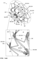
- FIGs. 12A-B , 13A-B , and 14A-B are schematic illustrations of an occlusion device 510 for occluding an LAA, in accordance with an application of the present invention.
- Occlusion device 510 is for use with a delivery system, such as delivery system 20, described hereinabove with reference to Figs. 1-4C ; delivery system 120, described hereinabove with reference to Figs. 6-7C ; delivery system 220, described hereinabove with reference to Figs. 8-9B ; or delivery system 320, described hereinabove with reference to Figs. 10-11 , mutatis mutandis.
- a delivery system such as delivery system 20, described hereinabove with reference to Figs. 1-4C ; delivery system 120, described hereinabove with reference to Figs. 6-7C ; delivery system 220, described hereinabove with reference to Figs. 8-9B ; or delivery system 320, described hereinabove with reference to Figs
- occlusion device 510 is similar to occlusion device 10, described hereinabove with reference to Figs. 1-5 , and may implement any of the features thereof, mutatis mutandis. Like reference numerals refer to like parts. Alternatively or additionally, occlusion device 510 may optionally implement any of the features of occlusion device 110, described hereinabove with reference to Figs. 6 and 7A-C ; occlusion device 210, described hereinabove with reference to Figs. 8 and 9A-B ; occlusion device 310, described hereinabove with reference to Figs. 10 and 11 ; and/or occlusion device 410, described hereinabove with reference to Fig.
- occlusion device 510 may optionally comprise proximal LAA-orifice cover 70, such as shown in the figures.
- these other occlusion devices described herein may optionally implement any of the features of occlusion device 510, mutatis mutandis.
- Figs. 12A-B show occlusion device 510 after sheath 82, shown in Fig. 3A , has been proximally withdraw, thereby releasing occlusion device 510, and allowing proximal LAA-orifice cover 70 to transition to its radially-expanded state. This is similar to the state of deployment of occlusion device 10 shown in Fig. 3B . Balloon 30 remains in a non-inflated, elongate configuration at this stage of deployment.
- Figs. 13A-B show occlusion device 510 upon partial inflation of balloon chamber 32.
- Figs. 14A-B show occlusion device 510 upon final inflation of balloon chamber 32.
- Balloon chamber 32 can be inflated at different final inflation levels, depending on the extent of radial expansion necessary for the particular anatomy of the LAA.
- occlusion device 510 is configured to be radially expandable to a diameter of between 15 and 40 mm, e.g., between 20 and 35 mm, such as between 15 and 35 mm.
- Occlusion device 510 comprises connecting struts 580 fixed to distal end portion 36 of balloon 30 and to proximal end portion 38 of balloon 30.
- Struts 580 may implement any of the features of struts 80, described hereinabove, mutatis mutandis.
- First lateral portions 581A of struts 580 are arranged along a lateral surface of balloon 30.
- Second distal-end portions 581B of struts 580 are arranged on a distal surface of balloon 30.
- Third proximal-end portions 581C of struts 580 are arranged on a proximal surface of balloon 30.
- second distal-end portions 581B and third proximal-end portions 581C are generally straight.
- first lateral portions 581A are oriented parallel to a central longitudinal axis of occlusion device 510.
- distal interface portions 583A of struts 580 join first lateral portions 581A and second distal-end portions 581B, respectively, and/or proximal interface portions 583B join first lateral portions 581A and third proximal-end portions 581C, respectively.
- Occlusion device 510 is configured such that upon inflation of balloon chamber 32, distal interface portions 583A and proximal interface portions 583B are curved, such as shown in Figs. 13A-B and 14A-B . ( Figs. 12A-B shown balloon chamber 32 uninflated, Figs. 13A-B show balloon chamber 32 partially inflated, and Figs.
- distal interface portions 583A and/or proximal interface portions 583B have a serpentine (e.g., sinusoidal) shape, as shown.
- This serpentine shape causes distal interface portions 583A and/or proximal interface portions 583B to be more compliant than first lateral portions 581A, second distal-end portions 581B, and/or third proximal-end portions 581C.
- occlusion device 510 upon inflation and shortening of balloon 30, assumes a more cylindrical shape that it otherwise would.
- first lateral portions 581A of struts 580 are generally straight, which also contributes to the cylindrical shape of occlusion device 510.
- distal end portions 585A of struts 580 join second distal-end portions 581B of struts 580 to distal end portion 36 of balloon 30, respectively, and/or proximal end portions 585B of struts 580 join third proximal-end portions 581C of struts 580 to proximal end portion 38 of balloon 30, respectively.
- Occlusion device 510 is configured such that upon inflation of balloon chamber 32, distal end portions 585A and proximal end portions 585B are curved. ( Figs. 12A-B shown balloon chamber 32 uninflated, Figs. 13A-B show balloon chamber 32 partially inflated, and Figs.
- distal end portions 585A and/or proximal end portions 585B have a serpentine (e.g., sinusoidal) shape, as shown.
- This serpentine shape allows distal end portions 585A and/or proximal end portions 585B to elongate, thereby allowing occlusion device 510 to radially expand, such as to a diameter, for example, of between 15 and 40 mm, e.g., between 20 and 35 mm, such as between 15 and 35 mm.
- This serpentine shape also allows distal end portions 585A and/or proximal end portions 585B to selectively elongate, thereby accommodating expansion of balloon 30 to different extents in different radial directions.
- struts 580 are shaped so as to define a plurality of spikes 589 that extend from outer ends 599 (labeled in Figs. 12A and 14A ) of second distal-end portions 581B, respectively, and/or third proximal-end portions 581C, respectively.
- Spikes 589 are initially generally axially oriented, when balloon 30 is in a non-inflated, elongate configuration, as shown in Figs. 12A-B .
- Spikes 589 are configured to extend more radially upon inflation of balloon chamber 32 to serve as tissue-engaging barbs, as shown in Figs. 14A-B .
- the respective axes of spikes 589 may be parallel with or slightly angled with respect to axes of second distal-end portions 581B and third proximal-end portions 581C.
- distal interface portions 583A are shaped so as to define respective pairs of parallel serpentine (e.g., sinusoidal) struts 591A and 591B that define respective narrow elongate gaps 593 therebetween.
- spikes 589 When spikes 589 are initially generally axially oriented, as shown in Figs. 12A-B , the spikes are disposed in respective gaps 593.
- Respective tips 595 of spikes 589 are disposed near respective end surfaces 597 of gaps 593 at respective junctions between the parallel serpentine struts 591A and 591B, such that the respective tips 595 of spikes 589 are protected by respective end surfaces 597 until the spikes are radially deployed.
- proximal interface portions 583B and their corresponding spikes 589 may implement this feature.
- connecting struts 580 further include closed stent cells 587 that connect adjacent pairs of first lateral portions 581A.
- closed stent cells 587 that connect adjacent pairs of first lateral portions 581A.
- two or more closed stent cells 587 arranged in series connect the adjacent pairs of first lateral portions 581A (in the figures, exactly two closed stent cells 587 arranged in series are shown connecting the adjacent pairs of first lateral portions 581A); typically, no more than four closed stent cells 587 arranged in series, such as exactly two or three closed stent cells 587 arranged in series.
- connections by closed stent cells 587 may help laterally stabilize first lateral portions 581A upon inflation of balloon chamber 32, and may help constrain the shape of balloon 30 upon inflation of balloon chamber 32, by helping limit radial expansion of the balloon out of the stent struts.
- These connections by closed stent cells 587 may alternatively or additionally stabilize the implantation of occlusion device 510 by friction, by providing a sufficiently large contract surface with the walls of the LAA.
- a single series of two or more closed stent cells 587 connect adjacent pairs of first lateral portions 581A, as shown; alternatively, two or more series (e.g., exactly two series) of two or more closed stent cells 587 connect adjacent pairs of first lateral portions 581A (configuration not shown).
- an average width of the struts of first lateral portions 581A equals at least 200% of an average width of the struts of closed stent cells 587, such as at least 250%, 300%, or 400%.
- typically first lateral portions 581A are oriented parallel to a central longitudinal axis of occlusion device 510.
- the struts of closed stent cells 587 may have these thinner widths in order to allow expansion of the closed stent cells with the expansion of the balloon.
- closed stent cells 587 are shaped as respective rhombuses.
- Rhombuses can be radially compressed for delivery such that they predictably expand symmetrically, unlike many other stent shapes that tend to expand asymmetrically, such as S-shapes and serpentine shapes. Rhombuses also generally return to their original shape when plastically expanded for implantation after being plastically radially compressed for delivery.
- the rhombuses may be shaped as squares and/or diamonds at certain levels of radial compression and expansion.
Landscapes
- Health & Medical Sciences (AREA)
- Surgery (AREA)
- Life Sciences & Earth Sciences (AREA)
- Heart & Thoracic Surgery (AREA)
- Molecular Biology (AREA)
- Vascular Medicine (AREA)
- Engineering & Computer Science (AREA)
- Biomedical Technology (AREA)
- Reproductive Health (AREA)
- Medical Informatics (AREA)
- Nuclear Medicine, Radiotherapy & Molecular Imaging (AREA)
- Animal Behavior & Ethology (AREA)
- General Health & Medical Sciences (AREA)
- Public Health (AREA)
- Veterinary Medicine (AREA)
- Cardiology (AREA)
- Prostheses (AREA)
- Media Introduction/Drainage Providing Device (AREA)
- Surgical Instruments (AREA)
Description
- The present invention generally relates to an occlusion device for occluding a left atrial appendage.
- The left atrial appendage (LAA) is a cavity that presents in the left atrium of the heart. In patients with atrial fibrillation, the passage and steadiness of blood within this cavity can cause thrombus formation, which increases the risk of stroke. Percutaneous LAA occlusion is a therapy for the prevention of stroke in patients with atrial fibrillation. LAA occlusion is used as an alternative to, or in combination with, oral anticoagulant therapy. LAA occlusion has favorable clinical outcomes, but commercially-available devices are typically self-expandable, and not designed to adapt to the LAA anatomy, and thus sometimes result in complications or suboptimal outcomes. In these environments, some of the currently available occlusion devices are limited by the poor adaptability of the device to the defect (lack of conformability) and by a lack of intra-device sealing (due to the high-flow environment).
- Publication
EP 3 459 469 A1 discloses an occlusion device as defined in the preamble ofindependent claim 1. -
PCT Publication WO 2019/057950 to Maisano et al. describes an occluder device for occluding a cardiovascular defect or a gap between a medical device and adjacent body tissue, including a compliant balloon defining a fluid-tight balloon chamber and provided with a balloon channel forming a longitudinal passage from a proximal side to a distal side of the balloon; a tip element disposed at the distal side of the balloon, a base element disposed at the proximal side of the balloon, and connecting means comprising at least one connecting strut attached to the tip element and to the base element, the tip element and the base element each having a guide opening substantially coaxial to the balloon channel for slidingly receiving therein a guidewire for the device; elongated actuating means disposed longitudinally slidable in the balloon channel, releasably connectable to the tip element, and longitudinally slidable with respect to the base element; locking means for maintaining a predetermined distance between the tip element and the base element; and proximal connector means for releasably connecting the occluder device to correspondingly configured distal connector means of a catheter device. The balloon includes a fluid port for filling and unfilling a fluid into and from the balloon chamber. An occluder system comprises an occluder device and a catheter device cooperating therewith. -
US Patent 6,652,556 to VanTassel et al. describes apparatus for permanent placement across an ostium of a left atrial appendage in a patient, which includes a filtering membrane configured to extend across the ostium of the left atrial appendage. The filtering membrane has a permeable structure which allows blood to flow through but substantially inhibits thrombus from passing therethrough. The apparatus also includes a support structure comprising a plurality of fingers which are radially outwardly expandable with respect to a longitudinal axis to permanently engage the interior wall of the left atrial appendage. The filtering membrane is attached to the support structure extending across the ostium of the left atrial appendage. - The present invention concerns an occlusion device comprising the features defined in the
independent claim 1. Preferred embodiments are defined in the dependent claims. The present invention will be more fully understood from the following detailed description of embodiments thereof, taken together with the drawings, in which: -
-
Fig. 1 is a schematic illustration of an occlusion device for occluding a left atrial appendage (LAA), in accordance with an application of the present invention; -
Figs. 2A-B are schematic cross-sectional illustrations of the occlusion device ofFig. 1 and a distal portion of a delivery system, in accordance with an application of the present invention; -
Figs. 3A-F are schematic illustrations of steps of a method of deploying the occlusion device ofFig. 1 using the delivery system ofFig. 2 , in accordance with an application of the present invention; -
Figs. 4A-C are schematic cross-sectional views of a portion of the steps of the method shown inFigs. 3A-F , in accordance with an application of the present invention; -
Fig. 5 is a schematic illustration of the occlusion device ofFig. 1 implanted to occlude an LAA, in accordance with an application of the present invention; -
Fig. 6 is a schematic illustration of another occlusion device for occluding an LAA, in accordance with an application of the present invention; -
Figs. 7A-C are schematic cross-sectional illustrations of the occlusion device ofFig. 6 and a distal portion of a delivery system, in accordance with an application of the present invention; -
Fig. 7D is a schematic illustration of another occlusion device for occluding an LAA, in accordance with an application of the present invention; -
Fig. 8 is a schematic illustration of yet another occlusion device for occluding an LAA, in accordance with an application of the present invention; -
Figs. 9A-B are schematic cross-sectional illustrations of the occlusion device ofFig. 8 and a distal portion of a delivery system, in accordance with an application of the present invention; -
Fig. 10 is a schematic illustration of still another occlusion device for occluding an LAA, in accordance with an application of the present invention; -
Fig. 11 is a schematic cross-sectional illustration of the occlusion device ofFig. 10 and a distal portion of a delivery system, in accordance with an application of the present invention; -
Figs. 12A-B are schematic illustrations of another occlusion device for occluding an LAA, partially deployed, in accordance with an application of the present invention; -
Figs. 13A-B are schematic illustrations of the occlusion device ofFigs. 12A-B upon partial inflation of a balloon chamber thereof, in accordance with an application of the present invention; and -
Figs. 14A-B are schematic illustrations of the occlusion device ofFigs. 12A-B upon final inflation of a balloon chamber thereof, in accordance with an application of the present invention. -
Fig. 1 is a schematic illustration of anocclusion device 10 for occluding a left atrial appendage (LAA), in accordance with an application of the present invention.Occlusion device 10 is for use with adelivery system 20, which is described in more detail hereinbelow with reference toFigs. 3A-F .Delivery system 20 and the other delivery systems described herein are typically transcatheter delivery systems that enable percutaneous deployment of the occlusion devices. - Reference is also made to
Figs. 2A-B , which are schematic cross-sectional illustrations ofocclusion device 10 and a distal portion ofdelivery system 20, in accordance with an application of the present invention.Fig. 2A showsocclusion device 10 with alocking mechanism 40 thereof in an unlocked state andvalve 42 thereof in an open state, as described hereinbelow.Fig. 2B showsocclusion device 10 withlocking mechanism 40 in a locked state andvalve 42 in a closed state, as described hereinbelow. - For some applications,
occlusion device 10 comprises: - a
compliant balloon 30 defining a fluid-tight balloon chamber 32; - an
actuating shaft 34, which is (a) disposed at least partially withinballoon chamber 32, (b) connected to adistal end portion 36 ofballoon 30, and (c) longitudinally moveable with respect to aproximal end portion 38 ofballoon 30 so as to set a distance between distal andproximal end portions balloon 30; -
locking mechanism 40, which is configured to assume locked and unlocked states, as shown inFig. 2B and 2A , respectively; and - a
valve 42. -
Occlusion device 10 is configured such that proximally longitudinally moving actuatingshaft 34 expandsballoon 30 in a radial or a lateral direction by shortening the distance between distal andproximal end portions balloon 30 to a desired distance. - Locking
mechanism 40 is configured, when in the locked state, to maintain, betweendistal end portion 36 ofballoon 30 andproximal end portion 38 ofballoon 30, the distance set usingactuating shaft 34. - For some applications,
occlusion device 10 is shaped so as to define afluid flow path 44 along (e.g., alongside, as shown) a portion of actuatingshaft 34.Valve 42 is configured to selectively: - allow fluid flow between
fluid flow path 44 andballoon chamber 32 whenvalve 42 is in the open state, as shown inFig. 2A , or - block fluid flow between
fluid flow path 44 andballoon chamber 32 whenvalve 42 is in the closed state, as shown inFig. 2B . - For some applications,
occlusion device 10 is configured such that reduction of the distance, by proximal longitudinal movement of actuating shaft 34: - to a first predetermined distance between distal and
proximal end portions balloon 30 automatically transitionsvalve 42 from the open state to the closed state, as shown in the transition fromFig. 2A to Fig. 2B , and - to a second predetermined distance between distal and
proximal end portions balloon 30 automatically transitions lockingmechanism 40 from the unlocked state to the locked state, as also shown in the transition fromFig. 2A to Fig. 2B . - For some applications, the first predetermined distance does not equal the second predetermined distance. For example, the first predetermined distance may be less than the second predetermined distance, such that the proximal longitudinal movement of actuating
shaft 34 first automatically transitionsvalve 42 from the open state to the closed state and subsequently automatically transitions lockingmechanism 40 from the unlocked state to the locked state. Alternatively, the first predetermined distance may be greater than the second predetermined distance, such that this sequence is reversed. - Further alternatively, for some applications, the first predetermined distance equals the second predetermined distance, such that the proximal longitudinal movement of actuating
shaft 34 simultaneously automatically transitionsvalve 42 from the open state to the closed state and automatically transitions lockingmechanism 40 from the unlocked state to the locked state. - For some applications, in order to cause the above-mentioned proximal longitudinal movement of actuating
shaft 34,delivery system 20 comprises apull shaft 46, which is releasably coupled a proximal end portion of actuatingshaft 34. For example, a distal portion ofpull shaft 46 may comprise a pull-shaft coupling 48, which may, for example, be shaped so as to define a thread that removably engages a corresponding thread defined by the proximal end portion of actuatingshaft 34. Rotation ofpull shaft 46 disengagesshaft coupling 48 from the corresponding thread defined by the proximal end portion of actuatingshaft 34. - Typically,
occlusion device 10 is configured to be releasably connected todelivery system 20. For some applications,occlusion device 10 is configured such thatfluid flow path 44 is coupled in fluid communication withdelivery system 20 whenocclusion device 10 is releasably connected todelivery system 20, such as shown inFigs. 2A-B . - For some applications, actuating
shaft 34 is shaped so as to define, at least in part, adistal tip 50 disposed atdistal end portion 36 ofballoon 30, as shown inFigs. 1 and2A-B . - For some other applications,
occlusion device 10 further comprises a distal tip disposed atdistal end portion 36 ofballoon 30, and actuatingshaft 34 is connected to the distal tip (configuration not shown). - Alternatively or additionally, for some applications,
occlusion device 10 further comprises a proximal base disposed atproximal end portion 38 ofballoon 30, and actuatingshaft 34 is moveable (e.g., longitudinally or rotationally) with respect to the proximal base (configuration not shown). - For some applications,
valve 42 is disposed along actuatingshaft 34, such as shown inFigs. 2A-B . - For some applications,
occlusion device 10 further comprises aproximal tube 52, which is axially fixed with respect toproximal end portion 38 ofballoon 30. Actuatingshaft 34 is slidably disposed partially withinproximal tube 52, e.g., so as to indirectly connect actuatingshaft 34 toproximal end portion 38 viaproximal tube 52. For some of these applications,occlusion device 10 is shaped so as to definefluid flow path 44 along the portion of actuatingshaft 34, radially between an external surface of actuatingshaft 34 and an internal surface ofproximal tube 52, such as shown inFigs. 2A-B . Optionally,valve 42 is disposed along actuatingshaft 34. - For some applications,
valve 42 comprises aseal 54 around at least a portion of (e.g., entirely around) the external surface of actuatingshaft 34.Valve 42 is configured to assume (a) the open state whenseal 54 is disposed at one or more firstaxial positions 56A with respect to proximal tube 52 (one such first axial position is shown inFig. 2A ), and (b) the closed state whenseal 54 is disposed at one or more secondaxial positions 56B with respect to proximal tube 52 (one such second axial position is shown inFig. 2B ). The one or more secondaxial positions 56B are proximal to the one or more firstaxial positions 56A. For example, seal 54 may comprise an O-ring, as shown inFigs. 2A-B , e.g., a single O-ring or a series of O-rings. Optionally, one or moreadditional seals 19, e.g., one or more O-rings, are provided to provide further stabilization an alignment of the distal tube inside the proximal tube by friction. - For some applications,
seal 54, actuatingshaft 34, andproximal tube 52 are arranged such thatseal 54 blocks fluid flow out of adistal end 58 ofproximal tube 52, at least whenseal 54 is disposed at the one or more firstaxial positions 56A with respect toproximal tube 52, such as shown inFig. 2A . Alternatively or additionally, friction betweenseal 54 and the inner surface ofproximal tube 52 increases structural stability, and/or enables stepwise inflation/implantation. - For some applications, a wall of
proximal tube 52 is shaped so as to define one ormore tabs 60 through the wall. The one ormore tabs 60 are biased to flex radially inward. Whenvalve 42 is in the open state, as shown inFig. 2A ,fluid flow path 44 passes through the wall between respective proximal ends 62 of the one ormore tabs 60 and anon-tabbed portion 64 of the wall axially adjacent the one ormore tabs 60, such as proximal to the one ormore tabs 60, as shown. - For some applications, the external surface of actuating
shaft 34 is shaped so as to define one ormore protrusions 66 around at least a portion of (e.g., entirely around) actuatingshaft 34. Proximal ends 62 of the one ormore tabs 60 are shaped so as to prevent distal movement of the one ormore protrusions 66 when the one ormore protrusions 66 are disposed proximal to the proximal ends 62 of the one ormore tabs 60, such as shown inFig. 2B , thereby causinglocking mechanism 40 to assume the locked state. - For some applications,
occlusion device 10 further comprises a proximal LAA-orifice cover 70, which: - is fixed to
proximal tube 52 radially surroundingproximal tube 52, - is configured to assume a radially-compressed state, such as shown in
Fig. 3A , described hereinbelow, and a radially-expanded state, such as shown inFigs. 1 and2A-B , - comprises
frame 72 and a covering 74 fixed to frame 72, - when in the radially-expanded state, is generally orthogonal to
proximal tube 52 and has a greatest dimension, measured perpendicular toproximal tube 52, of at least 10 mm (e.g., at least 20 mm), no more than 50 mm (e.g., no more than 30 mm), and/or between 10 and 50 mm (e.g., between 20 and 30 mm), and - is typically indirectly connected to balloon 30 via
proximal tube 52 and is not directly connected toballoon 30. - This indirect connection of proximal LAA-
orifice cover 70 to balloon 30 generally prevents an anodic reaction between the typically super-elastic (e.g., Nitinol) material offrame 72 of proximal LAA-orifice cover 70 and the typically plastically deformable (e.g., stainless steel) material ofstruts 80, described hereinbelow. Such a reaction might have occurred if the two elements were instead welded or otherwise bonded together in contact with each other. (Connection of the elements via an independent and passive element, such as an internal tube or shaft, also does not cause such a reaction.) Alternatively, proximal LAA-orifice cover 70 is directly connected to balloon 30, such as ifframe 72 comprises a different plastically-deformable material, such as titanium. - For some applications,
occlusion device 10 further comprises orifice-support stent 290, described hereinbelow with reference toFigs. 8 and9A-B . - For some applications, actuating
shaft 34 is shaped so as to define aguidewire lumen 76 for slidingly receiving therein a guidewire and/or passage of liquid injected under pressure, such as contrast media injected from the proximal handle of the delivery tool to the distal end of the occlusion device. Alternatively, for other applications, actuatingshaft 34 is not shaped so as to define a guidewire lumen. - For some applications,
compliant balloon 30 comprises a compliant material selected from the group consisting of polycaprolactone (PCL), polyglycolic acid (PGA), polylactic acid (PLA), and polydioxanone (PDO or PDS), silicone, polyurethane, polytetrafluoroethylene (PTFE), polymethylmethacrylate, polyether ether ketone (PEEK), polyvinyl chloride, polyethylene terephthalate, nylon, polyamide, polyamide, and polyether block amide (PEBA). - For some applications,
balloon 30 has an average wall thickness of between 100 and 5000 microns. Alternatively or additionally, for some applications,balloon 30 has, at a thinnest portion of a wall ofballoon 30, a thinnest wall thickness of between 20 and 500 microns. - For some applications,
occlusion device 10 further comprises connectingstruts 80 fixed todistal end portion 36 ofballoon 30 and toproximal end portion 38 ofballoon 30.Struts 80 may be disposed insideballoon 30,outside balloon 30, or some inside and someoutside balloon 30. For some applications, struts 80 are arranged as a frame. For some applications, struts 80 are arranged in a cage-like arrangement. Typically, struts 80 comprise a plastically-deformable material, such as stainless steel or titanium. Typically, struts 80help shape balloon 30 as the balloon chamber is inflated and/or the balloon is shortened. - Typically,
occlusion device 10 is configured such that inflation ofballoon chamber 32 plastically deforms connectingstruts 80. For some applications,occlusion device 10 is configured such that shortening ofballoon 30 plastically deforms connectingstruts 80. - For some applications, struts 80 are configured such that inflation of
balloon chamber 32 primarily causes radial deformation ofstruts 80, rather than deformation of the struts in a distal or proximal direction. To this end, first lateral portions 81A ofstruts 80 arranged along a lateral surface ofballoon 30 may be more compliant than second end portions 81B ofstruts 80 arranged on a distal surface ofballoon 30 and/or on a proximal surface ofballoon 30. For example, first lateral portions 81A may be thinner than second end portions 81B, as shown inFig. 1 , and/or first lateral portions 81A may be shaped to be more compliant, e.g., have a serpentine (e.g., sinusoidal) shape, as shown. Typically, first lateral portions 81A are oriented parallel to a central longitudinal axis ofocclusion device 10. - Reference is now made to
Figs. 3A-F , which are schematic illustrations of steps of a method of deployingocclusion device 10 usingdelivery system 20, in accordance with an application of the present invention. - Reference is also made to
Figs. 4A-C , which are schematic cross-sectional views of a portion of the steps of the method shown inFigs. 3A-F , in accordance with an application of the present invention. -
Fig. 3A schematically showsocclusion device 10 releasably disposed in a radially-compressed state within asheath 82 ofdelivery system 20. Typically, a greatest distance betweenproximal end portion 38 ofballoon 30 anddistal end portion 36 ofballoon 30 is at least 8 mm (e.g., at least 15 mm), no more than 80 mm (e.g. no more than 60 mm), and/or between 8 and 80 mm (e.g., between 15 and 60 mm), whenocclusion device 10 is in this radially-compressed state. - For some applications,
occlusion device 10 comprises aproximal connector 84 that is configured to releasably connectocclusion device 10 to a correspondingly configureddistal connector 86 ofdelivery system 20. - For some applications,
distal connector 86 comprises one or more legs that engage one or more respective coupling sites (e.g., slots) ofproximal connector 84, such as perhaps best seen inFigs. 4A-C . For example, the legs may be configured to biased radially outward when in an unconstrained, resting state, and may be held radially inward engaging the coupling sites ofproximal connector 84, such as byimplant catheter 88, as shown inFig. 4A . Proximal withdrawal ofimplant catheter 88 with respect toocclusion device 10 release the legs, as shown inFig. 4B . - Alternatively,
proximal connector 84 is shaped so as to define a thread (configuration not shown). - For some applications,
delivery system 20 comprises animplant catheter 88 that is connected to an operating handle (not shown).Implant catheter 88 comprises (a) a longitudinal passageway for a guidewire, (b)distal connector 86 for releasably connectingimplant catheter 88 to correspondingly configuredproximal connector 84 ofocclusion device 10, and (c) an inflation tube channel releasably connectable tofluid flow path 44 ofocclusion device 10. The longitudinal passageway may alternatively or additionally be used to inject contrast media from the handle to a distal opening of the inflation tube channel distally to the balloon. -
Fig. 3B showsocclusion device 10 aftersheath 82 has been proximally withdrawn, thereby releasingocclusion device 10.Fig. 3B also shows proximal LAA-orifice cover 70 in its radially-expanded state. Typically,frame 72 of proximal LAA-orifice cover 70 comprises a shape-memory memory, e.g., a super-elastic metal, which causes cover 70 to automatically transition to the radially-expanded state upon release fromsheath 82.Balloon 30 remains in a non-inflated, elongate configuration at this stage of deployment. - Typically, a healthcare worker places the distal end of
occlusion device 10 into the LAA, using delivery system navigation. - As shown in
Figs. 3C-D , the healthcare worker inflatesballoon chamber 32.Fig. 3C showsocclusion device 10 upon partial inflation ofballoon chamber 32, whileFig. 3D showsocclusion device 10 upon complete inflation ofballoon chamber 32.Balloon 30 may be inflated by fillingballoon chamber 32 with any fluid, including but not limited to saline solution (optionally comprising a contrast medium), blood (e.g., autologous blood), foam, and/or a glue (e.g., a gel, a liquid polymer that can change its proprieties to become rigid, or a hydrogel that remains a gel or self-cures at body temperature). - For some applications, struts 80 are shaped so as to define a plurality of
spikes 89 that are initially generally axially oriented, as shown inFig. 3C , and are configured to extend more radially upon expansion ofballoon 30 to serve as tissue-engaging barbs, as shown inFig. 3D . -
Figs. 3E and4A showocclusion device 10 after (a)valve 42 has transitioned from the open state to the closed state, (b) actuatingshaft 34 has been proximally longitudinally moved to expandballoon 30 in a radial or a lateral direction by shortening the distance between distal andproximal end portions balloon 30 to a desired distance, and (c)locking mechanism 40 has transitioned from the unlocked state to the locked state, as described hereinabove with reference toFigs. 2A-B . Typically, afterballoon 30 has been finally filled, actuatingshaft 34 is proximally longitudinally moved to expandballoon 30 in a radial or a lateral direction by shortening the distance between distal andproximal end portions balloon 30 to a desired distance.Proximal connector 84 ofocclusion device 10 is still releasably connected to correspondingly configureddistal connector 86 ofdelivery system 20. -
Figs. 3F and4B-C show occlusion device 10 afterproximal connector 84 ofocclusion device 10 has been released fromdistal connector 86 ofdelivery system 20. -
Fig. 4C also showsocclusion device 10 afterpull shaft 46 has been decoupled from the proximal end portion of actuatingshaft 34, such as by rotatingpull shaft 46 to unscrew it, as described hereinabove. - Reference is now made to
Fig. 5 , which is a schematic illustration ofocclusion device 10 implanted to occlude anLAA 100, in accordance with an application of the present invention. As can be seen,balloon 30 is disposed withinLAA 100, and proximal LAA-orifice cover 70 is disposed in aleft atrium 102 outsideLAA 100, against the atrial wall surrounding the orifice ofLAA 100, thereby creating a continuum with the atrium at the LAA level. Typically, proximal LAA-orifice cover 70 protrudes only minimally because of its relatively flat shape, so as not to interfere with blood flow and not to cause thrombosis. Typically, struts 80 provide most of the anchoring ofocclusion device 10, andballoon 30 provides most of the sealing of the LAA. In addition, in configurations in which covering 74 of proximal LAA-orifice cover 70 is blood-impermeable, proximal LAA-orifice cover 70 provides additional sealing of the LAA, primarily to inhibit creation of thrombi on the balloon surface at the orifice level. - For some applications, proximal LAA-
orifice cover 70 is asymmetric aboutproximal tube 52, e.g., elliptical or with a radius greater in one direction than in the perpendicular direction. - For some applications, proximal LAA-
orifice cover 70 is configured to have an adjustable greatest dimension measured perpendicular toproximal tube 52. For example, rotation of a proximal LAA-orifice cover 70 adjustment mechanism may adjust the greatest dimension. - For some applications, covering 74 of proximal LAA-
orifice cover 70 is blood-permeable, so as to serve as filter for the passage of blood in and out of the LAA. For other applications, covering 74 is not blood-permeable, so as to create a secondary sealing of the LAA in addition to the sealing provided byballoon 30. - For some applications, proximal LAA-
orifice cover 70 is bioresorbable and/or drug-eluting. - Reference is now made to
Fig. 6 , which is a schematic illustration of anocclusion device 110 for occluding an LAA, in accordance with an application of the present invention.Occlusion device 110 is for use with adelivery system 120. Other than as described hereinbelow,occlusion device 110 is similar toocclusion device 10, described hereinabove with reference toFigs. 1-5 , and may implement any of the features thereof, mutatis mutandis. Similarly, other than as described hereinbelow,delivery system 120 is similar todelivery system 20, described hereinabove with reference toFigs. 1-5 , and may implement any of the features thereof, mutatis mutandis. Like reference numerals refer to like parts. - Reference is also made to
Figs. 7A-C , which are schematic cross-sectional illustrations ofocclusion device 110 and a distal portion ofdelivery system 120, in accordance with an application of the present invention.Figs. 7A-B show occlusion device 110 connected todelivery system 120, withvalve 142 ofocclusion device 110 in an open state, as described hereinbelow.Fig. 7A showsocclusion device 110 withballoon 130 thereof in an elongated state, andFigs. 7B-C show occlusion device 110 withballoon 130 in a shortened state.Fig. 7C showsocclusion device 110 connected todelivery system 120, withvalve 142 in a closed state. - For some applications,
occlusion device 110 comprises: - a
compliant balloon 130 defining a fluid-tight balloon chamber 132;balloon 130 may have any of the properties ofballoon 30, described hereinabove with reference toFigs. 1-5 ; - an
actuating shaft 134, which is (a) disposed at least partially withinballoon chamber 132, (b) connected to adistal end portion 136 ofballoon 130, and (c) longitudinally moveable with respect to aproximal end portion 138 ofballoon 130 so as to set a distance between distal andproximal end portions balloon 130; and - a
valve 142, comprising anelastomer sleeve 143 that surrounds a portion ofactuating shaft 134. -
Occlusion device 110 is shaped so as to define afluid flow path 144 having one or more fluid-flow-path openings 145 toballoon chamber 132. Typically,occlusion device 110 is configured such thatfluid flow path 144 is coupled in fluid communication withdelivery system 120 whenocclusion device 110 is releasably connected todelivery system 120. - For example,
elastomer sleeve 143 may comprise silicone. -
Elastomer sleeve 143 is configured to have a resting state in which the sleeve covers and seals the one or more fluid-flow-path openings 145, such thatvalve 142 is in a closed state, as shown inFig. 7C . -
Delivery system 120 is configured to be releasably connected toocclusion device 110.Delivery system 120 comprises a valve-opening prop 147, which is configured: - when in a propping position, such as shown in
Figs. 6 and 7A-B , to prop open anddeform elastomer sleeve 143 such thatelastomer sleeve 143 does not seal the one or more fluid-flow-path openings 145 andvalve 142 is in an open state, and - when in a non-propping position, such as shown in
Fig. 7C , not to propopen elastomer sleeve 143, such that elastomer sleeve assumes the resting state andvalve 142 is in the closed state. - This configuration enables separate control of shortening of
balloon 130 and closing ofvalve 142. Alternatively, valve-opening prop 147 (e.g.,tubular portion 151 thereof, described below) is fixed to pullshaft 46. - For some applications, valve-
opening prop 147 comprises one ormore tabs 149 that extend radially outward from an axis ofelastomer sleeve 143, so as to propopen elastomer sleeve 143. - For some applications, valve-
opening prop 147 is configured such that axial sliding thereof with respect to elastomer sleeve 143 (e.g., in a proximal direction) transitions valve-opening prop 147 from the propping position to the non-propping position, as shown in the transition betweenFig. 7B andFig. 7C . - For some applications,
occlusion device 110 further comprises aproximal tube 152, which is axially fixed with respect toproximal end portion 138 ofballoon 130. For some applications, actuatingshaft 134 is slidably disposed partially withinproximal tube 152. - For some applications, a seal, such as an O-ring (as shown), is provided, and friction between the seal and the inner surface of a
proximal tube 152 increases structural stability. Alternatively or additionally, the O-ring, upon completion of the shortening of the balloon, is disposed proximal to the one or more fluid-flow-path openings 145 and blocks additional fluid from passing through the one or more fluid-flow-path openings 145 andelastomer sleeve 143. - For some applications, valve-
opening prop 147 comprises atubular portion 151, which is disposed at least partially withinproximal tube 152. For some of these applications, valve-opening prop 147 comprises the one ormore tabs 149, which extend (a) axially away from tubular portion 151 (e.g., in a distal direction) and (b) radially outward fromproximal tube 152, so as to propopen elastomer sleeve 143. For some applications, the one ormore tabs 149 pass through at least a portion of the one or more fluid-flow-path openings 145 when valve-opening prop 147 is in the propping position, such as shown inFigs. 6 and7A-B . Alternatively, for some applications,proximal tube 152 is shaped so as to define one or more access openings through a wall ofproximal tube 152, and the one ormore tabs 149 pass through the one or more access openings at least when valve-opening prop 147 is in the propping position (configuration not shown). - For some applications,
occlusion device 110 further comprises proximal LAA-orifice cover 70, which is fixed toproximal tube 152 radially surroundingproximal tube 152. Proximal LAA-orifice cover 70 may implement any of the techniques described hereinabove and/or hereinbelow. For some of these applications,occlusion device 110 further comprises an orifice-support stent 290, described hereinbelow with reference toFigs. 8 and9A-B . - For some applications,
occlusion device 110 further comprises a locking mechanism, which is configured to assume locked and unlocked states, and which is configured, when in the locked state, to maintain, betweendistal end portion 136 ofballoon 130 andproximal end portion 138 ofballoon 130, the distance set usingactuating shaft 134. The locking mechanism may implement any of the locking mechanisms described herein, mutatis mutandis. - For some applications, actuating
shaft 134 is shaped so as to define, at least in part, adistal tip 150 disposed atdistal end portion 136 ofballoon 130. - For some applications,
occlusion device 110 further comprises connectingstruts 180 fixed todistal end portion 136 ofballoon 130 and toproximal end portion 138 ofballoon 130. Typically,occlusion device 110 is configured such that inflation ofballoon chamber 132 plastically deforms connectingstruts 180. For some applications,occlusion device 110 is configured such that shortening ofballoon 130 plastically deforms connectingstruts 180. - For some applications,
delivery system 120 further comprisingimplant catheter 88, such as described hereinabove with reference toFigs. 1-5 . - Reference is now made to
Fig. 7D , which is a schematic illustration of anocclusion device 410 for occluding an LAA, in accordance with an application of the present invention. For clarity of illustration, a balloon is not shown connected tostruts 180 inFig. 7D , even though it is an actual element of the occlusion device.Occlusion device 410 is for use with a delivery system. Other than as described hereinbelow,occlusion device 410 is similar toocclusion device 110, described hereinabove with reference toFigs. 6 and7A-C , and may implement any of the features thereof, mutatis mutandis. Like reference numerals refer to like parts. Similarly, other than as described hereinbelow, the delivery system is similar todelivery system 20, described hereinabove with reference toFigs. 1-5 , and may implement any of the features thereof, mutatis mutandis. -
Occlusion device 410 comprises avalve 442, comprisingelastomer sleeve 143 that surrounds a portion ofactuating shaft 134.Elastomer sleeve 143 is configured to have a resting state in which the sleeve covers and seals the one or more fluid-flow-path openings 145, such that the valve is in a closed state (not shown inFig. 7D , but similar to the state shown inFig. 7C for occlusion device 110). - Unlike
delivery system 120 ofocclusion device 110, the delivery system of the present configuration does not comprise valve-opening prop 147. Instead, the delivery system comprises one ormore guidewires 447, which: - when in a propping position, such as shown in
Fig. 7D , prop open anddeform elastomer sleeve 143 such thatelastomer sleeve 143 does not seal the one or more fluid-flow-path openings 145 andvalve 442 is in an open state, and - when in a non-propping position (not shown in
Fig. 7D , but similar to the state shown inFig. 7C for occlusion device 110), do not propopen elastomer sleeve 143, such that elastomer sleeve assumes the resting state andvalve 442 is in the closed state. - For some applications, the one or
more guidewires 447 pass through at least a portion of the one or more fluid-flow-path openings 145 when the one or more guidewires are in the propping position. - Reference is now made to
Fig. 8 , which is a schematic illustration of anocclusion device 210 for occluding an LAA, in accordance with an application of the present invention.Occlusion device 210 is for use with adelivery system 220. Like reference numerals refer to like parts. - Reference is also made to
Figs. 9A-B , which are schematic cross-sectional illustrations ofocclusion device 210 and a distal portion ofdelivery system 220, in accordance with an application of the present invention.Fig. 9A-B show occlusion device 210 connected todelivery system 220.Fig. 9A showsocclusion device 210 withballoon 230 thereof in an elongated state, andFig. 9B showsocclusion device 210 withballoon 230 in a shortened state. -
Occlusion device 210 comprises: - a
compliant balloon 230 defining a fluid-tight balloon chamber 232;balloon 230 may have any of the properties ofballoon 30, described hereinabove with reference toFigs. 1-5 ; - an
actuating shaft 234, which is (a) disposed at least partially withinballoon chamber 232, (b) connected to adistal end portion 236 ofballoon 230, and (c) longitudinally moveable with respect to aproximal end portion 238 ofballoon 230 so as to set a distance between distal andproximal end portions balloon 230; and - a
valve 242, which, as mentioned above, may implement any of the features of the valves described herein. -
Occlusion device 210 further comprises proximal LAA-orifice cover 70, which (a) is configured to assume a radially-compressed state and a radially-expanded state, (b) comprisesframe 72 and covering 74 fixed to frame 72, and (c) when in the radially-expanded state, is generally orthogonal to actuatingshaft 234 and has a greatest dimension, measured perpendicular to actuatingshaft 234, of at least 10 mm (e.g., at least 20 mm), no more than 50 mm (e.g., no more than 30 mm), and/or between 10 and 50 mm (e.g., between 20 and 30 mm). -
Occlusion device 210 still further comprises an orifice-support stent 290, which is configured to enhance support at the orifice of the LAA. Orifice-support stent 290 is configured to be positioned at least partially within the LAA, such as entirely within the LAA. Orifice-support stent 290 is: - fixed to and extends distally from proximal LAA-
orifice cover 70, - configured to assume a radially-compressed state (not shown) and a radially-expanded state (as shown in
Figs. 8 and9A-B ), and - generally cylindrical when in the radially-expanded state.
- As used in the present application, including in the claims and the Inventive Concepts, the phrase "generally cylindrical" is not limited to generally circularly cylindrical, and also includes within its scope other generally cylindrical shapes, such as generally elliptically cylindrical.
- For some applications, orifice-
support stent 290, when in the radially-expanded state, has (i) a greatest dimension, measured perpendicular to actuatingshaft 234, of at least 8 mm, no more than 50 mm, and/or between 8 and 50 mm, and/or (ii) an axial length of at least 4 mm (e.g. at least 5 mm), no more than 30 mm, and/or between 4 and 30 mm. - For some applications, orifice-
support stent 290 is not fixed to balloon 230, such that a shape ofballoon 230 can change independently of a shape of orifice-support stent 290. Alternatively or additionally, lack of direct physical contact between orifice-support stent 290 and connectingstruts 280 ofocclusion device 210 prevents an anodic reaction between the typically super-elastic (e.g., Nitinol) material ofstruts 280 and the typically plastically deformable (e.g., stainless steel) material of orifice-support stent 290. Such a reaction might have occurred if the two elements were instead welded or otherwise bonded together in contact with each other. (Connection of the elements via an independent and passive element, such as an internal tube or shaft, also does not cause such a reaction.) - For some applications, orifice-
support stent 290 comprises a super-elastic or plastically-deformable metal. - Typically,
occlusion device 210 is configured such that inflation ofballoon chamber 232 transitions orifice-support stent 290 from its radially-compressed state to its radially-expanded state. For some applications, because orifice-support stent 290 comprises a super-elastic metal, such as Nitinol, the stent, when crimped, will have a minimum diameter given by the thickness of its wall struts. When released, the stent tends to transition to its released diameter, which is higher than the crimped diameter. In configurations in whichballoon 230 is inflated within the stent, the stent will over-stretch, and its diameter will be greater than its released diameter, to an extent that depends upon the design and ability of over-dilatation of the stent struts. - For some applications,
occlusion device 210 further comprises aproximal tube 252, which is axially fixed with respect toproximal end portion 238 ofballoon 230. For these applications, proximal LAA-orifice cover 70 is fixed toproximal tube 252 radially surroundingproximal tube 252, and is indirectly connected to balloon 230 viaproximal tube 252 and is not directly connected toballoon 230. - Reference is now made to
Fig. 10 , which is a schematic illustration of anocclusion device 310 for occluding an LAA, in accordance with an application of the present invention.Occlusion device 310 is for use with adelivery system 320. Other than as described hereinbelow,occlusion device 310 is similar toocclusion device 10, described hereinabove with reference toFigs. 1-5 , and may implement any of the features thereof, mutatis mutandis. Similarly, other than as described hereinbelow,delivery system 320 is similar todelivery system 20, described hereinabove with reference toFigs. 1-5 , and may implement any of the features thereof, mutatis mutandis. Like reference numerals refer to like parts. - Reference is also made to
Fig. 11 , which is a schematic cross-sectional illustration ofocclusion device 310 and a distal portion ofdelivery system 320, in accordance with an application of the present invention. BothFig. 10 and Fig. 11 show occlusion device 310 connected todelivery system 320.Fig. 10 showsocclusion device 310 withballoon 330 thereof in an elongated state, andFig. 11 showsocclusion device 310 withballoon 330 in a shortened state, as described hereinbelow. -
Occlusion device 310 comprises: - a
compliant balloon 330 defining a fluid-tight balloon chamber 332;balloon 330 may have any of the properties ofballoon 30, described hereinabove with reference toFigs. 1-5 ; - a
proximal tube 352, which is axially fixed with respect to aproximal end portion 338 ofballoon 330; - a
spring 353; and - a
valve 342, which may implement any of the features of the valves described herein. -
Spring 353 is (a) disposed at least partially withinballoon chamber 232, (b) connected (directly or indirectly, such as via a tube) to adistal end portion 336 ofballoon 330 andproximal tube 352, and (c) has a relaxed length, as shown inFig. 11 . Whenspring 353 has the relaxed length,distal end portion 336 ofballoon 330 is at a relaxed distance fromproximal end portion 338 ofballoon 330, as shown inFig. 11 . -
Delivery system 320 is configured to be releasably connected toocclusion device 310.Delivery system 320 comprises astylet 355, which is removably disposed throughproximal tube 352 and withinspring 353.Occlusion device 310 is configured such that a degree of distal advancement ofstylet 355 withinspring 353 sets a tensed length ofspring 353, which in turn sets a tensed distance between distal andproximal end portions balloon 330, the tensed distance greater than the relaxed distance. One possible tensed distance is shown inFig. 10 . - Typically, during deployment of
occlusion device 310 in the LAA,occlusion device 310 is advanced into the LAA withspring 353 in the elongated tensed state.Balloon chamber 332 is typically inflated whilespring 353 is in the elongated tensed state, such as shown inFig. 10 , andvalve 342 is transitioned to the closed state, such as using techniques described herein. Thereafter,stylet 355 is partially proximally withdrawn, allowingspring 353 to shorten to its resting state, as shown inFig. 11 . - For some applications, a distal end portion of
stylet 355 is releasably connected to an occlusion-device connector 357 ofocclusion device 310, which is connected todistal end portion 336 ofballoon 330. (Even thoughstylet 355 would generally remain in place even if not connected toocclusion device 310, if not thus connectedstylet 355 might become disengaged from the center ofspring 353 and become entangled withspring 353 during maneuvering ofocclusion device 310 and inflation ofballoon 330 during deployment.) For these applications,stylet 355 is disconnected from occlusion-device connector 357 afterspring 353 has been allowed to shorten. For example, the end portion ofstylet 355 and occlusion-device connector 357 may define respective threads. - Optionally,
stylet 355 is flexible, e.g., highly flexible, to accommodate variations in LAA anatomy, including curvature of the LAA. - Reference is now made to
Figs. 12A-B ,13A-B , and14A-B , which are schematic illustrations of anocclusion device 510 for occluding an LAA, in accordance with an application of the present invention.Occlusion device 510 is for use with a delivery system, such asdelivery system 20, described hereinabove with reference toFigs. 1-4C ;delivery system 120, described hereinabove with reference toFigs. 6-7C ;delivery system 220, described hereinabove with reference toFigs. 8-9B ; ordelivery system 320, described hereinabove with reference toFigs. 10-11 , mutatis mutandis. Other than as described hereinbelow,occlusion device 510 is similar toocclusion device 10, described hereinabove with reference toFigs. 1-5 , and may implement any of the features thereof, mutatis mutandis. Like reference numerals refer to like parts. Alternatively or additionally,occlusion device 510 may optionally implement any of the features ofocclusion device 110, described hereinabove with reference toFigs. 6 and7A-C ;occlusion device 210, described hereinabove with reference toFigs. 8 and9A-B ;occlusion device 310, described hereinabove with reference toFigs. 10 and 11 ; and/orocclusion device 410, described hereinabove with reference toFig. 7D , mutatis mutandis. By way of example and not limitation,occlusion device 510 may optionally comprise proximal LAA-orifice cover 70, such as shown in the figures. Similarly, these other occlusion devices described herein may optionally implement any of the features ofocclusion device 510, mutatis mutandis. -
Figs. 12A-B show occlusion device 510 aftersheath 82, shown inFig. 3A , has been proximally withdraw, thereby releasingocclusion device 510, and allowing proximal LAA-orifice cover 70 to transition to its radially-expanded state. This is similar to the state of deployment ofocclusion device 10 shown inFig. 3B .Balloon 30 remains in a non-inflated, elongate configuration at this stage of deployment. -
Figs. 13A-B show occlusion device 510 upon partial inflation ofballoon chamber 32. -
Figs. 14A-B show occlusion device 510 upon final inflation ofballoon chamber 32.Balloon chamber 32 can be inflated at different final inflation levels, depending on the extent of radial expansion necessary for the particular anatomy of the LAA. Typically,occlusion device 510 is configured to be radially expandable to a diameter of between 15 and 40 mm, e.g., between 20 and 35 mm, such as between 15 and 35 mm. -
Occlusion device 510 comprises connecting struts 580 fixed todistal end portion 36 ofballoon 30 and toproximal end portion 38 ofballoon 30. Struts 580 may implement any of the features ofstruts 80, described hereinabove, mutatis mutandis. First lateral portions 581A of struts 580 are arranged along a lateral surface ofballoon 30. Second distal-end portions 581B of struts 580 are arranged on a distal surface ofballoon 30. Third proximal-end portions 581C of struts 580 are arranged on a proximal surface ofballoon 30. Typically, second distal-end portions 581B and third proximal-end portions 581C are generally straight. Typically, first lateral portions 581A are oriented parallel to a central longitudinal axis ofocclusion device 510. - For some applications, distal interface portions 583A of struts 580 join first lateral portions 581A and second distal-end portions 581B, respectively, and/or proximal interface portions 583B join first lateral portions 581A and third proximal-end portions 581C, respectively.
Occlusion device 510 is configured such that upon inflation ofballoon chamber 32, distal interface portions 583A and proximal interface portions 583B are curved, such as shown inFigs. 13A-B and14A-B . (Figs. 12A-B shownballoon chamber 32 uninflated,Figs. 13A-B show balloon chamber 32 partially inflated, andFigs. 14A-B show balloon chamber 32 finally inflated.) For some of these applications, distal interface portions 583A and/or proximal interface portions 583B have a serpentine (e.g., sinusoidal) shape, as shown. This serpentine shape causes distal interface portions 583A and/or proximal interface portions 583B to be more compliant than first lateral portions 581A, second distal-end portions 581B, and/or third proximal-end portions 581C. As a result,occlusion device 510, upon inflation and shortening ofballoon 30, assumes a more cylindrical shape that it otherwise would. Optionally, first lateral portions 581A of struts 580 are generally straight, which also contributes to the cylindrical shape ofocclusion device 510. - For some applications, distal end portions 585A of struts 580 join second distal-end portions 581B of struts 580 to
distal end portion 36 ofballoon 30, respectively, and/or proximal end portions 585B of struts 580 join third proximal-end portions 581C of struts 580 toproximal end portion 38 ofballoon 30, respectively.Occlusion device 510 is configured such that upon inflation ofballoon chamber 32, distal end portions 585A and proximal end portions 585B are curved. (Figs. 12A-B shownballoon chamber 32 uninflated,Figs. 13A-B show balloon chamber 32 partially inflated, andFigs. 14A-B show balloon chamber 32 finally inflated.) For some of these applications, distal end portions 585A and/or proximal end portions 585B have a serpentine (e.g., sinusoidal) shape, as shown. This serpentine shape allows distal end portions 585A and/or proximal end portions 585B to elongate, thereby allowingocclusion device 510 to radially expand, such as to a diameter, for example, of between 15 and 40 mm, e.g., between 20 and 35 mm, such as between 15 and 35 mm. This serpentine shape also allows distal end portions 585A and/or proximal end portions 585B to selectively elongate, thereby accommodating expansion ofballoon 30 to different extents in different radial directions. - For some applications, struts 580 are shaped so as to define a plurality of
spikes 589 that extend from outer ends 599 (labeled inFigs. 12A and14A ) of second distal-end portions 581B, respectively, and/or third proximal-end portions 581C, respectively.Spikes 589 are initially generally axially oriented, whenballoon 30 is in a non-inflated, elongate configuration, as shown inFigs. 12A-B .Spikes 589 are configured to extend more radially upon inflation ofballoon chamber 32 to serve as tissue-engaging barbs, as shown inFigs. 14A-B . The respective axes ofspikes 589 may be parallel with or slightly angled with respect to axes of second distal-end portions 581B and third proximal-end portions 581C. - For some applications, distal interface portions 583A are shaped so as to define respective pairs of parallel serpentine (e.g., sinusoidal) struts 591A and 591B that define respective narrow
elongate gaps 593 therebetween. When spikes 589 are initially generally axially oriented, as shown inFigs. 12A-B , the spikes are disposed inrespective gaps 593.Respective tips 595 ofspikes 589 are disposed near respective end surfaces 597 ofgaps 593 at respective junctions between the parallel serpentine struts 591A and 591B, such that therespective tips 595 ofspikes 589 are protected by respective end surfaces 597 until the spikes are radially deployed. Alternatively or additionally, proximal interface portions 583B and theircorresponding spikes 589 may implement this feature. - For some applications, connecting struts 580 further include
closed stent cells 587 that connect adjacent pairs of first lateral portions 581A. Optionally, two or moreclosed stent cells 587 arranged in series connect the adjacent pairs of first lateral portions 581A (in the figures, exactly twoclosed stent cells 587 arranged in series are shown connecting the adjacent pairs of first lateral portions 581A); typically, no more than fourclosed stent cells 587 arranged in series, such as exactly two or threeclosed stent cells 587 arranged in series. These connections byclosed stent cells 587 may help laterally stabilize first lateral portions 581A upon inflation ofballoon chamber 32, and may help constrain the shape ofballoon 30 upon inflation ofballoon chamber 32, by helping limit radial expansion of the balloon out of the stent struts. These connections byclosed stent cells 587 may alternatively or additionally stabilize the implantation ofocclusion device 510 by friction, by providing a sufficiently large contract surface with the walls of the LAA. Optionally, a single series of two or moreclosed stent cells 587 connect adjacent pairs of first lateral portions 581A, as shown; alternatively, two or more series (e.g., exactly two series) of two or moreclosed stent cells 587 connect adjacent pairs of first lateral portions 581A (configuration not shown). - Typically, an average width of the struts of first lateral portions 581A equals at least 200% of an average width of the struts of
closed stent cells 587, such as at least 250%, 300%, or 400%. As mentioned above, typically first lateral portions 581A are oriented parallel to a central longitudinal axis ofocclusion device 510. The struts ofclosed stent cells 587 may have these thinner widths in order to allow expansion of the closed stent cells with the expansion of the balloon. - For some applications,
closed stent cells 587 are shaped as respective rhombuses. Rhombuses can be radially compressed for delivery such that they predictably expand symmetrically, unlike many other stent shapes that tend to expand asymmetrically, such as S-shapes and serpentine shapes. Rhombuses also generally return to their original shape when plastically expanded for implantation after being plastically radially compressed for delivery. For some applications, the rhombuses may be shaped as squares and/or diamonds at certain levels of radial compression and expansion.
Claims (14)
- An occlusion device (210) for occluding a left atrial appendage (LAA), the occlusion device (210) for use with a delivery system (20) including a sheath (82), the occlusion device (210) comprising:a compliant balloon (230) defining a fluid-tight balloon chamber (232);an actuating shaft (234), which is (a) disposed at least partially within the balloon chamber (232), (b) connected to a distal end portion (236) of the balloon (230), and (c) longitudinally moveable with respect to a proximal end portion (238) of the balloon (230) so as to set a distance between the distal and the proximal end portions (236, 238) of the balloon (230); anda locking mechanism, which is configured to assume locked and unlocked states, and which is configured, when in the locked state, to maintain, between the distal end portion (236) of the balloon (230) and the proximal end portion (238) of the balloon (230), the distance set using the actuating shaft (234), characterized in that the occlusion device (210) further comprises:a proximal LAA-orifice cover (70), which (a) is configured to assume a radially-compressed state when releasably disposed in the sheath (82), (b) comprises (i) a frame (72) comprising a super-elastic metal, which causes the proximal LAA-orifice cover (70) to automatically transition to a radially-expanded state upon release from the sheath (82), (ii) and a covering (74) fixed to the frame (72), and (c) when in the radially-expanded state, is generally orthogonal to the actuating shaft (234) and has a greatest dimension, measured perpendicular to the actuating shaft (234), of between 10 and 50 mm; andan orifice-support stent (290), which (a) is fixed to and extends distally from the proximal LAA-orifice cover (70), (b) is configured to assume a radially-compressed state and a radially-expanded state, and (c) is generally cylindrical when in the radially-expanded state, wherein the occlusion device (210) is configured such that inflation of the balloon chamber (232) transitions the orifice-support stent (290) from its radially-compressed state to its radially-expanded state.
- The occlusion device according to claim 1, wherein the orifice-support stent (290), when in the radially-expanded state, has (i) a greatest dimension, measured perpendicular to the actuating shaft (234), of between 8 and 50 mm, and (ii) an axial length of between 4 and 30 mm.
- The occlusion device according to claim 1, wherein the occlusion device (210) further comprises a distal tip disposed at the distal end portion (236) of the balloon (230), wherein the actuating shaft (234) is connected to the distal tip.
- The occlusion device according to claim 1, wherein the actuating shaft (234) is shaped so as to define, at least in part, a distal tip (150) disposed at the distal end portion (236) of the balloon (230).
- The occlusion device according to claim 1, wherein the occlusion device (210) further comprises a proximal base disposed at the proximal end portion (238) of the balloon (230), wherein the actuating shaft (234) is moveable with respect to the proximal base.
- The occlusion device according to claim 1, for use with a guidewire, wherein the actuating shaft (234) is shaped so as to define a guidewire lumen (76) for slidingly receiving therein the guidewire,wherein the occlusion device (210) further comprises a valve (42),wherein the occlusion device (210) is shaped so as to define a fluid flow path (44) along a portion of the actuating shaft (234),wherein the valve (42) is configured to selectively allow or block fluid flow between the fluid flow path (44) and the balloon chamber (232) when the valve (42) is in open and closed states, respectively, andwherein the occlusion device (210) is configured such that reduction of the distance, by proximal longitudinal movement of the actuating shaft (234):(a) to a first predetermined distance between the distal and the proximal end portions (236, 238) of the balloon (230) automatically transitions the valve (42) from the open state to the closed state, and(b) to a second predetermined distance between the distal and the proximal end portions (236, 238) of the balloon (230) automatically transitions the locking mechanism from the unlocked state to the locked state.
- The occlusion device according to claim 1, wherein the compliant balloon (230) comprises a compliant material selected from the group consisting of: polycaprolactone (PCL), polyglycolic acid (PGA), polylactic acid (PLA), and polydioxanone (PDO or PDS), silicone, polyurethane, polytetrafluoroethylene (PTFE), polymethylmethacrylate, polyether ether ketone (PEEK), polyvinyl chloride, polyethylene terephthalate, nylon, polyamide, polyamide, and polyether block amide (PEBA).
- The occlusion device according to any one of claims 1-7, wherein the orifice-support stent (290) is not fixed to the balloon (230), such that a shape of the balloon (230) can change independently of a shape of the orifice-support stent (290).
- The occlusion device according to any one of claims 1-7,wherein the occlusion device (210) further comprises a proximal tube (252), which is axially fixed with respect to the proximal end portion (238) of the balloon (230), andwherein the proximal LAA-orifice cover (70) is fixed to the proximal tube (252) radially surrounding the proximal tube (252), and is indirectly connected to the balloon (230) via the proximal tube (252) and is not directly connected to the balloon (230).
- The occlusion device according to claim 9, wherein the actuating shaft (234) is slidably disposed partially within the proximal tube (252).
- The occlusion device according to any one of claims 1-7, wherein the occlusion device (210) further comprises connecting struts (280) fixed to the distal end portion (236) of the balloon (230) and to the proximal end portion (238) of the balloon (230).
- The occlusion device according to claim 11, wherein the occlusion device (210) is configured such that the inflation of the balloon chamber (232) plastically deforms the connecting struts (280).
- The occlusion device according to claim 11, wherein the occlusion device (210) is configured such that shortening of the balloon (230) plastically deforms the connecting struts (280).
- The occlusion device according to any one of claims 1-7, wherein the balloon (230) has an average wall thickness of between 100 and 5000 microns.
Applications Claiming Priority (2)
| Application Number | Priority Date | Filing Date | Title |
|---|---|---|---|
| US201962906393P | 2019-09-26 | 2019-09-26 | |
| PCT/IL2020/051041 WO2021059273A2 (en) | 2019-09-26 | 2020-09-24 | Left atrial appendage occlusion devices |
Publications (2)
| Publication Number | Publication Date |
|---|---|
| EP4033999A2 EP4033999A2 (en) | 2022-08-03 |
| EP4033999B1 true EP4033999B1 (en) | 2024-11-27 |
Family
ID=72801777
Family Applications (1)
| Application Number | Title | Priority Date | Filing Date |
|---|---|---|---|
| EP20788902.3A Active EP4033999B1 (en) | 2019-09-26 | 2020-09-24 | Left atrial appendage occlusion devices |
Country Status (5)
| Country | Link |
|---|---|
| US (2) | US11944315B2 (en) |
| EP (1) | EP4033999B1 (en) |
| JP (2) | JP7531236B2 (en) |
| CN (1) | CN114641242B (en) |
| WO (1) | WO2021059273A2 (en) |
Families Citing this family (19)
| Publication number | Priority date | Publication date | Assignee | Title |
|---|---|---|---|---|
| EP2968878B1 (en) | 2013-03-13 | 2020-08-12 | Conformal Medical, Inc. | Devices for excluding the left atrial appendage |
| US11399842B2 (en) | 2013-03-13 | 2022-08-02 | Conformal Medical, Inc. | Devices and methods for excluding the left atrial appendage |
| WO2018081466A2 (en) | 2016-10-27 | 2018-05-03 | Conformal Medical, Inc. | Devices and methods for excluding the left atrial appendage |
| US11426172B2 (en) | 2016-10-27 | 2022-08-30 | Conformal Medical, Inc. | Devices and methods for excluding the left atrial appendage |
| US12144508B2 (en) | 2019-02-08 | 2024-11-19 | Conformal Medical, Inc. | Devices and methods for excluding the left atrial appendage |
| US12268394B2 (en) | 2019-02-08 | 2025-04-08 | Conformal Medical, Inc. | Devices and methods for excluding the left atrial appendage |
| EP4033999B1 (en) * | 2019-09-26 | 2024-11-27 | Universität Zürich | Left atrial appendage occlusion devices |
| US20230270442A1 (en) * | 2022-02-25 | 2023-08-31 | Boston Scientific Scimed, Inc. | Left atrial appendage closure device with passive fixation |
| CN115252010B (en) * | 2022-06-28 | 2025-03-04 | 上海形状记忆合金材料有限公司 | Plugging device |
| CN115105142A (en) * | 2022-06-30 | 2022-09-27 | 宁波迪创医疗科技有限公司 | Left auricle filling instrument |
| EP4580521A1 (en) * | 2022-09-02 | 2025-07-09 | Boston Scientific Scimed, Inc. | Implantable medical device adaptable to irregular anatomy |
| EP4629936A2 (en) * | 2022-12-05 | 2025-10-15 | Coramaze Technologies Ltd. | Device for treating valvular insufficiency and method of delivering same |
| CN116077125B (en) * | 2023-01-30 | 2024-04-12 | 南京圣德医疗科技有限公司 | Left auricle plugging device |
| CN115998361A (en) * | 2023-02-13 | 2023-04-25 | 潘湘斌 | Heart treatment device |
| WO2024226620A1 (en) * | 2023-04-28 | 2024-10-31 | Medtronic, Inc. | Left atrial appendage occlusion device delivery systems |
| US20250017589A1 (en) * | 2023-07-11 | 2025-01-16 | Medtronic, Inc. | Left atrial appendage occlusion |
| WO2025193713A1 (en) * | 2024-03-15 | 2025-09-18 | Edwards Lifesciences Corporation | Implants for improving atrial compliance |
| US20250375204A1 (en) * | 2024-06-05 | 2025-12-11 | Boston Scientific Scimed, Inc. | Atraumatic implantation and closure of reconstructive laac device for safety and efficacy |
| CN119367098B (en) * | 2024-07-29 | 2025-10-03 | 宜昌市中心人民医院(三峡大学第一临床医学院、三峡大学附属中心人民医院) | A diameter regulator and a diameter-adjustable bracket system |
Citations (17)
| Publication number | Priority date | Publication date | Assignee | Title |
|---|---|---|---|---|
| US6152144A (en) * | 1998-11-06 | 2000-11-28 | Appriva Medical, Inc. | Method and device for left atrial appendage occlusion |
| US20040220610A1 (en) * | 1999-11-08 | 2004-11-04 | Kreidler Marc S. | Thin film composite lamination |
| US20050234540A1 (en) * | 2004-03-12 | 2005-10-20 | Nmt Medical, Inc. | Dilatation systems and methods for left atrial appendage |
| US7713282B2 (en) * | 1998-11-06 | 2010-05-11 | Atritech, Inc. | Detachable atrial appendage occlusion balloon |
| US20140018841A1 (en) * | 2012-07-13 | 2014-01-16 | Boston Scientific Scimed, Inc | Occlusion device for an atrial appendage |
| US20140336699A1 (en) * | 1999-11-08 | 2014-11-13 | Atritech, Inc. | System for left atrial appendage occlusion |
| US20180116678A1 (en) * | 2016-10-27 | 2018-05-03 | Conformal Medical, Inc. | Devices and methods for excluding the left atrial appendage |
| US20180140412A1 (en) * | 2002-01-25 | 2018-05-24 | Atritech, Inc. | Atrial appendage blood filtration systems |
| US20180338824A1 (en) * | 1999-10-27 | 2018-11-29 | Boston Scientific Scimed, Inc. | Filter apparatus for ostium of left atrial appendage |
| US20190110796A1 (en) * | 2016-03-17 | 2019-04-18 | Swaminathan Jayaraman | Occluding anatomical structures |
| US20190183509A1 (en) * | 2017-12-18 | 2019-06-20 | Boston Scientific Scimed, Inc. | Occlusive device with expandable member |
| US20190209179A1 (en) * | 2017-11-17 | 2019-07-11 | Raj Subramaniam | System and method for left atrial appendage closure |
| WO2019136218A1 (en) * | 2018-01-06 | 2019-07-11 | Cardiocorx | System for monitoring or treating a medical condition of a patient |
| US20190374229A1 (en) * | 2018-06-08 | 2019-12-12 | Boston Scientific Scimed, Inc. | Medical device with occlusive member |
| US20200107836A1 (en) * | 2017-04-05 | 2020-04-09 | National University Of Ireland, Galway | Implantable medical device |
| US20200121324A1 (en) * | 2017-04-05 | 2020-04-23 | National University Of Ireland, Galway | An implantable medical device |
| US10758241B1 (en) * | 2019-03-25 | 2020-09-01 | Laminar, Inc. | Devices, systems, and methods for treating the left atrial appendage |
Family Cites Families (479)
| Publication number | Priority date | Publication date | Assignee | Title |
|---|---|---|---|---|
| US3834394A (en) | 1969-11-21 | 1974-09-10 | R Sessions | Occlusion device and method and apparatus for inserting the same |
| US5104399A (en) | 1986-12-10 | 1992-04-14 | Endovascular Technologies, Inc. | Artificial graft and implantation method |
| US4686962A (en) | 1986-07-03 | 1987-08-18 | Habley Medical Technology Corporation | Disposable cartridge assembly for hypodermically implanting a genitourinary prosthesis |
| US4802479A (en) | 1986-10-31 | 1989-02-07 | C. R. Bard, Inc. | Hand-held instrument for implanting, dispensing, and inflating an inflatable membrane |
| JP2514087Y2 (en) | 1990-05-25 | 1996-10-16 | 幸三 牧田 | Balloon with detachable double-sided check valve |
| US5795325A (en) | 1991-07-16 | 1998-08-18 | Heartport, Inc. | Methods and apparatus for anchoring an occluding member |
| US5304123A (en) | 1991-10-24 | 1994-04-19 | Children's Medical Center Corporation | Detachable balloon catheter for endoscopic treatment of vesicoureteral reflux |
| US6161543A (en) | 1993-02-22 | 2000-12-19 | Epicor, Inc. | Methods of epicardial ablation for creating a lesion around the pulmonary veins |
| US5499995C1 (en) | 1994-05-25 | 2002-03-12 | Paul S Teirstein | Body passageway closure apparatus and method of use |
| US6440097B1 (en) | 1995-10-06 | 2002-08-27 | Target Therapeutics, Inc. | Balloon catheter with delivery side holes |
| US5853422A (en) | 1996-03-22 | 1998-12-29 | Scimed Life Systems, Inc. | Apparatus and method for closing a septal defect |
| US20050245894A1 (en) | 1996-05-20 | 2005-11-03 | Medtronic Vascular, Inc. | Methods and apparatuses for drug delivery to an intravascular occlusion |
| US5830228A (en) | 1996-05-29 | 1998-11-03 | Urosurge, Inc. | Methods and systems for deployment of a detachable balloon at a target site in vivo |
| WO1998007375A1 (en) | 1996-08-22 | 1998-02-26 | The Trustees Of Columbia University | Endovascular flexible stapling device |
| US7052493B2 (en) | 1996-10-22 | 2006-05-30 | Epicor Medical, Inc. | Methods and devices for ablation |
| US6311692B1 (en) | 1996-10-22 | 2001-11-06 | Epicor, Inc. | Apparatus and method for diagnosis and therapy of electrophysiological disease |
| US6237605B1 (en) | 1996-10-22 | 2001-05-29 | Epicor, Inc. | Methods of epicardial ablation |
| US6273907B1 (en) | 1997-04-07 | 2001-08-14 | Broncus Technologies, Inc. | Bronchial stenter |
| US8845711B2 (en) | 2007-10-19 | 2014-09-30 | Coherex Medical, Inc. | Medical device for modification of left atrial appendage and related systems and methods |
| US6174322B1 (en) | 1997-08-08 | 2001-01-16 | Cardia, Inc. | Occlusion device for the closure of a physical anomaly such as a vascular aperture or an aperture in a septum |
| US6183492B1 (en) | 1997-08-28 | 2001-02-06 | Charles C. Hart | Perfusion-isolation catheter apparatus and method |
| US6476069B2 (en) | 1997-09-11 | 2002-11-05 | Provasis Therapeutics Inc. | Compositions for creating embolic agents and uses thereof |
| US8257725B2 (en) | 1997-09-26 | 2012-09-04 | Abbott Laboratories | Delivery of highly lipophilic agents via medical devices |
| JP2001519203A (en) | 1997-10-10 | 2001-10-23 | ジョン・ディ・コービット・ジュニア | Breast implant |
| US8709007B2 (en) | 1997-10-15 | 2014-04-29 | St. Jude Medical, Atrial Fibrillation Division, Inc. | Devices and methods for ablating cardiac tissue |
| US6267747B1 (en) | 1998-05-11 | 2001-07-31 | Cardeon Corporation | Aortic catheter with porous aortic root balloon and methods for inducing cardioplegic arrest |
| US6241678B1 (en) | 1998-08-21 | 2001-06-05 | Aga Medical Corporation | Sizing catheter for measuring septal defects |
| US8257724B2 (en) | 1998-09-24 | 2012-09-04 | Abbott Laboratories | Delivery of highly lipophilic agents via medical devices |
| US7128073B1 (en) | 1998-11-06 | 2006-10-31 | Ev3 Endovascular, Inc. | Method and device for left atrial appendage occlusion |
| US7044134B2 (en) | 1999-11-08 | 2006-05-16 | Ev3 Sunnyvale, Inc | Method of implanting a device in the left atrial appendage |
| US6488689B1 (en) | 1999-05-20 | 2002-12-03 | Aaron V. Kaplan | Methods and apparatus for transpericardial left atrial appendage closure |
| WO2001005306A1 (en) | 1999-07-19 | 2001-01-25 | Epicor, Inc. | Apparatus and method for ablating tissue |
| US6231561B1 (en) | 1999-09-20 | 2001-05-15 | Appriva Medical, Inc. | Method and apparatus for closing a body lumen |
| US6652555B1 (en) | 1999-10-27 | 2003-11-25 | Atritech, Inc. | Barrier device for covering the ostium of left atrial appendage |
| US6551303B1 (en) | 1999-10-27 | 2003-04-22 | Atritech, Inc. | Barrier device for ostium of left atrial appendage |
| US6970742B2 (en) | 2000-01-11 | 2005-11-29 | Savacor, Inc. | Method for detecting, diagnosing, and treating cardiovascular disease |
| US6692491B1 (en) | 2000-03-24 | 2004-02-17 | Scimed Life Systems, Inc. | Surgical methods and apparatus for positioning a diagnostic or therapeutic element around one or more pulmonary veins or other body structures |
| US6926712B2 (en) | 2000-03-24 | 2005-08-09 | Boston Scientific Scimed, Inc. | Clamp having at least one malleable clamp member and surgical method employing the same |
| US6468303B1 (en) | 2000-03-27 | 2002-10-22 | Aga Medical Corporation | Retrievable self expanding shunt |
| US6468301B1 (en) | 2000-03-27 | 2002-10-22 | Aga Medical Corporation | Repositionable and recapturable vascular stent/graft |
| US6964669B1 (en) | 2000-04-12 | 2005-11-15 | Ams Research Corporation | Linear delivery system for deployment of a detachable balloon at a target site in vivo |
| US7056294B2 (en) | 2000-04-13 | 2006-06-06 | Ev3 Sunnyvale, Inc | Method and apparatus for accessing the left atrial appendage |
| US6334864B1 (en) | 2000-05-17 | 2002-01-01 | Aga Medical Corp. | Alignment member for delivering a non-symmetric device with a predefined orientation |
| CA2419811A1 (en) | 2000-08-18 | 2002-02-28 | Atritech, Inc. | Expandable implant devices for filtering blood flow from atrial appendages |
| DE60044569D1 (en) | 2000-08-29 | 2010-07-29 | Kaplan | METHOD AND DEVICE FOR THE TRANSPERICARDIAL CLOSURE OF THE LEFT HEART EYE |
| US6942661B2 (en) | 2000-08-30 | 2005-09-13 | Boston Scientific Scimed, Inc. | Fluid cooled apparatus for supporting diagnostic and therapeutic elements in contact with tissue |
| US7169164B2 (en) | 2000-09-21 | 2007-01-30 | Atritech, Inc. | Apparatus for implanting devices in atrial appendages |
| JP4125125B2 (en) | 2001-02-16 | 2008-07-30 | コーディス・コーポレイション | Method for manufacturing stent delivery device |
| US6656488B2 (en) | 2001-04-11 | 2003-12-02 | Ethicon Endo-Surgery, Inc. | Bioabsorbable bag containing bioabsorbable materials of different bioabsorption rates for tissue engineering |
| US7374560B2 (en) | 2001-05-01 | 2008-05-20 | St. Jude Medical, Cardiology Division, Inc. | Emboli protection devices and related methods of use |
| US7422579B2 (en) | 2001-05-01 | 2008-09-09 | St. Jude Medical Cardiology Divison, Inc. | Emboli protection devices and related methods of use |
| US7604612B2 (en) | 2001-05-01 | 2009-10-20 | St. Jude Medical, Cardiology Division, Inc. | Emboli protection devices and related methods of use |
| US6537300B2 (en) | 2001-05-30 | 2003-03-25 | Scimed Life Systems, Inc. | Implantable obstruction device for septal defects |
| US7338514B2 (en) | 2001-06-01 | 2008-03-04 | St. Jude Medical, Cardiology Division, Inc. | Closure devices, related delivery methods and tools, and related methods of use |
| EP1392394A4 (en) | 2001-06-04 | 2005-05-18 | Albert Einstein Healthcare Network | Cardiac stimulating apparatus having a blood clot filter and atrial pacer |
| US20030045859A1 (en) | 2001-06-11 | 2003-03-06 | Larry Dominguez | Delivery system using balloon catheter |
| US7011671B2 (en) | 2001-07-18 | 2006-03-14 | Atritech, Inc. | Cardiac implant device tether system and method |
| US7097665B2 (en) | 2003-01-16 | 2006-08-29 | Synecor, Llc | Positioning tools and methods for implanting medical devices |
| DE60233351D1 (en) | 2001-11-06 | 2009-09-24 | Medrad Inc | GUIDING WIRE OCCLUSION SYSTEM WITH REPLAY OF FILLABLE GAS-FILLED OCCLUSION DEVICE |
| US7749157B2 (en) | 2001-12-04 | 2010-07-06 | Estech, Inc. (Endoscopic Technologies, Inc.) | Methods and devices for minimally invasive cardiac surgery for atrial fibrillation |
| US10098640B2 (en) | 2001-12-04 | 2018-10-16 | Atricure, Inc. | Left atrial appendage devices and methods |
| US20030139819A1 (en) | 2002-01-18 | 2003-07-24 | Beer Nicholas De | Method and apparatus for closing septal defects |
| US6932816B2 (en) | 2002-02-19 | 2005-08-23 | Boston Scientific Scimed, Inc. | Apparatus for converting a clamp into an electrophysiology device |
| US6638257B2 (en) | 2002-03-01 | 2003-10-28 | Aga Medical Corporation | Intravascular flow restrictor |
| US7052511B2 (en) | 2002-04-04 | 2006-05-30 | Scimed Life Systems, Inc. | Delivery system and method for deployment of foreshortening endoluminal devices |
| US7976564B2 (en) | 2002-05-06 | 2011-07-12 | St. Jude Medical, Cardiology Division, Inc. | PFO closure devices and related methods of use |
| US20040098042A1 (en) | 2002-06-03 | 2004-05-20 | Devellian Carol A. | Device with biological tissue scaffold for percutaneous closure of an intracardiac defect and methods thereof |
| US20040133113A1 (en) | 2002-08-24 | 2004-07-08 | Krishnan Subramaniam C. | Method and apparatus for locating the fossa ovalis and performing transseptal puncture |
| WO2004019816A2 (en) | 2002-08-29 | 2004-03-11 | Md3 Technologies Llc | Implantable devices for controlling the internal circumference of an anatomic orifice or lumen |
| US8758372B2 (en) | 2002-08-29 | 2014-06-24 | St. Jude Medical, Cardiology Division, Inc. | Implantable devices for controlling the size and shape of an anatomical structure or lumen |
| US7488337B2 (en) | 2002-09-30 | 2009-02-10 | Saab Mark A | Apparatus and methods for bone, tissue and duct dilatation |
| US7615010B1 (en) | 2002-10-03 | 2009-11-10 | Integrated Sensing Systems, Inc. | System for monitoring the physiologic parameters of patients with congestive heart failure |
| US7211048B1 (en) | 2002-10-07 | 2007-05-01 | Integrated Sensing Systems, Inc. | System for monitoring conduit obstruction |
| US20040254594A1 (en) | 2003-01-24 | 2004-12-16 | Arthur Alfaro | Cardiac defect occlusion device |
| US7293562B2 (en) | 2003-03-27 | 2007-11-13 | Cierra, Inc. | Energy based devices and methods for treatment of anatomic tissue defects |
| US7473271B2 (en) | 2003-04-11 | 2009-01-06 | Boston Scientific Scimed, Inc. | Stent delivery system with securement and deployment accuracy |
| US8372112B2 (en) | 2003-04-11 | 2013-02-12 | St. Jude Medical, Cardiology Division, Inc. | Closure devices, related delivery methods, and related methods of use |
| US20040267348A1 (en) | 2003-04-11 | 2004-12-30 | Gunderson Richard C. | Medical device delivery systems |
| US20040267306A1 (en) | 2003-04-11 | 2004-12-30 | Velocimed, L.L.C. | Closure devices, related delivery methods, and related methods of use |
| US7597704B2 (en) | 2003-04-28 | 2009-10-06 | Atritech, Inc. | Left atrial appendage occlusion device with active expansion |
| US7470282B2 (en) | 2003-06-30 | 2008-12-30 | Boston Scientific Scimed, Inc. | Stent grip and system for use therewith |
| WO2005006990A2 (en) | 2003-07-14 | 2005-01-27 | Nmt Medical, Inc. | Tubular patent foramen ovale (pfo) closure device with catch system |
| US9498366B2 (en) | 2003-07-28 | 2016-11-22 | Baronova, Inc. | Devices and methods for pyloric anchoring |
| US7735493B2 (en) | 2003-08-15 | 2010-06-15 | Atritech, Inc. | System and method for delivering a left atrial appendage containment device |
| DE10338702B9 (en) | 2003-08-22 | 2007-04-26 | Occlutech Gmbh | Occlusioninstrument |
| ES2295932T3 (en) | 2003-09-12 | 2008-04-16 | Nmt Medical, Inc. | DEVICE TO AVOID THE FORMATION OF THROMBES IN THE LEFT ATRIAL APPENDIX. |
| WO2005027753A1 (en) | 2003-09-19 | 2005-03-31 | St. Jude Medical, Inc. | Apparatus and methods for tissue gathering and securing |
| US9579194B2 (en) | 2003-10-06 | 2017-02-28 | Medtronic ATS Medical, Inc. | Anchoring structure with concave landing zone |
| EP1682034B1 (en) | 2003-10-09 | 2018-11-21 | Sentreheart, Inc. | Apparatus for the ligation of tissue |
| SE526861C2 (en) | 2003-11-17 | 2005-11-15 | Syntach Ag | Tissue lesion creation device and a set of devices for the treatment of cardiac arrhythmia disorders |
| EP1768604B1 (en) | 2003-12-04 | 2018-01-24 | Boston Scientific Scimed, Inc. | System for delivering a left atrial appendage containment device |
| US9039724B2 (en) | 2004-03-19 | 2015-05-26 | Aga Medical Corporation | Device for occluding vascular defects |
| US8747453B2 (en) | 2008-02-18 | 2014-06-10 | Aga Medical Corporation | Stent/stent graft for reinforcement of vascular abnormalities and associated method |
| US8398670B2 (en) | 2004-03-19 | 2013-03-19 | Aga Medical Corporation | Multi-layer braided structures for occluding vascular defects and for occluding fluid flow through portions of the vasculature of the body |
| US8313505B2 (en) | 2004-03-19 | 2012-11-20 | Aga Medical Corporation | Device for occluding vascular defects |
| US8777974B2 (en) | 2004-03-19 | 2014-07-15 | Aga Medical Corporation | Multi-layer braided structures for occluding vascular defects |
| CA2559901C (en) | 2004-03-22 | 2013-07-23 | Accessclosure, Inc. | Apparatus for sealing a vascular puncture |
| US7727228B2 (en) | 2004-03-23 | 2010-06-01 | Medtronic Cryocath Lp | Method and apparatus for inflating and deflating balloon catheters |
| ES2552086T5 (en) | 2004-04-08 | 2020-03-25 | Aga Medical Corp | Flanged occlusion devices |
| US8801746B1 (en) | 2004-05-04 | 2014-08-12 | Covidien Lp | System and method for delivering a left atrial appendage containment device |
| US7842069B2 (en) | 2004-05-07 | 2010-11-30 | Nmt Medical, Inc. | Inflatable occluder |
| US8409219B2 (en) | 2004-06-18 | 2013-04-02 | Medtronic, Inc. | Method and system for placement of electrical lead inside heart |
| US8663245B2 (en) | 2004-06-18 | 2014-03-04 | Medtronic, Inc. | Device for occlusion of a left atrial appendage |
| US7367975B2 (en) | 2004-06-21 | 2008-05-06 | Cierra, Inc. | Energy based devices and methods for treatment of anatomic tissue defects |
| US7276078B2 (en) | 2004-06-30 | 2007-10-02 | Edwards Lifesciences Pvt | Paravalvular leak detection, sealing, and prevention |
| US7549988B2 (en) | 2004-08-30 | 2009-06-23 | Boston Scientific Scimed, Inc. | Hybrid lesion formation apparatus, systems and methods |
| US7927346B2 (en) | 2004-09-10 | 2011-04-19 | Stryker Corporation | Diversion device to increase cerebral blood flow |
| US9713730B2 (en) | 2004-09-10 | 2017-07-25 | Boston Scientific Scimed, Inc. | Apparatus and method for treatment of in-stent restenosis |
| US20100312129A1 (en) | 2005-01-26 | 2010-12-09 | Schecter Stuart O | Cardiovascular haptic handle system |
| US8366743B2 (en) | 2005-01-28 | 2013-02-05 | Lifetech Scientific (Shenzhen) Co., Ltd | Heart septal defect occlusion device |
| CN100389732C (en) | 2005-01-28 | 2008-05-28 | 先健科技(深圳)有限公司 | Cardiac septal defect occluder with self-adjusting function |
| US7892228B2 (en) | 2005-02-25 | 2011-02-22 | Boston Scientific Scimed, Inc. | Dual mode lesion formation apparatus, systems and methods |
| JP5271697B2 (en) | 2005-03-23 | 2013-08-21 | アボット ラボラトリーズ | Delivery of highly lipophilic drugs through medical devices |
| US8864823B2 (en) | 2005-03-25 | 2014-10-21 | StJude Medical, Cardiology Division, Inc. | Methods and apparatus for controlling the internal circumference of an anatomic orifice or lumen |
| EP2626039B1 (en) | 2005-03-25 | 2015-10-14 | St. Jude Medical, Cardiology Division, Inc. | Apparatus for controlling the internal circumference of an anatomic orifice or lumen |
| US7918865B2 (en) | 2005-04-07 | 2011-04-05 | Sentreheart, Inc. | Apparatus and method for the ligation of tissue |
| EP1871241B1 (en) | 2005-04-22 | 2012-12-19 | Rex Medical, L.P. | Closure device for left atrial appendage |
| US7740627B2 (en) | 2005-04-29 | 2010-06-22 | Medtronic Cryocath Lp | Surgical method and apparatus for treating atrial fibrillation |
| EP2151216B1 (en) | 2005-05-17 | 2013-03-13 | Syntach AG | A device for treatment of disorders in the heart rhythm regulation system |
| US8221348B2 (en) | 2005-07-07 | 2012-07-17 | St. Jude Medical, Cardiology Division, Inc. | Embolic protection device and methods of use |
| US7824397B2 (en) | 2005-08-19 | 2010-11-02 | Boston Scientific Scimed, Inc. | Occlusion apparatus |
| US7998095B2 (en) | 2005-08-19 | 2011-08-16 | Boston Scientific Scimed, Inc. | Occlusion device |
| US7837619B2 (en) | 2005-08-19 | 2010-11-23 | Boston Scientific Scimed, Inc. | Transeptal apparatus, system, and method |
| US7972359B2 (en) | 2005-09-16 | 2011-07-05 | Atritech, Inc. | Intracardiac cage and method of delivering same |
| CA2627408A1 (en) | 2005-11-11 | 2007-05-18 | Occlutech Gmbh | Occlusion instrument for closing a cardiac auricle and a method for producing such an occlusion instrument |
| US8100938B2 (en) | 2005-11-14 | 2012-01-24 | Occlutech Holding Ag | Occlusion device for occluding an atrial auricula and method for producing same |
| US20070135826A1 (en) | 2005-12-01 | 2007-06-14 | Steve Zaver | Method and apparatus for delivering an implant without bias to a left atrial appendage |
| US9034006B2 (en) | 2005-12-01 | 2015-05-19 | Atritech, Inc. | Method and apparatus for retrieving an embolized implant |
| US8052715B2 (en) | 2005-12-01 | 2011-11-08 | Atritech, Inc. | Method and apparatus for recapturing an implant from the left atrial appendage |
| US8142470B2 (en) | 2005-12-01 | 2012-03-27 | Atritech, Inc. | Method for accessing the left atrial appendage with a balloon-tipped transeptal sheath |
| US8758294B2 (en) | 2005-12-27 | 2014-06-24 | Acist Medical Systems, Inc. | Balloon inflation device |
| US8900287B2 (en) | 2006-01-13 | 2014-12-02 | Aga Medical Corporation | Intravascular deliverable stent for reinforcement of abdominal aortic aneurysm |
| US8778008B2 (en) | 2006-01-13 | 2014-07-15 | Aga Medical Corporation | Intravascular deliverable stent for reinforcement of vascular abnormalities |
| TWI428111B (en) | 2006-01-13 | 2014-03-01 | Olympus Medical Systems Corp | Retainer for medical use |
| US8043258B2 (en) | 2006-01-24 | 2011-10-25 | Boston Scientific Scimed, Inc. | Flow-inflated diffusion therapeutic delivery |
| US8162974B2 (en) | 2006-02-02 | 2012-04-24 | Boston Scientific Scimed, Inc. | Occlusion apparatus, system, and method |
| US8221405B2 (en) | 2006-02-06 | 2012-07-17 | Coherex Medical, Inc. | Patent foramen ovale closure device and methods for determining RF dose for patent foramen ovale closure |
| WO2007092418A2 (en) | 2006-02-07 | 2007-08-16 | Tepha, Inc. | Polymeric, degradable drug-eluting stents and coatings |
| US20070225756A1 (en) | 2006-03-22 | 2007-09-27 | Radi Medical Systems Ab | Closure device and insertion assembly |
| DE102006013770A1 (en) | 2006-03-24 | 2007-09-27 | Occlutech Gmbh | Occlusion instrument and method for its production |
| US7846175B2 (en) | 2006-04-03 | 2010-12-07 | Medrad, Inc. | Guidewire and collapsable filter system |
| ATE524114T1 (en) | 2006-04-07 | 2011-09-15 | Lifetech Scient Shenzhen Co | SELF-ADAPTABLE CLOSURE DEVICE FOR TREATING CONGENITAL HEART DISEASE |
| US8652201B2 (en) | 2006-04-26 | 2014-02-18 | The Cleveland Clinic Foundation | Apparatus and method for treating cardiovascular diseases |
| EP2019633B1 (en) | 2006-04-28 | 2012-08-01 | Medtronic, Inc. | Devices for occlusion of an atrial appendage |
| US8019435B2 (en) | 2006-05-02 | 2011-09-13 | Boston Scientific Scimed, Inc. | Control of arterial smooth muscle tone |
| EP2015681B1 (en) | 2006-05-03 | 2018-03-28 | Datascope Corp. | Tissue closure device |
| US8402974B2 (en) | 2006-05-30 | 2013-03-26 | Coherex Medical, Inc. | Methods, systems, and devices for sensing, measuring, and controlling closure of a patent foramen ovale |
| US9220402B2 (en) | 2006-06-07 | 2015-12-29 | Intuitive Surgical Operations, Inc. | Visualization and treatment via percutaneous methods and devices |
| EP2460544A1 (en) | 2006-06-30 | 2012-06-06 | Tyco Healthcare Group LP | Medical Devices with Amorphous Metals and Methods Therefor |
| EP2035074A4 (en) | 2006-06-30 | 2012-11-07 | Cvdevices Llc | PERCUTANEOUS INTRAVASCULAR ACCESS TO CARDIAC TISSUE |
| US20080039743A1 (en) | 2006-08-09 | 2008-02-14 | Coherex Medical, Inc. | Methods for determining characteristics of an internal tissue opening |
| US9220487B2 (en) | 2006-08-09 | 2015-12-29 | Coherex Medical, Inc. | Devices for reducing the size of an internal tissue opening |
| US8529597B2 (en) | 2006-08-09 | 2013-09-10 | Coherex Medical, Inc. | Devices for reducing the size of an internal tissue opening |
| EP1891902A1 (en) | 2006-08-22 | 2008-02-27 | Carag AG | Occluding device |
| US8870914B2 (en) | 2006-09-12 | 2014-10-28 | Cook Medical Technologies Llc | Medical device and a method for sealing a puncture or an opening |
| WO2008036408A2 (en) | 2006-09-21 | 2008-03-27 | Mayo Foundation For Medical Education And Research | Devices for ligating anatomical structures |
| WO2008064517A1 (en) | 2006-11-27 | 2008-06-05 | Lifetech Scientific (Shenzhen) Co., Ltd. | Method for preparing a coating on the surface of medical devices made of nickel-titanium alloy |
| US8715270B2 (en) | 2006-12-01 | 2014-05-06 | Boston Scientific Scimed, Inc. | Multi-part instrument systems and methods |
| WO2008085814A2 (en) | 2007-01-03 | 2008-07-17 | Mitralsolutions, Inc. | Implantable devices for controlling the size and shape of an anatomical structure or lumen |
| US8108069B2 (en) | 2007-01-10 | 2012-01-31 | Hansen Medical, Inc. | Robotic catheter system and methods |
| US8784469B2 (en) | 2011-06-30 | 2014-07-22 | Ghassan S. Kassab | Devices, systems, and methods for inverting and closing the left atrial appendage |
| WO2008091612A2 (en) | 2007-01-23 | 2008-07-31 | Cvdevices, Llc. | Devices, systems, and methods for percutaneous trans-septal left atrial appendage occlusi0n |
| WO2009094237A1 (en) | 2008-01-23 | 2009-07-30 | Cvdevices, Llc | Devices, systems and methods for percutaneous trans-septal left atrial appendage occlusion |
| WO2008097999A2 (en) | 2007-02-05 | 2008-08-14 | Mitralsolutions, Inc. | Minimally invasive system for delivering and securing an annular implant |
| EP2574287B1 (en) | 2007-03-30 | 2015-04-22 | Sentreheart, Inc. | Devices for closing the left atrial appendage |
| EP2460476B1 (en) | 2007-04-16 | 2020-11-25 | Occlutech Holding AG | Occluder for closing a cardiac auricle and manufacturing method therefor |
| US8463359B2 (en) | 2007-04-25 | 2013-06-11 | Nidus Medical, Llc | Shape-sensing expandable member |
| US8915958B2 (en) | 2007-06-08 | 2014-12-23 | St. Jude Medical, Inc. | Devices for transcatheter prosthetic heart valve implantation and access closure |
| US8048147B2 (en) | 2007-06-27 | 2011-11-01 | Aga Medical Corporation | Branched stent/graft and method of fabrication |
| US8034061B2 (en) | 2007-07-12 | 2011-10-11 | Aga Medical Corporation | Percutaneous catheter directed intravascular occlusion devices |
| US8361138B2 (en) | 2007-07-25 | 2013-01-29 | Aga Medical Corporation | Braided occlusion device having repeating expanded volume segments separated by articulation segments |
| ES2390047T3 (en) | 2007-08-02 | 2012-11-06 | Occlutech Holding Ag | Production procedure of an implantable medical device |
| DE102007043830A1 (en) | 2007-09-13 | 2009-04-02 | Lozonschi, Lucian, Madison | Heart valve stent |
| US9532868B2 (en) | 2007-09-28 | 2017-01-03 | St. Jude Medical, Inc. | Collapsible-expandable prosthetic heart valves with structures for clamping native tissue |
| US9414842B2 (en) | 2007-10-12 | 2016-08-16 | St. Jude Medical, Cardiology Division, Inc. | Multi-component vascular device |
| US9848981B2 (en) | 2007-10-12 | 2017-12-26 | Mayo Foundation For Medical Education And Research | Expandable valve prosthesis with sealing mechanism |
| US9717501B2 (en) | 2007-11-21 | 2017-08-01 | St. Jude Medical, Atrial Fibrillation Division, Inc. | Methods and systems for occluding vessels during cardiac ablation including optional electroanatomical guidance |
| US20090171386A1 (en) | 2007-12-28 | 2009-07-02 | Aga Medical Corporation | Percutaneous catheter directed intravascular occlusion devices |
| US8235988B2 (en) | 2008-01-24 | 2012-08-07 | Coherex Medical, Inc. | Systems and methods for reduction of atrial fibrillation |
| US8617145B2 (en) | 2008-01-25 | 2013-12-31 | Intrepid Medical, Inc. | Methods of treating a cardiac arrhythmia by thoracoscopic production of a Cox maze III lesion set |
| US8738147B2 (en) | 2008-02-07 | 2014-05-27 | Cardiac Pacemakers, Inc. | Wireless tissue electrostimulation |
| US8163004B2 (en) | 2008-02-18 | 2012-04-24 | Aga Medical Corporation | Stent graft for reinforcement of vascular abnormalities and associated method |
| EP3005984B1 (en) | 2008-02-28 | 2025-10-01 | Medtronic Inc. | Prosthetic heart valve systems |
| US9241792B2 (en) | 2008-02-29 | 2016-01-26 | Edwards Lifesciences Corporation | Two-step heart valve implantation |
| WO2009120953A2 (en) | 2008-03-27 | 2009-10-01 | Mayo Foundation For Medical Education And Research | Navigation and tissue capture systems and methods |
| US8540616B2 (en) | 2008-05-05 | 2013-09-24 | Coherex Medical, Inc. | Ventricular assist device and related methods |
| WO2009137530A2 (en) | 2008-05-05 | 2009-11-12 | Coherex Medical, Inc. | Ventricular assist device and related methods |
| US8454632B2 (en) | 2008-05-12 | 2013-06-04 | Xlumena, Inc. | Tissue anchor for securing tissue layers |
| US8647254B2 (en) | 2008-07-01 | 2014-02-11 | Maquet Cardiovascular Llc | Epicardial clip |
| US8814778B2 (en) | 2009-06-23 | 2014-08-26 | Atricure, Inc. | Pericardial devices, systems and methods for occluding an atrial appendage |
| US9232992B2 (en) | 2008-07-24 | 2016-01-12 | Aga Medical Corporation | Multi-layered medical device for treating a target site and associated method |
| US20100030321A1 (en) | 2008-07-29 | 2010-02-04 | Aga Medical Corporation | Medical device including corrugated braid and associated method |
| CN102256659A (en) | 2008-09-15 | 2011-11-23 | 安德斯·乔森 | Medical device, method and system for temporarily occluding an opening in a body lumen |
| US8992568B2 (en) * | 2008-10-20 | 2015-03-31 | Neil Duggal | Systems and methods for cerebrospinal fluid repair |
| US8940015B2 (en) | 2008-11-11 | 2015-01-27 | Aga Medical Corporation | Asymmetrical medical devices for treating a target site and associated method |
| US8021330B2 (en) | 2008-11-14 | 2011-09-20 | Medtronic Vascular, Inc. | Balloon catheter for crossing a chronic total occlusion |
| US9320525B2 (en) | 2008-12-03 | 2016-04-26 | Boston Scientific Scimed, Inc. | Occlusion stent |
| US8308798B2 (en) | 2008-12-19 | 2012-11-13 | Edwards Lifesciences Corporation | Quick-connect prosthetic heart valve and methods |
| US8550982B2 (en) | 2008-12-19 | 2013-10-08 | St. Jude Medical, Atrial Fibrillation Division, Inc. | Closed-chest stabilization system and methods for minimally invasive heart surgery |
| US8795328B2 (en) | 2009-01-08 | 2014-08-05 | Coherex Medical, Inc. | Medical device for modification of left atrial appendage and related systems and methods |
| AU2010206732A1 (en) | 2009-01-22 | 2011-08-25 | St. Jude Medical, Cardiology Division, Inc. | Post-operative adjustment tool, minimally invasive attachment apparatus, and adjustable tricuspid ring |
| US20100217382A1 (en) | 2009-02-25 | 2010-08-26 | Edwards Lifesciences | Mitral valve replacement with atrial anchoring |
| US8747297B2 (en) | 2009-03-02 | 2014-06-10 | Olympus Corporation | Endoscopic heart surgery method |
| US9980818B2 (en) | 2009-03-31 | 2018-05-29 | Edwards Lifesciences Corporation | Prosthetic heart valve system with positioning markers |
| CA2961053C (en) | 2009-04-15 | 2019-04-30 | Edwards Lifesciences Cardiaq Llc | Vascular implant and delivery system |
| EP2248471B1 (en) | 2009-05-06 | 2012-10-24 | Occlutech Holding AG | Intravascular delivery device |
| ES2734813T3 (en) | 2009-04-16 | 2019-12-12 | Occlutech Holding Ag | Implant and medical implant |
| WO2010138277A1 (en) | 2009-05-29 | 2010-12-02 | Xlumena, Inc. | Apparatus and method for deploying stent across adjacent tissue layers |
| CH701269A1 (en) | 2009-06-10 | 2010-12-15 | Carag Ag | Occluder. |
| US9649115B2 (en) | 2009-06-17 | 2017-05-16 | Coherex Medical, Inc. | Medical device for modification of left atrial appendage and related systems and methods |
| US9351716B2 (en) | 2009-06-17 | 2016-05-31 | Coherex Medical, Inc. | Medical device and delivery system for modification of left atrial appendage and methods thereof |
| US10064628B2 (en) | 2009-06-17 | 2018-09-04 | Coherex Medical, Inc. | Medical device for modification of left atrial appendage and related systems and methods |
| US8636764B2 (en) | 2009-06-17 | 2014-01-28 | Coherex Medical, Inc. | Medical device for modification of left atrial appendage and related systems and methods |
| US8348998B2 (en) | 2009-06-26 | 2013-01-08 | Edwards Lifesciences Corporation | Unitary quick connect prosthetic heart valve and deployment system and methods |
| CN102665815B (en) | 2009-07-23 | 2015-03-18 | 浩特斯博尔技术公司 | Devices for treating blockages in body cavities |
| US20110054515A1 (en) | 2009-08-25 | 2011-03-03 | John Bridgeman | Device and method for occluding the left atrial appendage |
| US8801706B2 (en) | 2009-08-27 | 2014-08-12 | Medtronic, Inc. | Paravalvular leak closure devices and methods |
| US10034748B2 (en) | 2009-09-18 | 2018-07-31 | The Regents Of The University Of California | Endovascular prosthetic heart valve replacement |
| WO2011041489A2 (en) | 2009-09-30 | 2011-04-07 | Mayo Foundation For Medical Education And Research | Enhanced signal navigation and capture systems and methods |
| WO2011041488A2 (en) | 2009-09-30 | 2011-04-07 | Mayo Foundation For Medical Education And Research | Tissue capture and occlusion systems and methods |
| US9814562B2 (en) | 2009-11-09 | 2017-11-14 | Covidien Lp | Interference-relief type delivery detachment systems |
| US9795765B2 (en) | 2010-04-09 | 2017-10-24 | St. Jude Medical International Holding S.À R.L. | Variable stiffness steering mechanism for catheters |
| CA2796269A1 (en) | 2010-04-13 | 2011-10-20 | Sentreheart, Inc. | Methods and devices for accessing and delivering devices to a heart |
| US9192790B2 (en) | 2010-04-14 | 2015-11-24 | Boston Scientific Scimed, Inc. | Focused ultrasonic renal denervation |
| US9545306B2 (en) | 2010-04-21 | 2017-01-17 | Medtronic, Inc. | Prosthetic valve with sealing members and methods of use thereof |
| US8568474B2 (en) | 2010-04-26 | 2013-10-29 | Medtronic, Inc. | Transcatheter prosthetic heart valve post-dilatation remodeling devices and methods |
| EP2387950A1 (en) | 2010-05-23 | 2011-11-23 | Occlutech Holding AG | Medical implant and manufacturing method thereof |
| ES2403009T3 (en) | 2010-05-23 | 2013-05-13 | Occlutech Holding Ag | Braided medical device and method for its manufacture |
| CA2801111A1 (en) | 2010-06-02 | 2011-12-08 | Nonwotecc Medical Gmbh | Device for placement in a hollow organ, in particular for holding open said hollow organ and method for producing such device |
| US8473067B2 (en) | 2010-06-11 | 2013-06-25 | Boston Scientific Scimed, Inc. | Renal denervation and stimulation employing wireless vascular energy transfer arrangement |
| US9737309B1 (en) | 2010-06-24 | 2017-08-22 | Niv Ad | System for occlusion of left atrial appendage |
| CN103118605B (en) | 2010-06-26 | 2016-07-27 | 瓦索斯蒂奇股份有限公司 | Methods and devices for transapical access and closure |
| US9326852B2 (en) | 2010-07-08 | 2016-05-03 | Benjamin Spenser | Method for implanting prosthetic valve |
| US8408214B2 (en) | 2010-07-08 | 2013-04-02 | Benjamin Spenser | Method for implanting prosthetic valve |
| US9155589B2 (en) | 2010-07-30 | 2015-10-13 | Boston Scientific Scimed, Inc. | Sequential activation RF electrode set for renal nerve ablation |
| US9084609B2 (en) | 2010-07-30 | 2015-07-21 | Boston Scientific Scime, Inc. | Spiral balloon catheter for renal nerve ablation |
| US9408661B2 (en) | 2010-07-30 | 2016-08-09 | Patrick A. Haverkost | RF electrodes on multiple flexible wires for renal nerve ablation |
| US9463062B2 (en) | 2010-07-30 | 2016-10-11 | Boston Scientific Scimed, Inc. | Cooled conductive balloon RF catheter for renal nerve ablation |
| US9358365B2 (en) | 2010-07-30 | 2016-06-07 | Boston Scientific Scimed, Inc. | Precision electrode movement control for renal nerve ablation |
| CN101933839B (en) | 2010-08-26 | 2013-09-25 | 先健科技(深圳)有限公司 | Connecting device for mediatory type medical devices and using method thereof |
| JP2013539398A (en) | 2010-09-06 | 2013-10-24 | ノンウォテック メディカル ゲーエムベーハー | Device for closing an opening or recess in a blood vessel |
| US9370418B2 (en) | 2010-09-10 | 2016-06-21 | Edwards Lifesciences Corporation | Rapidly deployable surgical heart valves |
| CN101933850B (en) | 2010-09-16 | 2012-07-18 | 先健科技(深圳)有限公司 | Stopper and manufacturing method thereof |
| US8974451B2 (en) | 2010-10-25 | 2015-03-10 | Boston Scientific Scimed, Inc. | Renal nerve ablation using conductive fluid jet and RF energy |
| US9220558B2 (en) | 2010-10-27 | 2015-12-29 | Boston Scientific Scimed, Inc. | RF renal denervation catheter with multiple independent electrodes |
| US9028485B2 (en) | 2010-11-15 | 2015-05-12 | Boston Scientific Scimed, Inc. | Self-expanding cooling electrode for renal nerve ablation |
| US9089350B2 (en) | 2010-11-16 | 2015-07-28 | Boston Scientific Scimed, Inc. | Renal denervation catheter with RF electrode and integral contrast dye injection arrangement |
| US9668811B2 (en) | 2010-11-16 | 2017-06-06 | Boston Scientific Scimed, Inc. | Minimally invasive access for renal nerve ablation |
| US9326751B2 (en) | 2010-11-17 | 2016-05-03 | Boston Scientific Scimed, Inc. | Catheter guidance of external energy for renal denervation |
| US9060761B2 (en) | 2010-11-18 | 2015-06-23 | Boston Scientific Scime, Inc. | Catheter-focused magnetic field induced renal nerve ablation |
| US8148470B1 (en) | 2010-11-19 | 2012-04-03 | Exxonmobil Chemical Patents Inc. | Processes for making multimodal molecular weight distribution polyolefins |
| US9192435B2 (en) | 2010-11-22 | 2015-11-24 | Boston Scientific Scimed, Inc. | Renal denervation catheter with cooled RF electrode |
| US9023034B2 (en) | 2010-11-22 | 2015-05-05 | Boston Scientific Scimed, Inc. | Renal ablation electrode with force-activatable conduction apparatus |
| US20120157993A1 (en) | 2010-12-15 | 2012-06-21 | Jenson Mark L | Bipolar Off-Wall Electrode Device for Renal Nerve Ablation |
| CN102525701B (en) | 2010-12-21 | 2015-06-17 | 先健科技(深圳)有限公司 | Absorbable blood vessel stent |
| WO2012100095A1 (en) | 2011-01-19 | 2012-07-26 | Boston Scientific Scimed, Inc. | Guide-compatible large-electrode catheter for renal nerve ablation with reduced arterial injury |
| WO2012106398A1 (en) | 2011-02-01 | 2012-08-09 | St. Jude Medical, Inc. | Apparatus and method for heart valve repair |
| US8821529B2 (en) | 2011-03-25 | 2014-09-02 | Aga Medical Corporation | Device and method for occluding a septal defect |
| US8511214B2 (en) | 2011-04-21 | 2013-08-20 | Aga Medical Corporation | Tubular structure and method for making the same |
| US8523940B2 (en) | 2011-05-17 | 2013-09-03 | Boston Scientific Scimed, Inc. | Annuloplasty ring with anchors fixed by curing polymer |
| US8747462B2 (en) | 2011-05-17 | 2014-06-10 | Boston Scientific Scimed, Inc. | Corkscrew annuloplasty device |
| CN102805654B (en) | 2011-06-01 | 2014-04-02 | 先健科技(深圳)有限公司 | Occluder for left auricle |
| CN106974692B (en) | 2011-06-08 | 2021-06-01 | 森特里心脏股份有限公司 | Tissue ligation device and its tensioning device |
| US8764787B2 (en) | 2011-06-17 | 2014-07-01 | Aga Medical Corporation | Occlusion device and associated deployment method |
| US8764793B2 (en) * | 2011-06-17 | 2014-07-01 | Northwestern University | Left atrial appendage occluder |
| EP2731493B1 (en) | 2011-07-11 | 2015-07-01 | The Regents of The University of Michigan | Multimodality left atrial appendage occlusion device |
| AU2012283908B2 (en) | 2011-07-20 | 2017-02-16 | Boston Scientific Scimed, Inc. | Percutaneous devices and methods to visualize, target and ablate nerves |
| EP2734264B1 (en) | 2011-07-22 | 2018-11-21 | Boston Scientific Scimed, Inc. | Nerve modulation system with a nerve modulation element positionable in a helical guide |
| US9119716B2 (en) | 2011-07-27 | 2015-09-01 | Edwards Lifesciences Corporation | Delivery systems for prosthetic heart valve |
| EP2567663A1 (en) | 2011-09-09 | 2013-03-13 | Occlutech Holding AG | A collapsible medical closing device, a method and a medical system for delivering an object |
| US8621975B2 (en) | 2011-09-20 | 2014-01-07 | Aga Medical Corporation | Device and method for treating vascular abnormalities |
| US9039752B2 (en) | 2011-09-20 | 2015-05-26 | Aga Medical Corporation | Device and method for delivering a vascular device |
| EP2572644A1 (en) | 2011-09-22 | 2013-03-27 | Occlutech Holding AG | Medical implantable occlusion device |
| EP2763708B1 (en) | 2011-10-05 | 2022-01-05 | Boston Scientific Scimed, Inc. | Profile reduction seal for prosthetic heart valve |
| US9186210B2 (en) | 2011-10-10 | 2015-11-17 | Boston Scientific Scimed, Inc. | Medical devices including ablation electrodes |
| WO2013055815A1 (en) | 2011-10-11 | 2013-04-18 | Boston Scientific Scimed, Inc. | Off -wall electrode device for nerve modulation |
| US9420955B2 (en) | 2011-10-11 | 2016-08-23 | Boston Scientific Scimed, Inc. | Intravascular temperature monitoring system and method |
| US9364284B2 (en) | 2011-10-12 | 2016-06-14 | Boston Scientific Scimed, Inc. | Method of making an off-wall spacer cage |
| US9079000B2 (en) | 2011-10-18 | 2015-07-14 | Boston Scientific Scimed, Inc. | Integrated crossing balloon catheter |
| WO2013058962A1 (en) | 2011-10-18 | 2013-04-25 | Boston Scientific Scimed, Inc. | Deflectable medical devices |
| EA201400481A1 (en) | 2011-10-19 | 2014-10-30 | Твелв, Инк. | ARTIFICIAL HEART VALVE DEVICES, ARTIFICIAL MITRAL VALVES AND RELATED SYSTEMS AND METHODS |
| WO2013060855A1 (en) | 2011-10-27 | 2013-05-02 | Occlutech Holding Ag | A medical implant, a kit and a method of manufacturing a 3d fabric of strands for forming a medical implant |
| USD713527S1 (en) | 2011-10-31 | 2014-09-16 | Occlutech Holding Ag | Occlusion device |
| CN104168843B (en) | 2011-11-01 | 2017-03-08 | 科赫里克斯医疗股份有限公司 | For revising the medical treatment device of left auricle and the system and method for correlation |
| WO2013070724A1 (en) | 2011-11-08 | 2013-05-16 | Boston Scientific Scimed, Inc. | Ostial renal nerve ablation |
| EP2775931B1 (en) | 2011-11-08 | 2018-03-07 | Boston Scientific Scimed, Inc. | Handle assembly for a left atrial appendage occlusion device |
| WO2013068466A1 (en) | 2011-11-09 | 2013-05-16 | Universität Zürich | System for occluding a left atrial appendage |
| WO2013074813A1 (en) | 2011-11-15 | 2013-05-23 | Boston Scientific Scimed, Inc. | Device and methods for renal nerve modulation monitoring |
| US8758389B2 (en) | 2011-11-18 | 2014-06-24 | Aga Medical Corporation | Devices and methods for occluding abnormal openings in a patient's vasculature |
| US9119632B2 (en) | 2011-11-21 | 2015-09-01 | Boston Scientific Scimed, Inc. | Deflectable renal nerve ablation catheter |
| WO2013076276A1 (en) | 2011-11-23 | 2013-05-30 | Occlutech Holding Ag | Medical occlusion device |
| US9492156B2 (en) | 2011-11-28 | 2016-11-15 | St. Jude Medical Puerto Rico Llc | Large bore anchor device |
| AU2012358146B2 (en) | 2011-12-23 | 2015-09-17 | Boston Scientific Scimed, Inc. | Methods and apparatuses for remodeling tissue of or adjacent to a body passage |
| EP2797534A1 (en) | 2011-12-28 | 2014-11-05 | Boston Scientific Scimed, Inc. | Device and methods for nerve modulation using a novel ablation catheter with polymeric ablative elements |
| US9050106B2 (en) | 2011-12-29 | 2015-06-09 | Boston Scientific Scimed, Inc. | Off-wall electrode device and methods for nerve modulation |
| EP2620125B1 (en) | 2012-01-24 | 2017-10-11 | Medtentia International Ltd Oy | An arrangement, a loop-shaped support, a prosthetic heart valve and a method of repairing or replacing a native heart valve |
| WO2013112795A1 (en) | 2012-01-25 | 2013-08-01 | St. Jude Medical, Inc. | Apparatus and method for heart valve repair |
| US9883855B2 (en) | 2012-01-25 | 2018-02-06 | St. Jude Medical, Llc | Apparatus and method for heart valve repair |
| US10058348B2 (en) | 2012-02-02 | 2018-08-28 | St. Jude Medical, Cardiology Division, Inc. | Apparatus and method for heart valve repair |
| US9113890B2 (en) | 2012-02-06 | 2015-08-25 | Aga Medical Corporation | Devices and methods for occluding vascular abnormalities |
| CN104244843A (en) | 2012-02-29 | 2014-12-24 | 闭塞科技控股有限公司 | A device for occluding an opening in a body and associated methods |
| RU2696572C2 (en) | 2012-03-07 | 2019-08-05 | Инститьют Оф Кансер Ресёрч: Ройял Кансер Хоспитал (Зе) | 3-aryl-5-substituted isoquinolin-1-one compounds and their therapeutic application |
| AU2013245201B2 (en) | 2012-04-05 | 2017-10-05 | Mvalve Technologies Ltd. | Cardiac valve support structure |
| CN103371876B (en) | 2012-04-12 | 2016-01-20 | 先健科技(深圳)有限公司 | The medical apparatus and instruments of biological absorbable or medical device element, and preparation method thereof |
| USD728102S1 (en) | 2012-04-30 | 2015-04-28 | Occlutech Holding Ag | Occlusion device |
| USD727500S1 (en) | 2012-04-30 | 2015-04-21 | Occlutech Holding Ag | Occlusion device |
| USD727501S1 (en) | 2012-04-30 | 2015-04-21 | Occlutech Holdings AG | Occlusion devices |
| US10013082B2 (en) | 2012-06-05 | 2018-07-03 | Stuart Schecter, LLC | Operating system with haptic interface for minimally invasive, hand-held surgical instrument |
| WO2013182614A1 (en) | 2012-06-05 | 2013-12-12 | Kardiozis | Endoprosthesis and delivery device for implanting such endoprosthesis |
| US9427235B2 (en) | 2012-06-19 | 2016-08-30 | Subramaniam Chitoor Krishnan | Apparatus and method for treating bleeding arising from left atrial appendage |
| US10052168B2 (en) | 2012-06-19 | 2018-08-21 | Subramaniam Chitoor Krishnan | Methods and systems for preventing bleeding from the left atrial appendage |
| US9186174B2 (en) * | 2012-08-22 | 2015-11-17 | Subramaniam Chitoor Krishnan | Methods and systems for accessing a pericardial space and preventing strokes arising from the left atrial appendage |
| US10105219B2 (en) | 2012-08-02 | 2018-10-23 | St. Jude Medical, Cardiology Division, Inc. | Mitral valve leaflet clip |
| US9125653B2 (en) | 2012-08-02 | 2015-09-08 | St. Jude Medical, Cardiology Division, Inc. | Flexible nosecone for percutaneous device |
| US9254141B2 (en) | 2012-08-02 | 2016-02-09 | St. Jude Medical, Inc. | Apparatus and method for heart valve repair |
| US9662205B2 (en) | 2012-08-02 | 2017-05-30 | St. Jude Medical, Cardiology Division, Inc. | Apparatus and method for heart valve repair |
| US9277905B2 (en) | 2012-08-02 | 2016-03-08 | W. L. Gore & Associates, Inc. | Space-filling device |
| WO2014021937A1 (en) | 2012-08-03 | 2014-02-06 | St. Jude Medical Puerto Rico Llc | Large bore introducer with improved seal |
| US9585643B2 (en) | 2012-08-21 | 2017-03-07 | St. Jude Medical Puerto Rico Llc | Carrier tubes for closure devices |
| US10016200B2 (en) | 2012-08-24 | 2018-07-10 | St. Jude Medical Puerto Rico Llc | Balloon bailout and bioadhesive delivery device for suture based closure and methods |
| US9173696B2 (en) | 2012-09-17 | 2015-11-03 | Boston Scientific Scimed, Inc. | Self-positioning electrode system and method for renal nerve modulation |
| US20140100596A1 (en) | 2012-10-09 | 2014-04-10 | Boston Scientific Scimed, Inc. | Centered balloon for the left atrial appendage |
| US9066710B2 (en) | 2012-10-19 | 2015-06-30 | St. Jude Medical, Cardiology Division, Inc. | Apparatus and method for heart valve repair |
| EP2908744B1 (en) | 2012-10-22 | 2018-08-22 | The Cleveland Clinic Foundation | Apparatus for targeting a body tissue |
| US9144663B2 (en) | 2012-10-24 | 2015-09-29 | Medtronic, Inc. | Methods and devices for repairing and/or preventing paravalvular leakage post-implantation of a valve prosthesis |
| CN102973341B (en) | 2012-11-08 | 2015-06-17 | 先健科技(深圳)有限公司 | Braided self-expanding type tube cavity support and manufacturing method thereof |
| WO2014074132A1 (en) | 2012-11-09 | 2014-05-15 | Aga Medical Corporation | Devices and methods for delivering vascular implants |
| US9408951B2 (en) | 2012-11-13 | 2016-08-09 | Boston Scientific Scimed, Inc. | Nanoparticle implantation in medical devices |
| US9072602B2 (en) | 2012-11-14 | 2015-07-07 | Medtronic, Inc. | Transcatheter valve prosthesis having a variable shaped cross-section for preventing paravalvular leakage |
| BR112015012317B1 (en) | 2012-11-27 | 2021-06-29 | Contego Medical, Llc | PERCUTANEOUS TRANSLUMINAL ANGIOPLASTY DEVICE |
| CN103007361B (en) | 2012-12-21 | 2015-07-01 | 先健科技(深圳)有限公司 | Medical apparatus coating and preparation method thereof and medical apparatus containing costing |
| CA2892261C (en) | 2012-12-31 | 2017-11-07 | Boston Scientific Scimed, Inc. | Medical devices having fixation anchor |
| US9132007B2 (en) | 2013-01-10 | 2015-09-15 | Medtronic CV Luxembourg S.a.r.l. | Anti-paravalvular leakage components for a transcatheter valve prosthesis |
| US9675451B2 (en) | 2013-02-01 | 2017-06-13 | Medtronic CV Luxembourg S.a.r.l. | Anti-paravalvular leakage component for a transcatheter valve prosthesis |
| US9131932B2 (en) | 2013-02-01 | 2015-09-15 | St. Jude Medical Puerto Rico Llc | Dual lumen carrier tube with retractable sleeve and methods |
| CN104905829B (en) | 2013-02-04 | 2018-07-27 | 先健科技(深圳)有限公司 | A kind of plugging device of the flat disk with included-angle-changeable |
| US9456897B2 (en) | 2013-02-21 | 2016-10-04 | Medtronic, Inc. | Transcatheter valve prosthesis and a concurrently delivered sealing component |
| US9301838B2 (en) | 2013-02-26 | 2016-04-05 | The Cleveland Clinic Foundation | Apparatus and method for delivering a structure to a desired target site |
| US9339385B2 (en) | 2013-03-07 | 2016-05-17 | St. Jude Medical, Cardiology Division, Inc. | Balloon release mechanism for TAVI implant |
| US9775533B2 (en) | 2013-03-08 | 2017-10-03 | Singapore Health Services Pte Ltd | System and method of determining a risk score for triage |
| US10028746B2 (en) | 2013-03-08 | 2018-07-24 | St. Jude Medical, Cardiology Division, Inc. | Medical device for treating a target site |
| US9642706B2 (en) | 2013-03-11 | 2017-05-09 | St. Jude Medical, Llc | Apparatus and method for heart valve repair |
| US9681861B2 (en) | 2013-03-11 | 2017-06-20 | St. Jude Medical, Cardiology Division, Inc. | Percutaneous catheter directed collapsible medical closure device |
| US9956033B2 (en) | 2013-03-11 | 2018-05-01 | Boston Scientific Scimed, Inc. | Medical devices for modulating nerves |
| WO2014143571A1 (en) | 2013-03-11 | 2014-09-18 | Boston Scientific Scimed, Inc. | Medical devices for modulating nerves |
| EP4552614B1 (en) | 2013-03-12 | 2026-02-04 | St. Jude Medical, Cardiology Division, Inc. | Self-actuating sealing portions for paravalvular leak protection |
| EP2967869B1 (en) | 2013-03-12 | 2018-01-31 | Edwards Lifesciences Corporation | Rapidly deployable surgical heart valves |
| US9339274B2 (en) | 2013-03-12 | 2016-05-17 | St. Jude Medical, Cardiology Division, Inc. | Paravalvular leak occlusion device for self-expanding heart valves |
| JP6336560B2 (en) | 2013-03-12 | 2018-06-06 | センターハート・インコーポレイテッドSentreHEART, Inc. | Tissue ligation apparatus and method therefor |
| US9055933B2 (en) | 2013-03-12 | 2015-06-16 | St. Jude Medical Puerto Rico Llc | Large bore closure secondary hemostasis bioadhesive delivery systems and methods |
| US10271949B2 (en) | 2013-03-12 | 2019-04-30 | St. Jude Medical, Cardiology Division, Inc. | Paravalvular leak occlusion device for self-expanding heart valves |
| US9636222B2 (en) | 2013-03-12 | 2017-05-02 | St. Jude Medical, Cardiology Division, Inc. | Paravalvular leak protection |
| US8986375B2 (en) | 2013-03-12 | 2015-03-24 | Medtronic, Inc. | Anti-paravalvular leakage component for a transcatheter valve prosthesis |
| US9398951B2 (en) | 2013-03-12 | 2016-07-26 | St. Jude Medical, Cardiology Division, Inc. | Self-actuating sealing portions for paravalvular leak protection |
| US9290612B2 (en) | 2013-03-13 | 2016-03-22 | Tepha, Inc. | Compositions and devices of poly-4-hydroxybutyrate |
| EP2968878B1 (en) | 2013-03-13 | 2020-08-12 | Conformal Medical, Inc. | Devices for excluding the left atrial appendage |
| US9808311B2 (en) | 2013-03-13 | 2017-11-07 | Boston Scientific Scimed, Inc. | Deflectable medical devices |
| US9827039B2 (en) | 2013-03-15 | 2017-11-28 | Boston Scientific Scimed, Inc. | Methods and apparatuses for remodeling tissue of or adjacent to a body passage |
| EP2967725B1 (en) | 2013-03-15 | 2019-12-11 | Boston Scientific Scimed, Inc. | Control unit for detecting electrical leakage between electrode pads and system comprising such a control unit |
| US9089414B2 (en) | 2013-03-22 | 2015-07-28 | Edwards Lifesciences Corporation | Device and method for increasing flow through the left atrial appendage |
| WO2014194241A1 (en) | 2013-05-30 | 2014-12-04 | Malakan Rad Elaheh | Asymmetric occluder device |
| CN104207866B (en) | 2013-05-30 | 2016-12-07 | 深圳市先健生物材料技术有限公司 | The medical apparatus and instruments of biological absorbable or the manufacture method of its absorbable parts |
| EP3010446B2 (en) | 2013-06-19 | 2024-03-20 | AGA Medical Corporation | Collapsible valve having paravalvular leak protection |
| WO2014205388A1 (en) | 2013-06-21 | 2014-12-24 | Boston Scientific Scimed, Inc. | Renal denervation balloon catheter with ride along electrode support |
| WO2014205399A1 (en) | 2013-06-21 | 2014-12-24 | Boston Scientific Scimed, Inc. | Medical devices for renal nerve ablation having rotatable shafts |
| US9707036B2 (en) | 2013-06-25 | 2017-07-18 | Boston Scientific Scimed, Inc. | Devices and methods for nerve modulation using localized indifferent electrodes |
| US9668856B2 (en) | 2013-06-26 | 2017-06-06 | St. Jude Medical, Cardiology Division, Inc. | Puckering seal for reduced paravalvular leakage |
| JP6204579B2 (en) | 2013-07-01 | 2017-09-27 | ボストン サイエンティフィック サイムド,インコーポレイテッドBoston Scientific Scimed,Inc. | Renal nerve ablation medical device |
| EP3016614A1 (en) | 2013-07-01 | 2016-05-11 | St. Jude Medical, Cardiology Division, Inc. | Hybrid orientation pravalvular sealing stent |
| US9925001B2 (en) | 2013-07-19 | 2018-03-27 | Boston Scientific Scimed, Inc. | Spiral bipolar electrode renal denervation balloon |
| US9687585B2 (en) | 2013-08-20 | 2017-06-27 | Tepha, Inc. | Thermoformed poly-4-hydroxybutyrate medical implants |
| EP3041425B1 (en) | 2013-09-04 | 2022-04-13 | Boston Scientific Scimed, Inc. | Radio frequency (rf) balloon catheter having flushing and cooling capability |
| JP6456392B2 (en) | 2013-09-11 | 2019-01-23 | インスティチュート オブ キャンサー リサーチ:ロイヤル キャンサー ホスピタル | 3-Aryl-5-substituted isoquinolin-1-one compounds and therapeutic uses thereof |
| GB201316349D0 (en) | 2013-09-13 | 2013-10-30 | Ucl Business Plc | Vascular implant |
| CN105592778B (en) | 2013-10-14 | 2019-07-23 | 波士顿科学医学有限公司 | High Resolution Cardiac Mapping Electrode Array Catheter |
| EP3057520A1 (en) | 2013-10-15 | 2016-08-24 | Boston Scientific Scimed, Inc. | Medical device balloon |
| US9770606B2 (en) | 2013-10-15 | 2017-09-26 | Boston Scientific Scimed, Inc. | Ultrasound ablation catheter with cooling infusion and centering basket |
| CN104587534A (en) | 2013-10-31 | 2015-05-06 | 先健科技(深圳)有限公司 | An absorbable iron-base alloy support |
| EP2870946B1 (en) | 2013-11-06 | 2018-10-31 | St. Jude Medical, Cardiology Division, Inc. | Paravalvular leak sealing mechanism |
| US9913715B2 (en) | 2013-11-06 | 2018-03-13 | St. Jude Medical, Cardiology Division, Inc. | Paravalvular leak sealing mechanism |
| EP3071149B1 (en) | 2013-11-19 | 2022-06-01 | St. Jude Medical, Cardiology Division, Inc. | Sealing structures for paravalvular leak protection |
| CN103598929B (en) | 2013-11-28 | 2016-04-20 | 先健科技(深圳)有限公司 | Thoracic aorta covered bracket |
| CN103736154B (en) | 2013-12-26 | 2015-06-17 | 先健科技(深圳)有限公司 | Medicinal coating balloon catheter |
| US9839431B2 (en) | 2014-01-14 | 2017-12-12 | St. Jude Medical, Cardiology Division Inc. | Occlusion devices and methods of making and using same |
| US9730701B2 (en) | 2014-01-16 | 2017-08-15 | Boston Scientific Scimed, Inc. | Retrieval wire centering device |
| US9820852B2 (en) | 2014-01-24 | 2017-11-21 | St. Jude Medical, Cardiology Division, Inc. | Stationary intra-annular halo designs for paravalvular leak (PVL) reduction—active channel filling cuff designs |
| CN106572881B (en) | 2014-02-04 | 2019-07-26 | 波士顿科学国际有限公司 | Substitution of the heat sensor on bipolar electrode is placed |
| US9072604B1 (en) | 2014-02-11 | 2015-07-07 | Gilberto Melnick | Modular transcatheter heart valve and implantation method |
| EP3107495B2 (en) | 2014-02-18 | 2025-05-14 | St. Jude Medical, Cardiology Division, Inc. | Bowed runners and corresponding valve assemblies for paravalvular leak protection |
| US20170014115A1 (en) | 2014-03-27 | 2017-01-19 | Transmural Systems Llc | Devices and methods for closure of transvascular or transcameral access ports |
| EP3125826B1 (en) | 2014-03-31 | 2020-10-07 | St. Jude Medical, Cardiology Division, Inc. | Paravalvular sealing via extended cuff mechanisms |
| US10349948B2 (en) | 2014-03-31 | 2019-07-16 | Jitmed Sp. Z. O.O. | Left atrial appendage occlusion device |
| EP3142604B1 (en) | 2014-05-16 | 2024-01-10 | St. Jude Medical, Cardiology Division, Inc. | Transcatheter valve with paravalvular leak sealing ring |
| US10130467B2 (en) | 2014-05-16 | 2018-11-20 | St. Jude Medical, Cardiology Division, Inc. | Subannular sealing for paravalvular leak protection |
| WO2015175863A1 (en) | 2014-05-16 | 2015-11-19 | St. Jude Medical, Cardiology Division, Inc. | Stent assembly for use in prosthetic heart valves |
| EP3182930B1 (en) | 2014-08-18 | 2020-09-23 | St. Jude Medical, Cardiology Division, Inc. | Sensors for prosthetic heart devices |
| ES2805803T3 (en) | 2014-08-20 | 2021-02-15 | Tepha Inc | Thermoformed Poly-4-Hydroxybutyrate Medical Implants |
| WO2016038115A1 (en) | 2014-09-09 | 2016-03-17 | Occlutech Holding Ag | A flow regulating device in the heart |
| US9750605B2 (en) | 2014-10-23 | 2017-09-05 | Caisson Interventional, LLC | Systems and methods for heart valve therapy |
| WO2016149653A2 (en) | 2015-03-19 | 2016-09-22 | Prytime Medical Devices, Inc. | System and method for low-profile occlusion balloon catheter |
| US9936956B2 (en) | 2015-03-24 | 2018-04-10 | Sentreheart, Inc. | Devices and methods for left atrial appendage closure |
| PL3273870T3 (en) | 2015-03-24 | 2024-04-29 | Atricure, Inc. | Tissue ligation devices |
| CN204971415U (en) | 2015-06-01 | 2016-01-20 | 武功县人民医院 | Plugging device of transsphenoidal approach pituitary adenoma postsurgical sphenoid sinus |
| JP6817967B2 (en) | 2015-06-19 | 2021-01-20 | コーニンクレッカ フィリップス エヌ ヴェKoninklijke Philips N.V. | Implantable medical devices and systems that heat tissue |
| CN104958087B (en) | 2015-07-28 | 2018-09-25 | 杭州诺茂医疗科技有限公司 | A kind of occluder for left auricle |
| CN108992120B (en) | 2015-07-28 | 2022-01-07 | 杭州德诺电生理医疗科技有限公司 | Improved left auricle occluder |
| US20170035433A1 (en) | 2015-08-06 | 2017-02-09 | Thomas J. Forbes | Left atrial appendage occluder device anchoring system, anchor, and method of attachment |
| US9622133B1 (en) | 2015-10-23 | 2017-04-11 | The Florida International University Board Of Trustees | Interference and mobility management in UAV-assisted wireless networks |
| EP3370649B1 (en) | 2015-11-02 | 2023-03-15 | Edwards Lifesciences Corporation | Devices for reducing cardiac valve regurgitation |
| US9931204B2 (en) | 2015-12-10 | 2018-04-03 | Medtronic, Inc. | Transcatheter heart valve replacement systems, heart valve prostheses, and methods for percutaneous heart valve replacement |
| US9955971B2 (en) | 2015-12-30 | 2018-05-01 | Lifetech Scientific (Shenzhen) Co. Ltd. | Method for treating aortic arch diseases |
| US9974649B2 (en) | 2016-03-24 | 2018-05-22 | Medtronic Vascular, Inc. | Stented prosthetic heart valve having wrap and methods of delivery and deployment |
| CN206792446U (en) | 2016-09-22 | 2017-12-26 | 杭州诺茂医疗科技有限公司 | A kind of split type occluder for left auricle |
| CN206777370U (en) | 2016-09-22 | 2017-12-22 | 杭州诺茂医疗科技有限公司 | A kind of occluder for left auricle of adjustable distance |
| CN106344082B (en) | 2016-09-28 | 2019-01-25 | 宁波迪创医疗科技有限公司 | A kind of left ventricle capacity-reduction device |
| EP3545916B1 (en) | 2017-03-10 | 2022-11-02 | Hangzhou Dinova EP Technology Co., Ltd. | Interventional medical instrument conveying system |
| US12303135B2 (en) | 2017-03-24 | 2025-05-20 | Metactive Medical, Inc. | Medical devices comprising detachable balloons and methods of manufacturing and use |
| US20200054343A1 (en) * | 2017-04-07 | 2020-02-20 | Cornell University | Inflatable anchoring structure for implant and delivery system |
| CN108938034B (en) | 2017-05-23 | 2025-09-05 | 杭州德诺电生理医疗科技有限公司 | Left atrial appendage occluder with improved sealing effect and preparation method thereof |
| CN209074751U (en) | 2017-05-23 | 2019-07-09 | 杭州诺茂医疗科技有限公司 | A kind of occluder for left auricle improving sealing effect |
| CN108938035B (en) | 2017-05-23 | 2025-09-05 | 杭州德诺电生理医疗科技有限公司 | Left atrial appendage occluder with improved connection method |
| CN207928351U (en) | 2017-05-23 | 2018-10-02 | 杭州诺茂医疗科技有限公司 | A kind of occluder for left auricle for improving connection type |
| CN207928350U (en) | 2017-05-23 | 2018-10-02 | 杭州诺茂医疗科技有限公司 | A kind of occluder for left auricle for improving sealing effect |
| CN109199468B (en) | 2018-06-08 | 2024-07-02 | 杭州德晋医疗科技有限公司 | Adjustable heart valve repair system |
| CN208709959U (en) | 2017-08-07 | 2019-04-09 | 杭州诺茂医疗科技有限公司 | A left atrial appendage occluder |
| EP3459469A1 (en) | 2017-09-23 | 2019-03-27 | Universität Zürich | Medical occluder device |
| US12402885B2 (en) | 2017-09-23 | 2025-09-02 | Universität Zürich | Medical occlusion device |
| US9919080B1 (en) | 2017-10-27 | 2018-03-20 | Tyrx, Inc. | Kits for local delivery of water soluble agents and methods of use |
| EP3740139A1 (en) * | 2018-01-19 | 2020-11-25 | Boston Scientific Scimed Inc. | Occlusive medical device with delivery system |
| CN209107470U (en) | 2018-04-20 | 2019-07-16 | 杭州诺茂医疗科技有限公司 | Delivery apparatus and transportation system |
| CN209107426U (en) | 2018-06-08 | 2019-07-16 | 杭州德晋医疗科技有限公司 | Adjustable Heart valve repair system |
| CN209884221U (en) | 2018-07-16 | 2020-01-03 | 杭州诺茂医疗科技有限公司 | Plugging device and plugging system |
| CN110720958B (en) | 2018-07-16 | 2025-09-19 | 杭州德诺电生理医疗科技有限公司 | Plugging device and plugging system |
| PL240057B1 (en) | 2018-09-06 | 2022-02-14 | Balton Spolka Z Ograniczona Odpowiedzialnoscia | Self-expandable medical device for sealing paravalvular leaks |
| CN209611297U (en) | 2018-11-09 | 2019-11-12 | 杭州诺生医疗科技有限公司 | Improve the atrial septum ostomy appliance and atrial septum stoma system of ablation mode |
| CN212346702U (en) | 2018-11-09 | 2021-01-15 | 杭州诺生医疗科技有限公司 | Multi-component interatrial septum stoma system and interatrial septum stoma device thereof |
| CN111166463A (en) | 2018-11-09 | 2020-05-19 | 杭州诺生医疗科技有限公司 | Atrial septostomy device and atrial septostomy system with improved ablation method |
| CN209611296U (en) | 2018-11-09 | 2019-11-12 | 杭州诺生医疗科技有限公司 | Improve the atrial septum ostomy appliance and atrial septum stoma system of ablation effect |
| CN111166462A (en) | 2018-11-09 | 2020-05-19 | 杭州诺生医疗科技有限公司 | Interatrial septum stoma device and interatrial septum stoma system with improved ablation effect |
| CN111166461B (en) | 2018-11-09 | 2025-07-08 | 杭州诺生医疗科技有限公司 | Interatrial septum ostomy device and interatrial septum ostomy system |
| CN210408511U (en) | 2019-04-12 | 2020-04-28 | 杭州诺茂医疗科技有限公司 | Interventional medical instrument pusher and interventional medical instrument conveying system |
| CN210408510U (en) | 2019-04-12 | 2020-04-28 | 杭州诺茂医疗科技有限公司 | Smooth delivery of interventional medical device delivery system |
| CN212346701U (en) | 2019-06-25 | 2021-01-15 | 杭州诺生医疗科技有限公司 | Atrial septostomy device |
| CN112120780A (en) | 2019-06-25 | 2020-12-25 | 杭州诺生医疗科技有限公司 | Atrial septostomy device |
| EP4033999B1 (en) * | 2019-09-26 | 2024-11-27 | Universität Zürich | Left atrial appendage occlusion devices |
| CN211723305U (en) | 2019-09-30 | 2020-10-23 | 杭州诺茂医疗科技有限公司 | A left atrial appendage occluder with improved structure |
| CN112568955A (en) | 2019-09-30 | 2021-03-30 | 杭州诺茂医疗科技有限公司 | Improve left auricle of heart plugging device of structure |
| CN212165887U (en) | 2019-11-06 | 2020-12-18 | 杭州诺生医疗科技有限公司 | Heart interatrial septum shunt system |
| CN112754651A (en) | 2019-11-06 | 2021-05-07 | 杭州诺生医疗科技有限公司 | Heart interatrial septum shunt system |
| CN112754650A (en) | 2019-11-06 | 2021-05-07 | 杭州诺生医疗科技有限公司 | Heart interatrial septum shunt system with improved safety |
| CN212165820U (en) | 2019-12-18 | 2020-12-18 | 杭州诺茂医疗科技有限公司 | Plugging device and plugging system |
| CN112998769A (en) | 2019-12-18 | 2021-06-22 | 杭州诺茂医疗科技有限公司 | Plugging device, plugging system and knotting method of tightening piece in plugging device |
| EP4079232A4 (en) | 2019-12-18 | 2023-12-27 | Hangzhou Dinova EP Technology Co., Ltd. | Occluder, occluding system, and knotting method for tightening element in occluder |
| CN212346703U (en) | 2019-12-19 | 2021-01-15 | 杭州诺生医疗科技有限公司 | Adjustable atrial septostomy device |
| CN112998839A (en) | 2019-12-19 | 2021-06-22 | 杭州诺生医疗科技有限公司 | Adjustable interatrial septum ostomy device |
| CN113116500B (en) | 2019-12-31 | 2025-08-19 | 杭州诺生医疗科技有限公司 | Ostomy system |
| CN113116501B (en) | 2019-12-31 | 2025-08-19 | 杭州诺生医疗科技有限公司 | Ostomy system |
| CN211934281U (en) | 2019-12-31 | 2020-11-17 | 杭州诺生医疗科技有限公司 | Stoma system |
| CN212015753U (en) | 2019-12-31 | 2020-11-27 | 杭州诺生医疗科技有限公司 | stoma system |
| CN211934282U (en) | 2019-12-31 | 2020-11-17 | 杭州诺生医疗科技有限公司 | Stoma system |
| EP4125616A1 (en) | 2020-03-24 | 2023-02-08 | Laminar, Inc. | Devices, systems, and methods for occluding cavities within the body |
| CN212490124U (en) | 2020-03-25 | 2021-02-09 | 杭州诺生医疗科技有限公司 | Improved atrial septostomy device |
| US20230146949A1 (en) | 2020-03-25 | 2023-05-11 | Universitat Zurich | Medical occluder delivery systems |
| WO2021218549A1 (en) | 2020-04-30 | 2021-11-04 | 杭州德诺电生理医疗科技有限公司 | Ablation and blocking device |
| CN113576647A (en) | 2020-04-30 | 2021-11-02 | 杭州诺茂医疗科技有限公司 | Ablation plugging device |
| CN113876370A (en) | 2020-07-01 | 2022-01-04 | 杭州诺茂医疗科技有限公司 | Occluder and Occlusion System |
| EP4176823A4 (en) | 2020-07-01 | 2024-07-24 | Hangzhou Dinova EP Technology Co., Ltd. | OCCLUSION DEVICE AND OCCLUSION SYSTEM |
| CN212996551U (en) | 2020-07-01 | 2021-04-20 | 杭州诺茂医疗科技有限公司 | Plugging device and plugging system |
| CN113876369A (en) | 2020-07-01 | 2022-01-04 | 杭州诺茂医疗科技有限公司 | Occluder and Occlusion System |
| US20220022854A1 (en) | 2020-07-07 | 2022-01-27 | Laminar, Inc. | Devices, systems, and methods for treating the left atrial appendage |
| CN114052889A (en) | 2020-07-30 | 2022-02-18 | 杭州诺生医疗科技有限公司 | Interatrial septum ostomy device |
| CN212490130U (en) | 2020-07-30 | 2021-02-09 | 杭州诺生医疗科技有限公司 | Atrial septostomy device |
| US20220087741A1 (en) | 2020-08-31 | 2022-03-24 | Laminar, Inc. | Devices, systems, and methods for treating a tissue of the heart |
| WO2022042717A1 (en) | 2020-08-31 | 2022-03-03 | 杭州德诺电生理医疗科技有限公司 | Left atrial appendage occluder |
| CN214387541U (en) | 2020-08-31 | 2021-10-15 | 杭州诺茂医疗科技有限公司 | Left auricle plugging device |
| WO2022063137A1 (en) | 2020-09-22 | 2022-03-31 | 杭州德诺电生理医疗科技有限公司 | Left atrial appendage occlusion apparatus |
| WO2022063184A1 (en) | 2020-09-23 | 2022-03-31 | 杭州德诺电生理医疗科技有限公司 | Ablation occlusion apparatus and ablation occlusion system |
| CN217723411U (en) | 2022-01-20 | 2022-11-04 | 苏州新清松智能科技有限公司 | Built-in drive rolling brush and cleaning equipment can lower temperature |
| CN116440245A (en) | 2023-05-13 | 2023-07-18 | 吴清 | Traditional Chinese medicine composition for inhibiting airway inflammation, preparation method and application |
-
2020
- 2020-09-24 EP EP20788902.3A patent/EP4033999B1/en active Active
- 2020-09-24 US US17/763,485 patent/US11944315B2/en active Active
- 2020-09-24 JP JP2022519406A patent/JP7531236B2/en active Active
- 2020-09-24 WO PCT/IL2020/051041 patent/WO2021059273A2/en not_active Ceased
- 2020-09-24 CN CN202080076880.4A patent/CN114641242B/en active Active
-
2024
- 2024-03-28 US US18/619,777 patent/US12426887B2/en active Active
- 2024-07-23 JP JP2024117806A patent/JP7783651B2/en active Active
Patent Citations (17)
| Publication number | Priority date | Publication date | Assignee | Title |
|---|---|---|---|---|
| US7713282B2 (en) * | 1998-11-06 | 2010-05-11 | Atritech, Inc. | Detachable atrial appendage occlusion balloon |
| US6152144A (en) * | 1998-11-06 | 2000-11-28 | Appriva Medical, Inc. | Method and device for left atrial appendage occlusion |
| US20180338824A1 (en) * | 1999-10-27 | 2018-11-29 | Boston Scientific Scimed, Inc. | Filter apparatus for ostium of left atrial appendage |
| US20040220610A1 (en) * | 1999-11-08 | 2004-11-04 | Kreidler Marc S. | Thin film composite lamination |
| US20140336699A1 (en) * | 1999-11-08 | 2014-11-13 | Atritech, Inc. | System for left atrial appendage occlusion |
| US20180140412A1 (en) * | 2002-01-25 | 2018-05-24 | Atritech, Inc. | Atrial appendage blood filtration systems |
| US20050234540A1 (en) * | 2004-03-12 | 2005-10-20 | Nmt Medical, Inc. | Dilatation systems and methods for left atrial appendage |
| US20140018841A1 (en) * | 2012-07-13 | 2014-01-16 | Boston Scientific Scimed, Inc | Occlusion device for an atrial appendage |
| US20190110796A1 (en) * | 2016-03-17 | 2019-04-18 | Swaminathan Jayaraman | Occluding anatomical structures |
| US20180116678A1 (en) * | 2016-10-27 | 2018-05-03 | Conformal Medical, Inc. | Devices and methods for excluding the left atrial appendage |
| US20200107836A1 (en) * | 2017-04-05 | 2020-04-09 | National University Of Ireland, Galway | Implantable medical device |
| US20200121324A1 (en) * | 2017-04-05 | 2020-04-23 | National University Of Ireland, Galway | An implantable medical device |
| US20190209179A1 (en) * | 2017-11-17 | 2019-07-11 | Raj Subramaniam | System and method for left atrial appendage closure |
| US20190183509A1 (en) * | 2017-12-18 | 2019-06-20 | Boston Scientific Scimed, Inc. | Occlusive device with expandable member |
| WO2019136218A1 (en) * | 2018-01-06 | 2019-07-11 | Cardiocorx | System for monitoring or treating a medical condition of a patient |
| US20190374229A1 (en) * | 2018-06-08 | 2019-12-12 | Boston Scientific Scimed, Inc. | Medical device with occlusive member |
| US10758241B1 (en) * | 2019-03-25 | 2020-09-01 | Laminar, Inc. | Devices, systems, and methods for treating the left atrial appendage |
Also Published As
| Publication number | Publication date |
|---|---|
| JP2024153726A (en) | 2024-10-29 |
| WO2021059273A3 (en) | 2021-05-06 |
| US12426887B2 (en) | 2025-09-30 |
| CN114641242A (en) | 2022-06-17 |
| WO2021059273A2 (en) | 2021-04-01 |
| EP4033999A2 (en) | 2022-08-03 |
| JP7531236B2 (en) | 2024-08-09 |
| CN114641242B (en) | 2025-11-18 |
| US11944315B2 (en) | 2024-04-02 |
| JP7783651B2 (en) | 2025-12-10 |
| JP2022549717A (en) | 2022-11-28 |
| US20240237987A1 (en) | 2024-07-18 |
| US20220370079A1 (en) | 2022-11-24 |
Similar Documents
| Publication | Publication Date | Title |
|---|---|---|
| EP4033999B1 (en) | Left atrial appendage occlusion devices | |
| JP7439032B2 (en) | Expandable stents, valve assemblies, and systems | |
| EP3852644B1 (en) | Medical occlusion device | |
| EP3606469B1 (en) | Delivery system with anchoring nosecone | |
| EP2150206B1 (en) | Balloon mitral spacer | |
| US10258471B2 (en) | Catheter | |
| JP6042432B2 (en) | System for loading a foldable heart valve | |
| US20230146949A1 (en) | Medical occluder delivery systems | |
| US12402885B2 (en) | Medical occlusion device | |
| EP4299035A1 (en) | Delivery catheter, implant delivery system, and working method | |
| JP7725374B2 (en) | Intravascular delivery device having a variable length balloon | |
| CN109152649A (en) | A kind of inflatable insertion equipment for being percutaneously inserted into | |
| HK40053726A (en) | Medical occlusion device | |
| HK40053726B (en) | Medical occlusion device |
Legal Events
| Date | Code | Title | Description |
|---|---|---|---|
| STAA | Information on the status of an ep patent application or granted ep patent |
Free format text: STATUS: UNKNOWN |
|
| STAA | Information on the status of an ep patent application or granted ep patent |
Free format text: STATUS: THE INTERNATIONAL PUBLICATION HAS BEEN MADE |
|
| PUAI | Public reference made under article 153(3) epc to a published international application that has entered the european phase |
Free format text: ORIGINAL CODE: 0009012 |
|
| STAA | Information on the status of an ep patent application or granted ep patent |
Free format text: STATUS: REQUEST FOR EXAMINATION WAS MADE |
|
| 17P | Request for examination filed |
Effective date: 20220425 |
|
| AK | Designated contracting states |
Kind code of ref document: A2 Designated state(s): AL AT BE BG CH CY CZ DE DK EE ES FI FR GB GR HR HU IE IS IT LI LT LU LV MC MK MT NL NO PL PT RO RS SE SI SK SM TR |
|
| DAV | Request for validation of the european patent (deleted) | ||
| DAX | Request for extension of the european patent (deleted) | ||
| GRAP | Despatch of communication of intention to grant a patent |
Free format text: ORIGINAL CODE: EPIDOSNIGR1 |
|
| STAA | Information on the status of an ep patent application or granted ep patent |
Free format text: STATUS: GRANT OF PATENT IS INTENDED |
|
| INTG | Intention to grant announced |
Effective date: 20230907 |
|
| GRAJ | Information related to disapproval of communication of intention to grant by the applicant or resumption of examination proceedings by the epo deleted |
Free format text: ORIGINAL CODE: EPIDOSDIGR1 |
|
| STAA | Information on the status of an ep patent application or granted ep patent |
Free format text: STATUS: REQUEST FOR EXAMINATION WAS MADE |
|
| INTC | Intention to grant announced (deleted) | ||
| GRAP | Despatch of communication of intention to grant a patent |
Free format text: ORIGINAL CODE: EPIDOSNIGR1 |
|
| STAA | Information on the status of an ep patent application or granted ep patent |
Free format text: STATUS: GRANT OF PATENT IS INTENDED |
|
| INTG | Intention to grant announced |
Effective date: 20240618 |
|
| GRAS | Grant fee paid |
Free format text: ORIGINAL CODE: EPIDOSNIGR3 |
|
| GRAA | (expected) grant |
Free format text: ORIGINAL CODE: 0009210 |
|
| STAA | Information on the status of an ep patent application or granted ep patent |
Free format text: STATUS: THE PATENT HAS BEEN GRANTED |
|
| AK | Designated contracting states |
Kind code of ref document: B1 Designated state(s): AL AT BE BG CH CY CZ DE DK EE ES FI FR GB GR HR HU IE IS IT LI LT LU LV MC MK MT NL NO PL PT RO RS SE SI SK SM TR |
|
| REG | Reference to a national code |
Ref country code: GB Ref legal event code: FG4D |
|
| REG | Reference to a national code |
Ref country code: CH Ref legal event code: EP |
|
| REG | Reference to a national code |
Ref country code: IE Ref legal event code: FG4D |
|
| REG | Reference to a national code |
Ref country code: DE Ref legal event code: R096 Ref document number: 602020042131 Country of ref document: DE |
|
| REG | Reference to a national code |
Ref country code: LT Ref legal event code: MG9D |
|
| P01 | Opt-out of the competence of the unified patent court (upc) registered |
Free format text: CASE NUMBER: APP_8101/2025 Effective date: 20250218 |
|
| REG | Reference to a national code |
Ref country code: NL Ref legal event code: MP Effective date: 20241127 |
|
| PG25 | Lapsed in a contracting state [announced via postgrant information from national office to epo] |
Ref country code: PT Free format text: LAPSE BECAUSE OF FAILURE TO SUBMIT A TRANSLATION OF THE DESCRIPTION OR TO PAY THE FEE WITHIN THE PRESCRIBED TIME-LIMIT Effective date: 20250327 Ref country code: HR Free format text: LAPSE BECAUSE OF FAILURE TO SUBMIT A TRANSLATION OF THE DESCRIPTION OR TO PAY THE FEE WITHIN THE PRESCRIBED TIME-LIMIT Effective date: 20241127 Ref country code: IS Free format text: LAPSE BECAUSE OF FAILURE TO SUBMIT A TRANSLATION OF THE DESCRIPTION OR TO PAY THE FEE WITHIN THE PRESCRIBED TIME-LIMIT Effective date: 20250327 |
|
| PG25 | Lapsed in a contracting state [announced via postgrant information from national office to epo] |
Ref country code: FI Free format text: LAPSE BECAUSE OF FAILURE TO SUBMIT A TRANSLATION OF THE DESCRIPTION OR TO PAY THE FEE WITHIN THE PRESCRIBED TIME-LIMIT Effective date: 20241127 Ref country code: NL Free format text: LAPSE BECAUSE OF FAILURE TO SUBMIT A TRANSLATION OF THE DESCRIPTION OR TO PAY THE FEE WITHIN THE PRESCRIBED TIME-LIMIT Effective date: 20241127 |
|
| REG | Reference to a national code |
Ref country code: AT Ref legal event code: MK05 Ref document number: 1744932 Country of ref document: AT Kind code of ref document: T Effective date: 20241127 |
|
| PG25 | Lapsed in a contracting state [announced via postgrant information from national office to epo] |
Ref country code: BG Free format text: LAPSE BECAUSE OF FAILURE TO SUBMIT A TRANSLATION OF THE DESCRIPTION OR TO PAY THE FEE WITHIN THE PRESCRIBED TIME-LIMIT Effective date: 20241127 |
|
| PG25 | Lapsed in a contracting state [announced via postgrant information from national office to epo] |
Ref country code: ES Free format text: LAPSE BECAUSE OF FAILURE TO SUBMIT A TRANSLATION OF THE DESCRIPTION OR TO PAY THE FEE WITHIN THE PRESCRIBED TIME-LIMIT Effective date: 20241127 |
|
| PG25 | Lapsed in a contracting state [announced via postgrant information from national office to epo] |
Ref country code: NO Free format text: LAPSE BECAUSE OF FAILURE TO SUBMIT A TRANSLATION OF THE DESCRIPTION OR TO PAY THE FEE WITHIN THE PRESCRIBED TIME-LIMIT Effective date: 20250227 |
|
| PG25 | Lapsed in a contracting state [announced via postgrant information from national office to epo] |
Ref country code: LV Free format text: LAPSE BECAUSE OF FAILURE TO SUBMIT A TRANSLATION OF THE DESCRIPTION OR TO PAY THE FEE WITHIN THE PRESCRIBED TIME-LIMIT Effective date: 20241127 Ref country code: GR Free format text: LAPSE BECAUSE OF FAILURE TO SUBMIT A TRANSLATION OF THE DESCRIPTION OR TO PAY THE FEE WITHIN THE PRESCRIBED TIME-LIMIT Effective date: 20250228 Ref country code: AT Free format text: LAPSE BECAUSE OF FAILURE TO SUBMIT A TRANSLATION OF THE DESCRIPTION OR TO PAY THE FEE WITHIN THE PRESCRIBED TIME-LIMIT Effective date: 20241127 |
|
| PG25 | Lapsed in a contracting state [announced via postgrant information from national office to epo] |
Ref country code: PL Free format text: LAPSE BECAUSE OF FAILURE TO SUBMIT A TRANSLATION OF THE DESCRIPTION OR TO PAY THE FEE WITHIN THE PRESCRIBED TIME-LIMIT Effective date: 20241127 |
|
| PG25 | Lapsed in a contracting state [announced via postgrant information from national office to epo] |
Ref country code: RS Free format text: LAPSE BECAUSE OF FAILURE TO SUBMIT A TRANSLATION OF THE DESCRIPTION OR TO PAY THE FEE WITHIN THE PRESCRIBED TIME-LIMIT Effective date: 20250227 |
|
| PG25 | Lapsed in a contracting state [announced via postgrant information from national office to epo] |
Ref country code: SM Free format text: LAPSE BECAUSE OF FAILURE TO SUBMIT A TRANSLATION OF THE DESCRIPTION OR TO PAY THE FEE WITHIN THE PRESCRIBED TIME-LIMIT Effective date: 20241127 |
|
| PG25 | Lapsed in a contracting state [announced via postgrant information from national office to epo] |
Ref country code: DK Free format text: LAPSE BECAUSE OF FAILURE TO SUBMIT A TRANSLATION OF THE DESCRIPTION OR TO PAY THE FEE WITHIN THE PRESCRIBED TIME-LIMIT Effective date: 20241127 |
|
| PG25 | Lapsed in a contracting state [announced via postgrant information from national office to epo] |
Ref country code: EE Free format text: LAPSE BECAUSE OF FAILURE TO SUBMIT A TRANSLATION OF THE DESCRIPTION OR TO PAY THE FEE WITHIN THE PRESCRIBED TIME-LIMIT Effective date: 20241127 |
|
| PG25 | Lapsed in a contracting state [announced via postgrant information from national office to epo] |
Ref country code: RO Free format text: LAPSE BECAUSE OF FAILURE TO SUBMIT A TRANSLATION OF THE DESCRIPTION OR TO PAY THE FEE WITHIN THE PRESCRIBED TIME-LIMIT Effective date: 20241127 |
|
| PG25 | Lapsed in a contracting state [announced via postgrant information from national office to epo] |
Ref country code: SK Free format text: LAPSE BECAUSE OF FAILURE TO SUBMIT A TRANSLATION OF THE DESCRIPTION OR TO PAY THE FEE WITHIN THE PRESCRIBED TIME-LIMIT Effective date: 20241127 |
|
| PG25 | Lapsed in a contracting state [announced via postgrant information from national office to epo] |
Ref country code: CZ Free format text: LAPSE BECAUSE OF FAILURE TO SUBMIT A TRANSLATION OF THE DESCRIPTION OR TO PAY THE FEE WITHIN THE PRESCRIBED TIME-LIMIT Effective date: 20241127 |
|
| PG25 | Lapsed in a contracting state [announced via postgrant information from national office to epo] |
Ref country code: IT Free format text: LAPSE BECAUSE OF FAILURE TO SUBMIT A TRANSLATION OF THE DESCRIPTION OR TO PAY THE FEE WITHIN THE PRESCRIBED TIME-LIMIT Effective date: 20241127 |
|
| REG | Reference to a national code |
Ref country code: DE Ref legal event code: R097 Ref document number: 602020042131 Country of ref document: DE |
|
| PG25 | Lapsed in a contracting state [announced via postgrant information from national office to epo] |
Ref country code: SE Free format text: LAPSE BECAUSE OF FAILURE TO SUBMIT A TRANSLATION OF THE DESCRIPTION OR TO PAY THE FEE WITHIN THE PRESCRIBED TIME-LIMIT Effective date: 20241127 |
|
| REG | Reference to a national code |
Ref country code: CH Ref legal event code: U11 Free format text: ST27 STATUS EVENT CODE: U-0-0-U10-U11 (AS PROVIDED BY THE NATIONAL OFFICE) Effective date: 20251001 |
|
| PLBE | No opposition filed within time limit |
Free format text: ORIGINAL CODE: 0009261 |
|
| STAA | Information on the status of an ep patent application or granted ep patent |
Free format text: STATUS: NO OPPOSITION FILED WITHIN TIME LIMIT |
|
| REG | Reference to a national code |
Ref country code: CH Ref legal event code: L10 Free format text: ST27 STATUS EVENT CODE: U-0-0-L10-L00 (AS PROVIDED BY THE NATIONAL OFFICE) Effective date: 20251008 |
|
| PGFP | Annual fee paid to national office [announced via postgrant information from national office to epo] |
Ref country code: DE Payment date: 20250919 Year of fee payment: 6 |
|
| PGFP | Annual fee paid to national office [announced via postgrant information from national office to epo] |
Ref country code: GB Payment date: 20250919 Year of fee payment: 6 |
|
| PGFP | Annual fee paid to national office [announced via postgrant information from national office to epo] |
Ref country code: FR Payment date: 20250922 Year of fee payment: 6 |
|
| 26N | No opposition filed |
Effective date: 20250828 |
|
| PGFP | Annual fee paid to national office [announced via postgrant information from national office to epo] |
Ref country code: CH Payment date: 20251001 Year of fee payment: 6 |