CN112120791A - Main end control device of vascular intervention surgical robot - Google Patents
Main end control device of vascular intervention surgical robot Download PDFInfo
- Publication number
- CN112120791A CN112120791A CN202011059867.6A CN202011059867A CN112120791A CN 112120791 A CN112120791 A CN 112120791A CN 202011059867 A CN202011059867 A CN 202011059867A CN 112120791 A CN112120791 A CN 112120791A
- Authority
- CN
- China
- Prior art keywords
- synchronous
- guide shaft
- synchronous belt
- encoder
- ring
- Prior art date
- Legal status (The legal status is an assumption and is not a legal conclusion. Google has not performed a legal analysis and makes no representation as to the accuracy of the status listed.)
- Granted
Links
- 230000002792 vascular Effects 0.000 title claims abstract description 36
- 230000001360 synchronised effect Effects 0.000 claims abstract description 74
- 230000007246 mechanism Effects 0.000 claims abstract description 43
- 238000001514 detection method Methods 0.000 claims abstract description 35
- 238000006073 displacement reaction Methods 0.000 claims abstract description 19
- 239000006249 magnetic particle Substances 0.000 claims 1
- 230000009471 action Effects 0.000 abstract description 3
- 238000001356 surgical procedure Methods 0.000 description 31
- 210000004204 blood vessel Anatomy 0.000 description 12
- 230000000740 bleeding effect Effects 0.000 description 6
- 238000000034 method Methods 0.000 description 6
- 239000012636 effector Substances 0.000 description 5
- 230000009286 beneficial effect Effects 0.000 description 4
- 230000008569 process Effects 0.000 description 4
- 230000008901 benefit Effects 0.000 description 3
- 230000000694 effects Effects 0.000 description 3
- 239000006247 magnetic powder Substances 0.000 description 3
- 230000006378 damage Effects 0.000 description 2
- 230000007547 defect Effects 0.000 description 2
- 238000004519 manufacturing process Methods 0.000 description 2
- 230000035807 sensation Effects 0.000 description 2
- 206010044565 Tremor Diseases 0.000 description 1
- 208000027418 Wounds and injury Diseases 0.000 description 1
- 238000002583 angiography Methods 0.000 description 1
- 230000007812 deficiency Effects 0.000 description 1
- 201000010099 disease Diseases 0.000 description 1
- 208000037265 diseases, disorders, signs and symptoms Diseases 0.000 description 1
- 238000003384 imaging method Methods 0.000 description 1
- 208000014674 injury Diseases 0.000 description 1
- 230000002452 interceptive effect Effects 0.000 description 1
- 238000012986 modification Methods 0.000 description 1
- 230000004048 modification Effects 0.000 description 1
- 238000012544 monitoring process Methods 0.000 description 1
- 230000005855 radiation Effects 0.000 description 1
- 230000004044 response Effects 0.000 description 1
- 230000035939 shock Effects 0.000 description 1
Images


Classifications
-
- A—HUMAN NECESSITIES
- A61—MEDICAL OR VETERINARY SCIENCE; HYGIENE
- A61B—DIAGNOSIS; SURGERY; IDENTIFICATION
- A61B34/00—Computer-aided surgery; Manipulators or robots specially adapted for use in surgery
- A61B34/30—Surgical robots
-
- A—HUMAN NECESSITIES
- A61—MEDICAL OR VETERINARY SCIENCE; HYGIENE
- A61B—DIAGNOSIS; SURGERY; IDENTIFICATION
- A61B34/00—Computer-aided surgery; Manipulators or robots specially adapted for use in surgery
- A61B34/20—Surgical navigation systems; Devices for tracking or guiding surgical instruments, e.g. for frameless stereotaxis
-
- A—HUMAN NECESSITIES
- A61—MEDICAL OR VETERINARY SCIENCE; HYGIENE
- A61B—DIAGNOSIS; SURGERY; IDENTIFICATION
- A61B34/00—Computer-aided surgery; Manipulators or robots specially adapted for use in surgery
- A61B34/70—Manipulators specially adapted for use in surgery
- A61B34/73—Manipulators for magnetic surgery
-
- A—HUMAN NECESSITIES
- A61—MEDICAL OR VETERINARY SCIENCE; HYGIENE
- A61B—DIAGNOSIS; SURGERY; IDENTIFICATION
- A61B34/00—Computer-aided surgery; Manipulators or robots specially adapted for use in surgery
- A61B34/70—Manipulators specially adapted for use in surgery
- A61B34/74—Manipulators with manual electric input means
-
- A—HUMAN NECESSITIES
- A61—MEDICAL OR VETERINARY SCIENCE; HYGIENE
- A61B—DIAGNOSIS; SURGERY; IDENTIFICATION
- A61B34/00—Computer-aided surgery; Manipulators or robots specially adapted for use in surgery
- A61B34/70—Manipulators specially adapted for use in surgery
- A61B34/76—Manipulators having means for providing feel, e.g. force or tactile feedback
-
- A—HUMAN NECESSITIES
- A61—MEDICAL OR VETERINARY SCIENCE; HYGIENE
- A61M—DEVICES FOR INTRODUCING MEDIA INTO, OR ONTO, THE BODY; DEVICES FOR TRANSDUCING BODY MEDIA OR FOR TAKING MEDIA FROM THE BODY; DEVICES FOR PRODUCING OR ENDING SLEEP OR STUPOR
- A61M25/00—Catheters; Hollow probes
- A61M25/01—Introducing, guiding, advancing, emplacing or holding catheters
- A61M25/0105—Steering means as part of the catheter or advancing means; Markers for positioning
- A61M25/0116—Steering means as part of the catheter or advancing means; Markers for positioning self-propelled, e.g. autonomous robots
-
- A—HUMAN NECESSITIES
- A61—MEDICAL OR VETERINARY SCIENCE; HYGIENE
- A61M—DEVICES FOR INTRODUCING MEDIA INTO, OR ONTO, THE BODY; DEVICES FOR TRANSDUCING BODY MEDIA OR FOR TAKING MEDIA FROM THE BODY; DEVICES FOR PRODUCING OR ENDING SLEEP OR STUPOR
- A61M25/00—Catheters; Hollow probes
- A61M25/01—Introducing, guiding, advancing, emplacing or holding catheters
- A61M25/0105—Steering means as part of the catheter or advancing means; Markers for positioning
- A61M25/0127—Magnetic means; Magnetic markers
-
- A—HUMAN NECESSITIES
- A61—MEDICAL OR VETERINARY SCIENCE; HYGIENE
- A61M—DEVICES FOR INTRODUCING MEDIA INTO, OR ONTO, THE BODY; DEVICES FOR TRANSDUCING BODY MEDIA OR FOR TAKING MEDIA FROM THE BODY; DEVICES FOR PRODUCING OR ENDING SLEEP OR STUPOR
- A61M25/00—Catheters; Hollow probes
- A61M25/01—Introducing, guiding, advancing, emplacing or holding catheters
- A61M25/09—Guide wires
- A61M25/09041—Mechanisms for insertion of guide wires
-
- A—HUMAN NECESSITIES
- A61—MEDICAL OR VETERINARY SCIENCE; HYGIENE
- A61B—DIAGNOSIS; SURGERY; IDENTIFICATION
- A61B34/00—Computer-aided surgery; Manipulators or robots specially adapted for use in surgery
- A61B34/20—Surgical navigation systems; Devices for tracking or guiding surgical instruments, e.g. for frameless stereotaxis
- A61B2034/2046—Tracking techniques
- A61B2034/2051—Electromagnetic tracking systems
-
- A—HUMAN NECESSITIES
- A61—MEDICAL OR VETERINARY SCIENCE; HYGIENE
- A61B—DIAGNOSIS; SURGERY; IDENTIFICATION
- A61B34/00—Computer-aided surgery; Manipulators or robots specially adapted for use in surgery
- A61B34/20—Surgical navigation systems; Devices for tracking or guiding surgical instruments, e.g. for frameless stereotaxis
- A61B2034/2046—Tracking techniques
- A61B2034/2059—Mechanical position encoders
-
- A—HUMAN NECESSITIES
- A61—MEDICAL OR VETERINARY SCIENCE; HYGIENE
- A61B—DIAGNOSIS; SURGERY; IDENTIFICATION
- A61B34/00—Computer-aided surgery; Manipulators or robots specially adapted for use in surgery
- A61B34/30—Surgical robots
- A61B2034/301—Surgical robots for introducing or steering flexible instruments inserted into the body, e.g. catheters or endoscopes
-
- A—HUMAN NECESSITIES
- A61—MEDICAL OR VETERINARY SCIENCE; HYGIENE
- A61B—DIAGNOSIS; SURGERY; IDENTIFICATION
- A61B34/00—Computer-aided surgery; Manipulators or robots specially adapted for use in surgery
- A61B34/30—Surgical robots
- A61B2034/303—Surgical robots specifically adapted for manipulations within body lumens, e.g. within lumen of gut, spine, or blood vessels
-
- A—HUMAN NECESSITIES
- A61—MEDICAL OR VETERINARY SCIENCE; HYGIENE
- A61M—DEVICES FOR INTRODUCING MEDIA INTO, OR ONTO, THE BODY; DEVICES FOR TRANSDUCING BODY MEDIA OR FOR TAKING MEDIA FROM THE BODY; DEVICES FOR PRODUCING OR ENDING SLEEP OR STUPOR
- A61M2210/00—Anatomical parts of the body
- A61M2210/12—Blood circulatory system
Landscapes
- Health & Medical Sciences (AREA)
- Life Sciences & Earth Sciences (AREA)
- Engineering & Computer Science (AREA)
- Surgery (AREA)
- Veterinary Medicine (AREA)
- General Health & Medical Sciences (AREA)
- Biomedical Technology (AREA)
- Heart & Thoracic Surgery (AREA)
- Public Health (AREA)
- Animal Behavior & Ethology (AREA)
- Robotics (AREA)
- Nuclear Medicine, Radiotherapy & Molecular Imaging (AREA)
- Medical Informatics (AREA)
- Molecular Biology (AREA)
- Hematology (AREA)
- Pulmonology (AREA)
- Anesthesiology (AREA)
- Biophysics (AREA)
- Manipulator (AREA)
Abstract
Description
技术领域technical field
本发明属于介入手术机器人领域,尤其涉及一种血管介入手术机器人主端操控装置。The invention belongs to the field of interventional surgery robots, and in particular relates to a main end control device of a vascular interventional surgery robot.
背景技术Background technique
目前常规的微创血管介入手术采用的方式为施术者直接操纵导丝、导管等器械进入人体血管,并且在数字减影血管造影机(DSA)、CT等影像设备的引导和监视下进行疾病治疗的方式,但是这种方式医生进行手术时会长时间受到 X光的辐射,对医生的身体造成重大伤害;其次是手术时间长,医生因为长时间穿着沉重的铅衣操作手术,会造成医生身体疲劳和损伤,同时医生在手术时也会因疲劳和生理颤抖而产生误操作,这样会大大降低手术的安全性。At present, the conventional minimally invasive vascular interventional surgery adopts the method that the operator directly manipulates the guide wire, catheter and other instruments into the human blood vessels, and conducts the disease under the guidance and monitoring of imaging equipment such as digital subtraction angiography (DSA) and CT. However, in this way, the doctor will be exposed to X-ray radiation for a long time during the operation, which will cause great harm to the doctor's body; secondly, the operation time is long. Physical fatigue and injury, and doctors will also make misoperations due to fatigue and physiological tremors during surgery, which will greatly reduce the safety of surgery.
目前国内外成熟的介入手术机器人主端操控装置有美国
1.缺乏有效的力反馈模块,医生不能有效的感知手术过程中导丝/导管在血管内的阻力,缺乏手术过程的力觉临场感,容易造成导丝/导管戳破血管,引起大出血的风险;1. Lack of an effective force feedback module, the doctor cannot effectively perceive the resistance of the guide wire/catheter in the blood vessel during the operation, and lack of force sensation during the operation, which is easy to cause the guide wire/catheter to puncture the blood vessel and cause the risk of massive bleeding ;
2.不能进行有效的推进位置检测和旋转位置检测,导丝的旋转和推送动作不能一起执行,而且一次旋转的角度有限,这些缺陷增加了手术操作的复杂程度;2. Effective detection of advancing position and rotational position cannot be performed, the rotation and pushing of the guide wire cannot be performed together, and the angle of one rotation is limited, these defects increase the complexity of the surgical operation;
3.改变了医生平时常规手术两指操作导丝/导管进行介入手术的习惯,使得医生学习机器人操作的难度加大。3. It has changed the habit of two-fingered operation guide wire/catheter for interventional surgery, which makes it more difficult for doctors to learn robot operation.
发明内容SUMMARY OF THE INVENTION
本发明的目的在于克服上述现有技术的不足,提供了一种血管介入手术机器人主端操控装置,其旨在解决几个问题:The purpose of the present invention is to overcome the above-mentioned deficiencies of the prior art, and to provide a main end manipulation device of a vascular interventional surgery robot, which aims to solve several problems:
1.医生操控端缺乏有效的力反馈模块,医生不能有效的感知手术过程中导丝/导管在血管内的阻力,缺乏手术过程的力觉临场感,容易造成导丝/导管戳破血管,引起大出血的风险;1. The doctor's control end lacks an effective force feedback module. The doctor cannot effectively perceive the resistance of the guide wire/catheter in the blood vessel during the operation, and lack the force sensation of the surgical process. It is easy to cause the guide wire/catheter to puncture the blood vessel, causing risk of major bleeding;
2.不能进行有效的推进位置检测和旋转位置检测,导丝的旋转和推送动作不能一起执行,而且一次旋转的角度有限,这些缺陷增加了手术操作的复杂程度;2. Effective detection of advancing position and rotational position cannot be performed, the rotation and pushing of the guide wire cannot be performed together, and the angle of one rotation is limited, these defects increase the complexity of the surgical operation;
3.主端操控装置改变了医生平时常规手术两指操作导丝/导管进行介入手术的习惯,使得医生学习机器人操作的难度加大。3. The main control device has changed the habit of two-fingered operation guide wire/catheter for interventional surgery, which makes it more difficult for doctors to learn robot operation.
本发明是这样实现的:The present invention is realized in this way:
一种血管介入手术机器人主端操控装置,包括:A main-end manipulation device for a vascular interventional surgery robot, comprising:
手术操控环;Surgical control ring;
力感控制机构,包括转矩发生器、同步带轮、同步惰轮以及同步带,所述转矩发生器具有转矩输出轴,所述同步带轮连接于所述转矩输出轴,并随所述转矩输出轴转动,所述同步带轮和所述同步惰轮的中心轴线平行,所述同步带轮和所述同步惰轮共同张紧所述同步带,所述同步带轮用于带动所述同步带转动,所述同步惰轮随所述同步带转动;The force-sensing control mechanism includes a torque generator, a synchronous pulley, a synchronous idler and a synchronous belt, the torque generator has a torque output shaft, the synchronous pulley is connected to the torque output shaft, and is connected with the torque output shaft. The torque output shaft rotates, the central axes of the synchronous pulley and the synchronous idler are parallel, the synchronous pulley and the synchronous idler jointly tension the synchronous belt, and the synchronous pulley is used for Drive the synchronous belt to rotate, and the synchronous idle wheel rotates with the synchronous belt;
位置检测机构,包括磁环导向轴和位移传感器,所述磁环导向轴的延伸方向垂直于述同步带轮的中心轴线,且平行所述同步带轮指向所述同步惰轮的方向,所述手术操控环套接于所述磁环导向轴,并能够与所述磁环导向轴相对转动,所述磁环导向轴的外表面与所述手术操控环的内环面光滑间隙配合,所述位移传感器用于检测所述手术操控环在所述磁环导向轴的位置;The position detection mechanism includes a magnetic ring guide shaft and a displacement sensor. The extension direction of the magnetic ring guide shaft is perpendicular to the central axis of the synchronous pulley, and is parallel to the synchronous pulley and points to the direction of the synchronous idle pulley. The surgical control ring is sleeved on the magnetic ring guide shaft and can rotate relative to the magnetic ring guide shaft. The outer surface of the magnetic ring guide shaft is smoothly matched with the inner ring surface of the surgical control ring. The displacement sensor is used to detect the position of the surgical control ring on the magnetic ring guide shaft;
旋转检测机构,与所述同步带连接,且还与所述手术操控环转动连接,所述旋转检测机构与所述手术操控环之间的转动轴线平行所述同步带轮指向所述同步惰轮的方向。A rotation detection mechanism is connected to the synchronous belt and is also rotatably connected to the surgical control ring, and the rotation axis between the rotation detection mechanism and the surgical control ring is parallel to the synchronous pulley and points to the synchronous idler direction.
可选地,所述手术操控环为磁环;Optionally, the surgical manipulation ring is a magnetic ring;
所述位移传感器为磁致位移传感器。The displacement sensor is a magneto-induced displacement sensor.
可选地,所述旋转检测机构包括连接滑环、旋转编码器、编码器计数模块以及连接结构,所述连接滑环呈中空环形,所述连接滑环套接于所述磁环导向轴,并与所述磁环导向轴转接配合,且与所述手术操控环固定连接,所述旋转编码器与所述连接滑环转动连接,且所述旋转编码器与所述连接滑环之间的转动轴线平行所述同步带轮指向所述同步惰轮的方向,所述编码器计数模块与所述旋转编码器电连接,所述连接结构与所述旋转编码器固定连接,且还与所述同步带固定连接。Optionally, the rotation detection mechanism includes a connection slip ring, a rotary encoder, an encoder counting module and a connection structure, the connection slip ring is in the form of a hollow ring, and the connection slip ring is sleeved on the magnetic ring guide shaft, And it is connected with the magnetic ring guide shaft and is fixedly connected with the surgical control ring. The rotary encoder is rotatably connected with the connection slip ring, and the rotary encoder and the connection slip ring are connected The axis of rotation of the synchronous pulley is parallel to the direction of the synchronous idler, the encoder counting module is electrically connected to the rotary encoder, the connecting structure is fixedly connected to the rotary encoder, and is also connected to the rotary encoder. The timing belt is fixedly connected.
可选地,所述旋转检测机构还包括编码器固定架以及至少两个编码器导向轴,所述编码器固定架与所述旋转编码器固定连接,各所述编码器导向轴的延伸方向平行于所述磁环导向轴的延伸方向,并均穿过所述编码器固定架,且均与所述编码器固定架滑接配合。Optionally, the rotation detection mechanism further includes an encoder fixing frame and at least two encoder guide shafts, the encoder fixing frame is fixedly connected with the rotary encoder, and the extension directions of the encoder guide shafts are parallel. In the extending direction of the magnetic ring guide shaft, they all pass through the encoder fixing frame, and are slidingly matched with the encoder fixing frame.
可选地,所述编码器固定架通过直线轴承来与所述编码器导向轴滑接配合。Optionally, the encoder fixing frame is slidably fitted with the encoder guide shaft through a linear bearing.
可选地,所述连接结构包括内压板和外压板,所述内压板和所述外压板共同夹紧所述同步带,所述内压板和所述外压板至少其中之一与所述旋转编码器固定连接。Optionally, the connecting structure includes an inner pressure plate and an outer pressure plate, the inner pressure plate and the outer pressure plate jointly clamp the synchronous belt, and at least one of the inner pressure plate and the outer pressure plate is connected to the rotary encoder. fixed connection.
可选地,所述旋转编码器呈环形,并套接于所述磁环导向轴。Optionally, the rotary encoder is annular and sleeved on the magnetic ring guide shaft.
可选地,所述转矩发生器为磁粉制动器。Optionally, the torque generator is a magnetic powder brake.
可选地,所述血管介入手术机器人主端操控装置还包括电池,所述电池用于为所述转矩发生器、所述位移传感器和所述旋转检测机构供应电能。Optionally, the main end manipulation device of the vascular interventional surgery robot further includes a battery, and the battery is used for supplying electrical energy to the torque generator, the displacement sensor and the rotation detection mechanism.
可选地,所述血管介入手术机器人主端操控装置还包括装置底板、转矩底座、惰轮底座以及支撑座,所述转矩底座、所述惰轮底座和两所述支撑结构均固定于所述装置底板,所述转矩底座供所述转矩发生器固定,所述惰轮底座通过惰轮轴与所述同步惰轮转接,所述支撑座用于支撑所述磁环导向轴。Optionally, the main end manipulation device of the vascular interventional surgery robot further includes a device base plate, a torque base, an idler base and a support base, and the torque base, the idler base and the two support structures are all fixed on the base. The device bottom plate and the torque base are used for fixing the torque generator, the idler base is connected with the synchronous idler through an idler shaft, and the support seat is used to support the magnetic ring guide shaft.
在本发明中,通过手术操控环、力感控制机构、力感控制机构以及位置检测机构的设计,相对于现有技术具有以下技术效果:In the present invention, through the design of the surgical control ring, the force-sensing control mechanism, the force-sensing control mechanism and the position detection mechanism, the following technical effects are obtained with respect to the prior art:
(1)医生操控手术操控环时,能够有效获得力反馈,医生能够有效的感知手术过程中导丝/导管在血管内的阻力,使得医生具有手术过程的力觉临场感,避免造成导丝/导管戳破血管,降低了引起大出血的风险;(1) When the doctor controls the surgical control ring, the force feedback can be effectively obtained, and the doctor can effectively perceive the resistance of the guide wire/catheter in the blood vessel during the operation, so that the doctor can have a sense of force presence during the operation, and avoid causing the guide wire/catheter. The catheter punctures the blood vessel, reducing the risk of major bleeding;
(2)导丝/导管的旋转和推送动作能够一起执行,而且旋转的角度不限制,降低了手术操作的复杂程度;(2) The rotation and push action of the guide wire/catheter can be performed together, and the angle of rotation is not limited, which reduces the complexity of the surgical operation;
(3)符合医生平时常规手术两指操作导丝/导管进行介入手术的习惯,降低了医生学习机器人操作的难度。(3) It is in line with the doctor's habit of operating the guide wire/catheter for interventional surgery with two fingers in the usual operation, which reduces the difficulty of the doctor learning the robot operation.
附图说明Description of drawings
为了更清楚地说明本发明实施例中的技术方案,下面将对实施例中所需要使用的附图作简单地介绍,显而易见地,下面描述中的附图仅仅是本发明的一些实施例,对于本领域普通技术人员来讲,在不付出创造性劳动的前提下,还可以根据这些附图获得其他的附图。In order to illustrate the technical solutions in the embodiments of the present invention more clearly, the following briefly introduces the drawings required in the embodiments. Obviously, the drawings in the following description are only some embodiments of the present invention. For those of ordinary skill in the art, other drawings can also be obtained from these drawings without any creative effort.
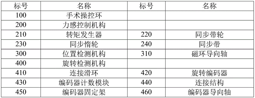
图1是本发明实施例提供的血管介入手术机器人主端操控装置的立体图;1 is a perspective view of a main end manipulation device of a vascular interventional surgery robot provided by an embodiment of the present invention;
图2是图1中AA方向剖视图。FIG. 2 is a cross-sectional view along the AA direction in FIG. 1 .
附图标号说明:Description of reference numbers:

具体实施方式Detailed ways
为了使本发明的目的、技术方案及优点更加清楚明白,以下结合附图及实施例,对本发明进行进一步详细说明。应当理解,此处所描述的具体实施例仅用以解释本发明,并不用于限定本发明。In order to make the objectives, technical solutions and advantages of the present invention clearer, the present invention will be further described in detail below with reference to the accompanying drawings and embodiments. It should be understood that the specific embodiments described herein are only used to explain the present invention, but not to limit the present invention.
本发明实施例提供一种血管介入手术机器人主端操控装置,与血管介入手术机器人从端执行装置配套使用,血管介入手术机器人从端执行装置抓持有导丝。Embodiments of the present invention provide a main-end control device for a vascular interventional surgery robot, which is used in conjunction with a vascular interventional surgery robot slave-end execution device, and the vascular interventional surgery robot slave-end execution device grasps a guide wire.
请参阅图1和图2,该血管介入手术机器人主端操控装置包括手术操控环 100、力感控制机构200、位置检测机构300以及旋转检测机构400。Please refer to FIG. 1 and FIG. 2 , the main-end manipulation device of the vascular interventional surgery robot includes a
手术操控环100供医生进行远程血管介入手术时直接操作的结构件,医生通过手术操控环100来远程控制血管介入手术机器人从端执行装置推拉、旋转导丝;手术操控环100的外表面可以设置有防滑结构,如套接防滑胶套或直接在手术操控环100的外表面设置凹凸,以避免医生操控手术操控环100时出现打滑的情况。The
力感控制机构200包括转矩发生器210、同步带240轮220、同步惰轮230 以及同步带240,转矩发生器210具有转矩输出轴,同步带240轮220连接于转矩输出轴,并随转矩输出轴转动,同步带240轮220和同步惰轮230的中心轴线平行,同步带240轮220和同步惰轮230共同张紧同步带240,同步轮220 用于带动同步带240走带,同步惰轮230随同步带240转动。在具体使用过程中,转矩发生器210在转矩输出轴输出的转矩与血管介入手术机器人从端执行装置受到的阻力直接关联,该关联是为了实现医生推动手术操控环100所受到的助力需与血管介入手术机器人从端执行装置推动导丝所受到的阻力大致相当,具体地,转矩发生器210产生相应地扭矩,通过同步带240、旋转检测机构400,将扭矩传递到手术操控环100,从而让医生在手术操控环100感受到力反馈。The force-sensing
位置检测机构300包括磁环导向轴310和位移传感器,磁环导向轴310的延伸方向垂直于述同步带240轮220的中心轴线,且平行同步带240轮220指向同步惰轮230的方向,手术操控环100套接于磁环导向轴310,并能够与磁环导向轴310相对转动,磁环导向轴310的外表面与手术操控环100的内环面光滑间隙配合,以避免手术操控环100相对磁环导向轴310移动、转动的过程中,产生过多的阻力,影响操作效果,其中,通过磁环导向轴310与手术操控环100的配合,限制手术操作环的活动方向,即手术操控环100只能沿磁环导向轴310的延伸方向滑动及相对磁环导向轴310转动,如此,便于与其他结构部件配合使用。位移传感器用于检测手术操控环100在磁环导向轴310的位置The
旋转检测机构400与同步带240连接,且还与手术操控环100转动连接,旋转检测机构400与手术操控环100之间的转动轴线平行同步带240轮220指向同步惰轮230的方向。该旋转检测机构400用于获取手术操控环100的转动情况,以便于根据手术操控环100的转动情况来让血管介入手术机器人从端执行装置控制对导丝的转动,具体地,通常是让手术操控环100的转动度数与导丝的转动度数一直。The
基于本发明的结构设计,首先,力感控制机构200能让医生操作手术操控环100时获取力反馈,医生能够有效的感知手术过程中导丝/导管在血管内的阻力,使得医生具有手术过程的力觉临场感,避免造成导丝/导管戳破血管,降低了引起大出血的风险,其次,旋转检测机构400能让医生操作手术操控环100 时无限制旋转,再次,通过位移传感器,位置检测机构300能让医生操作手术操控环100时准确获取手术操控环100推拉位置。Based on the structural design of the present invention, first of all, the force-sensing
具体地,在使用过程中,血管介入手术机器人主端操控装置,与血管介入手术机器人从端执行装置配套使用,医生手指操控手术操控环100进行推拉、旋转,从而获得在血管介入手术机器人主端操控装置获得医生手指操控,并将血管介入手术机器人主端操控装置获得的医生手指操控,在血管介入手术机器人从端执行装置进行模拟相应的手指操控。Specifically, during use, the main-end control device of the vascular interventional surgery robot is used together with the slave-end execution device of the vascular interventional surgery robot. The control device is controlled by the doctor's finger, and the doctor's finger control obtained by the main-end control device of the vascular interventional surgery robot is used to simulate the corresponding finger control on the slave-end execution device of the vascular interventional surgery robot.
在本发明中,通过手术操控环100、力感控制机构200、力感控制机构200 以及位置检测机构300的设计,相对于现有技术具有以下技术效果:In the present invention, the design of the
(1)医生操控手术操控环100时,能够有效获得力反馈,医生能够有效的感知手术过程中导丝/导管在血管内的阻力,使得医生具有手术过程的力觉临场感,避免造成导丝/导管戳破血管,降低了引起大出血的风险;(1) When the doctor manipulates the
(2)导丝/导管的旋转和推送动作能够一起执行,而且旋转的角度不限制,降低了手术操作的复杂程度;(2) The rotation and push action of the guide wire/catheter can be performed together, and the angle of rotation is not limited, which reduces the complexity of the surgical operation;
(3)符合医生平时常规手术两指操作导丝/导管进行介入手术的习惯,降低了医生学习机器人操作的难度。(3) It is in line with the doctor's habit of operating the guide wire/catheter for interventional surgery with two fingers in the usual operation, which reduces the difficulty of the doctor learning the robot operation.
在本发明实施例中,手术操控环100为磁环;位移传感器为磁致位移传感器,其中,手术操控环100为磁环,目的是配合磁致位移传感器的检测。磁致位移传感器的检测为非接触式检测,且具有精度高的优点,有利于提高血管介入手术机器人从端执行装置对导丝/导管的操控,避免出现导丝/导管戳破血管的情况,降低引起大出血的风险。In the embodiment of the present invention, the
如图1和图2所示,在本发明实施例中,旋转检测机构400包括连接滑环 410、旋转编码器420、编码器计数模块430以及连接结构440,连接滑环410 呈环形,连接滑环410套接于磁环导向轴310,并与磁环导向轴310转接配合,且与手术操控环100固定连接,旋转编码器420与连接滑环410转动连接,且旋转编码器420与连接滑环410之间的转动轴线平行同步带240轮220指向同步惰轮230的方向,编码器计数模块430与旋转编码器420电连接,连接结构 440与旋转编码器420固定连接,且还与同步带240固定连接。该结构简单,便于实现,有利于降低生产制造成本。As shown in FIG. 1 and FIG. 2 , in the embodiment of the present invention, the
进一步地,旋转检测机构400还包括编码器固定架450以及至少两个编码器导向轴460,编码器固定架450与旋转编码器420固定连接,各编码器导向轴460的延伸方向平行于磁环导向轴310的延伸方向,并均穿过编码器固定架 450,且均与编码器固定架450滑接配合。如此,有利于避免旋转编码器420 随手术操控环100移动的过程中发生晃动的情况。Further, the
进一步地,编码器固定架450通过直线轴承470来与编码器导向轴460滑接配合,可减小编码器固定架450与编码器导向轴460之间的摩擦阻力。Further, the
进一步地,连接结构440包括内压板和外压板,内压板和外压板共同夹紧同步带240,内压板和外压板至少其中之一与旋转编码器420固定连接。该结构简单,便于实现,有利于降低生产制造成本。Further, the
如图1和图2所示,在本发明实施例中,旋转编码器420呈中空环形,并套接于磁环导向轴310。As shown in FIG. 1 and FIG. 2 , in the embodiment of the present invention, the
在本发明实施例中,转矩发生器210为磁粉制动器,其中,磁粉制动器具有响应速度快、结构简单、无污染、无噪音、无冲击振动节约能源等优点,避免血管介入手术机器人主端操控装置使用过程中干扰医生的手术操作。In the embodiment of the present invention, the
如图1和图2所示,在本发明实施例中,血管介入手术机器人主端操控装置还包括电池500,电池500用于为转矩发生器210、位移传感器和旋转检测机构400供应电能。如此,在没有外部的电源的情况下,可利用电池500来保证血管介入手术机器人主端操控装置的正常使用。As shown in FIG. 1 and FIG. 2 , in the embodiment of the present invention, the main end manipulation device of the vascular interventional surgery robot further includes a
如图1和图2所示示,在本发明实施例中,血管介入手术机器人主端操控装置还包括装置底板610、转矩底座620、惰轮底座630以及支撑座640,转矩底座620、惰轮底座630和两支撑结构均固定于装置底板610,转矩底座620 供转矩发生器210固定,惰轮底座630通过惰轮轴650与同步惰轮230转接,支撑座640用于支撑磁环导向轴310。基于此结构设计,手术操控环100、力感控制机构200、力感控制机构200以及位置检测机构300直接或间接的固定在装置底板610,如此,便于血管介入手术机器人主端操控装置整体搬运、挪移。As shown in FIG. 1 and FIG. 2 , in the embodiment of the present invention, the main end manipulation device of the vascular interventional surgery robot further includes a
在本实施例中,支撑座640设有两个。In this embodiment, two
结合前述结构,导向轴460也固定于支撑座640。Combined with the aforementioned structure, the
以上所述仅为本发明的较佳实施例而已,并不用以限制本发明,凡在本发明的精神和原则之内所作的任何修改、等同替换或改进等,均应包含在本发明的保护范围之内。The above descriptions are only preferred embodiments of the present invention, and are not intended to limit the present invention. Any modifications, equivalent replacements or improvements made within the spirit and principles of the present invention shall be included in the protection of the present invention. within the range.
Claims (10)
Priority Applications (1)
| Application Number | Priority Date | Filing Date | Title |
|---|---|---|---|
| CN202011059867.6A CN112120791B (en) | 2020-09-30 | 2020-09-30 | Main end control device of vascular intervention surgical robot |
Applications Claiming Priority (1)
| Application Number | Priority Date | Filing Date | Title |
|---|---|---|---|
| CN202011059867.6A CN112120791B (en) | 2020-09-30 | 2020-09-30 | Main end control device of vascular intervention surgical robot |
Publications (2)
| Publication Number | Publication Date |
|---|---|
| CN112120791A true CN112120791A (en) | 2020-12-25 |
| CN112120791B CN112120791B (en) | 2021-12-31 |
Family
ID=73843364
Family Applications (1)
| Application Number | Title | Priority Date | Filing Date |
|---|---|---|---|
| CN202011059867.6A Active CN112120791B (en) | 2020-09-30 | 2020-09-30 | Main end control device of vascular intervention surgical robot |
Country Status (1)
| Country | Link |
|---|---|
| CN (1) | CN112120791B (en) |
Cited By (16)
| Publication number | Priority date | Publication date | Assignee | Title |
|---|---|---|---|---|
| CN112932675A (en) * | 2021-03-15 | 2021-06-11 | 上海交通大学 | Pipeline control device with multidimensional force sense feedback |
| CN113749779A (en) * | 2021-08-31 | 2021-12-07 | 深圳市爱博医疗机器人有限公司 | Intervention operation robot main end control device with anti-collision function |
| CN113827343A (en) * | 2021-10-12 | 2021-12-24 | 复旦大学 | A minimally invasive vascular interventional surgery robot operating device |
| CN114159156A (en) * | 2021-12-13 | 2022-03-11 | 成都信息工程大学 | Main end touch interaction device of vascular intervention surgical robot |
| CN114515194A (en) * | 2022-02-17 | 2022-05-20 | 山东威高医疗科技有限公司 | Guide wire driving device of blood vessel interventional robot |
| CN115040760A (en) * | 2022-07-14 | 2022-09-13 | 深圳微美机器人有限公司 | Control method of motion control device, and conveying system |
| WO2022258019A1 (en) * | 2021-06-10 | 2022-12-15 | 深圳市爱博医疗机器人有限公司 | Master operating handle of interventional surgical robot |
| WO2023029583A1 (en) * | 2021-08-31 | 2023-03-09 | 深圳市爱博医疗机器人有限公司 | Interventional surgical robot master end control device |
| CN116212199A (en) * | 2022-12-28 | 2023-06-06 | 河北工业大学 | A force feedback master end device for vascular interventional surgery |
| CN116236285A (en) * | 2023-03-14 | 2023-06-09 | 珠海市人民医院 | A vascular interventional surgery robot and its guide wire delivery mechanism |
| CN116370101A (en) * | 2023-04-18 | 2023-07-04 | 上海睿触科技有限公司 | A new master operating device for pan-vascular interventional surgery robot |
| WO2023125623A1 (en) * | 2021-12-31 | 2023-07-06 | 沛嘉医疗科技(苏州)有限公司 | Master-side control mechanism and surgical robot |
| CN116421319A (en) * | 2023-03-06 | 2023-07-14 | 极限人工智能有限公司 | Man-machine interaction device and method of vascular intervention surgical robot |
| WO2023142291A1 (en) * | 2022-01-29 | 2023-08-03 | 深圳市爱博医疗机器人有限公司 | Interventional surgery robot main end operation device |
| CN117323020A (en) * | 2023-10-11 | 2024-01-02 | 上海神玑医疗科技有限公司 | Operation robot master control end operation handle unit and master control end operation platform |
| CN117814924A (en) * | 2024-03-05 | 2024-04-05 | 北京中科鸿泰医疗科技有限公司 | Interventional operation robot doctor control end structure and interventional operation robot |
Citations (21)
| Publication number | Priority date | Publication date | Assignee | Title |
|---|---|---|---|---|
| GB692809A (en) * | 1950-10-13 | 1953-06-17 | Res Engineers Ltd | Improvements in profiling machines |
| US20050197557A1 (en) * | 2004-03-08 | 2005-09-08 | Mediguide Ltd. | Automatic guidewire maneuvering system and method |
| US20100179587A1 (en) * | 2009-01-15 | 2010-07-15 | Immersion Corporation | Providing Haptic Feedback To The Handle Of A Tool |
| CN103006328A (en) * | 2012-12-03 | 2013-04-03 | 北京航空航天大学 | Fuzzy fusion method for force feedback of vascular intervention surgical robot |
| CN103831832A (en) * | 2012-11-26 | 2014-06-04 | 苏茂 | Two-way force feedback slave manipulator arm control device |
| CN103976765A (en) * | 2014-05-16 | 2014-08-13 | 天津理工大学 | Master end operator device of master slave minimal invasive blood vessel interventional surgical assistant system |
| CN104042259A (en) * | 2014-05-16 | 2014-09-17 | 天津理工大学 | Slave manipulator device for auxiliary system of main and slave minimally invasive blood vessel interventional surgery |
| US20160082224A1 (en) * | 2012-12-31 | 2016-03-24 | Biosense Webster (Israel) Ltd. | Catheter with serially connected sensing structures and methods of calibration and detection |
| CN105534599A (en) * | 2016-01-27 | 2016-05-04 | 天津理工大学 | Vascular interventional operation robot main end force feedback device and working method thereof |
| CA2931877A1 (en) * | 2016-03-16 | 2016-08-02 | Synaptive Medical (Barbados) Inc. | Trajectory guidance alignment system and methods |
| CN205459038U (en) * | 2016-03-03 | 2016-08-17 | 北京理工大学 | Surgery robot from end is intervene to principal and subordinate wicresoft blood vessel |
| WO2016204437A1 (en) * | 2015-06-16 | 2016-12-22 | 한양대학교에리카산학협력단 | Vascular intervention robot and vascular intervention system |
| US20170007345A1 (en) * | 2006-12-01 | 2017-01-12 | Boston Scientific Scimed, Inc. | Medical systems comprising tool members |
| CN107106155A (en) * | 2017-04-01 | 2017-08-29 | 中国科学院深圳先进技术研究院 | The catheter propelling control method and catheter propelling equipment of blood vessel intervention operation robot |
| CN107307909A (en) * | 2017-07-06 | 2017-11-03 | 北京理工大学 | One kind intervention robot remote operating system and its control method |
| CN107744405A (en) * | 2017-08-31 | 2018-03-02 | 首都医科大学附属北京天坛医院 | A kind of robot is from end device, operating system and its control method |
| US10052458B2 (en) * | 2012-10-17 | 2018-08-21 | Worcester Polytechnic Institute | System and method for underactuated control of insertion path for asymmetric tip needles |
| CN109157287A (en) * | 2018-07-09 | 2019-01-08 | 南京航空航天大学 | A kind of conduit or seal wire running resistance and the robot of clamping force of capable of perceiving is from hand |
| CN110141365A (en) * | 2019-05-06 | 2019-08-20 | 清华大学 | Remote control system of vascular interventional surgery auxiliary device that simulates doctor's operation |
| CN210056225U (en) * | 2019-03-07 | 2020-02-14 | 天津理工大学 | Novel vascular intervention surgical robot catheter guide wire cooperative operation implementation device |
| CN111227946A (en) * | 2020-02-18 | 2020-06-05 | 燕山大学 | Minimally invasive vascular intervention operation robot operating device |
-
2020
- 2020-09-30 CN CN202011059867.6A patent/CN112120791B/en active Active
Patent Citations (21)
| Publication number | Priority date | Publication date | Assignee | Title |
|---|---|---|---|---|
| GB692809A (en) * | 1950-10-13 | 1953-06-17 | Res Engineers Ltd | Improvements in profiling machines |
| US20050197557A1 (en) * | 2004-03-08 | 2005-09-08 | Mediguide Ltd. | Automatic guidewire maneuvering system and method |
| US20170007345A1 (en) * | 2006-12-01 | 2017-01-12 | Boston Scientific Scimed, Inc. | Medical systems comprising tool members |
| US20100179587A1 (en) * | 2009-01-15 | 2010-07-15 | Immersion Corporation | Providing Haptic Feedback To The Handle Of A Tool |
| US10052458B2 (en) * | 2012-10-17 | 2018-08-21 | Worcester Polytechnic Institute | System and method for underactuated control of insertion path for asymmetric tip needles |
| CN103831832A (en) * | 2012-11-26 | 2014-06-04 | 苏茂 | Two-way force feedback slave manipulator arm control device |
| CN103006328A (en) * | 2012-12-03 | 2013-04-03 | 北京航空航天大学 | Fuzzy fusion method for force feedback of vascular intervention surgical robot |
| US20160082224A1 (en) * | 2012-12-31 | 2016-03-24 | Biosense Webster (Israel) Ltd. | Catheter with serially connected sensing structures and methods of calibration and detection |
| CN103976765A (en) * | 2014-05-16 | 2014-08-13 | 天津理工大学 | Master end operator device of master slave minimal invasive blood vessel interventional surgical assistant system |
| CN104042259A (en) * | 2014-05-16 | 2014-09-17 | 天津理工大学 | Slave manipulator device for auxiliary system of main and slave minimally invasive blood vessel interventional surgery |
| WO2016204437A1 (en) * | 2015-06-16 | 2016-12-22 | 한양대학교에리카산학협력단 | Vascular intervention robot and vascular intervention system |
| CN105534599A (en) * | 2016-01-27 | 2016-05-04 | 天津理工大学 | Vascular interventional operation robot main end force feedback device and working method thereof |
| CN205459038U (en) * | 2016-03-03 | 2016-08-17 | 北京理工大学 | Surgery robot from end is intervene to principal and subordinate wicresoft blood vessel |
| CA2931877A1 (en) * | 2016-03-16 | 2016-08-02 | Synaptive Medical (Barbados) Inc. | Trajectory guidance alignment system and methods |
| CN107106155A (en) * | 2017-04-01 | 2017-08-29 | 中国科学院深圳先进技术研究院 | The catheter propelling control method and catheter propelling equipment of blood vessel intervention operation robot |
| CN107307909A (en) * | 2017-07-06 | 2017-11-03 | 北京理工大学 | One kind intervention robot remote operating system and its control method |
| CN107744405A (en) * | 2017-08-31 | 2018-03-02 | 首都医科大学附属北京天坛医院 | A kind of robot is from end device, operating system and its control method |
| CN109157287A (en) * | 2018-07-09 | 2019-01-08 | 南京航空航天大学 | A kind of conduit or seal wire running resistance and the robot of clamping force of capable of perceiving is from hand |
| CN210056225U (en) * | 2019-03-07 | 2020-02-14 | 天津理工大学 | Novel vascular intervention surgical robot catheter guide wire cooperative operation implementation device |
| CN110141365A (en) * | 2019-05-06 | 2019-08-20 | 清华大学 | Remote control system of vascular interventional surgery auxiliary device that simulates doctor's operation |
| CN111227946A (en) * | 2020-02-18 | 2020-06-05 | 燕山大学 | Minimally invasive vascular intervention operation robot operating device |
Non-Patent Citations (1)
| Title |
|---|
| 张稳: "血管介入手术机器人操作主手设计及主从控制研究", 《中国优秀硕士学位论文全文数据库》 * |
Cited By (25)
| Publication number | Priority date | Publication date | Assignee | Title |
|---|---|---|---|---|
| CN112932675B (en) * | 2021-03-15 | 2022-12-20 | 上海交通大学 | Pipeline control device with multidimensional force sense feedback |
| CN112932675A (en) * | 2021-03-15 | 2021-06-11 | 上海交通大学 | Pipeline control device with multidimensional force sense feedback |
| WO2022258019A1 (en) * | 2021-06-10 | 2022-12-15 | 深圳市爱博医疗机器人有限公司 | Master operating handle of interventional surgical robot |
| CN113749779A (en) * | 2021-08-31 | 2021-12-07 | 深圳市爱博医疗机器人有限公司 | Intervention operation robot main end control device with anti-collision function |
| CN113749779B (en) * | 2021-08-31 | 2023-08-04 | 深圳市爱博医疗机器人有限公司 | Main end control device of interventional operation robot with error touch prevention function |
| WO2023029583A1 (en) * | 2021-08-31 | 2023-03-09 | 深圳市爱博医疗机器人有限公司 | Interventional surgical robot master end control device |
| WO2023029582A1 (en) * | 2021-08-31 | 2023-03-09 | 深圳市爱博医疗机器人有限公司 | Interventional surgical robot master end control apparatus having accidential-touch prevention function |
| CN113827343B (en) * | 2021-10-12 | 2023-10-03 | 复旦大学 | A minimally invasive vascular interventional surgery robot operating device |
| CN113827343A (en) * | 2021-10-12 | 2021-12-24 | 复旦大学 | A minimally invasive vascular interventional surgery robot operating device |
| CN114159156A (en) * | 2021-12-13 | 2022-03-11 | 成都信息工程大学 | Main end touch interaction device of vascular intervention surgical robot |
| CN114159156B (en) * | 2021-12-13 | 2023-09-29 | 成都信息工程大学 | A tactile interactive device for the main end of a vascular interventional surgery robot |
| WO2023125623A1 (en) * | 2021-12-31 | 2023-07-06 | 沛嘉医疗科技(苏州)有限公司 | Master-side control mechanism and surgical robot |
| WO2023142291A1 (en) * | 2022-01-29 | 2023-08-03 | 深圳市爱博医疗机器人有限公司 | Interventional surgery robot main end operation device |
| CN114515194A (en) * | 2022-02-17 | 2022-05-20 | 山东威高医疗科技有限公司 | Guide wire driving device of blood vessel interventional robot |
| CN114515194B (en) * | 2022-02-17 | 2024-06-11 | 山东威高医疗科技有限公司 | Vascular intervention robot guide wire driving device |
| CN115040760B (en) * | 2022-07-14 | 2024-05-24 | 深圳微美机器人有限公司 | Control method of motion control device, motion control device and conveying system |
| CN115040760A (en) * | 2022-07-14 | 2022-09-13 | 深圳微美机器人有限公司 | Control method of motion control device, and conveying system |
| CN116212199A (en) * | 2022-12-28 | 2023-06-06 | 河北工业大学 | A force feedback master end device for vascular interventional surgery |
| CN116421319A (en) * | 2023-03-06 | 2023-07-14 | 极限人工智能有限公司 | Man-machine interaction device and method of vascular intervention surgical robot |
| CN116236285A (en) * | 2023-03-14 | 2023-06-09 | 珠海市人民医院 | A vascular interventional surgery robot and its guide wire delivery mechanism |
| CN116370101A (en) * | 2023-04-18 | 2023-07-04 | 上海睿触科技有限公司 | A new master operating device for pan-vascular interventional surgery robot |
| CN117323020A (en) * | 2023-10-11 | 2024-01-02 | 上海神玑医疗科技有限公司 | Operation robot master control end operation handle unit and master control end operation platform |
| CN117323020B (en) * | 2023-10-11 | 2024-07-16 | 上海神玑医疗科技有限公司 | Operation robot master control end operation handle unit and master control end operation platform |
| CN117814924A (en) * | 2024-03-05 | 2024-04-05 | 北京中科鸿泰医疗科技有限公司 | Interventional operation robot doctor control end structure and interventional operation robot |
| CN117814924B (en) * | 2024-03-05 | 2024-06-11 | 北京中科鸿泰医疗科技有限公司 | Interventional surgery robot doctor control terminal structure and interventional surgery robot |
Also Published As
| Publication number | Publication date |
|---|---|
| CN112120791B (en) | 2021-12-31 |
Similar Documents
| Publication | Publication Date | Title |
|---|---|---|
| CN112120791A (en) | Main end control device of vascular intervention surgical robot | |
| CN105662589B (en) | Principal and subordinate's interventional surgery robot from end and its control method | |
| CN108888848B (en) | A robotic mechanical system for precision intervention of microfilament tubes | |
| CN109106449B (en) | Cardiovascular and cerebrovascular interventional operation robot and guide wire catheter pushing method thereof | |
| CN111084661A (en) | Operation support device, method of controlling the same, and recording medium | |
| CN113827343B (en) | A minimally invasive vascular interventional surgery robot operating device | |
| CN107184255A (en) | A kind of ultrasonic per rectum prostate biopsy mechanism | |
| CN114831739B (en) | Master-end multi-instrument operating device of master-slave minimally invasive vascular interventional operation robot | |
| CN116212199A (en) | A force feedback master end device for vascular interventional surgery | |
| CN111643188B (en) | A puncture surgery robot device | |
| CN113081276B (en) | A four-bar venous puncture advancing and retracting needle execution device with needle picking action | |
| WO2016111134A1 (en) | Operation input device and medical manipulator system | |
| CN114259301B (en) | Piercing structure, main hand controller and piercing robot | |
| He et al. | A venipuncture robot with decoupled position and attitude guided by near‐infrared vision and force feedback | |
| CN209301637U (en) | Personalized upper limb rehabilitation training robot | |
| CN103549997B (en) | A kind of operating robot being loaded with Force sensor clamps handss from handss | |
| CN117100407A (en) | Opening and closing input device, rotary input device, force feedback master hand and surgical robot | |
| CN207721863U (en) | A kind of prostate biopsy mechanism | |
| JP6427253B1 (en) | Medical equipment for robot control, drape adapter and operation support system | |
| CN219306926U (en) | Main hand control device for robot and surgical robot thereof | |
| Chen et al. | A novel clamping mechanism for circumferential force feedback device of the vascular interventional surgical robot | |
| Liu et al. | Mechanism design of the minimally invasive vascular interventional surgery robot system | |
| CN117122410A (en) | Main end control device with force feedback function and vascular intervention surgical robot | |
| CN110270000A (en) | Seal wire pushes power measurement device and seal wire driving means | |
| CN115590625B (en) | Force feedback operation device for endovascular interventional operation robot |
Legal Events
| Date | Code | Title | Description |
|---|---|---|---|
| PB01 | Publication | ||
| PB01 | Publication | ||
| SE01 | Entry into force of request for substantive examination | ||
| SE01 | Entry into force of request for substantive examination | ||
| GR01 | Patent grant | ||
| GR01 | Patent grant |