CN112068758A - Picture display method and related device - Google Patents
Picture display method and related device Download PDFInfo
- Publication number
- CN112068758A CN112068758A CN202010916802.2A CN202010916802A CN112068758A CN 112068758 A CN112068758 A CN 112068758A CN 202010916802 A CN202010916802 A CN 202010916802A CN 112068758 A CN112068758 A CN 112068758A
- Authority
- CN
- China
- Prior art keywords
- picture
- display area
- composite display
- moving
- movement
- Prior art date
- Legal status (The legal status is an assumption and is not a legal conclusion. Google has not performed a legal analysis and makes no representation as to the accuracy of the status listed.)
- Granted
Links
Images


Classifications
-
- G—PHYSICS
- G06—COMPUTING OR CALCULATING; COUNTING
- G06F—ELECTRIC DIGITAL DATA PROCESSING
- G06F3/00—Input arrangements for transferring data to be processed into a form capable of being handled by the computer; Output arrangements for transferring data from processing unit to output unit, e.g. interface arrangements
- G06F3/01—Input arrangements or combined input and output arrangements for interaction between user and computer
- G06F3/048—Interaction techniques based on graphical user interfaces [GUI]
- G06F3/0484—Interaction techniques based on graphical user interfaces [GUI] for the control of specific functions or operations, e.g. selecting or manipulating an object, an image or a displayed text element, setting a parameter value or selecting a range
- G06F3/04845—Interaction techniques based on graphical user interfaces [GUI] for the control of specific functions or operations, e.g. selecting or manipulating an object, an image or a displayed text element, setting a parameter value or selecting a range for image manipulation, e.g. dragging, rotation, expansion or change of colour
Landscapes
- Engineering & Computer Science (AREA)
- General Engineering & Computer Science (AREA)
- Theoretical Computer Science (AREA)
- Human Computer Interaction (AREA)
- Physics & Mathematics (AREA)
- General Physics & Mathematics (AREA)
- User Interface Of Digital Computer (AREA)
Abstract
The application discloses a picture display method and a related device, which are applied to a mobile terminal, wherein the mobile terminal comprises a composite display area, and two pictures with different effects aiming at the same target object are arranged in the composite display area: the picture comprises a first picture and a second picture, wherein the first picture is positioned above the second picture. The composite display area is also provided with a moving shaft which is used for controlling the display of the first picture and the second picture in the composite display area. Specifically, first, a moving operation for the moving axis is acquired. Then, the movement axis is moved in the composite display area according to the movement operation. And finally, controlling the display range of the first picture and the second picture in the composite display area based on the movement of the moving shaft. Therefore, the position of the moving shaft in the composite area is adjusted through moving operation, the display ranges of the first picture and the second picture in the composite display area are adjusted, multiple pictures with different effects before and after the target object in the pictures is changed are displayed in a limited area, and the experience of a user is improved.
Description
Technical Field
The present invention relates to the field of mobile terminal technologies, and in particular, to a picture display method and a related device.
Background
With the development of mobile terminals, users can implement various application functions through the mobile terminals, wherein the most common is to browse pictures through the mobile terminals. When a mobile terminal is used to browse pictures, a complete picture is generally displayed on a screen of the mobile terminal, or multiple pictures are displayed on the screen in a list form for a user to browse.
However, in a scene where a picture comparison is required, for example, in a scene where a room is decorated and the like, due to the limited screen size of the mobile terminal, the display area of the picture is limited, if only one complete picture is displayed in the display area, the comparison condition before and after the change of the target object in the picture cannot be reflected, if multiple pictures are respectively displayed in multiple display areas for the target object, the limited display area in the mobile terminal may be wasted, if multiple sub-display areas are divided in the original display area for displaying multiple pictures, the specific details before and after the change of the target object in the picture cannot be seen by the user, and the user experience is poor.
Disclosure of Invention
In view of the above problems, the present application provides a picture comparison method and a related device, which can display multiple pictures with different effects before and after a target object in a picture is changed in a limited region, thereby improving user experience.
A first aspect of the present application provides a picture display method, which is applied to a mobile terminal, where the mobile terminal includes a composite display area, a first picture and a second picture are both in the composite display area, the first picture covers the second picture, the first picture and the second picture are two pictures with different effects for a same target object, the composite display area has a movement axis, and the movement axis is used to control the first picture and the second picture to be displayed in the composite display area; the method comprises the following steps:
acquiring a moving operation for the moving axis;
moving the moving axis in the composite display area according to the moving operation;
controlling a display range of the first picture and the second picture in the composite display area based on the movement of the movement axis.
Optionally, the controlling the display range of the first picture and the second picture in the composite display area based on the movement of the movement axis includes:
when the moving shaft moves towards a first direction, controlling the first picture to move along with the moving shaft so as to reduce the display range of the first picture in the composite display area and increase the display range of the second picture in the composite display area;
when the moving shaft moves towards a second direction, controlling the first picture to move along with the moving shaft so as to increase the display range of the first picture in the composite display area and reduce the display range of the second picture in the composite display area; the first direction and the second direction are opposite.
Optionally, the controlling the display range of the first picture and the second picture in the composite display area based on the movement of the movement axis includes:
when the moving shaft moves towards a first direction, controlling the first picture to cover the range of the second picture so as to reduce the display range of the first picture in the composite display area and increase the display range of the second picture in the composite display area;
when the moving shaft moves towards a second direction, controlling the first picture to cover the range of the second picture so as to increase the display range of the first picture in the composite display area and reduce the display range of the second picture in the composite display area; the first direction and the second direction are opposite.
Optionally, the moving axis has one, and is located at a first direction side of the composite display area or a second direction side of the composite display area.
Optionally, the two moving axes are respectively located at the first direction side of the composite display area and the second direction side of the composite display area.
Optionally, the first direction is left, right, up or down, and the second direction is right, left, down or up.
Optionally, after moving the moving axis in the composite display area according to the moving operation, the method further includes:
the moving shaft is fixed in the composite display area.
A second aspect of the present application provides a device for displaying pictures, which is applied to a mobile terminal, where the mobile terminal includes a composite display area, a first picture and a second picture are both in the composite display area, the first picture covers the second picture, the first picture and the second picture are two pictures with different effects for a same target object, the composite display area has a movement axis, and the movement axis is used to control the first picture and the second picture to be displayed in the composite display area; the device comprises:
an acquisition unit configured to acquire a movement operation for the movement axis;
a moving unit for moving the moving axis in the composite display area according to the moving operation;
a control unit configured to control a display range of the first picture and the second picture in the composite display area based on movement of the movement axis.
Optionally, the control unit is specifically configured to:
when the moving shaft moves towards a first direction, controlling the first picture to move along with the moving shaft so as to reduce the display range of the first picture in the composite display area and increase the display range of the second picture in the composite display area;
when the moving shaft moves towards a second direction, controlling the first picture to move along with the moving shaft so as to increase the display range of the first picture in the composite display area and reduce the display range of the second picture in the composite display area; the first direction and the second direction are opposite.
Optionally, the control unit is specifically configured to:
when the moving shaft moves towards a first direction, controlling the first picture to cover the range of the second picture so as to reduce the display range of the first picture in the composite display area and increase the display range of the second picture in the composite display area;
when the moving shaft moves towards a second direction, controlling the first picture to cover the range of the second picture so as to increase the display range of the first picture in the composite display area and reduce the display range of the second picture in the composite display area; the first direction and the second direction are opposite.
Optionally, the moving axis has one, and is located at a first direction side of the composite display area or a second direction side of the composite display area.
Optionally, the two moving axes are respectively located at the first direction side of the composite display area and the second direction side of the composite display area.
Optionally, the first direction is left, right, up or down, and the second direction is right, left, down or up.
Optionally, the apparatus further includes a fixing unit configured to fix the moving shaft in the composite display area after the moving shaft moves.
A third aspect of the present application provides an apparatus for picture display, the apparatus comprising a processor and a memory:
the memory is used for storing a computer program and transmitting the computer program to the processor;
the processor is configured to perform the method of any one of the above in accordance with instructions in the computer program.
A fourth aspect of the present application provides a computer-readable storage medium for storing a computer program for performing the method of any one of the above.
Compared with the prior art, the technical scheme of the application has the advantages that:
by adopting the technical scheme provided by the application, the method is applied to the mobile terminal, the mobile terminal comprises a composite display area, and two pictures aiming at different effects of the same target object are arranged in the composite display area: the picture processing device comprises a first picture and a second picture, wherein the first picture is located above the second picture, and the first picture can shield the second picture. The composite display area is also provided with a moving shaft which is used for controlling the display of the first picture and the second picture in the composite display area. Specifically, first, a moving operation for the moving axis is acquired. Then, the movement axis is moved in the composite display area according to the movement operation. And finally, controlling the display range of the first picture and the second picture in the composite display area based on the movement of the moving shaft. Therefore, the position of the moving shaft in the composite area is adjusted through moving operation, the display range of the first picture and the display range of the second picture in the composite display area are adjusted, the first picture and the second picture are compared and checked, multiple pictures with different effects before and after the target object changes in the pictures are displayed in a limited area, the convenience of comparing and checking the multiple pictures is improved, and the experience of a user is improved.
Drawings
In order to more clearly illustrate the embodiments of the present application or the technical solutions in the prior art, the drawings needed to be used in the description of the embodiments or the prior art will be briefly described below, it is obvious that the drawings in the following description are only some embodiments described in the present application, and other drawings can be obtained by those skilled in the art without creative efforts.
Fig. 1 is a flowchart of a picture display method according to an embodiment of the present disclosure;
fig. 2 is a schematic diagram of a mobile terminal according to an image display method provided in an embodiment of the present application;
FIG. 3 is a schematic diagram of a shift axis position in a composite display area according to an embodiment of the present disclosure;
FIG. 4 is a schematic diagram of a shift axis position in a composite display area according to an embodiment of the present application;
fig. 5 is a schematic diagram of another picture display method according to an embodiment of the present disclosure;
fig. 6 is a schematic diagram of another image display method according to an embodiment of the present application;
fig. 7 is a schematic diagram of an image display device according to an embodiment of the present disclosure;
fig. 8 is a device for displaying pictures according to an embodiment of the present disclosure;
fig. 9 is a schematic diagram of a computer-readable storage medium according to an embodiment of the present application.
Detailed Description
In order to make the technical solutions of the present application better understood, the technical solutions in the embodiments of the present application will be clearly and completely described below with reference to the drawings in the embodiments of the present application, and it is obvious that the described embodiments are only a part of the embodiments of the present application, and not all of the embodiments. All other embodiments, which can be derived by a person skilled in the art from the embodiments given herein without making any creative effort, shall fall within the protection scope of the present application.
Referring to fig. 1, fig. 1 is a flowchart of a picture displaying method provided in the present application, which may include the following steps 101-103.
S101: a movement operation for the movement axis is acquired.
The picture display method provided by the application is applied to the mobile terminal, and as shown in fig. 2, the picture is a schematic diagram of the picture display method provided by the embodiment of the application on the mobile terminal. The mobile terminal 200 includes a composite display area for displaying picture information. The number of composite display areas included in the mobile terminal 200 is not specifically limited in the embodiment of the present application, and the embodiment takes one composite display area 210 in the mobile terminal 200 as an example for description.
The composite display area 210 includes a first picture 211 and a second picture 212. The first picture and the second picture are two pictures with different effects for the same target object, for example, two pictures before and after decoration of the same room. For another example, two pictures before and after the same face image is beautified. The first picture 211 is overlaid on the second picture 212. The coverage range is not particularly limited in the embodiment of the present application, for example, the first picture 211 may be entirely covered on the second picture 212. For another example, the first picture 211 may partially overlap the second picture 212 (as shown in fig. 2, the first picture overlaps eighty percent of the second picture). The first picture 211 can be a picture requiring a prominent effect, such as a finished picture, and the second picture 212 can be a reference picture compared to the first picture, such as a picture before finishing.
There is also a movement axis 220 in the composite display area, the movement axis 220 being used to control the display of the first picture 211 and the second picture 212 in the composite display area 210.
There are various kinds of movement operations for the movement axis 220, and there are different cases of movement operations depending on the position of the movement axis 220. For convenience of description, two sides of the mobile terminal 200 are defined as a vertical direction and a horizontal direction, and as shown in fig. 3, a long side of the mobile terminal 200 is in the vertical direction, and a short side of the mobile terminal 200 is in the horizontal direction. When the extending direction of the moving shaft 220 is the vertical direction, the moving operations of the moving shaft 220 are leftward and rightward movement, respectively, as shown in fig. 3. When the extending direction of the moving shaft 220 is the horizontal direction, the moving operation of the moving shaft 220 is upward movement and downward movement, respectively, as shown in fig. 4.
S102: moving the movement axis in the composite display area according to the movement operation.
After the movement operation is acquired, the movement axis 220 is moved in the composite display area 210 according to the movement operation. For example, in the case where the moving shaft 220 is in the vertical direction as shown in fig. 3, when the moving operation is to move leftward, the moving shaft 220 is moved leftward; when the moving operation is to the right, the moving shaft 220 is moved to the right.
The number of the moving axes 220 is not particularly limited in the embodiment of the present application. For example, there is a movement axis in the composite display area, located at an arbitrary position in the composite display area. As another example, there are two axes of movement in the composite display area, each located at two opposite positions in the composite display area, e.g., a first axis of movement is located on the left side of the composite display area and a second axis of movement is located on the right side of the composite display area. For another example, the first axis of movement is located at an upper side of the composite display area and the second axis of movement is located at a lower side of the composite display area.
S103: controlling a display range of the first picture and the second picture in the composite display area based on the movement of the movement axis.
Based on the movement of the movement axis 220, the display range of the first picture 211 in the composite display area 210 is controlled to increase or decrease, while the display range of the second picture 212 in the composite display area 210 decreases or increases.
By adopting the technical scheme provided by the application, the method is applied to the mobile terminal, the mobile terminal comprises a composite display area, and two pictures aiming at different effects of the same target object are arranged in the composite display area: the picture processing device comprises a first picture and a second picture, wherein the first picture is located above the second picture, and the first picture can shield the second picture. The composite display area is also provided with a moving shaft which is used for controlling the display of the first picture and the second picture in the composite display area. Specifically, first, a moving operation for the moving axis is acquired. Then, the movement axis is moved in the composite display area according to the movement operation. And finally, controlling the display range of the first picture and the second picture in the composite display area based on the movement of the moving shaft. Therefore, the position of the moving shaft in the composite area is adjusted through moving operation, the display range of the first picture and the display range of the second picture in the composite display area are flexibly adjusted, the first picture and the second picture are compared and checked, multiple pictures with different effects before and after the target object changes in the pictures can be displayed in a limited area, the convenience of comparing and checking the multiple pictures is improved, and the experience of a user is improved.
As a possible implementation, after moving the movement axis in the composite display area according to the movement operation, the movement axis may be fixed in the composite display area instead of automatically returning to the position before the movement operation, so that the user can compare and view the difference between the first picture and the second picture.
As a possible implementation manner, an instruction that the user clicks the first picture or the second picture in the composite display area may be obtained, so that the user jumps to the detail introduction interface of the first picture or the second picture.
As a possible implementation, the first picture and the second picture may be distinguished by the identification. For example, when the first picture is a finished picture, a graphic representation of "After" may be displayed on the first picture, and when the second picture is a picture Before finishing, a graphic representation of "Before" may be displayed on the second picture.
In order to make the technical solutions provided by the embodiments of the present application clearer, the following describes the picture display method provided by the embodiments of the present application with two examples in conjunction with fig. 5 and fig. 6.
The following description will be given by taking the extending direction of the moving shaft 220 as the vertical direction as an example, and it is understood that the display method is similar when the extending direction of the moving shaft 220 is the horizontal direction, and the description thereof is omitted.
Referring to fig. 5, the figure is a schematic view of another picture display method provided in the embodiment of the present application.
The following description will be given taking the first direction as the left direction and the second direction as the right direction as an example. Other moving directions are similar to those of the embodiments of the present application and are not described herein again. In this embodiment, there is a moving axis located at the right side of the composite display area, and the first picture moves along with the movement of the moving axis.
When the moving axis 220 moves from the default position to the left (from example a to example b), the left side of the first picture 211 is pushed out of the composite display area 210 as the moving axis 220 moves to the left, and the more the moving axis 220 moves to the left, the more the left side of the first picture 211 is pushed out of the composite display area 210, the smaller the display range thereof. Since the first picture 211 is hidden above the second picture 212, when the display range of the composite display region 210 gradually decreases along with the movement of the movement axis 220, the display range of the composite display region of the second picture 212 gradually increases.
Similarly, when the first picture 211 is moved rightward from the left position (from example b to example c) with the movement axis 220, the right side of the first picture 211 is pushed back to the composite display area 210 with the movement axis 220 moving rightward, the more the movement axis moves rightward, the more the left side of the first picture 211 is pushed back to the composite display area 210, and the larger the display range thereof. Since the first picture 211 is hidden above the second picture 212, when the display range of the first picture 211 in the composite display region 210 gradually increases along with the movement of the movement axis 220, the display range of the composite display region of the second picture 212 gradually decreases.
As shown in fig. 5, the display ranges of the first picture 211 and the second picture 212 in the composite display area 210 can be adjusted by moving the shaft 220 to the left and right in the composite display area 210, so as to distinguish between the furniture placed in the room and the furniture not placed in the room. And then can be in limited area, two pictures before and after the room decoration in the composite display area show, improved the convenience that the picture contrast was looked over before and after the room decoration, improved user's experience and felt.
As a possible implementation, the moving axis may have two, respectively located at the left and right sides of the composite display area. Different effects before and after the change of the right part of the target object can be emphatically contrasted and checked by adjusting the moving axis on the right side of the composite display area in the left-right direction; by adjusting the movement axis on the left side of the composite display area in the left-right direction, different effects before and after the change of the left part of the viewing target object can be emphasized and compared.
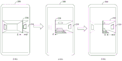
Referring to fig. 6, the figure is a schematic view of another picture display method provided in the embodiment of the present application.
The following description will be given taking the first direction as the left direction and the second direction as the right direction as an example. Other moving directions are similar to those of the embodiments of the present application and are not described herein again. In this embodiment, there is a moving axis located at the right side of the composite display area, and the first picture does not move with the movement of the moving axis.
When the moving axis 220 moves leftward from the default position (from example a to example b), the first picture 211 does not move with the movement of the moving axis 220, but the coverage of the first picture 211 over the second picture 212 gradually decreases, so that the display range of the second picture 212 in the composite display area 210 gradually increases.
Similarly, when the moving axis 220 moves from left to right (from example b to example c), the coverage of the first picture 211 on the second picture 212 gradually increases with the movement of the moving axis 220, so that the display range of the first picture 211 on the composite display region 210 gradually increases and the display range of the second picture 212 on the composite display region 210 gradually decreases.
As shown in fig. 6, the display ranges of the first picture 211 and the second picture 212 in the composite display area 210 can be adjusted by moving the axis 220 to the left and right in the composite display area 210, so as to distinguish between the furniture placed in the room and the furniture not placed in the room. And then can be in limited area, two contrast pictures before and after the room decoration are shown in the composite display area promptly, improved the convenience that the picture contrast was looked over before and after the room decoration, improved user's experience and felt.
In addition to the image display method, an embodiment of the present application further provides an image display apparatus, as shown in fig. 7, including an obtaining unit 701, a moving unit 702, and a control unit 703. Wherein:
an acquisition unit 701 configured to acquire a movement operation for the movement axis;
a moving unit 702 for moving the moving axis in the composite display area according to the moving operation;
a control unit 703 configured to control a display range of the first picture and the second picture in the composite display area based on the movement of the movement axis.
As a possible implementation manner, the control unit 703 is specifically configured to control the first picture to move along with the moving axis when the moving axis moves towards the first direction, so as to reduce the display range of the first picture in the composite display area and increase the display range of the second picture in the composite display area;
when the moving shaft moves towards a second direction, controlling the first picture to move along with the moving shaft so as to increase the display range of the first picture in the composite display area and reduce the display range of the second picture in the composite display area; the first direction and the second direction are opposite.
As a possible implementation manner, the control unit 703 is specifically configured to control the first picture to cover the range of the second picture when the moving axis moves towards the first direction, so as to reduce the display range of the first picture in the composite display area and increase the display range of the second picture in the composite display area;
when the moving shaft moves towards a second direction, controlling the first picture to cover the range of the second picture so as to increase the display range of the first picture in the composite display area and reduce the display range of the second picture in the composite display area; the first direction and the second direction are opposite.
As a possible implementation, the movement axis has one, located on the first direction side of the composite display area or the second direction side of the composite display area.
As a possible implementation, the movement axis has two, respectively located on the first direction side of the composite display area and the second direction side of the composite display area.
As a possible implementation manner, the first direction is left, right, up or down, and correspondingly, the second direction is right, left, down or up.
As a possible implementation manner, the apparatus further includes a fixing unit configured to fix the moving axis in the composite display area after moving the moving axis.
An apparatus for displaying a picture according to an embodiment of the present application is provided, and referring to fig. 8, this figure shows an apparatus structure diagram for displaying a picture according to an embodiment of the present application, and as shown in fig. 8, the apparatus includes a processor 810 and a memory 820:
the memory 810 is used for storing a computer program and transmitting the computer program to the processor;
the processor 820 is configured to execute the method for displaying pictures described in the above embodiments according to the instructions in the computer program.
An embodiment of the present application provides a computer-readable storage medium, refer to fig. 9, which shows a schematic diagram of a computer-readable storage medium provided in an embodiment of the present application, as shown in fig. 9, the computer-readable storage medium is used for storing a computer program 910, and the computer program 910 is used for executing the method for displaying a picture described in the foregoing embodiment.
The embodiments in the present specification are described in a progressive manner, and the same and similar parts among the embodiments are referred to each other, and each embodiment focuses on the differences from the other embodiments. In particular, for the apparatus embodiment, since it is substantially similar to the method embodiment, it is relatively simple to describe, and reference may be made to some descriptions of the method embodiment for relevant points. The above-described apparatus embodiments are merely illustrative, and the units and modules described as separate components may or may not be physically separate. In addition, some or all of the units and modules may be selected according to actual needs to achieve the purpose of the solution of the embodiment. One of ordinary skill in the art can understand and implement it without inventive effort.
The foregoing is directed to embodiments of the present application and it is noted that numerous modifications and adaptations may be made by those skilled in the art without departing from the principles of the present application and are intended to be within the scope of the present application.
Claims (10)
1. A picture display method is characterized in that the method is applied to a mobile terminal, the mobile terminal comprises a composite display area, a first picture and a second picture are both positioned in the composite display area, the first picture covers the second picture, the first picture and the second picture are two pictures with different effects aiming at the same target object, the composite display area is provided with a moving axis, and the moving axis is used for controlling the first picture and the second picture to be displayed in the composite display area; the method comprises the following steps:
acquiring a moving operation for the moving axis;
moving the moving axis in the composite display area according to the moving operation;
controlling a display range of the first picture and the second picture in the composite display area based on the movement of the movement axis.
2. The method according to claim 1, wherein the controlling a display range of the first picture and the second picture in the composite display area based on the movement of the movement axis comprises:
when the moving shaft moves towards a first direction, controlling the first picture to move along with the moving shaft so as to reduce the display range of the first picture in the composite display area and increase the display range of the second picture in the composite display area;
when the moving shaft moves towards a second direction, controlling the first picture to move along with the moving shaft so as to increase the display range of the first picture in the composite display area and reduce the display range of the second picture in the composite display area; the first direction and the second direction are opposite.
3. The method according to claim 1, wherein the controlling a display range of the first picture and the second picture in the composite display area based on the movement of the movement axis comprises:
when the moving shaft moves towards a first direction, controlling the first picture to cover the range of the second picture so as to reduce the display range of the first picture in the composite display area and increase the display range of the second picture in the composite display area;
when the moving shaft moves towards a second direction, controlling the first picture to cover the range of the second picture so as to increase the display range of the first picture in the composite display area and reduce the display range of the second picture in the composite display area; the first direction and the second direction are opposite.
4. The method according to any one of claims 1 to 3, wherein the movement axis has one located at a first directional side of the composite display area or a second directional side of the composite display area.
5. The method according to any one of claims 1 to 3, wherein the moving axis has two, respectively located on a first direction side of the composite display area and a second direction side of the composite display area.
6. A method according to claim 2 or 3, wherein the first direction is left, right, up or down, and correspondingly the second direction is right, left, down or up.
7. The method of claim 1, wherein after moving the movement axis in the composite display area according to the movement operation, further comprising:
the moving shaft is fixed in the composite display area.
8. A picture display device is characterized in that the device is applied to a mobile terminal, the mobile terminal comprises a composite display area, a first picture and a second picture are both positioned in the composite display area, the first picture covers the second picture, the first picture and the second picture are two pictures with different effects aiming at the same target object, the composite display area is provided with a moving axis, and the moving axis is used for controlling the first picture and the second picture to be displayed in the composite display area; the device comprises:
an acquisition unit configured to acquire a movement operation for the movement axis;
a moving unit for moving the moving axis in the composite display area according to the moving operation;
a control unit configured to control a display range of the first picture and the second picture in the composite display area based on movement of the movement axis.
9. An apparatus for picture display, the apparatus comprising a processor and a memory:
the memory is used for storing a computer program and transmitting the computer program to the processor;
the processor is adapted to perform the method of any of claims 1-7 according to instructions in the computer program.
10. A computer-readable storage medium, characterized in that the computer-readable storage medium is used to store a computer program for performing the method of any one of claims 1-7.
Priority Applications (1)
| Application Number | Priority Date | Filing Date | Title |
|---|---|---|---|
| CN202010916802.2A CN112068758B (en) | 2020-09-03 | 2020-09-03 | Picture display method and related device |
Applications Claiming Priority (1)
| Application Number | Priority Date | Filing Date | Title |
|---|---|---|---|
| CN202010916802.2A CN112068758B (en) | 2020-09-03 | 2020-09-03 | Picture display method and related device |
Publications (2)
| Publication Number | Publication Date |
|---|---|
| CN112068758A true CN112068758A (en) | 2020-12-11 |
| CN112068758B CN112068758B (en) | 2022-01-28 |
Family
ID=73665711
Family Applications (1)
| Application Number | Title | Priority Date | Filing Date |
|---|---|---|---|
| CN202010916802.2A Active CN112068758B (en) | 2020-09-03 | 2020-09-03 | Picture display method and related device |
Country Status (1)
| Country | Link |
|---|---|
| CN (1) | CN112068758B (en) |
Cited By (1)
| Publication number | Priority date | Publication date | Assignee | Title |
|---|---|---|---|---|
| CN112596836A (en) * | 2020-12-23 | 2021-04-02 | 北京城市网邻信息技术有限公司 | House source data processing method and device |
Citations (3)
| Publication number | Priority date | Publication date | Assignee | Title |
|---|---|---|---|---|
| US20120194558A1 (en) * | 2011-01-31 | 2012-08-02 | The Government Of The United States, As Represented By The Secretary Of The Navy | Meteorology and oceanography geospatial analysis toolset |
| CN108255387A (en) * | 2016-12-29 | 2018-07-06 | 广东中科遥感技术有限公司 | Touch screen mobile terminal image rapid comparison exchange method |
| CN108876876A (en) * | 2018-07-10 | 2018-11-23 | 云南电网有限责任公司信息中心 | A kind of roller shutter methods of exhibiting of Temporal GIS edition data comparison |
-
2020
- 2020-09-03 CN CN202010916802.2A patent/CN112068758B/en active Active
Patent Citations (3)
| Publication number | Priority date | Publication date | Assignee | Title |
|---|---|---|---|---|
| US20120194558A1 (en) * | 2011-01-31 | 2012-08-02 | The Government Of The United States, As Represented By The Secretary Of The Navy | Meteorology and oceanography geospatial analysis toolset |
| CN108255387A (en) * | 2016-12-29 | 2018-07-06 | 广东中科遥感技术有限公司 | Touch screen mobile terminal image rapid comparison exchange method |
| CN108876876A (en) * | 2018-07-10 | 2018-11-23 | 云南电网有限责任公司信息中心 | A kind of roller shutter methods of exhibiting of Temporal GIS edition data comparison |
Non-Patent Citations (1)
| Title |
|---|
| 盛光晓: "「图解」ArcGIS中的卷帘功能", 《麻辣GIS》 * |
Cited By (1)
| Publication number | Priority date | Publication date | Assignee | Title |
|---|---|---|---|---|
| CN112596836A (en) * | 2020-12-23 | 2021-04-02 | 北京城市网邻信息技术有限公司 | House source data processing method and device |
Also Published As
| Publication number | Publication date |
|---|---|
| CN112068758B (en) | 2022-01-28 |
Similar Documents
| Publication | Publication Date | Title |
|---|---|---|
| CN110692031B (en) | System and method for window control in a virtual reality environment | |
| US11231845B2 (en) | Display adaptation method and apparatus for application, and storage medium | |
| EP3525473A1 (en) | Panoramic image display control method and apparatus, and storage medium | |
| US11003305B2 (en) | 3D user interface | |
| US10049490B2 (en) | Generating virtual shadows for displayable elements | |
| CN107832001B (en) | Information processing method, information processing device, electronic equipment and storage medium | |
| TWI660304B (en) | Virtual reality real-time navigation method and system | |
| CN111467803B (en) | Display control method and device in game, storage medium and electronic equipment | |
| DE202014006254U1 (en) | Mobile terminal | |
| CN113559501B (en) | Virtual unit selection method and device in game, storage medium and electronic equipment | |
| CN109876439B (en) | Game picture display method and device, storage medium and electronic equipment | |
| CN113082696B (en) | Display control method and device and electronic equipment | |
| CN109731329B (en) | Method and device for determining placement position of virtual component in game | |
| CN113648661B (en) | Method and device for processing information in game, electronic equipment and storage medium | |
| EP4684267A1 (en) | Devices, methods, and graphical user interfaces for capturing media with a camera application | |
| US10127715B2 (en) | 3D user interface—non-native stereoscopic image conversion | |
| CN112965773A (en) | Method, apparatus, device and storage medium for information display | |
| CN112068758B (en) | Picture display method and related device | |
| CN112905280B (en) | Page display method, device, equipment and storage medium | |
| CN116596611A (en) | Commodity object information display method and electronic equipment | |
| CN113038050B (en) | Split screen display control method and device, terminal equipment and storage medium | |
| CN107982916B (en) | Information processing method, information processing device, electronic equipment and storage medium | |
| US20210274035A1 (en) | Method for anti-disturbing, electronic device, and computer-readable storage medium | |
| CN111800544B (en) | Panoramic dynamic screen protection method | |
| KR20190129982A (en) | Electronic device and its control method |
Legal Events
| Date | Code | Title | Description |
|---|---|---|---|
| PB01 | Publication | ||
| PB01 | Publication | ||
| SE01 | Entry into force of request for substantive examination | ||
| SE01 | Entry into force of request for substantive examination | ||
| GR01 | Patent grant | ||
| GR01 | Patent grant |