CN111983211A - Detection device and receiving device - Google Patents
Detection device and receiving device Download PDFInfo
- Publication number
- CN111983211A CN111983211A CN202010642152.7A CN202010642152A CN111983211A CN 111983211 A CN111983211 A CN 111983211A CN 202010642152 A CN202010642152 A CN 202010642152A CN 111983211 A CN111983211 A CN 111983211A
- Authority
- CN
- China
- Prior art keywords
- cavity
- piercing
- liquid
- fluid
- sealed
- Prior art date
- Legal status (The legal status is an assumption and is not a legal conclusion. Google has not performed a legal analysis and makes no representation as to the accuracy of the status listed.)
- Pending
Links
Images


Classifications
-
- B—PERFORMING OPERATIONS; TRANSPORTING
- B01—PHYSICAL OR CHEMICAL PROCESSES OR APPARATUS IN GENERAL
- B01L—CHEMICAL OR PHYSICAL LABORATORY APPARATUS FOR GENERAL USE
- B01L3/00—Containers or dishes for laboratory use, e.g. laboratory glassware; Droppers
- B01L3/50—Containers for the purpose of retaining a material to be analysed, e.g. test tubes
- B01L3/502—Containers for the purpose of retaining a material to be analysed, e.g. test tubes with fluid transport, e.g. in multi-compartment structures
- B01L3/5023—Containers for the purpose of retaining a material to be analysed, e.g. test tubes with fluid transport, e.g. in multi-compartment structures with a sample being transported to, and subsequently stored in an absorbent for analysis
-
- G—PHYSICS
- G01—MEASURING; TESTING
- G01N—INVESTIGATING OR ANALYSING MATERIALS BY DETERMINING THEIR CHEMICAL OR PHYSICAL PROPERTIES
- G01N33/00—Investigating or analysing materials by specific methods not covered by groups G01N1/00 - G01N31/00
- G01N33/48—Biological material, e.g. blood, urine; Haemocytometers
-
- B—PERFORMING OPERATIONS; TRANSPORTING
- B01—PHYSICAL OR CHEMICAL PROCESSES OR APPARATUS IN GENERAL
- B01L—CHEMICAL OR PHYSICAL LABORATORY APPARATUS FOR GENERAL USE
- B01L3/00—Containers or dishes for laboratory use, e.g. laboratory glassware; Droppers
- B01L3/02—Burettes; Pipettes
- B01L3/021—Pipettes, i.e. with only one conduit for withdrawing and redistributing liquids
- B01L3/0217—Pipettes, i.e. with only one conduit for withdrawing and redistributing liquids of the plunger pump type
- B01L3/0224—Pipettes, i.e. with only one conduit for withdrawing and redistributing liquids of the plunger pump type having mechanical means to set stroke length, e.g. movable stops
-
- B—PERFORMING OPERATIONS; TRANSPORTING
- B01—PHYSICAL OR CHEMICAL PROCESSES OR APPARATUS IN GENERAL
- B01L—CHEMICAL OR PHYSICAL LABORATORY APPARATUS FOR GENERAL USE
- B01L3/00—Containers or dishes for laboratory use, e.g. laboratory glassware; Droppers
- B01L3/50—Containers for the purpose of retaining a material to be analysed, e.g. test tubes
- B01L3/502—Containers for the purpose of retaining a material to be analysed, e.g. test tubes with fluid transport, e.g. in multi-compartment structures
- B01L3/5027—Containers for the purpose of retaining a material to be analysed, e.g. test tubes with fluid transport, e.g. in multi-compartment structures by integrated microfluidic structures, i.e. dimensions of channels and chambers are such that surface tension forces are important, e.g. lab-on-a-chip
-
- B—PERFORMING OPERATIONS; TRANSPORTING
- B01—PHYSICAL OR CHEMICAL PROCESSES OR APPARATUS IN GENERAL
- B01L—CHEMICAL OR PHYSICAL LABORATORY APPARATUS FOR GENERAL USE
- B01L3/00—Containers or dishes for laboratory use, e.g. laboratory glassware; Droppers
- B01L3/50—Containers for the purpose of retaining a material to be analysed, e.g. test tubes
- B01L3/502—Containers for the purpose of retaining a material to be analysed, e.g. test tubes with fluid transport, e.g. in multi-compartment structures
- B01L3/5029—Containers for the purpose of retaining a material to be analysed, e.g. test tubes with fluid transport, e.g. in multi-compartment structures using swabs
-
- G—PHYSICS
- G01—MEASURING; TESTING
- G01N—INVESTIGATING OR ANALYSING MATERIALS BY DETERMINING THEIR CHEMICAL OR PHYSICAL PROPERTIES
- G01N1/00—Sampling; Preparing specimens for investigation
-
- G—PHYSICS
- G01—MEASURING; TESTING
- G01N—INVESTIGATING OR ANALYSING MATERIALS BY DETERMINING THEIR CHEMICAL OR PHYSICAL PROPERTIES
- G01N1/00—Sampling; Preparing specimens for investigation
- G01N1/02—Devices for withdrawing samples
- G01N1/10—Devices for withdrawing samples in the liquid or fluent state
- G01N1/14—Suction devices, e.g. pumps; Ejector devices
-
- G—PHYSICS
- G01—MEASURING; TESTING
- G01N—INVESTIGATING OR ANALYSING MATERIALS BY DETERMINING THEIR CHEMICAL OR PHYSICAL PROPERTIES
- G01N33/00—Investigating or analysing materials by specific methods not covered by groups G01N1/00 - G01N31/00
- G01N33/48—Biological material, e.g. blood, urine; Haemocytometers
- G01N33/483—Physical analysis of biological material
- G01N33/487—Physical analysis of biological material of liquid biological material
-
- G—PHYSICS
- G01—MEASURING; TESTING
- G01N—INVESTIGATING OR ANALYSING MATERIALS BY DETERMINING THEIR CHEMICAL OR PHYSICAL PROPERTIES
- G01N33/00—Investigating or analysing materials by specific methods not covered by groups G01N1/00 - G01N31/00
- G01N33/48—Biological material, e.g. blood, urine; Haemocytometers
- G01N33/50—Chemical analysis of biological material, e.g. blood, urine; Testing involving biospecific ligand binding methods; Immunological testing
-
- B—PERFORMING OPERATIONS; TRANSPORTING
- B01—PHYSICAL OR CHEMICAL PROCESSES OR APPARATUS IN GENERAL
- B01L—CHEMICAL OR PHYSICAL LABORATORY APPARATUS FOR GENERAL USE
- B01L2200/00—Solutions for specific problems relating to chemical or physical laboratory apparatus
- B01L2200/02—Adapting objects or devices to another
- B01L2200/026—Fluid interfacing between devices or objects, e.g. connectors, inlet details
- B01L2200/027—Fluid interfacing between devices or objects, e.g. connectors, inlet details for microfluidic devices
-
- B—PERFORMING OPERATIONS; TRANSPORTING
- B01—PHYSICAL OR CHEMICAL PROCESSES OR APPARATUS IN GENERAL
- B01L—CHEMICAL OR PHYSICAL LABORATORY APPARATUS FOR GENERAL USE
- B01L2200/00—Solutions for specific problems relating to chemical or physical laboratory apparatus
- B01L2200/06—Fluid handling related problems
- B01L2200/0605—Metering of fluids
-
- B—PERFORMING OPERATIONS; TRANSPORTING
- B01—PHYSICAL OR CHEMICAL PROCESSES OR APPARATUS IN GENERAL
- B01L—CHEMICAL OR PHYSICAL LABORATORY APPARATUS FOR GENERAL USE
- B01L2200/00—Solutions for specific problems relating to chemical or physical laboratory apparatus
- B01L2200/06—Fluid handling related problems
- B01L2200/0621—Control of the sequence of chambers filled or emptied
-
- B—PERFORMING OPERATIONS; TRANSPORTING
- B01—PHYSICAL OR CHEMICAL PROCESSES OR APPARATUS IN GENERAL
- B01L—CHEMICAL OR PHYSICAL LABORATORY APPARATUS FOR GENERAL USE
- B01L2200/00—Solutions for specific problems relating to chemical or physical laboratory apparatus
- B01L2200/16—Reagents, handling or storing thereof
-
- B—PERFORMING OPERATIONS; TRANSPORTING
- B01—PHYSICAL OR CHEMICAL PROCESSES OR APPARATUS IN GENERAL
- B01L—CHEMICAL OR PHYSICAL LABORATORY APPARATUS FOR GENERAL USE
- B01L2300/00—Additional constructional details
- B01L2300/04—Closures and closing means
- B01L2300/041—Connecting closures to device or container
- B01L2300/044—Connecting closures to device or container pierceable, e.g. films, membranes
-
- B—PERFORMING OPERATIONS; TRANSPORTING
- B01—PHYSICAL OR CHEMICAL PROCESSES OR APPARATUS IN GENERAL
- B01L—CHEMICAL OR PHYSICAL LABORATORY APPARATUS FOR GENERAL USE
- B01L2300/00—Additional constructional details
- B01L2300/04—Closures and closing means
- B01L2300/046—Function or devices integrated in the closure
- B01L2300/047—Additional chamber, reservoir
-
- B—PERFORMING OPERATIONS; TRANSPORTING
- B01—PHYSICAL OR CHEMICAL PROCESSES OR APPARATUS IN GENERAL
- B01L—CHEMICAL OR PHYSICAL LABORATORY APPARATUS FOR GENERAL USE
- B01L2300/00—Additional constructional details
- B01L2300/06—Auxiliary integrated devices, integrated components
- B01L2300/0672—Integrated piercing tool
-
- B—PERFORMING OPERATIONS; TRANSPORTING
- B01—PHYSICAL OR CHEMICAL PROCESSES OR APPARATUS IN GENERAL
- B01L—CHEMICAL OR PHYSICAL LABORATORY APPARATUS FOR GENERAL USE
- B01L2300/00—Additional constructional details
- B01L2300/06—Auxiliary integrated devices, integrated components
- B01L2300/069—Absorbents; Gels to retain a fluid
-
- B—PERFORMING OPERATIONS; TRANSPORTING
- B01—PHYSICAL OR CHEMICAL PROCESSES OR APPARATUS IN GENERAL
- B01L—CHEMICAL OR PHYSICAL LABORATORY APPARATUS FOR GENERAL USE
- B01L2300/00—Additional constructional details
- B01L2300/08—Geometry, shape and general structure
- B01L2300/0809—Geometry, shape and general structure rectangular shaped
- B01L2300/0825—Test strips
-
- B—PERFORMING OPERATIONS; TRANSPORTING
- B01—PHYSICAL OR CHEMICAL PROCESSES OR APPARATUS IN GENERAL
- B01L—CHEMICAL OR PHYSICAL LABORATORY APPARATUS FOR GENERAL USE
- B01L2300/00—Additional constructional details
- B01L2300/08—Geometry, shape and general structure
- B01L2300/0861—Configuration of multiple channels and/or chambers in a single devices
- B01L2300/0867—Multiple inlets and one sample wells, e.g. mixing, dilution
-
- B—PERFORMING OPERATIONS; TRANSPORTING
- B01—PHYSICAL OR CHEMICAL PROCESSES OR APPARATUS IN GENERAL
- B01L—CHEMICAL OR PHYSICAL LABORATORY APPARATUS FOR GENERAL USE
- B01L2300/00—Additional constructional details
- B01L2300/08—Geometry, shape and general structure
- B01L2300/0861—Configuration of multiple channels and/or chambers in a single devices
- B01L2300/087—Multiple sequential chambers
-
- B—PERFORMING OPERATIONS; TRANSPORTING
- B01—PHYSICAL OR CHEMICAL PROCESSES OR APPARATUS IN GENERAL
- B01L—CHEMICAL OR PHYSICAL LABORATORY APPARATUS FOR GENERAL USE
- B01L2400/00—Moving or stopping fluids
- B01L2400/04—Moving fluids with specific forces or mechanical means
- B01L2400/0403—Moving fluids with specific forces or mechanical means specific forces
- B01L2400/0406—Moving fluids with specific forces or mechanical means specific forces capillary forces
-
- B—PERFORMING OPERATIONS; TRANSPORTING
- B01—PHYSICAL OR CHEMICAL PROCESSES OR APPARATUS IN GENERAL
- B01L—CHEMICAL OR PHYSICAL LABORATORY APPARATUS FOR GENERAL USE
- B01L2400/00—Moving or stopping fluids
- B01L2400/04—Moving fluids with specific forces or mechanical means
- B01L2400/0475—Moving fluids with specific forces or mechanical means specific mechanical means and fluid pressure
- B01L2400/0478—Moving fluids with specific forces or mechanical means specific mechanical means and fluid pressure pistons
-
- B—PERFORMING OPERATIONS; TRANSPORTING
- B01—PHYSICAL OR CHEMICAL PROCESSES OR APPARATUS IN GENERAL
- B01L—CHEMICAL OR PHYSICAL LABORATORY APPARATUS FOR GENERAL USE
- B01L2400/00—Moving or stopping fluids
- B01L2400/04—Moving fluids with specific forces or mechanical means
- B01L2400/0475—Moving fluids with specific forces or mechanical means specific mechanical means and fluid pressure
- B01L2400/0481—Moving fluids with specific forces or mechanical means specific mechanical means and fluid pressure squeezing of channels or chambers
-
- B—PERFORMING OPERATIONS; TRANSPORTING
- B01—PHYSICAL OR CHEMICAL PROCESSES OR APPARATUS IN GENERAL
- B01L—CHEMICAL OR PHYSICAL LABORATORY APPARATUS FOR GENERAL USE
- B01L2400/00—Moving or stopping fluids
- B01L2400/06—Valves, specific forms thereof
- B01L2400/0633—Valves, specific forms thereof with moving parts
- B01L2400/0644—Valves, specific forms thereof with moving parts rotary valves
-
- B—PERFORMING OPERATIONS; TRANSPORTING
- B01—PHYSICAL OR CHEMICAL PROCESSES OR APPARATUS IN GENERAL
- B01L—CHEMICAL OR PHYSICAL LABORATORY APPARATUS FOR GENERAL USE
- B01L2400/00—Moving or stopping fluids
- B01L2400/06—Valves, specific forms thereof
- B01L2400/0677—Valves, specific forms thereof phase change valves; Meltable, freezing, dissolvable plugs; Destructible barriers
- B01L2400/0683—Valves, specific forms thereof phase change valves; Meltable, freezing, dissolvable plugs; Destructible barriers mechanically breaking a wall or membrane within a channel or chamber
Landscapes
- Health & Medical Sciences (AREA)
- Chemical & Material Sciences (AREA)
- Life Sciences & Earth Sciences (AREA)
- Analytical Chemistry (AREA)
- General Health & Medical Sciences (AREA)
- Hematology (AREA)
- Engineering & Computer Science (AREA)
- Physics & Mathematics (AREA)
- Immunology (AREA)
- Chemical Kinetics & Catalysis (AREA)
- Clinical Laboratory Science (AREA)
- Biochemistry (AREA)
- General Physics & Mathematics (AREA)
- Pathology (AREA)
- Biomedical Technology (AREA)
- Urology & Nephrology (AREA)
- Molecular Biology (AREA)
- Food Science & Technology (AREA)
- Medicinal Chemistry (AREA)
- Hydrology & Water Resources (AREA)
- Dispersion Chemistry (AREA)
- Biotechnology (AREA)
- Microbiology (AREA)
- Biophysics (AREA)
- Cell Biology (AREA)
- Investigating Or Analysing Biological Materials (AREA)
- Sampling And Sample Adjustment (AREA)
- Automatic Analysis And Handling Materials Therefor (AREA)
- Preparation Of Compounds By Using Micro-Organisms (AREA)
Abstract
本发明提供一种检测流体样本中被分析物质的装置和处理流体样本的接收装置,其中,接收装置包括:该接收装置包括一个接收腔体,该腔体内包括可移动的刺破元件,该刺破元件在接收腔体内具有第一位置和第二位置,其中,在接收腔体内包括处理流体体样本的处理液。通过本发明的检测装置或者接收装置,可以实现样本的处理和快速的获得检测结果,特备适合路边毒品的快速检测。
The present invention provides a device for detecting an analyte in a fluid sample and a receiving device for processing the fluid sample, wherein the receiving device includes: the receiving device includes a receiving cavity, the cavity includes a movable piercing element, the piercing element The breaking element has a first position and a second position within the receiving cavity, wherein the receiving cavity includes a treatment fluid for treating the fluid body sample. Through the detection device or the receiving device of the present invention, the processing of the sample and the rapid acquisition of the detection result can be realized, which is especially suitable for the rapid detection of roadside drugs.
Description
本申请主张中国在先申请,申请号:201910699245.0,申请日:2019年7月31日;以及美国在先临时申请,申请号62/880,777,申请日2019年7月31日的优先权。This application claims the priority of the Chinese earlier application, application number: 201910699245.0, application date: July 31, 2019; and the US earlier provisional application, application number 62/880,777, application date July 31, 2019.
技术领域technical field
本发明涉及一种收集液体样本的装置和检测装置,尤其是快速诊断领域内的收集和检测液体样本中被分析物质的装置,例如尿液、唾液收集和检测装置。The present invention relates to a device for collecting liquid samples and a detection device, especially a device for collecting and detecting analytes in liquid samples in the field of rapid diagnosis, such as urine and saliva collection and detection devices.
背景技术Background technique
以下的背景技术介绍仅仅是一些背景常识的介绍,不会对本发明构成任何限制。The following description of the background art is only the introduction of some background common sense, and will not constitute any limitation to the present invention.
目前,用于检测样本中是否含有被分析物质的检测装置,被大量用于医院或者家中,这些应用于快速诊断的检测装置包含一种或多种检测试剂条,比如早孕检测,毒品滥用检测等等。这种快速诊断的检测装置非常便利,可以在一分钟,或者至多十分钟左右在检测试剂条上得到检测结果。At present, detection devices for detecting whether a sample contains analyte substances are widely used in hospitals or at home. These detection devices for rapid diagnosis include one or more detection reagent strips, such as early pregnancy detection, drug abuse detection, etc. Wait. This kind of rapid diagnosis detection device is very convenient, and the detection result can be obtained on the detection reagent strip in one minute, or at most ten minutes.
毒品检测应用广泛,常用于禁毒部门、公安局、戒毒所、体检中心、国家征兵体检处等机构。毒品检测种类多样,次数频繁。有些需要收集样本,然后需要专业的检测机构或者检测实验室进行检测。有些需要现场,例如路边,及时完成检测,例如吸毒后进行驾驶的人员(简称“毒驾”)需要现场进行检测,然后及时获得检测的结果。Drug detection is widely used, and is often used in anti-drug departments, public security bureaus, drug rehabilitation centers, physical examination centers, national military recruitment physical examination offices and other institutions. Drug testing is varied and frequent. Some need to collect samples, and then need professional testing institutions or testing laboratories for testing. Some require on-site testing, such as roadside, to complete the test in time. For example, people who drive after taking drugs (referred to as "drug drivers") need to conduct on-site testing, and then obtain the test results in time.
例如对于唾液样本的检测,基于方便收集而逐渐被检测机构或检测人员接受和欢迎。一些文献中已经可以得到并且描述过各种用于临床或家用的样品收集和测试装置。例如,美国专利US 5,376,337公开了一种唾液采样装置,其中一张滤纸被用于从受检者的口中收集唾液并且将唾液传送到指示试剂上。美国专利US 5,576,009和US 5,352,410各自公开了一种注射器型的流体采样装置。For example, the detection of saliva samples is gradually accepted and welcomed by testing institutions or testing personnel based on the convenience of collection. Various sample collection and testing devices for clinical or domestic use have been available and described in some literature. For example, US Pat. No. 5,376,337 discloses a saliva sampling device in which a filter paper is used to collect saliva from a subject's mouth and deliver the saliva to an indicator reagent. US Patents US 5,576,009 and US 5,352,410 each disclose a syringe-type fluid sampling device.
在例如,在美国申请专利,申请号:14/893,461,申请公开号US2016/0121322A1中公开披露了一种样本的检测装置,该专利仅仅披露了一些基本检测方案和原理,但是实际实现具体产品却显得比较困难,比如盖体组合和检测组合如果配合,吸取唾液的洗液头如何被压缩,如何运动,另外如何与液体有效的混合,实际效果并不理想。For example, a patent application in the United States, application number: 14/893,461, application publication number US2016/0121322A1 discloses a sample detection device, the patent only discloses some basic detection schemes and principles, but the actual realization of specific products does not It seems more difficult. For example, if the cover combination and the detection combination are matched, how to compress the saliva-absorbing lotion head, how to move, and how to effectively mix with the liquid, the actual effect is not ideal.
针对上述一些传统产品的技术问题,故需要对其进行改进,提供另外的途径解决现有传统技术的不足。In view of the technical problems of some of the above-mentioned traditional products, it is necessary to improve them and provide another way to solve the deficiencies of the existing traditional technologies.
发明内容SUMMARY OF THE INVENTION
针对上述情况,为克服现有技术的缺陷,本发明的目的在于提供一种用于接收检测流体样本被分析物质的装置,以及用于与检测装置配合的接收装置。该接收装置包括一腔体,该腔体里包括用于容纳液体的液体腔和可以在装置内移动的刺破元件。这里的接收装置中的“接收”并不限制该装置的具体用途,可以被称为液体处理、混合装置,也可以称为液体样本传输、转运装置,所以,可以称之为装置。In view of the above situation, in order to overcome the defects of the prior art, the purpose of the present invention is to provide a device for receiving an analyte substance in a fluid sample for detection, and a receiving device for cooperating with the detection device. The receiving device includes a cavity that includes a liquid chamber for containing a liquid and a piercing element that can move within the device. The "receiving" in the receiving device here does not limit the specific use of the device, and can be referred to as a liquid processing and mixing device, and can also be referred to as a liquid sample transmission and transport device, so it can be referred to as a device.
本发明的第一方面,提供一种装置,该装置包括用于容纳处理液的腔体和刺破元件,所述的刺破元件能够在装置里移动。A first aspect of the present invention provides a device comprising a cavity for containing a treatment liquid and a piercing element, wherein the piercing element can move within the device.
在一些方式中,所述的装置包括一腔体,在装置的腔体内包括容纳处理液的密封腔体,在腔体内包括能够移动的刺破元件。In some embodiments, the device includes a cavity, a sealed cavity within the cavity of the device containing the treatment fluid, and a movable piercing element within the cavity.
在一些方式中,所述的装置包括第一腔和第二腔,所述的第一腔用来容纳处理液,第二腔被设置成用来容纳全部或者部分刺破元件。在一些方式中,第一腔为密封的腔体,在该密封的腔体中包括处理液。在一些方式中,第一腔包括一密封腔体,该密封腔体内包括处理液。这样是为了单独让处理液位于单独的密封腔体内,然后再把密封腔体设置的第一腔中,可以理解,不具有所谓的第一腔,在装置的第一腔的位置上设置有密封腔体,该密封腔体内容纳有处理液。In some embodiments, the device includes a first chamber for containing a treatment fluid and a second chamber configured to contain all or a portion of the piercing element. In some approaches, the first cavity is a sealed cavity in which the treatment fluid is included. In some implementations, the first chamber includes a sealed chamber that includes the treatment fluid. In this way, the treatment liquid is placed in a separate sealed cavity, and then the sealed cavity is set in the first cavity. It can be understood that there is no so-called first cavity, and a seal is provided at the position of the first cavity of the device. A cavity, the sealed cavity accommodates the treatment liquid.
在一些实施方式中,所述的刺破元件包括刺破结构,该结构被设置用来刺破装置的第一腔来释放处理液。In some embodiments, the piercing element includes a piercing structure configured to pierce the first chamber of the device to release the treatment fluid.
在一些实施方式中,所述的刺破元件包括腔体,该腔体被设置来传输、混合、运输、转运或者处理流体样本。在该刺破元件的腔体中,可以让流体样本与处理液混合,可以让处理液流入到刺破元件的腔体中与流体样本接触,还是可以,通过刺破元件的腔体,让位于刺破元件腔体里的液体(处理液、处理液与流体样本的混合液体、或者流体样本)被传输到测试元件上进行检测或者化验。In some embodiments, the piercing element includes a cavity configured to transport, mix, transport, transport, or process a fluid sample. In the cavity of the puncturing element, the fluid sample can be mixed with the treatment liquid, the treatment liquid can flow into the cavity of the puncturing element to contact the fluid sample, or the cavity of the puncturing element can give way The liquid (treatment liquid, mixed liquid of treatment liquid and fluid sample, or fluid sample) in the cavity of the puncturing element is transferred to the test element for detection or assay.
在一些方式中,刺破元件的腔体被用来接收吸收元件,该吸收元件被设置用来吸收流体样本。在一些方式中,刺破元件的腔体被设置成让来自吸收元件的液体样本与处理液混合,形成混合液体。在一些方式中,刺破腔体内形成的混合液穿过吸收元件流入到测试元件上进行检测或者化验。In some approaches, the cavity of the piercing element is used to receive an absorbent element configured to absorb the fluid sample. In some approaches, the cavity of the piercing element is configured to allow the liquid sample from the absorbent element to mix with the treatment liquid to form a mixed liquid. In some manners, the mixed liquid formed in the puncture cavity passes through the absorbing element and flows onto the test element for detection or assay.
在一些方式中,所述的刺破结构被设置在刺破元件的腔体上或者腔体中。In some ways, the piercing structure is disposed on or in the cavity of the piercing element.
在一些方式中,所述的刺破元件的腔体包括第一腔和第二腔,所述的第一腔被用来接收来自容纳处理液的腔体的处理液,所述的第二腔被用接收流体样本。在一些方式中,所述的刺破元件的第一腔与第二腔流体连通,从而让流体样本和处理液在第一腔或者第二腔里混合形成混合液体。In some embodiments, the cavity of the piercing element includes a first cavity and a second cavity, the first cavity is used to receive the treatment liquid from the cavity containing the treatment liquid, and the second cavity Used to receive fluid samples. In some embodiments, the first cavity of the piercing element is in fluid communication with the second cavity, so that the fluid sample and the treatment liquid are mixed in the first cavity or the second cavity to form a mixed liquid.
在一些方式中,混合的流体样本通过第二腔,被转运到测试元件上进行测试流体样本中是否存在被分析物质。In some approaches, the mixed fluid sample is transported through the second chamber to a test element for testing the fluid sample for the presence of an analyte.
在一些方式中,刺破元件的第二腔被用来接收吸收元件,该吸收元件被用来吸收、吸取流体样本,例如唾液、尿液、汗液等流体样本。当吸收元件吸收有流体样本的时候,所述的第二腔也就间接的接收了流体样本。在一些方式中,吸收元件在第二腔中被挤压,释放出来的流体样本流入到刺破元件的第一腔中与来自装置的第一腔的处理液混合。In some approaches, the second cavity of the piercing element is used to receive an absorbent element that is used to absorb, aspirate a fluid sample, such as a fluid sample of saliva, urine, sweat, and the like. When the absorbing element absorbs the fluid sample, the second cavity also indirectly receives the fluid sample. In some approaches, the absorbent element is squeezed in the second lumen and the released fluid sample flows into the first lumen of the piercing element to mix with the treatment fluid from the first lumen of the device.
在一些方式中,在刺破元件的第一腔体中形成的混合液穿过第二腔中的吸收元件,然后流到测试元件上进行检测或者化验。In some ways, the mixed liquid formed in the first cavity of the piercing element passes through the absorbent element in the second cavity and then flows onto the test element for detection or assay.
在一些方式中,刺破元件的移动来完成液体的混合、运转或者流动。在一些方式中,刺破元件在装置中进行移动,移动的过程中、移动前或者移动后,来完成让位于装置的第一密封腔中的处理液进入到刺破元件的腔体中,例如第一腔中。例如,刺破元件移动,让刺破结构刺破容纳有处理液的第一密封腔体,让处理液流入到刺破元件的腔体中。在一些方式中,该刺破元件的腔体用来接收吸收元件并压缩吸收元件释放吸收的流体样本到刺破元件的腔体中与处理液混合,这个过程可以在刺破元件移动前,移动中和移动后进行,也可以是移动的同时进行。In some approaches, movement of the piercing element accomplishes mixing, movement, or flow of the liquid. In some manners, the piercing element is moved in the device, during, before or after the movement to complete the yielding of the treatment liquid located in the first sealed cavity of the device into the cavity of the piercing element, For example in the first chamber. For example, the piercing element moves, causing the piercing structure to pierce the first sealed cavity containing the treatment liquid, so that the treatment liquid flows into the cavity of the piercing element. In some ways, the cavity of the piercing element is used to receive the absorbent element and compress the absorbent element to release the absorbed fluid sample into the cavity of the piercing element to mix with the treatment fluid, which may be moved before the piercing element is moved. It may be performed after neutralization and movement, or may be performed simultaneously with movement.
在一些方式中,所述的刺破元件在装置的第一腔中具有第一位置和第二位置,当刺破元件处于第一位置的时候,刺破元件的刺破结构没有刺破容纳有处理液的腔体,当刺破元件处于第二位置的时候,刺破结构刺破了容纳有处理液的腔体。In some ways, the piercing element has a first position and a second position in the first cavity of the device, and when the piercing element is in the first position, the piercing structure of the piercing element does not pierce the piercing structure containing the piercing element. In the cavity of the treatment liquid, when the piercing element is in the second position, the piercing structure pierces the cavity containing the treatment liquid.
在一些方式中,当刺破元件从第一位置移动到第二位置的时候,或者运动的过程中,刺破元件的第一腔进入到容纳有处理液的第一密封腔体,例如装置的第一腔中。进入容纳有处理液的腔体的刺破元件的第一腔迫使处理液进入到刺破元件的第一腔中。在一些方式中,刺破元件的第一腔包括孔或者通孔,处理液通过该孔进入到第一腔中。在一些方式中,刺破元件的第二腔接收吸收元件,在刺破元件从第一位置移动到第二位置的之前,移动过程中,或者过程后,吸收元件被挤压释放出流体样本。释放的流体样本流入到刺破元件的第一腔中与处理液混合。In some ways, when the piercing element is moved from the first position to the second position, or during the movement, the first cavity of the piercing element enters the first sealed cavity containing the treatment liquid, such as the in the first chamber. The first cavity of the piercing element entering the cavity containing the treatment fluid forces the treatment fluid into the first cavity of the piercing element. In some approaches, the first cavity of the piercing element includes a hole or through hole through which the treatment fluid enters the first cavity. In some approaches, the second lumen of the piercing element receives an absorbent element that is squeezed to release the fluid sample prior to, during, or after movement of the piercing element from the first position to the second position. The released fluid sample flows into the first chamber of the piercing element to mix with the treatment fluid.
在一些方式中,在刺破元件从第一位置移动到第二位置的过程中,或者到第二位置后,位于刺破元件的第一腔中的混合液(处理液、处理液和流体样本混合的混合液,或者流体样本)返回到刺破元件的第二腔中,穿过吸收元件流入到测试元件上。在一些方式中,返回并穿过吸收元件的液体并不一定直接流到测试元件上,而是流入到容器中,进行后续的检测或者化验。In some approaches, during or after the piercing element is moved from the first position to the second position, the mixed fluid (treatment fluid, treatment fluid, and fluid sample) is located in the first chamber of the piercing element The mixed liquid mixture, or fluid sample) is returned to the second cavity of the piercing element, passing through the absorbent element and flowing onto the test element. In some approaches, the liquid returning and passing through the absorbent element does not necessarily flow directly onto the test element, but rather into a container for subsequent detection or assay.
在一些方式中,吸收元件被设置在取样器上,取样器包括连接杆和吸收元件。所述的取样器插入到刺破元件的第二腔中,同时取样器推动刺破元件从第一位置移动到第二位置。在一些方式中,所述的取样器与收容元件组合,所述的收容器带有连接元件,所述的连接元件推动刺破元件的第二腔,从而让刺破元件从第一位置移动到第二位置。所述的连接元件的接触刺破元件是取样器插入到刺破元件的第二腔中。In some approaches, the absorbing element is disposed on a sampler that includes a connecting rod and an absorbing element. The sampler is inserted into the second cavity of the piercing element, while the sampler pushes the piercing element to move from the first position to the second position. In some ways, the sampler is combined with a receiving element, the receiving container has a connecting element, and the connecting element pushes the second cavity of the piercing element, thereby allowing the piercing element to move from the first position to the second position. The connecting element contacting the piercing element is a sampler inserted into the second cavity of the piercing element.
在一些方式中,部分刺破元件位于装置的第二腔中,在第二腔中具有所述的第一位置和第二位置,或者能够从第一位置移动到第二位置。在一些方式中,刺破元件的第一腔位于装置的第二腔中,刺破元件的第一腔在装置的第二腔中具有第一位置和第二位置,或者能够从第一位置移动到第二位置。In some approaches, the portion of the piercing element is located in the second lumen of the device, has the first and second positions in the second lumen, or is movable from the first position to the second position. In some approaches, the first lumen of the puncturing element is located in the second lumen of the device, the first lumen of the puncturing element has a first position and a second position in the second lumen of the device, or is movable from the first position to the second position.
在一些方式中,装置的第一腔和第二腔处于密封的状态下或则被密封,或者装置的第一腔和第二腔里面的气体能够被压缩从容气压升高。在一些方式中,所述容纳有处理液的第一腔为密封状态,处理液被密封在第一腔中。当液体被密封的时候,为液密封。在一些方式中,装置的第二腔被密封或者第二腔里面的气体能够被压缩从而让气压升高。在一些方式中,刺破元件或者部分刺破元件密封所述的装置的第二腔。在一些方式中,刺破元件在第二腔中的运动,让装置的第二腔里面的气体能够被压缩到导致气压升高。在一些方式中,刺破元件上包括弹性密封圈,所述的弹性密封圈与装置的第二腔的内壁接触,从而密封装置的第二腔。In some ways, the first cavity and the second cavity of the device are in a sealed state or sealed, or the gas in the first cavity and the second cavity of the device can be compressed to increase the gas pressure. In some manners, the first cavity containing the treatment liquid is in a sealed state, and the treatment liquid is sealed in the first cavity. When the liquid is sealed, it is a liquid seal. In some approaches, the second chamber of the device is sealed or the gas within the second chamber can be compressed to increase the gas pressure. In some approaches, the piercing element or a portion of the piercing element seals the second lumen of the device. In some approaches, movement of the piercing element in the second chamber enables the gas within the second chamber of the device to be compressed to a degree that results in an increase in gas pressure. In some approaches, the piercing element includes an elastic sealing ring thereon, the elastic sealing ring being in contact with the inner wall of the second cavity of the device, thereby sealing the second cavity of the device.
在一些方式中,所述的装置中的第一腔位于刺破元件的下游,刺破元件位于装置的第一密封腔的上游,刺破元件的运动是从上游到下游,从而刺破装置中的第一腔。在一些方式中,刺破结构靠近装置的第一腔,刺破元件的第二腔远离装置的第一腔,或者,刺破元件的第二腔与装置的第一腔之间为刺破元件的第一腔。In some embodiments, the first chamber of the device is located downstream of the piercing element, the piercing element is upstream of the first sealed chamber of the device, and the movement of the piercing element is from upstream to downstream, thereby piercing the device the first chamber. In some approaches, the piercing structure is proximate the first cavity of the device, the second cavity of the piercing element is remote from the first cavity of the device, or the piercing element is between the second cavity of the piercing element and the first cavity of the device the first chamber.
在一些方式中,刺破元件的刺破结构位于刺破元件的第一腔上。在另外可选的方式中,刺破结构位于刺破元件的第一腔的一端的外壁上。In some approaches, the piercing structure of the piercing element is located on the first lumen of the piercing element. In another alternative, the piercing structure is located on the outer wall of one end of the first cavity of the piercing element.
在一些方式中,所述的装置的第二腔和第一腔处于流体连通状态。In some approaches, the second chamber and the first chamber of the device are in fluid communication.
在一些方式中,所述的装置包括第三腔,在第三腔的内壁具有螺纹结构,该螺纹结构与连接元件的螺纹机构配合,或者齿合或者咬合,从而让收容元件有带有刺破元件的装置结合在一起形成一体结构。In some ways, the device includes a third cavity, and the inner wall of the third cavity has a threaded structure, and the threaded structure cooperates with the threaded structure of the connecting element, or engages or engages, so as to allow the receiving element to have piercing The arrangement of elements is joined together to form a unitary structure.
在一些方式中,刺破元件包括第一腔体和第二腔体,第一腔体和第二腔体流体连同,从而形成了一个流体通道。In some approaches, the piercing element includes a first cavity and a second cavity that are fluidly coupled to form a fluid channel.
在一些实施方式中,第一腔体用来接收吸收元件,第二腔体用来接收吸收元件上的流体样本。In some embodiments, the first cavity is used to receive the absorbent element and the second cavity is used to receive the fluid sample on the absorbent element.
在一些实施方式中,刺破元件包括一个小孔或者通孔,该通孔连通刺破元件的第一腔体和第二腔体。In some embodiments, the piercing element includes a small hole or a through hole that communicates with the first cavity and the second cavity of the piercing element.
在一些实施的方式中,刺破元件的第一腔体的内径小于第二腔体的内径。在一些优选的方式中,第一腔体的内径小于吸液吸收元件的直径。换句话说,第一腔体实质上不能让吸收元件进入到第一腔体中。换另外一句话,就是让第二腔体来接收吸液吸收元件,而尽量不让吸液吸收元件进入到第一腔中。这里尽量不让并不是不能的意思,在一些方式中,也是可以让吸液吸收元件整个或者部分进入到第一腔中的。这样,让吸收元件进入到或者被插入到刺破元件的第二腔中,方便实现吸收元件的挤压或者压缩。同时,在优选的方式中,让吸收元件挤压或者压缩,可以实现刺破元件位置的移动。In some embodiments, the inner diameter of the first cavity of the piercing element is smaller than the inner diameter of the second cavity. In some preferred manners, the inner diameter of the first cavity is smaller than the diameter of the wicking and absorbing element. In other words, the first cavity is substantially incapable of allowing the absorption element to enter the first cavity. In other words, the second cavity is used to receive the liquid-absorbing and absorbing element, and the liquid-absorbing and absorbing element is not allowed to enter the first cavity as much as possible. It does not mean that it is impossible to allow as much as possible here. In some ways, it is also possible to let the liquid absorbing element enter the first cavity in whole or in part. In this way, allowing the absorbing element to enter or be inserted into the second cavity of the piercing element facilitates the compression or compression of the absorbing element. At the same time, in a preferred manner, the displacement of the position of the piercing element can be achieved by squeezing or compressing the absorbing element.
在一些方式中,吸液吸收元件与检测装置的测试元件流体连通,后续有具体描述的。这样,当吸液吸收元件在刺破元件的腔体中,被压缩后,流体样本流出来,这个时候刺破元件刺破了含有处理液的液体腔体,释放出的液体与流体样本混合形成混合样品,或者处理液接触吸收元件来洗脱吸收元件上的被分析物质,这样让混合物流入刺破元件的腔体与测试元件接触,该测试元件提前被设置在此破元件的腔体中。或者,当吸收元件在刺破元件的第二腔中被压缩,吸收元件释放的流体样本流入到刺破元件的第一腔中,同时,随着刺破元件的第一腔体进入到含有处理液的腔体液体腔体中,会让处理液进入到刺破元件的第一腔中,与流体样本形成混合液体;随着第一腔体继续进入到含有处理液的腔体液体腔体中,位于第一腔中的混合液再次回流到第二腔中,并接触吸收元件或者穿过吸收元件,对吸收元件进行洗脱,形成新的混合液体,该混合液体流出刺破预案件;可选的,流入到有吸收元件流体连通的测试元件上进行被分析物质的化验。In some approaches, the wicking absorbent element is in fluid communication with a test element of the detection device, as described in detail below. In this way, when the liquid absorbing element is compressed in the cavity of the puncturing element, the fluid sample flows out. At this time, the puncturing element pierces the liquid cavity containing the treatment liquid, and the released liquid is mixed with the fluid sample to form The mixed sample, or the treatment liquid, contacts the absorbing element to elute the analyte on the absorbing element, so that the mixture flows into the cavity of the piercing element and contacts the test element, which is arranged in the cavity of the piercing element in advance. Alternatively, when the absorbent element is compressed in the second cavity of the piercing element, the fluid sample released by the absorbing element flows into the first cavity of the piercing element, and simultaneously, as the first cavity of the piercing element enters the process containing the treatment In the liquid cavity, the treatment liquid will enter the first cavity of the puncturing element and form a mixed liquid with the fluid sample; as the first cavity continues to enter into the cavity containing the treatment liquid, the liquid cavity is located at The mixed liquid in the first cavity flows back into the second cavity again, and contacts the absorbing element or passes through the absorbing element, eluting the absorbing element to form a new mixed liquid, and the mixed liquid flows out to pierce the pre-case; optional , flow into a test element in fluid communication with the absorbing element to perform assays for the analyte.
在一些方式中,吸液吸收元件压缩后,混合液体通过吸收元件进入到一个通道,该通道连接吸收元件与测试元件,从而通过通道流入到测试元件上。所述的通道位于取样器的连接杆内,混合液体经过吸收元件,一是可以洗脱吸收元件上的一些吸附物质,另外与液体样本混合后,可以改善测试元件上的检测性能,例如提高检测的灵敏度或者特异性。这是因为有些样本中含有影响检测性能的干扰物质,与液体混合形成混合样本,减少干扰。还有可能是有些物质(被分析物质)被吸收元件吸附在吸收元件上,需要通过液体(例如处理溶液)来洗脱这些物质,从而提高测试的准确性。In some approaches, after the wicking absorbent element is compressed, the mixed liquid passes through the absorbent element into a channel connecting the absorbent element and the test element, and flows through the channel onto the test element. The channel is located in the connecting rod of the sampler, and the mixed liquid passes through the absorption element. First, some adsorbed substances on the absorption element can be eluted. In addition, after mixing with the liquid sample, the detection performance on the test element can be improved, such as improving the detection performance. sensitivity or specificity. This is because some samples contain interfering substances that affect the detection performance and are mixed with the liquid to form a mixed sample to reduce interference. It is also possible that some substances (analyte substances) are adsorbed on the absorbing element by the absorbing element, and these substances need to be eluted by a liquid (eg, a treatment solution), thereby improving the accuracy of the test.
在一些方式中,容纳处理液液的腔体包括容易被刺破的薄膜,例如塑料薄膜,双面胶、铝箔薄膜,这个薄膜密封含有处理液的腔体,从而容易被刺破结构刺破。In some manners, the cavity containing the treatment liquid includes a film that is easily pierced, such as plastic film, double-sided tape, and aluminum foil film, which seals the cavity containing the treatment liquid and is easily pierced by the piercing structure.
在一些方式中,刺破元件可以在容纳处理腔体的腔体中运动,从第一初始位置移动到第二位置。在一些方式中,当刺破元件位于初始第一位置的时候,刺破元件的刺破端位于容易被刺破薄膜的附近,并不实质刺破薄膜。优选的,位于刺破薄膜的上端。优选的,刺破端与刺破薄膜接触。In some approaches, the piercing element is movable within the cavity housing the processing cavity from a first initial position to a second position. In some approaches, when the piercing element is in the initial first position, the piercing end of the piercing element is located in the vicinity of the easily pierced membrane and does not substantially pierce the membrane. Preferably, it is located at the upper end of the pierced membrane. Preferably, the piercing end is in contact with the piercing membrane.
在一些优选的方式中,刺破元件与容纳刺破元件的腔体之间具有缝隙或者间隙,该缝隙或者间隙用来接收检测装置的一部分,例如接收检测装置的连接元件。在一些方式中,刺破元件的第二腔与接收装置的第三腔体之间具有间隙或者间隔空间,该间隔空间方便连接单元的外壁螺纹与第三腔体内壁的螺纹配合。In some preferred manners, there is a gap or gap between the piercing element and the cavity in which the piercing element is accommodated, and the gap or gap is used to receive a part of the detection device, such as a connecting element of the detection device. In some manners, there is a gap or space between the second cavity of the piercing element and the third cavity of the receiving device, and the space is convenient for the threading of the outer wall of the connecting unit to cooperate with the threading of the inner wall of the third cavity.
在一些方式中,所述的检测装置包括检测元件,用于检测流体样本是否存在被分析物质。在一些方式中,检测装置包括吸收元件,用于吸收流体样本。在一些方式中,吸收元件与检测元件可拆卸的组合或者配合。这样对于生产加工都非常便利,这是因为吸收元件在收集吸收流体样本前都需要进行灭菌处理,例如高温、射线灭菌。但是这些步骤都会影响测试元件的化学物质,所以,在进行吸收元件的处理前,可以让其与测试元件分离,等处理完成后,在和测试元件组合在一起,方便进行生产和组装,另外也减少了对测试元件的不利影响。In some embodiments, the detection device includes a detection element for detecting the presence or absence of an analyte in the fluid sample. In some approaches, the detection device includes an absorbent element for absorbing the fluid sample. In some ways, the absorbing element is removably combined or mated with the detection element. This is very convenient for production and processing, because the absorbing element needs to be sterilized, such as high temperature, radiation sterilization, before collecting the absorbing fluid sample. However, these steps will affect the chemical substances of the test element. Therefore, before the treatment of the absorption element, it can be separated from the test element. After the treatment is completed, it can be combined with the test element to facilitate production and assembly. Detrimental effects on test elements are reduced.
在一些方式中,测试元件被设置在承载测试元件的载体上,而吸收元件与所述的载体可拆卸的组合或者配合。In some ways, the test element is provided on a carrier carrying the test element, and the absorbent element is removably combined or matched with the carrier.
在另外的方式中,测试元件可以位于一个载体上,该载体被收容在一个容纳载体的腔体中。在一些方式中,吸收元件通过容纳载体的腔体与测试元件可拆卸组合,这样是间接的可拆卸组合。In another approach, the test element may be located on a carrier that is housed in a cavity that accommodates the carrier. In some ways, the absorbent element is removably combined with the test element through the cavity containing the carrier, which is an indirect releasable combination.
在一些方式中,吸收元件与测试元件之间保持液体流通,既液体可以通过吸收元件流动到测试元件上。这样让测试元件可以完成检测吸收元件上的液体样本中被分析物质。吸收元件一般是可以吸收液体的材质,例如海绵、滤纸、聚酯纤维等。In some approaches, fluid communication is maintained between the absorbent element and the test element, ie, the fluid can flow through the absorbent element onto the test element. This allows the test element to complete the detection of the analyte in the liquid sample on the absorbent element. The absorbent element is generally a material that can absorb liquid, such as sponge, filter paper, polyester fiber, and the like.
在一些方式中,吸收元件通过一个连接杆与测试元件形成流通连通。所以,连接杆内部具有流体通道,连接吸收元件和测试元件或者承载测试元件的载体。In some approaches, the absorbent element is in fluid communication with the test element through a connecting rod. Therefore, the connecting rod has a fluid channel inside, connecting the absorbing element and the test element or the carrier carrying the test element.
在另外一些方式中,承载测试元件的载体被容纳在收容腔中,该容纳载体的腔体包括一个空间来收容载体,该腔体包括一个连接单元,该连接单元能够与前述的接收装置连接,从而完成液体样本的转移。In other ways, the carrier carrying the test element is accommodated in the accommodating cavity, the cavity for accommodating the carrier includes a space for accommodating the carrier, the cavity includes a connecting unit, and the connecting unit can be connected with the aforementioned receiving device, Thus, the transfer of the liquid sample is completed.
第二方面,本发明提供一种处理流体样本的方法,该方法包括:提供一装置,该装置包括用于容纳处理液的腔体和能够在装置中移动的刺破元件,让刺破元件移动,从而刺破含有处理液的腔体,释放出处理液。In a second aspect, the present invention provides a method for processing a fluid sample, the method comprising: providing a device, the device comprising a cavity for accommodating a processing liquid and a piercing element capable of moving in the device, allowing the piercing element to move, Thus, the cavity containing the treatment liquid is pierced, and the treatment liquid is released.
在一些方式中,刺破元件包括腔体,让释放出来的处理液进入到刺破元件的腔体中。In some approaches, the piercing element includes a cavity into which the released treatment fluid enters the cavity of the piercing element.
在一些方式中,让吸收元件进入到刺破元件的腔体中与处理液接触,从而形成处理液和流体样本的混合液。让吸收元件在刺破元件的腔体被挤压从而释放出流体样本,该流体样本在在腔体中与处理液混合形成混合液体(第一混合液)。在一些方式中,让形成的混合溶液回流到吸收元件与吸收元件接触,从而形成新的混合溶液(第二混合液),让新的混合溶液流出刺破元件。让流出刺破元件的溶液流入到测试元件上进行被分析物质的检测或者化验。In some approaches, the absorbent element is brought into contact with the treatment fluid into the cavity of the piercing element, thereby forming a mixture of the treatment fluid and the fluid sample. The absorbent element is squeezed in the cavity of the piercing element to release the fluid sample, which mixes with the treatment liquid in the cavity to form a mixed liquid (first mixed liquid). In some approaches, the resulting mixed solution is allowed to flow back into contact with the absorbent element, thereby forming a new mixed solution (second mixed solution) that flows out of the piercing element. The solution flowing out of the puncturing element is allowed to flow into the test element for detection or assay of the analyte.
在一些方式中,装置具有用于容纳处理液体的第一密封腔,用于容纳部分刺破元件的第二腔,刺破元件在第二腔里具有第一位置和第二位置。让刺破元件从第一位置移动到第二位置,从而让刺破元件上的刺破结构刺破含有处理液的第一腔,让第一腔的处理液进入到刺破元件的腔体中。在一些方式中,让刺破元件的部分腔体进入到含有处理液的第一腔中。在一些方式中,刺破元件包括含有刺破结构的第一腔和用于接收吸收元件的第二腔,让刺破元件的第一腔进入到包括处理液的第一腔中,迫使处理液进入到刺破元件的第一腔中。在一些方式中,让刺破元件的第二腔接收吸收元件并压缩吸收元件来释放流体样本,让释放的流体样本进入到刺破元件的第一腔中与处理液混合形成第一混合液体。在一些方式中,让混合溶液进入到刺破元件的第二腔中与吸收元件接触或者穿过吸收元件,形成第二混合液体,让第二混合液体流出刺破元件并流入到测试元件上。In some approaches, the device has a first sealed cavity for containing the treatment liquid, and a second cavity for containing a portion of the piercing element, the piercing element having a first position and a second position in the second cavity. Move the piercing element from the first position to the second position, so that the piercing structure on the piercing element pierces the first cavity containing the treatment liquid, and the treatment liquid in the first cavity enters the cavity of the piercing element . In some approaches, a portion of the cavity of the piercing element is allowed to enter the first cavity containing the treatment fluid. In some approaches, the piercing element includes a first cavity containing the piercing structure and a second cavity for receiving the absorbent element, allowing the first cavity of the piercing element to enter into the first cavity containing the treatment fluid, forcing the treatment fluid into the first cavity of the piercing element. In some embodiments, the second cavity of the piercing element receives the absorbent element and compresses the absorbent element to release the fluid sample, and the released fluid sample enters the first cavity of the piercing element to mix with the treatment fluid to form a first mixed fluid. In some approaches, the mixed solution is introduced into the second cavity of the piercing element to contact or pass through the absorbent element to form a second mixed liquid that flows out of the piercing element and onto the test element.
在一些方式中,把吸收元件插入到刺破元件的腔体中,从而让吸收元件压缩,同时推动刺破元件从第一位置移动到第二位置。在一些方式中,让吸收元件插入到刺破元件的第二腔中并让吸收元件压缩释放流体样本,让释放的流体样本流入到刺破元件的第一腔中。吸收元件推动刺破元件从第一位置移动到第二位置,从而让刺破元件刺破含有处理液的第一腔,并让刺破元件的第一腔进入到含有处理液的腔体中,从而迫使处理液进入到刺破元件的第一腔中与流体样本混合。In some approaches, the absorbent element is inserted into the cavity of the piercing element, thereby compressing the absorbent element while pushing the piercing element from the first position to the second position. In some approaches, the absorbent element is inserted into the second lumen of the puncturing element and the absorbent element is compressed to release the fluid sample, allowing the released fluid sample to flow into the first lumen of the puncturing element. The absorbing element pushes the piercing element to move from the first position to the second position, so that the piercing element pierces the first cavity containing the treatment liquid, and the first cavity of the piercing element enters the cavity containing the treatment liquid, The treatment fluid is thereby forced into the first cavity of the piercing element to mix with the fluid sample.
在一些方式中,吸收元件与连接杆连接,连接杆内具有传输液体的通道并与吸收元件流体连通。在一些方式中,让刺破元件密封装置的第二腔,让第二腔和含有处理液的第一密封腔体处于密封的状态中。让带有连接杆的吸收元件插入到刺破元件的第二腔中,并密封第二腔,让吸收元件在第二腔中压缩,同时推动刺破元件从第一位置移动到第二位置,移动的过程中,让装置的密封空间压缩,增大了内部的气体压力,随着刺破元件的第一腔进入到含有处理液的腔体中,增大的气体压力和/或刺破元件的第一腔进入到密封第一腔中的对液体的压力,迫使,让处理液进入到刺破元件的第一腔中与流体样本混合,继而,进一步增大的压力让混合液流入到刺破元件的第二腔中并穿过吸收元件进入到连接杆的通道中,最终流到测试元件上。这里,增大的气体压力可以单独让混合液回流到吸收元件上,从而洗脱吸收元件从而流出到刺破元件之外,只要刺破元件刺破了第一密封腔体,同时刺破元件直接和间接与第一密封腔体连通,增大的压力就可以迫使处理液进入到刺破元件的腔体中,这是因为刺破元件的腔体与被压缩而增大气压的装置之间存在压力差。In some approaches, the absorbent element is connected to a connecting rod having a fluid transfer channel therein and in fluid communication with the absorbent element. In some approaches, the piercing element seals the second cavity of the device, leaving the second cavity and the first sealed cavity containing the treatment fluid in a sealed state. inserting the absorbing element with the connecting rod into the second cavity of the piercing element and sealing the second cavity, allowing the absorbing element to compress in the second cavity while pushing the piercing element to move from the first position to the second position, During the movement, the sealed space of the device is compressed, which increases the internal gas pressure. As the first cavity of the puncturing element enters the cavity containing the treatment liquid, the increased gas pressure and/or the puncturing element The pressure against the liquid entering the first chamber of the sealing element forces the treatment liquid to enter the first chamber of the puncturing element to mix with the fluid sample, and then, the further increased pressure allows the mixed liquid to flow into the puncture element. into the second cavity of the breaking element and through the absorbing element into the channel of the connecting rod and finally onto the test element. Here, the increased gas pressure alone can allow the mixture to flow back onto the absorbing element, thereby eluting the absorbing element to flow out of the piercing element, as long as the piercing element pierces the first sealing cavity, while the piercing element directly and indirectly communicated with the first sealing cavity, the increased pressure can force the treatment liquid into the cavity of the piercing element, because there is pressure between the cavity of the piercing element and the device that is compressed to increase the air pressure Difference.
第三方面,本发明提供一种检测装置,该检测装置包括测试元件,所述的测试元件被设置在载体中,其中所述的载体包括腔体,所述的腔体与吸收元件流体连通。In a third aspect, the present invention provides a detection device comprising a test element disposed in a carrier, wherein the carrier comprises a cavity in fluid communication with the absorbent element.
在一些方式中,所述的载体包括用于设置测试元件的卡槽,卡槽的一端与载体上的腔体的开口相连通。在一些方式中,所述的腔体包括一个流入导入口,流体导入口为流体导入通道的一端。在一些方式中,流体导入口前设置引流条,所述的引流条的一端设置在流入导入口前,另一端与测试条接触,实现流体的引流。In some manners, the carrier includes a card slot for setting the test element, and one end of the card slot communicates with the opening of the cavity on the carrier. In some embodiments, the cavity includes an inflow inlet, and the fluid inlet is one end of the fluid inlet channel. In some manners, a drainage strip is arranged in front of the fluid inlet, one end of the drainage strip is arranged before the inflow inlet, and the other end is in contact with the test strip to realize fluid drainage.
在一些方式中,所述的腔体被一个分割结构分割为第一和第二区域,分割结构位于流体导入口的附近,所述的引流条的一端位于导入口与分割结构之间的第一区域,引流条的另一端与测试元件接触或者叠加,优选的,另一端与测试元件的样本施加区域接触或者叠加。在一些方式中,所述的第二区域被设置用来接收来自流入导入口多余的流体样本。在一些方式中,所述的测试元件部分样本施加区域位于腔体的开口上并与引流条接触。这里的流体样本可以流体样本本身,也可以是和处理液混合的混合液或者混合样本,还可以是本发明所定义的样本的含义。In some manners, the cavity is divided into first and second regions by a dividing structure, the dividing structure is located near the fluid introduction port, and one end of the drainage strip is located in the first area between the introduction port and the dividing structure area, the other end of the drain strip is in contact with or overlapped with the test element, preferably, the other end is in contact with or overlapped with the sample application area of the test element. In some approaches, the second region is configured to receive excess fluid sample from the inflow inlet. In some embodiments, the test element portion sample application area is located on the opening of the cavity and in contact with the drain strip. The fluid sample here can be the fluid sample itself, or the mixed liquid or mixed sample mixed with the treatment liquid, and can also be the meaning of the sample defined in the present invention.
在一些方式中,所述的载体包括与外界大气连通的通气孔。主要是载体被组装后处于一个密闭的空间,而载体上的腔体用来接收来自导入通道的液体。而在一个方式中,导入通道与连接杆连接,而连接杆与吸收元件连接。当吸收元件被插入到前述刺破元件的腔体中的时候,例如第一腔体,随着刺破元件的移动,流体样本和处理液被传输到载体的腔体中,为了减少载体密闭腔体的阻力,所以具有与外界连通的通气孔,方便液体快速进入到载体中。正如上面描述,当刺破元件和接收装置形成密封空间的时候,可以在密封空间与刺破元件的腔体形成压力差,该压力差可以让处理液和流体样本混合后的液体快速的进入到载体的腔体中,并流到测试元件上进行被分析物质的化验或者检测。In some embodiments, the carrier includes vents that communicate with the outside atmosphere. Mainly, the carrier is in a closed space after being assembled, and the cavity on the carrier is used to receive the liquid from the introduction channel. Yet in one form, the introduction channel is connected to a connecting rod, and the connecting rod is connected to the absorbing element. When the absorbing element is inserted into the cavity of the aforementioned piercing element, such as the first cavity, with the movement of the piercing element, the fluid sample and the treatment liquid are transported into the cavity of the carrier, in order to reduce the carrier closed cavity Therefore, it has a vent hole that communicates with the outside world, so that the liquid can quickly enter the carrier. As described above, when the puncturing element and the receiving device form a sealed space, a pressure difference can be formed between the sealed space and the cavity of the puncturing element, and the pressure difference can allow the liquid mixed with the processing liquid and the fluid sample to quickly enter the In the cavity of the carrier, it flows to the test element for assay or detection of the analyte.
在一些方式中,检测装置还包括含有收容腔的收容元件,被设置为用来收容含有测试元件的载体。收容腔的作用主要是方便让测试载体和收集器组合在一起,方便组装和操作。在一些方式中,收容腔包括滑道,载体包括与滑轨匹配的滑轨,让载体容易被插入到收容腔中。在一些方式中,载体插入收容腔的方向性是确定的或者唯一的。这里的方向确定性是指载体具有正面(或前面)和背面,前面一般是带有测试条的一层,该测试条被薄膜覆盖。一般是透明的薄膜,可以用肉眼或者机器读取测试条的检测结果。这样,载体插入到或者被组装到收容腔体中的时候,始终让正面与收容腔的一面靠近,而背面始终与收容腔的另一面靠近。所以,在一些方式中,载体上包括限位结构,该限位结构让载体只能一个方向被插入都收容腔中。在一些方式中,限位结构位于载体的背面。更为具体的方式中,收容腔的滑道是两条轨道组成,而载体上的两个滑轨则分别是载体的侧边构成,而限位结构被设置在滑轨之间。通过滑道与滑轨和限位块的配合,从而载体只能朝一个方向进入到收容腔中。所以,载体和收容腔以可拆分的方式组合在一起。在一个方式中,收容元件包括连接元件,该连接元件的外表设置有螺纹结构,与装置的第三腔的内部螺纹配合,方便完成与接收装置的连接,实现液体样样本的传输或者运输。In some manners, the detection device further includes a receiving element containing a receiving cavity, configured to receive a carrier containing the test element. The function of the receiving cavity is mainly to facilitate the combination of the test carrier and the collector for easy assembly and operation. In some manners, the receiving cavity includes a slide rail, and the carrier comprises a slide rail matched with the slide rail, so that the carrier can be easily inserted into the receiving cavity. In some ways, the directionality of insertion of the carrier into the receiving cavity is deterministic or unique. Orientation determination here means that the carrier has a front (or front) and a back, the front is typically a layer with a test strip that is covered by a film. It is generally a transparent film, and the test results of the test strip can be read with the naked eye or machine. In this way, when the carrier is inserted into or assembled into the accommodating cavity, the front side is always close to one side of the accommodating cavity, and the back side is always close to the other side of the accommodating cavity. Therefore, in some manners, the carrier includes a limiting structure, and the limiting structure allows the carrier to be inserted into the accommodating cavity in only one direction. In some approaches, the retaining structure is located on the backside of the carrier. In a more specific manner, the slideway of the accommodating cavity is composed of two rails, and the two slide rails on the carrier are respectively formed by the sides of the carrier, and the limiting structure is arranged between the slide rails. Through the cooperation of the slideway, the slide rail and the limit block, the carrier can only enter into the receiving cavity in one direction. Therefore, the carrier and the receiving cavity are combined together in a detachable manner. In one mode, the receiving element includes a connecting element, the outer surface of the connecting element is provided with a threaded structure, which cooperates with the internal thread of the third cavity of the device to facilitate the connection with the receiving device and realize the transmission or transportation of the liquid sample.
在一些方式中,连接元件与收容腔之间具有用于让连接杆一端穿过的小孔,从而让连接杆的一端与载体上的导入通道连接,另一端与吸收元件连接。这样连接杆内的通道与载体的导入通道连通,从而可以让来自吸收元件的溶液通过通道流到载体的腔体中,从而经过导流元件流到测试元件上。这种连接是可拆卸的放方式连接。In some ways, there is a small hole between the connecting element and the receiving cavity for allowing one end of the connecting rod to pass through, so that one end of the connecting rod is connected with the introduction channel on the carrier, and the other end is connected with the absorbing element. In this way, the channel in the connecting rod communicates with the introduction channel of the carrier, so that the solution from the absorption element can flow through the channel into the cavity of the carrier, and then flow through the guide element to the test element. This connection is a detachable put way connection.
在一些方式中,所述的连接杆上包括凸起,该凸起与连接元件内壁配合,限制连接杆插入到小孔的位置更加准确。在一些方式中,连接杆上为环状凸起,让连接杆与连接元件的纵轴重合。在一些方式中,连接杆的一端具由螺纹,而载体上的导入通道内具有螺纹,从而连接杆的螺纹与导入通道的螺纹配合,这样让收集器与载体可拆卸的组合。这种组合的方式,可以让带有收集器的吸收元件与带有测试元件在组装前分别进行不用的处理。In some manners, the connecting rod includes a protrusion, and the protrusion cooperates with the inner wall of the connecting element to limit the position where the connecting rod is inserted into the small hole more accurately. In some manners, the connecting rod is an annular protrusion, so that the connecting rod is coincident with the longitudinal axis of the connecting element. In some ways, one end of the connecting rod is threaded, and the introduction channel on the carrier has a thread, so that the thread of the connecting rod cooperates with the thread of the introduction channel, so that the collector and the carrier can be detachably combined. This combination allows the absorption element with the collector and the test element to be separately treated before assembly.
在一些方式中,收集器上带有弹性密封元件,例如密封圈,该密封圈的目的是与刺破元件的腔体配合,当吸收元件被查入到刺破元件的腔体中的时候,密封圈与刺破元件的腔体的内壁配合进行密封,从而当吸收元件被挤压的时候,吸收元件上的流体样本不会泄露到刺破元件的外面,而让流体样本流入到刺破元件的腔体中。In some ways, the collector is provided with a resilient sealing element, such as a sealing ring, the purpose of which is to cooperate with the cavity of the piercing element, and when the absorbing element is inserted into the cavity of the piercing element, The sealing ring cooperates with the inner wall of the cavity of the piercing element to seal, so that when the absorbing element is squeezed, the fluid sample on the absorbing element does not leak to the outside of the piercing element, but allows the fluid sample to flow into the piercing element in the cavity.
第四方面,本发明提供一种检测流体样本被分析物质的系统,该系统包括如上述的接收装置和检测装置,所述的检测装置上带有收集器,所述的收集器包括吸收元件。在一些方式中,所述的收集器与检测装置可拆卸的组合。在一些方式中,所述的检测装置包括测试元件,所述的测试元件被设置在载体上,所述的载体上包括一腔,该腔用来接收来自吸收元件的溶液。In a fourth aspect, the present invention provides a system for detecting an analyte in a fluid sample, the system comprising the above receiving device and a detecting device, the detecting device is provided with a collector, and the collector includes an absorbing element. In some embodiments, the collector and detection device are detachably combined. In some embodiments, the detection device includes a test element disposed on a carrier that includes a cavity for receiving the solution from the absorbing element.
第五方面,本发明提供一种检测样本中被分析物质的方法,该方法提供如前所述的检测装置和接收装置,所述的检测装置包括吸收元件,所述的吸收元件与检测装中的测试条流体连通,所述的接收装置包括用于容纳处理液的第一腔体和刺破元件,其中所述的刺破元件包括刺破结构和一腔体;让吸收元件插入都刺破元件的腔体中,从而压缩吸收元件并释放出流体样本。In a fifth aspect, the present invention provides a method for detecting an analyte in a sample, the method provides the detection device and the receiving device as described above, the detection device includes an absorption element, and the absorption element is connected to the detection device. The test strips are in fluid communication, and the receiving device includes a first cavity for containing the treatment liquid and a puncturing element, wherein the puncturing element includes a puncturing structure and a cavity; allowing the absorbing element to be inserted all puncture into the cavity of the element, thereby compressing the absorbent element and releasing the fluid sample.
在一些方式中,用检测装置上的吸收元件收集流体样本,然后让吸收元件插入到刺破元件的腔体中。In some approaches, the fluid sample is collected with an absorbent element on the detection device, and the absorbent element is then inserted into the cavity of the piercing element.
在一些方式中,让刺破元件在接收装置里移动并让刺破元件刺破容纳处理液的腔体,从让让处理液进入到刺破元件的腔体中。在一些方式中,让处理液与流体样本混合形成第一混合液体。在一些方式中,让第一混合液体通过吸收元件流到检测装置的测试元件上。In some approaches, the piercing element is moved within the receiving device and the piercing element pierces the cavity containing the treatment fluid, thereby allowing the treatment fluid to enter the cavity of the piercing element. In some approaches, the treatment fluid is mixed with the fluid sample to form a first mixed fluid. In some approaches, the first mixed liquid is allowed to flow through the absorbent element onto the test element of the detection device.
在一些方式中,刺破元件在接收装置中具有第一位置和第二位置,让刺破元件处于第一位置的时候,让刺破结构没有刺破容纳处理液的第一腔体。让刺破元件位于第二位置的时候,让刺破结构刺破容纳处理液的第一腔体。In some manners, the piercing element has a first position and a second position in the receiving device, and when the piercing element is in the first position, the piercing structure does not pierce the first cavity containing the treatment liquid. When the piercing element is located at the second position, the piercing structure pierces the first cavity containing the processing liquid.
在一些方式中,当刺破元件处于第一位置的时候,让吸收元件插入到刺破元件的腔体中并让吸收元件压缩,释放出流体样本到刺破元件的腔体中。在一些方式中,让检测装置推动刺破元件从第一位置移动到第二位置,从而刺破密封的第一腔体,让第一密封腔体内的处理液流入到刺破元件的腔体中与流体样本混合形成第一混合液体。In some approaches, inserting the absorbent element into the cavity of the piercing element and compressing the absorbent element releases the fluid sample into the cavity of the piercing element when the piercing element is in the first position. In some manners, the detection device pushes the piercing element to move from the first position to the second position, thereby piercing the sealed first cavity and allowing the treatment liquid in the first sealed cavity to flow into the cavity of the piercing element Mixing with the fluid sample forms a first mixed liquid.
在一些方式中,让刺破元件在接收装置内形成密闭的空间,所述的密闭空间能够被刺破元的移动而压缩,从而增加了密闭空间的压力。在一些方式中,让增大的压力迫使让第一密封腔体内的处理液流入到刺破元件的腔体中与流体样本混合形成第一混合液体。In some approaches, the piercing element forms an enclosed space within the receiving device that can be compressed by movement of the piercing element, thereby increasing the pressure in the enclosed space. In some approaches, the increased pressure forces the treatment fluid in the first sealed cavity to flow into the cavity of the piercing element to mix with the fluid sample to form the first mixed fluid.
在一些方式中,让检测装置推动刺破元件从第一位置移动到第二位置,从而刺破密封的第一腔体,让第一密封腔体内的处理液流入到刺破元件的腔体中与吸收元件接触。In some manners, the detection device pushes the piercing element to move from the first position to the second position, thereby piercing the sealed first cavity and allowing the treatment liquid in the first sealed cavity to flow into the cavity of the piercing element in contact with the absorbing element.
有益效果beneficial effect
采用上述结构,可以实现更高灵敏度的检测,同时,吸收元件与测试元件可拆卸组合,减少了装配成本,也减少了不同处理过测试元件的损害。By adopting the above structure, detection with higher sensitivity can be achieved, and at the same time, the absorption element and the test element can be detachably combined, which reduces the assembly cost and the damage of the different processed test elements.
附图说明Description of drawings
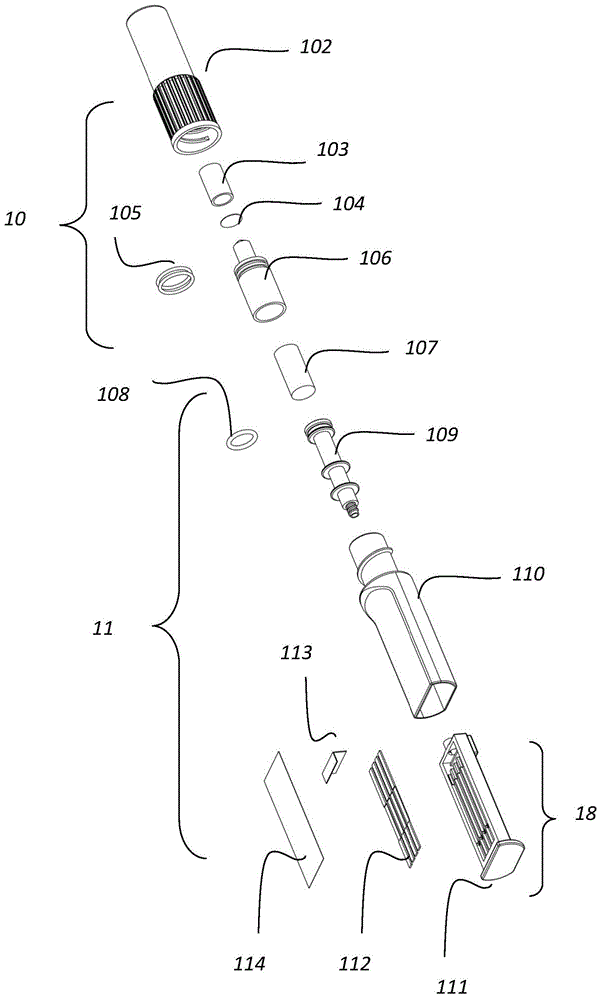
图1是本发明的一个具体实施方式中的接收装置和检测装置的结构分解结构示意图。FIG. 1 is a schematic structural exploded view of a receiving apparatus and a detecting apparatus in a specific embodiment of the present invention.
图2是本发明的一个具体实施方式中的带有测试元件载体的结构示意图。FIG. 2 is a schematic structural diagram of a carrier with a test element in an embodiment of the present invention.
图3是本发明的另外一个具体实施例中带有测试元件载体的结构示意图。FIG. 3 is a schematic structural diagram of a carrier with test elements in another specific embodiment of the present invention.
图4A是本发明一个具体实施方式中测试元件载体组装后,显示引流元件和载体腔的位置配合立体分解示意图。FIG. 4A is a perspective exploded schematic diagram showing the position matching of the drainage element and the carrier cavity after the test element carrier is assembled in an embodiment of the present invention.
图4B是本发明一个具体实施方式中测试元件载体组装后的立体结构示意图。FIG. 4B is a schematic three-dimensional structure diagram of the test element carrier after assembly in a specific embodiment of the present invention.
图5是本发明的一个具体实施例中,收容元件的立体结构示意图。FIG. 5 is a schematic three-dimensional structure diagram of a receiving element in a specific embodiment of the present invention.
图6是本发明一个具体实施方式中收容元件的纵剖面的立体结构图。6 is a perspective structural view of a longitudinal section of a receiving element in an embodiment of the present invention.
图7是本发明一个具体实施方式中载体的背面结构示意图。FIG. 7 is a schematic diagram of a backside structure of a carrier in an embodiment of the present invention.
图8是本发明一个具体实施方式中载体被组装到收容元件的收容腔中的立体结构示意图。8 is a schematic three-dimensional structural diagram of a carrier assembled into a receiving cavity of a receiving element according to an embodiment of the present invention.
图9是本发明一个具体实施方式中,载体被插入到收容结构后的立体部分剖面结构示意图。9 is a schematic diagram of a three-dimensional partial cross-sectional structure after the carrier is inserted into the receiving structure in an embodiment of the present invention.
图10为本发明一个具体实施方式中检测装置的分解结构示意图。FIG. 10 is a schematic diagram of an exploded structure of a detection device in a specific embodiment of the present invention.
图11为本发明的一个具体实施方式中,带有收集器的检测装置的结构示意图。FIG. 11 is a schematic structural diagram of a detection device with a collector in a specific embodiment of the present invention.
图12为本发明的一个具体实施方式中,收集器与测试元件以及引流元件的配合的结构示意图。FIG. 12 is a schematic structural diagram of the cooperation of the collector, the test element and the drainage element in an embodiment of the present invention.
图13是本发明的一个具体实施方式中,接收装置或者接收杯的立体结构示意图。Fig. 13 is a schematic three-dimensional structural diagram of a receiving device or a receiving cup in a specific embodiment of the present invention.
图14是本发明的一个具体实施方式中,接收装置或者接收杯的各个部件的立体分解剖面图。Figure 14 is a perspective exploded cross-sectional view of the various components of the receiving device or the receiving cup in one embodiment of the present invention.
图15是本发明的一个具体实施方式中,接收装置或者接收杯的立体结构剖面图(刺破元件处于初始第一位置)。Fig. 15 is a cross-sectional view of a three-dimensional structure of a receiving device or a receiving cup in a specific embodiment of the present invention (the piercing element is in the initial first position).
图16是本发明的一个具体实施方式中,带有腔体的刺破元件的立体结构示意图。16 is a schematic three-dimensional structural diagram of a puncturing element with a cavity in a specific embodiment of the present invention.
图17是本发明的一个具体实施方式中,刺破元件的剖面结构示意图。FIG. 17 is a schematic cross-sectional structure diagram of a piercing element in an embodiment of the present invention.
图18是本发明的一个具体实施方式中,测试装置插入到接收装置前的剖面结构示意图。FIG. 18 is a schematic cross-sectional structure diagram of a testing device before being inserted into a receiving device according to an embodiment of the present invention.
图19是本发明的一个具体实施方式中,测试装置(吸收元件吸收流体样本)插入到接收装置前的剖面结构示意图(含有处理溶液)。FIG. 19 is a schematic cross-sectional structure diagram (containing a treatment solution) of a testing device (absorber element absorbing fluid sample) before insertion into a receiving device according to an embodiment of the present invention.
图20是本发明的一个具体实施方式中,测试装置插入到接收装置中刺破元件的腔体中,吸收元件被挤压后的剖面结构示意图,刺破元件处于第一初始位置。Figure 20 is a schematic cross-sectional view of the absorbing element after the testing device is inserted into the cavity of the piercing element in the receiving device in a specific embodiment of the present invention, and the piercing element is in the first initial position.
图21是本发明的一个具体实施方式中,测试装置插入到接收装置中刺破元件的腔体中,刺破吸收元件被连接元件从第一位置向第二位置移动的剖面结构示意图(刺破结构刺破了容纳处理液的腔体,并部分进入到腔体中)。Figure 21 is a schematic cross-sectional view of the test device inserted into the cavity of the puncturing element in the receiving device, and the puncturing absorbing element is moved from the first position to the second position by the connecting element in a specific embodiment of the present invention (puncturing The structure pierces the cavity containing the treatment liquid and partially enters the cavity).
图22是本发明的一个具体实施方式中,刺破吸收元件被连接元件从第一位置向第二位置移动的剖面结构示意图(刺破结构的第一腔体被插入到到腔体中,处理液进入到第一腔与流体样本混合后并穿过吸收元件流入到测试元件)。22 is a schematic cross-sectional view of the puncture absorption element being moved from the first position to the second position by the connecting element in a specific embodiment of the present invention (the first cavity of the puncture structure is inserted into the cavity, and the processing The fluid enters the first chamber after mixing with the fluid sample and flows through the absorbent element to the test element).
图23是本发明的一个具体实施方式中的结构原理示意图(移动元件初始位置)。FIG. 23 is a schematic diagram of the structural principle (initial position of the moving element) in a specific embodiment of the present invention.
图24是本发明的一个具体实施方式中的结构原理示意图(移动元件移动,密闭空间气压增高)。Fig. 24 is a schematic diagram of the structural principle in a specific embodiment of the present invention (moving element moves, air pressure in the closed space increases).
图25是本发明的一个具体实施方式中的结构原理示意图(液体流出)。FIG. 25 is a schematic diagram of the structural principle (liquid outflow) in a specific embodiment of the present invention.
详细说明Detailed description
下面对本发明涉及的结构或这些所使用的技术术语做进一步的说明,如果没有特备指明,按照本领域的通用的一般术语进行理解和解释。The structures involved in the present invention or the technical terms used are further described below. If there is no special indication, they should be understood and interpreted according to the general terms commonly used in the art.
检测detect
检测表示化验或测试一种物质或材料是否存在,比如,但并不限于此,化学物质、有机化合物、无机化合物、新陈代谢产物、药物或者药物代谢物、有机组织或有机组织的代谢物、核酸、蛋白质或聚合物。另外,检测表示测试物质或材料的数量。进一步说,化验还表示免疫检测,化学检测、酶检测等。Detection means assaying or testing for the presence of a substance or material such as, but not limited to, chemicals, organic compounds, inorganic compounds, metabolites, drugs or drug metabolites, organic tissue or metabolites of organic tissue, nucleic acids, protein or polymer. In addition, detection refers to the quantity of a test substance or material. Further, the assay also means immunoassay, chemical assay, enzymatic assay, and the like.
样本sample
本发明的检测装置或者收集的样品包括生物液体(例如病例液体或者临床样品)。液体样品或者流体样本,可以来源于固态或者半固态的样品,包括排泄物,生物组织和食品样品。利用任何适当的方法可以将固态或半固态的样品转化成液体样品,例如混合、捣碎、浸软、孵育、溶解或在合适的溶液中(例如水,磷酸盐溶液或其他缓冲溶液)利用酶解作用消化固体样品。“生物样品”包括来源于动物,植物和食品样品,例如包括来源于人或动物的尿液,唾液,血及其成分,脊髓液、阴道分泌物,精子,粪便,汗液,分泌物,组织,器官,瘤,组织和器官的培养物,细胞培养物和介质。优选生物样品是尿,优选的,生物样品是唾液。食品样品包括食品加工的物质,最终产品,肉,干酪,酒,牛奶和饮用水。植物样品包括源于任何植物,植物组织,植物细胞培养物和介质。“环境样品”来源于环境(例如,来自于湖或者其他水体的液体样品,污水样品,土质样品,地下水,海水和废液样品)。环境样品还可包括污水或者其他废水。Detection devices or collected samples of the present invention include biological fluids (eg, patient fluids or clinical samples). Liquid samples or fluid samples can be derived from solid or semi-solid samples, including excreta, biological tissue and food samples. A solid or semi-solid sample can be converted to a liquid sample by any suitable method, such as mixing, mashing, macerating, incubating, dissolving or using enzymes in a suitable solution (eg water, phosphate solution or other buffer solution) Digestion of solid samples. "Biological samples" include animal, plant and food samples, including, for example, urine, saliva, blood and components thereof, spinal fluid, vaginal secretions, sperm, feces, sweat, secretions, tissues, of human or animal origin, Organs, tumors, tissues and organ cultures, cell cultures and media. Preferably the biological sample is urine, preferably the biological sample is saliva. Food samples include food processing substances, final products, meat, cheese, wine, milk and drinking water. Plant samples include those derived from any plant, plant tissue, plant cell culture and media. "Environmental samples" are derived from the environment (eg, liquid samples from lakes or other bodies of water, sewage samples, soil samples, groundwater, seawater, and waste liquid samples). Environmental samples may also include sewage or other waste water.
利用本发明合适的检测元件或者测试元件,可以检测任何被分析物。优选利用本发明检测唾液、尿液中的毒品小分子。当然,利用本发明的收集器可以收集以上任何形式的样本,无论开始是固态的,还是液态的,只要这些液体或者液体样本能够被吸收元件吸收。这里的吸收元件107一般都是采用吸水材料制备,一开始是干的,通过吸收元件材质的毛细或者其它特性,能够吸收液体样本或者流体样本,让流体样本保持在吸收元件中。吸收材料可以是任何能够吸收液体材质,例如海绵、滤纸,聚酯纤维、凝胶、无纺布、棉、聚酯膜薄、纱线等等。当然吸收元件并不一定是具有吸水性质的材料制备,可以是非吸水材料制备,但是在吸收元件上具有孔、螺纹、洞穴,可以在这些结构上收集样本,这些样本一般是固体或者半固体样本,这些样本被填充在螺纹之间、洞,或者孔中,从而收集样本。当然,可选的,吸收元件可以是由一些非吸水的纤维,毛发组成,用这些材料来刮取一个固态、半固态或者液体样本,让这些样本被保持在吸收元件上。Any analyte can be detected using a suitable detection element or test element of the present invention. Preferably, the present invention is used to detect small drug molecules in saliva and urine. Of course, any of the above forms of samples can be collected using the collector of the present invention, whether initially solid or liquid, as long as these liquids or liquid samples can be absorbed by the absorbing element. The
下游和上游downstream and upstream
下游或者上游是对于液体流动方向来划分的,一般液体或者流体从上游流到下游区域。位于下游区域接受来自上游区域的液体,液体也可以沿着上游区域流到下游区域。这里一般是按照液体流动的方向还划分的,例如,利用毛细力促使液体流动的一些材料上,液体可以克服重力而向重力相反的方向流动,这个时候,还是按照液体的流动方向来划分上游和下游。例如,在本发明的检测装置102中,当吸收元件吸收有流体样本或者液体样本后,流体可以从吸收元件107流动到测试元件112的加样区域1121,这个时候液体在加样区1121向吸收区1123的流动就是从上游流动到下游去,在流通的过程中,经过测试区1122,在测试区域上有检测区域1126和检测结果控制区域1125。测试区域可以是聚酯纤维薄膜,加样区可以是玻璃纤维。这个时候,吸收元件107处于测试元件加样区的上游。Downstream or upstream is divided for the direction of liquid flow, generally the liquid or fluid flows from the upstream to the downstream area. The downstream region receives liquid from the upstream region, and the liquid can also flow along the upstream region to the downstream region. This is generally divided according to the direction of liquid flow. For example, on some materials that use capillary force to promote liquid flow, the liquid can overcome gravity and flow in the opposite direction of gravity. At this time, the upstream and downstream are still divided according to the flow direction of the liquid. downstream. For example, in the
当然,这里的上游和下游也可以是物体运动的轨迹或者方向,并不是液体流通的方向。例如如图19-22中的刺破元件从上游被移动到下游,此时容纳处理液的腔体基本处于静止不动的状态,而刺破元件的移动就是从上到下的移动并逐步靠近容纳处理液的腔,例如刺破容纳处理液的密封腔,继续进入该密封腔体中。刺破移动的方向和处理液或者流体样本可以是相反的方向,可以全部过程的相反,也可以是部分过程的相反。例如刺破元件从上向下移动,而处理液流体沿着刺破元件的运动的方向相反的方向流动。在比如,刺破元件从上到下的移动,而流体样本一开始是从上向下流动(在刺破元件中),随着刺破元件的继续移动,流体样本和处理液混合后,可以沿着与刺破元件运动相反的方向流动。Of course, the upstream and downstream here can also be the trajectory or direction of the movement of the object, not the direction of liquid flow. For example, as shown in Figures 19-22, the piercing element is moved from upstream to downstream. At this time, the cavity containing the treatment liquid is basically in a stationary state, and the movement of the piercing element is from top to bottom and gradually approaches. The cavity containing the processing liquid, for example, puncturing the sealed cavity containing the processing liquid, continues to enter the sealed cavity. The direction of the piercing movement and the processing liquid or the fluid sample can be the opposite direction, the reverse of the whole process, or the reverse of a part of the process. For example, the piercing element moves from top to bottom, while the treatment fluid flows in a direction opposite to the direction of movement of the piercing element. For example, when the piercing element moves from top to bottom, and the fluid sample initially flows from top to bottom (in the piercing element), as the piercing element continues to move, the fluid sample and the treatment fluid are mixed and can be Flow in the opposite direction to the movement of the piercing element.
气体连通或者液体连通Gas communication or liquid communication
气体连通或者液体连通是指液体或者气体能够从一个地方流动到另一个地方,流动的过程中可能经过一些物理的结构起到引导作用。所谓经过物理的结构一般是指液体经过这些物理的结构的表面,或者这些结构的内部的空间而被动或者主动流到另外一个地方,被动一般是收到外力而引起的流动,例如毛细作用下的流动,气压作用等。这里的流动也可以是液体或者气体因为自身作用(重力或者压力),也可以是被动的流动,气压作用的流体可以是顺势的流动,也可以是反方向的流动,也可以是气压的作用下促使流体从一个位置流到另一个位置。这里的连通并不表示一定需要液体或者气体存在,仅仅在一些情况下表明两个物体之间的连接关系或者状态,如果有液体存在,可以从一个物体流动到另一个物体上。这里是指两个物体连接的状态,相反,如果两个物体之间没有液体连通或者气体连通状态,如果有液体在一个物体中或者上,液体不能流动到另外一个物体中或者上,这样的状态为非连通,非液体或者气体连通的状态。Gas communication or liquid communication means that liquid or gas can flow from one place to another, and may pass through some physical structures to guide the flow. The so-called physical structure generally refers to the liquid passing through the surface of these physical structures, or the internal space of these structures and passively or actively flowing to another place. Passive is generally the flow caused by external force, such as capillary action. flow, air pressure, etc. The flow here can also be a liquid or a gas due to its own action (gravity or pressure), or a passive flow. The fluid under the action of air pressure can be a flow in the homeopathic direction, or a flow in the opposite direction, or it can be under the action of air pressure. Causes fluid to flow from one location to another. The connection here does not necessarily mean the existence of liquid or gas, but only indicates the connection relationship or state between two objects in some cases. If there is liquid, it can flow from one object to another. This refers to the state in which two objects are connected. On the contrary, if there is no liquid communication or gas communication between the two objects, if there is liquid in or on one object, the liquid cannot flow into or on the other object, such a state It is a state of non-communication, non-liquid or gas communication.
可拆卸的组合Detachable combination
可拆卸式的组合,是指两个部件之间的连接关系处于几个不同的状态或者位置关系,例如当是两个物理意义上部件的时候,一开始可以是分开的,当在合适的第一情况下连接或者组合在一起,当在合适的第二情况下,可以让两个部件分开,这种分开是物理意义上的空间分开而不接触。或者,两个部件一开始是组合在一起,当在合适的情况下,可以让两个部件形成物理意义上的空间分开。再或者,两个物体一开始是分开的,需要的时候组合在一起完成某种功能,然后再分开,或者后来再次为了某种目的再次组合在一起。总之,两者组合在一起或者两者之间的分开是可以容易的进行,这种组合在一起或者分开是可以重复多次循环,当然,也可以是一次性的组合和分开。另外,可以是两个部件之间可拆卸的组合,也可是三个或者三个以上部件之间两两可拆卸的组合。例如,具有第一、第二和第三部件,第一部件和第二部件可拆卸的组合,第二部件和第三部件也可以是可拆卸式的组合,第一部件和第三部件也可以可拆卸的组合或者分离。另外,组合的方式可以是两个物体本身来可拆卸,也可以通过另外的物体间接的组合。在这里,吸收元件107可以和测试元件112可拆卸的组合,这种可拆卸的组合是可以直接的,也是可以间接,下面会有详细的描述。带有测试元件的载体111和收容元件的腔体110也是一种可拆卸的组合,这样,他们的组合在一起就形成了检测装置,但是拆开后,可以各自具有各自的用途。在本发明中,吸收元件与测试元件分开后,吸收元件可以单独进行灭菌,例如高温、X射线、辐射灭菌等方式,等灭菌完成后,再和测试元件组合在一起。这样,可以让来自吸收元件与测试元件形成流体连通,从而来自吸收元件的液体可以从吸收元件流到测试元件上。A detachable combination means that the connection relationship between the two components is in several different states or positional relationships. For example, when there are two physical components, they can be separated at the beginning. In one case connected or combined together, when in a suitable second case, the two parts may be separated, this separation being physically separated in space without touching. Alternatively, the two parts are initially combined, and when appropriate, the two parts can be physically separated. Or, the two objects are initially separate, combined when needed to perform a function, then separated, or later combined again for some purpose. In a word, the combination of the two or the separation between the two can be easily carried out, and the combination or separation can be repeated for multiple cycles, of course, it can also be a one-time combination and separation. In addition, it may be a detachable combination of two components, or a detachable combination of three or more components. For example, there are first, second and third parts, the first part and the second part are detachable combination, the second part and the third part can also be a detachable combination, the first part and the third part can also be Detachable combination or separation. In addition, the combination method can be that the two objects can be disassembled by themselves, or they can be indirectly combined through another object. Here, the absorbing
测试元件test element
这里所谓的“测试元件”是指可以检测样本或者样品是否含有感兴趣的被分析物质的元件都可以称之为测试元件,这种检测无论是基于何种技术原理,免疫学、化学、电学、光学,分子学,核酸、物理学等都可以。测试元件可以选用横向流动的检测试纸条,它可检测多种被分析物。当然,其他合适的测试元件也可以运用在本发明中。The so-called "test element" here refers to the element that can detect the sample or whether the sample contains the analyte of interest. It can be called the test element. This detection is based on whatever technical principle, immunology, chemistry, electricity, Optical, molecular, nucleic acid, physics, etc. The test element can be selected as a lateral flow test strip, which can detect a variety of analytes. Of course, other suitable test elements can also be used in the present invention.
各种测试元件可以被组合在一起运用到本发明中。一种形式是检测试纸。用于分析样本中的被分析物(如毒品或表明身体状况的代谢物)的检测试纸可以是各种形式,如免疫测定或化学分析的形式。检测试纸可以采用非竞争法或竞争法的分析模式。检测试纸一般包含一具有样本加样区的吸水材料,试剂区和测试区。加流体或者液体样本至样本加样区,通过毛细管作用流到试剂区。在试剂区,如果存在被分析物,样本与试剂结合。然后样本继续流动到检测区。另一些试剂,如与被分析物特异性结合的分子被固定在检测区。这些试剂与样本中的被分析物(如果存在)反应并将被分析物结合在该区,或者与试剂区的某一个试剂结合。用于显示检测信号的标记物存在与试剂区或分离的标记区。Various test elements can be used in combination with the present invention. One form is test strips. Test strips for analysis of analytes (eg, drugs or metabolites indicative of medical conditions) in a sample can be in various formats, such as in the form of immunoassays or chemical assays. The test strips can be analyzed in a non-competitive or competitive mode. The test strip generally includes a water-absorbing material with a sample application area, a reagent area and a test area. Add fluid or liquid sample to the sample application area and flow to the reagent area by capillary action. In the reagent area, the sample binds to the reagent if the analyte is present. The sample then continues to flow to the detection zone. Other reagents, such as molecules that specifically bind to the analyte, are immobilized in the detection zone. These reagents react with the analyte (if present) in the sample and bind the analyte in this zone, or bind to one of the reagents in the reagent zone. The label used to display the detection signal is present in the reagent zone or separate label zone.
典型的非竞争法分析模式是如果样本中含有被分析物,信号就会产生,如果不包含被分析物,就不产生信号。在竞争法中,如果被分析物不存在于样本中,信号产生,如果存在被分析物,则不产生信号。In a typical non-competitive assay mode, a signal is generated if the analyte is present in the sample, and no signal is generated if the analyte is not present. In the competition method, a signal is generated if the analyte is not present in the sample, and no signal is generated if the analyte is present.
测试元件可以是检测试纸,可以选用吸水或不吸水的材料。检测试纸可包括多种材料用于液体样本传递。其中一种检测试纸的材料可覆盖在另一种材料上,如滤纸覆盖在硝酸纤维素膜上。检测试纸的一个区可以选用一种或多种材料,而另一区选用其他不同的一种或多种材料。检测试纸可以被黏附在某种支持物或者硬质表面用于提高拿捏检测试纸的强度。The test element can be a test paper, and a material that absorbs or does not absorb water can be selected. Test strips can include a variety of materials for liquid sample transfer. One of the test paper materials can be overlaid on another material, such as filter paper overlaid on a nitrocellulose membrane. One area of the test strip can be selected from one or more materials, while the other area can be selected from other different materials or materials. Test strips can be adhered to a support or hard surface to improve the strength of the test strips.
被分析物通过信号发生系统而被检测到,如利用与本分析物发生特异性反应的一种或多种酶,利用如前述将特异结合物质固定在检测试纸上的方法,将一种或多种信号发生系统的组合物固定在检测试纸的被分析物检测区。产生信号的物质可在加样区,试剂区,或检测区,或整个检测试纸上,该物质可以充满检测试纸的一种或多种材料上。将含有信号物的溶液加到试纸的表面或将试纸的一种或多种材料浸没在含信号物的溶液中。使加入含信号物溶液的试纸干燥。The analyte is detected by a signal generating system, such as using one or more enzymes that specifically react with the analyte, using the method of immobilizing the specific binding substance on the detection test paper as described above, and combining one or more enzymes. The composition of the signal generating system is immobilized on the analyte detection area of the test strip. The signal-generating substance may be in the sample application area, the reagent area, or the detection area, or the entire test strip, and the substance may impregnate one or more materials of the test strip. The signal-containing solution is added to the surface of the test paper or one or more materials of the test paper are immersed in the signal-containing solution. The test paper to which the signal containing solution was added was allowed to dry.
检测试纸的各个区可以按以下方式排列:加样区,试剂区,检测区,控制区,确定样本是否掺假区,液体样本吸收区。控制区位于检测区之后。所有的区可以被安排在只用一种材料的一条试纸上。也可是不同区采用不同的材料。各个区可以直接和液体样本接触,或不同的区依据液体样本流动的方向排列,将各区的末端与另一区的前端相连并交叠。所用的材料可以是吸水性较好的材料如滤纸,玻纤或者硝酸纤维素膜等。检测试纸也可以采用其他形式。The various areas of the test strip can be arranged in the following ways: sample addition area, reagent area, detection area, control area, determination of whether the sample is adulterated or not, and liquid sample absorption area. The control area is located after the detection area. All zones can be arranged on a strip of test strips using only one material. It is also possible to use different materials for different zones. Each zone can be in direct contact with the liquid sample, or different zones can be arranged according to the direction of the liquid sample flow, and the end of each zone can be connected and overlapped with the front end of another zone. The material used can be a material with better water absorption such as filter paper, glass fiber or nitrocellulose membrane. Test strips can also take other forms.
一般常用的试剂条为硝酸纤维素膜试剂条,即检测区域包括硝酸纤维素膜(NC),在硝酸纤维素膜上固定特异结合分子来显示检测的结果;还可以是醋酸纤维素膜或尼龙膜等等。例如如下一些专利描述的试剂条或含有试剂条的装置:US 4857453;US 5073484;US5119831;US 5185127;US 5275785;US 5416000;US 5504013;US 5602040;US 5622871;US5654162;US 5656503;US 5686315;US 5766961;US 5770460;US 5916815;US 5976895;US6248598;US 6140136;US 6187269;US 6187598;US 6228660;US 6235241;US 6306642;US6352862;US 6372515;US 6379620;和US 6403383。以上专利文献所公开的测试条以及带有测试条的类似装置都可以被运用到本发明的测试元件或者检测装置中进行被分析物质的检测,例如样本中被分析物质的检测。The commonly used reagent strips are nitrocellulose membrane reagent strips, that is, the detection area includes a nitrocellulose membrane (NC), and specific binding molecules are immobilized on the nitrocellulose membrane to display the detection results; it can also be a cellulose acetate membrane or nylon film, etc. For example, the following patents describe reagent strips or devices containing reagent strips: US 4,857,453; US 5,073,484; US 5,119,831; US 5,185,127; US 5,275,785; US 5,766,961; US 5,770,460; US 5,916,815; US 5,976,895; US 6,248,598; US 6,140,136; The test strips disclosed in the above patent documents and similar devices with test strips can be applied to the test element or detection device of the present invention to detect the analyte, such as the detection of the analyte in the sample.
运用到本发明的检测试剂条可以是通常所说的横向侧流试剂条(Lateral flowtest strip),这些检测试剂条的具体结构和检测原理在现有技术中是本领域一般技术人员公知的技术。普通的检测试剂条(图2),包括样本收集区域或者是加样区1121,标记区域(未显示),检测区域1122和吸水区域1123,样本收集区域包括样本接受垫,标记区域包括标记垫,吸水区域可以包括吸水垫,其中检测区域上包括能检测是否含有被分析物质的必要化学物质,例如免疫试剂或者酶化学试剂。一般常用的检测试剂条为硝酸纤维素膜试剂条,即检测区域1122包括硝酸纤维素膜,在硝酸纤维素膜上固定特异结合分子来显示检测的结果区域;还可以是醋酸纤维素膜或尼龙膜等等;当然,在检测区域的下游还可以包括检测结果控制区域1125,通常,控制区域和检测区域上以横线1126的形式出现,为检测线1126或者控制线1125。这样的检测试剂条是传统的试剂条,当然,也可是其它利用毛细作用进行检测的其它类型的试剂条。另外,一般检测试剂条上带有干化学试剂成分,例如固定的抗体或者其他试剂,当遇到液体后,液体随着毛细作用沿着试剂条流动,随着流动,让干的试剂成分溶解于液体,从而到下一个区域处理在该区的干试剂发生反应,从而进行必要的检测。液体流动主要通过毛细作用进行的。在这里都可以被运用到本发明的检测装置中,或者被设置在检测腔中与液体样本接触,或者用来检测进入检测腔中的液体样本中被分析物质是否存在或者存在的数量。The detection reagent strips used in the present invention may be so-called lateral flow test strips. The specific structures and detection principles of these detection reagent strips are well known to those skilled in the art in the prior art. A common detection reagent strip (Fig. 2) includes a sample collection area or a
除了上述测试条或者横向流动测试条本身被用来与液体样本接触来测试液体样本中是否含有被分析物质外。Except that the above-mentioned test strip or the lateral flow test strip itself is used to contact the liquid sample to test whether the liquid sample contains the analyte.
本发明的测试元件本身就可以作为检测装置来检测样本中被分析物质,所以,这里检测装置本身就等同于测试元件。例如流体样本被处理液混合后,直接用测试元件进行检测。下面会有具体的描述,当在描述接收装置来处理流体样本的时候,测试元件可以单独用来检测。The test element of the present invention itself can be used as a detection device to detect the analyte in the sample, so the detection device itself is equivalent to the test element here. For example, after the fluid sample is mixed with the treatment liquid, it is directly tested with the test element. As will be described in detail below, the test element may be used alone for detection while describing the receiving device for processing a fluid sample.
载体元件carrier element
在一些具体的方式中,测试元件也可以被设置在一些载体元件上,这样载体元件含有测试元件,完成流体样本中被分析物质的简称和化验。因此,在一些方式中,检测装置包括载体,载体上设置有测试元件。如图2所示,例如一些载体111上,一般载体上具有一个或者多个凹槽1115,测试元件位于凹槽1115中,载体一般具有正面和背面,测试元件位于载体的正面上。凹槽的个数不做限制,一般一个测试元件位于一个凹槽中,通常一个测试元件可以对样本中一个被分析物进行检测,当然一个测试元件可以同时检测一个或者多个,一种或者多种被分析物质。在一些方式中,载体111包括一个具有开口的腔体1116,在靠近凹槽区域具有一个凹陷区域,形成腔体1116,腔体的开口1114的水平位置和设置测试元件的凹槽区域底部基本处于同一个平面。在一些方式中,凹槽的长度小于测试元件的长度,这样当测试元件被设置在凹槽中的时候,测试元件的部分区域悬在腔体1116的开口1114上(如图4A所示)。该腔体1116包括一个分割元件,该分割元件把腔体1116分割为第一区域和第二区域,分割结构类似一款挡板1119,该挡板位于载体上进液通道入口1117的前面,但是该挡板并不横穿整个腔体,而是在腔体的两侧预留缺口(未显示),既档板的宽度小于腔体的宽度。这样当通过液体流入口1117流入的液体,可以通过缺口流到腔体的第二区域中。当然,也可以是挡板1119的宽度与腔体的宽度一样,挡板的高度小于腔体的深度。这样,多余的液体可以漫过挡板流入到第二区域中进行存储。在一些方式中,挡板1119把腔体1116分为挡板1119与导流通道的入口1117之间的第一区域1122,剩下的则为腔体的第二区域1120。第二区域主要是作为流体样本缓冲区域,当多余的液体流入到腔体1116中的时候,除了一部分流入到测试元件中,另外多余的部分可以流入到第二区域1120中。腔体一般的形状为长方体,当然可以是其它形状,例如正方体、圆柱体。在一些方式中,载体111上还设置导流元件113,该导游元件113连接进液口1117和测试元件,或者测试元件的加样区1121。例如,导流元件一部分1131是设置在挡板1119和进液口1117之间的第一区域,另一部分1133是搭接或者覆盖在部分加样区域1121上,这样从导流通道的入口或者进液口1117的液体一旦进入到载体中,就直接接触导流元件,从而通过导流元件把液体导流到测试元件上。In some specific manners, the test elements can also be arranged on some carrier elements, such that the carrier elements contain the test elements to complete the abbreviation and assay of the analyte in the fluid sample. Thus, in some approaches, the detection device includes a carrier on which the test element is disposed. As shown in FIG. 2, for example, some
在进液口1117前设置挡板或者分割元件或者分割结构,主要是防止如果通过进液口流入的液体样本量很大的时候或者流入的速度很快,会造成对引流元件的冲击,可以起到让引流元件不被冲走或者不被冲击变形,这样可以到稳定的导流作用,引流元件一般是吸水材料,例如玻璃纤维薄片的样式。如果有多余的样本,可以流入到腔体1116的第二区域,第二区域起到分流的作用,因为太多的液体样本通过引流元件113流到加样区会引起测试条的“洪流”,所以这样减少了洪流现象。另外,导游元件113也是起到缓解流体冲击的作用,因为进液口1117一旦有液体进来,首先接触的是导流元件113,导流元件也是可以起到阻碍液体的作用,从而延缓液体进入到腔体的第二区域。如果操作的不同方式或者插入到刺破元件的力度不同,有时候会让流入到载体的液体速度快,冲击力大,引流扮演减弱冲击力的作用,不至于让液体类似“喷射”的形式流入到腔体中。如果液体量比较大,则流到第二区域去,流入的方式可以通过挡板与腔体之间的缺口,或者直接漫过挡板流入到第二区域。另外导流元件可以引导流体流动到导流元件的覆盖在测试条的区域上,这样,让多个测试条获得的液体样本的量基本一样多。挡板1119与进液口1117之间留有一个狭缝,就是让导流元件的部分位于挡板和进液口之间,一是导流作用,另外挡板为了防止导流元件113的位置变化,导流元件一般是柔性的滤纸,玻璃纤维等材料,在进液口的液体冲击下,如果发生了位置的变化,这样就会影响到引导的液体不一定会均匀分配到多个测试元件上。在如图2和图3以及图4A中导流元件的方式,更加增强导流元件113的稳定性。如果有多余的样本,就会流到位于加样区域1121的下面的凹陷区域汇集,从而避过多的样本流到测试条112上去。当然,另外的形式的导流元件,例如“T”,“L”任何形式都可以。以上都是本发明的一些优选的方案,当然没有凹陷区或者腔体、没有档板,没有导流元件,只要进液口1117与测试元件保持流体连通,也是可以实现样本中被分析物质的测试(图2)。为了更好的减少液体的冲击,可以让第一区域狭窄,仅仅可以让导流元件插入到该狭小区域中,让应有元件的一端1131几乎覆盖在流体入口1117上,而分割板则起到让引流元件固定位置的作用,减少也对引流元件的冲击变形的影响;话句话说,可以让第一区的宽度与流体元件131的厚度相当,这样也通用可以起到固定流体元件的作用。A baffle plate or a dividing element or a dividing structure is provided in front of the
在一些方式中,当测试元件设置在载体的凹槽中后,再在载体上覆盖一层透明或者部分透明的薄膜114,一是密封载体的凹槽区域和腔体的开口,另外透明的薄膜容易观察最终检测区域上测试结果。透明的薄膜也可以是透明的塑料片,仅仅在测试区1122域透明就可以了。采用薄膜的形式覆盖整个载体的上面,基本让测试元件112和腔体1116处于一个密闭的空间里,这样防止测试元件在包装运输过程中潮湿而影响测试的性能。这样,当通过导入通道1115导入的液体进入到载体中,例如进入到载体上的腔体1116中,这样在腔体或者载体里由于液体的进入而占据一定的空间,从而让本来存在的空气受到压缩,不利于液体的顺利进入。所以,在一些方式中,在腔1116的边缘具有一些缺口1118,11181,等薄膜覆盖上的时候,就形成了通孔,这样多余的气体或者空气被排除到载体外,保持了载体内的气压与外界气压一样,方便液体容易地进入到载体中来。这个在后面会详细说明。在一些优选的方式中,例如在收集器的吸收元件107被插入到刺破元件106的腔体中的时候,让刺破元件的腔体可以与载体上的腔体1116形成流体连通,这样,刺破元件的腔体与外界相通,保持刺破元件腔体内与外界的气压一致,或者差异不大,甚至相同或者几乎实质相同。In some ways, after the test element is arranged in the groove of the carrier, a transparent or partially
收容元件housing element
在一些方式中,如果直接让载体和吸收元件连接,在操作的时候,仍然不是很方便和安全,是因为不是专业实验室具有专门培训的人进行操作,使用者都是没有多少检测经验的人进行,在收集样本或者操作中,显得不是很友好,而且对测试条具有损坏的可能,例如手握住的地方不同。手指可能会压迫测试条,或者碰触到测试条,这样可能对测试条具有负面的影响,影响最终的检测结果。另外,该吸收元件需要插入到接收装置中对吸收元件进行挤压,同时还需要用力来推动刺破元件进行移动,另外释放溶液腔里的液体与样本进行混合等系列动作,如果仅仅依靠载体本身来完成,虽然可以完成,但是仍然不够安全,操作者需要特别的小心。所以,一方面,在一些方式中,所述的检测装置还包括收容元件110,该收容元件包括收容腔1104,该收容腔腔用来收容带有测试元件的载体18。所述的收容腔与载体的整体形状相似。在一个具体实施方式中,本发明的载体呈长方体的样式,收容腔1104也为大体长方形的,也具有上面1102或者背面1107。在一些方式中,收容腔的上面1102为透明,可以透过透明部分读取载体上测试元件的检测结果,例如用肉眼,或者扫描设备等电子仪器进行读取。In some ways, if the carrier and the absorbing element are directly connected, it is still not very convenient and safe to operate, because it is not operated by a professional laboratory with special training, and the users are all people with little testing experience. It is not very friendly during sample collection or operation, and there is a possibility of damage to the test strip, such as different places where the hand is held. Fingers may press on the test strip, or touch the test strip, which may negatively affect the test strip and affect the final test result. In addition, the absorbing element needs to be inserted into the receiving device to squeeze the absorbing element, and at the same time, it needs to push the piercing element to move, and release the liquid in the solution chamber to mix with the sample and other series of actions, if only rely on the carrier itself Although it can be done, it is still not safe enough, and the operator needs special care. Therefore, on the one hand, in some manners, the detection device further includes a receiving
在一些方式中,方便载体顺利装配或者插入到收容腔1104中,在收容内设置滑道,该滑道有两组滑道组成,该其中一组滑道45,1110设置在收容腔侧壁上,在另一个侧壁上也设置对应的滑道(未显示)。这样载体的两侧的侧面182,181作为滑轨。这样载体可以稳定的,或者相对固定的安装在收容腔的固定位置。在装配的时候,为了让载体的上面(带有测试元件的一面)面对收容腔的上面1102,在载体上设置限位结构,防止在装配的时候,载体的上面面对收容腔的下面1107。一限位结构例如限位块1112位于载体的背面,并且位于载体的腔体1116的正下方,或者位于液体导入通道115的下方。限位块1112位于滑轨之间,滑轨依然在限位块两端1822,1811穿过。一般,从液体导入通道的一端插入到收容腔中。收容腔的滑道45和滑道1110之间的宽度与载体的厚度或者高度相等或者稍微大于厚度。其中,一个滑道采用“「”的形式设置,例如如图8和9所示,在收容腔侧壁上的一个滑道采用这样的方式设计,一条边1109与侧边平行,另一条边1108和收容腔的侧壁垂直,对应的收容腔的另一个侧壁也同样采用这样的结构。这样,实际上,滑道结构的上滑道45(实际上是一对)和下滑道1110(也是一对,另外的收容腔的侧壁没有显示)在收容腔里限定了不同的宽度,这样当载体插入到收容腔的时候,如果载体正面(薄膜114覆盖的一面)面对收容腔的上面1102,则载体的侧面1811和1822作为滑轨的结构接触滑道1110进入到收容腔中。如果方向相反,则则载体的侧面1811和1822作为滑轨的结构接触滑道45的结构,由于滑道45的结构之间的距离小于载体的宽度,则不能被插入到收容腔中,从而只能让载体的上面对应收容腔的上面的方向插入,反之则不能进入收容腔中。而限位块的存在也可以更方便的识别载体的正反面。In some ways, it is convenient for the carrier to be smoothly assembled or inserted into the receiving
所以,在一些优选的方式中,带有测试元件的载体18被设置在容纳载体的腔体11004中,而带有吸收元件107的收集器可以直接与载体连接。例如吸收元件为圆柱形的海绵,该吸收元件通过连接杆109与载体111连接,例如可拆卸的连接在一起。在一些方式中,连接杆109包括一个通道或者管道12(图11),该管道12和载体111上的进液口1117流体连通,这样当吸收元件107被压缩后,液体样本可以通过连接杆的管道流入到载体111的腔体中1106,从而按照上面描述的方式进行被分析物质的分析。样本收集器109可以通过不带吸收元件的一端1093与载体18的带有进液口的管道1115连接,形成液体连通。当然,收集器也可以和腔体1104形成流体连通,而且也是可拆卸的连接,然后腔体1104与连接管道1115形成流体连通,这样也是可以。总之,吸收元件收集液体样本后,可以让流体样本,或者与流体样本混合的处理液通过通道或者流路,流到测试元件上就可以了。当然让吸收元件与载体或者与腔体110可拆卸的组合,也是方便让吸收元件进行单独的灭菌,例如本申请人的美国专利,专利号US10,05,146中描述的吸收原价与测试元件绑定在一起,不能分离,从而不容易进行分别处理,增加了难度。Therefore, in some preferred ways, the
在一些方式中,限位块1112内部含有设置有载体的腔1116,用来收容流体样本和引流元件113。这样,由于载体上设置用于容纳测试元件的凹槽1110,1114,11123,11124的深度比较浅,而载体上的腔体1116的体积比较大,足以容纳来自导入通道流进的液体。所以,在一些方式中,载体上的腔1116位于限位块1112内部。In some ways, the limiting
在一些方式中,收容腔1104的开口1103和载体的末端尾部结构183匹配,也可以起到限制正反面的作用。例如,收容腔的开口110设计为“D”,则载体末端尾部结构183也设计为“D”。当然,其它任何的结构都可以实现正反面的功能。In some ways, the
在一些方式中,收容腔包括连接元件1101,该连接元件是收容腔一端段的延伸段。在收容腔和连接元件之间具有孔11011。当载体被插入到收容腔中,则导入通道1115位于孔11011的附近,而连接元件1101为管状结构的时候,用于让收集器的连接杆一端(例如带有螺纹的一端)插入到连接元件,同时穿过孔11011和导入通道1115连接(如图10,18-19所示)。收集器包括吸收元件107,用于收取样本,例如流体样本。与收集器里连接连接杆109,连接杆里设置通道12(如图18)。这样连接杆内的通道的一端与吸收元件流体连通,另一端和导入通道1115连接,从而经过吸收元件的液体可以通过连接杆内的转运通道12流到导入通道,从而进入到载体的腔体1116中,被引流元件引导到测试元件上。In some embodiments, the receiving cavity includes a connecting
在一些方式中,连接杆109包括凸起结构1091,1092,该凸起结构与连接元件1101的内壁接触,主要是限定了连接杆能够准确的对准导入通道1115的开口,并进行连接。这里的连接杆一端1093和导入通道1115连接的方式可以是任何合适的方式,卡接,螺纹连接,活塞式的连接。In some ways, the connecting
在一些方式中,吸收元件107与测试元件可拆卸式的连接,表示在一开始,可以各自制造,在需要使用的时候,在组装在一起进行使用。这里的主要优势在于,吸收元件,当需要伸入口中吸取唾液样本的时候,吸收元件需要预先进行消毒灭菌,例如高温消毒,辐射消毒。这样,如果测试元件与吸收器一开始就连接在一起,则测试元件上也一起和吸收元件一起消毒,而测试元件上处理有一些化学或者生物物种,这些消毒方式可能会损坏测试元件上的物质的活性,从而最终不能完成正确的测试。例如,测试元件处理有抗体或者抗原,高温消毒造成抗体变性而丧失结合能力,如果测试元件上处理的一些物质,高温会引起挥发而减少,则也会对测试元件的监测性能造成不利影响。另外,可拆卸的方式也方便运输,载体和取样器可以单独包装,等需要的时候,则在组装在一起。这也增加了使用的方便性。在制造的时候,可以分别制造,然后进行单独组装,也可以把各个部件分别制造,然后运输到另外的地方进行组装为完成的产品(如图10-11所示)。图11所示的仅仅是本发明的一个优选的实施方式,可以缺少容纳载体的腔体,也可以缺少导流元件,也可以缺少连接杆等等。In some ways, the absorbing
当然,在一个方式中,当带有测试元件112的载体111被收容元件110组装后,让收集器的连接杆109与载体111组装后,形成一个最终的检测装置,如图11所示。在一些方式中,通过连接杆凸起结构1091,1092与连接元件1101的内壁11012配合,可以增加连接杆的强度或者刚性,以至于在用吸收元件来采集样本的时候,不至于引起连接杆109的折断。另外,这些凸起环状结构也可以让连接杆位于连接元件的中轴线位置,这样,方便让连接杆的一端准确的与载体上的导入通道1115对齐,从而在装配和组装的时候,形成流体连通。Of course, in one way, after the
在一些方式中,连接吸收元件的连接杆的一端具有膨大的部分,吸收元件被设置在膨大的部分上,一般吸收元件的横切面大于连接杆的横切面。膨大的部分可以是圆盘形状805,吸收元件被胶水粘接在圆盘的表面上。这个时候,设置在连接杆内的通道12连接了吸收元件和输入通道1115,从而流体连通了载体上的腔体1116,从而也就流体连通了载体上的测试元元件。在一些方式中,圆盘状上设置弹性密封圈108,用于让吸收元件107处于一个密封的腔体中,防止挤压后的流体样本外流。In some ways, one end of the connecting rod connecting the absorbing element has an enlarged portion, the absorbing element is disposed on the enlarged portion, and generally the cross-section of the absorbing element is larger than the cross-section of the connecting rod. The enlarged portion may be in the shape of a
被分析物质analyte
能够用本发明中涉及的被分析物的例子包括一些小分子物质,这些小分子包括毒品(如滥用药物)。“滥用药物”(DOA)是指非医学目的地使用药品(通常起麻痹神经的作用)。滥用这些药物会导致身体和精神受到损害,产生依赖性、上瘾并且/或者死亡。药物滥用的例子包括可卡因;安非他明AMP(例如,黑美人、白色安非他命药片、右旋安非他命、右旋苯异丙胺药片、Beans);甲基苯丙胺MET(crank、甲安菲他明、crystal,speed);巴比妥酸盐BAR(如Valium□,Roche Pharmaceuticals,Nutley,New Jersey);镇静剂(即睡觉辅助药品);麦角酸酰二乙胺(LSD);抑制剂(downers,goofballs,barbs,blue devils,yellowjackets,安眠酮);三环类抗抑郁剂(TCA,即丙咪嗪、阿密曲替林和多虑平);二甲二氧基甲基苯胺MDMA;苯环己哌啶(PCP);四氢大麻醇(THC、pot,dope,hash,weed,等。);鸦片制剂(即吗啡MOP或者、鸦片、可卡因COC;、海洛因,羟二氢可待因酮);抗焦虑药与镇静催眠药,抗焦虑药是一类主要用于减轻焦虑、紧张、恐惧,稳定情绪,兼有催眠镇静作用的药物,包括苯二氮卓类BZO(benzodiazepines)、非典型BZ类、融合二氮NB23C类、苯氮卓类、BZ受体的配体类、开环BZ类、二苯甲烷衍生物、哌嗪羧酸盐类、哌啶羧酸盐类、奎唑啉酮类、噻嗪及噻唑衍生物、其他杂环类、咪唑型镇静/止痛药(如羟二氢可待因酮OXY,美沙酮MTD)、丙二醇衍生物—氨甲酸酯类、脂肪族化合物、蒽类衍生物等。使用本发明的检测装置也可以用于检测属于医学用途但又容易服药过量的检测,如三环类抗抑郁药(丙米嗪或类似物)和乙酰氨基酚等。这些药品被人体吸收后会代谢成小分子物质,这些小分子物质存在于血液、尿液、唾液、汗水等体液中或部分体液存在上述小分子物质。Examples of analytes that can be used in the present invention include small molecules, including drugs (eg, drugs of abuse). "Substance of Abuse" (DOA) refers to the use of drugs (usually to paralyze nerves) for non-medical purposes. Abuse of these drugs can lead to physical and mental damage, dependence, addiction and/or death. Examples of drugs of abuse include cocaine; amphetamines AMP (eg, black beauty, white amphetamine tablets, dextroamphetamine, dextroamphetamine tablets, Beans); methamphetamine MET (crank, methamphetamine, crystal , speed); barbiturates BAR (such as Valium®, Roche Pharmaceuticals, Nutley, New Jersey); sedatives (ie, sleep aids); lysergic acid diethylamide (LSD); inhibitors (downers, goofballs, barbs , blue devils, yellowjackets, mepranolone); tricyclic antidepressants (TCA, i.e. imipramine, amitriptyline, and doxepin); MDMA; phencyclidine (PCP); Tetrahydrocannabinol (THC, pot, dope, hash, weed, etc.); Opiates (i.e. morphine MOP or, opium, cocaine COC; heroin, oxycodone); anxiolytics Drugs and sedative-hypnotics, anti-anxiety drugs are a class of drugs mainly used to reduce anxiety, tension, fear, stabilize emotions, and have both hypnotic and sedative effects, including benzodiazepines BZO (benzodiazepines), atypical BZ, fusion Diazepine NB23Cs, benzoazepines, ligands of BZ receptors, ring-opening BZs, diphenylmethane derivatives, piperazine carboxylates, piperidine carboxylates, quinazolinones, thiazides Oxine and thiazole derivatives, other heterocycles, imidazole-type sedative/analgesics (such as oxydihydrocodeinone OXY, methadone MTD), propylene glycol derivatives - carbamates, aliphatic compounds, anthracene derivatives, etc. . The detection device of the present invention can also be used for the detection of drug overdose which belongs to medical use but is easy to take, such as tricyclic antidepressants (imipramine or the like) and acetaminophen. These drugs are metabolized into small molecular substances after being absorbed by the human body. These small molecular substances exist in blood, urine, saliva, sweat and other body fluids or in some body fluids.
例如,用本发明检测的被分析物包括但不限于,肌氨酸酐、胆红素、亚硝酸盐、蛋白(非特异性),激素(例如,人绒毛促进性激素、黄体酮激素、卵泡刺激素等),血液,白血球,糖,重金属或毒素,细菌物质(如针对特异性细菌的蛋白或糖类物质,如比如大肠杆菌0157:H7、葡萄球菌、沙门氏菌、梭菌属、弯曲菌属、L.monocytogenes、弧菌属、或仙人掌杆菌)和尿样中与生理特征相关的物质,如pH和比重。其他任何临床尿化学分析都可利用侧向横流检测形式配合本发明装置进行检测。For example, analytes detected with the present invention include, but are not limited to, creatinine, bilirubin, nitrite, proteins (non-specific), hormones (eg, human villi-stimulating hormone, progesterone hormone, follicle stimulating hormone, etc. ), blood, leukocytes, sugars, heavy metals or toxins, bacterial substances (such as proteins or carbohydrates against specific bacteria, such as e.g. Escherichia coli 0157:H7, Staphylococcus, Salmonella, Clostridium, Campylobacter, L. monocytogenes, Vibrio, or Cactobacillus) and urine samples for substances related to physiological characteristics, such as pH and specific gravity. Any other clinical urine chemical analysis can be detected in the form of lateral lateral flow detection with the device of the present invention.
在一些方式中,在接收装置里容纳的处理液不含有被分析物质。In some approaches, the treatment fluid contained in the receiving device does not contain the analyte.
液体的流动flow of liquid
液体的流动通常是指从一个地方流动到另外一个地方,一般情况下,自然界的液体的流动大多数依靠重力的作用从高处流到低处,这里的流动也是依靠外力,即外在的重力情况下的流动,可以成为自然重力的流动。除了重力之外,液体的流动也可以客服重力,进行从低处流动到高处的运动。例如,液体的抽取、或者液体的压迫,或者液体收到压力,而从底出流动到高处,也或者压力的关系而克服液体自身的重力而进行的流动。例如,图9,19,22,27中,第一腔位于第二腔上,第二腔位于第一腔下,当有液体进入第二腔的时候,液体依靠自身的重力作用,可以从第一腔自然的依靠重力流动到第二腔中,也可以从上游自然地流动到下游位置。The flow of liquid usually refers to the flow from one place to another. Under normal circumstances, the flow of liquids in nature mostly depends on the action of gravity to flow from high to low. The flow here also depends on external force, that is, external gravity. The flow under circumstances can become the flow of natural gravity. In addition to gravity, the flow of liquids can overcome gravity and move from low to high. For example, the extraction of the liquid, or the compression of the liquid, or the flow of the liquid from the bottom to a high place under pressure, or the flow of the liquid against the gravity of the liquid itself due to the relationship of the pressure. For example, in Figures 9, 19, 22, and 27, the first cavity is located on the second cavity, and the second cavity is located under the first cavity. When a liquid enters the second cavity, the liquid relies on its own gravity to move from the first cavity to the second cavity. One cavity naturally flows into the second cavity by gravity, and can also flow naturally from upstream to downstream locations.
检测装置Detection device
检测装置是指用于检测样本中是否含有被分析物质的装置。接收集装置是指接收检测装置的一部分或者让部分检测装置插入到接收装置中,来进行样本的混合或者处理,吸收元件的洗脱和液体或者液体样本的处理。接收装置并不是专门为了接收检测装置而存在的,其可以单独存在,单独具有处理流体样本的功能。检测装置可以包括具有测试功能的测试元件,或者带有测试元件的载体,也可以包括载体的收容元件。检测装置可以包括用来收集样本的吸收元件,或者包括带有连接杆的吸收元件。带有收集样本的吸收元件的也可以称之为收集装置或者收集器,所以收集装置也可以包括检测装置,或者收集装置与检测装置分隔开,在检测的时候,对收集装置和检测装置进行组合,从而完成检测,检测装置也可以包括收集装置。也可以是,收集装置和检测装置为一体结构的装置,一旦收集液体样本后,就可以马上进行检测,获得测试结果。这里的检测装置或者测试元件的意思可以互换。A detection device refers to a device used to detect whether a sample contains an analyte. The receiving set means receiving a part of the detection device or inserting a part of the detection device into the receiving device for mixing or processing the sample, elution of the absorbing element and processing of the liquid or the liquid sample. The receiving device does not exist exclusively for receiving the detection device, it can exist alone and has the function of processing the fluid sample. The detection device may include a test element with a test function, or a carrier with the test element, and may also include a accommodating element for the carrier. The detection device may include an absorbent element for collecting the sample, or an absorbent element with a connecting rod. An absorbing element with a sample collecting element can also be called a collection device or a collector, so the collection device can also include a detection device, or the collection device is separated from the detection device. During detection, the collection device and the detection device are performed. Combined to complete the detection, the detection device may also include a collection device. It can also be a device in which the collection device and the detection device are integrated. Once the liquid sample is collected, the detection can be performed immediately to obtain the test result. The meanings of detection device or test element here can be interchanged.
这里的“接收装置”仅仅是为了说明方便,在一个具体实施方式中,接收装置接收部分收集器,例如接收吸收元件,或者接收部分带有吸收元件的检测装置。当接收装置不是为了接收的功能的时候,也可以称为样本处理、样本混合装置,在进行样本处理的时候,可以不需要接收检测装置,可能仅仅接收吸收元件就能独立完成(下面还有详细的介绍)。总之,这里的“接收”并不能限定装置的范围,也不能起到任何专利法权利要求意义上的限定作用,仅仅是为了描述的方便而一个称谓而已。The "receiving device" here is only for the convenience of description. In a specific embodiment, the receiving device receives part of the collector, such as receiving an absorbing element, or receiving part of a detection device with an absorbing element. When the receiving device is not for the receiving function, it can also be called a sample processing or sample mixing device. When performing sample processing, the receiving and detecting device may not be required, and it may be completed independently by only receiving the absorbing element (more details below). introduction). In a word, the "receive" here does not limit the scope of the device, nor can it play any limiting role in the sense of the claims of the patent law, and is only an appellation for the convenience of description.
收集装置和检测装置的组合、结合或者配合Combination, combination or cooperation of collection device and detection device
本发明的检测装置和收集装置或者收集器可以形成可拆卸对的组合,当在需要进行液体收集之前,检测装置上已经与收集装置组合在一起,当收集液体样本完成后,收集装置上的吸收元件被压缩,液体样就进入到测试元件上完成化验。当然,收集装置和检测装置可以一开始是分开的,当需要进行收集液体样本的时候,再组合在一起,收集完成后,吸收元件被压缩,液体样就进入到测试元件上完成化验。在本发明中的一些具体实施方式中,如图12所示的一个具体方式中,本发明提供一种检测液体样本中是否含有被分析物质的检测装置,或者用于收集液体样本的收集装置(吸收元件107和连接杆109组成收集装置或者收集器),其包括检测部件和收集部件,其中检测部件带有测试元件112,收集部件带有吸收元件107,其中检测部件和吸收部件以可拆卸的方式进行结合、连接或者组装。The detection device and the collection device or the collector of the present invention can form a combination of detachable pairs. Before liquid collection is required, the detection device has been combined with the collection device. When the liquid sample is collected, the absorption on the collection device is completed. The element is compressed and the liquid sample enters the test element to complete the assay. Of course, the collection device and the detection device can be separate at the beginning, and then assembled together when the liquid sample needs to be collected. After the collection is completed, the absorbing element is compressed, and the liquid sample enters the test element to complete the assay. In some specific embodiments of the present invention, as shown in FIG. 12 , the present invention provides a detection device for detecting whether a liquid sample contains an analyte substance, or a collection device for collecting liquid samples ( The
这里的“组合、连接或者组装”实际上表示同一个意思,仅仅是所用的词语不同,都可以表示结合在一起,这种结合是和“分离”相对应的。结合和分离都是可以任意条件下的,可以自由选择。在一些方式中,当检测部件和收集部件组合在一起的时候,检测部件和收集部件处于液体流通的状态。在另一些方式中,当检测部件和收集部件分离之前或者分离时,或者分离后,检测部件和收集部件可以不处于液体流通的状态。The "combination, connection or assembly" here actually means the same meaning, only the words used are different, all of them can be combined together, and this combination is corresponding to "separation". Combination and separation are possible under arbitrary conditions and can be freely selected. In some manners, when the detection part and the collection part are combined, the detection part and the collection part are in a state of fluid communication. In other manners, before or when the detection part and the collection part are separated, or after the separation, the detection part and the collection part may not be in a state of liquid communication.
在一些方式中,吸收元件107被设置在一个连接杆109上,组成收集收集器或者收集装置,吸收元件107可以吸收流体样本,例如唾液、尿液或者血液等任何样本。连接杆109一端和吸收元件107连接,另一端与载体111的连接管道或者输入通道1115连接,连接的方式可以是螺纹的方式,也可以是卡扣的方式,还可以是锁定的方式,也可可以是插销和插孔的方式连接,这些方式可以实现连接,也可以实现拆卸。这样,当需要单独对吸收元件或者吸收其进行消毒灭菌的时候,可以单独进行灭菌处理,例如高温、X射线、辐射灭菌,核辐射灭菌等等。等完成灭菌后,再和载体进行组装,例如图10-11所示的方式。In some ways, the
接收装置receiving device
在一些优选的方式中,本发明还提供接收装置,用于接收检测装置的一部分,从而让吸收元件上的样本在进行正式检测前的处理步骤或者一个处理过程。或者,本发明的另一个方面,提供一个提前处理样本的装置,该装置并不是仅仅为了接收检测装置,而是在检测装置进行样本检测前对样本的处理,可以独立于检测装置而存在,也可以独立于样本收集器而独立行使功能,仅仅在一些具体方式中,与检测装置或者样本收集器配合使用。如前面解释的,以及参考下面的描述,接收装置仅仅是一个描述方便而一个称谓,并不具有实质的定义,可以称之为装置,处理器,系统等等。In some preferred modes, the present invention also provides a receiving device for receiving a part of the detection device, so as to allow the sample on the absorbing element to undergo a processing step or a processing procedure before the formal detection. Or, another aspect of the present invention provides a device for processing samples in advance, the device is not only for receiving the detection device, but for processing the samples before the detection device performs sample detection, which can exist independently of the detection device, or It may function independently of the sample collector, and only in some specific ways, in conjunction with the detection device or the sample collector. As explained above, and with reference to the following description, the receiving device is only a term for convenience of description and does not have a substantial definition, and may be referred to as a device, a processor, a system, and the like.
如图13-17所示,在一个方式中,装置包括一个腔体结构,类似盖体或者管子结构的样子。在一些方式中,该接收装置包括用于收容处理液的腔体91和容纳部分刺破元件的腔体94。该接收装置可以是一端开口,另一端闭合,形成一个空间或者腔体102,该一个大的腔体内分布不同功能的小腔体,例如用于收容处理液的第一腔体91和用于收容或者容纳部分刺破元件的第二腔体。例如,在接收装置的在腔体102的底部设置一个空间或者腔体91,用来容纳一个密封的容器103,该容器里具有处理液体,处理液体可能含有一些化学、生物试剂、酶制剂、调节PH值的时间,缓冲试剂、蛋白、无极或者有机试剂,该液体溶液用来处理流体样本或者处理吸收元件或者处理样本的,例如去除样本中的杂质,去掉干扰测试的干扰物质,或者对样本进行溶解或者稀释,或者对吸收元件进行洗脱、溶解等,或者调整样本的PH值。一般,本发明说说的处理液里不含有被分析物质,而是为了提高被分析物质的检测灵敏度,从而对样本进行处理,去掉或者消除,或者减少对被分析物质测试的干扰物质或者其它杂质。该密封容器103具有一个密封的腔体1031,该腔体里用来存放处理液。为了方便处理液容易释放出来,该容器容易被刺破元件刺破,所以,在一些方式中,密封腔体被容易被刺破的材料104密封,比如铝箔、薄膜、胶带、或者塑料薄片等。这样,整个密封容器可以被设置在第一腔91中(如图14所示)在第一腔体91内单独设置一个密封腔103的目的是为了方便加工。该容器可以提前盛装有处理液,然后对容器口进行密封(图14所示)。当然,可以是在腔体底部设置一个密闭的空间,在该空间里注射进去处理的溶液,然后对空间进行密封,例如在装置的底部就有腔体91,在腔体里容纳处理液,然后对腔体的开口进行密封,密封的材料可以是溶液被刺破的材料。无论如何,该密封的空间一般位于腔体102内,在密封的空间里提前盛装有处理样本的溶液,当需要的时候,可以让密闭的空间内释放出处理样本的溶液。As shown in Figures 13-17, in one approach, the device includes a cavity structure that resembles a cap or tube structure. In some embodiments, the receiving device includes a
在另外一些方案中,该接收装置的腔体102中还包括一个可以移动的刺破元件106,该刺破元件106可以在接收装置中移动,通过移动来刺破容纳有处理液的腔体从而释放出处理液。在一些方式中,刺破元件包括刺破结构1066,和腔体,腔体用来接收处理液,来自接收装置第一腔体的处理液。所以,刺破元件的移动刺破容纳处理液的腔体后,释放出来的处理液进入到刺破元件的腔体中。刺破元件的腔体也可以用接收样本,例如液体样本,或者接收带有样本的吸收元件。这样,在刺破元件的腔体内进行样本的处理,从而形成第一混合溶液,经过处理的混合溶液用来进行测试被分析物质,利用测试元件来进行检测。在一些方式中,带有吸收元件的收集器18插入到刺破元件的腔体中,此时刺破元件位于第一位置(如果15所示),此时刺破结构1066位于容纳处理液的上面位置,当让收集器被插入到腔体中,为了让吸收元件压缩,需要施加压力给吸收元件,例如通过连接杆给吸收元件施加压力,施加的压力也可以同时推动刺破元件从第一位置向第二位置移动,从而让刺破结构刺破容纳有处理液的腔体上的密封薄膜,这个时候,如果刺破元件被进一步的移动,可以让部分腔体进入到容纳有处理液的腔体中,迫使部分处理液进入到刺破元件的腔体中,例如在刺破结构处具有小孔1065,处理液通过小孔1065进入到腔体中,与腔体中的吸收元件接触,对吸收元件处理和混合形成第一混合液体。由于连接杆具有与吸收元件连接的通道,形成的混合溶液在部分腔体进入到容纳有处理液的腔体中的过程中,刺破元件的部分腔体对处理液具有压力,该压力可以让处理液或者与样本形成的第一混合溶液穿过吸收元件进入到连接杆的通道内,从而通过通道12流出到接收装置外。为了让更多的液体流入到连接杆通道中,可以让吸收元件密封住刺破元件里腔体的一端开口1028,这是时候让吸收元件填充满整个腔体或者密封腔体的一端,刺破元件的部分腔体进入到容纳有处理液体的压力能够让液体或者混合液体更多的进入到连接杆的通道中排出刺破元件之外。In other solutions, the
在一些方式中,流出通道12外的混合溶液可以直接用于测试元件的检测,也可以收集在另外的容器中,例如滴管中,然后向测试元件的样本施加区域滴加混合溶液完成被分析物质的化验。In some ways, the mixed solution flowing out of the
刺破元件具有刺破端,在刺破端上具有一个或者多个刺破件1066,这次刺破件可以是一个或者多个,用来刺破容纳处理液体的薄膜,从而可以让处理液体释放出来。在一些方式中,在刺破结构附近具有通孔1065,希望刺破结构在刺破容纳有处理液的密封腔体后,该通孔就与处于液接触,或者通孔被深入到处理液中,方便处理液通过通孔1065进入到刺破元件的腔体中。The piercing element has a piercing end with one or
在一个方式中,刺破元件也为一个管体结构,具有第一管体和第二管体,刺破件设置在第一管体的末端上,例如图16,刺破结构1066均匀分布在第一管体的外面。这里的第一管体和第二管体分别设定了第一腔1062和第二腔1061,第一腔的含有刺破结构的末端具有小孔1065,让第一腔体的末端靠近容纳有处理液的密封腔体91,或者103的时候,刺破密封结构,然后第一腔体进入到密封腔体91中或者密封腔体103中,依靠第一腔体的排水能力,让处理液通过小孔进入到第一腔1062中,这是因为被刺破结构刺破后,如果第一腔进入到密封腔体后,必然排除一部分液体,这些液体就容易通过通孔1065进入到刺破元件的第一腔1062中。在一些方式中,让刺破元件向下运动刺破容纳有处理液的密封腔体可以通过给收集器施加压力来促使刺破元件进行移动,当然,在另外的方式中,也可以是收容载体上的连接元件接触刺破元件,从而推动刺破元件的移动。In one way, the piercing element is also a tubular structure, which has a first tubular body and a second tubular body, and the piercing element is arranged on the end of the first tubular body. For example, in FIG. 16 , the piercing
在一个方式中,第一腔体1062的内径小于第二腔体1061的内径,在两个腔体的的交接处,具有一个平台结构1068。第一腔体和第二腔体形成一个液体连通的腔体结构。当刺破结构1066刺破容纳处理液体的腔体103的时候,让部分处理液体通过通孔1065进入到刺破元件的腔体内,例如第一腔体1062内或者第二腔体内1061。在一些方式中,第二腔体1061的外径与容纳处理液体的管体103的内劲相当,这样当刺破件刺破薄膜的时候,让第一腔体1062插入到容纳处理液体的管体103的内部,由于第二管体和容纳处理液体的管体103的内劲相当,迫使容纳处理液体的管体内的处理液体通过通孔1065进入到第一腔体1062内。In one way, the inner diameter of the
在一些方式中,由于第一腔体1062的内径小于第二腔体1061的内径,在两个管体的接口处具有一个平台1068,该平台可以用来让吸收元件接触,用来压缩吸收元件来挤出吸收元件上的液体样本,挤出的液体样本流入到第一腔体中1061内。在一些方式中,第二腔体的内径与吸收元件的直径相当,吸收元件被插入到第二腔内的时候,吸收元件被挤压的过程中,几乎堵住了第二腔的开口,例如通过平台挤压,也相当于密封或者堵住了第二第一腔与第二腔之间的孔20,同时第一腔内接收吸收元件压缩出来的流体样本。当第一腔体刺破纳处理液体的腔体103并进入到该腔体103中,排出的处理液进入到刺破元件的第一腔1062中,一是可以与样本混合,达到处理样本的目的,形成第一混合溶液,同时,对于刺破元件的第一腔几乎是一个密封的空间,随着处理液的进入,空间的压力增大,会促使混合溶液穿过吸收元件(吸收元件具有空隙的),从而可以对吸收元件进行洗脱(例如吸附有被分析物资,例如THC),洗脱后形成第二混合溶液,该第二混合溶液可以通过连接杆的通道进入到载体中。在这里,吸收元件的挤压释放出流体样本流入到刺破元件的第一腔中和刺破结构刺破密封腔体释放出处理液,在操作时间上并不需要区分先后顺序,可以同时完成,也可以挤压吸收元件释放流体样本早于刺破的动作,当然,也可以是刺破的动作早于吸收元件的压缩。在另外一些方式中,刺破元件缺少第二腔体,仅仅只包括第一腔体,吸收元件可以被插入到第一腔体1062中,吸收元件可以被挤压,也可以不被挤压,然后让处理液直接通过或者接触吸收元件,从而形成混合液体,该混合液体被用来进行测试也是可行的。In some ways, since the inner diameter of the
在一些方式中,吸收元件被粘接在圆盘结构805上,圆盘结构的外径与第二腔体1061的内径相当,这样当吸收元件被插入到第二腔体的时候,由于相当的腔体内径和圆盘的外径尺寸的配合,在压缩吸收部件的时候,液体不会通过圆盘结构和第二腔体的1061内壁1067之间的缝隙流出来,液体要是流出,只能通过与吸收元件液体连通的传输通道12流出。最优选的,圆盘结构有弹性密封圈108,依靠弹性密封圈和第二腔体1061的内壁1067配合形成密封结构,这样更加保证了,当吸收元件接触平台1068的时候以及被压缩的过程中,让更多的流体样本进入到第一腔体1062中,当位于第一腔体内的混合液反流到吸收元件后,更多液体的通过与吸收元件连通的通道12流出去。圆盘的密封也防止流体样本或者与处理液形成的混合液体流到刺破元件之外,从而造成环境的污染,另外也不会造成对操作者的污染。In some ways, the absorbing element is bonded to the
在一些方式中,吸收元件107的挤压和容纳处理液体的腔体103的刺破,这两个动作可以同时完成,这里的同时表示在时间上具有连贯性,挤压的过程中,密封腔体103的刺破,或者密封腔体刺破的过程中,含有吸收元件的压缩或者挤压。在一些方式中,刺破元件10和容纳处理液的腔体103处于相对位置,此时刺破结构1066位于密封薄膜104的上方(如图15)。此时刺破结构1066可以接触到密封薄膜,或者位于密封薄膜的上面位置(未接触薄膜104),也可以是正上方位置(例如图19所示的位置关系)。在一些方式中,接收装置包括用于容纳密封腔体103的第一腔体91,和用于容纳部分刺破元件的第二腔体94和/或者第三腔体90,所述的刺破元件的第二腔体1061位于接收装置的第三腔体90内,而刺破元件的第一腔体1062被设置在接收装置的第二腔体94内。在刺破元件第二腔体1061与接收装置的开口附近具有内螺纹结构1023,检测装置的在连接元件1101的外表面具有外螺纹结构1105。在操作的时候,首先用吸收元件107去吸收液体样本,例如尿液、唾液、或者血液,这个时候吸收元件吸收了液体样本,然后向接收装置101的腔体进行插入,在插入的过程中,吸收元件进入到了刺破元件的第二腔体1061中,当吸收元件107接触到第一腔体和第二腔之间的平台1068的时候,受到相反作用力,吸收元件107被压缩,从而从吸收元件上释放出液体样本流到第一腔体1062中。这个时候,由于吸收元件吸收液体一般会变软,在压缩的时候,虽然可能让刺破元件有所位置的改变,例如轻微的移动,这个时候向下的力量也可以以让刺破元件刺破密封薄膜104。随着检测装置的收容腔110继续向下移动,进入到接收装置的开口处,连接元件的端口1108和刺破元件的第二腔体的开口1070接触,此时连接元件的外螺纹1105和腔体90开口的内螺纹交合1023,在此时,刺破元件10基本在初始位置。随着收容腔110继续向下移动,通过相对旋转,例如让连接元件的外螺纹1105和接收装置第三腔的内壁的螺纹1023继续交合,依靠连接元件的端口1108和刺破元件的第二腔的开口1070接触传到的动力,带动整个刺破元件向下移动,此时的吸收元件与刺破元件的位置保持相对固定不动。随着刺破元件的向下移动,刺破密封薄膜,从而让容纳处理液体的腔体里的部分处理液从第一腔体1062末端的的通孔1065进入到第一腔体中。如果第一腔体1062内有液体样本,例如唾液样本,处理液体就会和液体样本混合形成第一混合液,随着刺破元件的继续运动,混合液通过吸收元件,通过吸收元件可以洗脱吸附在上的一些备分析物质,例如THC,然后再流到连接杆109的通道12内,然后进入到载体111,与测试条112接触,完成对被分析物质的分析或者化验(如果流体样本里存在被分析物质的时候)。In some ways, the compression of the
以上说明的是吸收元件被插入到接收装置的刺破元件的腔体中,容易理解,也可以让接收装置向含有吸收元件的收集器靠近,从而让吸收元件进入到刺破元件的腔体中,或者含有吸收元件的收集器和接收装置同事相互靠近,从而让吸收元件进入到刺破元件的腔体中。这些方式都是可以的,都包括在本发明的范围内。The above description is that the absorbing element is inserted into the cavity of the piercing element of the receiving device. It is easy to understand that the receiving device can also be made to approach the collector containing the absorbing element, so that the absorbing element can enter the cavity of the piercing element. , or the collector containing the absorbing element and the receiving device are brought close together to allow the absorbing element to enter the cavity of the piercing element. All of these approaches are possible and are included within the scope of the present invention.
当然,可以理解,吸收元件107吸取的液体样本不多,或者连接杆109足够刚性或者比长,在接收收容元件载体110带动吸收元件107插入到第一刺破元件的第二腔体1061的过程中,随着吸收元件的挤压出液体样本的过程中,能够带动刺破元件的第一腔体1062向含有处理液体的腔体的密封薄膜靠近并刺破密封薄膜。这个时候,接收载体110的收容元件继续带动吸收元件107插入到刺破元件的第二腔体1061中,继续压缩,这个时候,整个刺破元件也继续向下移动,部分第一腔体1062进入到容纳有处理液体的腔体103中,迫使部分处理液体通过第一腔体末端的通孔流入到第一腔体中,从而在第一腔中形成第一混合液。然后,该第一混合液经过吸收元件形成第二混合液进入到连接杆109的通道12内,然后到达载体内,与导流元件113接触,从而经过导流元件113流入到测试条上完成检测。Of course, it can be understood that the
在一些方式中,由于该测试装置主要用于路边检测,例如毒驾,或者公共场所,希望操作方便和快速获得测试结果,同时希望液体样本不能泄露出来。为了快速的获得检测结果,希望液体样本或者处理体液快速的通过吸收元件,快速的进入载体中与测试元件接触。让处理液或者液体样本,或者液体样本与处理液的混合物;再或者,直接让处理液体经过吸收元件(如果吸收元件没有被压缩的情况下)快速的通过吸收元件,或者不通过吸收元件进入到载体中与测试元件接触;另外当吸收元件竖直插入到刺破元件的腔体中,让液体样本能够克服重力作用向重力方向相反的方向快速移动或者流动。另外若果吸收元件被压缩后,也需要克服被压缩吸收元件的阻力而让液体通过吸收元件进入到连接杆的通道中,再或者,为了防止位于接收装置第二腔和第一腔中的液体泄漏到外界造成环境的污染。In some ways, since the test device is mainly used for roadside detection, such as drug driving, or public places, it is desirable to be convenient to operate and obtain test results quickly, and at the same time, it is desirable that the liquid sample cannot be leaked. In order to obtain the test result quickly, it is desirable that the liquid sample or the processed body fluid pass through the absorbing element quickly, and enter the carrier quickly to contact the test element. Let the treatment liquid or liquid sample, or a mixture of liquid sample and treatment liquid; alternatively, directly pass the treatment liquid through the absorbent element (if the absorbent element is not compressed) quickly pass through the absorbent element, or enter the absorbent element without passing through the absorbent element. The carrier is in contact with the test element; in addition, when the absorbing element is vertically inserted into the cavity of the puncturing element, the liquid sample can overcome the action of gravity to move or flow rapidly in the opposite direction of gravity. In addition, if the absorbing element is compressed, it is also necessary to overcome the resistance of the compressed absorbing element to allow the liquid to enter the channel of the connecting rod through the absorbing element, or, in order to prevent the liquid in the second cavity and the first cavity of the receiving device Leaks to the outside world cause environmental pollution.
为了更好的达成以上一个或者多个目的,在一些方式中,让刺破元件106在接收装置的腔体内内形成一个密闭的空间,该密闭的空间内的空气或者气体可以被压缩,压缩的时候,密闭的空间内压力增大,增大的压力可以克服混合液的重力作用,或者可以促使液体快速进入到刺破元件的腔体中,或者可以克服压缩的吸收元件对液体的阻力而穿过吸收元件。在一些方式用,刺破元件的第一腔体位于接收装置的第二腔体94中,刺破元件的弹性密封圈105和接收装置的第二腔94的内壁配合,从而形成了密闭的空间。该密闭的空间仅仅可以通过刺破元件的第一腔体的小孔有外界相通。当刺破元件的第一腔体末端的孔1065被进入到收容处理液的腔体中后,该小孔被处理液密封,如果接收装置的第二腔94的空气被压缩,压力增大,第二腔内的压力与刺破元件内的第一腔之间具有压力差(如前所述的方式中,第一腔能够和外界保持压力平衡);为了实现第二腔内的压力与刺破元件内的第一腔外界压力的平衡,增大的压力就会迫使处理液通过孔1065进入到刺破元件的第一腔中。随着刺破元件的继续移动,接收装置的第二腔94的体积被继续压缩,压力继续增大,进入刺破元件的处理液与来自吸收元件挤压释放的液体样本克服重力作用,继续穿过被压缩的吸收元件,进入到连接杆的通道中。In order to better achieve one or more of the above objectives, in some ways, the piercing
在一些方式中,为了避免吸收元件插入到刺破元件的腔体中,让挤压出来的液体样本流到外界造成污染,在吸收元件也具有弹性密封圈,该弹性密封圈与刺破元件的内壁形成密封,这样让从吸收元件挤压出来的液体不会流出到外界中。In some manners, in order to prevent the absorbing element from being inserted into the cavity of the puncturing element and allowing the extruded liquid sample to flow to the outside and causing contamination, the absorbing element also has an elastic sealing ring, and the elastic sealing ring is connected with the puncturing element. The inner wall forms a seal so that liquid squeezed from the absorbent element cannot escape to the outside world.
从图23-25的原理结构示意图,在一些方式中,刺破元件206在容纳处理液的腔体203的上方形成一个密封的腔体23,该腔体内包括空气或者气体。刺破元件包括第一腔806和末端的孔以及刺破结构,还可以包括同于接收吸收元件的第二腔,第二腔用来接收吸收元件107。可以理解,刺破元件不一定需要第二腔来接收吸收元件。形成密封的空间23而且可以被压缩,这样一旦压缩后,密封空间的压力会增大,增大的压力会迫使容纳处理液的腔体203里面的处理液快速的流入到刺破元件的第一腔体中。这样,刺破元件一般会进入到容纳处理液的腔体203里面(当然可以不进入,仅仅让通孔接触处理液或者让处理液密封通孔就可以了),刺破元件在腔体203里面也会对液体具有排液的压力,这种排液的压力也会让液体进入到刺破元件中。这样,在一些方式中,在密封腔的压力和刺破元件进入容纳处理液的腔体203里面的双重压力下,可以快速的让处理液进入到刺破元件的腔体中,与流体样本混合,也会快速的让混合溶液流出到刺破元件之外,例如通过吸收元件的连接杆的通道流入到检测装置中,例如进入到载体的腔体中。23-25 , in some ways, the piercing element 206 forms a sealed
在这样双重的压力下,正是由于液体的流速可能比较快,所以,在一些方式中,在载体的入液口设置导流元件113,导流元件一方面起到引导液体到测试条的作用,另外的作用就是起到缓解液体对测试条的冲击,例如没有倒流元件,则通过入液口的液体就会快速涌入,有时候类似“喷射”的状态,会溅射到测试条上,从而让测试元件提前湿润,或者引起“洪流”现象而造成检测结果的不准确。由于液体在通道12内的流动速度快,在短时间内会有较多的液体流入,如果还有多余的液体,则可以流入到载体的第二区域内,起到缓解液体过多的流到测试元件上导致“洪流”现象。可以理解,如何让通过入液口1117的流体流速变慢,或者缓解过多的液体流到测试条上的方式有多种,例如在入液口设置小孔的网,或者让入液口延长或者让导流通道1115弯曲,折叠等方式,这样让流速变慢,则减少液体对测试元件可能的负面影响。Under such double pressure, it is precisely because the flow rate of the liquid may be relatively fast, so, in some ways, a
在一些方式中,这个时候,如果带有吸收元件的圆盘结构805和移动元件206的内壁为密封状态,则处理液体或者经过吸收元件的处理液体就容易顺利的流入到连接杆109的通道中。这个时候,也可以继续压缩吸收元件,由于圆盘结构805与移动元件206的内壁为密封状态,吸收元件107的压缩,也会增大固结构密封的空间的压力,更加有利于者经过吸收元件的处理液体流入到连接杆的通道中,这样就可以让液体流入到测试条上完成检测。In some ways, at this time, if the inner wall of the
在一些方式,当刺破元件向下移动的时候(图10-图15),密闭的空间23内的空气或者气体被压缩,压力增加,当刺破元件刺破密封的薄膜后,迫使处理液体实质进入到刺破元件的腔体中,与位于腔体中的吸收元件接触,(这个时候吸收元件可以被压缩,也有可以没有被压缩,或者具有一定程度的压缩,或者没有被压缩完全),与吸收元件中的样本混合,或者与被从吸收元件挤压的液体样本混合,或者经过吸收元件,洗脱吸收元件上的被分析物质,从而快速的流入到流通通道(连接杆中的通道,载体的导入通道,连接杆与连接通道流体连同),从而快速的进入载体中与测试条接触。刺破元件运动的速度、密封空间被压缩的程度来提高密封空间的压力,从而该压力迫使处理液体以及位于刺破元件内的液体样,或者处理液体与液体样本的混合液体快速的流到测试元件上。压力增大的方式和增加的速度,会影响液体向测试元件流动的速速的。压力增大越快,流动的速度就越快。实现密封的空间的方式有很多种,例如在刺破元件外周设置密封圈108,让密封圈与接收装置的腔体的内壁配合,从而形成一个密闭的空间;或者,让刺破元件与接收装置的腔体的内壁紧密配合,也可以形成密闭的空间。这样,密闭空间的压缩,不仅可以加快液体的流动,同时也不让位于密闭空间内的液体遗漏到环境中去,对操作者和环境的污染。一般是带有吸收元件的收集器竖直插入到接收装置中,让液体客服重力向上运动,密封空间的压缩增大压力具有比较好的作用。In some ways, as the piercing element moves downward (FIGS. 10-15), the air or gas within the enclosed
在一些方式中,吸收元件进入到刺破元件的腔体中,固定吸收元件的圆盘机构805也与刺破元件的腔体的内壁形成密封的结构,无论是该吸收元件被压缩出的液体样本,还是进入到刺破元件的处理液体,都不会通过刺破元件流出外界污染操作人员和环境的。同时,圆盘机构由于和刺破元件的腔体也形成密封,可以继续压缩吸收元件,由于圆盘机构805与刺破元件10的内壁(例如第二腔体)为密封状态,吸收元件107的压缩,也会增大被固定片密封的空间的压力(固定片在刺破元件的腔体内也形成一个密闭的空间),更加有利于经过吸收元件的处理液体流入到连接杆的通道中,这样就可以让液体流入到测试条上完成检测,这个时候刺破元件已经进入到处理液体中,双重密闭空间(圆盘机构在刺破元件内的密闭空间和刺破元件与接收装置的腔体形成的密闭空间)的压缩,压力双重增大,更加让液体样本、或者处理液与液体样本混合,或者让处理液单独通过吸收元件或者不通过吸收元件进入到流体通道中,快速的达到测试条,方便快速的获得检测结果。同时,处理液也不会流到接收装置之外,也不会造成环境或者操作者的污染,实际上这样,与外界保持压力流通的是连接杆109中的通道12,这样,压力的增大只能让液体通过通道12被传输到载体中,别的地方几乎没有通过的可能性,这是本发明的一个最优选的方式。。In some ways, the absorbing element enters the cavity of the piercing element, and the
在一些方式中,例如图19-22来说明本发明的操作过程,这种操作过程所说明的具体的检测装置和接收装置仅仅是一个具体的实施方式,并不能对本发明起到任何限制作用。In some manners, such as FIGS. 19-22 , the operation process of the present invention is illustrated, and the specific detection device and the receiving device described in the operation process are only a specific implementation manner, and do not limit the present invention in any way.
如图10所述,提供检测装置,包括载体元件111,在载体元件上具有4个凹槽1110,1114,11123,11124,4个凹槽里分别设置一个横向流动测试条,1128,1129,1130,1131,每一个测试条对应一个具体的被分析物质。在设置测试条的时候,让测试条的吸水元件1123设置在载体元件远离导入通道1115的一端,让测试条的样品施加区域1121靠近导入通道1115的一端。同时让部分样品施加区域“悬浮”在载体元件111的腔体1116的开口上(如图4A)。在腔体1116内具有一个分割元件,把腔体1116分割为两个部分,采用的具体方式就是设置一个挡板1119,该挡板的高度小于腔体1116的深度,挡板设置在导入通道1115的入口1117的前面,在入口和挡板之间形成一个狭长的缝隙,让导流元件的一端1131插入到狭缝中,几乎遮住或者覆盖住入口1117。然后让导入元件的另一端1133折叠,折线位置1132与测试条的样品施加区域的末端接触,而折叠的一端1133覆盖在样品施加区域上(如图18)。然后在载体的正面覆盖一层透明的单面胶粘薄膜,让薄膜密封整个凹槽和腔体的开口,并形成一个相对密封的空间。在腔体1116的开口的两侧设置一个通道1118,从而和薄膜114形成一个与外界连通的换气通道。该载体插入到收容元件110的腔体中,让载体的正面(覆盖薄膜的一面)与收容元件的腔体上面1102面对,收容腔也是透明的塑料制作而成。As shown in FIG. 10, a detection device is provided, including a
提供一个收集器,该收集器包括吸收元件107以及连接杆109,连接杆的一端具有圆盘805,吸收元件107通过胶水粘接在圆盘805上,在圆盘上具有弹性密封圈108,连接杆里具有传输通道12,该通道的一端与吸收元件107流体连通,另一端与载体上的导入通道1115连接实现流体连通。吸收元件为海绵材料,干的时候具有刚性,湿润的时候变得柔软,可被挤压或者压缩。连接杆109的另一端具有螺纹1093,而导入通道1115里设置有内螺纹。收容元件111包括连接元件1101,连接元件的外壁设置有外螺纹1105。连接元件具有开口,开口的直径与刺破元件的第二腔的开口直径一定,方便连接元件的开口与刺破元件的第二腔的开口接触,方便推动刺破元件的移动。连接杆上设置环状凸起1191,1192,该凸起基本与连接元件的内壁可以接触配合。这样,让连接杆109带有螺纹的一端穿过连接元件1101和收容腔之前的孔11011,通过连接元件的内壁和连接杆109上的环状凸起,可以让连接杆的螺纹1193正对着导入通道1115的一端开口螺纹连接并形成流体导通。这样就形成了本发明的一个具体实施方式中的检测装置,如图19的上面的剖面面结构示意图。A collector is provided, which includes an absorbing
在组装检测装置的时候,首先组装好带有测试元件的载体,然后把载体插入到收容元件的腔体中,提供带有吸收元件的收集器,让收集器进行射线照射灭菌,然后通过收容元件与载体组装在一起。When assembling the detection device, first assemble the carrier with the test element, then insert the carrier into the cavity of the receiving element, provide a collector with an absorbing element, let the collector be sterilized by radiation irradiation, and then pass the storage The element is assembled with the carrier.
在本发明的具体方式中,提供一种接收装置,该装置为一个腔体结构,该腔体结构被分为三个部分,第一腔体91,第二腔体94和第三腔体90,在第一腔体中设置一个密封的腔体103,该密封的腔体内包括处理溶液1038,该密封的腔体被密封薄膜104密封,实际采用的是铝箔密封。在接收装置的第二腔和第三腔内包括有刺破元件,刺破元件包括第一腔1062和第二腔1061,具体结构见图16和图17。刺破元件的第一腔与第二腔的连接处,在第二腔末端具有两个凹槽95,96,凹槽内分别设置了弹性密封圈105(图17),弹性密封接触接收装置的第二腔的内壁,从而在第二腔弹性密封圈接触的下面形成了一个密封的空间80,该空间包括接收装置的第二腔和第一腔在内。在接收装置的第三腔内壁具有凹陷的螺纹,该凹陷的螺纹结构与连接元件表面凸起的螺纹结构配合。刺破元件的第二腔位于接收装置的第三腔内,在刺破元件的第二腔的外壁与接收装置的第三腔的内壁之间留有一个空间的距离,方便连接元件外表面的凸起的螺纹与第二腔内表面凹陷的螺纹配合,从而带动刺破元件的移动,接收装置内的刺破元件的初始位置如图19的下部份所示。In a specific mode of the present invention, a receiving device is provided, the device is a cavity structure, and the cavity structure is divided into three parts, a
在进行具体使用的时候,首先让检测装置的吸收元件,例如海绵头伸入都口中吸取唾液样本,当海绵头吸收唾液样本后,就会变软,等吸收唾液样本后,把吸收元件插入到刺破元件的第二腔1061中,由于收集器带有密封圈108,在插入到刺破元件的第二腔中,让吸收有唾液,变软的吸收元件接触刺破元件的台阶1068,从而把唾液样本挤压到第一腔中,这个时候,弹性密封圈密封了刺破元件的第二腔,而收容元件的连接元件1101的开口沿1108与刺破元件的第二腔口的沿1070接触,此时刺破元件处于初始位置(如图20),吸收元件已经被压缩释放出了唾液样本到刺破元件的第一腔1062中。随着连接元件的外壁螺纹1105和接收装置的第三腔90的螺纹旋转齿合,连接元件1101推动刺破元件从初始位置出发向下移动,这个时候,被刺破元件上弹性密封圈1051,1052密闭的空间80的体积逐渐变小,空间压力增大;这个时候,吸收元件已经被挤压,刺破元件和吸收元件相对位置固定,所以运动的过程中,吸收元件和刺破元件一起运动。随着刺破元件的运动,刺破元件的第一腔1062的末端外表面的刺破机构1066,接触密封腔体103的密封薄膜104,刺破结构一般是比较尖锐、锋利的结构。刺破密封腔体腔体103的密封薄膜104之后,刺破元件的第一腔继续向下运动,部分进入到腔体103中,由于密封空间的压缩,压力增大,在加上第一腔体进入到密封腔103中对液体的压力。这里可以理解,实际上,吸收元件的连接杆与载体110上的腔体1116流体连通,气体也是连通的,而腔体1116通过设置的气孔1103与外界大气是连通的,所以,刺破元件的两个腔体(第一和第二腔)实际上间接通过吸收元件与外界大气连通。所以,密封空间的压缩和刺破元件的第一腔进入到密封腔体103中液滴的压力合并,让刺破元件腔体内的压力与接收元件的密封空间80具有压力差,这样,就迫使密封腔103内的处理液通过第一腔的小孔1065进入到第一腔中,与唾液样本混合,形成第一混合液体,随着密封腔体80的压力继续增大,第一混合液体穿过被压缩的吸收元件107形成的第二混合液,穿过吸收元件对吸收元件进行洗脱,例如洗脱吸收元件吸附的THC,进入到连接杆的通道12中,通过载体上的导入通道1115流入到载体上的腔体1116中,同时接触导流元件113,让第二混合液流入到测试元件112上进行被分析物质的测试和化验(图22),如果有多余的第二混合液,则进入到载体上的腔体1116中的第二区域进程缓解或者储存。等化验结束后,透过载体上的透明薄膜读取测试元件上测试区域和控制区域的结果,后者采用拍照的方式拍摄测试结果或者采用扫描的形式记录测试的结果。For specific use, first let the absorbing element of the detection device, such as the sponge tip, stick into the mouth to absorb the saliva sample. When the sponge tip absorbs the saliva sample, it will become soft. After absorbing the saliva sample, insert the absorbing element into the mouth. In the
在一些方式中,由于吸收元件在吸收液体后,变得松软(材质都是多孔吸水材料,例如海绵、滤纸、棉花等等),但是被压缩后,质地变得紧密,让液体通过吸收元件进入到通道12中,密封腔80内增大的压力让混合液体通过紧密的吸收元件更加容易也更加快速,相反,可能造成不容易通过。In some ways, because the absorbent element becomes soft after absorbing the liquid (the material is all porous absorbent material, such as sponge, filter paper, cotton, etc.), but after being compressed, the texture becomes tight, allowing the liquid to enter through the absorbent element Into the
在其它一些方式中,吸收元件可以不被压缩,例如吸收元件是采用粪便的棒状体,棒状体上设置一些凹陷螺纹或者凹槽,用来取固体的或者半固定的样本,棒状内具有与连接杆内通道12流体连通,按照上述操作后,从密封腔103内进入到刺破元件的内的腔体的处理液溶解棒状体上凹槽内的粪便样本,通过连接杆内的通道12流入到测试元件上。In other ways, the absorbing element may not be compressed. For example, the absorbing element is a rod-shaped body using feces. The rod-shaped body is provided with some concave threads or grooves for taking solid or semi-fixed samples. The
可以理解,接收装置的第二腔体可以不被密封,仅仅依靠刺破元件的第一腔体1062进入到密封腔103中,从而让处理液进入到刺破元件的第一腔体中也是可行的。It can be understood that the second cavity of the receiving device may not be sealed, and only the
本发明也包括以下的一些实施方式在内。The present invention also includes the following embodiments.
1.一种接收装置,包括:一腔体,该腔体内包括用于容纳处理溶液的第一密封腔体和一刺破元件,所述的刺破元件能够在腔体内移动,其中,所述的刺破元件被设置用来刺破所述的密封腔体。1. A receiving device comprising: a cavity comprising a first sealed cavity for containing a treatment solution and a piercing element capable of moving within the cavity, wherein the The piercing element is configured to pierce the sealed cavity.
2.根据条款(clause)1所述的装置,其中,所述的刺破元件在腔体中具有第一位置和第二位置。2. The device of clause 1, wherein the piercing element has a first position and a second position in the cavity.
3.根据条款2所述的装置,其中,所述的刺破元件包括一腔体和刺破结构,在刺破元件从第一位置移动到第二位置的过程中,所述的刺破结构刺破所述的第一密封腔体,从而处理液进入到所述的刺破元件的腔体中。3. The device of clause 2, wherein the piercing element includes a cavity and a piercing structure, the piercing structure during movement of the piercing element from the first position to the second position The first sealing cavity is pierced, so that the treatment liquid enters the cavity of the piercing element.
4.根据条款2所述的装置,其中,当刺破元件位于第一位置的时候,所述的刺破元件远离所述的密封腔体。4. The device of clause 2, wherein the piercing element is remote from the sealed cavity when the piercing element is in the first position.
5.根据条款4所述的装置,其中,当当刺破元件位于第二位置的时候,刺破元件的部分腔体进入密封腔体中,从而迫使处理液进入到刺破元件的腔体中。5. The device of clause 4, wherein when the piercing element is in the second position, a portion of the cavity of the piercing element enters the sealed cavity, thereby forcing the treatment liquid into the cavity of the piercing element.
6.根据条款5所述的装置,其中,所述的刺破元件包括一通孔,所述的处理液通过所述的通孔流入都所述的腔体中。6. The device of clause 5, wherein the piercing element comprises a through hole through which the treatment liquid flows into the cavity.
7.根据条款3或者5所述的装置,其中,所述的刺破元件的腔体被设置用来接收流体样本,当处理液进入侧破元件的腔体中的时候,所述的处理液与刺破流体样本形成第一混合液体。7. The device according to clause 3 or 5, wherein the cavity of the piercing element is configured to receive a fluid sample, the treatment fluid when entering the cavity of the lateral rupture element A first mixed liquid is formed with the puncture fluid sample.
8.根据条款7所述的装置,其中,所述的侧破元件的腔体被设置用来接收吸收元件,吸收元件被压缩或者挤压从而释放出所述的流体样本。8. The device of clause 7, wherein the cavity of the lateral rupture element is configured to receive an absorbent element that is compressed or squeezed to release the fluid sample.
9.根据条款2所述的装置,其中,所述的刺破元件包括用于第一腔体和用于接收吸收元件的第二腔体,在第一腔体上包括刺破结构。9. The device of clause 2, wherein the piercing element includes a piercing structure on the first cavity and a second cavity for receiving the absorbent element.
10.根据条款9所述的装置,其中,当所述的刺破元件位于第一位置的时候,所述的刺破结构没有刺破所述的第一密封腔体,当刺破元件位于第二位置的时候,所述的刺破结构刺破所述的第一密封腔体。10. The device of clause 9, wherein the piercing structure does not pierce the first sealed cavity when the piercing element is in the first position, and wherein the piercing element is in the first position. When in the second position, the piercing structure pierces the first sealing cavity.
11.根据条款10所述的装置,其中,当刺破元件位于第二位置的时候,所述的刺破元件的部分第一腔体进入到所述的第一密封腔体中,从而迫害处理液体进入到所述的刺破元件的第一腔体中。11. The device of
12.根据条款10所述的装置,其中,当所述的刺破元件位于第一位置的时候,所说的吸水元件被压缩或者挤压从而释放流体样本到刺破元件的的第一腔中,从而与第一腔中的处理液形成第一混合液体。12. The device of
13.根据条款12所述的装置,其中,当刺破元件位于第二位置的时候,所述的第一混合液体穿过吸收元件,形成第二混合液体。13. The device of
14.根据条款13所述的装置,其中,所述的吸收元件与连接杆中的一通道流体连通,所述的穿过吸收元件形成的第二混合液体流入到连接杆的通道中。14. The device of
15.根据条款1所述的装置,其中,该刺破元件在接收装置的腔体内设定了可被压缩的密封空间,其中,在密封空间内包括所述的第一密封腔体。15. The device of clause 1, wherein the piercing element defines a compressible sealed space within the cavity of the receiving device, wherein the first sealed cavity is included in the sealed space.
16.根据条款15所述的装置,其中,所述的接收装置的腔体中包括第二腔体,所述的部分刺破元件位于第二腔体中,所述的可被压缩的部分密封空间位于第二腔体中。16. The device of
17.根据条款16所述的装置,其中,所述的刺破元件在接收装置的第二腔体中具有第一位置和第二位置。17. The device of clause 16, wherein the piercing element has a first position and a second position in the second cavity of the receiving device.
18.根据条款17所述的装置,其中,所述的刺破元件包括第一腔体和用于接收吸收元件的第二腔体,在第一腔体上包括刺破结构和一通孔。18. The device of
19.根据条款18所述的装置,其中,当所述的刺破元件位于第一位置的时候,所述的刺破结构没有刺破所述的第一密封腔体,当刺破元件位于第二位置的时候,所述的刺破结构刺破所述的第一密封腔体。19. The device of
20.根据条款19所述的装置,其中,当刺破元件位于第二位置的时候,所述的密封空间被压缩从而让密封空间的压力增大,从而迫害处理液体通过所述的通孔进入到所述的刺破元件的第一腔体中。20. The device of clause 19, wherein, when the piercing element is in the second position, the sealed space is compressed to increase the pressure of the sealed space, thereby forcing the entry of treatment liquid through the through hole into the first cavity of the piercing element.
21.根据条款20所述的装置,其中,当所述的刺破元件位于第一位置的时候,所说的吸水元件被压缩或者挤压从而释放流体样本到刺破元件的的第一腔中,从而与第一腔中的处理液形成第一混合液体。21. The device of
22.根据条款21所述的装置,其中,当刺破元件位于第二位置的时候,所述的密封空间增大的压力迫使第一混合液体穿过所述的吸收元件,形成第二混合液体。22. The device of clause 21, wherein, when the piercing element is in the second position, the increased pressure of the sealed space forces the first mixed liquid through the absorbent element to form a second mixed liquid .
23.根据条款22所述的装置,其中,所述的吸收元件与连接杆中的一通道流体连通,所述的穿过吸收元件形成的第二混合液体被密封空间增大的压力迫使流入到连接杆的通道中。23. Apparatus according to
24.根据条款23所述的装置,其中,所述的连接杆的通道与测试元件流体连通,所述的第二混合液体能够流入到测试元件上,从而检测第二混合液体中是否存在被分析物质或者被分析物质的数量。24. The device of
25.根据条款19所述的装置,其中,当刺破元件位于第二位置的时候,所述的刺破元件的部分第一腔体进入到所述的第一密封腔体中。25. The device of clause 19, wherein a portion of the first cavity of the piercing element enters the first sealed cavity when the piercing element is in the second position.
26.根据条款15所述的装置,其中,所述的刺破元件具有一腔体,刺破元件的移动让密封空间压缩从而增大密封空间内的压力。26. The device of
27.根据条款26所述的装置,其中,刺破元件的移动让刺破元件的刺破结构刺破所述的密封的第一腔体,从而所述密封空间增大的压力迫使第一密封腔的处理液流入到刺破元件的腔体中。27. The device of clause 26, wherein movement of the piercing element causes the piercing structure of the piercing element to pierce the sealed first cavity such that the increased pressure of the sealed space forces the first seal The treatment fluid of the cavity flows into the cavity of the piercing element.
28.根据条款1所述的装置,其中,所述的第一密封腔体包括能够被刺破的薄膜。28. The device of clause 1, wherein the first sealed cavity comprises a pierceable membrane.
29.一种检测流体样本中是否含有被分析物质的装置,该装置包括:29. A device for detecting whether a fluid sample contains an analyte, the device comprising:
载体元件,该载体元件包括测试元件和一腔体,所述的腔体包括流体导入通道,所述的腔体与测试元件流体连通,所述的测试元件包括样品施加区域和测试区域。A carrier element including a test element and a cavity, the cavity including a fluid introduction channel, the cavity in fluid communication with the test element, the test element including a sample application area and a test area.
30.根据条款29所述的装置,其中,所述的装置还包括引流元件,所述的引流元件流体连通所述的导入通道和测试元件。30. The device of clause 29, wherein the device further comprises a drainage element in fluid communication with the introduction channel and the test element.
31.根据条款30所述的装置,其中,所述的导入通道包括流体入口,流体入口与所述的腔体想流体连通,其中,所述的腔体包括分割元件,所述的分割元件把腔体分割为第一区域和第二区域,所述的第一区域位于风格元件和流入口之间。31. The device of clause 30, wherein the introduction channel includes a fluid inlet in fluid communication with the cavity, wherein the cavity includes a dividing element that The cavity is divided into a first area and a second area, and the first area is located between the style element and the flow inlet.
32.根据条款31所述的装置,其中,所述的引用元件的一端位于第一区域,另一端覆盖部分样品施加区域。32. The device of clause 31, wherein one end of the reference element is located in the first region and the other end covers part of the sample application region.
33.根据条款32所述的装置,其中,所述的第二区域被设置用来接收流体样本。33. The device of clause 32, wherein the second region is configured to receive a fluid sample.
34.根据条款32所述的装置,其中,所述的引流元件的一端覆盖所述的流体入口。34. The device of clause 32, wherein one end of the drainage element covers the fluid inlet.
35.根据条款29所述的装置,其中,所述的装置包括收集器,所述的收集器包括吸收元件和连接杆。35. The device of clause 29, wherein the device comprises a collector comprising an absorbing element and a connecting rod.
36.根据条款35所述的装置,其中,所述的收集器和载体以可拆卸的方式连接。36. The device of
37.根据条款36所述的装置,其中,所述的装置还包括收容元件,收容元件包括收容腔,所述的载体元件位于收容腔中。37. The device of clause 36, wherein the device further comprises a containment element comprising a containment cavity in which the carrier element is located.
38.根据条款37所述的装置,其中,所述的载体元件被设置成能够唯一方向被插入到收容腔中。38. The device of clause 37, wherein the carrier element is configured to be inserted into the receiving cavity in a unique orientation.
39.根据条款37所述的装置,其中,所述的收容腔还包括连接元件,所述的收集器的连接杆穿过连接元件与载体的导入通道连接。39. The device of clause 37, wherein the receiving cavity further comprises a connecting element through which the connecting rod of the collector is connected to the introduction channel of the carrier.
40.根据条款39所述的装置,其中,所述的连接元件上还包括螺纹结构。40. The device of clause 39, wherein the connecting element further comprises a threaded structure thereon.
41.根据条款29所述的装置,其中,所述的载体上的腔体包括与外界大气连通的通气孔。41. The device of clause 29, wherein the cavity on the carrier includes a vent in communication with the outside atmosphere.
1.一种处理液体样本的方法,该方法包括:提供一装置,该装置包括用于容纳处理液的第一密封腔体和能够在装置中移动的刺破元件,让刺破元件移动,从而刺破含有处理液的密封腔体,释放出处理液。1. A method of processing a liquid sample, the method comprising: providing a device comprising a first sealed cavity for containing a processing liquid and a piercing element that can move in the device, allowing the piercing element to move, thereby piercing Break the sealed cavity containing the treatment liquid to release the treatment liquid.
2.根据条款1所述的方法,包括,刺破元件包括腔体,让释放出来的处理液进入到刺破元件的腔体中。2. The method of clause 1, comprising the piercing element including a cavity, and allowing the released treatment fluid to enter the cavity of the piercing element.
3.根据条款1所述的方法,让吸收元件进入到刺破元件的腔体中与处理液接触,从而形成处理液和流体样本的第一混合液。3. The method of clause 1, wherein the absorbent element is brought into contact with the treatment liquid into the cavity of the piercing element, thereby forming a first mixture of treatment liquid and fluid sample.
4.根据条款3所述的方法,让吸收元件在刺破元件的腔体被挤压从而释放出流体样本,该流体样本在在腔体中与处理液混合形成所述的第一混合液体。4. The method of clause 3, allowing the absorbent element to be squeezed in the cavity of the piercing element to release a fluid sample that mixes with the treatment liquid in the cavity to form said first mixed liquid.
5.根据条款4所述的方法,让形成的第一混合溶液回流到吸收元件与吸收元件接触,从而形成第二混合溶液,让第二混合溶液流出刺破元件。5. The method of clause 4, allowing the formed first mixed solution to flow back into contact with the absorbent element to form a second mixed solution that flows out of the piercing element.
6.根据条款4所述的方法,让流出刺破元件的第二混合液体流入到测试元件上进行被分析物质的检测或者化验。6. The method according to clause 4, allowing the second mixed liquid flowing out of the puncturing element to flow onto the test element for detection or assay of the analyte.
7.根据条款1所述的方法,装置还包括用于容纳部分刺破元件的第二腔,刺破元件在第二腔里具有第一位置和第二位置。7. The method of clause 1, the device further comprising a second cavity for receiving a portion of the piercing element, the piercing element having a first position and a second position in the second cavity.
8.根据条款7所述的方法,让刺破元件从第一位置移动到第二位置,从而让刺破元件上的刺破结构刺破含有处理液的第一腔,让第一腔的处理液进入到刺破元件的腔体中。8. According to the method of clause 7, the piercing element is moved from the first position to the second position, so that the piercing structure on the piercing element pierces the first chamber containing the treatment liquid, and the treatment of the first chamber is caused. Liquid enters the cavity of the piercing element.
9.根据条款8所述的方法,让刺破元件的部分腔体进入到含有处理液的第一腔中。9. The method of clause 8, allowing a portion of the cavity of the piercing element to enter the first cavity containing the treatment fluid.
10.根据条款8所述的方法,刺破元件包括含有刺破结构的第一腔和用于接收吸收元件的第二腔,让刺破元件的第一腔进入到处理液的第一腔中,迫使处理液进入到刺破元件的第一腔中。10. The method of clause 8, the piercing element comprising a first cavity containing a piercing structure and a second cavity for receiving the absorbent element, allowing the first cavity of the piercing element to enter the first cavity of the treatment fluid , forcing the treatment fluid into the first cavity of the piercing element.
11.根据条款10所述的方法,让刺破元件的第二腔接收吸收元件并压缩吸收元件来释放流体样本,让释放的流体样本进入到刺破元件的第一腔中与处理液混合形成第一混合液体。11. The method of
12.根据条款10所述的方法,让第一混合溶液进入到刺破元件的第二腔中与吸收元件接触或者穿过吸收元件,形成第二混合液体,让第二混合液体流出刺破元件并流入到测试元件上。12. The method of
13.根据条款7所述的方法,把吸收元件插入到刺破元件的腔体中,从而让吸收元件压缩,同时推动刺破元件从第一位置移动到第二位置。13. The method of clause 7, inserting the absorbent element into the cavity of the puncturing element, thereby compressing the absorbent element while urging the puncturing element to move from the first position to the second position.
14.根据条款8所述的方法,让吸收元件插入到刺破元件的第二腔中并让吸收元件压缩释放流体样本,让释放的流体样本流入到刺破元件的第一腔中。14. The method of clause 8, inserting the absorbent element into the second lumen of the puncturing element and compressing the absorbent element to release the fluid sample, allowing the released fluid sample to flow into the first lumen of the puncturing element.
15.根据条款8所述的方法,吸收元件推动刺破元件从第一位置移动到第二位置,从而让刺破元件刺破含有处理液的第一密封腔,并让刺破元件的第一腔进入到含有处理液的腔体中,从而迫使处理液进入到刺破元件的第一腔中与流体样本混合。15. The method of clause 8, wherein the absorbing element urges the piercing element to move from the first position to the second position, thereby causing the piercing element to pierce the first sealed cavity containing the treatment fluid and causing the first The cavity enters the cavity containing the treatment fluid, thereby forcing the treatment fluid into the first cavity of the piercing element to mix with the fluid sample.
16.根据条款13所述的方法,吸收元件与连接杆连接,连接杆内具有传输液体的通道并与吸收元件流体连通。16. A method according to
17.根据条款13所述的方法,让刺破元件在密封装置内形成密封的空间,该空间可以被压缩从而增大空间的压力,其中所述的密封空间包括所述的含有处理液的第一密封腔体。17. The method of
18.根据条款17所述的方法,让带有连接杆的吸收元件插入到刺破元件的第二腔中,并密封第二腔,让吸收元件在第二腔中压缩,同时推动刺破元件从第一位置移动到第二位置。18. The method of
19.根据条款17所述的方法,让装置的密封空间压缩,增大了密封空间的压力,随着刺破元件的第一腔进入到含有处理液的腔体中,增大的压力迫使处理液进入到第一腔中与流体样本混合。19. The method of
20.根据条款19所述的方法,其中,增大的压力让混合液流入到刺破元件的第二腔中并穿过吸收元件进入到连接杆的通道中,最终流到测试元件上。20. The method of clause 19, wherein the increased pressure causes the mixed fluid to flow into the second cavity of the piercing element and through the absorbent element into the channel of the connecting rod, and finally onto the test element.
本发明提供一种检测系统,包括如条款29-41所述的检测装置和如条款1-28所述的接收装置。The present invention provides a detection system comprising a detection device as described in clauses 29-41 and a receiving device as described in clauses 1-28.
本发明说明书中提到的所有专利和出版物都表示这些是本领域的公开技术,本发明可以使用。这里所引用的所有专利和出版物都被同样列在参考文献中,跟每一个出版物具体的单独被参考引用一样。这里所述的本发明可以在缺乏任何一种元素或多种元素,一种限制或多种限制的情况下实现,这里这种限制没有特别说明。例如这里每一个实例中术语“包含”,“实质由……组成”和“由……组成”可以用两者之一的其余2个术语代替。这里的所谓的“一个”仅仅表示“一”的意思,而不排除仅仅只是包括一个,也可以表示包括2个以上。这里采用的术语和表达方式所为描述方式,而不受其限制,这里也没有任何意图来指明此书描述的这些术语和解释排除了任何等同的特征,但是可以知道,可以在本发明和权利要求的范围内做任何合适的改变或修改。可以理解,本发明所描述的实施例子都是一些优选的实施例子和特点,任何本领域的一般技术人员都可以根据本发明描述的精髓下做一些更改和变化,这些更改和变化也被认为属于本发明的范围和独立权利要求以及附属权利要求所限制的范围内。All patents and publications mentioned in the specification of the present invention indicate that they are disclosed technology in the art and can be used in the present invention. All patents and publications cited herein are also incorporated by reference as if each publication was specifically and individually incorporated by reference. The invention described herein can be practiced in the absence of any element or elements, limitation or limitations, no such limitation specifically stated herein. For example, the terms "comprising", "consisting essentially of" and "consisting of" in each instance herein may be replaced by either of the remaining two terms. The so-called "one" here only means "one", and it does not exclude that only one is included, and it may also mean that two or more are included. The terms and expressions used herein are by way of description, not limitation, and there is no intention here to indicate that these terms and interpretations described in this book exclude any equivalent features, but it is understood that the present invention and the rights make any suitable changes or modifications to the extent required. It can be understood that the embodiments described in the present invention are all preferred embodiments and features, and any person skilled in the art can make some changes and changes according to the essence of the description of the present invention, and these changes and changes are also considered to belong to The scope of the invention is limited by the independent and dependent claims.
Claims (44)
Applications Claiming Priority (4)
| Application Number | Priority Date | Filing Date | Title |
|---|---|---|---|
| US201962880777P | 2019-07-31 | 2019-07-31 | |
| CN201910699245 | 2019-07-31 | ||
| CN2019106992450 | 2019-07-31 | ||
| US62/880,777 | 2019-07-31 |
Publications (1)
| Publication Number | Publication Date |
|---|---|
| CN111983211A true CN111983211A (en) | 2020-11-24 |
Family
ID=73438995
Family Applications (3)
| Application Number | Title | Priority Date | Filing Date |
|---|---|---|---|
| CN202010642152.7A Pending CN111983211A (en) | 2019-07-31 | 2020-07-06 | Detection device and receiving device |
| CN202080049340.7A Active CN114585442B (en) | 2019-07-31 | 2020-07-27 | Detection device and receiving device |
| CN202510913800.0A Pending CN120801694A (en) | 2019-07-31 | 2020-07-27 | Testing device for detecting whether fluid sample contains analyte |
Family Applications After (2)
| Application Number | Title | Priority Date | Filing Date |
|---|---|---|---|
| CN202080049340.7A Active CN114585442B (en) | 2019-07-31 | 2020-07-27 | Detection device and receiving device |
| CN202510913800.0A Pending CN120801694A (en) | 2019-07-31 | 2020-07-27 | Testing device for detecting whether fluid sample contains analyte |
Country Status (7)
| Country | Link |
|---|---|
| US (2) | US12496584B2 (en) |
| EP (1) | EP4003598A4 (en) |
| CN (3) | CN111983211A (en) |
| AU (3) | AU2020320437B2 (en) |
| CA (1) | CA3145537A1 (en) |
| MX (1) | MX2022000634A (en) |
| WO (1) | WO2021019416A2 (en) |
Cited By (5)
| Publication number | Priority date | Publication date | Assignee | Title |
|---|---|---|---|---|
| CN112472084A (en) * | 2020-11-30 | 2021-03-12 | 重庆医科大学附属第一医院 | Sterile blood sampling facility based on organ transplantation early detection |
| CN112763270A (en) * | 2020-12-29 | 2021-05-07 | 苏州鼎实医疗科技有限公司 | Shell structure for sampling device and portable sampling device |
| CN115754262A (en) * | 2021-10-21 | 2023-03-07 | 杭州博拓生物科技股份有限公司 | A device for detecting analyte in a fluid sample |
| WO2023035617A1 (en) * | 2021-09-08 | 2023-03-16 | 嘉兴康源科泰科技发展有限公司 | Fast testing structure integrating sampling and testing and application thereof |
| WO2025214521A1 (en) * | 2024-04-10 | 2025-10-16 | 杭州安旭生物科技股份有限公司 | Liquid sample test device |
Families Citing this family (19)
| Publication number | Priority date | Publication date | Assignee | Title |
|---|---|---|---|---|
| CN111983211A (en) * | 2019-07-31 | 2020-11-24 | 帕米尔生物技术有限公司 | Detection device and receiving device |
| AT523658A1 (en) * | 2020-03-27 | 2021-10-15 | Qualizyme Diagnostics Gmbh & Co Kg | Analysis device for analyzing a preferably liquid sample |
| EP4158352A1 (en) * | 2020-06-01 | 2023-04-05 | Loop Diagnostics, S.L. | Method and kit for the early detection of sepsis |
| CN118369578A (en) * | 2021-10-21 | 2024-07-19 | 帕米尔生物技术有限责任公司 | Device for detecting analyte in fluid sample |
| EP4173710A1 (en) * | 2021-10-27 | 2023-05-03 | BIC Violex Single Member S.A. | Device for collecting biological samples |
| GB2627672A (en) * | 2021-12-07 | 2024-08-28 | Porex Corp | Liquid sample collection devices, systems, and methods |
| CN116773788A (en) * | 2022-03-15 | 2023-09-19 | 浙江东方基因生物制品股份有限公司 | Device for detecting analyte in liquid sample |
| CA3167468C (en) * | 2022-03-15 | 2025-11-18 | Zhejiang Orient Gene Biotech Co., Ltd. | Device for detecting an analyte in a liquid sample |
| CA3219168A1 (en) * | 2022-12-09 | 2024-06-09 | Hangzhou Biotest Biotech Co., Ltd. | Test device |
| CN115945232B (en) * | 2022-12-28 | 2025-08-19 | 中国科学院苏州生物医学工程技术研究所 | Quick sample adding device |
| CN115814876B (en) * | 2022-12-28 | 2025-07-25 | 中国科学院苏州生物医学工程技术研究所 | Combined sample adding device |
| CN118858612A (en) * | 2023-04-26 | 2024-10-29 | 杭州博拓生物科技股份有限公司 | A sample collector and a detection method |
| CA3236426A1 (en) * | 2023-07-25 | 2025-06-17 | Zhejiang Orient Gene Biotech Co., Ltd. | Device for testing analyte in liquid sample |
| CN117054624B (en) * | 2023-08-29 | 2025-09-09 | 中国环境科学研究院 | Quick water quality detection tester |
| CN120801696A (en) * | 2024-04-02 | 2025-10-17 | 浙江东方基因生物制品股份有限公司 | Testing device |
| WO2025212014A1 (en) * | 2024-04-03 | 2025-10-09 | Apac Security Pty Ltd. | Systems and methods for diagnostic testing of an analyte in a sample |
| AU2024203187A1 (en) * | 2024-04-28 | 2025-11-13 | Zhejiang Orient Gene Biotech Co., LTD | Collector for collecting a liquid sample |
| CN121164617A (en) * | 2024-06-19 | 2025-12-19 | 浙江东方基因生物制品股份有限公司 | A detection device and method |
| CN118443919B (en) * | 2024-07-08 | 2024-08-30 | 西安医学院第二附属医院 | A clinical medicine instant urine detection device and method |
Citations (4)
| Publication number | Priority date | Publication date | Assignee | Title |
|---|---|---|---|---|
| US20050119589A1 (en) * | 2003-11-14 | 2005-06-02 | Tung Hsiaoho E. | Rapid sample collection and analysis device and methods of use |
| US20160121322A1 (en) * | 2013-05-24 | 2016-05-05 | Premier Biotech, Inc. | Multi-stage oral-fluid testing device |
| CN109507412A (en) * | 2017-09-15 | 2019-03-22 | 杭州博拓生物科技股份有限公司 | The device and method of analyte in a kind of detection sample |
| CN114585442A (en) * | 2019-07-31 | 2022-06-03 | 帕米尔生物技术有限公司 | Detection device and reception device |
Family Cites Families (53)
| Publication number | Priority date | Publication date | Assignee | Title |
|---|---|---|---|---|
| US5622871A (en) | 1987-04-27 | 1997-04-22 | Unilever Patent Holdings B.V. | Capillary immunoassay and device therefor comprising mobilizable particulate labelled reagents |
| US5073484A (en) | 1982-03-09 | 1991-12-17 | Bio-Metric Systems, Inc. | Quantitative analysis apparatus and method |
| US4857453A (en) | 1987-04-07 | 1989-08-15 | Syntex (U.S.A.) Inc. | Immunoassay device |
| ATE195022T1 (en) | 1987-04-27 | 2000-08-15 | Unilever Nv | SPECIFIC BINDING TESTING METHODS |
| US5275785A (en) | 1987-10-30 | 1994-01-04 | Unilever Patent Holdings B.V. | Test device for detecting an analyte in a liquid sample |
| US6352862B1 (en) | 1989-02-17 | 2002-03-05 | Unilever Patent Holdings B.V. | Analytical test device for imuno assays and methods of using same |
| US5416000A (en) | 1989-03-16 | 1995-05-16 | Chemtrak, Inc. | Analyte immunoassay in self-contained apparatus |
| US5185127A (en) | 1989-09-21 | 1993-02-09 | Becton, Dickinson And Company | Test device including flow control means |
| US5376337A (en) | 1990-12-18 | 1994-12-27 | Seymour; Eugene H. | Saliva sampling device and sample adequacy system |
| EP0566695B1 (en) | 1991-01-11 | 1999-06-02 | Quidel Corporation | A one-step lateral flow assay and nonbibulous support used therein |
| US5119831A (en) | 1991-01-11 | 1992-06-09 | University Of Iowa Research Foundation | System and method for detecting pressure of selected body parts |
| US5686315A (en) | 1991-06-14 | 1997-11-11 | Quidel Corporation | Assay device for one step detection of analyte |
| TW202378B (en) | 1991-09-11 | 1993-03-21 | Ciba Geigy Ag | |
| WO1993009431A1 (en) | 1991-11-01 | 1993-05-13 | The University Of Birmingham | Assay device |
| US5352410A (en) | 1993-06-03 | 1994-10-04 | Hansen Warren D | Fluid specimen collection and testing apparatus |
| EP0653639B1 (en) | 1993-11-12 | 2000-03-22 | Unilever Plc | Analytical devices and methods of use thereof |
| ZA948782B (en) | 1993-11-12 | 1996-05-07 | Unipath Ltd | Reading devices and assay devices for use therewith |
| GB9505425D0 (en) | 1995-03-17 | 1995-05-03 | Unilever Plc | Assay devices |
| US6372515B1 (en) | 1996-03-11 | 2002-04-16 | American Bio Medica Corporation | Device for the testing of fluid samples and process for making the device |
| US6403383B1 (en) | 1996-03-11 | 2002-06-11 | American Bio Medica Corp. | Diagnostic test kit for immunological assays of fluid samples |
| US5976895A (en) | 1996-03-11 | 1999-11-02 | American Biomedica Corporation | Device for the collection, testing and shipment of body fluid samples |
| US5916815A (en) | 1997-02-14 | 1999-06-29 | National Medical Review Office Inc. | Assaying system for illicit substances using intentional false positives to initially preserve anonymity |
| US6306642B1 (en) | 1997-11-24 | 2001-10-23 | Quidel Corporation | Enzyme substrate delivery and product registration in one step enzyme immunoassays |
| US8062908B2 (en) | 1999-03-29 | 2011-11-22 | Orasure Technologies, Inc. | Device for collection and assay of oral fluids |
| US6248598B1 (en) | 1998-09-17 | 2001-06-19 | Stuart C. Bogema | Immunoassay that provides for both collection of saliva and assay of saliva for one or more analytes with visual readout |
| US6140136A (en) | 1998-09-18 | 2000-10-31 | Syntron Bioresearch, Inc. | Analytical test device and method of use |
| US6379620B1 (en) | 1998-11-16 | 2002-04-30 | Barry M. Tydings | Assaying device and method for in field urinalysis |
| US6576193B1 (en) | 2000-10-27 | 2003-06-10 | Shujie Cui | Device and method for collecting and testing fluid specimens |
| US6833111B2 (en) | 2001-04-13 | 2004-12-21 | Varian, Inc. | Multiple analyte assaying device with a multiple sample introduction system |
| DE10126583C2 (en) | 2001-05-31 | 2003-05-08 | Envitec Wismar Gmbh | Device for collecting liquid samples |
| US6669908B2 (en) | 2001-07-25 | 2003-12-30 | Applied Biotech, Inc. | Urine test device |
| JP4999242B2 (en) | 2001-09-06 | 2012-08-15 | シスメックス株式会社 | Resistive blood cell counter |
| US7052651B2 (en) | 2004-01-26 | 2006-05-30 | Alfa Scientific Designs, Inc. | Disposable immunoassay sample-collector and chromatographic-testing device |
| US7927548B2 (en) | 2005-01-27 | 2011-04-19 | Bamburgh Marsh Llc | Specimen sample collection device and test system |
| US8025851B2 (en) | 2008-04-07 | 2011-09-27 | Bamburgh Marrsh Llc | Specimen sample collection device and test system |
| EP1566640A1 (en) | 2004-02-18 | 2005-08-24 | Ani Biotech Oy | Sampling device, the method and use thereof |
| US20060013738A1 (en) | 2004-07-16 | 2006-01-19 | Ramsey James T | Oral fluid collector with integrated drug screening system |
| US20060121548A1 (en) * | 2004-11-09 | 2006-06-08 | Remote Clinical Solutions, Inc. | Systems and methods for measuring sodium concentration in saliva |
| US7507374B2 (en) | 2005-06-28 | 2009-03-24 | American Bio Medica Corp. | Saliva sample testing device |
| US20060292034A1 (en) | 2005-06-28 | 2006-12-28 | American Bio Medica Corporation | Saliva sample testing device |
| CA2631025A1 (en) * | 2005-11-30 | 2007-06-07 | Inverness Medical Switzerland Gmbh | A device for detecting the presence or amount of an analyte in a fluid sample and method thereof |
| US20110151432A1 (en) | 2008-07-16 | 2011-06-23 | Boston Microfluidics | Methods and systems to collect and prepare samples, to implement, initiate and perform assays, and to control and manage fluid flow |
| EP2315824A4 (en) * | 2008-08-26 | 2012-08-22 | Wako Pure Chem Ind Ltd | Disposable device for automated biological sample preparation |
| US8323214B2 (en) | 2010-10-27 | 2012-12-04 | Larry Hartselle | Oral testing devices and methods |
| ES2607219T3 (en) | 2011-07-15 | 2017-03-29 | Orasure Technologies, Inc. | Sample Collection Equipment |
| US20140161686A1 (en) * | 2012-12-10 | 2014-06-12 | Advanced Liquid Logic, Inc. | System and method of dispensing liquids in a microfluidic device |
| WO2014172239A1 (en) * | 2013-04-15 | 2014-10-23 | Becton, Dickinson And Company | Biological fluid collection device and biological fluid separation and testing system |
| US9816087B2 (en) * | 2013-09-12 | 2017-11-14 | CellectGen, Inc. | Biofluid collection and filtration device |
| CN105829861A (en) * | 2013-11-14 | 2016-08-03 | 艾博生物医药(杭州)有限公司 | A device and method for using the device |
| CN105814430A (en) | 2013-12-05 | 2016-07-27 | 艾博生物医药(杭州)有限公司 | Device and method |
| CN204718871U (en) | 2015-05-27 | 2015-10-21 | 艾博生物医药(杭州)有限公司 | A kind ofly store and mix lid and the device of solid-liquid |
| WO2019017906A1 (en) * | 2017-07-18 | 2019-01-24 | Hewlett-Packard Development Company, L.P. | Test sample devices and methods |
| US11724255B2 (en) | 2019-02-14 | 2023-08-15 | Marshall Venture Partners LLC | Systems and methods for fluid sample collection and testing |
-
2020
- 2020-07-06 CN CN202010642152.7A patent/CN111983211A/en active Pending
- 2020-07-27 CN CN202080049340.7A patent/CN114585442B/en active Active
- 2020-07-27 CN CN202510913800.0A patent/CN120801694A/en active Pending
- 2020-07-27 MX MX2022000634A patent/MX2022000634A/en unknown
- 2020-07-27 WO PCT/IB2020/057053 patent/WO2021019416A2/en not_active Ceased
- 2020-07-27 US US16/939,586 patent/US12496584B2/en active Active
- 2020-07-27 US US17/625,650 patent/US20220274102A1/en active Pending
- 2020-07-27 CA CA3145537A patent/CA3145537A1/en active Pending
- 2020-07-27 AU AU2020320437A patent/AU2020320437B2/en active Active
- 2020-07-27 EP EP20848263.8A patent/EP4003598A4/en active Pending
-
2023
- 2023-10-04 AU AU2023241289A patent/AU2023241289A1/en not_active Abandoned
-
2025
- 2025-11-06 AU AU2025263824A patent/AU2025263824A1/en active Pending
Patent Citations (4)
| Publication number | Priority date | Publication date | Assignee | Title |
|---|---|---|---|---|
| US20050119589A1 (en) * | 2003-11-14 | 2005-06-02 | Tung Hsiaoho E. | Rapid sample collection and analysis device and methods of use |
| US20160121322A1 (en) * | 2013-05-24 | 2016-05-05 | Premier Biotech, Inc. | Multi-stage oral-fluid testing device |
| CN109507412A (en) * | 2017-09-15 | 2019-03-22 | 杭州博拓生物科技股份有限公司 | The device and method of analyte in a kind of detection sample |
| CN114585442A (en) * | 2019-07-31 | 2022-06-03 | 帕米尔生物技术有限公司 | Detection device and reception device |
Cited By (8)
| Publication number | Priority date | Publication date | Assignee | Title |
|---|---|---|---|---|
| CN112472084A (en) * | 2020-11-30 | 2021-03-12 | 重庆医科大学附属第一医院 | Sterile blood sampling facility based on organ transplantation early detection |
| CN112472084B (en) * | 2020-11-30 | 2022-07-19 | 重庆医科大学附属第一医院 | Aseptic blood collection facility based on pre-testing of organ transplantation |
| CN112763270A (en) * | 2020-12-29 | 2021-05-07 | 苏州鼎实医疗科技有限公司 | Shell structure for sampling device and portable sampling device |
| CN112763270B (en) * | 2020-12-29 | 2022-12-09 | 苏州鼎实医疗科技有限公司 | Shell structure for sampling device and portable sampling device |
| WO2023035617A1 (en) * | 2021-09-08 | 2023-03-16 | 嘉兴康源科泰科技发展有限公司 | Fast testing structure integrating sampling and testing and application thereof |
| JP2023544922A (en) * | 2021-09-08 | 2023-10-26 | 嘉興康源科泰科技発展有限公司 | Rapid detection structure with integrated sampling and detection and its use |
| CN115754262A (en) * | 2021-10-21 | 2023-03-07 | 杭州博拓生物科技股份有限公司 | A device for detecting analyte in a fluid sample |
| WO2025214521A1 (en) * | 2024-04-10 | 2025-10-16 | 杭州安旭生物科技股份有限公司 | Liquid sample test device |
Also Published As
| Publication number | Publication date |
|---|---|
| CN114585442A (en) | 2022-06-03 |
| AU2023241289A1 (en) | 2023-10-26 |
| MX2022000634A (en) | 2022-06-09 |
| WO2021019416A3 (en) | 2021-05-14 |
| US20210031184A1 (en) | 2021-02-04 |
| CA3145537A1 (en) | 2021-02-04 |
| US20220274102A1 (en) | 2022-09-01 |
| WO2021019416A2 (en) | 2021-02-04 |
| US12496584B2 (en) | 2025-12-16 |
| EP4003598A4 (en) | 2023-01-18 |
| AU2025263824A1 (en) | 2025-11-27 |
| AU2020320437B2 (en) | 2023-07-06 |
| CN120801694A (en) | 2025-10-17 |
| EP4003598A2 (en) | 2022-06-01 |
| CN114585442B (en) | 2025-07-25 |
| AU2020320437A1 (en) | 2022-01-27 |
Similar Documents
| Publication | Publication Date | Title |
|---|---|---|
| CN111983211A (en) | Detection device and receiving device | |
| CN118369578A (en) | Device for detecting analyte in fluid sample | |
| US20230128976A1 (en) | Device for testing a analyte in a liquid sample | |
| AU2020202121A1 (en) | Detection device | |
| CN111272481A (en) | Detection box | |
| CN111596071A (en) | Sample detector | |
| US20250033036A1 (en) | Device for testing analyte in liquid sample | |
| CN111871474A (en) | A detachable detection device | |
| AU2022205224B2 (en) | Device for detecting an analyte in a liquid sample | |
| CN212904942U (en) | Sample detector | |
| CN116908475A (en) | Detection device for detecting an analyte in a fluid sample | |
| CN114814189A (en) | a detection device | |
| CN111272491A (en) | a detection device | |
| EP4393594A2 (en) | Test device | |
| EP4446008A1 (en) | Test device for detecting analyte in liquid sample | |
| BR102024023024A2 (en) | TEST DEVICE | |
| CN118641739A (en) | A device for detecting an analyte in a liquid sample | |
| CN209269716U (en) | Integrated sample collection and detection device | |
| CN116773788A (en) | Device for detecting analyte in liquid sample |
Legal Events
| Date | Code | Title | Description |
|---|---|---|---|
| PB01 | Publication | ||
| PB01 | Publication | ||
| SE01 | Entry into force of request for substantive examination | ||
| SE01 | Entry into force of request for substantive examination | ||
| CB02 | Change of applicant information | ||
| CB02 | Change of applicant information |
Address after: Corporate Trust Center, 1209 Orange Street, New Castle County, Wilmington, Texas, United States Applicant after: Pamir Biotechnology Co.,Ltd. Address before: 723 Casota Avenue, Minneapolis, Minnesota Applicant before: Pamir biotechnology Ltd. |
|
| CB02 | Change of applicant information | ||
| CB02 | Change of applicant information |
Country or region after: U.S.A. Address after: Company Trust Center, 1209 Orange Street, New Castle County, Wilmington, Delaware, United States Applicant after: Pamir Biotechnology Co.,Ltd. Address before: Company Trust Center, 1209 Orange Street, New Castle County, Wilmington, Texas, USA Applicant before: Pamir Biotechnology Co.,Ltd. Country or region before: U.S.A. |
|
| WD01 | Invention patent application deemed withdrawn after publication | ||
| WD01 | Invention patent application deemed withdrawn after publication |
Application publication date: 20201124 |