CN111873192A - Tower type multi-group-blade combined cutter wheel, stone cutting machine and working method - Google Patents
Tower type multi-group-blade combined cutter wheel, stone cutting machine and working method Download PDFInfo
- Publication number
- CN111873192A CN111873192A CN202010924684.XA CN202010924684A CN111873192A CN 111873192 A CN111873192 A CN 111873192A CN 202010924684 A CN202010924684 A CN 202010924684A CN 111873192 A CN111873192 A CN 111873192A
- Authority
- CN
- China
- Prior art keywords
- group
- saw blades
- cutter wheel
- saw
- tower
- Prior art date
- Legal status (The legal status is an assumption and is not a legal conclusion. Google has not performed a legal analysis and makes no representation as to the accuracy of the status listed.)
- Pending
Links
- 239000004575 stone Substances 0.000 title claims abstract description 27
- 238000000034 method Methods 0.000 title claims abstract description 10
- 238000005520 cutting process Methods 0.000 title description 17
- 125000006850 spacer group Chemical group 0.000 claims description 4
- 238000010586 diagram Methods 0.000 description 3
- 238000009434 installation Methods 0.000 description 3
- 238000003754 machining Methods 0.000 description 2
- 239000000463 material Substances 0.000 description 2
- 239000000843 powder Substances 0.000 description 2
- 239000002699 waste material Substances 0.000 description 2
- 230000002238 attenuated effect Effects 0.000 description 1
- 230000009286 beneficial effect Effects 0.000 description 1
- 230000007812 deficiency Effects 0.000 description 1
- 238000005265 energy consumption Methods 0.000 description 1
- 238000002955 isolation Methods 0.000 description 1
- 230000003287 optical effect Effects 0.000 description 1
- 239000007787 solid Substances 0.000 description 1
- 230000001360 synchronised effect Effects 0.000 description 1
- 230000007704 transition Effects 0.000 description 1
Images


Classifications
-
- B—PERFORMING OPERATIONS; TRANSPORTING
- B28—WORKING CEMENT, CLAY, OR STONE
- B28D—WORKING STONE OR STONE-LIKE MATERIALS
- B28D1/00—Working stone or stone-like materials, e.g. brick, concrete or glass, not provided for elsewhere; Machines, devices, tools therefor
- B28D1/02—Working stone or stone-like materials, e.g. brick, concrete or glass, not provided for elsewhere; Machines, devices, tools therefor by sawing
- B28D1/04—Working stone or stone-like materials, e.g. brick, concrete or glass, not provided for elsewhere; Machines, devices, tools therefor by sawing with circular or cylindrical saw-blades or saw-discs
- B28D1/048—Working stone or stone-like materials, e.g. brick, concrete or glass, not provided for elsewhere; Machines, devices, tools therefor by sawing with circular or cylindrical saw-blades or saw-discs with a plurality of saw blades
-
- B—PERFORMING OPERATIONS; TRANSPORTING
- B28—WORKING CEMENT, CLAY, OR STONE
- B28D—WORKING STONE OR STONE-LIKE MATERIALS
- B28D7/00—Accessories specially adapted for use with machines or devices of the preceding groups
-
- B—PERFORMING OPERATIONS; TRANSPORTING
- B28—WORKING CEMENT, CLAY, OR STONE
- B28D—WORKING STONE OR STONE-LIKE MATERIALS
- B28D7/00—Accessories specially adapted for use with machines or devices of the preceding groups
- B28D7/04—Accessories specially adapted for use with machines or devices of the preceding groups for supporting or holding work or conveying or discharging work
Landscapes
- Engineering & Computer Science (AREA)
- Mechanical Engineering (AREA)
- Mining & Mineral Resources (AREA)
- Processing Of Stones Or Stones Resemblance Materials (AREA)
Abstract
本发明涉及一种塔式多组片组合刀轮、切石机及工作方法,其中塔式多组片组合刀轮,其特征在于:包括转动主轴和套设在转动主轴上的若干组直径依次增大的锯片,每组锯片具有多片相互平行设置且直径相同的锯片。本发明塔式多组片组合刀轮及切石机设计合理,最大直径与最小直径锯片相差较小,大小直径锯片磨损一致,减少中途频繁更换小直径锯片的麻烦。

The invention relates to a tower-type multi-slice combined cutter wheel, a stone cutter and a working method, wherein the tower-type multi-slice combined cutter wheel is characterized in that it comprises a rotating main shaft and several groups sleeved on the rotating main shaft with diameters increasing in turn. For large saw blades, each group of saw blades has a plurality of saw blades that are arranged in parallel with each other and have the same diameter. The tower-type multi-group blade combination cutter wheel and the stone cutter of the invention are reasonably designed, the difference between the maximum diameter and the minimum diameter saw blade is small, the wear of the large and small diameter saw blades is uniform, and the trouble of frequently replacing the small diameter saw blades in the middle is reduced.
Description
技术领域:Technical field:
本发明涉及一种塔式多组片组合刀轮、切石机及工作方法。The invention relates to a tower-type multi-slice combined cutter wheel, a stone cutter and a working method.
背景技术:Background technique:
目前广泛使用切石机对石材进行切割成片,切石机采用的锯片有等直径的多个锯片组合形成的刀轮和多片均不等径的锯片组成呈尖塔状的刀轮。At present, stone cutters are widely used to cut stone into pieces. The saw blades used by the stone cutters include a cutter wheel formed by a combination of multiple saw blades of equal diameter and a spire-shaped cutter wheel formed by multiple saw blades of different diameters.
目前尖塔状刀轮中的锯片直径从大到小,直径相差悬殊,使的主轴的转速不能就大直径锯片或小直径锯片,当就小直径锯片时会使大直径锯片的线速度过大,大直径锯片容易损坏,而就大直径的锯片,小直径锯片磨损较严重,需要经常更换小直径锯片的刀头,因此通常只能就中间直径锯片的速度,也就使得锯片切割速度无法进一步提高,另外,由于小直径锯片的直径仅仅比主轴的直径略大,在整个下刀切割过程,需要频繁停机,每停机依次将一个较小直径的锯片卸下,从而也大大影响切割效率。At present, the diameter of the saw blade in the spire-shaped cutter wheel varies from large to small, and the diameters are very different, so that the rotation speed of the main shaft cannot be the same as that of the large-diameter saw blade or the small-diameter saw blade. If the line speed is too large, the large-diameter saw blade is easily damaged, while for the large-diameter saw blade, the small-diameter saw blade wears more seriously, and the cutter head of the small-diameter saw blade needs to be replaced frequently, so usually only the speed of the middle-diameter saw blade can be used. Therefore, the cutting speed of the saw blade cannot be further improved. In addition, since the diameter of the small-diameter saw blade is only slightly larger than the diameter of the main shaft, frequent shutdowns are required during the entire lower-knife cutting process. The chip is removed, which also greatly affects the cutting efficiency.
此外,为了增加刀轮的强度,在各锯片中会穿设锁扣旋转锁紧杆,如专利号201620057678.8,发明名称:锯片锁杆定位组件结构,和专利号201620057792.0,发明名称:锯片组间隙隔离定位结构,虽然上述专利增加锁扣旋转锁紧杆等组件可以增加锯片及刀轮的切割强度,但锁扣旋转锁紧杆等组件结构复杂、加工困难、成本高,并且与各锯片的组装繁琐、耗时长。In addition, in order to increase the strength of the cutter wheel, each saw blade is equipped with a lock and a rotating locking rod, such as Patent No. 201620057678.8, Invention Name: Saw Blade Locking Rod Positioning Assembly Structure, and Patent No. 201620057792.0, Invention Name: Saw Blade Group gap isolation and positioning structure. Although the above-mentioned patent adds components such as the lock-rotating locking rod to increase the cutting strength of the saw blade and the cutter wheel, the components such as the locking-rotating locking rod are complex in structure, difficult to process, high in cost, and are incompatible with each other. The assembly of the saw blade is cumbersome and time-consuming.
发明内容:Invention content:
鉴于现有技术的不足,本发明所要解决的技术问题是提供一种塔式多组片组合刀轮及切石机,该塔式多组片组合刀轮及切石机设计合理,最大直径与最小直径锯片相差较小,大小直径锯片磨损一致,减少中途频繁更换小直径锯片的麻烦。In view of the deficiencies of the prior art, the technical problem to be solved by the present invention is to provide a tower-type multi-group blade combination cutter wheel and a stone cutter. The difference between saw blades is small, and the wear of saw blades with large and small diameters is consistent, which reduces the trouble of frequently replacing small-diameter saw blades in the middle.
本发明塔式多组片组合刀轮,其特征在于:包括转动主轴和套设在转动主轴上的若干组直径依次增大的锯片,每组锯片具有多片相互平行设置且直径相同的锯片。The tower type multi-group blade combination cutter wheel of the present invention is characterized in that: it comprises a rotating main shaft and several groups of saw blades whose diameters increase sequentially, and are sleeved on the rotating main shaft. saw blade.
进一步的,上述相邻两锯片之间的间距相同。Further, the distance between the above-mentioned two adjacent saw blades is the same.
进一步的,上述每组锯片具有2-10片锯片,转动主轴上具有2-12组锯片。Further, each group of saw blades mentioned above has 2-10 saw blades, and the rotating spindle has 2-12 groups of saw blades.
进一步的,上述锯片上具有套在转动主轴上的通孔,在通孔上均设有至少一个的键槽。Further, the above-mentioned saw blade has a through hole sleeved on the rotating spindle, and each through hole is provided with at least one key groove.
进一步的,上述锯片的厚度为1.2-3.0mm。Further, the thickness of the above-mentioned saw blade is 1.2-3.0 mm.
进一步的,上述锯片的直径为800-3000mm。Further, the diameter of the above-mentioned saw blade is 800-3000mm.
进一步的,上述锯片上布设有若干个非全圆形定位孔,在各锯片的非全圆形定位孔中穿设有用于锁定各锯片的锁杆,所述锁杆的截面与非全圆形定位孔的形状相当,并且在锁杆上间隔设有限位锯片的切缝,切缝中的轴段可在非全圆形定位孔中转动。Further, a number of non-full circular positioning holes are arranged on the above-mentioned saw blades, and a locking rod for locking each saw blade is drilled in the non-full circular positioning holes of each saw blade, and the cross section of the locking rod is the same as the non-full circular positioning hole. The shape of the full-circle positioning holes is the same, and the locking rod is provided with slits for limiting saw blades at intervals, and the shaft segments in the slits can rotate in the non-full-circle positioning holes.
进一步的,上述锁杆包括中间锁紧段杆体和位于中间锁紧段杆体两端的缩径轴段杆体,所述中间锁紧段杆体为圆轴两侧削平形成两个平台,两个平台相互平行,所述切缝为等间距的设在中间锁紧段杆体上,相邻切缝的间距即为相邻锯片的间距,切缝中的轴段的截面形状为圆形。Further, the above-mentioned locking rod includes an intermediate locking segment rod body and a reduced diameter shaft segment rod body located at both ends of the intermediate locking segment rod body. The intermediate locking segment rod body is flattened on both sides of the circular shaft to form two platforms, and the two platforms are parallel to each other. , the slits are arranged on the rod body of the middle locking segment at equal intervals, the spacing between adjacent slits is the spacing between adjacent saw blades, and the cross-sectional shape of the shaft segment in the slit is circular.
进一步的,上述非全圆形定位孔截面为圆形缺少两个劣弧,在缺少的两个劣弧处连接有弦,两个弦相互平行,两个弦的间距大于或等于切缝中圆轴段的直径。Further, the cross-section of the above-mentioned non-full circular positioning hole is circular and lacks two inferior arcs, and chords are connected at the missing two inferior arcs, the two chords are parallel to each other, and the distance between the two chords is greater than or equal to the circle in the slit. The diameter of the shaft segment.
进一步的,上述缩径轴段杆体上锁紧有螺母或限位片。Further, a nut or a limiting piece is locked on the rod body of the diameter-reducing shaft section.
本发明塔式多组片组合刀轮的切石机,包括机体和设在机体上的主轴箱,其特征在于:所述主轴箱上设有塔式多组片组合刀轮。The stone cutter of the tower type multi-group blade combination cutter wheel of the present invention comprises a body and a spindle box arranged on the body, and is characterized in that: the tower type multi-group blade combination cutter wheel is arranged on the main body box.
本发明塔式多组片组合刀轮的工作方法,其特征在于:所述塔式多组片组合刀轮包括转动主轴和套设在转动主轴上的若干组直径依次增大的锯片,每组锯片具有多片相互平行设置且直径相同的锯片;安装时,将多片直径相同的锯片组成一组锯片,各锯片之间具有隔片,各组锯片直径依次增大,并将各组锯片从转动主轴一侧依次套入,进而形成塔式多组片组合刀轮。The working method of the tower-type multi-group blade combination cutter wheel of the present invention is characterized in that: the tower-type multi-group blade combination cutter wheel comprises a rotating main shaft and several groups of saw blades whose diameters increase sequentially, each sleeved on the rotating main shaft. A group of saw blades has a plurality of saw blades arranged in parallel with each other and with the same diameter; when installing, a group of saw blades with the same diameter is formed, with spacers between each saw blade, and the diameter of each group of saw blades increases in turn , and insert each group of saw blades in turn from one side of the rotating spindle to form a tower-type multi-group blade combination cutter wheel.
进一步的,上述锯片上布设有若干个非全圆形定位孔,在各锯片的非全圆形定位孔中穿设有用于锁定各锯片的锁杆,所述锁杆的截面与非全圆形定位孔的形状相当,并且在锁杆上间隔设有限位锯片的切缝,切缝中的轴段可在非全圆形定位孔中转动;安装时,将套在转动主轴上各锯片的非全圆形定位孔调整至同轴位置,在非全圆形定位孔中穿入锁杆,锁杆穿入后需要各锯片正对切缝位置,在锁杆完全穿过后旋转一定角度,使锁杆无法再拔出,在锁杆两端用螺母锁紧固定。Further, a number of non-full circular positioning holes are arranged on the above-mentioned saw blades, and a locking rod for locking each saw blade is drilled in the non-full circular positioning holes of each saw blade, and the cross section of the locking rod is the same as the non-full circular positioning hole. The shape of the full-circle positioning holes is the same, and there are slits for limiting saw blades on the locking rod. The shaft segments in the slits can be rotated in the non-full-circle positioning holes; The non-full circular positioning holes of each saw blade are adjusted to the coaxial position, and the lock rod is inserted into the non-full circular positioning hole. After the lock rod penetrates, each saw blade needs to face the kerf position. Rotate a certain angle so that the lock rod can no longer be pulled out, and fasten and fix with nuts at both ends of the lock rod.
本发明塔式多组片组合刀轮的优点:The advantages of the tower-type multi-group blade combination cutter wheel of the present invention:
1、由于最大、最小锯片直径相差较小,所以基本上能保证大小锯片磨损一致,从而减少中途频繁更换小锯片。1. Because the difference between the largest and smallest saw blade diameters is small, it can basically ensure that the large and small saw blades wear uniformly, thereby reducing frequent replacement of small saw blades in the middle.
2、由于最小锯片直径较大,由此提高了排削速度和效率切割。2. Due to the larger diameter of the minimum saw blade, the cutting speed and cutting efficiency are improved.
3、塔式多组合锁扣刀轮安装了塔式锯片锁扣旋转杆(锁杆)能够起到锯片整体稳定性,同时可以做到两组及两组以上同直径的阶梯型组合锯片安装方式。3. The tower-type multi-combination locking cutter wheel is equipped with a tower-type saw blade lock rotating rod (lock rod), which can achieve the overall stability of the saw blade, and can achieve two or more sets of ladder-type combination saws with the same diameter. chip installation.
4、塔式多组合锁扣刀轮可以安装最薄锯片厚度至2.5mm,达到节省材料,节约能耗和减少废粉排放。4. The tower-type multi-combination locking cutter wheel can be installed with the thinnest saw blade thickness to 2.5mm, which can save materials, save energy and reduce waste powder discharge.
下面结合附图和具体实施方式对本发明做进一步详细的说明。The present invention will be described in further detail below with reference to the accompanying drawings and specific embodiments.
附图说明:Description of drawings:
图1是现有切石机及其上的刀轮的构造示意图;Fig. 1 is the structural schematic diagram of the existing stone cutter and the cutter wheel on it;
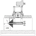
图2是本发明切石机及其上的刀轮的构造示意图;Fig. 2 is the structural representation of the stone cutter of the present invention and the cutter wheel on it;
图3是本发明刀轮的构造示意图(省略转动主轴);Fig. 3 is the structural schematic diagram of the cutter wheel of the present invention (omitting the rotating spindle);
图4是图3的右视图;Fig. 4 is the right side view of Fig. 3;
图5是锁杆的立体图;Figure 5 is a perspective view of a lock lever;
图6是锁杆的主视图;Figure 6 is a front view of the lock lever;
图7是图6的A-A剖面图;Fig. 7 is the A-A sectional view of Fig. 6;
图8是一种规格锯片的主视图;Figure 8 is a front view of a specification saw blade;
图9是图8的K部放大图;Fig. 9 is the K part enlarged view of Fig. 8;
图10是内、外轴组合刀轮结构的主视剖面图;Figure 10 is a front sectional view of the inner and outer shaft combined cutter wheel structure;
图11、12是图10的局部视图;Figures 11 and 12 are partial views of Figure 10;
图13是图3另一种实施例图。FIG. 13 is a diagram of another embodiment of FIG. 3 .
具体实施方式:Detailed ways:
为让本发明的上述特征和优点能更明显易懂,下文特举实施例,并配合附图,作详细说明如下。In order to make the above-mentioned features and advantages of the present invention more obvious and easy to understand, the following specific embodiments are given and the accompanying drawings are described in detail as follows.
本发明塔式多组片组合刀轮包括转动主轴1和套设在转动主轴1上的若干组直径依次增大的锯片(各组依次增大的直径数值最好相同),每组锯片具有多片相互平行设置且直径相同的锯片2,每组锯片具有2-10片锯片,转动主轴上具有2-12组锯片,本申请以每组4片锯片,共7组为图例(如图3所示),其中最小直径锯片直径1050mm,相邻组锯片的直径相差100 mm,最大直径那组锯片的直径1650 mm,其它直径的锯片等均可,上述结构的优点通过下面工作对比说明:The tower-type multi-group blade combination cutter wheel of the present invention includes a rotating spindle 1 and several groups of saw blades with successively increased diameters sleeved on the rotating spindle 1 (the diameter values of the successively increased groups are preferably the same). Each group of saw blades There are a plurality of
现有尖塔形刀轮每次沿转动主轴轴向(图1的X向)的进刀均是相邻锯片的中心间距(通常该值为5-15mm),轴向进刀后刀轮移动至石材最后端,以一定固定值沿竖向下刀(图1的Z向),然后沿垂直图1图面方向向外移动切割石材,当刀轮移动至石材最前端后再以一定固定值(通常为相邻锯片半径的差值)沿竖向下刀(图1的Z向),继续沿垂直图1图面方向向里移动切割石材,接着刀轮再沿转动主轴轴向(图1的X向)进刀,进刀值即为相邻锯片的中心间距,接着如前所述循环,因此使用现有尖塔形刀轮加工时,沿转动主轴轴向进刀次数即为锯片的数量,显然该步骤和方法加工的效率较低。Every time the existing spire-shaped cutter wheel feeds along the axis of the rotating spindle (X direction in Figure 1), it is the center distance between adjacent saw blades (usually the value is 5-15mm), and the cutter wheel moves after the axial feed. To the end of the stone, cut the stone vertically with a certain fixed value (Z direction in Figure 1), and then move outward in the direction perpendicular to the surface of Figure 1 to cut the stone. When the cutter wheel moves to the front end of the stone, use a certain fixed value (usually the difference between the radii of adjacent saw blades) down the knife vertically (Z direction in Figure 1), continue to move inward to cut the stone in the direction perpendicular to the surface of Figure 1, and then move the cutter wheel along the axis of the rotating spindle (Figure 1). 1 X direction) feed, the feed value is the center distance between adjacent saw blades, and then cycle as described above, so when using the existing spire-shaped cutter wheel for machining, the number of feeds along the axis of the rotating spindle is the saw blade. The number of sheets, obviously the processing efficiency of this step and method is low.
本申请结构的加工步骤是,首先刀轮沿转动主轴轴向(图2的X向)的进刀即是一组锯片的厚度(每组锯片具有多片,该进刀值为10-100 mm);轴向进刀后刀轮移动至石材最后端,以一定固定值(通常为相邻组锯片半径的差值)沿竖向下刀(图2的Z向),然后沿垂直图2图面方向向外移动切割石材,当刀轮移动至石材最前端后再以一定固定值(通常为相邻组锯片半径的差值)沿竖向下刀(图2的Z向),继续沿垂直图2图面方向向里移动切割石材,接着刀轮再沿转动主轴轴向(图2的X向)进刀,进刀值即为一组锯片的厚度,接着如前所述循环,因此使用本申请刀轮加工时,沿转动主轴轴向进刀次数显然较现有夹塔刀轮少,加工效率显著提高。The processing steps of the structure of the present application are as follows: first, the feed of the cutter wheel along the axis of the rotating spindle (X direction in FIG. 2 ) is the thickness of a group of saw blades (each group of saw blades has multiple pieces, and the feed value is 10- 100 mm); after the axial feed, the cutter wheel moves to the last end of the stone, and cuts down vertically (Z direction in Figure 2) at a fixed value (usually the difference between the radii of adjacent groups of saw blades), and then vertically Move the cutting stone outward in the direction of the picture in Figure 2. When the cutter wheel moves to the front end of the stone, it will cut down vertically with a certain fixed value (usually the difference between the radii of the adjacent saw blades) (Z direction in Figure 2) , continue to move inward to cut the stone in the direction perpendicular to the surface of Figure 2, and then the cutter wheel feeds along the axis of the rotating spindle (X direction in Figure 2), the feed value is the thickness of a group of saw blades, and then as before Therefore, when the tool wheel of the present application is used for processing, the number of tool feeds along the axis of the rotating spindle is obviously less than that of the existing turret tool wheel, and the processing efficiency is significantly improved.
另外,目前尖塔状刀轮中的锯片直径从大到小,直径相差悬殊,使的主轴的转速不能就大直径锯片或小直径锯片,当就小直径锯片时会使大直径锯片的线速度过大,大直径锯片容易损坏,而就大直径的锯片,小直径锯片磨损较严重,需要经常更换小直径锯片的刀头,因此通常只能就中间直径锯片的速度,也就使得锯片切割速度无法进一步提高,另外,由于小直径锯片的直径仅仅比主轴的直径略大,在整个下刀切割过程,需要频繁停机,每停机依次将一个较小直径的锯片卸下,从而也大大影响切割效率。In addition, the diameter of the saw blade in the current spire-shaped cutter wheel varies from large to small, and the diameters are very different, so that the rotation speed of the main shaft cannot be used for the large-diameter saw blade or the small-diameter saw blade. If the linear speed of the blade is too large, the large-diameter saw blade is easily damaged, while for the large-diameter saw blade, the small-diameter saw blade wears more seriously, and the cutter head of the small-diameter saw blade needs to be replaced frequently. In addition, since the diameter of the small-diameter saw blade is only slightly larger than the diameter of the main shaft, frequent shutdowns are required during the entire lower-knife cutting process. The saw blade is removed, which also greatly affects the cutting efficiency.
本申请由于最大、最小锯片直径相差较小,所以基本上能保证大小锯片磨损一致,从而减少中途频繁更换小锯片;也由于最小锯片直径较大,由此提高了排削速度和效率切割。Since the difference between the maximum and minimum saw blade diameters is small, the application can basically ensure uniform wear of the large and small saw blades, thereby reducing frequent replacement of small saw blades in the middle; also because the diameter of the minimum saw blade is large, thereby improving the cutting speed and efficiency. Efficient cutting.
上述的转动主轴转动连接在主轴箱内,各锯片可以设在转动主轴的一端,而另一端通过皮带轮机构驱动该转动主轴转动。The above-mentioned rotating spindle is rotatably connected in the spindle box, each saw blade can be arranged on one end of the rotating spindle, and the other end drives the rotating spindle to rotate through a pulley mechanism.
上述相邻两锯片之间的间距是相等的,从而才能确保多次切割进给和加工等厚度的石材片。The spacing between the above two adjacent saw blades is equal, so as to ensure multiple cutting, feeding and processing of stone pieces of equal thickness.
进一步的,为了实现各锯片与转动主轴的同步转动,上述锯片上具有套在转动主轴上的通孔3,在通孔上均设有至少一个的键槽4,具体可以是2-5个,本申请图例为在通孔中具有3个键槽4,转动主轴上设有相应的凸键。Further, in order to realize the synchronous rotation of each saw blade and the rotating main shaft, the above-mentioned saw blade has a through
本申请上述锯片的厚度为1.2-3.0mm,锯片的直径为800-3000mm。The thickness of the above-mentioned saw blade in the present application is 1.2-3.0 mm, and the diameter of the saw blade is 800-3000 mm.
本申请锁杆连接结构的锯片上布设有若干个非全圆形定位孔5(在锯片上可以设置6-27个),在各锯片2的非全圆形定位孔5中穿设有用于锁定各锯片2的锁杆6,该非全圆形定位孔5可以是椭圆形孔、条形孔等等形状。Several non-full circular positioning holes 5 (6-27 can be set on the saw blade) are arranged on the saw blade of the locking lever connection structure of the present application, and the non-full
锁杆6的截面与非全圆形定位孔的形状相当,即锁杆6可穿过非全圆形定位孔5,该锁杆6也即可以是椭圆形或条形等等,在锁杆上间隔设有限位锯片的切缝7,该切缝与锯片可以是过渡配合或小间隙配合,切缝中的轴段8限位在非全圆形定位孔中转动,切缝中的轴段8截面可以是圆形等,以使其可以在非全圆形定位孔中转动,当然其它的形状,如矩形或椭圆形等均可,但为了方便加工,轴段8的截面为圆形。The cross section of the locking
上述锁杆6包括中间锁紧段杆体9和位于中间锁紧段杆体两端的缩径轴段杆体10,所述中间锁紧段杆体9为圆轴两侧削平形成两个平台11,两个平台相互平行,所述切缝7为等间距的设在中间锁紧段杆体上,相邻切缝的间距即为刀轮上相邻锯片的间距,切缝中的轴段的截面形状为圆形等。The above-mentioned
进一步的,上述非全圆形定位孔5截面为圆形缺少两个劣弧,在缺少的两个劣弧处连接有弦12,两个弦相互平行,两个弦的间距大于或等于切缝中圆轴段的直径。Further, the above-mentioned non-full-
进一步的,上述缩径轴段杆体上锁紧有螺母或限位片。Further, a nut or a limiting piece is locked on the rod body of the diameter-reducing shaft section.
在加工该锁杆6时,可以根据尺寸先车削出均为光轴的中间锁紧段杆体9和缩径轴段杆体10,同时在同一定位工位车出多个切缝7(也可同时在缩径轴段杆体10上车出螺纹),同一定位工位中加工出所有用于定位锯片的切缝7,不仅加工效率高、成本低,而且也有利于保证加工精度;然后在铣床上铣平两个平台11,基本完成了锁杆6的加工,本申请锁杆6的结构简单、设计巧妙,与各锯片的拆装非常方便,仅仅需要锁杆6穿过非全圆形定位孔5后旋转90度并锁上螺母即可,从而大大方便了在锯切石材时各锯片的组装和拆卸锁杆,提高了锯切石材的效率。When machining the
本申请锁杆连接结构可以应用在多片等直径锯片的刀轮上使用(如图13所示),也可以应用在本申请的塔式多组片组合刀轮中(如图2-4所示),也可以应用在传统的尖塔状的刀轮中。The locking bar connection structure of the present application can be applied to the cutter wheel of multiple equal-diameter saw blades (as shown in Figure 13), and can also be applied to the tower-type multi-group blade combination cutter wheel of the present application (as shown in Figure 2-4). shown), can also be used in conventional spire-shaped cutter wheels.
本发明塔式多组片组合刀轮的切石机,包括机体A1和设在机体上的主轴箱A2,所述主轴箱A2上设有塔式多组片组合刀轮A3。The tower-type multi-slice combined cutter wheel stone cutter of the present invention includes a body A1 and a main shaft box A2 arranged on the main body.
本发明塔式多组片组合刀轮的工作方法,所述塔式多组片组合刀轮包括转动主轴1和套设在转动主轴1上的若干组直径依次增大的锯片,每组锯片具有多片相互平行设置且直径相同的锯片2,每组锯片具有2-10片锯片,转动主轴上具有2-12组锯片,本申请以每组4片锯片,共7组为图例,其中最小直径锯片直径1050mm,相邻组锯片的直径相差100 mm;安装时,将多片直径相同的锯片组成一组锯片,各锯片之间具有隔片13,各组锯片直径依次增大,每组锯片中各锯片直径相等,并将各组锯片从转动主轴一侧依次套入,进而形成塔式多组片组合刀轮。The working method of the tower-type multi-group blade combination cutter wheel of the present invention, the tower-type multi-group blade combination cutter wheel comprises a rotating main shaft 1 and several groups of saw blades whose diameters increase sequentially, which are sleeved on the rotating main shaft 1. Each group of saw blades The blade has a plurality of
进一步的,为了方便安装,上述锯片上布设有若干个非全圆形定位孔5,在各锯片2的非全圆形定位孔5中穿设有用于锁定各锯片2的锁杆6,该非全圆形定位孔5可以是椭圆形孔、条形孔等等形状;安装时,将套在转动主轴上各锯片的非全圆形定位孔调整至同轴位置(每个锯片通常有一至三圈的非全圆形定位孔,每圈具有多个非全圆形定位孔,非全圆形定位孔调整至同轴位置即使各非全圆形定位孔位置要基本一致),在非全圆形定位孔5中穿入锁杆6,锁杆穿入后需要各锯片正对切缝7位置,在锁杆完全穿过后旋转一定角度(通常90度),使锁杆无法再拔出,在锁杆两端中间锁紧段杆体9上用螺母锁紧固定。Further, in order to facilitate installation, several non-full
本发明塔式多组片组合刀轮的优点:The advantages of the tower-type multi-group blade combination cutter wheel of the present invention:
1、由于最大、最小锯片直径相差较小,所以基本上能保证大小锯片磨损一致,从而减少中途频繁更换小锯片。1. Because the difference between the largest and smallest saw blade diameters is small, it can basically ensure that the large and small saw blades wear uniformly, thereby reducing frequent replacement of small saw blades in the middle.
2、由于最小锯片直径较大,由此提高了排削速度和效率切割。2. Due to the larger diameter of the minimum saw blade, the cutting speed and cutting efficiency are improved.
3、塔式多组合锁扣刀轮安装了塔式锯片锁扣旋转杆(锁杆)能够起到锯片整体稳定性,同时可以做到两组及两组以上同直径的阶梯型组合锯片安装方式。3. The tower-type multi-combination locking cutter wheel is equipped with a tower-type saw blade lock rotating rod (lock rod), which can achieve the overall stability of the saw blade, and can achieve two or more sets of ladder-type combination saws with the same diameter. chip installation.
4、塔式多组合锁扣刀轮可以安装最薄锯片厚度至2.5mm,达到节省材料,节约能耗和减少废粉排放。4. The tower-type multi-combination locking cutter wheel can be installed with the thinnest saw blade thickness to 2.5mm, which can save materials, save energy and reduce waste powder discharge.
另外本申请刀轮可以使用内、外轴组合刀轮结构,以实现一些组锯片的转动速度不同,以减小共振振动。In addition, the cutter wheel of the present application can use the inner and outer shaft combined cutter wheel structure, so as to realize that the rotation speeds of some groups of saw blades are different, so as to reduce the resonance vibration.
本发明内、外轴组合刀轮结构包括主轴箱A2、转动连接在主轴箱A2内的外转轴A4、套设在外转轴A4体内可独立转动的内转轴A5,外转轴通过轴承转动铰接在主轴箱A2内部,外转轴A4为空心管筒状,内转轴可以是实心轴,所述内转轴A5的第一端A501和第二端A502分别均长出外转轴A4的第一端A401和第二端A402,所述外转轴A4的第一端与内转轴A5的第一端上均固定连接有多片平行间隔并排设置的锯片,锯片的厚度通常相同,锯片的间距通常也相同,位于外转轴上的第一锯片A6直径与位于内转轴上的第二锯片A7直径不同(第一锯片可以是前述较大直径的几组锯片,第二锯片可以是前述较小直径的几组锯片);所述外转轴的第二端与内转轴的第二端上均固定连接有带轮,位于外转轴上的第一带轮A8直径与位于内转轴上的第二带轮A9直径不同,以使第一锯片A6与第二锯片A7具有不同的转速(不同转速的锯片可以分别连接锁杆,或者较小直径的锯片可以不安装锁杆,锯片与锯片之间设有隔离片),通过第一锯片A6与第二锯片A7具有不同的转速,可以使第一、第二锯片可产生不同的振动频率,两种不同的振动频率相互消减,避免了所有锯片产生相同的频率而产生较大的共振。The combined tool wheel structure of the inner and outer shafts of the present invention includes a spindle box A2, an outer rotating shaft A4 rotatably connected in the spindle box A2, and an inner rotating shaft A5 sleeved inside the outer rotating shaft A4 and rotatable independently. The outer rotating shaft is hinged to the spindle box through bearings. Inside A2, the outer shaft A4 is in the shape of a hollow tube, the inner shaft can be a solid shaft, and the first end A501 and the second end A502 of the inner shaft A5 both grow out of the first end A401 and the second end A402 of the outer shaft A4, respectively , the first end of the outer rotating shaft A4 and the first end of the inner rotating shaft A5 are fixedly connected with a plurality of saw blades arranged side by side at parallel intervals. The thickness of the saw blades is usually the same, and the spacing of the saw blades is usually the same. The diameter of the first saw blade A6 on the rotating shaft is different from the diameter of the second saw blade A7 located on the inner rotating shaft (the first saw blade can be several sets of saw blades of the aforementioned larger diameter, and the second saw blade can be the aforementioned smaller diameter. Several sets of saw blades); the second end of the outer shaft and the second end of the inner shaft are fixedly connected with pulleys, the diameter of the first pulley A8 on the outer shaft and the second pulley on the inner shaft are The diameters of A9 are different, so that the first saw blade A6 and the second saw blade A7 have different rotation speeds (saw blades with different rotation speeds can be connected to the lock lever respectively, or the smaller diameter saw blade can be installed without the lock lever, the saw blade and the saw There is a spacer between the blades), the first saw blade A6 and the second saw blade A7 have different rotational speeds, so that the first and second saw blades can generate different vibration frequencies, and the two different vibration frequencies are mutually reduced. , to avoid large resonance caused by the same frequency of all saw blades.
内、外轴组合刀轮结构的工作原理:通过动力输入设备(电机及皮带轮机构)提供给外转轴和内转轴不同的转动速度,从而有利于使分别设在内转轴和外转轴上的锯片可产生不同的振动频率,两种不同的振动频率相互消减,避免了所有锯片产生相同的频率而产生较大的共振。The working principle of the combined cutter wheel structure of the inner and outer shafts: different rotational speeds are provided to the outer shaft and the inner shaft through the power input device (motor and pulley mechanism), which is conducive to making the saw blades set on the inner shaft and the outer shaft respectively. Different vibration frequencies can be generated, and the two different vibration frequencies are mutually attenuated, avoiding the large resonance caused by the same frequency of all saw blades.
本发明的内、外轴组合刀轮可避免产生共振现象,有利于提高石材切割表面的平整度、提高石材的切割效率,后续无需另外研磨加工,降低耗能;同时可减少锯片上刀头的损坏,提高锯片的使用寿命,降低成本。The inner and outer shaft combined cutter wheel of the present invention can avoid the resonance phenomenon, which is beneficial to improve the flatness of the stone cutting surface and the cutting efficiency of the stone, without the need for additional grinding processing in the follow-up, reducing energy consumption; at the same time, it can reduce the cutter head on the saw blade damage, improve the service life of the saw blade and reduce the cost.
最后应当说明的是:以上实施例仅用以说明本发明的技术方案而非对其限制;尽管参照较佳实施例对本发明进行了详细的说明,所属领域的普通技术人员应当理解,依然可以对本发明的具体实施方式进行修改或者对部分技术特征进行等同替换;而不脱离本发明技术方案的精神,其均应涵盖在本发明请求保护的技术方案范围当中。Finally, it should be noted that the above embodiments are only used to illustrate the technical solutions of the present invention and not to limit them; although the present invention has been described in detail with reference to the preferred embodiments, those of ordinary skill in the art should The specific embodiments of the invention are modified or some technical features are equivalently replaced; without departing from the spirit of the technical solutions of the present invention, all of them should be included in the scope of the technical solutions claimed in the present invention.
Claims (10)
Priority Applications (1)
| Application Number | Priority Date | Filing Date | Title |
|---|---|---|---|
| CN202010924684.XA CN111873192A (en) | 2020-09-05 | 2020-09-05 | Tower type multi-group-blade combined cutter wheel, stone cutting machine and working method |
Applications Claiming Priority (1)
| Application Number | Priority Date | Filing Date | Title |
|---|---|---|---|
| CN202010924684.XA CN111873192A (en) | 2020-09-05 | 2020-09-05 | Tower type multi-group-blade combined cutter wheel, stone cutting machine and working method |
Publications (1)
| Publication Number | Publication Date |
|---|---|
| CN111873192A true CN111873192A (en) | 2020-11-03 |
Family
ID=73199103
Family Applications (1)
| Application Number | Title | Priority Date | Filing Date |
|---|---|---|---|
| CN202010924684.XA Pending CN111873192A (en) | 2020-09-05 | 2020-09-05 | Tower type multi-group-blade combined cutter wheel, stone cutting machine and working method |
Country Status (1)
| Country | Link |
|---|---|
| CN (1) | CN111873192A (en) |
Cited By (3)
| Publication number | Priority date | Publication date | Assignee | Title |
|---|---|---|---|---|
| CN114654598A (en) * | 2022-05-26 | 2022-06-24 | 福建省南安市巨轮机械有限公司 | Cutting machine with large and small saw blade groups separated and cutting method thereof |
| FR3129620A1 (en) * | 2021-12-01 | 2023-06-02 | Illinois Tool Works | cutting tool |
| CN116291443A (en) * | 2023-02-01 | 2023-06-23 | 五莲县山前石材有限公司 | Method and system for combined sawing and mining of stone slabs |
Citations (6)
| Publication number | Priority date | Publication date | Assignee | Title |
|---|---|---|---|---|
| JPH0699426A (en) * | 1991-10-14 | 1994-04-12 | C Bataria Gino | Machine for reducing thickness of stone slab and method therefor |
| CN202225310U (en) * | 2011-10-17 | 2012-05-23 | 福建万龙金刚石工具有限公司 | Stable and efficient bridge type stone cutting machine |
| CN203919407U (en) * | 2014-05-22 | 2014-11-05 | 苏友谊 | The ultra-thin combination cutting wheel structure of bayonet type |
| CN206953313U (en) * | 2017-07-26 | 2018-02-02 | 黄春生 | New double rotating shaft main spindle boxes |
| CN212471983U (en) * | 2020-09-05 | 2021-02-05 | 苏子泷 | Stone cutters using tower-type multi-slice combination cutter wheels |
| CN212666409U (en) * | 2020-09-05 | 2021-03-09 | 苏子泷 | Tower type multi-piece combination cutter wheel |
-
2020
- 2020-09-05 CN CN202010924684.XA patent/CN111873192A/en active Pending
Patent Citations (6)
| Publication number | Priority date | Publication date | Assignee | Title |
|---|---|---|---|---|
| JPH0699426A (en) * | 1991-10-14 | 1994-04-12 | C Bataria Gino | Machine for reducing thickness of stone slab and method therefor |
| CN202225310U (en) * | 2011-10-17 | 2012-05-23 | 福建万龙金刚石工具有限公司 | Stable and efficient bridge type stone cutting machine |
| CN203919407U (en) * | 2014-05-22 | 2014-11-05 | 苏友谊 | The ultra-thin combination cutting wheel structure of bayonet type |
| CN206953313U (en) * | 2017-07-26 | 2018-02-02 | 黄春生 | New double rotating shaft main spindle boxes |
| CN212471983U (en) * | 2020-09-05 | 2021-02-05 | 苏子泷 | Stone cutters using tower-type multi-slice combination cutter wheels |
| CN212666409U (en) * | 2020-09-05 | 2021-03-09 | 苏子泷 | Tower type multi-piece combination cutter wheel |
Cited By (4)
| Publication number | Priority date | Publication date | Assignee | Title |
|---|---|---|---|---|
| FR3129620A1 (en) * | 2021-12-01 | 2023-06-02 | Illinois Tool Works | cutting tool |
| EP4190522A1 (en) * | 2021-12-01 | 2023-06-07 | Illinois Tool Works Inc. | Wall groove milling cutter |
| CN114654598A (en) * | 2022-05-26 | 2022-06-24 | 福建省南安市巨轮机械有限公司 | Cutting machine with large and small saw blade groups separated and cutting method thereof |
| CN116291443A (en) * | 2023-02-01 | 2023-06-23 | 五莲县山前石材有限公司 | Method and system for combined sawing and mining of stone slabs |
Similar Documents
| Publication | Publication Date | Title |
|---|---|---|
| CN111873192A (en) | Tower type multi-group-blade combined cutter wheel, stone cutting machine and working method | |
| CN103658698A (en) | Cylinder rapid forming tool | |
| CN106891047A (en) | One kind bending axial workpiece external cutting processing unit (plant) and cutting working method | |
| CN202387972U (en) | Balancing axle hole boring cutter | |
| CN210589777U (en) | Circular bamboo ring array saw blade group | |
| CN212471983U (en) | Stone cutters using tower-type multi-slice combination cutter wheels | |
| CN101745705A (en) | New high-efficiency whirling milling head | |
| CN115816586B (en) | Bamboo segment breaking and inner joint removing mechanism | |
| CN212666409U (en) | Tower type multi-piece combination cutter wheel | |
| CN201239817Y (en) | Novel efficient cyclone milling head | |
| CN109249495B (en) | Bamboo section inner joint strickle device | |
| CN210139486U (en) | Bamboo section inner segment strickles device off | |
| CN213796843U (en) | A blade slitting device | |
| CN219027833U (en) | Bamboo chip pressing and conveying mechanism | |
| CN213353001U (en) | Lock rod connecting structure of combined knife flywheel | |
| CN101502967B (en) | Splitting machine | |
| CN212666408U (en) | Two-speed combination cutter wheel, stone cutter | |
| CN111390257A (en) | A quick-change rail milling cutter | |
| CN112846883B (en) | Main shaft movable machine tool with quick tool changing function | |
| CN103658837A (en) | Spiral blade scrap chopper | |
| CN219618176U (en) | Cutting saw blade spindle convenient to disassemble and assemble and slitting grooving machine | |
| CN104923857B (en) | A kind of application method of square hole drilling rig | |
| CN111283818B (en) | A movable device for a multi-saw blade band saw machine | |
| CN212286020U (en) | A quick-change rail milling cutter | |
| CN211729532U (en) | Bamboo breaking machine |
Legal Events
| Date | Code | Title | Description |
|---|---|---|---|
| PB01 | Publication | ||
| PB01 | Publication | ||
| SE01 | Entry into force of request for substantive examination | ||
| SE01 | Entry into force of request for substantive examination |