CN111830889B - Power supply control device and power supply - Google Patents
Power supply control device and power supply Download PDFInfo
- Publication number
- CN111830889B CN111830889B CN201910302852.9A CN201910302852A CN111830889B CN 111830889 B CN111830889 B CN 111830889B CN 201910302852 A CN201910302852 A CN 201910302852A CN 111830889 B CN111830889 B CN 111830889B
- Authority
- CN
- China
- Prior art keywords
- started
- signal
- interface
- power supply
- pin
- Prior art date
- Legal status (The legal status is an assumption and is not a legal conclusion. Google has not performed a legal analysis and makes no representation as to the accuracy of the status listed.)
- Active
Links
- 238000004891 communication Methods 0.000 claims description 55
- 238000000034 method Methods 0.000 claims description 11
- 230000008569 process Effects 0.000 claims description 7
- 238000012545 processing Methods 0.000 claims description 5
- 238000012790 confirmation Methods 0.000 claims description 3
- 230000002159 abnormal effect Effects 0.000 claims 2
- 230000003137 locomotive effect Effects 0.000 description 21
- 238000010586 diagram Methods 0.000 description 8
- 230000004044 response Effects 0.000 description 4
- 230000005856 abnormality Effects 0.000 description 2
- 238000012986 modification Methods 0.000 description 2
- 230000004048 modification Effects 0.000 description 2
- 238000006243 chemical reaction Methods 0.000 description 1
- 238000013461 design Methods 0.000 description 1
- 238000001514 detection method Methods 0.000 description 1
- 238000011161 development Methods 0.000 description 1
- 238000002474 experimental method Methods 0.000 description 1
- 230000003993 interaction Effects 0.000 description 1
- 238000006467 substitution reaction Methods 0.000 description 1
- 238000012795 verification Methods 0.000 description 1
- 239000002699 waste material Substances 0.000 description 1
Images


Classifications
-
- G—PHYSICS
- G05—CONTROLLING; REGULATING
- G05B—CONTROL OR REGULATING SYSTEMS IN GENERAL; FUNCTIONAL ELEMENTS OF SUCH SYSTEMS; MONITORING OR TESTING ARRANGEMENTS FOR SUCH SYSTEMS OR ELEMENTS
- G05B19/00—Programme-control systems
- G05B19/02—Programme-control systems electric
- G05B19/04—Programme control other than numerical control, i.e. in sequence controllers or logic controllers
- G05B19/048—Monitoring; Safety
-
- G—PHYSICS
- G05—CONTROLLING; REGULATING
- G05B—CONTROL OR REGULATING SYSTEMS IN GENERAL; FUNCTIONAL ELEMENTS OF SUCH SYSTEMS; MONITORING OR TESTING ARRANGEMENTS FOR SUCH SYSTEMS OR ELEMENTS
- G05B2219/00—Program-control systems
- G05B2219/20—Pc systems
- G05B2219/26—Pc applications
- G05B2219/2603—Steering car
-
- G—PHYSICS
- G05—CONTROLLING; REGULATING
- G05B—CONTROL OR REGULATING SYSTEMS IN GENERAL; FUNCTIONAL ELEMENTS OF SUCH SYSTEMS; MONITORING OR TESTING ARRANGEMENTS FOR SUCH SYSTEMS OR ELEMENTS
- G05B2219/00—Program-control systems
- G05B2219/20—Pc systems
- G05B2219/26—Pc applications
- G05B2219/2637—Vehicle, car, auto, wheelchair
-
- Y—GENERAL TAGGING OF NEW TECHNOLOGICAL DEVELOPMENTS; GENERAL TAGGING OF CROSS-SECTIONAL TECHNOLOGIES SPANNING OVER SEVERAL SECTIONS OF THE IPC; TECHNICAL SUBJECTS COVERED BY FORMER USPC CROSS-REFERENCE ART COLLECTIONS [XRACs] AND DIGESTS
- Y02—TECHNOLOGIES OR APPLICATIONS FOR MITIGATION OR ADAPTATION AGAINST CLIMATE CHANGE
- Y02T—CLIMATE CHANGE MITIGATION TECHNOLOGIES RELATED TO TRANSPORTATION
- Y02T90/00—Enabling technologies or technologies with a potential or indirect contribution to GHG emissions mitigation
- Y02T90/10—Technologies relating to charging of electric vehicles
- Y02T90/16—Information or communication technologies improving the operation of electric vehicles
Landscapes
- Physics & Mathematics (AREA)
- General Physics & Mathematics (AREA)
- Engineering & Computer Science (AREA)
- Automation & Control Theory (AREA)
- Electric Propulsion And Braking For Vehicles (AREA)
- Power Sources (AREA)
Abstract
The embodiment of the invention provides a power supply control device and a power supply, wherein the power supply control device comprises: the device comprises a first interface, a second interface, a timing unit, a restart signal sending unit and a first switch unit. In the power supply control device provided by the embodiment of the invention, after the power supply accessed by the first interface is powered on, the timing unit performs timing, and if the timing duration exceeds the preset duration, and the second interface does not receive the first starting signal of the first device to be started, the situation that the first device to be started is not powered on can be described.
Description
Technical Field
The invention relates to the field of circuits, in particular to a power supply control device and a power supply.
Background
With the development of society, locomotives controlled by a microcomputer network are more developed, and the microcomputer network control can be as follows: the control system adopts a standardized and modularized circuit design.
In the prior art, a Central Processing Unit (MPU) is usually used as a main control part for controlling a microcomputer network of a locomotive to control the operation of the locomotive.
However, with the increase of the usage time limit of the locomotive in the prior art, the phenomenon that the MPU is powered on and not started often occurs, and the powering on and not starting of the MPU may specifically be: after the locomotive is integrally electrified, the MPU which is supposed to be started simultaneously when the locomotive is electrified is not actually started, so that the MPU cannot normally work, a driver needs to manually restart the MPU to ensure that the MPU normally works, and inconvenience is brought to the driving operation of the driver.
Disclosure of Invention
The invention provides a power supply control device and a power supply, which are used for simplifying the operation that an operator does not start an MPU when the MPU is electrified.
A first aspect of an embodiment of the present invention provides a power supply control apparatus, including:
the device comprises a first interface, a second interface, a timing unit, a restart signal sending unit and a first switch unit;
wherein the first interface is in communication connection with the timing unit; the second interface is in communication connection with the restart signal sending unit; the timing unit is in communication connection with the restart signal sending unit; the restarting signal sending unit is electrically connected with the first switch unit;
the first interface is used for accessing a power supply;
the second interface is used for accessing a first device to be started and receiving a first signal of the first device to be started; the first signal is used for indicating that the first device to be started is in a starting state;
the timing unit is used for timing after the power supply accessed by the first interface is powered on;
the restart signal sending unit is used for sending a second signal if the second interface does not receive the first signal of the first device to be started under the condition that the timing duration of the timing unit exceeds the preset duration; the second signal is used for indicating the first switching unit to restart the first device to be started;
the first switch unit is used for accessing the first device to be started and carrying out the restarting operation of the first device to be started under the condition of receiving the second signal.
Optionally, the method further includes:
a third interface and a second switching unit; the third interface is in communication connection with the restart signal sending unit; the restart signal sending unit is also electrically connected with the second switch unit;
the third interface is used for accessing a second device to be started and receiving a third signal of the second device to be started; the third signal is used for indicating that the second device to be started is in a starting state;
the restart signal sending unit is further configured to send a fourth signal if the second start information of the second device to be started is not received at the third interface under the condition that the timing duration of the timing unit exceeds a preset duration; the fourth signal is used for indicating the second switch unit to restart the second device to be started;
the second switch unit is configured to access the second device to be started, and execute a restart operation on the second device to be started when the fourth signal is received.
Optionally, the method further includes:
the fifth signal generating unit is used for generating a fifth signal, and the fifth signal is used for indicating that the power supply control device operates normally;
the second interface is further configured to send the fifth signal to the first device to be started;
the third interface is further configured to send the fifth signal to the second device to be started.
Optionally, the second interface includes: thirty-two pins; wherein, among the thirty-two pins, the first pin,
the first to fourth pins are configured as pins that transmit the fifth signal;
the fifth pin to the eighth pin are configured as pins for transmitting a sixth signal, and the sixth signal is used for indicating that the first device to be started operates normally;
the ninth pin to the twelfth pin are configured as pins for transmitting a seventh signal, and the seventh signal is used for indicating that the second device to be started operates normally;
the thirteenth pin is a pin configured to transmit an eighth signal, where the eighth signal is used to indicate a power-off fault of the first device to be started;
the fourteenth pin is configured as a pin for transmitting a ninth signal, and the ninth signal is used for indicating that the first device to be started is not started after being powered on;
the fifteenth pin is a pin configured to transmit a tenth signal, where the tenth signal is used to indicate a power-off failure of the second device to be activated;
the sixteenth pin is a pin configured to transmit an eleventh signal, where the eleventh signal is used to indicate that the second device to be started is not started after being powered on;
the seventeenth pin is a pin configured to transmit a twelfth signal, wherein the twelfth signal is used for indicating that the first device to be started and the second device to be started both have power-off faults;
the eighteenth pin is configured as a pin for transmitting a thirteenth signal, wherein the thirteenth signal is used for indicating that the first device to be started and the second device to be started are both powered on and not started;
the nineteenth pin is configured as a pin of the port check 0 bit;
the twentieth pin is configured as a port check 1-bit pin;
the twenty-first pin to the thirty-second pin are vacant pins.
Optionally, the second interface is an interface based on a multifunctional vehicle bus MVB communication mode.
Optionally, the third interface is an interface based on a multifunctional vehicle bus MVB communication mode communication.
Optionally, the first switch unit includes: a first relay.
Optionally, the second switch unit includes: and a second relay.
Optionally, the first device to be started is a first central control unit, and the first central control unit is used as a main control device to control the vehicle to operate; the second device to be started is a second central control unit, and the second central control unit is used as a redundant device to assist in controlling the vehicle to run.
A second aspect of the embodiments of the present invention provides a power supply including any one of the power supply control apparatuses.
The power supply control device and the power supply provided by the embodiment of the invention comprise: the device comprises a first interface, a second interface, a timing unit, a restart signal sending unit and a first switch unit; the first interface is in communication connection with the timing unit; the second interface is in communication connection with the restart signal sending unit; the timing unit is in communication connection with the restart signal sending unit; the restart signal sending unit is electrically connected with the first interface of the first switch unit and is used for accessing a power supply; the second interface is used for accessing the first device to be started and receiving a first signal of the first device to be started, wherein the first signal is used for indicating that the first device to be started is in a starting state; the timing unit is used for timing after the power supply accessed by the first interface is electrified; the restarting signal sending unit is used for sending a second signal if the second interface does not receive the first signal of the first device to be started under the condition that the timing duration of the timing unit exceeds the preset duration, and the second signal is used for indicating the first switch unit to restart the first device to be started; and the first switching unit is used for accessing the first device to be started and executing the restarting operation of the first device to be started under the condition of receiving the second signal. When the power control device controls the locomotive to work based on the embodiment of the invention, the timing unit performs timing after the power supply accessed by the first interface is powered on, if the timing duration exceeds the preset duration, and the second interface does not receive the first starting signal of the first device to be started, the situation that the first device to be started is not powered on can be described, therefore, the first restarting signal can be sent to the first switch unit through the restarting signal sending unit, the first switch unit further executes the restarting operation of the first device to be started, the whole restarting process is automatically performed, and no operation is required to be performed by an operator, so that the operation of the operator on the phenomenon that the first device to be started is not powered on can be simplified.
Drawings
FIG. 1 is a schematic diagram of a power control apparatus according to an embodiment of the present invention;
FIG. 2 is a schematic structural diagram of a power control apparatus according to an embodiment of the invention;
FIG. 3 is a schematic diagram of an interface structure according to an embodiment of the present invention;
fig. 4 is a schematic structural diagram of a power control apparatus according to an embodiment of the invention.
Detailed Description
The technical solutions in the embodiments of the present invention will be clearly and completely described below with reference to the drawings in the embodiments of the present invention, and it is obvious that the described embodiments are only a part of the embodiments of the present invention, and not all of the embodiments. All other embodiments, which can be derived by a person skilled in the art from the embodiments given herein without making any creative effort, shall fall within the protection scope of the present invention.
Reference will now be made in detail to the exemplary embodiments, examples of which are illustrated in the accompanying drawings. When the following description refers to the accompanying drawings, like numbers in different drawings represent the same or similar elements unless otherwise indicated. The embodiments described in the following exemplary embodiments do not represent all embodiments consistent with the present invention. Rather, they are merely examples of apparatus and methods consistent with certain aspects of the invention, as detailed in the appended claims.
It should be understood that the described embodiments are only some embodiments of the invention, and not all embodiments. All other embodiments, which can be derived by a person skilled in the art from the embodiments given herein without making any creative effort, shall fall within the protection scope of the present invention.
The terminology used in the embodiments of the invention is for the purpose of describing particular embodiments only and is not intended to be limiting of the invention. As used in the description of the invention and the appended claims, the singular forms "a", "an", and "the" are intended to include the plural forms as well, unless the context clearly indicates otherwise.
It should be understood that the term "and/or" as used herein is merely one type of association that describes an associated object, meaning that three relationships may exist, e.g., a and/or B may mean: a exists alone, A and B exist simultaneously, and B exists alone. In addition, the character "/" herein generally indicates that the former and latter associated objects are in an "or" relationship.
It should be understood that although the terms first, second, third, etc. may be used to describe XXX in embodiments of the present invention, these XXX should not be limited to these terms. These terms are only used to distinguish XXX from each other. For example, a first XXX may also be referred to as a second XXX, and similarly, a second XXX may also be referred to as a first XXX, without departing from the scope of embodiments of the present invention.
The words "if", as used herein, may be interpreted as "at … …" or "at … …" or "in response to a determination" or "in response to a detection", depending on the context. Similarly, the phrase "if determined" or "if detected (a stated condition or event)" may be interpreted as "upon determining" or "in response to determining" or "upon detecting (a stated condition or event)" or "in response to detecting (a stated condition or event)", depending on the context.
It is also noted that the terms "comprises," "comprising," or any other variation thereof, are intended to cover a non-exclusive inclusion, such that a good or system that comprises a list of elements does not include only those elements but may include other elements not expressly listed or inherent to such good or system. Without further limitation, an element defined by the phrase "comprising an … …" does not exclude the presence of other like elements in a commodity or system that includes the element.
The power supply control device provided by the embodiment of the invention comprises: the device comprises a first interface, a second interface, a timing unit, a restart signal sending unit and a first switch unit; the first interface is in communication connection with the timing unit; the second interface is in communication connection with the restart signal sending unit; the timing unit is in communication connection with the restart signal sending unit; the restarting signal sending unit is electrically connected with the first interface of the first switch unit and is used for accessing a power supply; the second interface is used for accessing the first device to be started and receiving a first signal of the first device to be started, wherein the first signal is used for indicating that the first device to be started is in a starting state; the timing unit is used for timing after the power supply accessed by the first interface is electrified; the restarting signal sending unit is used for sending a second signal if the second interface does not receive the first signal of the first device to be started under the condition that the timing duration of the timing unit exceeds the preset duration, and the second signal is used for indicating the first switch unit to restart the first device to be started; and the first switching unit is used for accessing the first device to be started and executing the restarting operation of the first device to be started under the condition of receiving the second signal. When the power control device controls the locomotive to work based on the embodiment of the invention, the timing unit performs timing after the power supply accessed by the first interface is powered on, if the timing duration exceeds the preset duration, and the second interface does not receive the first starting signal of the first device to be started, the situation that the first device to be started is not powered on can be described, therefore, the first restarting signal can be sent to the first switch unit through the restarting signal sending unit, the first switch unit further executes the restarting operation of the first device to be started, the whole restarting process is automatically performed, and no operation is required to be performed by an operator, so that the operation of the operator on the phenomenon that the first device to be started is not powered on can be simplified.
The power supply described in the embodiment of the present invention may be a power supply that supplies an operating voltage to the MPU, and for example, the power supply may be a 110V power module commonly used in a locomotive.
The first device to be started described in the embodiment of the present invention may be an MPU, and when the MPU is powered on and is not started, the MPU may be restarted.
The first switching unit described in the embodiments of the present invention may be a relay, and the restart operation of the MPU may be implemented by the first switching unit.
The technical means of the present invention will be described in detail with reference to specific examples. The following several specific embodiments may be combined with each other, and details of the same or similar concepts or processes may not be repeated in some embodiments.
Fig. 1 is a schematic structural diagram of a power control apparatus provided in the present invention. As shown in fig. 1, the power supply control device 10 of the present invention includes:
a first interface 101, a second interface 102, a timing unit 103, a restart signal issuing unit 104, and a first switching unit 105.
Wherein, the first interface 101 is connected with the timing unit 103 in a communication way; the second interface 102 is in communication connection with the restart signal issuing unit 104; the timing unit 103 is in communication connection with the restart signal sending unit 104; the restart signal emission unit 104 is electrically connected to the first switching unit 105.
The first interface 101 is used for accessing a power supply (not shown in the figure); the second interface 102 is configured to access a first device to be started 20 and receive a first signal of the first device to be started 20; the first signal is used for indicating that the first device to be started 20 is in a starting state; the timing unit 103 is configured to perform timing after a power supply accessed by the first interface 101 is powered on; the restart signal sending unit 104 is configured to send a second signal if the second interface 102 does not receive the first signal of the first device to be started 20 under the condition that the timing duration of the timing unit 103 exceeds a preset duration; the second signal is used for instructing the first switch unit 105 to restart the first device to be started 20; the first switching unit 105 is configured to access the first device to be started 20, and perform a restart operation on the first device to be started 20 when the second signal is received.
In the embodiment of the invention, the communication connection can be realized in a way of wireless network or wired network, so that both sides of the communication connection can carry out data interaction; the electrical connection may be made by a wire or the like so that both of the electrically connected parts can transmit an electrical signal.
In a specific application, the first interface 101 is used for accessing a power supply. Specifically, the first interface 101 may include a power supply inlet with two jacks, or may also include a power supply inlet with three jacks, and a specific form of the first interface may be set according to an actual application scenario, which is not specifically limited in the embodiment of the present invention.
The second interface 102 is used to access the first device to be activated 20. Specifically, the first device to be started 20 may be a locomotive control device such as an MPU, a first central control unit, and the like, and is used as a main control device to control the vehicle to operate; the second interface 102 may be a communication interface supporting a Multifunction Vehicle Bus (MVB) communication manner, so that the first signal of the first device to be activated 20 can be received through the second interface 102. The first signal may indicate that the first device to be activated 20 is in an activated state.
The timing unit 103 may be a timing module such as a clock in a single chip, or may be an independent timing circuit, and the specific structure of the timing unit 103 is not limited in the embodiment of the present invention. After the power supply accessed by the first interface 101 is powered on, the timing unit 103 may start timing.
The restart signal sending unit 104 may be a signal sending module in a single chip microcomputer or an independent signal sending circuit, and the specific structure of the restart signal sending unit 104 in the embodiment of the present invention is not limited. In a specific application, when the timing duration of the timing unit 103 exceeds the preset duration, if the second interface 102 does not receive the first signal of the first device to be started 20, it may be said that the first device to be started 20 is not normally started after the power is turned on, and therefore, the first device to be started 20 needs to be restarted, and the restart signal sending unit 104 sends a second signal for instructing the first switch unit 105 to restart the first device to be started. In specific application, the preset time length can be determined according to an actual application scene, and the embodiment of the invention does not specifically limit the preset time length.
The first switch unit 105 may be a switch device such as a first relay, and after the first switch unit 105 is connected to the device to be started 20 and receives the second signal, the restart operation of the first device to be started 20 may be performed. That is, the power supply control device 10 according to the embodiment of the present invention realizes that the first device to be started 20 is automatically started without an operator manually starting the first device to be started 20 when the first device to be started 20 is powered on and is not started.
In practical application, the power control device of the embodiment of the invention can be used as only one plug-in unit and is arranged in a power supply of an MPU of a locomotive to realize automatic restart of the MPU without starting power supply, so that the power control device of the embodiment of the invention is a simple and easy-to-implement power control device which can be suitable for most locomotives.
In summary, the power control apparatus provided in the embodiment of the present invention includes: the device comprises a first interface, a second interface, a timing unit, a restart signal sending unit and a first switch unit; the first interface is in communication connection with the timing unit; the second interface is in communication connection with the restart signal sending unit; the timing unit is in communication connection with the restart signal sending unit; the restarting signal sending unit is electrically connected with the first interface of the first switch unit and is used for accessing a power supply; the second interface is used for accessing the first device to be started and receiving a first signal of the first device to be started, wherein the first signal is used for indicating that the first device to be started is in a starting state; the timing unit is used for timing after the power supply accessed by the first interface is electrified; the restarting signal sending unit is used for sending a second signal if the second interface does not receive the first signal of the first device to be started under the condition that the timing duration of the timing unit exceeds the preset duration, and the second signal is used for indicating the first switch unit to restart the first device to be started; and the first switching unit is used for accessing the first device to be started and executing the restarting operation of the first device to be started under the condition of receiving the second signal. When the power control device controls the locomotive to work based on the embodiment of the invention, the timing unit performs timing after the power supply accessed by the first interface is powered on, if the timing duration exceeds the preset duration, and the second interface does not receive the first starting signal of the first device to be started, the situation that the first device to be started is not powered on can be described, therefore, the first restarting signal can be sent to the first switch unit through the restarting signal sending unit, the first switch unit further executes the restarting operation of the first device to be started, the whole restarting process is automatically performed, and no operation is required to be performed by an operator, so that the operation of the operator on the phenomenon that the first device to be started is not powered on can be simplified.
Optionally, referring to fig. 2, a specific structural schematic diagram of the power supply control device provided in the embodiment of the present invention is shown. As shown in fig. 1, the power control apparatus 10 according to the embodiment of the present invention further includes:
a third interface 106 and a second switching unit 107; wherein, the third interface 106 is in communication connection with the restart signal issuing unit 104; the restart signal sending unit 104 is also electrically connected with the second switch unit 107; the third interface 106 is configured to access a second device to be started 30 and receive a third signal of the second device to be started 30; the third signal is used to indicate that the second device to be activated 30 is in an activated state; the restart signal sending unit 104 is further configured to send a fourth signal if the second start information of the second to-be-started device 30 is not received at the third interface 106 when the timing duration of the timing unit 103 exceeds a preset duration; the fourth signal is used for instructing the second switch unit 107 to restart the second device to be started 30; the second switch unit 107 is configured to access the second device to be started 30, and perform a restart operation on the second device to be started 30 when the fourth signal is received.
Considering that two MPUs may be provided in the locomotive, which may be of a mutually redundant operation type, for example, two MPUs 1 and 2 that are mutually redundant are provided in the locomotive, and when the MPU1 operates as a master, if the MPU1 operates abnormally at this time, the operation of the MPU1 may be taken over by the MPU2, or the MPU1 may be restarted by the MPU 2. However, because the MPU2 cannot determine whether the MPU1 is operating abnormally due to non-startup on power-on or due to component failure, etc., after the MPU1 is operating abnormally, if the MPU2 counts the number of times of restarting the MPU1 and cannot receive a signal from the MPU1, the MPU2 usually considers that the MPU1 is a failed machine, and performs power cut-off on the failed machine and replaces accessories, while the MPU1 may only need to be restarted three times to operate normally, and this failure determination method causes the product equipment which can normally operate to be replaced blindly, resulting in waste of resources.
The embodiment of the invention can be applied to the locomotive with a plurality of MPUs which are mutually redundant; in practical applications, the second device to be started 30 may be devices of the first device to be started 20 that are redundant with each other, and specifically, the second device to be started 30 may also be a locomotive control device such as an MPU or a second central control unit, which is used as a redundant device to assist in controlling the operation of the vehicle.
In a specific application, the third interface 106 is used for accessing the second device to be activated 30. Specifically, the third interface 106 may be a communication interface supporting multiple MVB communication modes, so that the third interface 106 can accept the third signal of the second device to be activated 30. The third signal may indicate that the second device to be activated 30 is in an activated state.
The restart signal sending unit 104 may also be configured to, when the timing duration of the timing unit 103 exceeds the preset duration, if the third interface 106 does not receive the third signal of the second device to be started 30, indicate that the second device to be started 30 is not normally started after the power supply is powered on, and therefore, the second device to be started 30 needs to be restarted, and the restart signal sending unit 104 sends a fourth signal for instructing the second switch unit 107 to restart the second device to be started 30. In specific application, the preset time length can be determined according to an actual application scene, and the embodiment of the invention does not specifically limit the preset time length.
The second switch unit 107 may be a switch device such as a second relay, and after the second switch unit 107 accesses the device to be started 20 and receives the fourth signal, the restart operation of the second device to be started 30 may be performed. That is, the power supply control device 10 according to the embodiment of the present invention realizes that the second device to be started 30 is automatically started without an operator manually starting the second device to be started 30 when the second device to be started 30 is powered on and is not started.
In the embodiment of the present invention, the power-on no-start fault of the first device to be started 20 and the power-on no-start fault of the second device to be started 30 are identified by the power control device 10 and restarted automatically, so that in actual operation, the power-on no-start fault is separated from an actual accessory fault, and therefore, the phenomenon of blind accessory replacement caused by multiple power-on no-start faults does not occur.
As an alternative of the embodiment of the present invention, the power supply control apparatus further includes:
a fifth signal generating unit (not shown in the figure) for generating a fifth signal, wherein the fifth signal is used for indicating that the power supply control device operates normally; the second interface 102 is further configured to send the fifth signal to the first device to be activated 20; the third interface 106 is further configured to send the fifth signal to the second device to be activated 30.
In this embodiment of the present invention, the fifth signal generating unit may be a signal generating module in the single chip microcomputer, or may be an independent signal generating circuit, which is not specifically limited in this embodiment of the present invention. In practical applications, whether the power supply control device is normally powered on, whether normal communication is possible, and the like can be used, when various operation indexes of the power supply control device are normal, the power supply control device can be considered to be normally operated, and the fifth signal generating unit can generate a fifth signal for indicating that the power supply control device is normally operated. The power control device may now send a fifth signal to the first device to be activated 20 via the second interface 102; and sending the fifth signal to the second device to be started 30 through the third interface 106, when the first device to be started 20 and the second device to be started 30 receive the fifth signal, the signal sent by the power control device may be considered valid and trusted, so as to avoid the disordered control of the first device to be started 20 and the second device to be started 30 caused by the abnormality of the power control device itself. Optionally, the fifth signal generating unit may be further configured to generate port check data, and when the fifth signal continues along with the cycle and the port check bit data is correct, it is determined that the power supply control device operates normally, so as to further ensure the trustworthiness of the power supply control device.
As an alternative of the embodiment of the present invention, the second interface 102 is an interface based on a multifunctional vehicle bus MVB communication mode; the third interface 106 is an interface for communication based on the multifunctional vehicle bus MVB communication mode.
In specific application, referring to fig. 3, a schematic structural diagram of an interface based on MVB communication mode communication is shown, and the interface based on MVB communication mode communication includes a bus controller, a transceiver, a transformer, a connector, and other devices, and it can be understood that, because the interface based on MVB communication mode communication is a communication interface which is relatively common in locomotive control, in the embodiment of the present invention, both the second interface 102 and the third interface 106 are set as interfaces based on MVB communication mode communication, so that the power supply control device in the embodiment of the present invention can be applied to more locomotive controls, and the versatility of the power supply control device in the embodiment of the present invention is increased.
In a specific application, in the second interface 102 or the third interface 106, 0x667 may also be added as a source port number of the power control device, the length is 32 bytes, the polling cycle is 32ms, and MVB communication is realized with the MPU (the first device to be started or the second device to be started) through polling of the bus to the MPU.
For example, the pin positions of the interface are described by taking the second interface 102 as an example. The second interface includes: thirty-two pins (not shown); among the thirty-two pins, a first pin to a fourth pin are configured as pins for transmitting the fifth signal; the fifth pin to the eighth pin are configured as pins for transmitting a sixth signal, and the sixth signal is used for indicating that the first device to be started operates normally; the ninth pin to the twelfth pin are configured as pins for transmitting a seventh signal, and the seventh signal is used for indicating that the second device to be started operates normally; the thirteenth pin is configured as a pin for transmitting an eighth signal, wherein the eighth signal is used for indicating the power-off fault of the first device to be started; the fourteenth pin is configured as a pin for transmitting a ninth signal, and the ninth signal is used for indicating that the first device to be started is not started after being powered on; the fifteenth pin is a pin configured to transmit a tenth signal, where the tenth signal is used to indicate a power-off failure of the second device to be activated; the sixteenth pin is a pin configured to transmit an eleventh signal, where the eleventh signal is used to indicate that the second device to be started is not started after being powered on; the seventeenth pin is a pin configured to transmit a twelfth signal, wherein the twelfth signal is used for indicating that the first device to be started and the second device to be started both have power-off faults; the eighteenth pin is configured as a pin for transmitting a thirteenth signal, wherein the thirteenth signal is used for indicating that the first device to be started and the second device to be started are both powered on and not started; the nineteenth pin is configured as a pin of the port check 0 bit; the twentieth pin is configured as a port check 1-bit pin; the twenty-first pin to the thirty-second pin are vacant pins.
The specific pin configuration may be as shown in table 1:
TABLE 1
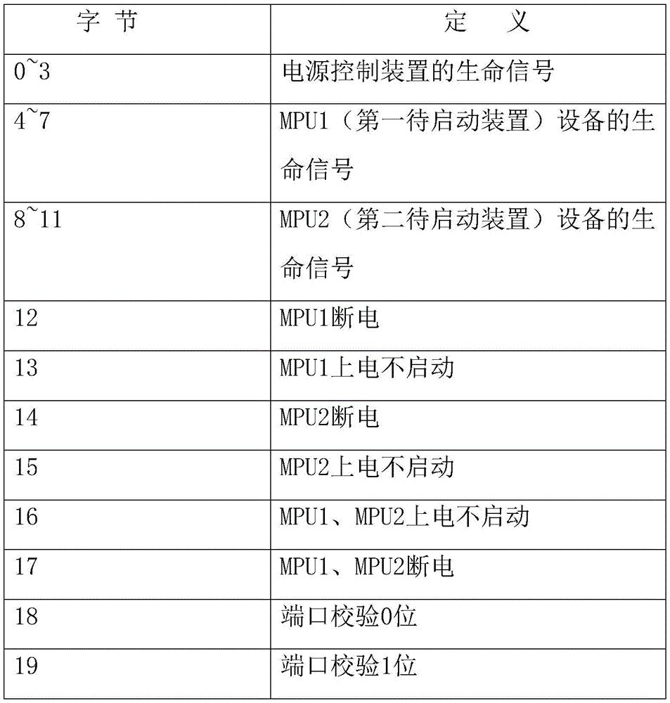
In this configuration, a signal (vital signal) for indicating that the device is normally operating occupies four bytes, i.e., 32 bits, and has a data length of 0 to 65535, and the remaining signals occupy one byte, i.e., 8 bits. Through a great deal of experiments and verification by the inventor, the second port 102 configured as above can implement stable and efficient communication with the first device to be activated 20. It is understood that the configuration of the third port 106 may be the same as the configuration of the second port 102, and will not be described herein.
In a specific application, as shown in fig. 4, a schematic structural diagram of a power control device is shown; the power supply control device is applied to locomotive control with two MPUs, wherein the area corresponding to the reference numeral 401 is a power supply access area, as shown in FIG. 4, the power supply access area can comprise two power supply access interfaces, and after the two power supply access interfaces are connected with a power supply, the two power supply access interfaces can respectively supply power to the two MPUs; the area corresponding to reference numeral 402 is a single chip microcomputer, the single chip microcomputer can integrate the functions of a timing unit and a restart signal sending unit and is responsible for processing power-on non-start fault judgment of the two MPUs and sending a restart signal, the area corresponding to reference numeral 403 is an interface area, and communication between the power control device and the two MPUs can be realized through the two interfaces.
In a specific embodiment, the control scheme of the power control device may specifically be:
the power control device transmits a vital signal (a fifth signal) and a port check bit of the power control device to the MPU1 (a first device to be started) and the MPU2 (a second device to be started) to prove that the equipment works normally, and when the fifth signal received by the MPUs 1 and 2 is increased along with the period and the port check bit data is correct, the signal sent by the power control device is considered to be valid and reliable. Meanwhile, the power supply control device transmits the received vital signal (sixth signal) of the MPU1 to the MPU2, and transmits the vital signals (seventh signal) of the MPU2 to the MPU1, so that the MPUs 1 and 2 can know the working state of the other party when the communication between the MPUs 1 and 2 is interrupted, thereby providing multiple guarantees.
After power-on, the power control device judges the working state of the power control device through the life signal of the MPU1 and the life signal of the MPU2, and if the power control device does not receive the life signal of the MPU1 or the MPU2 after the power-on is more than 60s (preset time), the power control device considers that the power control device is not started, and restarts the MPU which is not started by power-on. For example, taking the case that the MPU1 is powered on and not started as an example, the MPU1 initial flag position 1 which is powered on and not started is subjected to power-off restart on the MPU1 which is not started after receiving a restart confirmation signal of the MPU2, and simultaneously the state of the MPU1 which is restarted is fed back, and if the MPU1 can normally work after being restarted, the MPU1 initial flag position is cleared. During the operation after that, if the MPU is restarted and also has an operation abnormality such as loss of vital sign of MPU1 due to a component failure, MPU2 may normally perform processing of redundant logic, for example, if the number of times that vital sign is lost due to a component failure in MPU1 is more than two times, replacement of MPU1 or replacement of components of MPU1 is prompted.
In summary, the power control apparatus provided in the embodiment of the present invention includes: the device comprises a first interface, a second interface, a timing unit, a restart signal sending unit and a first switch unit; the first interface is in communication connection with the timing unit; the second interface is in communication connection with the restart signal sending unit; the timing unit is in communication connection with the restart signal sending unit; the restart signal sending unit is electrically connected with the first interface of the first switch unit and is used for accessing a power supply; the second interface is used for accessing the first device to be started and receiving a first signal of the first device to be started, wherein the first signal is used for indicating that the first device to be started is in a starting state; the timing unit is used for timing after the power supply accessed by the first interface is electrified; the restarting signal sending unit is used for sending a second signal if a first signal of a first device to be started is not received at the second interface under the condition that the timing duration of the timing unit exceeds the preset duration, and the second signal is used for indicating the first switch unit to restart the first device to be started; and the first switching unit is used for accessing the first device to be started and executing the restarting operation of the first device to be started under the condition of receiving the second signal. When the power control device controls the locomotive to work based on the embodiment of the invention, the timing unit performs timing after the power supply accessed by the first interface is powered on, if the timing duration exceeds the preset duration, and the second interface does not receive the first starting signal of the first device to be started, the situation that the first device to be started is not powered on can be described, therefore, the first restarting signal can be sent to the first switch unit through the restarting signal sending unit, the first switch unit further executes the restarting operation of the first device to be started, the whole restarting process is automatically performed, and no operation is required to be performed by an operator, so that the operation of the operator on the phenomenon that the first device to be started is not powered on can be simplified.
In specific application, the embodiment of the invention also provides a power supply, which comprises any one of the power supply control devices.
The embodiment of the invention can be modified on the existing 110v power module, and changes the current situation that the existing power module only has a power supply function, so that the existing power module becomes a more intelligent power supply module capable of assisting judgment. It can be understood that, because the embodiment of the present invention adds a power supply control device in the power supply module, assuming that the power supply control module needs a working voltage of 5V, a voltage conversion module may be further disposed in the power supply module, for example, a voltage of 110V is converted into a voltage of 5V, so as to supply 5V of power to the power supply control device.
In summary, the power supply of the embodiment of the invention can be modified based on the existing power supply module, is simple and convenient to construct, and can be used for batch modification, and meanwhile, the control unit of the invention can judge the condition that the power supply is not started, assist the MPU in judging the actual condition of the fault MPU, and reduce the blind replacement of accessories caused by misjudgment.
Finally, it should be noted that: the above embodiments are only used to illustrate the technical solution of the present invention, and not to limit the same; while the invention has been described in detail and with reference to the foregoing embodiments, it will be understood by those skilled in the art that: the technical solutions described in the foregoing embodiments may still be modified, or some or all of the technical features may be equivalently replaced; and these modifications or substitutions do not depart from the spirit of the corresponding technical solutions of the embodiments of the present invention.
Claims (7)
1. A power supply control apparatus, characterized in that the apparatus comprises: the device comprises a first interface, a second interface, a timing unit, a restart signal sending unit and a first switch unit;
wherein the first interface is in communication connection with the timing unit; the second interface is in communication connection with the restart signal sending unit; the timing unit is in communication connection with the restart signal sending unit; the restarting signal sending unit is electrically connected with the first switch unit;
the first interface is used for accessing a power supply;
the second interface is used for accessing a first device to be started and receiving a first signal of the first device to be started; the first signal is used for indicating that the first device to be started is in a starting state;
the timing unit is used for timing after the power supply accessed by the first interface is powered on;
the restart signal sending unit is used for sending a second signal if the first signal of the first device to be started is not received at the second interface under the condition that the timing duration of the timing unit exceeds a preset duration; the second signal is used for indicating the first switching unit to restart the first device to be started;
the first switch unit is used for accessing the first device to be started and executing the restarting operation of the first device to be started under the condition of receiving the second signal;
the first switching unit includes: a first relay;
further comprising: a third interface and a second switching unit;
the third interface is in communication connection with the restart signal sending unit; the restart signal sending unit is also electrically connected with the second switch unit;
the third interface is used for accessing a second device to be started and receiving a third signal of the second device to be started; the third signal is used for indicating that the second device to be started is in a starting state;
the restart signal sending unit is further configured to send a fourth signal if the second start information of the second device to be started is not received at the third interface under the condition that the timing duration of the timing unit exceeds a preset duration; the fourth signal is used for indicating the second switch unit to restart the second device to be started;
the second switch unit is used for accessing the second device to be started and executing the restarting operation of the second device to be started under the condition of receiving the fourth signal;
the first device to be started is a first central control unit, and the first central control unit is used as a main control device for controlling the vehicle to run; the second device to be started is a second central control unit, and the second central control unit is used as a redundant device to assist in controlling the vehicle to run;
the power supply control device further includes:
the fifth signal generating unit is used for generating a fifth signal, wherein the fifth signal is a life signal of the power supply control device and is used for indicating that the power supply control device operates normally; the second interface is further configured to send the fifth signal to the first device to be started;
the power control device transmits a fifth signal and a port check bit to the first device to be started and the second device to be started to prove that the self equipment works normally, and when the fifth signal received by the first device to be started and the second device to be started increases with the period and the port check bit data is correct, the signal sent by the power control device is considered to be valid and reliable; meanwhile, the power supply control device transmits the received vital signal of the first device to be started to the second device to be started, transmits the vital signal of the second device to be started to the first device to be started, and enables the first device to be started and the second device to be started to know the working state of the other party when the communication between the first device to be started and the second device to be started is interrupted;
after being powered on, the power supply control device judges the working state of the first device to be started through the vital signal of the first device to be started and the vital signal of the second device to be started, and if the power supply is powered on for more than a preset time, the power supply control device does not receive the vital signal of the first device to be started or the second device to be started, and the power supply control device considers that the power supply is not started;
if the power control device considers that the first device to be started is not started after being powered on, the first device to be started which is not started after being powered on is subjected to outage restarting after receiving a restarting confirmation signal of the second device to be started, the state of the restarted first device to be started is fed back, and if the first device to be started can normally work after being restarted, the initial mark position of the first device to be started is cleared; in the subsequent operation process, if the first to-be-started device is restarted and the vital signal of the first to-be-started device is lost due to the abnormal work, the second to-be-started device normally performs the processing of redundant logic;
if the power control device considers that the second device to be started is powered on and not started, the power-off restarting of the second device to be started which is not powered on is carried out on the initial mark position 1 of the second device to be started after a restarting confirmation signal of the first device to be started is received, meanwhile, the state of the restarted second device to be started is fed back, and if the second device to be started can normally work after being restarted, the initial mark position of the second device to be started is cleared; in the subsequent operation process, if the second device to be started is restarted and the vital signal of the second device to be started is lost due to the abnormal work, the first device to be started normally carries out the processing of redundant logic.
2. The power supply control device according to claim 1,
the third interface is further configured to send the fifth signal to the second device to be started.
3. The power control device of claim 1, wherein the second interface comprises: thirty-two pins; wherein, in the thirty-two pins,
the first to fourth pins are configured as pins that transmit the fifth signal;
the fifth pin to the eighth pin are configured as pins for transmitting a sixth signal, and the sixth signal is used for indicating that the first device to be started operates normally;
the ninth pin to the twelfth pin are configured as pins for transmitting a seventh signal, and the seventh signal is used for indicating that the second device to be started operates normally;
the thirteenth pin is configured as a pin for transmitting an eighth signal, wherein the eighth signal is used for indicating the power-off fault of the first device to be started;
the fourteenth pin is configured as a pin for transmitting a ninth signal, and the ninth signal is used for indicating that the first device to be started is not started after being powered on;
the fifteenth pin is a pin configured to transmit a tenth signal, wherein the tenth signal is used for indicating the power-off fault of the second device to be started;
the sixteenth pin is a pin configured to transmit an eleventh signal, where the eleventh signal is used to indicate that the second device to be started is not started after being powered on;
the seventeenth pin is a pin configured to transmit a twelfth signal, where the twelfth signal is used to indicate that the first device to be started and the second device to be started are both powered off and failed;
the eighteenth pin is configured as a pin for transmitting a thirteenth signal, wherein the thirteenth signal is used for indicating that the first device to be started and the second device to be started are both powered on and not started;
the nineteenth pin is configured as a pin of the port check 0 bit;
the twentieth pin is configured as a port check 1-bit pin;
the twenty-first pin to the thirty-second pin are vacant pins.
4. The power control device according to any one of claims 1 to 3, wherein the second interface is an interface for communication based on a multifunction vehicle bus MVB communication system.
5. The power control device according to any one of claims 1 to 3, wherein the third interface is an interface for communication based on a multifunction vehicle bus MVB communication system.
6. The power supply control device according to any one of claims 1 to 3, wherein the second switching unit includes: and a second relay.
7. A power supply comprising a power supply control device as claimed in any one of claims 1 to 6.
Priority Applications (1)
| Application Number | Priority Date | Filing Date | Title |
|---|---|---|---|
| CN201910302852.9A CN111830889B (en) | 2019-04-16 | 2019-04-16 | Power supply control device and power supply |
Applications Claiming Priority (1)
| Application Number | Priority Date | Filing Date | Title |
|---|---|---|---|
| CN201910302852.9A CN111830889B (en) | 2019-04-16 | 2019-04-16 | Power supply control device and power supply |
Publications (2)
| Publication Number | Publication Date |
|---|---|
| CN111830889A CN111830889A (en) | 2020-10-27 |
| CN111830889B true CN111830889B (en) | 2022-08-19 |
Family
ID=72915151
Family Applications (1)
| Application Number | Title | Priority Date | Filing Date |
|---|---|---|---|
| CN201910302852.9A Active CN111830889B (en) | 2019-04-16 | 2019-04-16 | Power supply control device and power supply |
Country Status (1)
| Country | Link |
|---|---|
| CN (1) | CN111830889B (en) |
Citations (4)
| Publication number | Priority date | Publication date | Assignee | Title |
|---|---|---|---|---|
| CN204705835U (en) * | 2015-06-26 | 2015-10-14 | 安徽江淮汽车股份有限公司 | A kind of power-supply controller of electric of automobile-used igniting |
| CN106200453A (en) * | 2015-06-01 | 2016-12-07 | 三菱电机株式会社 | Vehicular electronic control unit |
| WO2018078870A1 (en) * | 2016-10-31 | 2018-05-03 | 新電元工業株式会社 | Control apparatus and method for controlling control apparatus |
| CN108614497A (en) * | 2018-06-20 | 2018-10-02 | 国家电网公司 | A kind of charging pile remote reboot and stop power transmission warning device |
Family Cites Families (8)
| Publication number | Priority date | Publication date | Assignee | Title |
|---|---|---|---|---|
| JP5068186B2 (en) * | 2008-01-11 | 2012-11-07 | 富士通コンポーネント株式会社 | Power supply control device and program |
| CN103455005B (en) * | 2013-09-06 | 2015-07-22 | 北京四方继保自动化股份有限公司 | Controller redundancy and switching method |
| CN104049702A (en) * | 2014-06-16 | 2014-09-17 | 京信通信系统(中国)有限公司 | Single chip microcomputer-based CPU (Central Processing Unit) reset control system, method and device |
| CN204808188U (en) * | 2015-06-15 | 2015-11-25 | 龙芯中科技术有限公司 | Mainboard restarts system |
| CN105527914A (en) * | 2016-01-19 | 2016-04-27 | 杭州义益钛迪信息技术有限公司 | Double-CPU reliably-designed base station power environment monitoring device and method |
| IT201600117298A1 (en) * | 2016-11-21 | 2018-05-21 | Pizzato Elettrica Srl | SECURITY SWITCH WITH DIFFERENTIATED CPU |
| JP6723941B2 (en) * | 2017-02-15 | 2020-07-15 | 株式会社デンソーテン | Control device and control program updating method |
| CN108897248A (en) * | 2018-06-07 | 2018-11-27 | 浙江国自机器人技术有限公司 | A kind of self―tuning control and mobile robot |
-
2019
- 2019-04-16 CN CN201910302852.9A patent/CN111830889B/en active Active
Patent Citations (4)
| Publication number | Priority date | Publication date | Assignee | Title |
|---|---|---|---|---|
| CN106200453A (en) * | 2015-06-01 | 2016-12-07 | 三菱电机株式会社 | Vehicular electronic control unit |
| CN204705835U (en) * | 2015-06-26 | 2015-10-14 | 安徽江淮汽车股份有限公司 | A kind of power-supply controller of electric of automobile-used igniting |
| WO2018078870A1 (en) * | 2016-10-31 | 2018-05-03 | 新電元工業株式会社 | Control apparatus and method for controlling control apparatus |
| CN108614497A (en) * | 2018-06-20 | 2018-10-02 | 国家电网公司 | A kind of charging pile remote reboot and stop power transmission warning device |
Also Published As
| Publication number | Publication date |
|---|---|
| CN111830889A (en) | 2020-10-27 |
Similar Documents
| Publication | Publication Date | Title |
|---|---|---|
| US10824212B2 (en) | Power feeding system and negotiation controller | |
| KR970068366A (en) | Bus-network operation of electronic devices with microcontrollers | |
| US20130285445A1 (en) | Circuit Arrangement Comprising a Monitoring Device | |
| US10497189B2 (en) | Vehicular control device and method of controlling vehicular control device | |
| JPH09212261A (en) | Power control system for information processing equipment | |
| US20130215549A1 (en) | Power-supply control device | |
| CN111830889B (en) | Power supply control device and power supply | |
| CN114168395A (en) | Chip power-on control method, control device and storage medium | |
| CN113839429A (en) | Vehicle-mounted inverter and vehicle-mounted power supply system | |
| JPWO2014106889A1 (en) | Battery control device | |
| KR102029371B1 (en) | Power Supply system and method for ethernet communication network in vehicle | |
| JP6036229B2 (en) | Battery control device, battery control method, and program | |
| CN214011939U (en) | Power board, single board, power supply unit | |
| US9483105B2 (en) | Communication system and electronic control unit | |
| JP2011227786A (en) | Microcomputer control system, charging device using the same and photovoltaic power supply system | |
| CN114335764A (en) | Control method and device, energy storage system and non-volatile computer readable storage medium | |
| US20250123668A1 (en) | Communication system and electronic control device | |
| KR20220009250A (en) | Apparatus and method for controlling electric power of vehicle | |
| CN112783308A (en) | Power panel, single board, power device and power management method | |
| KR102722600B1 (en) | Power stabilizing apparatus for power distribution and monitoring of electric buses | |
| CN119376317B (en) | Control method and device for bus device power supply, storage medium and electronic device | |
| US11048324B2 (en) | Method for controlling a low consumption mode of an electronic circuit unit, control device, and motor vehicle | |
| CN112721639A (en) | Relay control method and device | |
| CN215895346U (en) | Electric sequential control circuit | |
| JP2001077876A (en) | Power supply control system |
Legal Events
| Date | Code | Title | Description |
|---|---|---|---|
| PB01 | Publication | ||
| PB01 | Publication | ||
| SE01 | Entry into force of request for substantive examination | ||
| SE01 | Entry into force of request for substantive examination | ||
| GR01 | Patent grant | ||
| GR01 | Patent grant |