CN111804690A - Test tube cleaning mechanism for water quality testing equipment and water quality testing equipment - Google Patents
Test tube cleaning mechanism for water quality testing equipment and water quality testing equipment Download PDFInfo
- Publication number
- CN111804690A CN111804690A CN202010670218.3A CN202010670218A CN111804690A CN 111804690 A CN111804690 A CN 111804690A CN 202010670218 A CN202010670218 A CN 202010670218A CN 111804690 A CN111804690 A CN 111804690A
- Authority
- CN
- China
- Prior art keywords
- test tube
- rack
- clamping
- water quality
- quality testing
- Prior art date
- Legal status (The legal status is an assumption and is not a legal conclusion. Google has not performed a legal analysis and makes no representation as to the accuracy of the status listed.)
- Granted
Links
Images


Classifications
-
- B—PERFORMING OPERATIONS; TRANSPORTING
- B08—CLEANING
- B08B—CLEANING IN GENERAL; PREVENTION OF FOULING IN GENERAL
- B08B9/00—Cleaning hollow articles by methods or apparatus specially adapted thereto
- B08B9/08—Cleaning containers, e.g. tanks
- B08B9/20—Cleaning containers, e.g. tanks by using apparatus into or on to which containers, e.g. bottles, jars, cans are brought
- B08B9/28—Cleaning containers, e.g. tanks by using apparatus into or on to which containers, e.g. bottles, jars, cans are brought the apparatus cleaning by splash, spray, or jet application, with or without soaking
-
- B—PERFORMING OPERATIONS; TRANSPORTING
- B08—CLEANING
- B08B—CLEANING IN GENERAL; PREVENTION OF FOULING IN GENERAL
- B08B13/00—Accessories or details of general applicability for machines or apparatus for cleaning
-
- F26B21/50—
-
- G—PHYSICS
- G01—MEASURING; TESTING
- G01N—INVESTIGATING OR ANALYSING MATERIALS BY DETERMINING THEIR CHEMICAL OR PHYSICAL PROPERTIES
- G01N21/00—Investigating or analysing materials by the use of optical means, i.e. using sub-millimetre waves, infrared, visible or ultraviolet light
- G01N21/75—Systems in which material is subjected to a chemical reaction, the progress or the result of the reaction being investigated
- G01N21/77—Systems in which material is subjected to a chemical reaction, the progress or the result of the reaction being investigated by observing the effect on a chemical indicator
- G01N21/78—Systems in which material is subjected to a chemical reaction, the progress or the result of the reaction being investigated by observing the effect on a chemical indicator producing a change of colour
-
- G—PHYSICS
- G01—MEASURING; TESTING
- G01N—INVESTIGATING OR ANALYSING MATERIALS BY DETERMINING THEIR CHEMICAL OR PHYSICAL PROPERTIES
- G01N35/00—Automatic analysis not limited to methods or materials provided for in any single one of groups G01N1/00 - G01N33/00; Handling materials therefor
- G01N35/0099—Automatic analysis not limited to methods or materials provided for in any single one of groups G01N1/00 - G01N33/00; Handling materials therefor comprising robots or similar manipulators
-
- G—PHYSICS
- G01—MEASURING; TESTING
- G01N—INVESTIGATING OR ANALYSING MATERIALS BY DETERMINING THEIR CHEMICAL OR PHYSICAL PROPERTIES
- G01N35/00—Automatic analysis not limited to methods or materials provided for in any single one of groups G01N1/00 - G01N33/00; Handling materials therefor
- G01N35/02—Automatic analysis not limited to methods or materials provided for in any single one of groups G01N1/00 - G01N33/00; Handling materials therefor using a plurality of sample containers moved by a conveyor system past one or more treatment or analysis stations
- G01N35/04—Details of the conveyor system
- G01N2035/0401—Sample carriers, cuvettes or reaction vessels
- G01N2035/0437—Cleaning cuvettes or reaction vessels
Landscapes
- Physics & Mathematics (AREA)
- Chemical & Material Sciences (AREA)
- General Health & Medical Sciences (AREA)
- General Physics & Mathematics (AREA)
- Life Sciences & Earth Sciences (AREA)
- Pathology (AREA)
- Analytical Chemistry (AREA)
- Biochemistry (AREA)
- Engineering & Computer Science (AREA)
- Health & Medical Sciences (AREA)
- Immunology (AREA)
- Robotics (AREA)
- Mechanical Engineering (AREA)
- Chemical Kinetics & Catalysis (AREA)
- Plasma & Fusion (AREA)
- Sampling And Sample Adjustment (AREA)
- Automatic Analysis And Handling Materials Therefor (AREA)
Abstract
本申请公开了水质检测设备的试管清洗机构以及水质检测设备,其中,试管清洗机构包括:存储架,转动安装在机架上,存储架的上端面具有多个固定槽;试管自夹紧套,固定安装在固定槽中;旋转驱动件,用于驱动存储架转动;清洗架,位于存储架的下方,清洗架上安装有多个喷水头;第一往复元件,用于驱动清洗架往复移动,使水喷向固定在试管自夹紧套上的试管;风干架,位于存储架的下方,风干架上安装有多个吹风头;第二往复元件,用于驱动风干架往复移动,使风喷向固定在试管自夹紧套上的试管;废液盒,位于存储架的下方,用于接收废水。本申请的试管清洗机构能够对试管进行自动清洗。
The present application discloses a test tube cleaning mechanism for water quality testing equipment and water quality testing equipment, wherein the test tube cleaning mechanism includes: a storage rack, which is rotatably mounted on the rack, and the upper end surface of the storage rack has a plurality of fixing grooves; the test tube self-clamping sleeve, It is fixedly installed in the fixing groove; the rotary driving part is used to drive the storage rack to rotate; the cleaning rack is located under the storage rack, and a plurality of water spray heads are installed on the cleaning rack; the first reciprocating element is used to drive the cleaning rack to move back and forth , so that the water is sprayed to the test tube fixed on the self-clamping sleeve of the test tube; the air drying rack is located under the storage rack, and a plurality of hair dryers are installed on the air drying rack; the second reciprocating element is used to drive the air drying rack to move back and forth, so that the air Spray to the test tube fixed on the self-clamping sleeve of the test tube; the waste liquid box, located under the storage rack, is used to receive the waste water. The test tube cleaning mechanism of the present application can automatically clean the test tube.
Description
技术领域technical field
本发明涉及水质检测领域,具体涉及水质检测设备的试管清洗机构以及水质检测设备。The invention relates to the field of water quality detection, in particular to a test tube cleaning mechanism of water quality detection equipment and water quality detection equipment.
背景技术Background technique
市政污水厂等地方需要化验员每日对污水进出水样进行检测,比如进行COD、BOD、总氮、总磷等指标的检测,通过人工检测的方式成本较高,而且由于人工操作的误差及不确定性较多,检测结果的准确性不佳。In municipal sewage plants and other places, laboratory technicians are required to test the incoming and outgoing water samples of sewage, such as COD, BOD, total nitrogen, total phosphorus and other indicators. There are many uncertainties, and the accuracy of the detection results is not good.
为了解决上述问题,可以采用自动化设备辅助检测,自动化设备通常包括试管架,试管架上的试管使用后需要人工取出进行清洗,较为繁琐。In order to solve the above problems, automated equipment can be used to assist the detection. The automated equipment usually includes a test tube rack, and the test tubes on the test tube rack need to be manually removed for cleaning after use, which is cumbersome.
发明内容SUMMARY OF THE INVENTION
本发明针对上述问题,提出了水质检测设备的试管清洗机构以及水质检测设备。In view of the above problems, the present invention proposes a test tube cleaning mechanism and a water quality detection device for water quality detection equipment.
本发明采取的技术方案如下:The technical scheme adopted by the present invention is as follows:
一种水质检测设备的试管清洗机构,水质检测设备包括机架,所述试管清洗机构包括:A test tube cleaning mechanism for water quality testing equipment, the water quality testing equipment includes a rack, and the test tube cleaning mechanism includes:
存储架,转动安装在机架上,所述存储架的上端面具有多个固定槽,所述存储架具有初始工作位和清洗工作位,清洗工作位相对于初始工作位旋转180°;The storage rack is rotatably mounted on the rack, the upper end surface of the storage rack has a plurality of fixing grooves, the storage rack has an initial working position and a cleaning working position, and the cleaning working position is rotated 180° relative to the initial working position;
试管自夹紧套,固定安装在固定槽中;The test tube self-clamping sleeve is fixedly installed in the fixed groove;
旋转驱动件,用于驱动所述存储架转动;a rotary drive member for driving the storage rack to rotate;
清洗架,位于存储架的下方,清洗架上安装有多个喷水头;The cleaning rack is located below the storage rack, and a plurality of water spray heads are installed on the cleaning rack;
第一往复元件,用于驱动所述清洗架往复移动,使水喷向固定在试管自夹紧套上的试管;The first reciprocating element is used to drive the cleaning rack to reciprocate, so that water is sprayed to the test tube fixed on the self-clamping sleeve of the test tube;
风干架,位于存储架的下方,风干架上安装有多个吹风头;an air drying rack, located under the storage rack, and a plurality of hair dryers are installed on the air drying rack;
第二往复元件,用于驱动所述风干架往复移动,使风喷向固定在试管自夹紧套上的试管;The second reciprocating element is used to drive the air drying rack to reciprocate, so that the air is sprayed to the test tube fixed on the self-clamping sleeve of the test tube;
废液盒,位于存储架的下方,用于接收废水。Waste box, located under the storage rack, to receive waste water.
本申请的试管清洗机构能够对试管进行自动清洗,使用时,试管固定在试管自夹紧套上,通过旋转驱动件使存储架转动180°,从初始工作位切换至清洗工作位,此时试管的开口向下,然后第一往复元件和喷水头工作,水喷射在试管中,对试管进行清洗,废水落入废液盒内,清洗完成后第二往复元件和吹风头工作,对试管进行干燥,干燥完成后存储架旋转复位。The test tube cleaning mechanism of the present application can automatically clean the test tube. When in use, the test tube is fixed on the test tube self-clamping sleeve, and the storage rack is rotated by 180° through the rotating driving member, and the test tube is switched from the initial working position to the cleaning working position. At this time, the test tube Then the first reciprocating element and the water spray head work, the water is sprayed in the test tube, the test tube is cleaned, and the waste water falls into the waste liquid box. After drying, the storage rack is rotated and reset.
于本发明其中一实施例中,所述机架上具有避让口,所述存储架设置在避让口处。In one embodiment of the present invention, the rack has an escape opening, and the storage rack is disposed at the escape opening.
于本发明其中一实施例中,旋转驱动件为旋转气缸或者电机。In one embodiment of the present invention, the rotary driving member is a rotary cylinder or a motor.
于本发明其中一实施例中,试管清洗机构还包括与机架固定的环形或矩形的围挡,所述存储架的下端位于围挡内,所述清洗架和分干架均位于围挡的下方。In one embodiment of the present invention, the test tube cleaning mechanism further includes an annular or rectangular enclosure fixed to the rack, the lower end of the storage rack is located in the enclosure, and the cleaning rack and the drying rack are located below the enclosure. .
设置围挡能够防止水到处溅射。Set up a fence to prevent water from splashing around.
于本发明其中一实施例中,所述第一往复元件为气缸或电动推杆;所述第二往复元件为气缸或电动推杆。In one embodiment of the present invention, the first reciprocating element is an air cylinder or an electric push rod; the second reciprocating element is an air cylinder or an electric push rod.
于本发明其中一实施例中,所述试管自夹紧套包括供试管管体插入的本体,所述本体内安装有夹紧弹片,所述夹紧弹片包括向本体轴线一侧凸起的弧形部;In one embodiment of the present invention, the test tube self-clamping sleeve includes a body into which the test tube body is inserted, a clamping elastic sheet is installed in the main body, and the clamping elastic sheet includes an arc protruding toward the axis of the body. shape;
所述本体包括内套体和外套体,所述内套体上具有贯穿孔,所述夹紧弹片还包括限位部,所述限位部设置在弧形部的至少一端,所述外套体外套在内套体上且与内套体固定,所述夹紧弹片的限位部位于内套体和外套体之间,夹紧弹片的弧形部穿过所述贯穿孔。The body includes an inner sleeve body and an outer sleeve, the inner sleeve body has a through hole, the clamping elastic piece further includes a limit portion, the limit portion is arranged at at least one end of the arc portion, and the outer sleeve The outer sleeve is on and fixed with the inner sleeve body, the limiting portion of the clamping elastic sheet is located between the inner sleeve body and the outer sleeve body, and the arc portion of the clamping elastic sheet passes through the through hole.
试管管体插入本体时,能够压缩弧形部,被挤压变形后的弧形部能够对试管管体的外侧壁施加作用力,从而能够防止试管管体脱离本体,本申请的试管自夹紧套能够对试管管体实现自夹紧功能。内套体和外套体的这种设计,使得安装夹紧弹片较为方便。When the test tube body is inserted into the body, the arc-shaped portion can be compressed, and the arc-shaped portion after being squeezed and deformed can exert a force on the outer wall of the test tube body, thereby preventing the test tube body from being separated from the body. The test tube self-clamping The sleeve can realize the self-clamping function of the test tube body. The design of the inner sleeve body and the outer sleeve body makes it more convenient to install and clamp the elastic pieces.
本申请还公开了一种水质检测设备,包括上文所述的试管清洗机构。The present application also discloses a water quality testing device, including the test tube cleaning mechanism described above.
于本发明其中一实施例中,还包括移动抓取机构,所述移动抓取机构包括:In one embodiment of the present invention, it further includes a mobile grabbing mechanism, and the mobile grabbing mechanism includes:
一个移动单元;a mobile unit;
安装架,安装在移动单元上;Mounting frame, mounted on the mobile unit;
第一升降元件,安装在安装架上,所述第一升降元件包括能够升降的第一驱动件;a first lifting element mounted on the mounting frame, the first lifting element comprising a first driving member capable of lifting;
第一夹紧元件,与所述第一驱动件相对固定,所述第一夹紧元件用于夹取物品;a first clamping element, which is relatively fixed with the first driving member, and the first clamping element is used for clamping objects;
第二升降元件,安装在安装架上,所述第二升降元件包括能够升降的第二驱动件;a second lifting element, mounted on the mounting frame, the second lifting element comprising a second driving member capable of lifting;
注射器组件,安装在所述安装架上,所述注射器组件能够抽取和释放液体。A syringe assembly is mounted on the mounting bracket, the syringe assembly is capable of drawing and releasing liquids.
于本发明其中一实施例中,所述移动单元为机械手。In one embodiment of the present invention, the moving unit is a manipulator.
于本发明其中一实施例中,所述移动单元包括第一直线模组、第二直线模组和第三直线模组,所述第二直线模组安装在第一直线模组的活动件上,所述第三直线模组安装在所述第二直线模组的活动件上,所述第一直线模组用于驱动所述第二直线模组沿X轴方向移动,所述第二直线模组用于驱动第三直线模组沿Y轴方向移动,所述第三直线模组的活动件能够沿Z轴方向移动,所述Z轴方向为竖直方向,所述X轴方向、Y轴方向以及Z轴方向两两相互垂直;所述安装架与所述第三直线模组的活动件固定。In one embodiment of the present invention, the moving unit includes a first linear module, a second linear module and a third linear module, and the second linear module is installed on the movable side of the first linear module. The third linear module is installed on the movable part of the second linear module, the first linear module is used to drive the second linear module to move along the X-axis direction, the The second linear module is used to drive the third linear module to move along the Y-axis direction, the movable part of the third linear module can move along the Z-axis direction, the Z-axis direction is the vertical direction, the X-axis The direction, the Y-axis direction and the Z-axis direction are perpendicular to each other; the mounting frame is fixed to the movable part of the third linear module.
本发明的有益效果是:本申请的试管清洗机构能够对试管进行自动清洗,使用时,试管固定在试管自夹紧套上,通过旋转驱动件使存储架转动180°,从初始工作位切换至清洗工作位,此时试管的开口向下,然后第一往复元件和喷水头工作,水喷射在试管中,对试管进行清洗,废水落入废液盒内,清洗完成后第二往复元件和吹风头工作,对试管进行干燥,干燥完成后存储架旋转复位。The beneficial effects of the present invention are: the test tube cleaning mechanism of the present application can automatically clean the test tube. When in use, the test tube is fixed on the test tube self-clamping sleeve, and the storage rack is rotated 180° by the rotating drive member, and is switched from the initial working position to the test tube self-clamping sleeve. Cleaning the working position, at this time the opening of the test tube is downward, and then the first reciprocating element and the water spray head work, water is sprayed in the test tube, the test tube is cleaned, and the waste water falls into the waste liquid box. After the cleaning is completed, the second reciprocating element and The hair dryer works to dry the test tube, and the storage rack rotates and resets after drying.
附图说明:Description of drawings:
图1是实施例1水质检测设备的示意图;Fig. 1 is the schematic diagram of
图2是水质检测设备隐藏部分结构后的示意图;Fig. 2 is the schematic diagram of the hidden part of the structure of the water quality testing equipment;
图3是移动抓取机构的结构示意图;Fig. 3 is the structural representation of mobile grabbing mechanism;
图4是移动抓取机构的另一角度的结构示意图;4 is a schematic structural diagram of another angle of the mobile grabbing mechanism;
图5是实施例1试管自夹紧套的示意图;Fig. 5 is the schematic diagram of
图6是实施例1试管自夹紧套的剖视图;Fig. 6 is the sectional view of
图7是实施例1试管自夹紧套的爆炸图;Fig. 7 is the exploded view of
图8是摇匀机构的示意图;Fig. 8 is the schematic diagram of shaking mechanism;
图9是倒废液机构的示意图;Fig. 9 is the schematic diagram of pouring waste liquid mechanism;
图10是具有排液漏斗的倒废液机构的示意图;Figure 10 is a schematic diagram of a waste liquid pouring mechanism with a drain funnel;
图11是开关盖机构的示意图;Fig. 11 is the schematic diagram of opening and closing cover mechanism;
图12是水质检测部分内部结构示意图;Figure 12 is a schematic diagram of the internal structure of the water quality detection part;
图13是加药机构的示意图;Figure 13 is a schematic diagram of a dosing mechanism;
图14是清洗箱的示意图;Figure 14 is a schematic view of a cleaning tank;
图15是比色皿夹紧元件的示意图;Figure 15 is a schematic view of a cuvette clamping element;
图16是比色皿夹紧元件夹紧比色皿后的示意图;Fig. 16 is the schematic diagram after the cuvette clamping element clamps the cuvette;
图17是实施例2摇匀加热机构的示意图;Fig. 17 is the schematic diagram of
图18是实施例2试管自夹紧套的示意图;Fig. 18 is the schematic diagram of
图19是实施例3试管组件的爆炸图;Figure 19 is an exploded view of the test tube assembly of Example 3;
图20是实施例3试管组件的剖视图;Figure 20 is a cross-sectional view of the test tube assembly of Example 3;
图21是实施例4水质检测设备的示意图Figure 21 is a schematic diagram of the water quality testing equipment in Example 4
图22是省略磁力搅拌器后搅拌机构与样品杯的示意图Figure 22 is a schematic diagram of the stirring mechanism and the sample cup after omitting the magnetic stirrer
图23是样品杯输送机构、搅拌机构和注射器清洗机构在机架上的示意图;Figure 23 is a schematic diagram of the sample cup conveying mechanism, the stirring mechanism and the syringe cleaning mechanism on the rack;
图24是样品杯输送机构、搅拌机构和注射器清洗机构在机架上的另一角度的示意图Figure 24 is a schematic diagram of another angle of the sample cup conveying mechanism, stirring mechanism and syringe cleaning mechanism on the frame
图25是省略磁力搅拌器后搅拌机构的示意图Figure 25 is a schematic diagram of the stirring mechanism after omitting the magnetic stirrer
图26是省略磁力搅拌器后搅拌机构的剖视图;Figure 26 is a cross-sectional view of the stirring mechanism after the magnetic stirrer is omitted;
图27是注射器清洗机构的剖视图;Figure 27 is a cross-sectional view of the syringe cleaning mechanism;
图28是实施例5试管清洗机构的示意图;Figure 28 is a schematic diagram of the test tube cleaning mechanism in Example 5;
图29是实施例5试管清洗机构另一角度的示意图。FIG. 29 is a schematic diagram of another angle of the test tube cleaning mechanism in Example 5. FIG.
图中各附图标记为:The reference numbers in the figure are:
1、机架;2、存储架;3、移动抓取机构;4、开关盖机构;5、加药机构;6、摇匀机构;7、消解仪;8、检测仪;9、移动单元;10、抓取组件;11、安装架;12、第一升降元件;14、第一夹紧元件;16、活动杆;17、安装块;18、L型板;19、第一导轨;20、竖直部;21、水平部;22、第一直线模组;23、第二直线模组;24、第三直线模组;25、第二升降元件;26、第二驱动件;27、注射器组件;28、安装部;29、伺服电机;30、夹紧气缸;31、支架;32、电感式接近传感器;33、药剂瓶;34、出药架;35、安装孔;36、蠕动泵;37、换药驱动组件;38、主动轮;39、从动轮;40、传动带;41、移动块;42、切换电机;43、第一旋转元件;44、第二旋转元件;45、试管自夹紧套;46、试管管体;47、本体;48、夹紧弹片;49、弧形部;50、内套体;51、外套体;52、贯穿孔;53、限位部;54、限位槽;55、限位台阶;56、倒废液机构;57、旋转倒液元件;58、第二夹紧元件;59、排液架;60、排液孔;61、切换元件;62、废液罐;63、排液漏斗;64、旋转换位元件;65、比色皿夹紧元件;66、比色皿;67、清洗箱;68、清洗槽;69、清洗喷头;70、加热元件;71、试管盖;72、内插部;73、外套部;74、环形槽;75、第一锥形导向面;76、第二锥形导向面;77、夹持部;78、轨道;79、样品杯输送机构;80、搅拌机构;81、注射器清洗机构;82、样品杯;83、取样位;84、输入组件;85、输出组件;86、推杯元件;87、架子;88、滚轮;89、输送带;90、容纳槽;91、输送带驱动电机;92、凹口;93、平直侧壁;94、圆弧形侧壁;95、弧形限位块;96、限位块驱动气缸;97、环形铁片;98、调位旋转件;99、弧形推板;100、磁力搅拌器;101、输送管;102、储料部;103、输送部;104、条形口;105、磁性棒;106、第一阻挡片;107、第一阻挡片驱动气缸;108、第二阻挡片;109、第二阻挡片驱动气缸;110、第二阻挡片升降气缸;111、输送管升降元件;112、距离传感器;113、输送管转动元件;114、安装板;115、循环箱;116、过滤层;117、上层;118、下层;119、水泵;120、探测传感器;121、试管清洗机构;122、固定槽;123、旋转驱动件;124、清洗架;125、喷水头;126、第一往复元件;127、风干架;128、吹风头;129、第二往复元件;130、废液盒;131、避让口;132、围挡;133、出水管。1. Rack; 2. Storage rack; 3. Mobile grabbing mechanism; 4. Opening and closing cover mechanism; 5. Dosing mechanism; 6. Shaking mechanism; 7. Digestion apparatus; 8. Detector; 9. Mobile unit; 10. Grab assembly; 11. Mounting frame; 12. First lifting element; 14. First clamping element; 16. Active rod; 17. Mounting block; 18. L-shaped plate; 19. First rail; 20, vertical part; 21, horizontal part; 22, first linear module; 23, second linear module; 24, third linear module; 25, second lifting element; 26, second driving part; 27, Syringe assembly; 28, mounting part; 29, servo motor; 30, clamping cylinder; 31, bracket; 32, inductive proximity sensor; 33, medicine bottle; 34, medicine dispensing rack; 35, mounting hole; 36, peristaltic pump ; 37, dressing change drive assembly; 38, driving wheel; 39, driven wheel; 40, transmission belt; 41, moving block; 42, switching motor; 43, first rotating element; 44, second rotating element; 45, test tube self Clamping sleeve; 46, test tube body; 47, body; 48, clamping shrapnel; 49, arc part; 50, inner sleeve body; 51, outer sleeve; 52, through hole; 53, limit part; 54, Limit groove; 55, Limit step; 56, Waste liquid pouring mechanism; 57, Rotary liquid pouring element; 58, Second clamping element; 59, Drain rack; 60, Drain hole; 61, Switch element; 62 , waste liquid tank; 63, drain funnel; 64, rotary transposition element; 65, cuvette clamping element; 66, cuvette; 67, cleaning box; 68, cleaning tank; 69, cleaning nozzle; 70, Heating element; 71, test tube cover; 72, inner part; 73, outer part; 74, annular groove; 75, first tapered guide surface; 76, second tapered guide surface; 77, clamping part; 78, track; 79, sample cup conveying mechanism; 80, stirring mechanism; 81, syringe cleaning mechanism; 82, sample cup; 83, sampling position; 84, input assembly; 85, output assembly; 86, push cup element; 87, shelf; 88, roller; 89, conveyor belt; 90, accommodating groove; 91, conveyor belt drive motor; 92, notch; 93, straight side wall; 94, arc-shaped side wall; 95, arc limit block; 96 , Limit block driving cylinder; 97, Ring iron plate; 98, Adjustment rotating part; 99, Arc push plate; 100, Magnetic stirrer; 101, Conveying pipe; 102, Material storage part; 103, Conveying part; 104 105, magnetic rod; 106, the first blocking piece; 107, the first blocking piece driving cylinder; 108, the second blocking piece; 109, the second blocking piece driving cylinder; 110, the second blocking piece lifting cylinder ; 111, conveying pipe lifting element; 112, distance sensor; 113, conveying pipe rotating element; 114, mounting plate; 115, circulation box; 116, filter layer; 117, upper layer; 118, lower layer; 119, water pump; sensor; 121, test tube cleaning mechanism; 122, fixed groove; 123, rotation 124, cleaning rack; 125, water spray head; 126, first reciprocating element; 127, air drying rack; 128, blowing head; 129, second reciprocating element; 130, waste liquid box; 131, escape port; 132 , enclosure; 133, outlet pipe.
具体实施方式:Detailed ways:
下面结合各附图,对本发明做详细描述。The present invention will be described in detail below with reference to the accompanying drawings.
实施例1Example 1
如图1~13所示,一种水质检测设备,能够自动化的对水质进行检测,包括机架1,机架1上安装有;As shown in Figures 1 to 13, a water quality testing equipment, capable of automatically testing water quality, includes a
存储架2,用于安放试管和比色皿66;
移动抓取机构3,用于抓取物品以及抽取样品;Move the
开关盖机构4,用于打开或关闭试管的试管盖71;The opening and closing cover mechanism 4 is used to open or close the
加药机构5,用于向试管管体46内加注药剂;The
摇匀机构6,用于使样品和药剂充分混合;Shaking
消解仪7,用于对摇匀后的液体进行加热消解;Digestion apparatus 7, used to heat and digest the shaken liquid;
检测仪8,用于对比色皿66内的液体进行检测。The
如图2、3和4所示,于本实施例中,移动抓取机构3包括:As shown in Figures 2, 3 and 4, in this embodiment, the
一个移动单元9;a
安装架11,安装在移动单元9上;The mounting
第一升降元件12,安装在安装架11上,第一升降元件12包括能够升降的第一驱动件;The
第一夹紧元件14,与第一驱动件相对固定,第一夹紧元件14用于夹取物品;The
第二升降元件25,安装在安装架11上,第二升降元件25包括能够升降的第二驱动件26;The
注射器组件27,安装在安装架11上,注射器组件27能够抽取和释放液体。A
安装架11上安装了第一升降元件12和第二升降元件25,且第一升降元件12能够控制第一夹紧元件14升降,第二升降元件25能够控制注射器组件27升降,只需要一个移动单元9就能够实现抓取物品和抽取样品的操作,整个结构更紧凑。The
实际运用时,注射器组件27可以采用现有的电动注射器。注射器组件27包括针筒、与针筒下端连接的针头、滑动设置在针筒内的活塞以及驱动活塞往复移动的电动机构。In practical use, the
于本实施例中,安装架11包括两个相互垂直的安装部28,第一升降元件12和第二升降元件25分别安装在两个安装部28上。相互垂直的安装部28的设计,方便安装第一升降元件12和第二升降元件25。In this embodiment, the mounting
于本实施例中,第一驱动件上安装有重力传感器(图中未示出),第一夹紧元件14的上端与重力传感器固定。实际运用时,移动抓取机构3还包括控制器和报警单元,控制器和重力传感器以及报警单元电连接。报警单元可以包括喇叭、报警灯等结构。In this embodiment, a gravity sensor (not shown in the figure) is installed on the first driving member, and the upper end of the
通过重力传感器能够反馈力的信号,使设备运行更可靠。第一夹紧元件14每次夹取试管、比色皿66等物品时都有对应的重量数据,从而反馈给控制器,能够判断是否夹取成功。如果在夹取后重量出现较大误差,或者在正常运行过程中突然重力传感器上有较大的力传来(比如第一夹紧元件14撞击到物体),控制器能够判断出现异常,并控制报警单元工作。The force signal can be fed back through the gravity sensor, which makes the equipment operate more reliably. Each time the
实际运用时,移动单元9为机械手。于本实施例中,移动单元9包括第一直线模组22、第二直线模组23和第三直线模组24,第二直线模组23安装在第一直线模组22的活动件上,第三直线模组24安装在第二直线模组23的活动件上,第一直线模组22用于驱动第二直线模组23沿X轴方向移动,第二直线模组23用于驱动第三直线模组24沿Y轴方向移动,第三直线模组24的活动件能够沿Z轴方向移动,Z轴方向为竖直方向,X轴方向、Y轴方向以及Z轴方向两两相互垂直;安装架11与第三直线模组24的活动件固定。In actual use, the moving
实际运用时,直线模组可以为滚珠丝杆副、齿条齿轮等现有的结构。In practical application, the linear module can be an existing structure such as a ball screw pair, a rack and pinion, etc.
于本实施例中,第一升降元件12和第二升降元件25均为伸缩气缸。In this embodiment, the
于本实施例中,第一夹紧元件14为夹爪气缸。夹爪气缸又叫气动手指、气动夹爪或气动夹指。In this embodiment, the
实际运用时,第一驱动件可以为活动杆16,活动杆16的端部具有安装块17,重力传感器安装在安装块17上。于本实施例中,第一升降元件12的侧壁具有第一导轨19,第一驱动件包括活动杆16和L型板18,L型板18的竖直部20与第一导轨19滑动配合,L型板18的水平部21与活动杆16固定,重力传感器安装在水平部21的上。通过第一导轨19和竖直部20的配合,在活动杆16活动时,能够可靠的驱动L型板18移动,运动结构安全可靠。In practice, the first driving member may be a
本实施例中,安装架11、第一升降元件12、重力传感器以及第一夹紧元件14能够形成抓取物品的抓取组件10。In this embodiment, the mounting
如图6所示,本实施例的试管包括试管本体47和试管盖71,试管本体47与试管盖71螺纹连接。如图11和12所示,于本实施例中,开关盖机构4包括:As shown in FIG. 6 , the test tube of this embodiment includes a
移动单元9;
抓取组件10,安装在移动单元9上,能够夹紧物品并带动物品上下移动;The grabbing
伺服电机29;
夹紧气缸30,安装在伺服电机29的转动轴上,用于夹紧试管管体46。The clamping
开关盖机构4能够自动实现打开试管盖71或旋紧试管盖71。当需要开盖时,夹紧气缸30夹紧试管管体46,抓取组件10夹紧试管盖71,伺服电机29转动,同时抓取组件10带动试管盖71向上移动;当需要旋紧试管盖71时,夹紧气缸30夹紧试管管体46,抓取组件10夹紧试管盖71,伺服电机29反向转动,同时抓取组件10带动试管盖71向下移动。The opening and closing mechanism 4 can automatically open the
本实施例中,移动抓取机构3和开关盖机构4共用移动单元9和抓取组件10。In this embodiment, the moving
实际运用时,优选的,为了避免力较大时对试管造成破坏以及力较小不能达到拧紧的问题,伺服电机29采用力矩控制方式工作,电机输出恒定的旋转力,在试管盖71拧紧时,力矩大于电机输出力,电机停止运动。In practical application, it is preferred that, in order to avoid the problem of damaging the test tube when the force is large and the problem that the force cannot be tightened when the force is small, the
如图11所示,于本实施例中,伺服电机29包括支架31,支架31上安装有电感式接近传感器32,电感式接近传感器32对准夹紧气缸30,用于探测夹紧气缸30的夹爪位置。As shown in FIG. 11 , in this embodiment, the
实际运用时,夹紧气缸30的气管上安装有调压阀。通过调压阀能够调至较小的压力,来配合实现开盖或关盖的动作。In actual use, a pressure regulating valve is installed on the gas pipe of the clamping
如图2、12和13所示,于本实施例中,加药机构5包括:As shown in Figures 2, 12 and 13, in this embodiment, the
多种药剂瓶33;
出药架34,具有多个间隔设置的安装孔35;The
药管(图中省略未画出),出口端与安装孔35连接,入口端与药剂瓶33连接;The medicine tube (not shown in the figure), the outlet end is connected with the mounting
多个蠕动泵36,安装在对应的药管上;A plurality of
换药驱动组件37,用于驱动出药架34移动或转动。The medicine changing
通过设置蠕动泵36能够精确可靠的输出药剂,通过换药驱动组件37能够驱动出药架34活动,从而可以根据需要切换不同的药剂滴入试管管体46。By setting the
本申请所说的蠕动泵36安装在对应的药管上,指的是药管中间某处断开,断开处的两端分别连接蠕动泵36的两个过液孔。In this application, the
实际运用时,药管的出口端具有注射嘴,注射嘴固定在安装孔35上。In actual use, the outlet end of the medicine tube has an injection nozzle, and the injection nozzle is fixed on the
如图13所示,于本实施例中,换药驱动组件37用于驱动出药架34直线移动,换药驱动组件37包括主动轮38、从动轮39、传动带40、移动块41以及切换电机42,传动带40绕设在主动轮38和从动轮39上,切换电机42用于驱动主动轮38转动,出药架34安装在移动块41上。As shown in FIG. 13 , in this embodiment, the dressing-changing
如图12所示,于本实施例中,换药驱动组件37还包括轨道78,移动块41滑动设置在轨道78上。设置轨道78能够使移动块41可靠稳定的移动。As shown in FIG. 12 , in this embodiment, the
实际运用时,加药机构5还可以包括挡板以及驱动挡板平移的挡板驱动元件,挡板驱动元件可以为气缸等元件,在加药结束后,挡板驱动元件驱动挡板移动至出药架34的下方,防止药剂低落,污染设备。In actual use, the
如图8所示,于本实施例中,摇匀机构6包括:As shown in FIG. 8, in this embodiment, the shaking
第一旋转元件43;the first
第二旋转元件44,与第一旋转元件43的转动轴固定,第二旋转元件44的转动轴轴线与第一旋转元件43的转动轴轴线垂直;The
试管夹紧件,与第二旋转元件44的转动轴固定,试管夹紧件用于自动夹紧试管管体46。The test tube clamping piece is fixed with the rotating shaft of the second
通过第一旋转元件43和第二旋转元件44,能够带动试管夹紧件在多个维度运动,可以实现更好的摇匀操作。Through the first
实际运用时,第一旋转元件43为旋转气缸或电机;第二旋转元件44为旋转气缸或电机。In practice, the first
于本实施例中,第一旋转元件43的转动轴水平设置。In this embodiment, the rotation axis of the first
实际运用时,第一旋转元件43可以做往复摇摆动作,第二旋转元件44可以绕一个方向转动,或者往复转动。In actual use, the first
如图5、6和7所示,于本实施例中,试管夹紧件为试管自夹紧套45,试管自夹紧套45包括供试管管体46插入的本体47,本体47内安装有夹紧弹片48,夹紧弹片48包括向本体47轴线一侧凸起的弧形部49。As shown in Figures 5, 6 and 7, in this embodiment, the test tube clamping member is a test tube self-clamping
试管管体46插入本体47时,能够压缩弧形部49,被挤压变形后的弧形部49能够对试管管体46的外侧壁施加作用力,从而能够防止试管管体46脱离本体47,本申请的试管自夹紧套45能够对试管管体46实现自夹紧功能。When the
如图6和7所示,于本实施例中,本体47包括内套体50和外套体51,内套体50上具有贯穿孔52,夹紧弹片48还包括限位部53,限位部53设置在弧形部49的至少一端,外套体51外套在内套体50上且与内套体50固定,夹紧弹片48的限位部53位于内套体50和外套体51之间,夹紧弹片48的弧形部49穿过贯穿孔52。内套体50和外套体51的这种设计,使得安装夹紧弹片48较为方便。As shown in FIGS. 6 and 7 , in this embodiment, the
于本实施例中,贯穿孔52为条形孔,贯穿孔52的长度方向与内套体50的轴线方向平行。In this embodiment, the through
如图7所示,于本实施例中于,内套体50的外侧壁在贯穿孔52的两侧还具有限位槽54,夹紧弹片48的两端分别设置在对应的限位槽54中。夹紧弹片48的两端分别设置在对应的限位槽54中,指的是限位部53与限位槽54配合,这种设计既方便夹紧弹片48的安装,又能够可靠限定夹紧弹片48。As shown in FIG. 7 , in this embodiment, the outer side wall of the
实际运用时,内套体50和外套体51焊接、螺接、卡接或者通过紧固件连接。In practice, the
如图6和7所示,于本实施例中,内套体50的下部具有限位台阶55,外套体51的下端与限位台阶55相抵靠。As shown in FIGS. 6 and 7 , in this embodiment, the lower part of the
如图5和7所示,于本实施例中,夹紧弹片48有多个,绕本体47的轴线均匀设置。As shown in FIGS. 5 and 7 , in this embodiment, there are a plurality of clamping
如图12所示,水质检测设备还包括倒废液机构56。如图9和10所示,倒废液机构56包括:As shown in FIG. 12 , the water quality testing apparatus further includes a waste
旋转倒液元件57;Rotate the pouring
第二夹紧元件58,安装在旋转倒液元件57的转动轴上,用于夹紧容器;The
排液架59,具有多个排液孔60,各排液孔60用于连接不同的排液管(图中省略未画出);The
切换元件61,用于驱动排液架59移动或转动,使其中一个排液孔60接收废液。The switching
第二夹紧元件58用于夹紧带有废液的容器,通过旋转倒液元件57能够使容器倾斜,使废液落入排液架59上的排液孔60,通过切换元件61能够调节各排液孔60的位置,从而使不同的排液孔60接收废液,即可以根据废液的不同,实现分开排放或分开回收。The
本申请的容器指的是试管管体46、比色皿66等用于容纳液体的物品。The container in the present application refers to items such as the
实际运用时,旋转倒液元件57为旋转气缸或电机,旋转倒液元件57的转动轴水平设置。In practice, the rotating
于本实施例中,第二夹紧元件58为夹爪气缸。In this embodiment, the
实际运用时,切换元件61为旋转气缸或电机,切换元件61用于驱动排液架59转动。In practice, the switching
于本实施例中,切换元件61为伸缩气缸或电动推杆,切换元件61用于驱动排液架59移动。In this embodiment, the switching
如图2和12所示,于本实施例中,倒废液机构56还包括废液罐62,排液管远离排液架59的一端与对应的废液罐62连通。As shown in FIGS. 2 and 12 , in this embodiment, the waste
实际运用时,倒废液机构56还可以设置PH传感器以及用于驱动PH传感器上下移动的传感器伸缩件。通过PH传感器能够检测废液的酸碱程度,从而确定排放至哪个排液孔60,即能够实现酸液和碱液分别排放或回收。In actual use, the waste
于本实施例中,排液孔60有2个。In this embodiment, there are two drain holes 60 .
如图10所示,为了防止废液溅出,倒废液机构56还包括排液漏斗63,排液孔60位于排液漏斗63的下方,废液通过排液漏斗63后落入对应的排液孔60。As shown in FIG. 10 , in order to prevent the waste liquid from spilling out, the waste
于本实施例中,水质检测设备还包括比色皿清洗机构,如图14、15和16所示,比色皿清洗机构包括:In this embodiment, the water quality testing equipment further includes a cuvette cleaning mechanism, as shown in Figures 14, 15 and 16, the cuvette cleaning mechanism includes:
旋转换位元件64;Rotate the
比色皿66夹紧元件65,安装在旋转换位元件64的转动轴上,用于夹紧比色皿66,且比色皿66夹紧元件65夹紧比色皿66时,比色皿66的上下两端均露出比色皿66夹紧元件65;The
清洗箱67,具有多个清洗槽68,比色皿66用于倒放在清洗槽68中;The
清洗喷头69,安装在清洗槽68的底部,用于向比色皿66喷射清洗液。The cleaning
通过旋转换位元件64和比色皿66夹紧元件65的配合,能够夹紧比色皿66且使比色皿66换向,使比色皿66的开口端朝下,从而方便外部的抓取结构将比色皿66抓取至清洗箱67的清洗槽68中,然后通过清洗喷头69喷射清洗液对比色皿66进行清洗。The
本申请的清洗液可以为水等能够用于清洗比色皿66的液体。The cleaning liquid of the present application may be a liquid that can be used to clean the
于本实施例中,旋转换位元件64为旋转气缸或电机,旋转换位元件64的转动轴水平设置。In this embodiment, the
于本实施例中,清洗箱67的底部具有出液口(图中未示出)。In this embodiment, the bottom of the
实际运用时,优选的,比色皿清洗机构还包括转动安装在清洗箱67开口端的盖板以及驱动盖板翻转的盖板驱动元件。设置盖板能够有效防止清洗液溅射出去。In practice, preferably, the cuvette cleaning mechanism further includes a cover plate rotatably installed on the open end of the
实际运用时,优选的,比色皿清洗机构还包括风干喷头,风干喷头位于清洗槽68的底部。清洗完成后,通过风干喷头能够对比色皿66进行吹干操作。In practice, preferably, the cuvette cleaning mechanism further includes an air-drying nozzle, and the air-drying nozzle is located at the bottom of the
本实施例的水质检测设备能够将检测步骤分为开盖、取水样、合盖、混匀、消解、加试剂、清洗、比色等小步骤,操作人员可以根据自己检测指标的不同,任意排序组合完整的检测步骤,以达到实际检测的目的。The water quality testing equipment of this embodiment can divide the testing steps into small steps, such as opening the lid, taking water samples, closing the lid, mixing, digestion, adding reagents, cleaning, and colorimetric. Sort and combine the complete detection steps to achieve the purpose of actual detection.
实施例2Example 2
如图17和18所示,本实施例与实施例1的区别在于,本实施例去除了消解仪7,在实施例1摇匀机构6的基础上增加加热元件70,形成摇匀加热机构。如图17和18所示,摇匀加热机构包括:As shown in FIGS. 17 and 18 , the difference between this embodiment and
第一旋转元件43;the first
第二旋转元件44,与第一旋转元件43的转动轴固定,第二旋转元件44的转动轴轴线与第一旋转元件43的转动轴轴线垂直;The
试管自夹紧套45,与第二旋转元件44的转动轴固定,用于自动夹紧试管管体46,试管自夹紧套45上安装有加热元件70。The test tube self-clamping
通过第一旋转元件43和第二旋转元件44,能够带动试管自夹紧套45在多个维度运动,可以实现更好的摇匀操作。且在摇匀完成后,不需要将试管管体46移出,通过加热元件70可以直接进行加热操作。Through the first
实际运用时,加热元件70为加热丝或加热盘。In practice, the
于本实施例中,试管自夹紧套45包括供试管管体46插入的本体47,本体47的上部安装有夹紧弹片48,本体47的下部安装有加热元件70,夹紧弹片48包括向本体47轴线一侧凸起的弧形部49。试管管体46插入本体47时,能够压缩弧形部49,被挤压变形后的弧形部49能够对试管管体46的外侧壁施加作用力,从而能够防止试管管体46脱离本体47,本申请的试管自夹紧套45能够对试管管体46实现自夹紧功能。In this embodiment, the test tube self-clamping
于本实施例中,本体47包括内套体50和外套体51,内套体50上具有贯穿孔52,夹紧弹片48还包括限位部53,限位部53设置在弧形部49的至少一端,外套体51外套在内套体50上且与内套体50固定,夹紧弹片48的限位部53位于内套体50和外套体51之间,夹紧弹片48的弧形部49穿过贯穿孔52;加热元件70为加热盘,加热盘外套在内套体50的下部,且位于外套体51和内套体50之间。内套体50和外套体51的这种设计,使得安装夹紧弹片48和加热元件70较为方便。In the present embodiment, the
于本实施例中,贯穿孔52为条形孔,贯穿孔52的长度方向与内套体50的轴线方向平行;内套体50和外套体51焊接、卡接或者通过紧固件连接;第一旋转元件43为旋转气缸或电机;第二旋转元件44为旋转气缸或电机。In this embodiment, the through
于本实施例中,第一旋转元件43的转动轴水平设置。In this embodiment, the rotation axis of the first
实施例3Example 3
本实施例与实施例1或2的区别在于试管和开关盖机构4不同,如图19和20所示,本实施例的试管组件包括试管管体46和试管盖71,试管盖71与试管管体46套接配合,试管盖71包括同轴设置的内插部72和外套部73,内插部72和外套部73之间形成环形槽74,环形槽74用于卡设在试管管体46的开口端;内插部72为圆柱状结构,内插部72的端部具有第一锥形导向面75;试管盖71为柔性材质,试管盖71的内插部72与试管管体46的内侧壁密封配合,试管盖71的外套部73与试管管体46的外侧壁密封配合。The difference between this embodiment and
本申请的试管组件能够实现双密封,即内插部72与试管管体46的内侧壁密封,外套部73与试管管体46的外侧壁密封,而且通过第一锥形导向面75能够进行导向定位,方便试管盖71可靠套入试管管体46上。The test tube assembly of the present application can achieve double sealing, that is, the
如图19和20所示,于本实施例中,外套部73的内侧壁的端部具有第二锥形导向面76。As shown in FIGS. 19 and 20 , in this embodiment, the end portion of the inner side wall of the
如图19和20所示,于本实施例中,内插部72的端部位于外套部73外侧。这样设置后,在进行套接时,第一锥形导向面75能够先与试管管体46配合,当试管盖71与试管管体46不对齐时,可以进行自动导向定位。As shown in FIGS. 19 and 20 , in the present embodiment, the end portion of the
如图19和20所示,于本实施例中,试管盖71背向内插部72的一端具有夹持部77。设置夹持部77方便其他部件夹紧试管盖71。As shown in FIGS. 19 and 20 , in this embodiment, the end of the
本实施例的开关盖机构4不需要实施例1或实施例2集成在一起的伺服电机29和夹紧气缸30,本实施的开关盖机构4只需一个夹紧气缸30用于夹紧试管管体46即可。通过移动单元9和抓取组件10能够带动试管盖71移动,使试管盖71脱离试管本体47或密封试管本体47。The opening and closing cover mechanism 4 of this embodiment does not require the
实施例4Example 4
如图21所示,本实施例公开了一种水质检测设备,与实施例1、2或3的区别在于,本实施例还包括样品杯输送机构79、搅拌机构80和注射器清洗机构81,本实施例的机架1上具有供样品杯82放置的取样位83。As shown in FIG. 21 , this embodiment discloses a water quality detection device. The difference from
如图21、23和24所示,样品杯输送机构79包括推杯元件86以及分别设置在取样位83两侧的输入组件84和输出组件85,推杯元件86位于输入组件84远离输出组件85的一侧;As shown in FIGS. 21 , 23 and 24 , the sample
输入组件84和输出组件85均包括:Both
架子87;
两个滚轮88,均转动安装在架子87上;The two
输送带89,绕设在两个滚轮88上,输送带89的外表面设置有多个容纳槽90,容纳槽90用于放置样品杯82;The
输送带驱动电机91,用于驱动其中一个滚轮88转动;The conveyor
推杯元件86用于将输入组件84的样品杯82推入取样位83,以及用于将取样位83的样品杯82推入输出组件85的容纳槽90。The
通过输入组件84能够同时放置多个样品杯82,通过推杯元件86能够将输入组件84靠近样品位的样品杯82推入取样位83,当取样位83的样品杯82被取样后,推杯元件86进一步工作,将取样位83的样品杯82推入输出组件85的容纳槽90。本申请的样品杯输送机构79能够实现自动化的送样品杯82和移出样品杯82,相对于人工操作而言,能够有效降低劳动量。A plurality of sample cups 82 can be placed at the same time through the
如图23和24所示,于本实施例中,机架1在取样位83的两侧均具有凹口92,输入组件84的输送带89的端部以及输出组件85的输送带89的端部分别位于对应的凹口92处。As shown in FIGS. 23 and 24 , in this embodiment, the
如图23所示,于本实施例中,样品杯82为圆形杯,容纳槽90的一端延伸至输送带89的边沿,容纳槽90包括两个平行设置的平直侧壁93以及连接两个平直侧壁93的圆弧形侧壁94,样品杯82的下端放置在容纳槽90中,且样品杯82的外侧壁与圆弧形侧壁94相抵靠。容纳槽90这样设置方便定位样品杯82,且方便样品杯82的移出或移入。As shown in FIG. 23 , in this embodiment, the
如图23和24所示,于本实施例中,样品杯输送机构79还包括滑动设置在机架1上的弧形限位块95以及驱动弧形限位块95上下移动的限位块驱动气缸96,弧形限位块95位于取样位83处,当弧形限位块95向上移动后,用于限定样品杯82的位置,使推杯元件86将输入组件84的样品杯82准确推入取样位83。As shown in FIGS. 23 and 24 , in this embodiment, the sample
如图22和23所示,于本实施例中,样品杯82上具有环形安装槽(图中未标出),环形安装槽上安装有环形铁片97,圆弧形侧壁94内安装有磁铁(图中未示出)。通过磁铁和环形铁片97的配合,能够形成磁性吸力,使样品杯82更好的定位在容纳槽90中。As shown in FIGS. 22 and 23 , in this embodiment, the
为了防止环形铁片97干涉磁性棒105,优选的,环形铁片97与样品杯82底壁之间的距离大于等于5mm。In order to prevent the
如图23和24所示,于本实施例中,输入组件84还包括调位旋转件98,调位旋转件98与架子87配合,用于调节架子87的角度;调位旋转件98为电机或者旋转气缸。As shown in FIGS. 23 and 24 , in this embodiment, the
实际运用时,初始状态下,在输入组件84的容纳槽90中放入样品杯82,此时并不能保证所有的样品杯82的侧壁与弧形侧壁抵靠,在输送带89移动前,通过调位旋转件98控制架子87转动,使样品杯82向弧形侧壁一侧倾斜,在重力和磁性力的双重作用下,样品杯82能够移动,直至与弧形侧壁贴靠。In actual use, in the initial state, the sample cups 82 are placed in the
实际运用时,推杯元件86为气缸或者电动推杆。In practice, the
如图23所示,于本实施例中,推杯元件86的活动件上固定有弧形推板99,弧形推板99方便与样品杯82的配合。实际运用时,弧形推板99与样品杯82配合的表面具有柔性垫,设置柔性垫能够保护样品杯82。As shown in FIG. 23 , in this embodiment, an arc-shaped
如图21、22、23、24、25和26所示,搅拌机构80包括:As shown in Figures 21, 22, 23, 24, 25 and 26, the stirring
磁力搅拌器100,位于取样位83的下方(见图24);
输送管101,包括位于上侧的储料部102以及位于下侧的输送部103,输送部103的下端用于伸入或对准取样位83的烧杯,储料部102具有沿自身长度方向设置的条形口104;The conveying
多个磁性棒105,上下依次放置在储料部102内,磁力搅拌器100用于控制掉入取样位83处样品杯82的磁性棒105转动;A plurality of
第一阻挡片106,用于穿过条形口104,支撑储料部102最下方的磁性棒105;The
第一阻挡片驱动气缸107,用于驱动第一阻挡片106往复移动;The first blocking piece drives the
第二阻挡片108,用于穿过条形口104,支撑储料部102最下方第二个磁性棒105;The
第二阻挡片驱动气缸109,用于驱动第二阻挡片108往复移动;The second blocking
第二阻挡片升降气缸110,用于驱动第二阻挡片驱动气缸109上下移动;The second blocking
输送管升降元件111,用于驱动输送管101、第一阻挡片驱动气缸107、第二阻挡片驱动气缸109以及第二阻挡片升降气缸110同步的上下移动。The conveying
初始状态下,第一阻挡片106伸入条形口104内,支撑储料部102最下方的磁性棒105,当需要使一个磁性棒105掉落至样品杯82时,输送管升降元件111工作,使输送管101下移,输送部103的下端用于伸入或对准取样位83的烧杯,然后第二阻挡片驱动气缸109工作,使第二阻挡片108穿过条形口104支撑储料部102最下方第二个磁性棒105,然后第二阻挡片升降气缸110工作,带动第二阻挡片驱动气缸109和第二阻挡片108上升,此时最下方的磁性棒105不再与其他磁性棒105吸住,当第一阻挡片驱动气缸107带动第一阻挡片106退出条形口104时,最下方的磁性棒105在重力作用下沿着输送部103掉落至样品杯82中,在磁力搅拌器100的作用下样品杯82内的磁性棒105旋转进行搅拌操作。最后,第一阻挡片106复位,第二阻挡片升降气缸110和第二阻挡片驱动气缸109复位,输送管升降元件111复位,等待下一次出料。In the initial state, the
本申请的搅拌机构80能够连续的输出磁性棒105,每个磁性棒105与一个样品杯82配合,在磁力搅拌器100的作用下,能够进行搅拌操作,不需要每次搅拌完成后清洗磁性棒105,可以在检测完成后,对使用过的磁性棒105统一清洗。The stirring
实际运用时,磁力搅拌器100可以采用江苏金怡仪器科技有限公司型号为85-2B的磁力搅拌器100。In practical application, the
如图26所示,于本实施例中,输送部103的下端安装有距离传感器112。As shown in FIG. 26 , in this embodiment, a distance sensor 112 is installed at the lower end of the conveying
通过距离传感器112能够探测输送部103与样品杯82内液体的距离,从而可以控制输送管升降元件111的工作,使磁性棒105掉落位置尽可能接近液面,防止磁性棒105掉落时,液体大量溅出。The distance sensor 112 can detect the distance between the conveying
于本实施例中,输送管101、第一阻挡片106和第二阻挡片108均为非金属材料。实际运用时可以为塑料。In this embodiment, the conveying
实际运用时,输送管升降元件111为气缸或者电动推杆。In practice, the lifting
如图25和26所示,于本实施例中,还包括输送管转动元件113,输送管转动元件113与输送管升降元件111配合,用于控制输送管升降元件111转动。通过输送管转动元件113能够带动输送管101转动,从而更好的远离取样位83的样品杯82,不影响其他机构对取样杯的操作。As shown in FIGS. 25 and 26 , in this embodiment, a conveying
实际运用时,输送管转动元件113为旋转气缸或者电机。In practice, the conveying
如图25和26所示,于本实施例中,还包括与输送管101固定的安装板114,第二阻挡片升降气缸110固定在安装板114上,第一阻挡片驱动气缸107固定在安装板114上,输送管升降元件111的活动件与安装板114固定。As shown in FIGS. 25 and 26 , in this embodiment, a mounting
于本实施例中,第二阻挡片108的端部具有尖角。设置尖角方便第二阻挡片108插入最下方两个磁性棒105之间。In this embodiment, the end of the
如图21、23和27所示,本实施例的注射器清洗机构81包括:As shown in Figures 21, 23 and 27, the
循环箱115,上端开口,固定在机架1上;The
过滤层116,固定在循环箱115的中部区域,将循环箱115分为上层117和下层118;The
出水管133,一端与下层118连通,另一端位于循环箱115的上方且出水方向倾斜向下;One end of the
水泵119,安装在出水管133上,用于将下层118的水输送至上层117。The
使用时,注射器组件移动至循环箱115的上方,注射器组件27的针头位于出水管133的出水路径上,此时注射器组件27抽拉后能够吸入来自下层118的干净的水,注射器组件27压缩,将水喷射至上层117,此时完成一次清洗。When in use, the syringe assembly is moved to the top of the
本申请的注射器清洗机构81通过过滤层116能够使水循环使用,有效节约水资源。实际运用时,过滤层116可以采用现有的过滤层116结构。The
如图23和27所示,于本实施例中,出水管133位于循环箱115上方的一端安装有探测传感器120,探测传感器120用于探测注射器组件的针头。探测传感器120位于出水管133端部的上侧,探测传感器120与水泵119的控制器电连接。探测传感器120位于出水管133端部的上侧使得探测传感器120不易溅到水,通过探测传感器120能够在注射器组件移动到位后再使水泵119工作。As shown in Figures 23 and 27, in this embodiment, a
实际运用时,还包括补水管,补水管与下层118连通。In actual use, the water supply pipe is also included, and the water supply pipe is communicated with the
实施例5Example 5
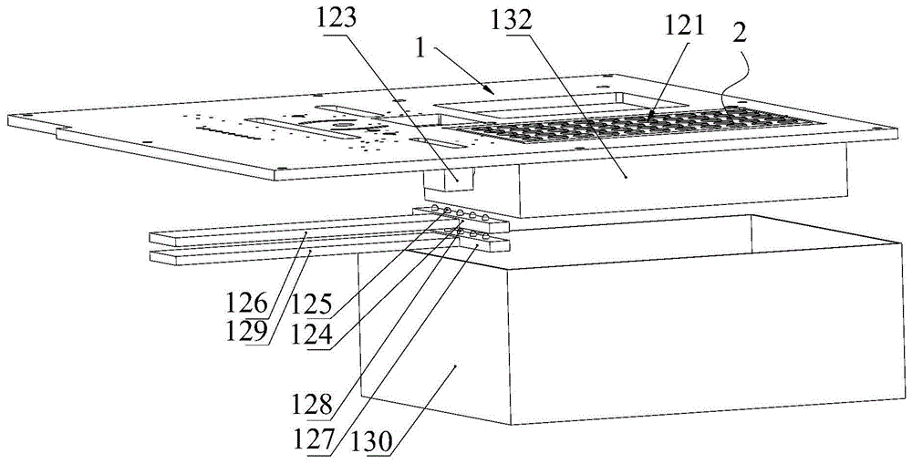
本实施例公开了一种试管清洗机构121,可以运用于实施例1、2、3或者4中,即本实施例的试管清洗机构121可以替换实施例1的存储架,如图28和29所示,本实施例的试管清洗机构121包括:This embodiment discloses a test
存储架,转动安装在机架1上,存储架的上端面具有多个固定槽122,存储架具有初始工作位和清洗工作位,清洗工作位相对于初始工作位旋转180°;The storage rack is rotatably installed on the
试管自夹紧套45,固定安装在固定槽122中;The test tube self-clamping
旋转驱动件123,用于驱动存储架转动;a
清洗架124,位于存储架的下方,清洗架124上安装有多个喷水头125;The
第一往复元件126,用于驱动清洗架124往复移动,使水喷向固定在试管自夹紧套45上的试管;The
风干架127,位于存储架的下方,风干架127上安装有多个吹风头128;an air-drying rack 127, located below the storage rack, and a plurality of blowing
第二往复元件129,用于驱动风干架127往复移动,使风喷向固定在试管自夹紧套45上的试管;The
废液盒130,位于存储架的下方,用于接收废水。The
本申请的试管清洗机构121能够对试管进行自动清洗,使用时,试管固定在试管自夹紧套45上,通过旋转驱动件123使存储架转动180°,从初始工作位切换至清洗工作位,此时试管的开口向下,然后第一往复元件126和喷水头125工作,水喷射在试管中,对试管进行清洗,废水落入废液盒130内,清洗完成后第二往复元件129和吹风头128工作,对试管进行干燥,干燥完成后存储架旋转复位。The test
如图28所示,于本实施例中,机架1上具有避让口131,存储架设置在避让口131处。As shown in FIG. 28 , in this embodiment, the
实际运用时,旋转驱动件123为旋转气缸或者电机。In actual use, the
如图29所示,试管清洗机构121还包括与机架1固定的环形或矩形的围挡132,存储架的下端位于围挡132内,清洗架124和分干架均位于围挡132的下方。设置围挡132能够防止水到处溅射。As shown in FIG. 29 , the test
实际运用时,第一往复元件126为气缸或电动推杆;第二往复元件129为气缸或电动推杆。In practice, the
本实施例所说的试管指的是去掉盖子的试管。The test tube mentioned in this embodiment refers to the test tube with the cover removed.
以上所述仅为本发明的优选实施例,并非因此即限制本发明的专利保护范围,凡是运用本发明说明书及附图内容所作的等效结构变换,直接或间接运用在其他相关的技术领域,均同理包括在本发明的保护范围内。The above descriptions are only preferred embodiments of the present invention, and are not intended to limit the scope of patent protection of the present invention. Any equivalent structural transformation made by using the contents of the description and accompanying drawings of the present invention can be directly or indirectly used in other related technical fields. All are similarly included in the protection scope of the present invention.
Claims (10)
Priority Applications (1)
| Application Number | Priority Date | Filing Date | Title |
|---|---|---|---|
| CN202010670218.3A CN111804690B (en) | 2020-07-13 | 2020-07-13 | Test tube cleaning mechanism of water quality detection equipment and water quality detection equipment |
Applications Claiming Priority (1)
| Application Number | Priority Date | Filing Date | Title |
|---|---|---|---|
| CN202010670218.3A CN111804690B (en) | 2020-07-13 | 2020-07-13 | Test tube cleaning mechanism of water quality detection equipment and water quality detection equipment |
Publications (2)
| Publication Number | Publication Date |
|---|---|
| CN111804690A true CN111804690A (en) | 2020-10-23 |
| CN111804690B CN111804690B (en) | 2022-08-02 |
Family
ID=72841820
Family Applications (1)
| Application Number | Title | Priority Date | Filing Date |
|---|---|---|---|
| CN202010670218.3A Active CN111804690B (en) | 2020-07-13 | 2020-07-13 | Test tube cleaning mechanism of water quality detection equipment and water quality detection equipment |
Country Status (1)
| Country | Link |
|---|---|
| CN (1) | CN111804690B (en) |
Cited By (3)
| Publication number | Priority date | Publication date | Assignee | Title |
|---|---|---|---|---|
| CN114798641A (en) * | 2022-04-21 | 2022-07-29 | 哈尔滨跃渊环保智能装备有限责任公司 | Cleaning device and water quality detection equipment |
| CN114858735A (en) * | 2022-04-21 | 2022-08-05 | 哈尔滨跃渊环保智能装备有限责任公司 | Water quality testing equipment |
| CN114965304A (en) * | 2022-08-02 | 2022-08-30 | 河北华清环境科技集团股份有限公司 | Automatic total phosphorus analytical equipment of quality of water |
Citations (20)
| Publication number | Priority date | Publication date | Assignee | Title |
|---|---|---|---|---|
| US5265456A (en) * | 1992-06-29 | 1993-11-30 | Grumman Aerospace Corporation | Method of cold working holes using a shape memory alloy tool |
| US6263887B1 (en) * | 2000-01-14 | 2001-07-24 | Dornoch Medical Systems, Inc. | Liquid waste disposal and canister flushing system and method |
| US20030087454A1 (en) * | 2001-10-26 | 2003-05-08 | Schultz Gary A | Method and device for chemical analysis |
| EP2824458A1 (en) * | 2013-07-08 | 2015-01-14 | Siemens Healthcare Diagnostics Products GmbH | Method and device for separating magnetically attractable elements |
| CN104280560A (en) * | 2013-07-08 | 2015-01-14 | 西门子医学诊断产品有限责任公司 | Apparatus for separating spherical or cylindrical objects |
| CN105082051A (en) * | 2015-08-31 | 2015-11-25 | 重庆开奇科技发展有限公司 | Flow rotary production device for blood sampling pipes |
| JP2016211886A (en) * | 2015-04-30 | 2016-12-15 | シスメックス株式会社 | Inspected substance detection method, sample analysis cartridge and sample analysis device |
| CN107127364A (en) * | 2017-06-02 | 2017-09-05 | 四川利丰航空科技有限公司 | A kind of clamping device of pipe |
| US20180059125A1 (en) * | 2016-08-31 | 2018-03-01 | C A Casyso Ag | Controlled Blood Delivery To Mixing Chamber Of A Blood Testing Cartridge |
| CN107831040A (en) * | 2017-10-30 | 2018-03-23 | 奉化市泰峰电气科技有限公司 | A kind of fluid sample sampler |
| CN108031690A (en) * | 2018-01-01 | 2018-05-15 | 杨雪锋 | A chemical test tube pre-cleaning device |
| US20190041414A1 (en) * | 2017-08-01 | 2019-02-07 | Euroimmun Medizinische Labordiagnostika Ag | Apparatus and method for cleaning pipetting needles |
| CN208493889U (en) * | 2018-05-25 | 2019-02-15 | 天津市合润科技有限责任公司 | Side-feeding type permanent-magnet direct-drive stirring equipment |
| CN109941615A (en) * | 2019-04-04 | 2019-06-28 | 河南医学高等专科学校 | Nephrosis detection kit storing unit |
| CN110271750A (en) * | 2019-07-24 | 2019-09-24 | 苏州天茹生物科技有限公司 | One kind being used for biologic medical sample case |
| CN209589831U (en) * | 2018-12-28 | 2019-11-05 | 哈尔滨跃渊环保智能装备有限责任公司 | A kind of intelligent measurement water quality test device |
| CN209894708U (en) * | 2019-03-29 | 2020-01-03 | 驻马店扬翔饲料有限公司(法人独资) | Rapid detection device for swine disease antibodies and antigens |
| CN210269224U (en) * | 2019-07-08 | 2020-04-07 | 宝清县食品检验检测所 | Solid food sampler |
| CN111282491A (en) * | 2020-03-02 | 2020-06-16 | 蒋婵婵 | Test tube oscillation equipment for medical examination |
| CN210875136U (en) * | 2019-04-08 | 2020-06-30 | 哈尔滨元亨生物药业有限公司 | Adjustable magnetic stirrer |
-
2020
- 2020-07-13 CN CN202010670218.3A patent/CN111804690B/en active Active
Patent Citations (20)
| Publication number | Priority date | Publication date | Assignee | Title |
|---|---|---|---|---|
| US5265456A (en) * | 1992-06-29 | 1993-11-30 | Grumman Aerospace Corporation | Method of cold working holes using a shape memory alloy tool |
| US6263887B1 (en) * | 2000-01-14 | 2001-07-24 | Dornoch Medical Systems, Inc. | Liquid waste disposal and canister flushing system and method |
| US20030087454A1 (en) * | 2001-10-26 | 2003-05-08 | Schultz Gary A | Method and device for chemical analysis |
| EP2824458A1 (en) * | 2013-07-08 | 2015-01-14 | Siemens Healthcare Diagnostics Products GmbH | Method and device for separating magnetically attractable elements |
| CN104280560A (en) * | 2013-07-08 | 2015-01-14 | 西门子医学诊断产品有限责任公司 | Apparatus for separating spherical or cylindrical objects |
| JP2016211886A (en) * | 2015-04-30 | 2016-12-15 | シスメックス株式会社 | Inspected substance detection method, sample analysis cartridge and sample analysis device |
| CN105082051A (en) * | 2015-08-31 | 2015-11-25 | 重庆开奇科技发展有限公司 | Flow rotary production device for blood sampling pipes |
| US20180059125A1 (en) * | 2016-08-31 | 2018-03-01 | C A Casyso Ag | Controlled Blood Delivery To Mixing Chamber Of A Blood Testing Cartridge |
| CN107127364A (en) * | 2017-06-02 | 2017-09-05 | 四川利丰航空科技有限公司 | A kind of clamping device of pipe |
| US20190041414A1 (en) * | 2017-08-01 | 2019-02-07 | Euroimmun Medizinische Labordiagnostika Ag | Apparatus and method for cleaning pipetting needles |
| CN107831040A (en) * | 2017-10-30 | 2018-03-23 | 奉化市泰峰电气科技有限公司 | A kind of fluid sample sampler |
| CN108031690A (en) * | 2018-01-01 | 2018-05-15 | 杨雪锋 | A chemical test tube pre-cleaning device |
| CN208493889U (en) * | 2018-05-25 | 2019-02-15 | 天津市合润科技有限责任公司 | Side-feeding type permanent-magnet direct-drive stirring equipment |
| CN209589831U (en) * | 2018-12-28 | 2019-11-05 | 哈尔滨跃渊环保智能装备有限责任公司 | A kind of intelligent measurement water quality test device |
| CN209894708U (en) * | 2019-03-29 | 2020-01-03 | 驻马店扬翔饲料有限公司(法人独资) | Rapid detection device for swine disease antibodies and antigens |
| CN109941615A (en) * | 2019-04-04 | 2019-06-28 | 河南医学高等专科学校 | Nephrosis detection kit storing unit |
| CN210875136U (en) * | 2019-04-08 | 2020-06-30 | 哈尔滨元亨生物药业有限公司 | Adjustable magnetic stirrer |
| CN210269224U (en) * | 2019-07-08 | 2020-04-07 | 宝清县食品检验检测所 | Solid food sampler |
| CN110271750A (en) * | 2019-07-24 | 2019-09-24 | 苏州天茹生物科技有限公司 | One kind being used for biologic medical sample case |
| CN111282491A (en) * | 2020-03-02 | 2020-06-16 | 蒋婵婵 | Test tube oscillation equipment for medical examination |
Non-Patent Citations (1)
| Title |
|---|
| 陈汉涛: "磁力驱动搅拌反应釜的应用探析", 《中国高新技术企业》 * |
Cited By (5)
| Publication number | Priority date | Publication date | Assignee | Title |
|---|---|---|---|---|
| CN114798641A (en) * | 2022-04-21 | 2022-07-29 | 哈尔滨跃渊环保智能装备有限责任公司 | Cleaning device and water quality detection equipment |
| CN114858735A (en) * | 2022-04-21 | 2022-08-05 | 哈尔滨跃渊环保智能装备有限责任公司 | Water quality testing equipment |
| CN114798641B (en) * | 2022-04-21 | 2023-08-18 | 哈尔滨跃渊环保智能装备有限责任公司 | Cleaning device and water quality detection equipment |
| CN114858735B (en) * | 2022-04-21 | 2025-04-29 | 哈尔滨跃渊环保智能装备有限责任公司 | Water quality testing equipment |
| CN114965304A (en) * | 2022-08-02 | 2022-08-30 | 河北华清环境科技集团股份有限公司 | Automatic total phosphorus analytical equipment of quality of water |
Also Published As
| Publication number | Publication date |
|---|---|
| CN111804690B (en) | 2022-08-02 |
Similar Documents
| Publication | Publication Date | Title |
|---|---|---|
| CN111650195B (en) | Water quality detection equipment | |
| US5897837A (en) | Dispensing device and Immunoassay apparatus using the same | |
| CN111804690A (en) | Test tube cleaning mechanism for water quality testing equipment and water quality testing equipment | |
| CN103339513B (en) | Automatic analysis system | |
| CN212982433U (en) | Switch cover mechanism and water quality detection equipment | |
| KR20090058510A (en) | Chemical preparation device | |
| CN220271345U (en) | Sample processing system | |
| CN114858735A (en) | Water quality testing equipment | |
| JP5495453B2 (en) | Bacteria testing device | |
| CN117839522B (en) | Distributed flow matching liquid system | |
| WO2024250533A1 (en) | Sample processing system | |
| CN111735979B (en) | Sample cup conveying mechanism of water quality detection device and water quality detection device | |
| JP2002340912A (en) | Dispensing device | |
| CN212568489U (en) | Remove and snatch mechanism and water quality testing equipment | |
| CN212976226U (en) | Cuvette wiper mechanism and water quality testing equipment | |
| CN111729595B (en) | Stirring mechanism of water quality detection equipment and water quality detection equipment | |
| CN217479058U (en) | A nuclear medicine sub-packaging equipment | |
| US6958234B2 (en) | Automatic microbial air sampling system and method | |
| CN111744864B (en) | Syringe wiper mechanism and water quality testing equipment of water quality testing equipment | |
| CN212568439U (en) | Snatch subassembly, remove and snatch mechanism and water quality testing equipment | |
| CN212568753U (en) | Waste liquid pouring mechanism and water quality detection equipment | |
| CN118560792B (en) | Fully automatic filling equipment for flexible packaging materials | |
| CN212974918U (en) | Shake even heating mechanism and water quality testing equipment | |
| CN212975177U (en) | Test tube subassembly and water quality testing equipment | |
| JP2002333450A (en) | Dispensing device |
Legal Events
| Date | Code | Title | Description |
|---|---|---|---|
| PB01 | Publication | ||
| PB01 | Publication | ||
| SE01 | Entry into force of request for substantive examination | ||
| SE01 | Entry into force of request for substantive examination | ||
| GR01 | Patent grant | ||
| GR01 | Patent grant |