CN111789699A - Independently controllable valve clamping system - Google Patents
Independently controllable valve clamping system Download PDFInfo
- Publication number
- CN111789699A CN111789699A CN201911138749.1A CN201911138749A CN111789699A CN 111789699 A CN111789699 A CN 111789699A CN 201911138749 A CN201911138749 A CN 201911138749A CN 111789699 A CN111789699 A CN 111789699A
- Authority
- CN
- China
- Prior art keywords
- valve
- clip
- proximal
- control
- wire
- Prior art date
- Legal status (The legal status is an assumption and is not a legal conclusion. Google has not performed a legal analysis and makes no representation as to the accuracy of the status listed.)
- Granted
Links
- 238000004804 winding Methods 0.000 claims description 20
- 229910001000 nickel titanium Inorganic materials 0.000 claims description 10
- 239000007769 metal material Substances 0.000 claims description 7
- 229910001220 stainless steel Inorganic materials 0.000 claims description 7
- 239000002861 polymer material Substances 0.000 claims description 6
- HZEWFHLRYVTOIW-UHFFFAOYSA-N [Ti].[Ni] Chemical group [Ti].[Ni] HZEWFHLRYVTOIW-UHFFFAOYSA-N 0.000 claims description 4
- 238000002788 crimping Methods 0.000 claims description 4
- 238000000465 moulding Methods 0.000 claims description 4
- 238000003466 welding Methods 0.000 claims description 4
- 239000000463 material Substances 0.000 claims description 3
- 229920000642 polymer Polymers 0.000 claims description 2
- 230000006386 memory function Effects 0.000 claims 1
- 230000006378 damage Effects 0.000 abstract description 10
- 238000005452 bending Methods 0.000 abstract description 8
- 230000009286 beneficial effect Effects 0.000 abstract description 8
- 210000004115 mitral valve Anatomy 0.000 description 40
- 238000010586 diagram Methods 0.000 description 13
- 210000005240 left ventricle Anatomy 0.000 description 13
- 210000005246 left atrium Anatomy 0.000 description 10
- 238000000034 method Methods 0.000 description 8
- 206010027727 Mitral valve incompetence Diseases 0.000 description 6
- 208000027418 Wounds and injury Diseases 0.000 description 6
- 239000008280 blood Substances 0.000 description 6
- 210000004369 blood Anatomy 0.000 description 6
- 230000008569 process Effects 0.000 description 5
- 239000010935 stainless steel Substances 0.000 description 5
- WAIPAZQMEIHHTJ-UHFFFAOYSA-N [Cr].[Co] Chemical class [Cr].[Co] WAIPAZQMEIHHTJ-UHFFFAOYSA-N 0.000 description 4
- 210000003698 chordae tendineae Anatomy 0.000 description 4
- 230000000694 effects Effects 0.000 description 3
- 230000006872 improvement Effects 0.000 description 3
- 208000014674 injury Diseases 0.000 description 3
- 208000005907 mitral valve insufficiency Diseases 0.000 description 3
- 230000002787 reinforcement Effects 0.000 description 3
- 238000007493 shaping process Methods 0.000 description 3
- 229910000531 Co alloy Inorganic materials 0.000 description 2
- 206010067171 Regurgitation Diseases 0.000 description 2
- 229910001069 Ti alloy Inorganic materials 0.000 description 2
- 230000009471 action Effects 0.000 description 2
- 230000003205 diastolic effect Effects 0.000 description 2
- 239000003814 drug Substances 0.000 description 2
- 229940079593 drug Drugs 0.000 description 2
- 238000004519 manufacturing process Methods 0.000 description 2
- 230000004048 modification Effects 0.000 description 2
- 238000012986 modification Methods 0.000 description 2
- 230000009467 reduction Effects 0.000 description 2
- 230000008439 repair process Effects 0.000 description 2
- 210000001519 tissue Anatomy 0.000 description 2
- 229910000838 Al alloy Inorganic materials 0.000 description 1
- 206010008745 Chordae tendinae rupture Diseases 0.000 description 1
- 239000004952 Polyamide Substances 0.000 description 1
- 239000004698 Polyethylene Substances 0.000 description 1
- 229910000831 Steel Inorganic materials 0.000 description 1
- 201000001943 Tricuspid Valve Insufficiency Diseases 0.000 description 1
- 230000004308 accommodation Effects 0.000 description 1
- 230000001746 atrial effect Effects 0.000 description 1
- 239000000560 biocompatible material Substances 0.000 description 1
- 229920000249 biocompatible polymer Polymers 0.000 description 1
- 230000017531 blood circulation Effects 0.000 description 1
- 230000008859 change Effects 0.000 description 1
- 230000007423 decrease Effects 0.000 description 1
- 239000013013 elastic material Substances 0.000 description 1
- 210000002889 endothelial cell Anatomy 0.000 description 1
- 238000009998 heat setting Methods 0.000 description 1
- 239000007943 implant Substances 0.000 description 1
- 238000002513 implantation Methods 0.000 description 1
- 230000002452 interceptive effect Effects 0.000 description 1
- 230000003902 lesion Effects 0.000 description 1
- 238000003754 machining Methods 0.000 description 1
- 230000007334 memory performance Effects 0.000 description 1
- 229910052751 metal Inorganic materials 0.000 description 1
- 239000002184 metal Substances 0.000 description 1
- HLXZNVUGXRDIFK-UHFFFAOYSA-N nickel titanium Chemical compound [Ti].[Ti].[Ti].[Ti].[Ti].[Ti].[Ti].[Ti].[Ti].[Ti].[Ti].[Ni].[Ni].[Ni].[Ni].[Ni].[Ni].[Ni].[Ni].[Ni].[Ni].[Ni].[Ni].[Ni].[Ni] HLXZNVUGXRDIFK-UHFFFAOYSA-N 0.000 description 1
- 210000003540 papillary muscle Anatomy 0.000 description 1
- 230000004796 pathophysiological change Effects 0.000 description 1
- 230000000149 penetrating effect Effects 0.000 description 1
- 229920002647 polyamide Polymers 0.000 description 1
- 229920000515 polycarbonate Polymers 0.000 description 1
- 239000004417 polycarbonate Substances 0.000 description 1
- 229920000728 polyester Polymers 0.000 description 1
- -1 polyethylene Polymers 0.000 description 1
- 229920000573 polyethylene Polymers 0.000 description 1
- 238000003825 pressing Methods 0.000 description 1
- 238000004080 punching Methods 0.000 description 1
- 239000012781 shape memory material Substances 0.000 description 1
- 229920002050 silicone resin Polymers 0.000 description 1
- 239000010959 steel Substances 0.000 description 1
- 238000010618 wire wrap Methods 0.000 description 1
Images


Classifications
-
- A—HUMAN NECESSITIES
- A61—MEDICAL OR VETERINARY SCIENCE; HYGIENE
- A61F—FILTERS IMPLANTABLE INTO BLOOD VESSELS; PROSTHESES; DEVICES PROVIDING PATENCY TO, OR PREVENTING COLLAPSING OF, TUBULAR STRUCTURES OF THE BODY, e.g. STENTS; ORTHOPAEDIC, NURSING OR CONTRACEPTIVE DEVICES; FOMENTATION; TREATMENT OR PROTECTION OF EYES OR EARS; BANDAGES, DRESSINGS OR ABSORBENT PADS; FIRST-AID KITS
- A61F2/00—Filters implantable into blood vessels; Prostheses, i.e. artificial substitutes or replacements for parts of the body; Appliances for connecting them with the body; Devices providing patency to, or preventing collapsing of, tubular structures of the body, e.g. stents
- A61F2/02—Prostheses implantable into the body
- A61F2/24—Heart valves ; Vascular valves, e.g. venous valves; Heart implants, e.g. passive devices for improving the function of the native valve or the heart muscle; Transmyocardial revascularisation [TMR] devices; Valves implantable in the body
- A61F2/2442—Annuloplasty rings or inserts for correcting the valve shape; Implants for improving the function of a native heart valve
Landscapes
- Health & Medical Sciences (AREA)
- Cardiology (AREA)
- Oral & Maxillofacial Surgery (AREA)
- Transplantation (AREA)
- Engineering & Computer Science (AREA)
- Biomedical Technology (AREA)
- Heart & Thoracic Surgery (AREA)
- Vascular Medicine (AREA)
- Life Sciences & Earth Sciences (AREA)
- Animal Behavior & Ethology (AREA)
- General Health & Medical Sciences (AREA)
- Public Health (AREA)
- Veterinary Medicine (AREA)
- Prostheses (AREA)
Abstract
本发明提供一种可独立控制的瓣膜夹合系统,包括瓣膜夹合器及用于输送瓣膜夹合器的输送装置。瓣膜夹合器包括固定座及可相对于固定座收拢或展开的近端夹片。输送装置包括输送鞘管及控制件,输送鞘管开设至少一对沿轴向延伸且关于其轴心线对称的第一孔腔,每一控制件活动地穿设于至少一对第一孔腔中,每一控制件对应连接一近端夹片以控制近端夹片相对于固定座收拢或展开。本发明中,朝近端拉紧控制件以控制对应的近端夹片相对于固定座收拢时,每一控制件作用于对应的近端夹片上的拉力的合力位于输送鞘管的轴心线上,从而避免输送鞘管弯曲及瓣膜夹合器发生摆动,有利于减少手术时间、提高手术效率,并避免对患者产生伤害。
The invention provides an independently controllable valve clamping system, comprising a valve clamping device and a delivery device for delivering the valve clamping device. The valve clamp includes a fixed base and a proximal clip that can be retracted or expanded relative to the fixed base. The delivery device includes a delivery sheath and a control member. The delivery sheath is provided with at least a pair of first cavities extending in the axial direction and symmetrical about its axis, and each control member is movably penetrated through at least a pair of the first cavities. Among them, each control element is correspondingly connected with a proximal clip to control the proximal clip to be folded or unfolded relative to the fixing base. In the present invention, when the control member is pulled toward the proximal end to control the corresponding proximal clip to be retracted relative to the fixed seat, the resultant force of the pulling force acting on the corresponding proximal clip by each control member is located on the axis of the delivery sheath. Therefore, the bending of the delivery sheath and the swinging of the valve clamp are avoided, which is beneficial to reduce the operation time, improve the operation efficiency, and avoid harm to the patient.
Description
技术领域technical field
本发明涉及医疗器械领域,尤其涉及一种可独立控制的瓣膜夹合系统。The invention relates to the field of medical devices, in particular to an independently controllable valve clamping system.
背景技术Background technique
请参阅图1,二尖瓣1是位于心脏左心房2与左心室3之间的单向阀,正常健康的二尖瓣1可以控制血液从左心房2流到左心室3,同时避免血液从左心室3流到左心房2。二尖瓣1包括一对瓣叶,称为前叶1a及后叶1b。前叶1a及后叶1b通过腱索4固定于左心室3的乳头肌上。正常情况下,心脏左心室3收缩时,前叶1a和后叶1b的边缘完全对合,避免血液从左心室3流到左心房2。请参阅图2,当二尖瓣1的瓣叶或其相关结构发生器质性改变或功能性改变时,如腱索4部分断裂,二尖瓣1的前叶1a和后叶1b对合不良,由此,当心脏左心室3收缩时,二尖瓣1不能完全关闭,导致血液从左心室3反流至左心房2,从而引起一系列的病理生理改变,称为“二尖瓣反流”。Please refer to Figure 1, the
现有一种微创治疗手术,其基于瓣膜的缘对缘手术原理,将瓣膜夹钳通过介入导管输送至二尖瓣处,再通过夹钳的相对开合同时夹持二尖瓣的前叶和后叶,从而将瓣叶拉近彼此,减轻“二尖瓣反流”。在夹持瓣叶过程中,由于二尖瓣的两个瓣叶始终处于大幅度、大力度的开合活动状态,夹持难度较大,通常希望能单独控制每侧瓣叶的夹持动作。There is a minimally invasive treatment operation, which is based on the principle of edge-to-edge operation of the valve, and the valve clamp is delivered to the mitral valve through an interventional catheter, and the anterior leaflet and the mitral valve are simultaneously clamped through the relative opening of the clamp. the posterior leaflets, thereby drawing the leaflets closer to each other, alleviating "mitral regurgitation". In the process of clamping the valve leaflets, since the two valve leaflets of the mitral valve are always in a state of large and powerful opening and closing activities, the clamping is difficult, and it is generally desirable to control the clamping action of each valve leaflet independently.
请参阅图3,现有一种瓣膜夹钳100',包括分别位于输送鞘管210'的轴心线相对的两侧的两组近端夹片20'和远端夹片30',每一近端夹片20'均通过对穿的控制线230'来控制运动,两个近端夹片20'可单独释放并在自身弹性作用下相对于固定座10'展开而向对应的远端夹片30'靠拢以分别夹持二尖瓣的两个瓣叶。然而,如图4所示,在现有技术中,控制每一近端夹片20'的控制线230'的进线与出线都是通过输送鞘管210'的轴心线一侧的同一个孔腔211'来实现,在重复手术操作的过程中,当单侧的近端夹片20'被控制线230'拉紧而相对于固定座10'收拢时,作用于该近端夹片20'上的拉力F'位于输送鞘管210'的轴心线一侧,拉力F'会对瓣膜夹钳100'产生一定的力矩,进而导致瓣膜夹钳100'朝拉力F'所在的一侧发生摆动,并进一步导致输送鞘管210'发生弯曲,使得操作者需要多次调整瓣膜夹钳100'的位置才能准确释放近端夹片20'以重新夹持二尖瓣的瓣叶,手术时间较长、效率较低;再者,瓣膜夹钳100'发生摆动还可能会牵拉瓣叶或缠挂腱索,进而撕裂瓣叶或挂断腱索,不仅会造成手术失败,甚至会对患者造成严重伤害。Please refer to FIG. 3 , there is a
发明内容SUMMARY OF THE INVENTION
有鉴于此,本发明提供一种可独立控制的瓣膜夹合系统,不仅能够单独夹持一侧的瓣叶,并能够避免输送鞘管的弯曲及瓣膜夹合器发生摆动,有利于减少手术时间、提高手术效率,并避免对患者产生伤害。In view of this, the present invention provides an independently controllable valve clamping system, which can not only clamp the valve leaflet on one side, but also avoid the bending of the delivery sheath and the swing of the valve clamp, which is beneficial to reduce the operation time. , Improve surgical efficiency and avoid harm to patients.
为解决上述技术问题,本发明提供一种可独立控制的瓣膜夹合系统,包括瓣膜夹合器及用于输送所述瓣膜夹合器的输送装置,所述瓣膜夹合器包括固定座及可相对于所述固定座收拢或展开的近端夹片,所述输送装置包括输送鞘管及控制件,每一所述控制件对应连接一所述近端夹片以控制所述近端夹片相对于所述固定座收拢或展开;其中,所述输送鞘管开设至少一对沿轴向延伸的第一孔腔,至少一对所述第一孔腔关于所述输送鞘管的轴心线对称,每一所述控制件活动地穿设于至少一对所述第一孔腔中。In order to solve the above-mentioned technical problems, the present invention provides an independently controllable valve clamping system, including a valve clamping device and a delivery device for delivering the valve clamping device, the valve clamping device comprising a fixing seat and a removable valve clamp. Relative to the proximal clip retracted or unfolded by the fixing base, the delivery device includes a delivery sheath and a control piece, each of the control pieces is correspondingly connected to one of the proximal clips to control the proximal clip retracted or unfolded relative to the fixed seat; wherein, the delivery sheath is provided with at least a pair of first bores extending in the axial direction, and at least a pair of the first bores are about the axis line of the delivery sheath Symmetrically, each of the control elements is movably penetrated in at least a pair of the first cavities.
本发明提供的可独立控制的瓣膜夹合系统,控制件穿设于输送鞘管关于其轴心线对称开设的至少一对第一孔腔中,当通过控制件控制对应的近端夹片相对于固定座收拢时,控制件作用于对应的近端夹片上的拉力的合力位于输送鞘管的轴心线上,从而避免输送鞘管弯曲及瓣膜夹合器发生摆动,有利于减少手术时间、提高手术效率,并避免对患者产生伤害。In the independently controllable valve clamping system provided by the present invention, the control member is penetrated into at least a pair of first cavities symmetrically opened about the axis of the delivery sheath. When the fixing seat is folded, the resultant force of the pulling force acting on the corresponding proximal clip by the control member is located on the axis of the delivery sheath, thereby avoiding the bending of the delivery sheath and the swing of the valve clamp, which is beneficial to reduce the operation time, Improve surgical efficiency and avoid harm to patients.
附图说明Description of drawings
为了更清楚地说明本发明实施例的技术方案,下面将对实施方式中所需要使用的附图作简单地介绍,显而易见地,下面描述中的附图是本发明一些实施方式,对于本领域普通技术人员来讲,在不付出创造性劳动的前提下,还可以根据这些附图获得其他的附图。In order to illustrate the technical solutions of the embodiments of the present invention more clearly, the following briefly introduces the accompanying drawings used in the implementation manner. As far as technical personnel are concerned, other drawings can also be obtained based on these drawings without any creative effort.
图1是二尖瓣正常状态时的示意图。Figure 1 is a schematic view of the mitral valve in a normal state.
图2是二尖瓣出现病变时的示意图。Fig. 2 is a schematic diagram of the mitral valve with lesions.
图3是现有技术中的瓣膜夹合器和输送鞘管的立体结构示意图。FIG. 3 is a schematic three-dimensional structural diagram of a valve clamp and a delivery sheath in the prior art.
图4是图3中的瓣膜夹合器单侧的近端夹片被拉紧时的示意图。FIG. 4 is a schematic view of the proximal clip on one side of the valve clip in FIG. 3 when it is tightened.
图5是本发明第一实施例提供的瓣膜夹合系统的立体结构示意图。FIG. 5 is a schematic three-dimensional structural diagram of the valve clamping system provided by the first embodiment of the present invention.
图6是图5中的瓣膜夹合器单侧的近端夹片被拉紧时的示意图。FIG. 6 is a schematic view of the proximal clip on one side of the valve clip in FIG. 5 when the clip is tightened.
图7是图5中的瓣膜夹合系统的部分结构的立体结构示意图。FIG. 7 is a three-dimensional schematic diagram of a partial structure of the valve clamping system in FIG. 5 .
图8是图7中的固定座的立体结构示意图。FIG. 8 is a schematic three-dimensional structural diagram of the fixing base in FIG. 7 .
图9是图7中的近端夹片的立体结构示意图。FIG. 9 is a schematic three-dimensional structural diagram of the proximal clip in FIG. 7 .
图10是图5中的瓣膜夹合器的使用状态示意图。FIG. 10 is a schematic view of the valve clamp in FIG. 5 in use.
图11是图10中的瓣膜夹合器夹持瓣叶后,心脏收缩时二尖瓣示意图。Fig. 11 is a schematic diagram of the mitral valve when the heart contracts after the valve clamp in Fig. 10 clamps the valve leaflets.
图12是图10中的瓣膜夹合器夹持瓣叶后,心脏舒张时二尖瓣示意图。Fig. 12 is a schematic diagram of the mitral valve during diastole after the valve clamp in Fig. 10 has clamped the valve leaflets.
图13图5中的输送鞘管的远端面示意图。FIG. 13 is a schematic view of the distal end of the delivery sheath of FIG. 5 .
图14和图15是其他实施方式中的输送鞘管的远端面示意图。14 and 15 are schematic views of the distal end of the delivery sheath in other embodiments.
图16是图5中的输送装置的部分立体结构示意图。FIG. 16 is a partial perspective structural diagram of the conveying device in FIG. 5 .
图17是图16中的输送装置的剖视图。FIG. 17 is a cross-sectional view of the delivery device of FIG. 16 .
图18至图21是图5中的瓣膜夹合系统的使用过程示意图。18 to 21 are schematic diagrams of the use process of the valve clamping system in FIG. 5 .
图22是本发明第二实施例提供的瓣膜夹合系统的部分结构的立体结构示意图。FIG. 22 is a schematic three-dimensional structural diagram of a partial structure of the valve clamping system provided by the second embodiment of the present invention.
图23是本发明第三实施例提供的瓣膜夹合系统的部分结构的立体结构示意图。23 is a schematic three-dimensional structural diagram of a partial structure of the valve clamping system provided by the third embodiment of the present invention.
图24是本发明第四实施例提供的瓣膜夹合系统的结构示意图。24 is a schematic structural diagram of a valve clamping system provided by a fourth embodiment of the present invention.
具体实施方式Detailed ways
下面将结合本发明实施例中的附图,对本发明实施例中的技术方案进行清楚、完整地描述,显然,所描述的实施例仅仅是本发明一部分实施例,而不是全部的实施例。基于本发明中的实施例,本领域普通技术人员在没有付出创造性劳动前提下所获得的所有其他实施例,都属于本发明保护的范围。The technical solutions in the embodiments of the present invention will be clearly and completely described below with reference to the accompanying drawings in the embodiments of the present invention. Obviously, the described embodiments are only a part of the embodiments of the present invention, but not all of the embodiments. Based on the embodiments of the present invention, all other embodiments obtained by those of ordinary skill in the art without creative efforts shall fall within the protection scope of the present invention.
在本发明的描述中,需要说明的是,术语“上”、“下”、“内”、“外”等指示的方位或位置关系为基于附图所示的方位或位置关系,仅是为了便于描述本发明和简化描述,而不是指示或暗示所指的装置或元件必须具有特定的方位、以特定的方位构造和操作,因此不能理解为对本发明的限制。此外,术语“第一”、“第二”、“第三”等仅用于描述目的,而不能理解为指示或暗示相对重要性。In the description of the present invention, it should be noted that the orientations or positional relationships indicated by the terms "upper", "lower", "inner", "outer", etc. are based on the orientations or positional relationships shown in the accompanying drawings, only for the purpose of It is convenient to describe the present invention and to simplify the description, rather than indicating or implying that the device or element referred to must have a particular orientation, be constructed and operate in a particular orientation, and therefore should not be construed as limiting the invention. Furthermore, the terms "first," "second," "third," etc. are used for descriptive purposes only and should not be construed to indicate or imply relative importance.
在本发明的描述中,需要说明的是,在介入医疗器械领域,近端是指距离操作者较近的一端,而远端是指距离操作者较远的一端;轴向是指平行于自然状态下的医疗器械远端中心和近端中心连线的方向。上述定义只是为了表述方便,并不能理解为对本发明的限制。In the description of the present invention, it should be noted that in the field of interventional medical devices, the proximal end refers to the end closer to the operator, while the distal end refers to the end farther away from the operator; the axial direction refers to the end parallel to the natural The direction of the line connecting the center of the distal end and the center of the proximal end of the medical device in the state. The above definitions are only for the convenience of expression, and should not be construed as limiting the present invention.
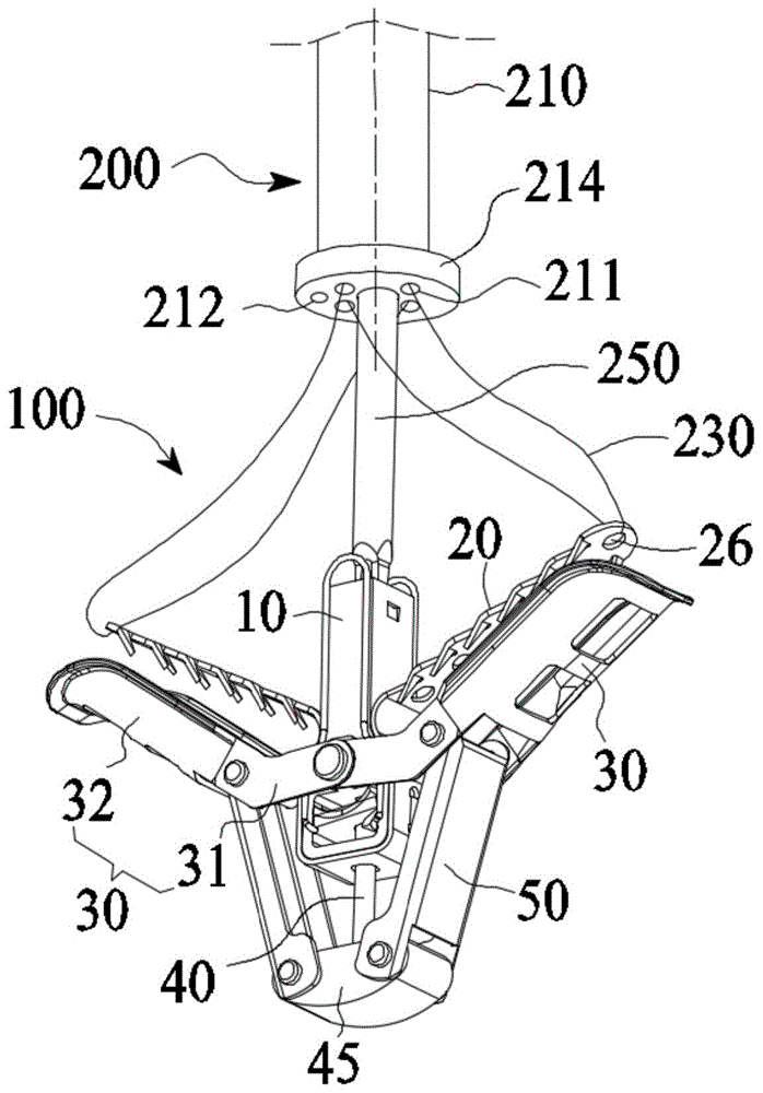
请一并参阅图5和图6,本发明的第一实施例提供一种可独立控制的瓣膜夹合系统,包括瓣膜夹合器100及用于输送瓣膜夹合器100的输送装置200。瓣膜夹合器100包括固定座10及可相对于固定座10收拢或展开的近端夹片20。输送装置200包括输送鞘管210及控制件230,每一控制件230对应连接一近端夹片20以控制近端夹片20相对于固定座10收拢或展开。具体的,输送鞘管210开设至少一对沿轴向延伸且关于输送鞘管210的轴心线对称的第一孔腔211,每一控制件230活动地穿设于至少一对第一孔腔211中,由此,当朝近端拉紧控制件230以控制对应的近端夹片20相对于固定座10收拢,每一控制件230作用于对应的近端夹片20上的拉力的合力F位于输送鞘管210的轴心线上,从而避免输送鞘管210弯曲及瓣膜夹合器100摆动。Please refer to FIG. 5 and FIG. 6 together. The first embodiment of the present invention provides an independently controllable valve clamping system, including a
其中,瓣膜夹合器100还包括转动连接于固定座10的远端夹片30及用于驱动远端夹片30相对于固定座10开合的驱动组件,驱动组件包括沿轴向滑动地设置于固定座10内的推杆40及连接远端夹片30与推杆40的连杆50。当推杆40相对于固定座10沿轴向滑动时,在连杆50的拉动下,远端夹片30相对于固定座10张开,将远端夹片30置于瓣膜下方的适当位置后,解除控制件230对近端夹片20的控制,近端夹片20被释放而相对于固定座10展开,近端夹片20向远端夹片30靠拢以夹持位于二者之间的瓣膜。当出现瓣膜夹持不牢靠的问题时,操作者可通过拉紧控制件230控制对应的近端夹片20相对于固定座10收拢,以便于能再次释放近端夹片20以重新夹持瓣膜。Wherein, the
本发明中,控制件230穿设于输送鞘管210关于其轴心线对称开设的至少一对第一孔腔211中,当通过控制件230控制对应的近端夹片20相对于固定座10收拢时,控制件230作用于对应的近端夹片20上的拉力的合力F位于输送鞘管210的轴心线上,使得该合力F对瓣膜夹合器100产生的力矩为零,从而避免输送鞘管210的弯曲及瓣膜夹合器100发生摆动,操作者不需要多次调整瓣膜夹合器100的位置即可快速准确地释放近端夹片20以夹持瓣膜,有利于减少手术时间、提高手术效率,并且能够避免瓣膜夹合器100摆动对患者产生的伤害。In the present invention, the
本实施例中,近端夹片20与远端夹片30的数量均为两个,两个近端夹片20与两个远端夹片30一一对应以构成两个夹钳,且两个夹钳关于固定座10轴对称设置。通过输送装置200将瓣膜夹合器100输送至患者的二尖瓣处,两个夹钳可分别夹持二尖瓣的前叶和后叶以减小瓣叶间隙,并作为植入物留在患者的体内,以减轻或治疗患者的“二尖瓣反流”。In this embodiment, the number of the
为保证植入后的安全性,固定座10、近端夹片20及远端夹片30分别由不锈钢、钴合金、钴铬合金、钛合金或镍钛合金等生物相容性金属材料制成;推杆40及连杆50分别由聚酯、硅树脂、不锈钢、钴合金、钴铬合金或钛合金等生物相容性高分子材料或金属材料制成。优选的,为了提高夹持力,本实施例中,固定座10、远端夹片30、推杆40及连杆50均由硬度较高的不锈钢或钴铬合金制成,近端夹片20由具有形状记忆功能的材料制成,优选超弹性的镍钛合金。In order to ensure the safety after implantation, the fixing
具体的,请一并参阅图7和图8,固定座10包括位于近端的第一座体11、位于远端的第二座体12,以及用于过渡连接第一座体11与第二座体12的第三座体13,三者可以是一体结构或非一体结构。本实施例中,三者为一体结构。Specifically, please refer to FIG. 7 and FIG. 8 together, the fixing
第一座体11沿轴向开设有贯通两端面的管腔,第一座体11的近端设置有连通管腔且关于第一座体11的轴心线对称的两个矩形卡孔111,用于与输送装置200的连接杆250连接。The
第二座体12沿垂直于轴向的方向开设有贯通第二座体12相对的两侧面的容置腔14,第二座体12于容置腔14的远端内壁沿轴向开设有通孔,该通孔的轴心线与第一座体11的管腔的轴心线共线。第二座体12相对的另外两侧面分别凸设有一矩形块121。The
第三座体13相对的两个平面分别凸设有一连接块131,连接块131开设有销钉孔,以用于安装转动销钉或螺栓。Two opposite planes of the
进一步的,第三座体13沿轴向开设有贯通孔(图中未示),第一座体11的管腔、第三座体13的贯通孔、第二座体12的容置腔14以及位于容置腔14的远端内壁的通孔同轴连通而构成一穿设通道15。Further, the
请一并参阅图5和图6,驱动组件包括推杆40,推杆40沿轴向滑动地穿设于固定座10的穿设通道内。推杆40的近端与输送装置200的芯轴(图中未示)连接。推杆40的远端设置连接座45,连接座45相对的两端开设有贯通的两个销钉孔。连接座45的形状为半球体、球冠或弹头形等任一结构,以使瓣膜夹合器100更容易在体内进行输送。Please refer to FIG. 5 and FIG. 6 together. The drive assembly includes a
需要说明的是,固定座10的容置腔内设置有锁紧件,固定座10相对的两侧面还分别设置有调节件,通过所述锁紧件与所述调节件的配合可以实现推杆40相对于固定座10固定或解锁,具体的,锁紧件可以是现有技术中的变形弹片及钢片的组合,调节件可以是镍钛合金等制成的金属丝,因与本发明的改进与创造无关,此处不做赘述。It should be noted that the accommodating cavity of the fixing
进一步的,如图5和图6所示,本实施例中,驱动组件还包括相对设置的两个连杆50,每一连杆50用于将对应一侧的远端夹片30连接于推杆40远端的连接座45,当推杆40在固定座10内沿轴向滑动时,可以通过连杆50拉动远端夹片30相对于固定座10开合。Further, as shown in FIG. 5 and FIG. 6 , in this embodiment, the driving assembly further includes two connecting
具体的,每一远端夹片30包括位于远端的连接段31以及连接于连接段31近端的夹持段32,连接段31远离对应的夹持段32的一端转动连接于固定座10的第三座体13的连接块131,连接段31靠近夹持段32的一端转动连接于相应一侧的连杆50的近端,该连杆50的远端通过转动销钉或螺栓转动连接于连接座45的销钉孔处。Specifically, each
本发明中,通过设置于固定座10的锁紧件及调节件的配合,使推杆40相对于固定座10解锁,推杆40可沿轴向朝远端滑动而相对于固定座10运动,由此,推杆40远端的连接座45相对于固定座10运动,连接座45带动连杆50运动,在连杆50的拉动下,远端夹片30可围绕连接块131上的销钉孔的中心转动而相对于固定座10张开,当近端夹片20被释放后,近端夹片20与远端夹片30之间形成瓣叶容纳空间,近端夹片20向对应的远端夹片30靠拢以夹持位于二者之间的瓣膜;在近端夹片20与远端夹片30夹紧瓣膜后,驱动推杆40沿轴向朝近端滑动,连杆50进而带动远端夹片30相对于固定座10闭合,直至远端夹片30相对于固定座10完全闭合,此时,瓣膜夹合器100处于收拢状态,再次通过锁紧件及调节件的配合,使推杆40相对于固定座10固定,以避免远端夹片30相对于固定座10张开,收拢状态的瓣膜夹合器100坠于瓣膜的下方。In the present invention, the
其中,连杆50带动远端夹片30相对于固定座10开合时,可以实现远端夹片30相对于固定座10在较大范围内开合,两个远端夹片30之间的夹角最大可达到300度,即,远端夹片30相对于固定座10打开后,可以实现一定程度的向下翻转,从而有利于夹持不断处于运动中的瓣膜,提高夹持成功率。本实施例中,两个远端夹片30之间的夹角范围优选为0-240度,更优为120-180度。Wherein, when the connecting
优选的,远端夹片30朝向近端夹片20的第一表面上可以设置夹持防滑结构(图中未示),以增强远端夹片30与瓣膜接触时的摩擦力,从而提供稳定的夹持力,并能够避免远端夹片30对瓣膜造成损伤。夹持防滑结构可以是设置于第一表面的凸起、凹槽或贴设于第一表面的由摩擦系数较高的生物相容性材料制成的垫片。Preferably, the first surface of the
其中,第一表面可以是平面,也可以是曲面。优选的,第一表面设置为曲面,以增加远端夹片30与瓣膜的接触面积及夹持面积,从而可以提供稳定的夹持力;再者,曲面的第一表面形成一收容槽,近端夹片20向远端夹片30靠拢时,近端夹片20至少部分收容于收容槽内,以压紧二者之间的瓣膜,并且能够尽量缩小瓣膜夹合器100收拢时的体积,利于在体内进行输送。Wherein, the first surface may be a plane or a curved surface. Preferably, the first surface is set as a curved surface to increase the contact area and the clamping area between the
进一步优选的,远端夹片30的第一表面上还可以施加活性药物,或开设至少一个开孔,以促进瓣膜组织在远端夹片30的内表面上的内皮细胞爬覆及生长;再者,开设开孔还可以减轻瓣膜夹合器100的整体重量,从而避免过重的瓣膜夹合器100长期坠在瓣叶下方产生滑脱或损伤瓣叶。Further preferably, active drugs can also be applied on the first surface of the
请一并参阅图5、图7和图9,每一近端夹片20包括相对设置的连接端21及自由端22,连接端21相对于固定座10固定。本实施例中,两个近端夹片20通过连接框23连接为一体,连接框23开设有供推杆40穿过的一通孔24,连接框23相对的两侧还分别开设有供第二座体12上的矩形块121穿过的一矩形孔25,连接框23套接于第二座体12及第三座体13的外侧,以将两个近端夹片20的连接端21相对固定于固定座10。在其他实施例中,近端夹片20的连接端21可以直接通过焊接、压接等连接方式固定于固定座10。Please refer to FIG. 5 , FIG. 7 and FIG. 9 together. Each
每一近端夹片20至少部分由具有形状记忆功能的材料制成。经过热定型处理后,在自然状态下,近端夹片20相对于固定座10向外辐射延伸,且优选朝近端延伸以便于和远端夹片30配合以夹持瓣叶。本实施例中,近端夹片20由镍钛合金切割后放置到定型模具中,再将定型模具于300-650℃条件下进行热处理,取出并迅速冷却,拆除定型模具得到定型好的近端夹片20。具体的,本实施例中,近端夹片20整体由超弹性的镍钛合金制成,连接框23也采用镍钛合金制成并与近端夹片20一体成型,以降低生产工艺难度,简化工艺流程,降低生产成本。在其他实施例中,连接框23也可以采用不锈钢制成,再与近端夹片20焊接,以提高连接框23与第二座体12的连接强度。Each
每一近端夹片20设置至少一连接结构26,以用于与控制件230连接。具体的,如图7所示,本实施例中,每一近端夹片20开设有一连接孔,该连接孔即为连接结构26,控制件230穿接于对应的近端夹片20的连接孔处并通过输送鞘管210延伸至患者体外,操作者通过体外部分的控制件230控制对应的近端夹片20相对于固定座10收拢或展开。优选的,本实施例中,连接结构26设置于近端夹片20相对于固定座10展开后远离固定座10的一端,即,自由端22,有利于操作者使用较小的拉力即可控制近端夹片20相对于固定座10收拢。Each
在其他实施例中,连接结构26可以是开设于近端夹片20上的两个或两个以上的连接孔,控制件230依次穿过多个连接孔以控制近端夹片20。In other embodiments, the connecting
在其他实施例中,连接结构26可以是凸设于近端夹片20朝向固定座10的表面上的至少一连接环,控制件230穿接于连接环上以控制近端夹片20。连接环与近端夹片20可以是一体结构或非一体结构。具体的,在一些实施例中,连接环通过机加工或冲压加工等加工方式与近端夹片20一体成型;在另一些实施例中,连接环可以是带有连接孔的零件并与近端夹片20通过压接、粘结或焊接等连接方式组合在一起。In other embodiments, the connecting
其中,当每一近端夹片20设置有至少两个连接结构26时,优选的,至少两个连接结构26的中心连线位于或靠近于近端夹片20的轴向中心线(即近端夹片20沿连接端21至自由端22方向的中心线),以避免控制件230作用于对应的近端夹片20上的拉力使近端夹片20绕其轴向中心线发生扭曲变形。Wherein, when each
进一步的,每一近端夹片20朝向远端夹片30的第二表面上设置有夹持增强件,以增加近端夹片20与瓣膜之间的摩擦力,提高瓣膜夹合器100对瓣膜的夹持力。具体的,本实施例中,夹持增强件为设置于第二表面相对的两侧的两列间隔设置的倒刺27。倒刺27可以采用一体成型方式在近端夹片20上形成,也可以采用与近端夹片20相同或不同的材料形成倒刺27再将其连接于近端夹片20的第二表面上。倒刺27的延伸方向与第二表面之间的夹角小于或等于90度,优选为30-60度,以增强瓣膜夹合器100对瓣膜的夹持力。Further, a clamping reinforcement is provided on the second surface of each
在其他实施例中,夹持增强件可以是凸设于第二表面的凸棱、凸台或其它不规则分布的凸起等结构,还可以是至少部分覆盖第二表面的粗糙表面或以上几种形式的组合,以提高对瓣膜的夹持力。In other embodiments, the clamping reinforcement may be a structure such as a rib, a boss, or other irregularly distributed protrusions protruding on the second surface, or a rough surface or a few above-mentioned structures that at least partially cover the second surface. A combination of forms to improve the holding force of the valve.
优选的,每一近端夹片20上还可以施加活性药物或开设至少一个开孔28。Preferably, active drug or at least one
需要说明的是,朝近端拉紧控制件230可以控制近端夹片20的自由端22相对于固定座10收拢,使得近端夹片20的自由端22贴合于固定座10的表面上以便于输送,而在解除控制件230对自由端22的控制后,近端夹片20的自由端22被释放,近端夹片20由于自身弹性记忆性能回弹并恢复自然状态,近端夹片20的自由端22相对于固定座10展开,以将瓣叶压向远端夹片30。优选的,自然展开状态下的两个近端夹片20之间的夹角应略大于两个远端夹片30之间的夹角,以提供更稳定的夹持力,即,近端夹片20与固定座10之间的夹角大于或等于与该侧对应的远端夹片30相对于固定座10完全张开时的远端夹片30与固定座10之间的夹角,从而保证近端夹片20与远端夹片30之间具有一定的夹紧力,以夹紧位于二者之间的瓣叶。本实施例中,近端夹片20的长度方向与固定座10的轴向之间的夹角的角度范围为0-150度,即,自然状态下,两个近端夹片20之间的夹角最大可达300度,两个近端夹片20之间的打开角度范围优选为0-240度,更优为160-200度。It should be noted that, pulling the
如前所述,本实施例提供的瓣膜夹合器100能够用于减轻或治疗“二尖瓣反流”。具体的,请一并参阅图10至图12,将瓣膜夹合器100置于二尖瓣的前叶1a及后叶1b的不能正常对合的位置,使得对应的一组近端夹片20及远端夹片30夹持二尖瓣的前叶1a边缘,另一组对应的近端夹片20及远端夹片30夹持二尖瓣的后叶1b边缘,以将二尖瓣的前叶1a及后叶1b不能正常对合的位置夹持在一起,图11和图12中所示箭头方向为血流方向。如图11所示,当心脏收缩时,前叶1a与后叶1b收拢,二尖瓣开口的面积A变小或二尖瓣能完全闭合,从而可减轻或治疗“二尖瓣反流”。如图12所示,当心脏舒张时,前叶1a及后叶1b仅在瓣膜夹合器100夹合的位置B对合在一起,前叶1a及后叶1b其它的位置仍然正常舒张,使得血液能够从左心房进入左心室,从而保证血液的正常流通。As mentioned above, the
可以理解的是,由于二尖瓣的两个瓣叶始终处于开合活动状态,夹持难度较大,往往只有一个瓣叶夹持成功,另外一个瓣叶则可能只被部分夹持,这可能导致二尖瓣的两个瓣叶夹合位置不理想或被部分夹持的瓣叶最终从瓣膜夹合器100中滑移,此时,只能重复进行手术操作,即,朝近端拉紧控制件230以控制压覆于只被部分夹持的瓣叶上的近端夹片20相对于固定座10收拢,调整瓣膜夹合器100的位置,使远端夹片30位于瓣叶的适当位置,然后解除控制件230对近端夹片20的控制,使近端夹片20相对于固定座10展开而靠拢远端夹片30以重新夹持瓣叶,直至二尖瓣的瓣叶被牢固夹持,反流消失或者达到最轻微状态。It is understandable that because the two leaflets of the mitral valve are always in an active state of opening and closing, it is difficult to clamp, and often only one leaflet is successfully clamped, and the other leaflet may only be partially clamped, which may As a result, the two leaflets of the mitral valve are in an unsatisfactory clamping position or the partially clamped leaflets eventually slip out of the
请参阅图5和图6,为了避免控制件230作用于对应的近端夹片20上的拉力导致输送鞘管210弯曲及瓣膜夹合器100发生摆动,本发明中,控制件230穿设于输送鞘管210关于其轴心线对称开设的至少一对第一孔腔211中而延伸至患者体外,当通过控制件230控制对应的近端夹片20相对于固定座10收拢时,每一控制件230作用于对应的近端夹片20上的拉力的合力F位于输送鞘管210的轴心线上,以使该合力F对瓣膜夹合器100产生的力矩为零,从而避免输送鞘管210弯曲及瓣膜夹合器100发生摆动,操作者不需要多次调整瓣膜夹合器100的位置即可快速准确地释放近端夹片20以重新夹持瓣膜,有利于减少手术时间、提高手术效率,并且能够避免瓣膜夹合器100摆动挂伤腱索或者组织对患者产生的伤害。Please refer to FIGS. 5 and 6 , in order to avoid the bending of the
如图5所示,本实施例中,输送鞘管210开设有两对第一孔腔211,每一对第一孔腔211中穿设有一控制件230以用于控制对应的一近端夹片20。也即是说,本实施例中,分别用于控制两个近端夹片20的两个控制件230穿设于不同的两对第一孔腔211中。As shown in FIG. 5 , in this embodiment, the
每一控制件230为单根控制线,所述控制线穿接于对应的近端夹片20后控制线的两末端分别穿设于一对第一孔腔211中并延伸至患者体外。具体的,控制线的进线通道为一对第一孔腔211中的其中一个第一孔腔211,出线通道为所述一对第一孔腔211中的另一个第一孔腔211,即,控制线的进线通道与出线通道关于输送鞘管210的轴心线对称。如图5所示,本实施例中,控制线沿进线通道到达对应的近端夹片20后穿过近端夹片20上的连接结构26,然后反向弯折再通过出线通道延伸至患者体外。如图6所示,操作者朝近端拉紧其中一根控制线以控制对应的一近端夹片20相对于固定座10收拢时,弯折成两部分的所述控制线作用于对应的近端夹片20上的拉力分别为F1和F2,拉力F1和拉力F2关于输送鞘管210的轴心线对称,其合力F位于输送鞘管210的轴心线上,使得合力F对瓣膜夹合器100产生的力矩为零,从而可以避免输送鞘管210弯曲及瓣膜夹合器100发生摆动,操作者可以快速调整瓣膜夹合器100的位置并准确释放近端夹片20以重新夹持瓣膜,有利于减少手术时间、提高手术效率,并且能够避免瓣膜夹合器100摆动对患者产生的伤害。Each
其中,控制线为单根丝线或者缠绕的多根丝线,所述丝线选自镍钛丝、不锈钢丝或高强度的高分子线。本实施例中,控制线采用单根镍钛丝,即,控制件230为单根镍钛丝。Wherein, the control wire is a single wire or a plurality of wound wires, and the wire is selected from nickel-titanium wire, stainless steel wire or high-strength polymer wire. In this embodiment, the control wire adopts a single nickel-titanium wire, that is, the
其中,第一孔腔211的形状可以是圆形、方形、多边形或其他异形形状。本实施例中,第一孔腔211为圆形孔腔。The shape of the
请参阅图13,本实施例中,两对第一孔腔211的轴心线至输送鞘管210的轴心线的距离相等,且每一第一孔腔211与另一对第一孔腔211的两个第一孔腔211的距离相等,即,两对第一孔腔211呈正方形分布。显然,在其他实施例中,每一第一孔腔211与另一对第一孔腔211的两个第一孔腔211的距离可以不相等,即,两对第一孔腔211呈长方形分布,如图14所示。Referring to FIG. 13 , in this embodiment, the distances from the axis lines of the two pairs of
在其他实施例中,两对第一孔腔211的轴心线至输送鞘管210的轴心线的距离可以不相等,即,两对第一孔腔211呈平行四边形分布,如图15所示。In other embodiments, the distances from the axis lines of the two pairs of
在其他实施例中,输送鞘管210可以只开设一对第一孔腔211,分别用于控制两个近端夹片20的两根控制线均穿设于所述一对第一孔腔211中,具体的,两个控制线的进线通道为所述一对第一孔腔211中的同一个第一孔腔211,两根控制线的出线通道为所述一对第一孔腔211中的另一个第一孔腔211。In other embodiments, the
进一步的,如图5和图13所示,本实施例中,瓣膜夹合系统还包括压力传感器(图中未示),输送鞘管210开设有沿轴向延伸的一第二孔腔212,压力传感器活动地穿设于第二孔腔212中,且可自第二孔腔212的远端伸出。当输送装置200将瓣膜夹合器100输送至心脏左心室并利用瓣膜夹合器100将二尖瓣的两个瓣叶夹合在一起后,可将压力传感器自第二孔腔212的远端伸入心脏的左心房,从而实时反馈心脏内的压力值,以确认患者的“二尖瓣反流”的减少情况,从而确定是否需要调整瓣膜夹合器100的位置并重新夹持二尖瓣的瓣叶以优化治疗效果。Further, as shown in FIG. 5 and FIG. 13 , in this embodiment, the valve clamping system further includes a pressure sensor (not shown in the drawings), and the
可以理解的是,压力传感器可以是在出厂时组装在输送鞘管210的第二孔腔212中,也可以采用其他兼容的商用压力传感器,由手术操作者在手术前组装在输送鞘管210的第二孔腔212中。It can be understood that the pressure sensor can be assembled in the
请一并参阅图5、图7、图16及图17,本实施例提供的瓣膜夹合系统包括瓣膜夹合器100及输送装置200,通过输送装置200将瓣膜夹合器100输送至二尖瓣处,并调整瓣膜夹合器100于二尖瓣的适宜位置。输送装置200包括操作手柄及输送组件,输送组件的近端与操作手柄连接,输送组件的远端与瓣膜夹合器100可拆卸连接。Please refer to FIG. 5 , FIG. 7 , FIG. 16 , and FIG. 17 together. The valve clamping system provided in this embodiment includes a
输送组件包括前述的输送鞘管210及穿设于输送鞘管210的第一孔腔211中的控制件230,进一步的,输送组件还包括插接于输送鞘管210远端的连接件250、活动地同轴套装于连接件250的管腔内的衬管270,以及活动地同轴套装于衬管270内的芯轴290。操作者通过置于患者体外的操作手柄能够拉紧控制件230,以及分别驱动衬管270、芯轴290进行相对移动或旋转。The delivery assembly includes the
输送鞘管210沿轴向开设有一第三孔腔213,连接件250插接于第三孔腔213的远端,衬管270、芯轴290穿过第三孔腔213而延伸至患者体外。优选的,本实施例中,输送鞘管210的远端设置有一固定件214,同轴套装在一起的连接件250、衬管270及芯轴290通过固定件214插接于输送鞘管210的第三孔腔213内,以提高连接强度。可以理解的是,固定件214开设有若干分别连通第一孔腔211、第二孔腔212及第三孔腔213的通孔。A
其中,输送鞘管210可以是生物相容性的金属材料或高分子材料通过一体成型制成的多腔管,也可以是生物相容性的金属材料或高分子材料制成的若干单根管体通过压接、熔接或粘结形成的多腔管。所述金属材料选自不锈钢、铝合金或钴铬合金;所述高分子材料选自聚碳酸酯、聚乙烯或聚酰胺。本实施例中,推送导管210为一体成型制成的多腔管,开设沿推送导管210的轴向延伸的若干孔腔,所述若干孔腔即形成前述的至少一对第一孔腔211、一第二孔腔212及一第三孔腔213。The
连接件250大致呈管状,连接件250的远端轴对称设置两个连接杆253,每一连接杆253的远端设置用于与固定座10可拆卸连接的卡扣255。轴对称设置的两个连接杆253彼此相对的内表面为与连接件250的管腔内圆柱面光滑过渡连接的弧面,且每一连接杆253的弧面至连接件250的轴心线的距离自近端向远端逐渐减小,即,每一连接杆253的远端朝连接件250的轴心线方向倾斜,两个连接杆253自近端向远端逐渐收拢靠近。The connecting
连接杆253由弹性材料制成,当连接杆253受到沿连接件250的径向向外的推力时,连接杆253的远端向外扩张。输送装置200的衬管270活动地穿设于连接件250的管腔内,驱动衬管270朝远端移动,衬管270沿径向向外抵推连接杆253,连接杆253的卡扣255向外扩张而卡入固定座10的卡孔111内,使得输送装置200通过连接件250与固定座10处于连接状态;可以理解,向近端回撤衬管270,连接杆253由于自身弹性回弹,连接杆253的远端朝连接件250的轴心线方向收拢,卡扣255退出对应的卡孔111,输送装置200与固定座10的连接状态即被解除。The connecting
芯轴290与推杆40可拆卸连接,以用于驱动推杆40沿固定座10的轴向滑动,从而带动远端夹片30相对于固定座10开合。本实施例中,芯轴290为远端开设有内螺纹孔(图中未标示)的圆杆体,内螺纹孔用于与推杆40近端的外螺纹进行螺纹连接。The
在其他实施例中,输送组件可以不包括衬管270,芯轴290的整体直径或芯轴290的远端部分直径较大,使得芯轴290的远端部分能直接抵推连接件250远端的卡扣255向外扩张,也即是说,芯轴290既可以用于抵推连接件250远端的卡扣255向外扩张,也可以用于驱动推杆40沿固定座10的轴向滑动。In other embodiments, the delivery assembly may not include the
需要说明的是,输送组件及瓣膜夹合器100可以采用现有的可调弯鞘管输送至患者体内。It should be noted that the delivery assembly and the
以下以二尖瓣的瓣膜修复过程为例,说明本发明的瓣膜夹合系统的操作方法,主要包括以下步骤:The following takes the valve repair process of the mitral valve as an example to illustrate the operation method of the valve clamping system of the present invention, which mainly includes the following steps:
第一步:将输送组件可拆卸连接于瓣膜夹合器100,具体的,利用衬管270将连接件250远端的卡扣255向外抵推,以使得卡扣255卡入到固定座10的卡孔111内,使固定座10与连接件250处于连接状态;旋转芯轴290,使芯轴290与推杆40螺接固定。朝近端拉紧控制件230以控制近端夹片20相对于固定座10收拢,使近端夹片20的自由端22贴合在固定座10的表面上。然后通过操作手柄朝远端移动芯轴290而带动推杆40沿轴向朝远端滑动,驱动远端夹片30相对于固定座10闭合,以使瓣膜夹合器100处于完全收拢状态,近端夹片20及远端夹片30均贴近于固定座10的表面,保持收拢状态不变。Step 1: Removably connect the delivery assembly to the
第二步:采用经房间隔的路径,通过可调弯鞘管将输送组件以及瓣膜夹合器100从左心房推进,经过二尖瓣到达左心室,如图18所示。Step 2: The delivery assembly and the
第三步:调整瓣膜夹合器100与二尖瓣的相对位置,使得瓣膜夹合器100接近二尖瓣的前叶1a和后叶1b。Step 3: Adjust the relative position of the
第四步:通过操作手柄朝近端移动芯轴290,从而带动推杆40朝近端滑动以驱动远端夹片30相对于固定座10张开,调整瓣膜夹合器100的方向,使得远端夹片30垂直于二尖瓣的对合线。Step 4: Move the
第五步:朝近端回撤整个瓣膜夹合器100,使远端夹片30在左心室一侧托住瓣叶,如图19所示。Step 5: withdraw the
第六步:解除每一控制件230对相应近端夹片20的控制,依次释放两侧的近端夹片20,每侧的近端夹片20在心房侧压住瓣叶并与该侧的远端夹片30配合以夹持瓣叶。在释放单侧近端夹片20的过程中,操作者在体外同时拉动需要收紧的近端夹片20对应的控制件230的进线端与出线端,作用于进线与出线的拉力大小相当,由于进线通道与出线通道处于输送鞘管210轴心线对称的两个第一孔腔211中,使得控制件230作用于对应的近端夹片20上的拉力的合力位于输送鞘管210的轴心线上,以避免输送鞘管210弯曲及瓣膜夹合器100摆动,从而实现独立控制每一近端夹片20相对于固定座10展开,二尖瓣的前叶1a和后叶1b分别被夹持在对应的近端夹片20及远端夹片30之间,实现瓣叶的完整夹持,如图20所示。Step 6: Release the control of each
第七步:将压力传感器自输送鞘管210的第二孔腔212的远端伸出进入到左心房,检测心脏内的压力值,以确认患者的“二尖瓣反流”的减少情况,从而确定是否需要调整瓣膜夹合器100的位置并重新夹持瓣叶以优化治疗效果。对于需要重新夹持瓣叶的情况,朝近端拉紧控制件230以控制压覆于夹持位置不理想的瓣叶上的近端夹片20相对于固定座10收拢,调整瓣膜夹合器100的位置,使远端夹片30位于瓣叶的适当位置,然后解除控制件230对近端夹片20的控制,使近端夹片20相对于固定座10展开而靠拢远端夹片30以重新夹持瓣叶,直至二尖瓣的瓣叶被完全夹持。Step 7: Extend the pressure sensor from the distal end of the
第八步:再次朝远端移动芯轴290,芯轴290带动推杆40朝远端轴向滑动,从而驱动远端夹片30相对于固定座10闭合,直至瓣膜夹合器100完全收拢,如图21所示。The eighth step: move the
第九步:通过操作手柄控制芯轴290旋转,使芯轴290与推杆40之间的螺纹连接解锁,再朝近端回撤衬管270和芯轴290,直至连接件250远端的卡扣255与固定座10的卡孔111解锁分离,瓣膜夹合器100与输送组件完全分离。最后,将输送组件撤出患者体外,此时,瓣膜夹合器100将二尖瓣的前叶1a和后叶1b拉向彼此,得到双孔化的二尖瓣,完成二尖瓣的缘对缘修复,瓣膜夹合器100留置于患者体内,如图10所示。The ninth step: control the rotation of the
可以理解的是,本发明的瓣膜夹合系统也可采用经心尖等路径输送瓣膜夹合器至二尖瓣处。It can be understood that, the valve clamping system of the present invention can also be used to deliver the valve clamp to the mitral valve through the apical and other routes.
请参阅图22,本发明第二实施例提供的瓣膜夹合系统的结构与第一实施例中的瓣膜夹合系统的结构相似,不同之处在于:在第二实施例中,每一控制件230b包括至少两根控制线,也即是说,每一近端夹片20通过至少两根控制线进行控制以实现相对于固定座10的收拢或展开。具体的,本实施例中,每一控制件230b包括两根控制线,两根控制线穿设于输送鞘管210的同一对第一孔腔211中,两根控制线的进线通道为所述一对第一孔腔211中的其中一个第一孔腔211,两根控制线的出线通道为所述一对第一孔腔211中的另一个第一孔腔211,每一根控制线的进线通道与出线通道仍关于输送鞘管210的轴心线对称,从而避免瓣膜夹合器100发生摆动。Referring to FIG. 22 , the structure of the valve clamping system provided by the second embodiment of the present invention is similar to the structure of the valve clamping system in the first embodiment, the difference is: in the second embodiment, each
可以理解的是,每一控制件230b包括至少两根控制线,能够提高每一控制件230b对相应的近端夹片20的控制力,即,至少两根控制线可以提供更大的拉力,使近端夹片20尽量紧贴固定座10,并防止近端夹片20因拉力不足而提前释放。It can be understood that, each
请参阅图23,本发明第三实施例提供的瓣膜夹合系统的结构与第一实施例中的瓣膜夹合系统的结构相似,不同之处在于:在第三实施例中,每一控制件230c包括至少一对控制线,也即是说,每一近端夹片20通过至少一对控制线进行控制以实现相对于固定座10的收拢或展开。至少一对控制线分别穿接于对应的近端夹片20后,每一对控制线穿设于输送鞘管210的一对第一孔腔211中并延伸至患者体外。Referring to FIG. 23 , the structure of the valve clamping system provided by the third embodiment of the present invention is similar to the structure of the valve clamping system in the first embodiment, the difference is: in the third embodiment, each
本实施例中,每一控制件230c包括一对控制线,一对控制线穿设于输送鞘管210的一对第一孔腔211中。具体的,用于控制每一近端夹片20的一对控制线中,其中一根控制线的进线通道与出线通道同为所述一对第一孔腔211中的其中一第一孔腔211,另一根控制线的进线通道与出线通道同为所述一对第一孔腔211中的另一第一孔腔211,即,用于控制每一近端夹片20的一对控制线关于输送鞘管210的轴心线对称设置,从而避免瓣膜夹合器100发生摆动。In this embodiment, each
在其他实施例中,每一控制件230c可以包括至少两对控制线,每一对控制线穿设于输送鞘管210的一对第一孔腔211中并延伸至患者体外。其中,用于控制每一近端夹片20的至少两对控制线中,不同的两对控制线可以通过相同的一对第一孔腔211穿出至患者体外,也可以分别通过一对第一孔腔211穿出至患者体外。In other embodiments, each
可以理解的是,每一控制件230c包括至少一对控制线,能够提高每一控制件230c对相应的近端夹片20的控制力,即,至少一对控制线可以提供更大的拉力,使近端夹片20尽量紧贴固定座10,并防止近端夹片20因拉力不足而提前释放。It can be understood that, each
请参阅图24,本发明第四实施例提供的瓣膜夹合系统的结构与第一实施例中的瓣膜夹合系统的结构相似,不同之处在于:在第四实施例中,连接件250或固定座10上设置有至少一绕线柱235,控制线(即控制件230)的进线端和/或出线端绕过至少一绕线柱235而延伸至患者体外。具体的,本实施例中,连接件250的外壁凸设有两个绕线柱235,两个绕线柱235关于连接件250的轴心线对称,控制线的进线端穿接于对应的近端夹片20后,其出线端绕过一绕线柱235而后向上延伸进入输送鞘管210的出线通道,直至延伸至患者体外。本实施例中,用于控制两个近端夹片20的两根控制线分别绕过不同的绕线柱235。Referring to FIG. 24 , the structure of the valve clamping system provided by the fourth embodiment of the present invention is similar to that of the valve clamping system in the first embodiment, except that in the fourth embodiment, the connecting
在其他实施例中,每一控制线的进线端可以绕过绕线柱235后再穿接于对应的近端夹片20,其出线端直接向上延伸进入输送鞘管210的出线通道,直至延伸至患者体外。In other embodiments, the incoming end of each control wire can bypass the winding
在其他实施例中,每一控制线的进线端和出线端都可以绕过绕线柱235而分别通过输送鞘管210的进线通道和出线通道延伸至患者体外。In other embodiments, the incoming wire end and the outgoing wire end of each control wire can bypass the winding
在其他实施例中,绕线柱235可以只设置有一个,用于控制不同的近端夹片20的两根控制线的进线端和/或出线端绕过同一个绕线柱235。In other embodiments, only one winding
优选的,绕线柱235上可以开设至少一绕线槽,控制线部分绕设于至少一绕线槽内。当控制线的进线端和出线端或者用于控制不同的近端夹片20的两根控制线的进线端和/或出线端同时绕设于绕线柱235上时,绕线柱235开设间隔的多个绕线槽,以避免控制线相互影响。Preferably, at least one winding slot may be formed on the winding
可以理解的是,控制线的进线端和/或出线端绕设于绕线柱235上,朝近端拉紧控制线以控制对应的近端夹片20相对于固定座10收拢时,控制线进线端和/或出线围绕绕线柱235滑动,绕线柱235起到定滑轮的作用,有利于操作者使用较小的拉力即可拉紧近端夹片20,避免近端夹片20提前释放。It can be understood that when the incoming end and/or the outgoing end of the control wire is wound on the winding
需要说明的是,以上内容均是以瓣膜夹合器用于减轻或治疗“二尖瓣反流”为例进行描述的。可以理解的是,在其他实施例中,瓣膜夹合器也可以用于减轻或治疗“三尖瓣反流”,其原理及结构与本发明实施例中用于解决“二尖瓣反流”的瓣膜夹合器的原理及结构大致相同,只需通过多组近端夹片和远端夹片构成多个夹钳,每个夹钳分别夹合一片瓣叶即可,此处不做赘述。It should be noted that, the above contents are all described by taking the valve clamp as an example for alleviating or treating "mitral valve regurgitation". It can be understood that, in other embodiments, the valve clamp can also be used to alleviate or treat "tricuspid valve regurgitation", and its principle and structure are the same as those used to solve "mitral valve regurgitation" in the embodiments of the present invention. The principle and structure of the valve clamp are basically the same, and it is only necessary to form multiple clamps by multiple sets of proximal clamps and distal clamps, and each clamp can clamp a valve leaflet, which will not be repeated here. .
显然,在其他实施例中,本发明提供的瓣膜夹合器还可以应用于需要将三个以上片状的瓣膜夹合在一起的其他微创外科手术中。Obviously, in other embodiments, the valve clamp provided by the present invention can also be applied to other minimally invasive surgical operations that need to clamp more than three sheet-shaped valves together.
以上是本发明实施例的实施方式,应当指出,对于本技术领域的普通技术人员来说,在不脱离本发明实施例原理的前提下,还可以做出若干改进和润饰,这些改进和润饰也视为本发明的保护范围。The above are the implementations of the embodiments of the present invention. It should be pointed out that for those of ordinary skill in the art, without departing from the principles of the embodiments of the present invention, several improvements and modifications can also be made. These improvements and modifications are also It is regarded as the protection scope of the present invention.
Claims (16)
Priority Applications (4)
| Application Number | Priority Date | Filing Date | Title |
|---|---|---|---|
| CN201911138749.1A CN111789699B (en) | 2019-11-19 | 2019-11-19 | Independently controlled valve clamping system |
| EP20890245.2A EP4062873A4 (en) | 2019-11-19 | 2020-09-23 | INDEPENDENTLY CONTROLLED VALVE TIGHTENING SYSTEM |
| PCT/CN2020/117249 WO2021098371A1 (en) | 2019-11-19 | 2020-09-23 | Independently controllable valve clamping system |
| US17/583,839 US20220142781A1 (en) | 2019-11-19 | 2022-01-25 | Valve clamping system capable of being independently controlled |
Applications Claiming Priority (1)
| Application Number | Priority Date | Filing Date | Title |
|---|---|---|---|
| CN201911138749.1A CN111789699B (en) | 2019-11-19 | 2019-11-19 | Independently controlled valve clamping system |
Publications (2)
| Publication Number | Publication Date |
|---|---|
| CN111789699A true CN111789699A (en) | 2020-10-20 |
| CN111789699B CN111789699B (en) | 2024-12-20 |
Family
ID=72805610
Family Applications (1)
| Application Number | Title | Priority Date | Filing Date |
|---|---|---|---|
| CN201911138749.1A Active CN111789699B (en) | 2019-11-19 | 2019-11-19 | Independently controlled valve clamping system |
Country Status (1)
| Country | Link |
|---|---|
| CN (1) | CN111789699B (en) |
Cited By (37)
| Publication number | Priority date | Publication date | Assignee | Title |
|---|---|---|---|---|
| CN112587284A (en) * | 2020-11-02 | 2021-04-02 | 上海竑宇医疗科技有限公司 | Heart apex implanted mitral valve clamping device and heart apex implanted mitral valve clamping method |
| CN112773563A (en) * | 2020-10-26 | 2021-05-11 | 上海汇禾医疗科技有限公司 | Separable conveying and clamping device |
| CN113017929A (en) * | 2021-04-02 | 2021-06-25 | 上海汇禾医疗科技有限公司 | Clamping apparatus |
| CN113208778A (en) * | 2021-05-08 | 2021-08-06 | 上海汇禾医疗科技有限公司 | Anchoring device |
| CN113288515A (en) * | 2021-05-25 | 2021-08-24 | 北京领健医疗科技有限公司 | Valve closing apparatus |
| CN113397764A (en) * | 2021-05-27 | 2021-09-17 | 华中科技大学同济医学院附属协和医院 | Heart valve fixture and conveying device |
| CN113440309A (en) * | 2020-10-26 | 2021-09-28 | 上海汇禾医疗科技有限公司 | Releasable assembly for securing a push rod |
| CN113499169A (en) * | 2021-08-02 | 2021-10-15 | 近江(天津)医疗科技有限公司 | Valve clamping device and valve clamping system |
| CN113749823A (en) * | 2021-10-12 | 2021-12-07 | 科凯(南通)生命科学有限公司 | Mitral valve repair clamp connected with conveying structure in clamping manner |
| CN113940791A (en) * | 2021-12-22 | 2022-01-18 | 科瑞迈吉(北京)医疗科技有限公司 | Mitral valve forceps holder and mitral valve forceps holder conveying device |
| CN113952012A (en) * | 2021-09-14 | 2022-01-21 | 漳州市第三医院(漳州市龙文医院) | Small trochanter bone block belt loop titanium plate and assembly thereof |
| CN114099075A (en) * | 2021-11-16 | 2022-03-01 | 上海傲流医疗科技有限公司 | A valve regurgitation repair fixture control structure |
| CN114099098A (en) * | 2021-11-16 | 2022-03-01 | 上海傲流医疗科技有限公司 | Valve backflow repair clamp recycling structure |
| CN114099074A (en) * | 2021-11-16 | 2022-03-01 | 上海傲流医疗科技有限公司 | A kind of valve regurgitation gathering and repairing fixture control structure |
| CN114159190A (en) * | 2021-12-01 | 2022-03-11 | 上海易桥医疗器械有限公司 | Control modules and conveying systems |
| CN114668457A (en) * | 2020-12-24 | 2022-06-28 | 杭州德晋医疗科技有限公司 | Valve cutting device |
| CN114681148A (en) * | 2020-12-31 | 2022-07-01 | 深圳市健心医疗科技有限公司 | Valve clamping system, delivery device and release assembly thereof |
| CN114681150A (en) * | 2020-12-31 | 2022-07-01 | 深圳市健心医疗科技有限公司 | Valve clamping system, delivery device and release assembly thereof |
| CN114681149A (en) * | 2020-12-31 | 2022-07-01 | 深圳市健心医疗科技有限公司 | Valve clamping system, delivery device and release assembly thereof |
| WO2022142259A1 (en) * | 2020-12-30 | 2022-07-07 | 沛嘉医疗科技(苏州)有限公司 | Tissue fixation device with self-locking function |
| CN114762636A (en) * | 2021-01-15 | 2022-07-19 | 杭州德晋医疗科技有限公司 | Self-adaptive valve clamping device and valve clamping system |
| CN114762635A (en) * | 2021-01-15 | 2022-07-19 | 杭州德晋医疗科技有限公司 | Valve clamping device and valve clamping system with full fitting |
| CN114788748A (en) * | 2022-05-10 | 2022-07-26 | 上海申淇医疗科技有限公司 | System for clamping tissue |
| CN114948339A (en) * | 2021-02-26 | 2022-08-30 | 杭州德晋医疗科技有限公司 | Convenient valve clip delivery device |
| CN115120387A (en) * | 2021-07-13 | 2022-09-30 | 瀚芯医疗科技(深圳)有限公司 | Valve clamping system |
| WO2022222855A1 (en) * | 2021-04-21 | 2022-10-27 | 上海申淇医疗科技有限公司 | Manipulatable valve clip system |
| CN115281894A (en) * | 2022-07-22 | 2022-11-04 | 北京领健医疗科技有限公司 | Valve clip control handle, delivery device and valve repair system |
| CN115317195A (en) * | 2021-05-11 | 2022-11-11 | 上海汇禾医疗科技有限公司 | Clamping instrument |
| CN115429492A (en) * | 2021-12-21 | 2022-12-06 | 瀚芯医疗科技(深圳)有限公司 | Valve clamping device and valve clamping system |
| CN115517817A (en) * | 2021-12-28 | 2022-12-27 | 瀚芯医疗科技(深圳)有限公司 | Valve clamping system |
| CN115517826A (en) * | 2022-09-30 | 2022-12-27 | 瀚芯医疗科技(深圳)有限公司 | Mitral valve clamping device and mitral valve clamping system |
| CN116172749A (en) * | 2021-11-27 | 2023-05-30 | 瀚芯医疗科技(深圳)有限公司 | Delivery Devices and Valve Clamping Systems |
| CN116172750A (en) * | 2021-11-27 | 2023-05-30 | 瀚芯医疗科技(深圳)有限公司 | Delivery Devices and Valve Clamping Systems |
| CN116350393A (en) * | 2021-12-28 | 2023-06-30 | 瀚芯医疗科技(深圳)有限公司 | Valve clamp and valve clamp system |
| WO2023124786A1 (en) * | 2021-12-28 | 2023-07-06 | 杭州德晋医疗科技有限公司 | Sealing member, sealing assembly, control assembly and valve clip delivery device |
| CN116983121A (en) * | 2023-09-05 | 2023-11-03 | 上海申淇医疗科技有限公司 | Valve clamping device and valve clamping system |
| WO2024067828A1 (en) | 2022-09-30 | 2024-04-04 | 应脉医疗科技(上海)有限公司 | Prosthesis system |
Citations (8)
| Publication number | Priority date | Publication date | Assignee | Title |
|---|---|---|---|---|
| US20130066341A1 (en) * | 2011-09-13 | 2013-03-14 | Abbott Cardiovascular Systems, Inc. | Independent gripper |
| US20150257883A1 (en) * | 2014-03-17 | 2015-09-17 | Evalve, Inc. | Mitral valve fixation device removal devices and methods |
| CN106175986A (en) * | 2016-07-26 | 2016-12-07 | 复旦大学附属中山医院 | A valve clamp |
| CN106491245A (en) * | 2015-09-06 | 2017-03-15 | 先健科技(深圳)有限公司 | Valve clamping device |
| US20180146966A1 (en) * | 2016-11-29 | 2018-05-31 | Evalve, Inc. | Tricuspid valve repair system |
| WO2019143726A1 (en) * | 2018-01-16 | 2019-07-25 | Medfree, Inc. | Tissue grasping devices and related methods |
| CN209548144U (en) * | 2018-05-17 | 2019-10-29 | 杭州德晋医疗科技有限公司 | Valve clamping machine and valve clamping system |
| CN211934427U (en) * | 2019-11-19 | 2020-11-17 | 杭州德晋医疗科技有限公司 | Independently controllable valve clamping system |
-
2019
- 2019-11-19 CN CN201911138749.1A patent/CN111789699B/en active Active
Patent Citations (8)
| Publication number | Priority date | Publication date | Assignee | Title |
|---|---|---|---|---|
| US20130066341A1 (en) * | 2011-09-13 | 2013-03-14 | Abbott Cardiovascular Systems, Inc. | Independent gripper |
| US20150257883A1 (en) * | 2014-03-17 | 2015-09-17 | Evalve, Inc. | Mitral valve fixation device removal devices and methods |
| CN106491245A (en) * | 2015-09-06 | 2017-03-15 | 先健科技(深圳)有限公司 | Valve clamping device |
| CN106175986A (en) * | 2016-07-26 | 2016-12-07 | 复旦大学附属中山医院 | A valve clamp |
| US20180146966A1 (en) * | 2016-11-29 | 2018-05-31 | Evalve, Inc. | Tricuspid valve repair system |
| WO2019143726A1 (en) * | 2018-01-16 | 2019-07-25 | Medfree, Inc. | Tissue grasping devices and related methods |
| CN209548144U (en) * | 2018-05-17 | 2019-10-29 | 杭州德晋医疗科技有限公司 | Valve clamping machine and valve clamping system |
| CN211934427U (en) * | 2019-11-19 | 2020-11-17 | 杭州德晋医疗科技有限公司 | Independently controllable valve clamping system |
Cited By (45)
| Publication number | Priority date | Publication date | Assignee | Title |
|---|---|---|---|---|
| CN112773563A (en) * | 2020-10-26 | 2021-05-11 | 上海汇禾医疗科技有限公司 | Separable conveying and clamping device |
| CN113440309A (en) * | 2020-10-26 | 2021-09-28 | 上海汇禾医疗科技有限公司 | Releasable assembly for securing a push rod |
| CN112587284A (en) * | 2020-11-02 | 2021-04-02 | 上海竑宇医疗科技有限公司 | Heart apex implanted mitral valve clamping device and heart apex implanted mitral valve clamping method |
| CN114668457A (en) * | 2020-12-24 | 2022-06-28 | 杭州德晋医疗科技有限公司 | Valve cutting device |
| WO2022142259A1 (en) * | 2020-12-30 | 2022-07-07 | 沛嘉医疗科技(苏州)有限公司 | Tissue fixation device with self-locking function |
| CN114681148B (en) * | 2020-12-31 | 2025-08-12 | 深圳市健心医疗科技有限公司 | Valve clip system, delivery device and release assembly therefor |
| CN114681149A (en) * | 2020-12-31 | 2022-07-01 | 深圳市健心医疗科技有限公司 | Valve clamping system, delivery device and release assembly thereof |
| CN114681150A (en) * | 2020-12-31 | 2022-07-01 | 深圳市健心医疗科技有限公司 | Valve clamping system, delivery device and release assembly thereof |
| CN114681148A (en) * | 2020-12-31 | 2022-07-01 | 深圳市健心医疗科技有限公司 | Valve clamping system, delivery device and release assembly thereof |
| CN114762635A (en) * | 2021-01-15 | 2022-07-19 | 杭州德晋医疗科技有限公司 | Valve clamping device and valve clamping system with full fitting |
| CN114762636A (en) * | 2021-01-15 | 2022-07-19 | 杭州德晋医疗科技有限公司 | Self-adaptive valve clamping device and valve clamping system |
| CN114948339A (en) * | 2021-02-26 | 2022-08-30 | 杭州德晋医疗科技有限公司 | Convenient valve clip delivery device |
| CN113017929A (en) * | 2021-04-02 | 2021-06-25 | 上海汇禾医疗科技有限公司 | Clamping apparatus |
| WO2022222855A1 (en) * | 2021-04-21 | 2022-10-27 | 上海申淇医疗科技有限公司 | Manipulatable valve clip system |
| CN113208778A (en) * | 2021-05-08 | 2021-08-06 | 上海汇禾医疗科技有限公司 | Anchoring device |
| CN115317195A (en) * | 2021-05-11 | 2022-11-11 | 上海汇禾医疗科技有限公司 | Clamping instrument |
| CN115317195B (en) * | 2021-05-11 | 2025-09-16 | 上海汇禾医疗科技有限公司 | Clamping apparatus |
| WO2022237037A1 (en) * | 2021-05-11 | 2022-11-17 | 上海汇禾医疗科技有限公司 | Clamping instrument |
| CN113288515A (en) * | 2021-05-25 | 2021-08-24 | 北京领健医疗科技有限公司 | Valve closing apparatus |
| CN113397764A (en) * | 2021-05-27 | 2021-09-17 | 华中科技大学同济医学院附属协和医院 | Heart valve fixture and conveying device |
| CN115120387A (en) * | 2021-07-13 | 2022-09-30 | 瀚芯医疗科技(深圳)有限公司 | Valve clamping system |
| CN113499169A (en) * | 2021-08-02 | 2021-10-15 | 近江(天津)医疗科技有限公司 | Valve clamping device and valve clamping system |
| CN113952012B (en) * | 2021-09-14 | 2024-04-26 | 漳州市第三医院(漳州市龙文医院) | A small trochanter bone block with loop titanium plate and its components |
| CN113952012A (en) * | 2021-09-14 | 2022-01-21 | 漳州市第三医院(漳州市龙文医院) | Small trochanter bone block belt loop titanium plate and assembly thereof |
| CN113749823A (en) * | 2021-10-12 | 2021-12-07 | 科凯(南通)生命科学有限公司 | Mitral valve repair clamp connected with conveying structure in clamping manner |
| CN113749823B (en) * | 2021-10-12 | 2023-06-27 | 科凯(南通)生命科学有限公司 | Mitral valve repair clamp connected with conveying structure in clamping mode |
| CN114099075B (en) * | 2021-11-16 | 2025-02-25 | 上海傲流医疗科技有限公司 | A valve regurgitation repair fixture control structure |
| CN114099074B (en) * | 2021-11-16 | 2025-02-25 | 上海傲流医疗科技有限公司 | A control structure for a valve regurgitation gathering repair fixture |
| CN114099075A (en) * | 2021-11-16 | 2022-03-01 | 上海傲流医疗科技有限公司 | A valve regurgitation repair fixture control structure |
| CN114099098A (en) * | 2021-11-16 | 2022-03-01 | 上海傲流医疗科技有限公司 | Valve backflow repair clamp recycling structure |
| CN114099074A (en) * | 2021-11-16 | 2022-03-01 | 上海傲流医疗科技有限公司 | A kind of valve regurgitation gathering and repairing fixture control structure |
| CN116172749A (en) * | 2021-11-27 | 2023-05-30 | 瀚芯医疗科技(深圳)有限公司 | Delivery Devices and Valve Clamping Systems |
| CN116172750A (en) * | 2021-11-27 | 2023-05-30 | 瀚芯医疗科技(深圳)有限公司 | Delivery Devices and Valve Clamping Systems |
| CN114159190A (en) * | 2021-12-01 | 2022-03-11 | 上海易桥医疗器械有限公司 | Control modules and conveying systems |
| CN115429492A (en) * | 2021-12-21 | 2022-12-06 | 瀚芯医疗科技(深圳)有限公司 | Valve clamping device and valve clamping system |
| CN113940791B (en) * | 2021-12-22 | 2023-02-28 | 科瑞迈吉(北京)医疗科技有限公司 | Mitral valve forceps holder and mitral valve forceps holder conveying device |
| CN113940791A (en) * | 2021-12-22 | 2022-01-18 | 科瑞迈吉(北京)医疗科技有限公司 | Mitral valve forceps holder and mitral valve forceps holder conveying device |
| CN115517817A (en) * | 2021-12-28 | 2022-12-27 | 瀚芯医疗科技(深圳)有限公司 | Valve clamping system |
| CN116350393A (en) * | 2021-12-28 | 2023-06-30 | 瀚芯医疗科技(深圳)有限公司 | Valve clamp and valve clamp system |
| WO2023124786A1 (en) * | 2021-12-28 | 2023-07-06 | 杭州德晋医疗科技有限公司 | Sealing member, sealing assembly, control assembly and valve clip delivery device |
| CN114788748A (en) * | 2022-05-10 | 2022-07-26 | 上海申淇医疗科技有限公司 | System for clamping tissue |
| CN115281894A (en) * | 2022-07-22 | 2022-11-04 | 北京领健医疗科技有限公司 | Valve clip control handle, delivery device and valve repair system |
| WO2024067828A1 (en) | 2022-09-30 | 2024-04-04 | 应脉医疗科技(上海)有限公司 | Prosthesis system |
| CN115517826A (en) * | 2022-09-30 | 2022-12-27 | 瀚芯医疗科技(深圳)有限公司 | Mitral valve clamping device and mitral valve clamping system |
| CN116983121A (en) * | 2023-09-05 | 2023-11-03 | 上海申淇医疗科技有限公司 | Valve clamping device and valve clamping system |
Also Published As
| Publication number | Publication date |
|---|---|
| CN111789699B (en) | 2024-12-20 |
Similar Documents
| Publication | Publication Date | Title |
|---|---|---|
| CN111789699A (en) | Independently controllable valve clamping system | |
| US20220142781A1 (en) | Valve clamping system capable of being independently controlled | |
| CN211934427U (en) | Independently controllable valve clamping system | |
| US20220192656A1 (en) | Device for heart repair | |
| CN111904660B (en) | Valve clamping device and valve clamping system | |
| JP6629956B2 (en) | Valve closure | |
| RU2759657C2 (en) | Apparatus for sealing a cardiac valve and apparatus for delivery thereof | |
| CN112386368B (en) | Adjustable valve clamp and valve clamping system | |
| WO2021027588A1 (en) | Adjustable valve clamping device and valve clamping system | |
| CN112206017B (en) | Easy-to-clamp valve clamp and valve clamping system | |
| EP2385809B1 (en) | Apparatus for minimally invasive heart valve procedures | |
| CN112741709A (en) | Adjustable valve clamping system | |
| CN110495972A (en) | Valve Clamping Device and Valve Clamping System | |
| WO2021008461A1 (en) | Easily operable valve clamping device and valve clamping system | |
| CN211834508U (en) | Valve clamping device easy to clamp and valve clamping system | |
| WO2023029724A1 (en) | Transcatheter annulus reduction system and application thereof | |
| CN114681143B (en) | An adaptive valve clamping device and valve clamping system | |
| CN114762636A (en) | Self-adaptive valve clamping device and valve clamping system | |
| CN212015867U (en) | Minimally invasive artificial chordae tendineae adjusting system | |
| CN211934428U (en) | Transcatheter anchor implantation device and transcatheter anchor implantation system | |
| WO2022241755A1 (en) | Ring contraction apparatus for mitral valve annulus | |
| US20250000653A1 (en) | Fixation device for implantation | |
| GB2579420A (en) | Device for heart repair | |
| CN216439372U (en) | An adaptive valve clamping device and valve clamping system | |
| CN212490255U (en) | Edge-to-edge repair device and edge-to-edge repair system |
Legal Events
| Date | Code | Title | Description |
|---|---|---|---|
| PB01 | Publication | ||
| PB01 | Publication | ||
| SE01 | Entry into force of request for substantive examination | ||
| SE01 | Entry into force of request for substantive examination | ||
| GR01 | Patent grant | ||
| GR01 | Patent grant |