CN111721814A - Humidity sensor based on resonant desorption - Google Patents
Humidity sensor based on resonant desorption Download PDFInfo
- Publication number
- CN111721814A CN111721814A CN201910225631.6A CN201910225631A CN111721814A CN 111721814 A CN111721814 A CN 111721814A CN 201910225631 A CN201910225631 A CN 201910225631A CN 111721814 A CN111721814 A CN 111721814A
- Authority
- CN
- China
- Prior art keywords
- humidity
- resonant
- electrode
- resonance
- humidity sensor
- Prior art date
- Legal status (The legal status is an assumption and is not a legal conclusion. Google has not performed a legal analysis and makes no representation as to the accuracy of the status listed.)
- Pending
Links
- 238000003795 desorption Methods 0.000 title claims abstract description 31
- 239000010410 layer Substances 0.000 claims abstract description 70
- 239000000758 substrate Substances 0.000 claims abstract description 32
- 239000002346 layers by function Substances 0.000 claims abstract description 22
- 238000007791 dehumidification Methods 0.000 claims abstract description 20
- 238000005259 measurement Methods 0.000 claims abstract description 13
- 230000010358 mechanical oscillation Effects 0.000 claims abstract description 7
- 239000000463 material Substances 0.000 claims description 23
- XLOMVQKBTHCTTD-UHFFFAOYSA-N zinc oxide Inorganic materials [Zn]=O XLOMVQKBTHCTTD-UHFFFAOYSA-N 0.000 claims description 15
- VYPSYNLAJGMNEJ-UHFFFAOYSA-N silicon dioxide Inorganic materials O=[Si]=O VYPSYNLAJGMNEJ-UHFFFAOYSA-N 0.000 claims description 10
- 238000013461 design Methods 0.000 claims description 7
- 229910052710 silicon Inorganic materials 0.000 claims description 7
- 239000010703 silicon Substances 0.000 claims description 7
- 239000010453 quartz Substances 0.000 claims description 6
- 239000004642 Polyimide Substances 0.000 claims description 5
- 229920001721 polyimide Polymers 0.000 claims description 5
- 229910052581 Si3N4 Inorganic materials 0.000 claims description 4
- 229920000642 polymer Polymers 0.000 claims description 4
- 239000004065 semiconductor Substances 0.000 claims description 4
- HQVNEWCFYHHQES-UHFFFAOYSA-N silicon nitride Chemical group N12[Si]34N5[Si]62N3[Si]51N64 HQVNEWCFYHHQES-UHFFFAOYSA-N 0.000 claims description 4
- 229910052814 silicon oxide Inorganic materials 0.000 claims description 4
- 229910052782 aluminium Inorganic materials 0.000 claims description 3
- JRPBQTZRNDNNOP-UHFFFAOYSA-N barium titanate Chemical compound [Ba+2].[Ba+2].[O-][Ti]([O-])([O-])[O-] JRPBQTZRNDNNOP-UHFFFAOYSA-N 0.000 claims description 3
- 229910002113 barium titanate Inorganic materials 0.000 claims description 3
- 229910052802 copper Inorganic materials 0.000 claims description 3
- PMHQVHHXPFUNSP-UHFFFAOYSA-M copper(1+);methylsulfanylmethane;bromide Chemical compound Br[Cu].CSC PMHQVHHXPFUNSP-UHFFFAOYSA-M 0.000 claims description 3
- 239000013078 crystal Substances 0.000 claims description 3
- 229910052737 gold Inorganic materials 0.000 claims description 3
- 229910052451 lead zirconate titanate Inorganic materials 0.000 claims description 3
- HFGPZNIAWCZYJU-UHFFFAOYSA-N lead zirconate titanate Chemical compound [O-2].[O-2].[O-2].[O-2].[O-2].[Ti+4].[Zr+4].[Pb+2] HFGPZNIAWCZYJU-UHFFFAOYSA-N 0.000 claims description 3
- 229920003229 poly(methyl methacrylate) Polymers 0.000 claims description 3
- 239000004926 polymethyl methacrylate Substances 0.000 claims description 3
- 229910052709 silver Inorganic materials 0.000 claims description 3
- 238000010897 surface acoustic wave method Methods 0.000 claims description 3
- 229910052697 platinum Inorganic materials 0.000 claims description 2
- 238000000034 method Methods 0.000 abstract description 14
- 238000010438 heat treatment Methods 0.000 abstract description 9
- 230000004044 response Effects 0.000 abstract description 8
- 238000011084 recovery Methods 0.000 abstract description 5
- XLYOFNOQVPJJNP-UHFFFAOYSA-N water Chemical compound O XLYOFNOQVPJJNP-UHFFFAOYSA-N 0.000 description 14
- 238000002360 preparation method Methods 0.000 description 10
- 230000008569 process Effects 0.000 description 10
- 230000035945 sensitivity Effects 0.000 description 10
- 238000001514 detection method Methods 0.000 description 8
- 239000011787 zinc oxide Substances 0.000 description 7
- XUIMIQQOPSSXEZ-UHFFFAOYSA-N Silicon Chemical compound [Si] XUIMIQQOPSSXEZ-UHFFFAOYSA-N 0.000 description 6
- 239000003990 capacitor Substances 0.000 description 6
- 238000000206 photolithography Methods 0.000 description 6
- 230000008859 change Effects 0.000 description 5
- XPDWGBQVDMORPB-UHFFFAOYSA-N Fluoroform Chemical compound FC(F)F XPDWGBQVDMORPB-UHFFFAOYSA-N 0.000 description 4
- 230000008901 benefit Effects 0.000 description 4
- 239000010409 thin film Substances 0.000 description 4
- 230000010355 oscillation Effects 0.000 description 3
- 229920002120 photoresistant polymer Polymers 0.000 description 3
- 238000001179 sorption measurement Methods 0.000 description 3
- 238000004544 sputter deposition Methods 0.000 description 3
- 230000009286 beneficial effect Effects 0.000 description 2
- 238000005229 chemical vapour deposition Methods 0.000 description 2
- 238000010586 diagram Methods 0.000 description 2
- 238000005516 engineering process Methods 0.000 description 2
- 238000004518 low pressure chemical vapour deposition Methods 0.000 description 2
- 238000004519 manufacturing process Methods 0.000 description 2
- 230000005622 photoelectricity Effects 0.000 description 2
- 238000000926 separation method Methods 0.000 description 2
- 229910018503 SF6 Inorganic materials 0.000 description 1
- 239000000919 ceramic Substances 0.000 description 1
- 238000004140 cleaning Methods 0.000 description 1
- 238000000708 deep reactive-ion etching Methods 0.000 description 1
- 230000018044 dehydration Effects 0.000 description 1
- 238000006297 dehydration reaction Methods 0.000 description 1
- 230000001934 delay Effects 0.000 description 1
- 238000009792 diffusion process Methods 0.000 description 1
- 238000009826 distribution Methods 0.000 description 1
- 239000010408 film Substances 0.000 description 1
- 239000003292 glue Substances 0.000 description 1
- 230000001939 inductive effect Effects 0.000 description 1
- 238000009413 insulation Methods 0.000 description 1
- 230000007774 longterm Effects 0.000 description 1
- 238000001755 magnetron sputter deposition Methods 0.000 description 1
- 238000012423 maintenance Methods 0.000 description 1
- 239000008204 material by function Substances 0.000 description 1
- 238000000691 measurement method Methods 0.000 description 1
- 229910052751 metal Inorganic materials 0.000 description 1
- 239000002184 metal Substances 0.000 description 1
- 239000007769 metal material Substances 0.000 description 1
- 229910044991 metal oxide Inorganic materials 0.000 description 1
- 150000004706 metal oxides Chemical class 0.000 description 1
- 230000004048 modification Effects 0.000 description 1
- 238000012986 modification Methods 0.000 description 1
- 238000012544 monitoring process Methods 0.000 description 1
- 230000005693 optoelectronics Effects 0.000 description 1
- 230000003071 parasitic effect Effects 0.000 description 1
- 230000002093 peripheral effect Effects 0.000 description 1
- 238000001020 plasma etching Methods 0.000 description 1
- 229920005575 poly(amic acid) Polymers 0.000 description 1
- 238000011160 research Methods 0.000 description 1
- 230000000630 rising effect Effects 0.000 description 1
- 238000003980 solgel method Methods 0.000 description 1
- 238000000992 sputter etching Methods 0.000 description 1
- 238000003860 storage Methods 0.000 description 1
- SFZCNBIFKDRMGX-UHFFFAOYSA-N sulfur hexafluoride Chemical compound FS(F)(F)(F)(F)F SFZCNBIFKDRMGX-UHFFFAOYSA-N 0.000 description 1
- 229960000909 sulfur hexafluoride Drugs 0.000 description 1
- 239000002352 surface water Substances 0.000 description 1
Images


Classifications
-
- G—PHYSICS
- G01—MEASURING; TESTING
- G01N—INVESTIGATING OR ANALYSING MATERIALS BY DETERMINING THEIR CHEMICAL OR PHYSICAL PROPERTIES
- G01N27/00—Investigating or analysing materials by the use of electric, electrochemical, or magnetic means
- G01N27/02—Investigating or analysing materials by the use of electric, electrochemical, or magnetic means by investigating impedance
- G01N27/22—Investigating or analysing materials by the use of electric, electrochemical, or magnetic means by investigating impedance by investigating capacitance
- G01N27/223—Investigating or analysing materials by the use of electric, electrochemical, or magnetic means by investigating impedance by investigating capacitance for determining moisture content, e.g. humidity
-
- G—PHYSICS
- G01—MEASURING; TESTING
- G01N—INVESTIGATING OR ANALYSING MATERIALS BY DETERMINING THEIR CHEMICAL OR PHYSICAL PROPERTIES
- G01N21/00—Investigating or analysing materials by the use of optical means, i.e. using sub-millimetre waves, infrared, visible or ultraviolet light
- G01N21/84—Systems specially adapted for particular applications
-
- G—PHYSICS
- G01—MEASURING; TESTING
- G01N—INVESTIGATING OR ANALYSING MATERIALS BY DETERMINING THEIR CHEMICAL OR PHYSICAL PROPERTIES
- G01N27/00—Investigating or analysing materials by the use of electric, electrochemical, or magnetic means
-
- G—PHYSICS
- G01—MEASURING; TESTING
- G01N—INVESTIGATING OR ANALYSING MATERIALS BY DETERMINING THEIR CHEMICAL OR PHYSICAL PROPERTIES
- G01N27/00—Investigating or analysing materials by the use of electric, electrochemical, or magnetic means
- G01N27/02—Investigating or analysing materials by the use of electric, electrochemical, or magnetic means by investigating impedance
- G01N27/04—Investigating or analysing materials by the use of electric, electrochemical, or magnetic means by investigating impedance by investigating resistance
- G01N27/048—Investigating or analysing materials by the use of electric, electrochemical, or magnetic means by investigating impedance by investigating resistance for determining moisture content of the material
-
- G—PHYSICS
- G01—MEASURING; TESTING
- G01N—INVESTIGATING OR ANALYSING MATERIALS BY DETERMINING THEIR CHEMICAL OR PHYSICAL PROPERTIES
- G01N27/00—Investigating or analysing materials by the use of electric, electrochemical, or magnetic means
- G01N27/02—Investigating or analysing materials by the use of electric, electrochemical, or magnetic means by investigating impedance
- G01N27/22—Investigating or analysing materials by the use of electric, electrochemical, or magnetic means by investigating impedance by investigating capacitance
- G01N27/227—Sensors changing capacitance upon adsorption or absorption of fluid components, e.g. electrolyte-insulator-semiconductor sensors, MOS capacitors
-
- G—PHYSICS
- G01—MEASURING; TESTING
- G01N—INVESTIGATING OR ANALYSING MATERIALS BY DETERMINING THEIR CHEMICAL OR PHYSICAL PROPERTIES
- G01N27/00—Investigating or analysing materials by the use of electric, electrochemical, or magnetic means
- G01N27/72—Investigating or analysing materials by the use of electric, electrochemical, or magnetic means by investigating magnetic variables
- G01N27/74—Investigating or analysing materials by the use of electric, electrochemical, or magnetic means by investigating magnetic variables of fluids
Landscapes
- Chemical & Material Sciences (AREA)
- Biochemistry (AREA)
- Analytical Chemistry (AREA)
- Pathology (AREA)
- Immunology (AREA)
- Physics & Mathematics (AREA)
- Health & Medical Sciences (AREA)
- Life Sciences & Earth Sciences (AREA)
- General Physics & Mathematics (AREA)
- General Health & Medical Sciences (AREA)
- Electrochemistry (AREA)
- Chemical Kinetics & Catalysis (AREA)
- Engineering & Computer Science (AREA)
- Power Engineering (AREA)
- Investigating Or Analyzing Materials By The Use Of Electric Means (AREA)
Abstract
本发明公开了一种基于谐振式脱附的湿度传感器,包括:带有空腔的衬底;衬底上附着带有同样空腔的绝缘层;第一谐振电极,覆盖于衬底和绝缘层的空腔上;压电功能层,覆盖于第一谐振电极和衬底绝缘层之上;第二谐振电极,附着于压电功能层上,结合第一谐振电极和压电功能层作为谐振模块,实现机械振荡脱湿,该第二谐振电极结合湿敏介质层和上电极作为测湿模块,实现感湿测量;湿敏介质层,垂直堆叠于谐振模块形成的谐振区域,实现感湿测量;以及上电极,垂直堆叠于谐振模块形成的谐振区域,实现感湿测量。本发明利用谐振式机械脱湿,与传统的加热脱湿方式相比,避免了受热不均匀和加热后恢复慢等问题,可以快速初始化并提高湿度响应速度。
The invention discloses a humidity sensor based on resonant desorption, comprising: a substrate with a cavity; an insulating layer with the same cavity attached to the substrate; a first resonant electrode, covering the substrate and the insulating layer The piezoelectric functional layer is covered on the first resonant electrode and the substrate insulating layer; the second resonant electrode is attached to the piezoelectric functional layer, and is combined with the first resonant electrode and the piezoelectric functional layer as a resonant module , to achieve mechanical oscillation and dehumidification, the second resonant electrode is combined with the humidity-sensitive dielectric layer and the upper electrode as a humidity-sensing module to realize humidity-sensing measurement; the humidity-sensitive dielectric layer is vertically stacked on the resonance area formed by the resonance module to realize humidity-sensing measurement; And the upper electrode is vertically stacked on the resonance area formed by the resonance module to realize humidity sensing measurement. Compared with the traditional heating and dehumidification method, the invention avoids the problems of uneven heating and slow recovery after heating, and can quickly initialize and improve the humidity response speed.
Description
技术领域technical field
本发明涉及一种MEMS湿度传感器及其制备方法,尤其涉及一种与CMOS工艺兼容的基于谐振式脱附的湿度传感器。The invention relates to a MEMS humidity sensor and a preparation method thereof, in particular to a humidity sensor based on resonance type desorption compatible with CMOS technology.
背景技术Background technique
湿度是表征大气中水蒸气含量的参数,一般用相对湿度(%RH)表示,其值代表空气中水蒸气的压力和相同温度下饱和水蒸气压力的比值。湿度与人类的日常生活、农作物的生长、粮食的存储、医疗设备的维护、精密电子元器件的制造以及航空航天的高空作业等密切相关,所以湿度的监测变的越来越重要。Humidity is a parameter that characterizes the water vapor content in the atmosphere, generally expressed as relative humidity (%RH), and its value represents the ratio of the water vapor pressure in the air to the saturated water vapor pressure at the same temperature. Humidity is closely related to human daily life, the growth of crops, the storage of food, the maintenance of medical equipment, the manufacture of precision electronic components, and the high-altitude operations in aerospace, so humidity monitoring is becoming more and more important.
湿度传感器用于湿度检测,其基于湿敏功能材料的湿敏特性能够与水分子发生物理吸附作用,将水分子吸附量转换为电信号来实现湿度测量。按照其转换电信号种类的不同,通常可分为电容式、电阻式、电感式、谐振式、光电式等。其中电容式湿度传感器由于其高灵敏、低功耗、结构简单等诸多优点而被广泛研究应用。Humidity sensor is used for humidity detection. Based on the humidity-sensitive properties of humidity-sensitive functional materials, it can physically adsorb water molecules, and convert the adsorption amount of water molecules into electrical signals to realize humidity measurement. According to the different types of converted electrical signals, it can usually be divided into capacitive, resistive, inductive, resonant, optoelectronic and so on. Among them, capacitive humidity sensor has been widely studied and applied due to its high sensitivity, low power consumption, simple structure and many other advantages.
灵敏度和湿滞是影响湿度传感器性能的两个重要指标。以电容传感器为例,灵敏度S指相对于环境湿度的变化,电容量的变化程度。湿滞定义为湿敏元件升湿和降湿时,在同一湿度下电容不一致的现象,其根本原因在于感湿材料在吸湿和脱湿过程中含水分子量的不同而导致。通常,对于同一种湿敏材料,其亲水性越强则灵敏度越高,然而在脱湿过程中水分子将难以脱附,从而极大的增加了湿滞特性,为湿度检测带来不可避免的延迟和误差。所以,同时具备高灵敏度和低湿滞的湿敏传感器一直是广大学者们的研究目标。Sensitivity and hysteresis are two important indicators that affect the performance of humidity sensors. Taking a capacitive sensor as an example, the sensitivity S refers to the degree of change in capacitance relative to the change in ambient humidity. Humidity hysteresis is defined as the phenomenon that the capacitance of the humidity sensor is inconsistent under the same humidity when the humidity is rising and falling. Generally, for the same humidity-sensitive material, the stronger the hydrophilicity, the higher the sensitivity. However, it is difficult for water molecules to desorb during the dehumidification process, which greatly increases the humidity hysteresis characteristics and brings inevitable humidity detection. delays and errors. Therefore, a humidity sensor with high sensitivity and low hysteresis has always been the research goal of many scholars.
中国专利CN 104634832 A设计了一种快速响应的CMOS相对湿度传感器,由衬底、氧化层、电容电极、湿度敏感介质组成,其特点在于腐蚀衬底及其上方的氧化层,形成空腔,使得电容电极之间的湿度敏感介质能够直接与上下两边空气接触,有利于湿敏材料上水分子与空气水分子扩散,具有响应速度快、灵敏度高、寄生电容小等优点。但是,仅仅依靠材料自身亲疏水性,很难满足高湿度下快速湿度响应的要求,并且结构稳定性差。Chinese patent CN 104634832 A designs a fast-response CMOS relative humidity sensor, which is composed of a substrate, an oxide layer, a capacitive electrode, and a humidity-sensitive medium, which is characterized by corroding the substrate and the oxide layer above it to form a cavity, making The humidity-sensitive medium between the capacitor electrodes can directly contact the air on the upper and lower sides, which is conducive to the diffusion of water molecules on the humidity-sensitive material and air water molecules, and has the advantages of fast response speed, high sensitivity, and small parasitic capacitance. However, only relying on the hydrophilicity and hydrophobicity of the material itself is difficult to meet the requirements of fast humidity response under high humidity, and the structural stability is poor.
中国专利CN 103698367 A公开了一种加热式湿度传感器,其由衬底、下电极、电容感湿介质层、上电极、加热电阻所组成,其特点是加热电路环绕于湿度敏感电容周围。两只加热式湿度传感器交替使用,一只加热除湿的过程中,另一只进行湿度测量,并在一个工作周期后进行互换。该方法利用热脱附原理进行水分子强制脱离,优点是湿度测量范围广能够达到0%-100%RH,并且可应用于50℃-90℃低温环境中。但其缺点是高成本、高功耗、加热不均匀、温度分布不易控制等缺陷。电容、电阻及电感等物理量测量受温度影响严重,高温加热不仅引入高功耗,而且还需等到恢复环境温度才能再次测量,为提高检测效率,只能提高成本采用多传感器交替式工作。Chinese patent CN 103698367 A discloses a heated humidity sensor, which is composed of a substrate, a lower electrode, a capacitive humidity-sensitive medium layer, an upper electrode, and a heating resistor, and is characterized in that the heating circuit surrounds the humidity-sensitive capacitor. Two heated humidity sensors are used alternately, one is used for humidity measurement during heating and dehumidification, and the other is exchanged after a working cycle. The method utilizes the principle of thermal desorption to force the desorption of water molecules. The advantage is that the humidity measurement range can reach 0%-100% RH, and it can be applied in a low temperature environment of 50°C-90°C. However, its disadvantages are high cost, high power consumption, uneven heating, and difficult to control temperature distribution. The measurement of physical quantities such as capacitance, resistance and inductance is seriously affected by temperature. High temperature heating not only introduces high power consumption, but also needs to wait until the ambient temperature is restored before measuring again. In order to improve the detection efficiency, the cost can only be increased by using multiple sensors to work alternately.
发明内容SUMMARY OF THE INVENTION
有鉴于此,为了得到高灵敏且低湿滞的湿度传感器,本发明提供一种与CMOS工艺兼容的基于谐振式脱附的湿度传感器,以至少部分解决上述问题。In view of this, in order to obtain a humidity sensor with high sensitivity and low hysteresis, the present invention provides a humidity sensor based on resonant desorption compatible with CMOS technology, so as to at least partially solve the above problems.
为了实现上述目的,本发明采用的技术方案是:提供一种基于谐振式脱附的湿度传感器,包括:In order to achieve the above purpose, the technical solution adopted in the present invention is to provide a humidity sensor based on resonance type desorption, including:
带有空腔的衬底;a substrate with a cavity;
进一步的,该衬底为体硅。Further, the substrate is bulk silicon.
绝缘层,附着于该衬底上,该绝缘层具有同样的上述空腔;an insulating layer attached to the substrate, the insulating layer having the same cavity described above;
进一步的,该绝缘层为氮化硅或氧化硅。Further, the insulating layer is silicon nitride or silicon oxide.
更进一步的,上述衬底和绝缘层的空腔设置于下述提到的谐振模块的谐振区域。Further, the cavity of the substrate and the insulating layer is disposed in the resonance region of the resonance module mentioned below.
第一谐振电极,覆盖于衬底和绝缘层的空腔上,实现机械振荡脱湿。The first resonant electrode is covered on the cavity of the substrate and the insulating layer to achieve mechanical oscillation dehumidification.
压电功能层,覆盖于第一谐振电极和衬底绝缘层之上;a piezoelectric functional layer, covering the first resonant electrode and the substrate insulating layer;
进一步的,该压电功能层材料为:ZnO、石英、氮化铝、锆钛酸铅、钛酸钡或压电聚合物。Further, the piezoelectric functional layer material is: ZnO, quartz, aluminum nitride, lead zirconate titanate, barium titanate or piezoelectric polymer.
第二谐振电极,附着于压电功能层上,结合第一谐振电极和压电功能层作为谐振模块,实现机械振荡脱湿;The second resonant electrode is attached to the piezoelectric functional layer, and is combined with the first resonant electrode and the piezoelectric functional layer as a resonant module to realize mechanical oscillation and dehumidification;
进一步的,该谐振模块为声波谐振器、石英晶体振荡器、半导体材料振荡器或声表面波谐振器。Further, the resonance module is an acoustic wave resonator, a quartz crystal oscillator, a semiconductor material oscillator or a surface acoustic wave resonator.
湿敏介质层,垂直堆叠于谐振模块形成的谐振区域;The humidity-sensitive dielectric layer is vertically stacked on the resonance region formed by the resonance module;
进一步的,该湿敏介质层完全覆盖于第二谐振电极和压电功能层表面;Further, the humidity-sensitive dielectric layer completely covers the surface of the second resonant electrode and the piezoelectric functional layer;
或该湿敏介质层仅覆盖于第二谐振电极表面;Or the humidity-sensitive dielectric layer only covers the surface of the second resonant electrode;
更进一步的,该湿敏介质层材料为:聚酰亚胺、聚甲基丙烯酸甲脂及其衍生物或多孔介质湿敏材料。Further, the material of the humidity-sensitive medium layer is: polyimide, polymethyl methacrylate and derivatives thereof or porous medium humidity-sensitive material.
以及上电极,附着于该湿敏介质层上,该上电极结合第二谐振电极及湿敏介质层作为测湿模块,实现感湿测量;and an upper electrode, which is attached to the humidity-sensitive medium layer, and the upper electrode is combined with the second resonant electrode and the humidity-sensitive medium layer as a humidity-measuring module to realize humidity-sensing measurement;
进一步的,该上电极表面开窗设计,开窗图形包括正方形或圆形;Further, the upper electrode surface has a window design, and the window pattern includes a square or a circle;
更进一步的,该上电极为:电容、电阻、电感、谐振或光电,由此形成电容式、电阻式、电感式、谐振式或光电式湿度传感器;Further, the upper electrode is: capacitance, resistance, inductance, resonance or photoelectricity, thereby forming a capacitance type, resistance type, inductance type, resonance type or photoelectricity humidity sensor;
另有,上述谐振区域的形状为第一谐振电极和第二谐振电极的交叠部分;In addition, the shape of the above-mentioned resonant region is the overlapping portion of the first resonant electrode and the second resonant electrode;
上述第一谐振电极、第二谐振电极和上电极均通过焊盘引出;The first resonant electrode, the second resonant electrode and the upper electrode are all drawn out through the pad;
上述第一谐振电极、第二谐振电极与上电极材料为:Pt、Cu、Au、Ag或Al。The materials of the first resonant electrode, the second resonant electrode and the upper electrode are: Pt, Cu, Au, Ag or Al.
由于机械脱湿与传统的热脱附在原理上有根本不同,所以本发明提出的基于谐振式脱附的湿度传感器存在下述有益效果:Since mechanical dehumidification is fundamentally different from traditional thermal desorption in principle, the humidity sensor based on resonance desorption proposed by the present invention has the following beneficial effects:
(1)本设计利用谐振式机械脱湿,避免了热脱附带来的受热不均匀、恢复室温时间长、温度场不可控等问题,可以提高湿度的响应和恢复时间;(1) This design uses resonant mechanical dehumidification to avoid problems such as uneven heating, long recovery time to room temperature, and uncontrollable temperature field associated with thermal dehydration, which can improve the response and recovery time of humidity;
(2)该谐振式脱附湿度传感器的脱湿环节与测湿环节可紧密衔接,无需两个传感器交替使用,这样可大程度降低成本,提高检测效率,只需对一个湿敏元件进行检测和标定;(2) The dehumidification link and the humidity measurement link of the resonant desorption humidity sensor can be closely connected, and there is no need to use two sensors alternately, which can greatly reduce the cost and improve the detection efficiency. Only one humidity sensor needs to be detected and tested. calibration;
(3)该谐振式脱附湿度传感器利用谐振式机械脱湿,属于主动脱附,拥有更宽的温度环境使用范围,根据湿度介质层的不同可应用于低、中、高湿度检测;(3) The resonant desorption humidity sensor utilizes resonant mechanical dehumidification, which belongs to active desorption and has a wider range of temperature environments. It can be applied to low, medium and high humidity detection according to the different humidity medium layers;
(4)谐振式机械脱附,产生机械振动,传感器表面有一定的自清洁能力,所以更适用于恶劣环境中;(4) Resonant mechanical desorption produces mechanical vibration, and the sensor surface has a certain self-cleaning ability, so it is more suitable for harsh environments;
(5)本设计通过上电极和PI内部开窗,加大空气接触面积,增加了湿度响应灵敏度,同时缩短了响应时间;(5) In this design, the upper electrode and the internal window of the PI are opened to increase the air contact area, increase the humidity response sensitivity, and shorten the response time;
(6)本设计与CMOS工艺兼容,并且制作工艺简单,可批量生产。(6) The design is compatible with the CMOS process, and the fabrication process is simple and can be mass-produced.
附图说明Description of drawings
图1是本发明实施例提供的谐振脱湿电容湿度传感器截面示意图;1 is a schematic cross-sectional view of a resonant dehumidification capacitive humidity sensor provided by an embodiment of the present invention;
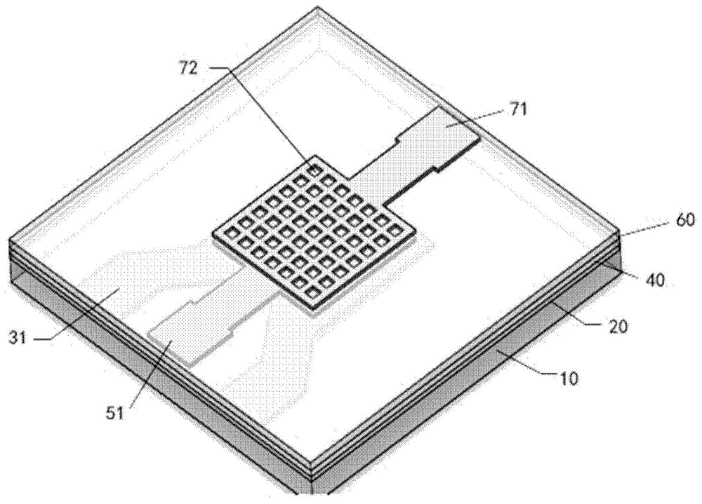
图2是图1实施例中谐振脱湿电容湿度传感器整体结构示意图;2 is a schematic diagram of the overall structure of the resonant dehumidification capacitive humidity sensor in the embodiment of FIG. 1;
图3是本发明实施例可替换结构的谐振脱湿电容湿度传感器截面示意图;3 is a schematic cross-sectional view of a resonant dehumidification capacitive humidity sensor with an alternative structure according to an embodiment of the present invention;
图4是图3可替换结构实施例的谐振脱湿电容湿度传感器整体示意图。FIG. 4 is an overall schematic diagram of the resonant dehumidification capacitive humidity sensor of the alternative structural embodiment of FIG. 3 .
图中:In the picture:
衬底10 硅衬底空腔11 绝缘层20 绝缘层空腔21
第一谐振电极30 第一谐振电极焊盘31 压电功能层40
第二谐振电极50 第二谐振电极焊盘51 湿敏介质层60
湿敏介质层窗口61 上电极70 电容电极焊盘71Moisture-sensitive
电容电极窗口72
具体实施方式Detailed ways
为使本发明的目的、技术方案和优点更加清楚明白,以下结合具体实施例,并参照附图,对本发明作进一步的详细说明。In order to make the objectives, technical solutions and advantages of the present invention more clearly understood, the present invention will be further described in detail below in conjunction with specific embodiments and with reference to the accompanying drawings.
本发明一实施例提供了一种基于谐振式脱附的湿度传感器,该湿度传感器由多层结构复合而成,为了方便理解,本实施例以电容湿度传感器为例做进一步说明,请参见图1-图4,首先对传感器结构做一详细介绍,包括:An embodiment of the present invention provides a humidity sensor based on resonant desorption. The humidity sensor is composed of a multi-layer structure. For the convenience of understanding, this embodiment takes a capacitive humidity sensor as an example for further description, please refer to FIG. 1 - Figure 4, first of all, a detailed introduction to the sensor structure, including:
带有空腔11的衬底10;
一些实施例中,该衬底10的材料可以为体硅。In some embodiments, the material of the
本实施例中,该衬底10使用体硅,且该衬底10作为湿度传感器整体结构的支撑骨架,以此完成该湿度传感器的后续制备。In this embodiment, bulk silicon is used as the
绝缘层20,附着于该衬底10上,该绝缘层20具有同样的上述空腔,作为电信号绝缘和谐振区域的支撑模块;The insulating
一些实施例中,该绝缘层20的材料可以为氮化硅或氧化硅。In some embodiments, the material of the insulating
第一谐振电极30,覆盖于衬底和绝缘层的空腔上,实现机械振荡脱湿。The first
压电功能层40,覆盖于第一谐振电极30和衬底绝缘层20之上,实现该第一谐振电极和一第二谐振电极50彼此绝缘;The piezoelectric
一些实施例中,该压电功能层40材料为ZnO,亦可采用其他压电材料如石英、氮化铝、锆钛酸铅、钛酸钡或者压电聚合物等。In some embodiments, the piezoelectric
第二谐振电极50,附着于压电功能层40上,结合第一谐振电极30和压电功能层40作为典型的薄膜体声波谐振模块,实现机械振荡脱湿;The second
一些实施例中,该第一谐振电极30与第二谐振电极50的交叠部分决定了谐振区域的形状;In some embodiments, the overlapping portion of the first
该薄膜体声波谐振模块也可以是其他形式的谐振器如石英晶体振荡器、半导体材料振荡器或声表面波谐振器。The thin film bulk acoustic wave resonator module can also be other forms of resonators such as quartz crystal oscillators, semiconductor material oscillators or surface acoustic wave resonators.
本实施例中,该谐振区域的形状对应上述衬底10和绝缘层20的空腔11和21。In this embodiment, the shape of the resonance region corresponds to the
湿敏介质层60,垂直堆叠于谐振模块形成的谐振区域;The humidity-
一些实施例中,该湿敏介质层60完全覆盖于第二谐振电极50和压电功能层40表面,如图1和图2所示;In some embodiments, the humidity-
或该湿敏介质层60仅覆盖于第二谐振电极50表面,如图3和图4所示。Or the humidity-
本实施例中,该湿敏介质层60厚度可选1-6um,本处选择2um;材料可为聚酰亚胺,亦可采用聚甲基丙烯酸甲脂类及其衍生物等聚合物或者多孔介质湿敏材料如多孔陶瓷基材料、多孔金属氧化物及其他多孔半导体材料等。该湿敏介质层60亦可采用开窗设计(如图3中61)。In this embodiment, the thickness of the humidity-
以及上电极70,附着于该湿敏介质层上,该上电极70结合第二谐振电极50及湿敏介质层60作为测湿模块,实现感湿测量;and the
一些实施例中,该上电极70表面开窗设计,开窗图形包括正方形或圆形,本实施例中选择10×10um的方窗(如图3中72),与上述湿敏介质层61窗口相契合;In some embodiments, the surface of the
本实施例中,该上电极为电容,基于此设计方案得到的可快速谐振脱湿电容湿度传感器仅仅是一种实施方案,同理可结合该谐振式脱湿手段,利用电阻、电感、谐振和光电等测量方式制作成可快速谐振脱湿的各种湿度传感器。In this embodiment, the upper electrode is a capacitor, and the capacitive humidity sensor that can quickly resonate and dehumidify based on this design scheme is only an implementation. Photoelectric and other measurement methods are made into various humidity sensors that can quickly resonate and dehumidify.
另外还包括,上述第一谐振电极30通过焊盘31引出;In addition, the above-mentioned first
上述第二谐振电极50附着于ZnO层之上,通过焊盘51引出;The above-mentioned second
上电极70通过焊盘71引出;The
本实施例中,上述第一谐振电极30、第二谐振电极50与上电极70等所有电极的材料均可采用金属Pt材料,亦可采用Cu、Au、Ag、Al等其它金属材料。In this embodiment, all electrodes such as the first
本发明提供的上述基于谐振式脱附的湿度传感器,其工作原理为:基于聚酰亚胺感湿功能层的湿敏电容传感器,当水分子吸附于聚酰亚胺表面时,由于不同湿度下水分子吸附浓度不同,导致电容传感器介质层介电常数的改变而发生电容变化。由于感湿介质层本身可具备多孔、多羟基等亲水基团而易于吸水,所以水分子吸附容易,脱附难。基于薄膜体声波谐振器(FBAR)的脱附模块,FBAR可通过外围振荡电路起振并维持等幅振荡,其振荡频率主要取决于谐振区域厚度,而振荡幅度主要取决于驱动电压强度,当驱动电压强度适当时,FBAR可大幅度谐振于本身基频附近,并将其机械能转化为表面水分子的动能及内能,使水分子能够快速机械脱附。The above-mentioned humidity sensor based on resonant desorption provided by the present invention works as follows: a humidity-sensitive capacitive sensor based on a polyimide moisture-sensing functional layer, when water molecules are adsorbed on the surface of polyimide, due to the water under different humidity Different molecular adsorption concentrations lead to the change of the dielectric constant of the capacitive sensor dielectric layer and the capacitance change. Since the moisture-sensing medium layer itself may have hydrophilic groups such as porous and polyhydroxyl groups, it is easy to absorb water, so the adsorption of water molecules is easy and the desorption is difficult. The desorption module based on Thin Film Bulk Acoustic Resonator (FBAR), the FBAR can oscillate through the peripheral oscillator circuit and maintain constant amplitude oscillation. Its oscillation frequency mainly depends on the thickness of the resonance region, and the oscillation amplitude mainly depends on the driving voltage strength. When the voltage intensity is appropriate, the FBAR can resonate in the vicinity of its fundamental frequency to a large extent, and convert its mechanical energy into the kinetic energy and internal energy of the surface water molecules, so that the water molecules can be mechanically desorbed quickly.
在实际应用中,该谐振脱湿电容湿度传感器的一个完整检测周期可分为脱湿恢复和湿度检测两环节,主要表现在第二谐振电极50需分时复用,在快速脱湿过程中作为谐振模块,切换至测湿过程时,则作为电容测湿模块,根据实际湿度环境的不同,可合理配置两环节时间占比和脱失功率。In practical applications, a complete detection cycle of the resonant dehumidification capacitive humidity sensor can be divided into two parts: dehumidification recovery and humidity detection. When the resonance module is switched to the humidity measurement process, it is used as a capacitive humidity measurement module. According to the actual humidity environment, the time ratio and loss power of the two links can be reasonably configured.
本发明另一实施例提供了一种上述基于谐振式脱附的湿度传感器的制备方法,下面同样结合图1-图4,对本发明制备方法作详细描述:Another embodiment of the present invention provides a preparation method of the above-mentioned resonant desorption-based humidity sensor. The preparation method of the present invention is also described in detail below with reference to FIGS. 1 to 4:
(1)薄膜体声波谐振器(1) Thin Film Bulk Acoustic Resonator
通过化学气相沉积(CVD)或者低压化学气相沉积(LPCVD)的方法在硅衬底10上制备300nm的氮化硅或氧化硅绝缘层20。A 300 nm silicon nitride or silicon
(2)FBAR下电极的制备(2) Preparation of FBAR lower electrode
通过光刻工艺及溅射工艺在硅上绝缘层20表面溅射200nm/30nm厚的Pt/Ti,通过Lift-off工艺形成FBAR下电极即第一谐振电极30的制备。The 200nm/30nm thick Pt/Ti is sputtered on the surface of the insulating
(3)FBAR压电功能层ZnO的制备(3) Preparation of FBAR piezoelectric functional layer ZnO
通过射频磁控溅射工艺在FBAR下电极即第一谐振电极30表面溅射一层2um厚的氧化锌,光刻形成固定图形的光刻胶掩膜层,通过稀硝酸湿法刻蚀的方式将ZnO层图形化,制备压电功能层40。A layer of zinc oxide with a thickness of 2 μm is sputtered on the surface of the lower electrode of the FBAR, that is, the first
(4)FBAR上电极的制备(4) Preparation of FBAR upper electrode
通过光刻工艺及溅射工艺在ZnO层表面溅射200nm/30nm厚的Pt/Ti,通过Lift-off工艺形成FBAR上电极即第二谐振电极50,此电极兼作为PI电容传感器的下电极。The 200nm/30nm thick Pt/Ti is sputtered on the surface of the ZnO layer by photolithography and sputtering, and the FBAR upper electrode ie the second
(5)PI层的制备(5) Preparation of PI layer
通过溶胶凝胶的方法将聚酰胺酸均匀涂于FBAR上电极即第二谐振电极50表面并通过软烘固定成膜,通过光刻形成固定图形的光刻胶掩膜层,利用等离子体刻蚀(ICP)的方式对介质层图形化,并最后通过300℃高温亚胺化,制备湿敏介质层60。The polyamic acid is uniformly coated on the surface of the upper electrode of the FBAR, that is, the second
(6)PI电容上电极的制备(6) Preparation of upper electrode of PI capacitor
通过光刻工艺及溅射工艺在PI层表面溅射200nm/30nm厚的Pt/Ti,通过Lift-off工艺形成PI电容上电极70。Pt/Ti with a thickness of 200 nm/30 nm is sputtered on the surface of the PI layer by a photolithography process and a sputtering process, and a PI capacitor
(7)Si衬底空腔释放及芯片分离(7) Si substrate cavity release and chip separation
通过光刻形成窗口及划片槽图形的厚胶掩膜层,通过ICP的方式,利用三氟甲烷干法刻蚀Si的背部绝缘层。通过深度离子刻蚀DRIE的方式,利用六氟化硫干法刻蚀Si衬底10,形成空腔11,最后通过ICP的方式,利用三氟甲烷干法刻蚀Si正面的绝缘层20,形成空腔21,该空腔11和21例如面积可选取为500×500um。。最终实现腔体的释放和芯片自分离。The thick glue mask layer of window and scribe groove pattern is formed by photolithography, and the back insulating layer of Si is etched by trifluoromethane dry method by means of ICP. By means of deep ion etching DRIE, the
至此,完成该谐振式脱附湿度传感器的制备。So far, the preparation of the resonant desorption humidity sensor is completed.
本发明提供的基于谐振式脱附的湿度传感器,不同于热脱附原理,既可保留湿敏材料本身高亲水高灵敏的特性,又无需大幅度改变传感器温度,延长恢复时间。相比于加热式湿度传感器,其拥有低功耗、长期稳定、灵敏度高、响应速度快、工作温度区间广且高湿度量程等特点。适用于复杂多变的高空气象环境中,有利于高频率湿度检测。The humidity sensor based on resonant desorption provided by the invention is different from the principle of thermal desorption, and can not only retain the high hydrophilicity and high sensitivity of the humidity sensitive material itself, but also does not need to greatly change the temperature of the sensor and prolong the recovery time. Compared with the heated humidity sensor, it has the characteristics of low power consumption, long-term stability, high sensitivity, fast response speed, wide operating temperature range and high humidity range. It is suitable for complex and changeable high-altitude meteorological environment, and is conducive to high-frequency humidity detection.
以上所述的具体实施例,对本发明的目的、技术方案和有益效果进行了进一步详细说明,应理解的是,以上所述仅为本发明的具体实施例而已,并不用于限制本发明,凡在本发明的精神和原则之内,所做的任何修改、等同替换、改进等,均应包含在本发明的保护范围之内。The specific embodiments described above further describe the purpose, technical solutions and beneficial effects of the present invention in detail. It should be understood that the above-mentioned specific embodiments are only specific embodiments of the present invention, and are not intended to limit the present invention. Within the spirit and principle of the present invention, any modifications, equivalent replacements, improvements, etc. made should be included within the protection scope of the present invention.
Claims (10)
Priority Applications (1)
| Application Number | Priority Date | Filing Date | Title |
|---|---|---|---|
| CN201910225631.6A CN111721814A (en) | 2019-03-22 | 2019-03-22 | Humidity sensor based on resonant desorption |
Applications Claiming Priority (1)
| Application Number | Priority Date | Filing Date | Title |
|---|---|---|---|
| CN201910225631.6A CN111721814A (en) | 2019-03-22 | 2019-03-22 | Humidity sensor based on resonant desorption |
Publications (1)
| Publication Number | Publication Date |
|---|---|
| CN111721814A true CN111721814A (en) | 2020-09-29 |
Family
ID=72564066
Family Applications (1)
| Application Number | Title | Priority Date | Filing Date |
|---|---|---|---|
| CN201910225631.6A Pending CN111721814A (en) | 2019-03-22 | 2019-03-22 | Humidity sensor based on resonant desorption |
Country Status (1)
| Country | Link |
|---|---|
| CN (1) | CN111721814A (en) |
Cited By (2)
| Publication number | Priority date | Publication date | Assignee | Title |
|---|---|---|---|---|
| CN115127594A (en) * | 2022-06-28 | 2022-09-30 | 电子科技大学 | Temperature and humidity sensor based on functional electrode layer and preparation method thereof |
| US12449389B2 (en) | 2023-02-23 | 2025-10-21 | Beijing Boe Technology Development Co., Ltd. | Humidity sensor, manufacturing method therefor and electronic device |
Citations (5)
| Publication number | Priority date | Publication date | Assignee | Title |
|---|---|---|---|---|
| CN1450719A (en) * | 2002-04-11 | 2003-10-22 | 三星电机株式会社 | Film bulk acoustic resonator and method of forming the same |
| CN104990968A (en) * | 2015-07-03 | 2015-10-21 | 中国科学院电子学研究所 | Humidity sensor device based on film volume acoustic wave resonator |
| CN105452853A (en) * | 2013-08-13 | 2016-03-30 | 株式会社村田制作所 | Temperature/humidity sensor |
| JP2016223885A (en) * | 2015-05-29 | 2016-12-28 | 株式会社デンソー | Humidity sensor |
| CN108896623A (en) * | 2018-07-11 | 2018-11-27 | 西南交通大学 | It is a kind of for measuring the numerical frequency formula humidity sensor of gas relative humidity |
-
2019
- 2019-03-22 CN CN201910225631.6A patent/CN111721814A/en active Pending
Patent Citations (5)
| Publication number | Priority date | Publication date | Assignee | Title |
|---|---|---|---|---|
| CN1450719A (en) * | 2002-04-11 | 2003-10-22 | 三星电机株式会社 | Film bulk acoustic resonator and method of forming the same |
| CN105452853A (en) * | 2013-08-13 | 2016-03-30 | 株式会社村田制作所 | Temperature/humidity sensor |
| JP2016223885A (en) * | 2015-05-29 | 2016-12-28 | 株式会社デンソー | Humidity sensor |
| CN104990968A (en) * | 2015-07-03 | 2015-10-21 | 中国科学院电子学研究所 | Humidity sensor device based on film volume acoustic wave resonator |
| CN108896623A (en) * | 2018-07-11 | 2018-11-27 | 西南交通大学 | It is a kind of for measuring the numerical frequency formula humidity sensor of gas relative humidity |
Non-Patent Citations (2)
| Title |
|---|
| 曾欢欢 等: "聚酞亚胺电容式湿度传感器的研制及改进", 《中国机械工程》 * |
| 轩伟鹏: "声波谐振器及其传感器应用研究", 《中国博士学位论文全文数据库 信息科技辑》 * |
Cited By (2)
| Publication number | Priority date | Publication date | Assignee | Title |
|---|---|---|---|---|
| CN115127594A (en) * | 2022-06-28 | 2022-09-30 | 电子科技大学 | Temperature and humidity sensor based on functional electrode layer and preparation method thereof |
| US12449389B2 (en) | 2023-02-23 | 2025-10-21 | Beijing Boe Technology Development Co., Ltd. | Humidity sensor, manufacturing method therefor and electronic device |
Similar Documents
| Publication | Publication Date | Title |
|---|---|---|
| CN104990968B (en) | Moisture sensor device based on FBAR | |
| CN107290241B (en) | A kind of QCM humidity sensor and preparation method thereof | |
| CN109556768B (en) | Pressure sensor and preparation method thereof | |
| CN104390720B (en) | A kind of capacitive temperature sensor based on graphene oxide and preparation method thereof | |
| CN108896623B (en) | A digital frequency humidity sensor for measuring gas relative humidity | |
| CN101532975A (en) | Constant temperature measurement-type micro humidity sensor and producing method thereof | |
| CN112034019B (en) | Passive wireless humidity sensor based on cantilever beam structure | |
| CN102944325A (en) | Passive wireless temperature and humidity integrated sensor | |
| TWI405710B (en) | Thermal bubble angle accelerometer using radio frequency identification tag technology | |
| CN112816109B (en) | RF pressure sensor | |
| CN110108381A (en) | LC passive wireless sensor that is a kind of while detecting temperature, humidity | |
| CN103675042B (en) | CMOS MEMS capacitive humidity sensor | |
| CN102297895A (en) | Nanometer polyaniline composite surface acoustic wave humidity sensor and production method thereof | |
| CN108918673A (en) | A kind of Surface Acoustic Waves Humidity Sensor with micro- heating function | |
| CN111721814A (en) | Humidity sensor based on resonant desorption | |
| CN207133226U (en) | A kind of QCM humidity sensors of high stability low humidity detection | |
| CN107290392B (en) | A QCM humidity sensor with high stability and low humidity detection and its preparation method | |
| CN209605973U (en) | A LC type temperature and humidity sensor | |
| CN209678515U (en) | Respiration detection sensor based on piezoelectric cantilever beam | |
| CN1210565C (en) | Miniature humidity sensor | |
| CN207133149U (en) | A kind of QCM humidity sensors | |
| CN201903532U (en) | Double-sensitive-layer bulk acoustic wave hydrogen resonance sensor | |
| KR102035089B1 (en) | Humidity Sensor Equipped with Heater and Manufacturing Method Thereof | |
| CN110108763A (en) | A kind of Low Drift Temperature capacitance type humidity sensor | |
| CN115127594B (en) | A temperature and humidity sensor based on functional electrode layer and preparation method thereof |
Legal Events
| Date | Code | Title | Description |
|---|---|---|---|
| PB01 | Publication | ||
| PB01 | Publication | ||
| SE01 | Entry into force of request for substantive examination | ||
| SE01 | Entry into force of request for substantive examination | ||
| WD01 | Invention patent application deemed withdrawn after publication | ||
| WD01 | Invention patent application deemed withdrawn after publication |
Application publication date: 20200929 |