CN111596484A - Color film substrate and display panel - Google Patents
Color film substrate and display panel Download PDFInfo
- Publication number
- CN111596484A CN111596484A CN202010485380.8A CN202010485380A CN111596484A CN 111596484 A CN111596484 A CN 111596484A CN 202010485380 A CN202010485380 A CN 202010485380A CN 111596484 A CN111596484 A CN 111596484A
- Authority
- CN
- China
- Prior art keywords
- pixel area
- micro led
- emitting unit
- color filter
- substrate
- Prior art date
- Legal status (The legal status is an assumption and is not a legal conclusion. Google has not performed a legal analysis and makes no representation as to the accuracy of the status listed.)
- Pending
Links
Images


Classifications
-
- G—PHYSICS
- G02—OPTICS
- G02F—OPTICAL DEVICES OR ARRANGEMENTS FOR THE CONTROL OF LIGHT BY MODIFICATION OF THE OPTICAL PROPERTIES OF THE MEDIA OF THE ELEMENTS INVOLVED THEREIN; NON-LINEAR OPTICS; FREQUENCY-CHANGING OF LIGHT; OPTICAL LOGIC ELEMENTS; OPTICAL ANALOGUE/DIGITAL CONVERTERS
- G02F1/00—Devices or arrangements for the control of the intensity, colour, phase, polarisation or direction of light arriving from an independent light source, e.g. switching, gating or modulating; Non-linear optics
- G02F1/01—Devices or arrangements for the control of the intensity, colour, phase, polarisation or direction of light arriving from an independent light source, e.g. switching, gating or modulating; Non-linear optics for the control of the intensity, phase, polarisation or colour
- G02F1/13—Devices or arrangements for the control of the intensity, colour, phase, polarisation or direction of light arriving from an independent light source, e.g. switching, gating or modulating; Non-linear optics for the control of the intensity, phase, polarisation or colour based on liquid crystals, e.g. single liquid crystal display cells
- G02F1/133—Constructional arrangements; Operation of liquid crystal cells; Circuit arrangements
- G02F1/1333—Constructional arrangements; Manufacturing methods
- G02F1/1335—Structural association of cells with optical devices, e.g. polarisers or reflectors
- G02F1/133509—Filters, e.g. light shielding masks
-
- G—PHYSICS
- G02—OPTICS
- G02F—OPTICAL DEVICES OR ARRANGEMENTS FOR THE CONTROL OF LIGHT BY MODIFICATION OF THE OPTICAL PROPERTIES OF THE MEDIA OF THE ELEMENTS INVOLVED THEREIN; NON-LINEAR OPTICS; FREQUENCY-CHANGING OF LIGHT; OPTICAL LOGIC ELEMENTS; OPTICAL ANALOGUE/DIGITAL CONVERTERS
- G02F1/00—Devices or arrangements for the control of the intensity, colour, phase, polarisation or direction of light arriving from an independent light source, e.g. switching, gating or modulating; Non-linear optics
- G02F1/01—Devices or arrangements for the control of the intensity, colour, phase, polarisation or direction of light arriving from an independent light source, e.g. switching, gating or modulating; Non-linear optics for the control of the intensity, phase, polarisation or colour
- G02F1/13—Devices or arrangements for the control of the intensity, colour, phase, polarisation or direction of light arriving from an independent light source, e.g. switching, gating or modulating; Non-linear optics for the control of the intensity, phase, polarisation or colour based on liquid crystals, e.g. single liquid crystal display cells
- G02F1/133—Constructional arrangements; Operation of liquid crystal cells; Circuit arrangements
- G02F1/136—Liquid crystal cells structurally associated with a semi-conducting layer or substrate, e.g. cells forming part of an integrated circuit
- G02F1/1362—Active matrix addressed cells
- G02F1/136222—Colour filters incorporated in the active matrix substrate
-
- G—PHYSICS
- G02—OPTICS
- G02F—OPTICAL DEVICES OR ARRANGEMENTS FOR THE CONTROL OF LIGHT BY MODIFICATION OF THE OPTICAL PROPERTIES OF THE MEDIA OF THE ELEMENTS INVOLVED THEREIN; NON-LINEAR OPTICS; FREQUENCY-CHANGING OF LIGHT; OPTICAL LOGIC ELEMENTS; OPTICAL ANALOGUE/DIGITAL CONVERTERS
- G02F1/00—Devices or arrangements for the control of the intensity, colour, phase, polarisation or direction of light arriving from an independent light source, e.g. switching, gating or modulating; Non-linear optics
- G02F1/01—Devices or arrangements for the control of the intensity, colour, phase, polarisation or direction of light arriving from an independent light source, e.g. switching, gating or modulating; Non-linear optics for the control of the intensity, phase, polarisation or colour
- G02F1/13—Devices or arrangements for the control of the intensity, colour, phase, polarisation or direction of light arriving from an independent light source, e.g. switching, gating or modulating; Non-linear optics for the control of the intensity, phase, polarisation or colour based on liquid crystals, e.g. single liquid crystal display cells
- G02F1/133—Constructional arrangements; Operation of liquid crystal cells; Circuit arrangements
- G02F1/13306—Circuit arrangements or driving methods for the control of single liquid crystal cells
- G02F1/13312—Circuits comprising photodetectors for purposes other than feedback
-
- G—PHYSICS
- G02—OPTICS
- G02F—OPTICAL DEVICES OR ARRANGEMENTS FOR THE CONTROL OF LIGHT BY MODIFICATION OF THE OPTICAL PROPERTIES OF THE MEDIA OF THE ELEMENTS INVOLVED THEREIN; NON-LINEAR OPTICS; FREQUENCY-CHANGING OF LIGHT; OPTICAL LOGIC ELEMENTS; OPTICAL ANALOGUE/DIGITAL CONVERTERS
- G02F1/00—Devices or arrangements for the control of the intensity, colour, phase, polarisation or direction of light arriving from an independent light source, e.g. switching, gating or modulating; Non-linear optics
- G02F1/01—Devices or arrangements for the control of the intensity, colour, phase, polarisation or direction of light arriving from an independent light source, e.g. switching, gating or modulating; Non-linear optics for the control of the intensity, phase, polarisation or colour
- G02F1/13—Devices or arrangements for the control of the intensity, colour, phase, polarisation or direction of light arriving from an independent light source, e.g. switching, gating or modulating; Non-linear optics for the control of the intensity, phase, polarisation or colour based on liquid crystals, e.g. single liquid crystal display cells
- G02F1/133—Constructional arrangements; Operation of liquid crystal cells; Circuit arrangements
- G02F1/1333—Constructional arrangements; Manufacturing methods
- G02F1/1335—Structural association of cells with optical devices, e.g. polarisers or reflectors
- G02F1/133509—Filters, e.g. light shielding masks
- G02F1/133514—Colour filters
-
- G—PHYSICS
- G02—OPTICS
- G02F—OPTICAL DEVICES OR ARRANGEMENTS FOR THE CONTROL OF LIGHT BY MODIFICATION OF THE OPTICAL PROPERTIES OF THE MEDIA OF THE ELEMENTS INVOLVED THEREIN; NON-LINEAR OPTICS; FREQUENCY-CHANGING OF LIGHT; OPTICAL LOGIC ELEMENTS; OPTICAL ANALOGUE/DIGITAL CONVERTERS
- G02F1/00—Devices or arrangements for the control of the intensity, colour, phase, polarisation or direction of light arriving from an independent light source, e.g. switching, gating or modulating; Non-linear optics
- G02F1/01—Devices or arrangements for the control of the intensity, colour, phase, polarisation or direction of light arriving from an independent light source, e.g. switching, gating or modulating; Non-linear optics for the control of the intensity, phase, polarisation or colour
- G02F1/13—Devices or arrangements for the control of the intensity, colour, phase, polarisation or direction of light arriving from an independent light source, e.g. switching, gating or modulating; Non-linear optics for the control of the intensity, phase, polarisation or colour based on liquid crystals, e.g. single liquid crystal display cells
- G02F1/133—Constructional arrangements; Operation of liquid crystal cells; Circuit arrangements
- G02F1/136—Liquid crystal cells structurally associated with a semi-conducting layer or substrate, e.g. cells forming part of an integrated circuit
- G02F1/1362—Active matrix addressed cells
- G02F1/136286—Wiring, e.g. gate line, drain line
-
- G—PHYSICS
- G09—EDUCATION; CRYPTOGRAPHY; DISPLAY; ADVERTISING; SEALS
- G09F—DISPLAYING; ADVERTISING; SIGNS; LABELS OR NAME-PLATES; SEALS
- G09F9/00—Indicating arrangements for variable information in which the information is built-up on a support by selection or combination of individual elements
- G09F9/30—Indicating arrangements for variable information in which the information is built-up on a support by selection or combination of individual elements in which the desired character or characters are formed by combining individual elements
- G09F9/33—Indicating arrangements for variable information in which the information is built-up on a support by selection or combination of individual elements in which the desired character or characters are formed by combining individual elements being semiconductor devices, e.g. diodes
-
- G—PHYSICS
- G09—EDUCATION; CRYPTOGRAPHY; DISPLAY; ADVERTISING; SEALS
- G09G—ARRANGEMENTS OR CIRCUITS FOR CONTROL OF INDICATING DEVICES USING STATIC MEANS TO PRESENT VARIABLE INFORMATION
- G09G3/00—Control arrangements or circuits, of interest only in connection with visual indicators other than cathode-ray tubes
- G09G3/20—Control arrangements or circuits, of interest only in connection with visual indicators other than cathode-ray tubes for presentation of an assembly of a number of characters, e.g. a page, by composing the assembly by combination of individual elements arranged in a matrix no fixed position being assigned to or needed to be assigned to the individual characters or partial characters
- G09G3/22—Control arrangements or circuits, of interest only in connection with visual indicators other than cathode-ray tubes for presentation of an assembly of a number of characters, e.g. a page, by composing the assembly by combination of individual elements arranged in a matrix no fixed position being assigned to or needed to be assigned to the individual characters or partial characters using controlled light sources
- G09G3/30—Control arrangements or circuits, of interest only in connection with visual indicators other than cathode-ray tubes for presentation of an assembly of a number of characters, e.g. a page, by composing the assembly by combination of individual elements arranged in a matrix no fixed position being assigned to or needed to be assigned to the individual characters or partial characters using controlled light sources using electroluminescent panels
- G09G3/32—Control arrangements or circuits, of interest only in connection with visual indicators other than cathode-ray tubes for presentation of an assembly of a number of characters, e.g. a page, by composing the assembly by combination of individual elements arranged in a matrix no fixed position being assigned to or needed to be assigned to the individual characters or partial characters using controlled light sources using electroluminescent panels semiconductive, e.g. using light-emitting diodes [LED]
-
- H—ELECTRICITY
- H10—SEMICONDUCTOR DEVICES; ELECTRIC SOLID-STATE DEVICES NOT OTHERWISE PROVIDED FOR
- H10H—INORGANIC LIGHT-EMITTING SEMICONDUCTOR DEVICES HAVING POTENTIAL BARRIERS
- H10H20/00—Individual inorganic light-emitting semiconductor devices having potential barriers, e.g. light-emitting diodes [LED]
- H10H20/80—Constructional details
- H10H20/85—Packages
- H10H20/852—Encapsulations
- H10H20/853—Encapsulations characterised by their shape
-
- H10W90/00—
-
- G—PHYSICS
- G02—OPTICS
- G02F—OPTICAL DEVICES OR ARRANGEMENTS FOR THE CONTROL OF LIGHT BY MODIFICATION OF THE OPTICAL PROPERTIES OF THE MEDIA OF THE ELEMENTS INVOLVED THEREIN; NON-LINEAR OPTICS; FREQUENCY-CHANGING OF LIGHT; OPTICAL LOGIC ELEMENTS; OPTICAL ANALOGUE/DIGITAL CONVERTERS
- G02F1/00—Devices or arrangements for the control of the intensity, colour, phase, polarisation or direction of light arriving from an independent light source, e.g. switching, gating or modulating; Non-linear optics
- G02F1/01—Devices or arrangements for the control of the intensity, colour, phase, polarisation or direction of light arriving from an independent light source, e.g. switching, gating or modulating; Non-linear optics for the control of the intensity, phase, polarisation or colour
- G02F1/13—Devices or arrangements for the control of the intensity, colour, phase, polarisation or direction of light arriving from an independent light source, e.g. switching, gating or modulating; Non-linear optics for the control of the intensity, phase, polarisation or colour based on liquid crystals, e.g. single liquid crystal display cells
- G02F1/133—Constructional arrangements; Operation of liquid crystal cells; Circuit arrangements
- G02F1/1333—Constructional arrangements; Manufacturing methods
- G02F1/133357—Planarisation layers
-
- G—PHYSICS
- G02—OPTICS
- G02F—OPTICAL DEVICES OR ARRANGEMENTS FOR THE CONTROL OF LIGHT BY MODIFICATION OF THE OPTICAL PROPERTIES OF THE MEDIA OF THE ELEMENTS INVOLVED THEREIN; NON-LINEAR OPTICS; FREQUENCY-CHANGING OF LIGHT; OPTICAL LOGIC ELEMENTS; OPTICAL ANALOGUE/DIGITAL CONVERTERS
- G02F2201/00—Constructional arrangements not provided for in groups G02F1/00 - G02F7/00
- G02F2201/44—Arrangements combining different electro-active layers, e.g. electrochromic, liquid crystal or electroluminescent layers
-
- H—ELECTRICITY
- H10—SEMICONDUCTOR DEVICES; ELECTRIC SOLID-STATE DEVICES NOT OTHERWISE PROVIDED FOR
- H10H—INORGANIC LIGHT-EMITTING SEMICONDUCTOR DEVICES HAVING POTENTIAL BARRIERS
- H10H20/00—Individual inorganic light-emitting semiconductor devices having potential barriers, e.g. light-emitting diodes [LED]
- H10H20/80—Constructional details
- H10H20/85—Packages
- H10H20/855—Optical field-shaping means, e.g. lenses
Landscapes
- Physics & Mathematics (AREA)
- Nonlinear Science (AREA)
- General Physics & Mathematics (AREA)
- Optics & Photonics (AREA)
- Crystallography & Structural Chemistry (AREA)
- Chemical & Material Sciences (AREA)
- Mathematical Physics (AREA)
- Engineering & Computer Science (AREA)
- Microelectronics & Electronic Packaging (AREA)
- Theoretical Computer Science (AREA)
- Computer Hardware Design (AREA)
- Devices For Indicating Variable Information By Combining Individual Elements (AREA)
- Power Engineering (AREA)
- Electroluminescent Light Sources (AREA)
- Condensed Matter Physics & Semiconductors (AREA)
Abstract
本申请提供一种彩膜基板和显示面板,该彩膜基板包括第一像素区域和邻近第一像素区域的第二像素区域,彩膜基板还包括:基底;多个Micro LED发光单元,对应第一像素区域设置于基底的一侧,其中,多个Micro LED发光单元之间设有透光区;彩色色阻,对应第二像素区域设于基底的相对另一侧。本申请通过在彩膜基板上对应第一像素区域设置Micro LED发光单元,从而解决了在LCD屏中光学式传感器与光学显示无法在空间上重合的问题,进而使LCD屏能够满足人们对全面屏的极致需求。
The present application provides a color filter substrate and a display panel, the color filter substrate includes a first pixel area and a second pixel area adjacent to the first pixel area, the color filter substrate further includes: a base; a plurality of Micro LED light-emitting units corresponding to the first pixel area A pixel area is arranged on one side of the substrate, wherein a light-transmitting area is arranged between the plurality of Micro LED light-emitting units; the color resist is arranged on the opposite side of the substrate corresponding to the second pixel area. In the present application, the Micro LED light-emitting unit is arranged on the color filter substrate corresponding to the first pixel area, so as to solve the problem that the optical sensor and the optical display cannot be spatially overlapped in the LCD screen, thereby enabling the LCD screen to meet people's expectations for a full-screen display. extreme needs.
Description
技术领域technical field
本申请涉及显示技术领域,尤其涉及一种彩膜基板和显示面板。The present application relates to the field of display technology, and in particular, to a color filter substrate and a display panel.
背景技术Background technique
随着全面屏的普及和消费者对机身一体化的追求,屏下传感技术成为中小尺寸显示领域开发重点。由于LCD屏属于整面背光的被动发光,光学式传感器与光学显示无法在空间上重合,因此限制了LCD屏向全面屏的方向发展。With the popularity of full-screen displays and consumers' pursuit of fuselage integration, under-screen sensing technology has become the focus of development in the field of small and medium-sized displays. Since the LCD screen belongs to the passive light-emitting of the whole-surface backlight, the optical sensor and the optical display cannot be spatially overlapped, thus limiting the development of the LCD screen to the full-screen direction.
而OLED屏则是采用逐颗的OLED像素主动发光,相较LCD屏而言一方面具有高对比、轻薄、可弯曲、可折叠等优势,另一方面,基于OLED屏无需背光的特性,可以很好的与现行的光学传感器兼容,因而面内光学传感技术已成为目前OLED屏的“独有优势”,从而可以使OLED屏在显示模式和成像模式间切换,并且无需现行LCD屏挖孔方案所造成的挖孔区无法显示。On the other hand, OLED screens use OLED pixels to actively emit light. Compared with LCD screens, on the one hand, they have the advantages of high contrast, thinness, flexibility, and foldability. On the other hand, based on the characteristics of OLED screens that do not require backlight, they can be It is compatible with the current optical sensor, so the in-plane optical sensing technology has become the "unique advantage" of the current OLED screen, so that the OLED screen can be switched between the display mode and the imaging mode, and the current LCD screen drilling scheme is not required. The resulting cutout area cannot be displayed.
因此,在日益追求极致全面屏的当下,LCD屏的低成本优势显得岌岌可危,如何使LCD屏能够满足当下对全面屏的极致需求已成为目前亟待解决的问题。Therefore, in the current pursuit of the ultimate full-screen display, the low-cost advantage of the LCD screen appears to be in jeopardy. How to make the LCD screen meet the current extreme demand for the full-screen screen has become an urgent problem to be solved.
发明内容SUMMARY OF THE INVENTION
本申请提供一种彩膜基板和显示面板,能够解决传统LCD屏中光学式传感器与光学显示无法在空间上重合,进而导致LCD屏不能满足人们对全面屏极致需求的问题。The present application provides a color filter substrate and a display panel, which can solve the problem that the optical sensor and the optical display in the traditional LCD screen cannot be spatially overlapped, thus causing the LCD screen to fail to meet people's extreme demands for a full screen.
为解决上述问题,本申请提供的技术方案如下:In order to solve the above-mentioned problems, the technical solutions provided by this application are as follows:
本申请提供一种彩膜基板,包括第一像素区域和邻近所述第一像素区域的第二像素区域,所述彩膜基板包括:The present application provides a color filter substrate, which includes a first pixel area and a second pixel area adjacent to the first pixel area, and the color filter substrate includes:
基底;base;
多个Micro LED发光单元,对应所述第一像素区域设置于所述基底的一侧,其中,多个所述Micro LED发光单元之间设有透光区;A plurality of Micro LED light-emitting units are disposed on one side of the substrate corresponding to the first pixel area, wherein a light-transmitting area is provided between the plurality of the Micro LED light-emitting units;
彩色色阻,对应所述第二像素区域设于所述基底的相对另一侧。A color resist is disposed on the opposite side of the substrate corresponding to the second pixel region.
在本申请的彩膜基板中,所述基底面向所述Micro LED发光单元的一侧设有封装层,所述封装层位于所述第一像素区域和所述第二像素区域内。In the color filter substrate of the present application, a side of the substrate facing the Micro LED light-emitting unit is provided with an encapsulation layer, and the encapsulation layer is located in the first pixel area and the second pixel area.
在本申请的彩膜基板中,所述封装层背离所述基底一侧的表面与所述基底之间的距离大于所述Micro LED发光单元背离所述基底一侧的表面与所述基底之间的距离。In the color filter substrate of the present application, the distance between the surface of the encapsulation layer on the side facing away from the substrate and the substrate is greater than the distance between the surface of the Micro LED light-emitting unit facing away from the substrate and the substrate the distance.
在本申请的彩膜基板中,所述封装层的厚度为3μm-100μm;所述封装层对应所述Micro LED发光单元的部分的厚度为2μm-80μm。In the color filter substrate of the present application, the thickness of the encapsulation layer is 3 μm-100 μm; the thickness of the part of the encapsulation layer corresponding to the Micro LED light-emitting unit is 2 μm-80 μm.
在本申请的彩膜基板中,所述封装层的透光率大于或等于70%。In the color filter substrate of the present application, the light transmittance of the encapsulation layer is greater than or equal to 70%.
在本申请的彩膜基板中,所述彩膜基板还包括第一驱动电路,所述第一驱动电路对应所述第一像素区域设于所述基底面向所述Micro LED发光单元的一侧,所述Micro LED发光单元与所述第一驱动电路电连接。In the color filter substrate of the present application, the color filter substrate further includes a first driving circuit, and the first driving circuit is disposed on the side of the substrate facing the Micro LED light-emitting unit corresponding to the first pixel region, The Micro LED light-emitting unit is electrically connected to the first driving circuit.
在本申请的彩膜基板中,所述第一驱动电路包括沿横向延伸的扫描线和沿纵向延伸的数据线,相邻两所述扫描线与相邻两所述数据线界定出子像素区域,所述Micro LED发光单元在所述基底上的正投影面积小于所述子像素区域的面积。In the color filter substrate of the present application, the first driving circuit includes a scan line extending in a lateral direction and a data line extending in a longitudinal direction, and two adjacent scan lines and two adjacent data lines define a sub-pixel area , the orthographic projection area of the Micro LED light-emitting unit on the substrate is smaller than the area of the sub-pixel region.
在本申请的彩膜基板中,所述Micro LED发光单元在所述基底上的正投影面积占所述子像素区域面积的10%-50%,所述Micro LED发光单元包括红色发光单元、绿色发光单元以及蓝色发光单元。In the color filter substrate of the present application, the orthographic projection area of the Micro LED light-emitting unit on the substrate accounts for 10%-50% of the area of the sub-pixel area, and the Micro LED light-emitting unit includes a red light-emitting unit, a green light-emitting unit light-emitting unit and blue light-emitting unit.
在本申请的彩膜基板中,所述彩色色阻背离所述基底的一侧设有平坦层,所述平坦层位于所述第一像素区域和所述第二像素区域内,所述平坦层背离所述基底一侧的表面为平整面。In the color filter substrate of the present application, a flat layer is provided on the side of the color resist facing away from the substrate, the flat layer is located in the first pixel area and the second pixel area, and the flat layer is located in the first pixel area and the second pixel area. The surface on the side facing away from the substrate is a flat surface.
本申请还提供一种显示面板,包括如上所述的彩膜基板。The present application also provides a display panel including the above-mentioned color filter substrate.
本申请的有益效果为:本申请提供的彩膜基板和显示面板,通过将Micro LED(微发光二极管)显示技术与LCD(液晶显示器)显示技术相结合,从而实现LCD极致全面屏显示;并充分利用Micro LED发光单元体积小、可提升面板透过性的优势实现屏内传感集成功能。本申请在显示上实现了Micro LED显示技术与LCD显示技术在横向与纵向空间的无缝衔接,从而解决传统LCD屏中光学式传感器与光学显示无法在空间上重合,进而导致LCD屏不能满足人们对全面屏极致需求的问题。The beneficial effects of the present application are as follows: the color filter substrate and the display panel provided by the present application realize the ultimate full-screen display of the LCD by combining the Micro LED (Micro Light Emitting Diode) display technology with the LCD (Liquid Crystal Display) display technology; The in-screen sensing integration function is realized by taking advantage of the small size of the Micro LED light-emitting unit and improving the permeability of the panel. The present application realizes the seamless connection between the Micro LED display technology and the LCD display technology in the horizontal and vertical space, so as to solve the problem that the optical sensor and the optical display in the traditional LCD screen cannot be spatially overlapped, and the LCD screen cannot meet the needs of people. The problem of extreme demand for full screen.
附图说明Description of drawings
下面结合附图,通过对本申请的具体实施方式详细描述,将使本申请的技术方案及其它有益效果显而易见。The technical solutions and other beneficial effects of the present application will be apparent through the detailed description of the specific embodiments of the present application in conjunction with the accompanying drawings.
图1(a)-1(e)为本申请实施例提供的不同类型的彩膜基板的俯视图;1(a)-1(e) are top views of different types of color filter substrates provided in the embodiments of the present application;
图2为本申请一种实施例提供的彩膜基板的截面示意图;2 is a schematic cross-sectional view of a color filter substrate provided by an embodiment of the present application;
图3为本申请实施例提供的彩膜基板具有Micro LED发光单元的示意图;FIG. 3 is a schematic diagram of a color filter substrate having a Micro LED light-emitting unit provided by an embodiment of the present application;
图4为本申请实施例提供的彩膜基板的第一种制备方法流程图;4 is a flowchart of a first method for preparing a color filter substrate provided by an embodiment of the present application;
图5(a)-5(d)为本申请彩膜基板的第一种制备方法流程示意图;5(a)-5(d) are schematic flowcharts of the first preparation method of the color filter substrate of the present application;
图6为本申请实施例提供的彩膜基板的第二种制备方法流程图;6 is a flowchart of a second method for preparing a color filter substrate provided by an embodiment of the present application;
图7(a)-7(b)为本申请彩膜基板的第二种制备方法流程示意图;7(a)-7(b) are schematic flowcharts of the second preparation method of the color filter substrate of the present application;
图8为本申请实施例提供的显示面板的结构示意图;FIG. 8 is a schematic structural diagram of a display panel provided by an embodiment of the present application;
图9为本申请实施例提供的显示装置的结构示意图。FIG. 9 is a schematic structural diagram of a display device provided by an embodiment of the present application.
具体实施方式Detailed ways
下面将结合本申请实施例中的附图,对本申请实施例中的技术方案进行清楚、完整地描述。显然,所描述的实施例仅仅是本申请一部分实施例,而不是全部的实施例。基于本申请中的实施例,本领域技术人员在没有作出创造性劳动前提下所获得的所有其他实施例,都属于本申请保护的范围。The technical solutions in the embodiments of the present application will be clearly and completely described below with reference to the accompanying drawings in the embodiments of the present application. Obviously, the described embodiments are only a part of the embodiments of the present application, but not all of the embodiments. Based on the embodiments in the present application, all other embodiments obtained by those skilled in the art without creative work fall within the protection scope of the present application.
在本申请的描述中,需要理解的是,术语“纵向”、“横向”、“长度”、“宽度”、“上”、“下”、“前”、“后”、“左”、“右”、“竖直”、“水平”等指示的方位或位置关系为基于附图所示的方位或位置关系,仅是为了便于描述本申请和简化描述,而不是指示或暗示所指的装置或元件必须具有特定的方位、以特定的方位构造和操作,因此不能理解为对本申请的限制。此外,术语“第一”、“第二”仅用于描述目的,而不能理解为指示或暗示相对重要性或者隐含指明所指示的技术特征的数量。由此,限定有“第一”、“第二”的特征可以明示或者隐含地包括一个或者更多个所述特征。在本申请的描述中,“多个”的含义是两个或两个以上,除非另有明确具体的限定。在本申请中,“/”表示“或者”的意思。In the description of this application, it should be understood that the terms "portrait", "horizontal", "length", "width", "upper", "lower", "front", "rear", "left", " The orientation or positional relationship indicated by "right", "vertical", "horizontal", etc. is based on the orientation or positional relationship shown in the accompanying drawings, and is only for the convenience of describing the present application and simplifying the description, rather than indicating or implying the indicated device. Or elements must have a particular orientation, be constructed and operate in a particular orientation, and therefore should not be construed as a limitation of the present application. In addition, the terms "first" and "second" are only used for descriptive purposes, and should not be construed as indicating or implying relative importance or implying the number of indicated technical features. Thus, features defined as "first", "second" may expressly or implicitly include one or more of said features. In the description of the present application, "plurality" means two or more, unless otherwise expressly and specifically defined. In this application, "/" means "or".
本申请可以在不同例子中重复参考数字和/或参考字母,这种重复是为了简化和清楚的目的,其本身不指示所讨论各种实施方式和/或设置之间的关系。The application may repeat reference numerals and/or reference letters in different instances for the purpose of simplicity and clarity and not in itself indicative of the relationship between the various embodiments and/or arrangements discussed.
在中小尺寸显示领域,全面屏技术成为当前的重点研发方向目前主流的显示技术包括液晶显示器(Liquid Crystal Display,LCD)和有机发光二极管(Organic Light-Emitting Diode,OLED),其中LCD为被动发光技术,通过整面背光结构照射液晶盒实现光纤的亮暗控制,而OLED技术则是采用逐颗的OLED像素主动发光。因为相较而言具有高对比、轻薄、可弯曲、可折叠等优势,以及可以很好的与现行的光学指纹识别模组等兼容,因而面内光学传感技术已成为目前OLED屏的“独有优势”。而LCD屏的低成本优势显得岌岌可危。In the field of small and medium-sized displays, full-screen technology has become the current focus of research and development. The current mainstream display technologies include Liquid Crystal Display (LCD) and Organic Light-Emitting Diode (OLED), of which LCD is passive light-emitting technology. , the light and dark control of the optical fiber is realized by illuminating the liquid crystal cell through the entire backlight structure, while the OLED technology uses the OLED pixel to actively emit light. Because it has the advantages of high contrast, lightness, flexibility, foldability, etc., and can be well compatible with the current optical fingerprint recognition module, the in-plane optical sensing technology has become the "unique" of the current OLED screen. have an advantage." The low-cost advantage of LCD screens appears to be in jeopardy.
基于此,本申请的首要目的在于提供一种彩膜基板及其制备方法、显示面板及显示装置,用以解决传统LCD屏中光学式传感器与光学显示无法在空间上重合,进而导致LCD屏不能满足人们对全面屏极致需求的问题。Based on this, the primary purpose of the present application is to provide a color filter substrate and a method for preparing the same, a display panel and a display device, so as to solve the problem that the optical sensor and the optical display in the traditional LCD screen cannot be spatially overlapped, thereby causing the LCD screen to fail to To meet people's extreme demand for a full screen.
另外,Micro LED(微发光二极管)相较于OLED技术具有相似的主动发光特性,同时由于无机LED本身的稳定性与高效率等特点,在技术上较OLED具有寿命长、亮度高、控制芯片(chip)尺寸小、响应时间长等优势。但是相较于传统面板技术通过刻蚀等“减法制造”方式,Micro LED主要依赖于巨量转移(mass-transfer)的“加法制造”方式,在技术成熟度上较低,特别是面临巨量显示画素转移时具有先天的制程良率与成本挑战的问题。In addition, Micro LED (Micro Light Emitting Diode) has similar active light-emitting characteristics compared with OLED technology. At the same time, due to the stability and high efficiency of inorganic LED itself, it is technically longer than OLED with longer life, higher brightness, control chip ( chip) has the advantages of small size and long response time. However, compared with the traditional panel technology through "subtractive manufacturing" methods such as etching, Micro LED mainly relies on the "additive manufacturing" method of mass-transfer, which is relatively low in technical maturity, especially in the face of massive mass transfer. Display pixel transfer has inherent process yield and cost challenges.
基于此,本申请的另一目的在于提供一种彩膜基板及其制备方法、显示面板及显示装置,以解决Micro LED应用于显示技术时由于巨量转移而导致制程良率低及成本高从而限制了Micro LED在显示技术上应用的问题。Based on this, another object of the present application is to provide a color filter substrate and a method for fabricating the same, a display panel and a display device, so as to solve the problem of low process yield and high cost caused by mass transfer of Micro LED when applied to display technology. The problem that limits the application of Micro LED in display technology.
以下请结合具体实施例对本申请的彩膜基板及其制备方法、显示面板及显示装置进行详细描述。In the following, the color filter substrate and the preparation method thereof, the display panel and the display device of the present application will be described in detail with reference to specific embodiments.
请参照图1(a)-1(e)所示,为本申请实施例提供的不同类型的彩膜基板的俯视图。本申请的彩膜基板包括第一像素区域100和邻近所述第一像素区域100的第二像素区域200,其中,所述第一像素区域100为Micro LED显示区域,所述第二像素区域200为液晶显示区域。所述第一像素区域100与所述第二像素区域200无缝衔接,因而在视觉上没有任何显示中断及不连续边界,因此,可以实现完全的全面屏设计。又由于Micro LED具有高亮、长寿命特征,故可以采用所述第一像素区域100内的部分Micro LED发光单元兼做补光灯、指示灯等功能。Please refer to FIGS. 1(a)-1(e), which are top views of different types of color filter substrates provided in the embodiments of the present application. The color filter substrate of the present application includes a
请结合图1(a)-1(e)以及图2所示,本申请的彩膜基板包括:基底10,所述基底10位于所述第一像素区域100和所述第二像素区域200内;多个Micro LED发光单元30,对应所述第一像素区域100设置于所述基底10的一侧,其中,多个所述Micro LED发光单元30之间设有透光区;彩色色阻50,对应所述第二像素区域200设于所述基底10的相对另一侧。1(a)-1(e) and FIG. 2, the color filter substrate of the present application includes: a
由于本申请的彩膜基板采用微发光二极管显示技术与液晶显示技术相结合的形式,从而可以实现LCD极致全面屏显示。又由于彩膜基板在相邻两所述Micro LED发光单元30之间设有透光区,所述透光区可以允许光线穿过,因此可以在所述第一像素区域100内实现屏内传感集成方案。另外,本申请通过将所述Micro LED发光单元30集成于彩膜基板的表面(on cell),因此可免除外挂式Micro LED显示玻璃导致的液晶面板和Micro LED显示玻璃额外对组制程,并且还可以缓解采用外挂式Micro LED显示玻璃导致的画面悬浮问题,本申请可实现将Micro LED显示方案集成于面板上。Since the color filter substrate of the present application adopts the form of combining the micro-light emitting diode display technology and the liquid crystal display technology, it can realize the ultimate full-screen display of the LCD. In addition, because the color filter substrate is provided with a light-transmitting area between two adjacent Micro LED light-emitting
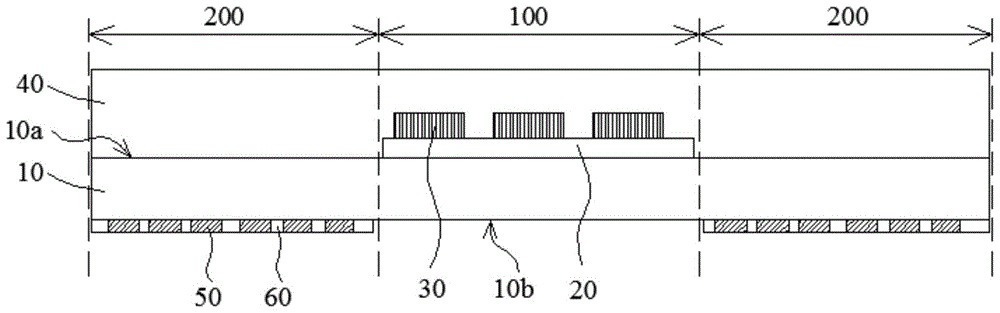
请参照图2所示,以下对本申请一种实施例提供的彩膜基板进行详细说明。所述彩膜基板包括:基底10,所述基底10可以为透光率较高的玻璃基板,或是柔性基板;第一驱动电路20,所述第一驱动电路20对应所述第一像素区域100设于所述基底10的第一表面10a上,第一驱动电路20用于为Micro LED发光单元30提供驱动信号,以使所述Micro LED发光单元30能够发光;多个Micro LED发光单元30对应所述第一像素区域100设置于所述基底10的第一表面10a一侧,且所述Micro LED发光单元30与所述第一驱动电路20电连接;封装层40设置于所述Micro LED发光单元30以及所述基底10上,用于封装所述Micro LED发光单元30;彩色色阻50对应所述第二像素区域200设于所述基底10的第二表面10b上,且相邻两所述彩色色阻50之间设置有黑色矩阵60;其中,所述彩色色阻50以及所述黑色矩阵60避开所述第一像素区域100设置。Referring to FIG. 2 , a color filter substrate provided by an embodiment of the present application will be described in detail below. The color filter substrate includes: a
其中,所述第一驱动电路20包括沿横向延伸的扫描线(未图示)和沿纵向延伸的数据线(未图示),相邻两所述扫描线与相邻两所述数据线界定出子像素区域。所述扫描线与所述数据线也可以延伸至所述第二像素区域200内,可以理解的是,为了不影响所述第二像素区域200内的像素显示,延伸至所述第二像素区域200内的所述扫描线以及所述数据线的部分避开所述彩色色阻50设置,即可以对应位于所述黑色矩阵60的位置。The
在一种实施例中,所述第一驱动电路20可以采用主动阵列(AM)驱动技术,即所述第一驱动电路20还包括薄膜晶体管(未图示),每一所述Micro LED发光单元30通过对应的所述薄膜晶体管分别与对应的所述扫描线和对应的所述数据线电连接。In an embodiment, the
在本实施例中,为优先保证所述第一像素区域100的穿透率,所述第一驱动电路20采用被动阵列(PM)驱动技术,即所述第一驱动电路20不设置薄膜晶体管。In this embodiment, in order to preferentially ensure the transmittance of the
在本实施例中,所述Micro LED发光单元30为三色显示,即所述Micro LED发光单元30包括红色发光单元、绿色发光单元以及蓝色发光单元。所述Micro LED发光单元30的尺寸为1μm-100μm,所述Micro LED发光单元30的高度为1μm-20μm。其中,所述Micro LED发光单元30可以为基底面出射结构或者电极面出射结构,此处不做限制。In this embodiment, the Micro LED light-emitting
在另一种实施例中,所述Micro LED发光单元30采用蓝色显示结合色转换技术方案,也就是说,所述红色发光单元包括蓝色发光单元以及设于所述蓝色发光单元上的色转换层,该色转换层可将所述蓝色发光单元发出的蓝光转换为红光;所述绿色发光单元包括蓝色发光单元以及设于所述蓝色发光单元上的色转换层,该色转换层可将所述蓝色发光单元发出的蓝光转换为绿光。其中,所述色转换层为量子点膜或荧光粉等,此处不做特殊限定。In another embodiment, the Micro LED light-emitting
结合图3所示,为本申请实施例提供的彩膜基板具有Micro LED发光单元的示意图。由于所述Micro LED发光单元30具有尺寸小的优势,因此所述Micro LED发光单元30在所述基底上的正投影面积小于所述子像素区域P的面积,使得多个所述Micro LED发光单元30之间具有透光区300。Referring to FIG. 3 , it is a schematic diagram of a color filter substrate having a Micro LED light-emitting unit provided in an embodiment of the present application. Since the Micro LED light-emitting
进一步的,所述Micro LED发光单元30在所述基底上的正投影面积占所述子像素区域P面积的10%-50%。Further, the orthographic projection area of the Micro LED light-emitting
在所述第一像素区域100可以实现正常显示的情况下,又由于各所述MicroLED发光单元30的覆盖面积皆小于各子像素区域P的面积,因此,在所述子像素区域P内无所述Micro LED发光单元30覆盖的区域光线可以正常透过。可以通过对所述Micro LED发光单元30关闭,使所述第一像素区域100采集外界图像进入屏下传感器。如此一来,便可实现屏下指纹识别、屏下摄像头、屏下面部识别、屏下距离感知等各种屏下传感方案。In the case where the
请参照图2所示,所述封装层40整面的设置于所述第一像素区域100和所述第二像素区域200内,所述封装层40可以为层叠的无机层和有机层,此处不做限制。所述封装层40的材料具有良好的耐高温性能以及良好的透光性。所述封装层40一方面用于对所述MicroLED发光单元30及所述第一驱动电路20进行保护和封装,避免外界水汽等进入彩膜基板内部对器件造成损伤;另一方面用于对形成有所述Micro LED发光单元30的所述基底表面进行平整化。所述封装层40的厚度为3μm-200μm,能够填平由于绑定所述Micro LED发光单元30而在基底上形成的段差。即所述封装层40背离所述基底10一侧的表面与所述基底10之间的距离大于所述Micro LED发光单元30背离所述基底10一侧的表面与所述基底10之间的距离。Referring to FIG. 2 , the
进一步的,由于所述Micro LED发光单元30的高度通常为1μm-20μm,为保证彩膜基板的轻薄化,同时兼顾封装及平坦作用,所述封装层40的厚度可以为3μm-100μm。Further, since the height of the Micro LED light-emitting
其中,所述封装层40对应所述Micro LED发光单元30的部分的厚度小于所述封装层40对应所述Micro LED发光单元30之外的部分的厚度。Wherein, the thickness of the portion of the
进一步的,所述封装层40对应所述Micro LED发光单元30的部分的厚度为2μm-80μm。因此,能够保证所述封装层40完全覆盖所述Micro LED发光单元30,以保证其良好的封装性能。Further, the thickness of the portion of the
其中,所述封装层40背离所述基底10一侧的表面为平整面,因此所述封装层40的设置还有效的解决了所述Micro LED发光单元30绑定工艺中造成的较大段差。The surface of the
为了不影响所述第一像素区域100的透光性能,所述封装层40的透光率大于或等于70%。In order not to affect the light transmittance of the
进一步的,所述封装层40的透光率大于或等于85%。Further, the light transmittance of the
在一种实施例中,所述彩色色阻50背离所述基底10的一侧设有平坦层(未图示),所述平坦层位于所述第一像素区域100和所述第二像素区域200内,所述平坦层背离所述基底10一侧的表面为平整面,如此一来,所述平坦层可以对所述基底设置有所述彩色色阻50一侧的表面进行平整化。In one embodiment, a flat layer (not shown) is provided on the side of the color resist 50 away from the
在本实施例中,所述封装层40背向所述基底10一侧还设置有保护层,所述保护层用于保护所述封装层40不受损伤。In this embodiment, a protective layer is further provided on the side of the
由于本申请的彩膜基板只在所述第一像素区域100内设置所述Micro LED发光单元30,而所述第一像素区域100的面积占比较小,因此无需依赖巨量转移的方式。如此一来,即可以实现Micro LED显示技术在显示面板/显示装置上的应用,又可以解决巨量显示画素转移时制程良率较低以及成本较高的问题。Since the color filter substrate of the present application is only provided with the Micro LED light-emitting
在Micro LED显示技术应用于显示面板上时,由于在制备Micro LED的驱动电路以及绑定Micro LED发光单元的工艺都是需要在高温下进行的,高温会对显示面板上的元器件等造成一定的不良影响;尤其是Micro LED发光单元及其驱动电路制作在彩膜基板上时,制程的高温会影响彩膜基板上彩色色阻材料的特性,从而影响显示效果。When the Micro LED display technology is applied to the display panel, the process of preparing the driving circuit of the Micro LED and binding the light-emitting unit of the Micro LED needs to be carried out at high temperature, and the high temperature will cause certain damage to the components on the display panel. In particular, when the Micro LED light-emitting unit and its driving circuit are fabricated on the color filter substrate, the high temperature of the process will affect the characteristics of the color resist material on the color filter substrate, thereby affecting the display effect.
基于此,本申请的又一目的在于提供一种彩膜基板的制备方法,以解决Micro LED发光单元及其驱动电路制作在彩膜基板上时,高温制程影响彩色色阻材料特性的问题。Based on this, another object of the present application is to provide a method for preparing a color filter substrate, so as to solve the problem that the high temperature process affects the properties of color resist materials when the Micro LED light-emitting unit and its driving circuit are fabricated on the color filter substrate.
请参照图4所示,为本申请一种实施例提供的彩膜基板的制备方法流程图。Please refer to FIG. 4 , which is a flowchart of a method for fabricating a color filter substrate according to an embodiment of the present application.
所述方法包括以下步骤:The method includes the following steps:
步骤S1,请参照图5(a)所示,在基底10的第一表面10a上对应第一像素区域100的位置制备第一驱动电路20以及与所述第一驱动电路20电连接的第一焊接电极20a,所述第一驱动电路20包括沿横向延伸的扫描线和沿纵向延伸的数据线,所述第一焊接电极20a位于相邻两所述扫描线与相邻两所述数据线界定出的子像素区域内。Step S1 , as shown in FIG. 5( a ), a
其中,所述第一焊接电极20a包括一个N电极以及一个与N电极相对设置的P电极。Wherein, the
步骤S2,请参照图5(b)所示,将Micro LED发光单元30转印于所述基底10的第一像素区域100内,且将所述Micro LED发光单元30上的第二焊接电极30a与所述第一焊接电极20a电性绑定。Step S2 , referring to FIG. 5( b ), transfer the Micro LED light-emitting
其中,所述第二焊接电极30a包括一个N电极以及一个与N电极相对设置的P电极,在绑定工艺中,所述Micro LED发光单元30的N电极与所述基底10上的N电极电连接,所述Micro LED发光单元30的P电极与所述基底10上的P电极电连接。The second welding electrode 30a includes an N electrode and a P electrode opposite to the N electrode. During the bonding process, the N electrode of the Micro LED light-emitting
步骤S3,请参照图5(c)所示,在所述Micro LED发光单元30以及所述基底10上制备封装层40。Step S3 , referring to FIG. 5( c ), an
其中,所述封装层40能够填平所述Micro LED发光单元30与所述基底10形成的段差,且所述封装层40背离所述基底10的表面形成平整面。Wherein, the
步骤S4,请参照图5(d)所示,在所述基底10的第二表面10b上制备彩色色阻50,所述彩色色阻50形成于邻近所述第一像素区域100的第二像素区域200内。Step S4 , as shown in FIG. 5( d ), a color resist 50 is prepared on the
其中,所述制备方法还包括在所述第二像素区域200内制备黑色矩阵60,所述黑色矩阵60位于相邻两所述彩色色阻50之间。所述彩色色阻50与所述黑色矩阵60制备的先后顺序此处不做限制。Wherein, the preparation method further includes preparing a
在另一种实施例中,在所述步骤S2之后,所述制备方法还包括以下步骤:In another embodiment, after the step S2, the preparation method further comprises the following steps:
在所述Micro LED发光单元上制备色转换薄膜,去除对应所述Micro LED发光单元之外的所述色转换薄膜,以形成正对所述Micro LED发光单元的色换换层。A color conversion film is prepared on the Micro LED light-emitting unit, and the color conversion film corresponding to the outside of the Micro LED light-emitting unit is removed to form a color conversion layer facing the Micro LED light-emitting unit.
由于本申请的彩膜基板是先在基底上制备第一驱动电路以及绑定Micro LED发光单元,之后再制作彩色色阻及黑色矩阵,因此,可以保证第一驱动电路制作工艺以及MicroLED发光单元绑定工艺中的高温制程不影响彩色色阻材料特性。Since the color filter substrate of the present application first prepares the first driving circuit on the substrate and binds the Micro LED light-emitting unit, and then manufactures the color resistance and the black matrix, the first driving circuit manufacturing process and the binding of the Micro LED light-emitting unit can be guaranteed. The high temperature process in the fixed process does not affect the characteristics of the color resist material.
在本申请的另一种实施例中,还提供了一种彩膜基板的制备方法,如图6所示,与上述彩膜基板的制备方法的区别仅在于步骤S2,本实施例的步骤S2中又包括两个步骤,具体如下:In another embodiment of the present application, a method for preparing a color filter substrate is also provided. As shown in FIG. 6 , the difference from the method for preparing a color filter substrate above is only in step S2, and step S2 in this embodiment is It also includes two steps, as follows:
步骤S21,请参照图7(a)所示,以Micro LED发光单元30具有电性接触区的表面30b背离所述基底10的方式将所述Micro LED发光单元30转印于所述基底10的第一像素区域100内。Step S21 , referring to FIG. 7( a ), transfer the Micro LED light-emitting
步骤S22,请参照图7(b)所示,在所述Micro LED发光单元30上制备导电薄膜,并对所述导电薄膜进行图案化,以形成电性连接所述Micro LED发光单元30的电性接触区与所述第一焊接电极20a的导电电极400。Step S22 , as shown in FIG. 7( b ), a conductive film is prepared on the Micro LED light-emitting
其中,所述电性接触区包括相对设置的N接触区和P接触区,一个所述导电电极400将N接触区与基底10上的N电极电连接,一个所述导电电极400将P接触区与基底10上的P电极电连接。Wherein, the electrical contact area includes an N contact area and a P contact area arranged oppositely, one of the
由于本实施例的彩膜基板是先在基底上制备第一驱动电路以及绑定Micro LED发光单元,之后再制作彩色色阻及黑色矩阵,因此,可以保证第一驱动电路制作工艺以及Micro LED发光单元绑定工艺中的高温制程不影响彩色色阻材料特性。另外,又由于本实施例在Micro LED发光单元绑定工艺中,Micro LED发光单元无需设置传统的焊接电极,因此,可以减小Micro LED发光单元绑定后的高度。Since the color filter substrate of this embodiment firstly prepares the first driving circuit on the substrate and binds the Micro LED light-emitting unit, and then manufactures the color resistance and the black matrix, the first driving circuit manufacturing process and the Micro LED light-emitting can be guaranteed. The high temperature process in the cell bonding process does not affect the color resistance material properties. In addition, since the Micro LED light-emitting unit does not need to be provided with traditional welding electrodes in the Micro LED light-emitting unit binding process in this embodiment, the height of the Micro LED light-emitting unit after binding can be reduced.
本申请还提供一种显示面板,如图8所示,所述显示面板包括如上所述的彩膜基板1,和阵列基板2,以及位于所述彩膜基板1与所述阵列基板2之间的液晶层3。其中,所述阵列基板2上设置有第二驱动电路21,所述第二驱动电路21设置于第二显示区域200内。由于对应显示面板的第一像素区域100内不设置所述第二驱动电路21,因此不会影响所述第一像素区域100的透光性。The present application also provides a display panel. As shown in FIG. 8 , the display panel includes the above-mentioned color filter substrate 1 and an
本申请还提供一种显示装置,如图9所示,所述显示装置包括如上所述的显示面板,以及背光模组4和传感器组件5。所述背光模组4对应第一像素区域100设有通孔41,所述传感器组件5正对所述通孔41设置。The present application further provides a display device, as shown in FIG. 9 , the display device includes the above-mentioned display panel, a
其中,所述传感器组件5为光学式传感器,可以实现面部识别、距离感应、指纹识别等,此处不做限制。Wherein, the
综上所述,本申请提供的彩膜基板及其制备方法、显示面板、显示装置,通过采用微发光二极管显示技术与液晶显示技术相结合的形式,从而可以实现LCD极致全面屏显示。又由于彩膜基板在相邻两所述Micro LED发光单元之间设有透光区,所述透光区可以允许光线穿过,因此可以实现屏内传感集成方案。另外,由于本申请的彩膜基板是先在基底上制备第一驱动电路以及绑定Micro LED发光单元,之后再制作彩色色阻及黑色矩阵,因此,可以保证第一驱动电路制作工艺以及Micro LED发光单元绑定工艺中的高温制程不影响彩色色阻材料特性。To sum up, the color filter substrate and its preparation method, display panel, and display device provided by the present application can realize the ultimate full-screen display of LCD by adopting the combination of micro-light-emitting diode display technology and liquid crystal display technology. In addition, since the color filter substrate is provided with a light-transmitting area between two adjacent Micro LED light-emitting units, the light-transmitting area can allow light to pass through, so an integrated solution for in-screen sensing can be realized. In addition, since the color filter substrate of the present application first prepares the first driving circuit and binds the Micro LED light-emitting unit on the substrate, and then manufactures the color resistance and black matrix, the first driving circuit manufacturing process and the Micro LED can be guaranteed. The high temperature process in the light emitting unit bonding process does not affect the characteristics of the color resist material.
综上所述,虽然本申请已以优选实施例揭露如上,但上述优选实施例并非用以限制本申请,本领域的普通技术人员,在不脱离本申请的精神和范围内,均可作各种更动与润饰,因此本申请的保护范围以权利要求界定的范围为准。To sum up, although the present application has disclosed the above-mentioned preferred embodiments, the above-mentioned preferred embodiments are not intended to limit the present application. Those of ordinary skill in the art, without departing from the spirit and scope of this application, can Therefore, the scope of protection of the present application is subject to the scope defined by the claims.
Claims (10)
Priority Applications (3)
| Application Number | Priority Date | Filing Date | Title |
|---|---|---|---|
| CN202010485380.8A CN111596484A (en) | 2020-06-01 | 2020-06-01 | Color film substrate and display panel |
| PCT/CN2020/097618 WO2021243766A1 (en) | 2020-06-01 | 2020-06-23 | Color film substrate and display panel |
| US16/969,562 US11994778B2 (en) | 2020-06-01 | 2020-06-23 | Color filter substrate and display panel |
Applications Claiming Priority (1)
| Application Number | Priority Date | Filing Date | Title |
|---|---|---|---|
| CN202010485380.8A CN111596484A (en) | 2020-06-01 | 2020-06-01 | Color film substrate and display panel |
Publications (1)
| Publication Number | Publication Date |
|---|---|
| CN111596484A true CN111596484A (en) | 2020-08-28 |
Family
ID=72185976
Family Applications (1)
| Application Number | Title | Priority Date | Filing Date |
|---|---|---|---|
| CN202010485380.8A Pending CN111596484A (en) | 2020-06-01 | 2020-06-01 | Color film substrate and display panel |
Country Status (3)
| Country | Link |
|---|---|
| US (1) | US11994778B2 (en) |
| CN (1) | CN111596484A (en) |
| WO (1) | WO2021243766A1 (en) |
Cited By (8)
| Publication number | Priority date | Publication date | Assignee | Title |
|---|---|---|---|---|
| CN111653585A (en) * | 2020-06-19 | 2020-09-11 | 武汉华星光电技术有限公司 | Display panel, method for producing the same, and display device |
| CN113053254A (en) * | 2021-03-05 | 2021-06-29 | 武汉华星光电技术有限公司 | Display panel, manufacturing method thereof and display device |
| CN113345927A (en) * | 2021-05-31 | 2021-09-03 | 武汉华星光电技术有限公司 | Method for preparing display panel and transparent display area of camera under screen |
| CN113437114A (en) * | 2021-06-02 | 2021-09-24 | Tcl华星光电技术有限公司 | Display device and preparation method thereof |
| WO2021248783A1 (en) * | 2020-06-08 | 2021-12-16 | 武汉华星光电技术有限公司 | Color film substrate, display panel, and display device |
| TWI770813B (en) * | 2021-02-08 | 2022-07-11 | 友達光電股份有限公司 | Display apparatus and manufacturing method thereof |
| US20220328719A1 (en) * | 2021-04-12 | 2022-10-13 | Seoul Viosys Co., Ltd | Light emitting device and light emitting module having the same |
| WO2023004564A1 (en) * | 2021-07-27 | 2023-02-02 | 重庆康佳光电技术研究院有限公司 | Display panel, display screen, electronic device, and control method therefor |
Families Citing this family (2)
| Publication number | Priority date | Publication date | Assignee | Title |
|---|---|---|---|---|
| US12364073B2 (en) * | 2020-06-08 | 2025-07-15 | Seoul Viosys Co., Ltd. | Unit pixel having light emitting device and displaying apparatus |
| FR3153931A1 (en) * | 2023-10-04 | 2025-04-11 | Valeo Comfort And Driving Assistance | Combined system forming a screen |
Citations (6)
| Publication number | Priority date | Publication date | Assignee | Title |
|---|---|---|---|---|
| CN110275340A (en) * | 2019-06-10 | 2019-09-24 | 武汉华星光电技术有限公司 | For shielding the liquid crystal display of lower identification scheme |
| CN110543050A (en) * | 2019-09-30 | 2019-12-06 | 上海天马微电子有限公司 | A display panel, a display device, and a compensation method for the display device |
| CN110568649A (en) * | 2019-09-10 | 2019-12-13 | 武汉华星光电技术有限公司 | display device and driving method thereof |
| CN110632789A (en) * | 2019-08-22 | 2019-12-31 | 武汉华星光电技术有限公司 | Display device |
| CN110794604A (en) * | 2019-11-29 | 2020-02-14 | 武汉华星光电技术有限公司 | Display device and manufacturing method thereof |
| CN212276177U (en) * | 2020-06-01 | 2021-01-01 | 武汉华星光电技术有限公司 | Color film substrate and display panel |
Family Cites Families (12)
| Publication number | Priority date | Publication date | Assignee | Title |
|---|---|---|---|---|
| CN107025848A (en) * | 2017-06-05 | 2017-08-08 | 京东方科技集团股份有限公司 | A kind of display base plate, display panel, display device and preparation method |
| US20190137814A1 (en) * | 2017-11-03 | 2019-05-09 | HKC Corporation Limited | Display panel and method of manufacturing the same |
| CN108732816B (en) | 2018-05-22 | 2021-06-25 | 武汉华星光电技术有限公司 | Area source backlight module and liquid crystal display panel |
| CN109116619A (en) * | 2018-09-26 | 2019-01-01 | 京东方科技集团股份有限公司 | Color membrane substrates, display panel, mask plate |
| CN110231735B (en) * | 2019-05-16 | 2023-08-22 | 武汉华星光电技术有限公司 | display device |
| US11061265B2 (en) * | 2019-12-09 | 2021-07-13 | Shenzhen China Star Optoelectronics Semiconductor Display Technology Co., Ltd. | COA substrate and display panel |
| US11411149B2 (en) * | 2020-03-12 | 2022-08-09 | Shenzhen China Star Optoelectronics Semiconductor Display Technology Co., Ltd. | Array substrate, display panel, and manufacturing method of display panel |
| CN111399275A (en) * | 2020-04-15 | 2020-07-10 | 深圳市华星光电半导体显示技术有限公司 | Display panel and display device |
| CN111596485A (en) * | 2020-06-08 | 2020-08-28 | 武汉华星光电技术有限公司 | A color filter substrate, a display panel, and a display device |
| CN111708196A (en) * | 2020-06-23 | 2020-09-25 | 武汉华星光电技术有限公司 | Display panel and display device |
| CN112764260B (en) * | 2021-01-15 | 2023-10-17 | Tcl华星光电技术有限公司 | Liquid crystal display panel and liquid crystal display device |
| CN113345336B (en) * | 2021-05-31 | 2023-06-06 | 上海天马微电子有限公司 | A display panel and its manufacturing method |
-
2020
- 2020-06-01 CN CN202010485380.8A patent/CN111596484A/en active Pending
- 2020-06-23 WO PCT/CN2020/097618 patent/WO2021243766A1/en not_active Ceased
- 2020-06-23 US US16/969,562 patent/US11994778B2/en active Active
Patent Citations (6)
| Publication number | Priority date | Publication date | Assignee | Title |
|---|---|---|---|---|
| CN110275340A (en) * | 2019-06-10 | 2019-09-24 | 武汉华星光电技术有限公司 | For shielding the liquid crystal display of lower identification scheme |
| CN110632789A (en) * | 2019-08-22 | 2019-12-31 | 武汉华星光电技术有限公司 | Display device |
| CN110568649A (en) * | 2019-09-10 | 2019-12-13 | 武汉华星光电技术有限公司 | display device and driving method thereof |
| CN110543050A (en) * | 2019-09-30 | 2019-12-06 | 上海天马微电子有限公司 | A display panel, a display device, and a compensation method for the display device |
| CN110794604A (en) * | 2019-11-29 | 2020-02-14 | 武汉华星光电技术有限公司 | Display device and manufacturing method thereof |
| CN212276177U (en) * | 2020-06-01 | 2021-01-01 | 武汉华星光电技术有限公司 | Color film substrate and display panel |
Cited By (12)
| Publication number | Priority date | Publication date | Assignee | Title |
|---|---|---|---|---|
| WO2021248783A1 (en) * | 2020-06-08 | 2021-12-16 | 武汉华星光电技术有限公司 | Color film substrate, display panel, and display device |
| US11977292B2 (en) | 2020-06-08 | 2024-05-07 | Wuhan China Star Optoelectronics Technology Co., Ltd. | Color filter substrate, display panel, and display device |
| CN111653585A (en) * | 2020-06-19 | 2020-09-11 | 武汉华星光电技术有限公司 | Display panel, method for producing the same, and display device |
| WO2021253560A1 (en) * | 2020-06-19 | 2021-12-23 | 武汉华星光电技术有限公司 | Display panel and preparation method therefor, and display device |
| TWI770813B (en) * | 2021-02-08 | 2022-07-11 | 友達光電股份有限公司 | Display apparatus and manufacturing method thereof |
| CN113053254A (en) * | 2021-03-05 | 2021-06-29 | 武汉华星光电技术有限公司 | Display panel, manufacturing method thereof and display device |
| US20220328719A1 (en) * | 2021-04-12 | 2022-10-13 | Seoul Viosys Co., Ltd | Light emitting device and light emitting module having the same |
| US12490552B2 (en) * | 2021-04-12 | 2025-12-02 | Seoul Viosys Co., Ltd. | Light emitting device and light emitting module having the same |
| CN113345927A (en) * | 2021-05-31 | 2021-09-03 | 武汉华星光电技术有限公司 | Method for preparing display panel and transparent display area of camera under screen |
| CN113437114A (en) * | 2021-06-02 | 2021-09-24 | Tcl华星光电技术有限公司 | Display device and preparation method thereof |
| CN113437114B (en) * | 2021-06-02 | 2022-12-06 | Tcl华星光电技术有限公司 | Display device and preparation method thereof |
| WO2023004564A1 (en) * | 2021-07-27 | 2023-02-02 | 重庆康佳光电技术研究院有限公司 | Display panel, display screen, electronic device, and control method therefor |
Also Published As
| Publication number | Publication date |
|---|---|
| US20230099140A1 (en) | 2023-03-30 |
| WO2021243766A1 (en) | 2021-12-09 |
| US11994778B2 (en) | 2024-05-28 |
Similar Documents
| Publication | Publication Date | Title |
|---|---|---|
| CN111596484A (en) | Color film substrate and display panel | |
| US11256121B2 (en) | Liquid crystal display device for under-screen identification scheme | |
| US12284892B2 (en) | Display substrate and display device | |
| US11977292B2 (en) | Color filter substrate, display panel, and display device | |
| US10764973B2 (en) | Display device and electronic device | |
| WO2021258489A1 (en) | Display panel and display device | |
| CN109300951B (en) | Display panel, manufacturing method thereof and electronic equipment | |
| CN212276177U (en) | Color film substrate and display panel | |
| WO2021103390A1 (en) | Display apparatus and method for manufacturing display apparatus | |
| CN109037270B (en) | A display panel and display device | |
| CN112864214B (en) | Display module and display device | |
| CN113130619A (en) | Display substrate, display panel and display device | |
| CN112951106A (en) | Display device | |
| CN114284322A (en) | Display panel and display device | |
| CN205487282U (en) | Display module assembly, display device | |
| US11536995B2 (en) | Display panel and display device | |
| CN212276178U (en) | Color film substrate, display panel and display device | |
| CN218101267U (en) | display device | |
| CN116782723A (en) | Display panel, preparation method and display device thereof | |
| US11980061B2 (en) | OLED display panel and manufacturing method thereof | |
| US20250318384A1 (en) | Display device | |
| US20240206239A1 (en) | Display device | |
| KR20250128188A (en) | Display device and manufacturing method of the same | |
| KR20240015791A (en) | Display device and electronic device having the same |
Legal Events
| Date | Code | Title | Description |
|---|---|---|---|
| PB01 | Publication | ||
| PB01 | Publication | ||
| SE01 | Entry into force of request for substantive examination | ||
| SE01 | Entry into force of request for substantive examination |