CN109300951B - Display panel, manufacturing method thereof and electronic equipment - Google Patents
Display panel, manufacturing method thereof and electronic equipment Download PDFInfo
- Publication number
- CN109300951B CN109300951B CN201811155876.8A CN201811155876A CN109300951B CN 109300951 B CN109300951 B CN 109300951B CN 201811155876 A CN201811155876 A CN 201811155876A CN 109300951 B CN109300951 B CN 109300951B
- Authority
- CN
- China
- Prior art keywords
- pixel
- area
- micro led
- display area
- signal line
- Prior art date
- Legal status (The legal status is an assumption and is not a legal conclusion. Google has not performed a legal analysis and makes no representation as to the accuracy of the status listed.)
- Active
Links
- 238000004519 manufacturing process Methods 0.000 title claims abstract description 32
- 239000000758 substrate Substances 0.000 claims abstract description 50
- 239000010409 thin film Substances 0.000 claims description 10
- 230000003287 optical effect Effects 0.000 abstract description 31
- 230000000694 effects Effects 0.000 abstract description 9
- 239000010410 layer Substances 0.000 description 92
- 238000000034 method Methods 0.000 description 34
- 238000010586 diagram Methods 0.000 description 5
- 239000012044 organic layer Substances 0.000 description 3
- 238000002834 transmittance Methods 0.000 description 3
- 230000009286 beneficial effect Effects 0.000 description 2
- 239000003990 capacitor Substances 0.000 description 2
- 238000001704 evaporation Methods 0.000 description 2
- 239000010408 film Substances 0.000 description 2
- 238000002360 preparation method Methods 0.000 description 2
- 230000005540 biological transmission Effects 0.000 description 1
- 230000015572 biosynthetic process Effects 0.000 description 1
- 239000011248 coating agent Substances 0.000 description 1
- 238000000576 coating method Methods 0.000 description 1
- 238000013461 design Methods 0.000 description 1
- 238000011161 development Methods 0.000 description 1
- AMGQUBHHOARCQH-UHFFFAOYSA-N indium;oxotin Chemical compound [In].[Sn]=O AMGQUBHHOARCQH-UHFFFAOYSA-N 0.000 description 1
- 239000004973 liquid crystal related substance Substances 0.000 description 1
- 238000004020 luminiscence type Methods 0.000 description 1
- 239000000463 material Substances 0.000 description 1
- 238000012986 modification Methods 0.000 description 1
- 230000004048 modification Effects 0.000 description 1
- 230000005693 optoelectronics Effects 0.000 description 1
- 230000000750 progressive effect Effects 0.000 description 1
- 238000012546 transfer Methods 0.000 description 1
Images


Classifications
-
- H—ELECTRICITY
- H10—SEMICONDUCTOR DEVICES; ELECTRIC SOLID-STATE DEVICES NOT OTHERWISE PROVIDED FOR
- H10K—ORGANIC ELECTRIC SOLID-STATE DEVICES
- H10K59/00—Integrated devices, or assemblies of multiple devices, comprising at least one organic light-emitting element covered by group H10K50/00
- H10K59/30—Devices specially adapted for multicolour light emission
- H10K59/35—Devices specially adapted for multicolour light emission comprising red-green-blue [RGB] subpixels
-
- H—ELECTRICITY
- H10—SEMICONDUCTOR DEVICES; ELECTRIC SOLID-STATE DEVICES NOT OTHERWISE PROVIDED FOR
- H10H—INORGANIC LIGHT-EMITTING SEMICONDUCTOR DEVICES HAVING POTENTIAL BARRIERS
- H10H29/00—Integrated devices, or assemblies of multiple devices, comprising at least one light-emitting semiconductor element covered by group H10H20/00
- H10H29/10—Integrated devices comprising at least one light-emitting semiconductor component covered by group H10H20/00
- H10H29/14—Integrated devices comprising at least one light-emitting semiconductor component covered by group H10H20/00 comprising multiple light-emitting semiconductor components
- H10H29/142—Two-dimensional arrangements, e.g. asymmetric LED layout
-
- H—ELECTRICITY
- H10—SEMICONDUCTOR DEVICES; ELECTRIC SOLID-STATE DEVICES NOT OTHERWISE PROVIDED FOR
- H10K—ORGANIC ELECTRIC SOLID-STATE DEVICES
- H10K59/00—Integrated devices, or assemblies of multiple devices, comprising at least one organic light-emitting element covered by group H10K50/00
- H10K59/10—OLED displays
- H10K59/12—Active-matrix OLED [AMOLED] displays
- H10K59/1201—Manufacture or treatment
Landscapes
- Engineering & Computer Science (AREA)
- Microelectronics & Electronic Packaging (AREA)
- Manufacturing & Machinery (AREA)
- Electroluminescent Light Sources (AREA)
- Devices For Indicating Variable Information By Combining Individual Elements (AREA)
Abstract
本发明公开了一种显示面板及其制作方法以及电子设备,设置阵列基板的显示区包括第一显示区以及第二显示区,在第一显示区设置的第一像素区内设置OLED像素,位于第二显示区的第二像素区包括发光区以及透明区,在发光区设置Micro LED像素,这样,可以在第二显示区的背离出光侧的一侧设置光学电子元件,光学电子元件通过位于第二显示区的透明区采集光信号,无需在显示面板上设置挖空区域,避免了由此导致的显示区面积减小问题,保证了图像的显示效果。
The invention discloses a display panel, a manufacturing method thereof, and an electronic device. A display area where an array substrate is arranged includes a first display area and a second display area, and OLED pixels are arranged in the first pixel area arranged in the first display area. The second pixel area of the second display area includes a light-emitting area and a transparent area. Micro LED pixels are arranged in the light-emitting area. In this way, an optical and electronic element can be arranged on the side of the second display area away from the light-emitting side. The transparent area of the second display area collects light signals, and there is no need to set a hollow area on the display panel, which avoids the problem of reducing the area of the display area and ensures the display effect of the image.
Description
技术领域technical field
本发明涉及显示技术领域,更具体的说,涉及一种显示面板及其制作方法以及电子设备。The present invention relates to the field of display technology, and more particularly, to a display panel, a manufacturing method thereof, and an electronic device.
背景技术Background technique
随着科学技术的不断发展,越来越多的具有显示功能的电子设备被广泛的应用于人们的日常生活以及工作当中,为人们如日常生活以及工作带来了巨大的便利,成为当今人们不可或缺的重要工具。With the continuous development of science and technology, more and more electronic devices with display function are widely used in people's daily life and work, which brings great convenience to people's daily life and work, and has become an indispensable part of today's people. important tool that is missing.
电子设备实现显示功能的重要部件是显示面板。现有的显示面板中,为了适应电子设备集成光学电子元件的需求,需要在显示面板的设定区域设置挖空区域,用于设置所述光学电子元件。例如,现有的全面屏智能手机需要设置前置摄像头以及光学传感器等光学电子元件,需要在手机的显示面板的上端中间位置设置挖空区域,在挖空区域内设置光学电子元件。An important part of an electronic device to realize the display function is the display panel. In the existing display panel, in order to meet the requirement of integrating optical electronic components in electronic devices, it is necessary to set a hollow area in the setting area of the display panel for setting the optical electronic components. For example, an existing full-screen smartphone needs to be equipped with optical electronic components such as a front camera and an optical sensor. It is necessary to set a hollow area in the middle of the upper end of the display panel of the mobile phone, and set the optical electronic components in the hollow area.
如上述,现有电子设备中需要在显示面板上设置挖空区域,以设置光学电子元件,降低了显示区的面积,使得图象显示效果较差。As mentioned above, in the existing electronic equipment, a hollow area needs to be arranged on the display panel to arrange the optical electronic components, which reduces the area of the display area and makes the image display effect poor.
发明内容SUMMARY OF THE INVENTION
为了解决上述问题,本发明技术方案提供了一种显示面板及其制作方法以及电子设备,可以在第二显示区的背面设置光学电子元件,无需在显示面板上设置挖空区域,提高了显示区的面积,保证了图像的显示效果。In order to solve the above problems, the technical solution of the present invention provides a display panel, a manufacturing method thereof, and an electronic device. Optical electronic components can be arranged on the back of the second display area, and there is no need to set a hollow area on the display panel, which improves the display area. area to ensure the display effect of the image.
为了实现上述目的,本发明提供如下技术方案:In order to achieve the above object, the present invention provides the following technical solutions:
一种显示面板,所述显示面板包括:A display panel comprising:
阵列基板,所述阵列基板具有显示区;所述显示区分为第一显示区以及第二显示区;所述第一显示区具有多个第一像素区;所述第二显示区具有多个第二像素区;所述第二像素区包括发光区和透明区;an array substrate, the array substrate has a display area; the display area is divided into a first display area and a second display area; the first display area has a plurality of first pixel areas; the second display area has a plurality of first display areas Two pixel areas; the second pixel area includes a light-emitting area and a transparent area;
固定在所述发光区的Micro LED像素;Micro LED pixels fixed in the light-emitting area;
覆盖所述显示区的像素定义层,所述像素定义层包括覆盖所述第一显示区的第一部分以及覆盖所述第二显示区的第二部分;所述第二部分覆盖所述Micro LED像素的至少一部分;其中,所述第一部分设置有多个开口,所述开口与所述第一像素区一一对应;a pixel definition layer covering the display area, the pixel definition layer including a first part covering the first display area and a second part covering the second display area; the second part covering the Micro LED pixels At least a part of the ; wherein, the first part is provided with a plurality of openings, and the openings correspond to the first pixel regions one-to-one;
形成在所述开口内的OLED像素。OLED pixels are formed within the openings.
可选的,在上述显示面板中,所述阵列基板包括:Optionally, in the above display panel, the array substrate includes:
透明基板;transparent substrate;
设置在所述透明基板与所述像素定义层之间的第一导电层,所述第一导电层包括所述OLED像素的阳极,所述第一导电层还包括所述Micro LED像素的阳极和阴极中的至少一者;a first conductive layer disposed between the transparent substrate and the pixel definition layer, the first conductive layer includes the anode of the OLED pixel, the first conductive layer further includes the anode of the Micro LED pixel and the at least one of the cathodes;
其中,所述第一像素区内设置有所述OLED像素的阳极,所述开口露出至少部分所述OLED像素的阳极。Wherein, the anode of the OLED pixel is disposed in the first pixel region, and the opening exposes at least part of the anode of the OLED pixel.
可选的,在上述显示面板中,所述第一导电层包括所述Micro LED像素的阳极和阴极中的一者;Optionally, in the above display panel, the first conductive layer includes one of an anode and a cathode of the Micro LED pixel;
所述像素定义层背离所述阵列基板的一侧设置有第二导电层,所述第二导电层包括所述OLED像素的阴极,所述第二导电层还包括所述Micro LED像素的阳极和阴极中的另一者;A second conductive layer is disposed on the side of the pixel definition layer away from the array substrate, the second conductive layer includes the cathode of the OLED pixel, and the second conductive layer further includes the anode of the Micro LED pixel and the the other of the cathodes;
所述像素定义层具有电极通孔,所述第二导电层通过所述电极通孔与所述MicroLED像素电连接。The pixel definition layer has electrode through holes, and the second conductive layer is electrically connected to the MicroLED pixels through the electrode through holes.
可选的,在上述显示面板中,所述第一导电层还包括信号线;Optionally, in the above display panel, the first conductive layer further includes a signal line;
所述像素定义层还具有连接开口,所述连接开口至少露出部分所述信号线,与所述Micro LED像素电连接的第二导电层通过所述连接开口与所述信号线电连接。The pixel definition layer further has a connection opening, the connection opening exposes at least part of the signal line, and the second conductive layer electrically connected to the Micro LED pixel is electrically connected to the signal line through the connection opening.
可选的,在上述显示面板中,所述第一导电层包括所述Micro LED像素的阳极和阴极;Optionally, in the above display panel, the first conductive layer includes an anode and a cathode of the Micro LED pixel;
所述像素定义层背离所述阵列基板的一侧设置有第二导电层,所述第二导电层包括:所述OLED像素的阴极。A second conductive layer is disposed on the side of the pixel definition layer away from the array substrate, and the second conductive layer includes: a cathode of the OLED pixel.
可选的,在上述显示面板中,所述阵列基板还包括功能电路,所述功能电路位于所述第一导电层与所述透明基板之间;Optionally, in the above display panel, the array substrate further includes a functional circuit, and the functional circuit is located between the first conductive layer and the transparent substrate;
所述Micro LED像素采用有源驱动方式;The Micro LED pixel adopts an active driving method;
所述功能电路包括:第一驱动电路,所述第一驱动电路位于所述第一像素区内,用于驱动所述OLED像素进行发光显示;第二驱动电路,所述第二驱动电路位于所述发光区内,用于驱动所述Micro LED像素进行发光显示;The functional circuit includes: a first driving circuit, which is located in the first pixel area and is used to drive the OLED pixels to emit light and display; a second driving circuit, which is located in the first pixel area. The light-emitting area is used to drive the Micro LED pixels to perform light-emitting display;
其中,所述第一驱动电路中薄膜晶体管的数量大于所述第二驱动电路中薄膜晶体管的数量。Wherein, the number of thin film transistors in the first driving circuit is greater than the number of thin film transistors in the second driving circuit.
可选的,在上述显示面板中,所述阵列基板还包括功能电路,所述功能电路位于所述第一导电层与所述透明基板之间;Optionally, in the above display panel, the array substrate further includes a functional circuit, and the functional circuit is located between the first conductive layer and the transparent substrate;
所述Micro LED像素采用无源驱动方式;所述Micro LED像素的阳极与第一信号线连接,所述Micro LED像素的阴极与第二信号线连接,所述第一信号线与所述第二信号线用于为所述Micro LED像素提供发光电压信号;The Micro LED pixel adopts a passive driving method; the anode of the Micro LED pixel is connected to the first signal line, the cathode of the Micro LED pixel is connected to the second signal line, and the first signal line is connected to the second signal line. The signal line is used to provide a light-emitting voltage signal for the Micro LED pixel;
所述功能电路包括:第一驱动电路,所述第一驱动电路位于所述第一像素区内,用于驱动所述OLED像素进行发光显示。The functional circuit includes: a first driving circuit, and the first driving circuit is located in the first pixel region and is used for driving the OLED pixels to perform light-emitting display.
可选的,在上述显示面板中,所述第一导电层包括所述第一信号线以及所述第二信号线;Optionally, in the above display panel, the first conductive layer includes the first signal line and the second signal line;
所述第一信号线与所述第二信号线相互绝缘且交叉设置,二者交叉位置具有跨桥。The first signal line and the second signal line are insulated from each other and arranged to cross each other, and there is a bridge at the cross position of the two.
可选的,在上述显示面板中,所述第二像素区阵列排布;Optionally, in the above-mentioned display panel, the second pixel regions are arranged in an array;
所述第一信号线连接同一行所述第二像素区内的所述Micro LED像素的阳极,所述第二信号线连接同一列所述第二像素区内的所述Micro LED像素的阴极;the first signal line is connected to the anodes of the Micro LED pixels in the second pixel region of the same row, and the second signal line is connected to the cathodes of the Micro LED pixels in the second pixel region of the same column;
或,所述第一信号线连接同一列所述第二像素区内的所述Micro LED像素的阳极,所述第二信号线连接同一行所述第二像素区内的所述Micro LED像素的阴极。Or, the first signal line is connected to the anodes of the Micro LED pixels in the second pixel region of the same column, and the second signal line is connected to the Micro LED pixels in the second pixel region of the same row. cathode.
本发明还提供了一种显示面板的制作方法,所述制作方法包括:The present invention also provides a manufacturing method of a display panel, the manufacturing method comprising:
提供一阵列基板,所述阵列基板具有显示区,所述显示区分为第一显示区以及第二显示区;所述第一显示区具有多个第一像素区;所述第二显示区具有多个第二像素区;所述第二像素区包括发光区和透明区;An array substrate is provided, the array substrate has a display area, the display area is divided into a first display area and a second display area; the first display area has a plurality of first pixel areas; the second display area has a plurality of a second pixel area; the second pixel area includes a light-emitting area and a transparent area;
在所述发光区放置Micro LED像素;Place Micro LED pixels in the light-emitting area;
形成覆盖所述显示区的像素定义层,所述像素定义层包括覆盖所述第一显示区的第一部分以及覆盖所述第二显示区的第二部分;所述第二部分覆盖所述Micro LED像素的至少一部分;其中,所述第一部分设置有多个开口,所述开口与所述第一像素区一一对应;forming a pixel definition layer covering the display area, the pixel definition layer including a first part covering the first display area and a second part covering the second display area; the second part covering the Micro LED At least a part of a pixel; wherein, the first part is provided with a plurality of openings, and the openings correspond to the first pixel regions one-to-one;
在所述开口内形成OLED像素。OLED pixels are formed within the openings.
本发明还提供了一种电子设备,所述电子设备包括上述任一项所述的显示面板。The present invention also provides an electronic device, which includes the display panel described in any one of the above.
通过上述描述可知,本发明实施例提供的显示面板及其制作方法以及电子设备中,设置阵列基板的显示区包括第一显示区以及第二显示区,在第一显示区设置的第一像素区内设置OLED像素,位于第二显示区的第二像素区包括发光区以及透明区,在发光区设置Micro LED像素,这样,可以在第二显示区的背离出光侧的一侧设置光学电子元件,光学电子元件通过位于第二显示区的透明区采集光信号,无需在显示面板上设置挖空区域,避免了由此导致的显示区面积减小问题,保证了图像的显示效果。It can be seen from the above description that in the display panel and the manufacturing method thereof and the electronic device provided by the embodiments of the present invention, the display area where the array substrate is arranged includes the first display area and the second display area, and the first pixel area arranged in the first display area OLED pixels are arranged inside, the second pixel area located in the second display area includes a light-emitting area and a transparent area, and Micro LED pixels are arranged in the light-emitting area, so that optical electronic components can be arranged on the side of the second display area away from the light-emitting side, The optical electronic element collects light signals through the transparent area located in the second display area, and there is no need to set a hollow area on the display panel, which avoids the problem of reducing the area of the display area and ensures the display effect of the image.
附图说明Description of drawings
为了更清楚地说明本发明实施例或现有技术中的技术方案,下面将对实施例或现有技术描述中所需要使用的附图作简单地介绍,显而易见地,下面描述中的附图仅仅是本发明的实施例,对于本领域普通技术人员来讲,在不付出创造性劳动的前提下,还可以根据提供的附图获得其他的附图。In order to explain the embodiments of the present invention or the technical solutions in the prior art more clearly, the following briefly introduces the accompanying drawings that need to be used in the description of the embodiments or the prior art. Obviously, the accompanying drawings in the following description are only It is an embodiment of the present invention. For those of ordinary skill in the art, other drawings can also be obtained according to the provided drawings without creative work.
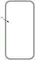
图1为现有一种全面屏智能手机的显示面板的俯视图;1 is a top view of a display panel of an existing full-screen smartphone;
图2为本发明实施例提供的一种显示面板的俯视图;FIG. 2 is a top view of a display panel according to an embodiment of the present invention;
图3为图2所示液晶显示面板中的像素布局示意图;FIG. 3 is a schematic diagram of a pixel layout in the liquid crystal display panel shown in FIG. 2;
图4为图2在P-P’方向的一种切面图;Fig. 4 is a kind of sectional view of Fig. 2 in P-P' direction;
图5为图2在P-P’方向的另一种切面图;Fig. 5 is another sectional view of Fig. 2 in P-P' direction;
图6为图2在P-P’方向的又一种切面图;Fig. 6 is another kind of sectional view of Fig. 2 in P-P' direction;
图7为本发明实施例提供的一种制作方法的流程示意图;7 is a schematic flowchart of a manufacturing method according to an embodiment of the present invention;
图8为本发明实施例提供的一种电子设备的结构示意图。FIG. 8 is a schematic structural diagram of an electronic device according to an embodiment of the present invention.
具体实施方式Detailed ways
下面将结合本发明实施例中的附图,对本发明实施例中的技术方案进行清楚、完整地描述,显然,所描述的实施例仅仅是本发明一部分实施例,而不是全部的实施例。基于本发明中的实施例,本领域普通技术人员在没有做出创造性劳动前提下所获得的所有其他实施例,都属于本发明保护的范围。The technical solutions in the embodiments of the present invention will be clearly and completely described below with reference to the accompanying drawings in the embodiments of the present invention. Obviously, the described embodiments are only a part of the embodiments of the present invention, but not all of the embodiments. Based on the embodiments of the present invention, all other embodiments obtained by those of ordinary skill in the art without creative efforts shall fall within the protection scope of the present invention.
参考图1,图1为现有一种全面屏智能手机的显示面板的俯视图,图1所示方式中,为了在智能手机中集成前置摄像头以及光学传感器等光学电子元件,需要在显示面板的预设长度的上端部分11设置挖空区域111,用于设置所述光学电子元件。显示面板上端的肩部112和肩部113一般用于显示辅助提示信息,如用于显示电池电量、网络连接方式以及信号流量等。Referring to FIG. 1, FIG. 1 is a top view of a display panel of an existing full-screen smartphone. In the method shown in FIG. 1, in order to integrate optical electronic components such as a front camera and an optical sensor in the smartphone, it is necessary to pre-install the display panel. The length-providing
由于上端部分11具有挖空区域111,挖空区域111不能显示图像,这样,当全屏显示时(如全屏视频播界面放或是全屏游戏界面),会导致显示图像有缺失,影响图像显示效果。Since the
为了解决上述问题,本发明实施例提供了一种显示面板,设置一第二显示区,设置第二显示区内的像素区包括发光区以及透明区,在发光区设置Micro LED像素,这样,可以在第二显示区的背离出光侧的一侧设置光学电子元件,光学电子元件通过位于第二显示区的透明区采集光信号,无需在显示面板上设置挖空区域,真正实现了全面屏显示,避免了由此导致的显示区面积减小问题,保证了图像的显示效果。In order to solve the above problem, an embodiment of the present invention provides a display panel, a second display area is provided, the pixel area in the second display area includes a light-emitting area and a transparent area, and Micro LED pixels are arranged in the light-emitting area. An optical electronic element is arranged on the side of the second display area away from the light-emitting side, and the optical electronic element collects the light signal through the transparent area located in the second display area, and there is no need to set a hollow area on the display panel, and a full-screen display is truly realized. The problem of reducing the area of the display area caused thereby is avoided, and the display effect of the image is guaranteed.
为使本发明的上述目的、特征和优点能够更加明显易懂,下面结合附图和具体实施方式对本发明作进一步详细的说明。In order to make the above objects, features and advantages of the present invention more clearly understood, the present invention will be described in further detail below with reference to the accompanying drawings and specific embodiments.
参考图2-图4,图2为本发明实施例提供的一种显示面板的俯视图,图3为图2所示显示面板中的像素布局示意图,图4为图2在P-P’方向的一种切面图。Referring to FIGS. 2-4 , FIG. 2 is a top view of a display panel according to an embodiment of the present invention, FIG. 3 is a schematic diagram of a pixel layout in the display panel shown in FIG. 2 , and FIG. 4 is a view of FIG. 2 in the PP' direction. A cutaway diagram.
本发明实施例所述显示面板包括:阵列基板21,所述阵列基板21具有显示区22。所述显示区分22为第一显示区221以及第二显示区222。所述第一显示区221具有多个第一像素区2211,所述第二显示区222具有多个第二像素区2221,所述第二像素区2221包括发光区a和透明区b。在图3所示方式中,第二显示区222背离出光侧的一侧用于设置一个光学电子元件26,该光学电子元件26可以为摄像头,此时该光学电子元件的尺寸与所述第二显示区222的尺寸匹配,由于摄像头的尺寸相对于像素的尺寸较大,故可以对应多个第二像素区2221的透明区b。其他方式中,所述第二显示区222的背面还可以对应设置多个不同类型的光学电子元件26。每个光学电子元件26与多个第二像素区2221的透明区b对应设置。The display panel according to the embodiment of the present invention includes: an
所述显示面板还包括:固定在所述发光区a的Micro LED(Micro Light EmittingDiode,微型发光二极管)像素23;覆盖所述显示区22的像素定义层24,所述像素定义层24包括覆盖所述第一显示区221的第一部分241以及覆盖所述第二显示区222的第二部分242。所述第二部分242覆盖所述Micro LED像素23的至少一部分。其中,所述第一部分241设置有多个开口2411,所述开口2411与所述第一像素区2211一一对应;以及形成在所述开口2411内的OLED像素25。示例性的,可以设置同一行相邻的连续三个OLED像素25包括:一个红色OLED(Organic Light-Emitting Diode,有机发光二极管)像素R、一个绿色OLED像素G以及一个蓝色OLED像素B。The display panel further includes: a Micro LED (Micro Light Emitting Diode)
本发明实施例所述显示面板中,设置第二显示区222内的第二像素区2221包括发光区a以及透明区b,在发光区a设置Micro LED像素23,这样,可以在第二显示区222的背离出光侧的一侧设置光学电子元件26,光学电子元件26通过位于第二显示区222的透明区b采集光信号,无需在显示面板上设置挖空区域,避免了由此导致的显示区面积减小问题,保证了图像的显示效果。In the display panel according to the embodiment of the present invention, the
Micro LED像素23的尺寸在微米量级,尺寸较小。本发明实施例所述显示面板中,利用Micro-LED尺寸小的特点,设置第二显示区222,可以在第二显示区222的背面设置光学电子元件26,第二显示区222的发光区a设置Micro LED像素23,可以预留高透过率的透过区b。这样既能保证显示面板结构完整性以及显示图像的完整性的同时,又能保留光学电子元件26的使用功能。The size of the
需要说明的是,所述显示面板中可以设置至少一个第二显示区222,其背面用于设置至少一个光学电子元件。当设置有多个第二显示区222时,多个第二显示区222位于显示区22的不同区域,相互之间通过第一显示区221隔离,如可以在显示面板的一端设置一个第二显示区22,用于在其背面设置前置摄像头,在显示平面的另一端设置另一个第二显示区22,用于在其背面设置光学指纹传感器。It should be noted that, at least one
光学电子元件26包括前置摄像头、传感器以及指纹识别芯片等感光元件,本发明实施例所述显示面板在保证显示面板结构完整性以及显示图像的完整性的同时,又能保留前置摄像头、传感器、指纹识别芯片的使用功能。The optical
具体的,Micro LED是新一代显示技术,是LED微缩化和矩阵化技术,简单来说,就是将LED背光源进行薄膜化、微小化、阵列化,可以让LED小于100微米,可以与OLED一样能够实现每个图元单独定址,单独驱动发光(自发光)。本发明实施例所述显示面板中,在第二像素区2221的发光区a设置Micro LED像素23,由于Micro LED像素23的尺寸远小于传统的OLED像素25的尺寸,故可以在第二像素区2221预留较大的透明区b,以便于在显示面板背离显示面的一侧设置光学电子元件26。所述光学电子元件包括摄像头、光学指纹传感器、发光元件以及感光元件中的至少一种。Specifically, Micro LED is a new generation of display technology, which is LED miniaturization and matrixing technology. In short, it is to thin, miniaturize and array LED backlight sources, which can make LEDs smaller than 100 microns, which can be the same as OLED. Each primitive can be individually addressed and driven to emit light (self-luminous). In the display panel according to the embodiment of the present invention, the
本发明实施例所述显示面板中,第二像素区2221的发光区a设置有Micro LED像素23,第一显示区221设置OLED像素25。OLED像素25的结构与现有OLED显示面板中OLED像素的结构相同。In the display panel according to the embodiment of the present invention, the light-emitting area a of the
在阵列基板21上设置有像素定义层24,在像素定义层24位于第一显示区221的第一部分241设置有开口2411,所述开口2411用于形成所述OLED像素25。所述像素定义层24位于第二显示区222的第二部分242至少覆盖部分所述Micro LED像素23,可以通过所述第二部分242对所述Micro LED像素23进行固定,这样,可以更好的将所述Micro LED像素23固定在所述阵列基板21上。A
本发明实施例中作为主要显示区部分的第一显示区221设置OLED像素25,具有自发光、广视角、高对比度、低耗电以及高反应速度等优点。在第二显示区222设置多个MicroLED像素23,多个Micro LED像素23可以在第二显示区222形成较大区域的透明区,便于在背面设置光学电子元件26。而且所述像素定义层24的第二部分242至少覆盖部分所述MicroLED像素23,也就是说,在制作所述显示面板时,首先将Micro LED像素23绑定在对应的发光区a,然后再制备像素定义层24,这样,一方面,可以通过OLED像素25制备工艺流程中的像素定义层24固定Micro LED像素23,另一方面,有利于在同一工艺中同时制备OLED像素25对应的电极以及Micro LED像素23对应的电极,OLED像素对应的工艺制程与Micro LED对应的工艺制程之间的兼容性好,有利于简化制备工艺。。In the embodiment of the present invention, the
如图4所示,所述阵列基板21包括:透明基板31;设置在所述透明基板31与所述像素定义层24之间的第一导电层32,所述第一导电层32包括所述OLED像素25的阳极251,所述第一导电层32还包括所述Micro LED像素23的阳极和阴极中的至少一者。其中,所述第一像素区2211内设置有所述OLED像素25的阳极251,所述开口2411露出至少部分所述OLED像素25的阳极251。该方式中,利用制备OLED像素25阳极的第一导电层32,同时制备Micro LED像素23的阳极和阴极中的至少一者,简化了工艺流程,降低了制作成本。As shown in FIG. 4 , the
本发明实施例所述显示面板中,所述第一导电层32可以包括所述Micro LED像素23的阳极和阴极中的一者(第一电极231)。所述像素定义层24背离所述阵列基板21的一侧设置有第二导电层33,所述第二导电层33包括所述OLED像素25的阴极252,所述第二导电层33还包括所述Micro LED像素23的阳极和阴极中的另一者(第二电极232)。第一电极231与第二电极232中的一者为Micro LED像素23的阳极,另一者为Micro LED像素23的阴极。所述像素定义层23具有电极通孔331,所述第二导电层通过所述电极通孔331与所述Micro LED像素23电连接,可以使得所述Micro LED像素23通过所述电极通孔331与对应的第二电极232电连接。本发明实施例中,可以在形成开口2411的同时形成电极通孔331,通过OLED像素25制备工艺的步骤同时形成电极通孔331,无需单独增加工艺流程,制作工艺简单,制作成本低。而且本发明实施例中,通过像素定义层24固定Micro LED像素23,无需在Micro LED像素23转运完成后再通过单独膜层固定,无需单独增加工艺流程,制作工艺简单,制作成本低。In the display panel according to the embodiment of the present invention, the first
在图4所示方式中,所述第一导电层32包括所述Micro LED像素23的阳极,即第一电极231为所述Micro LED像素23的阳极,所述第二导电层33包括所述Micro LED像素23的阴极,即第二电极232为Micro LED像素23的阴极。其他方式中,也可以设置所述第二导电层33包括所述Micro LED像素23的阳极,所述第一导电层32包括所述Micro LED像素23的阴极。In the manner shown in FIG. 4 , the first
在图4所示方式中,所有OLED像素25的阴极252以及所有所述Micro LED像素23的第二电极232可以为一体的整面电极结构,无需图案化所述第二导电层33,第二导电层33为整面的透明导电层即可。In the method shown in FIG. 4 , the
所述阵列基板21还包括功能电路41,所述功能电路41位于所述第一导电层32与所述透明基板31之间;所述Micro LED像素23采用有源驱动方式。此时,所述功能电路41包括:第一驱动电路411以及第二驱动电路412。所述第一驱动电路411位于所述第一像素区2211内,用于驱动所述OLED像素25进行发光显示。所述第二驱动电路412位于所述发光区a内,用于驱动所述Micro LED像素23进行发光显示。其中,所述第一驱动电路411中薄膜晶体管的数量大于所述第二驱动电路412中薄膜晶体管的数量。The
示例性地,OLED像素25需要通过7T1C的第一驱动电路411进行显示驱动,即第一驱动电路411具有7个薄膜晶体管以及1个电容,Micro LED像素23需要通过3T1C的第二驱动电路412进行显示驱动,即第二驱动电路412具有3个薄膜晶体管以及1个电容,由于薄膜晶体管数量较少以及Micro LED像素23尺寸较小,形成的遮光区域较小,故在第二像素区2221可以预留较大尺寸的透光区b。Exemplarily, the
该方式中,Micro LED像素23使用3T1C进行显示驱动,OLED像素25使用7T1C进行显示驱动,Micro-LED像素23与OLED像素25共用扫描信号scan以及数据信号data,两种像素可以共用第一导电层32、第二导电层33、扫描信号线(用于提供扫描信号scan)以及数据信号线(用于提供据信号data),这些膜层均可共用。在制作所述显示面板时,在阵列基板21上制备到第一导电层32后,先转运Micro-LED像素23,在阵列基板对应的各个第一电极231上固定Micro-LED像素23,再制作像素定义层24,像素定义层24需通过电极通孔331露出Micro-LED像素23顶部电接触端,以便于第二电极232与Micro-LED像素23电连接,然后采用预设图形掩膜版在第一像素区2211蒸镀OLED有机层,最后整面蒸镀第二导电层33。In this method, the
参考图5,图5为图2在P-P’方向的另一种切面图,图5所示方式与图4所示方式不同在于,需要对所述第二导电层33进行图案化。OLED像素25的阴极252与所述Micro LED像素23的第二电极232绝缘。可以设置所有OLED像素25的阴极252为一体结构,便于显示区驱动。Referring to FIG. 5, FIG. 5 is another sectional view of FIG. 2 in the P-P' direction. The method shown in FIG. 5 is different from the method shown in FIG. 4 in that the second
在图5所示方式中,所述第一导电层32还包括信号线34。所述像素定义层24还具有连接开口35,所述连接开口35至少露出部分所述信号线34,与所述Micro LED像素23电连接的第二导电层33通过所述连接开口35与所述信号线34电连接,可以使得所述Micro LED像素23的第二电极232通过所述连接开口35与所述信号线34电连接。In the manner shown in FIG. 5 , the first
在图5所示方式中,所述Micro LED像素23采用无源驱动方式,无需单独设置驱动电路;所述Micro LED像素23的阳极与第一信号线连接,所述Micro LED像素23的阴极与第二信号线连接,所述第一信号线与所述第二信号线用于为所述Micro LED像素提供发光电压信号;该方式中,所述功能电路41包括:第一驱动电路411,所述第一驱动电路411位于所述第一像素区内,用于驱动所述OLED像素25进行发光显示。所述第一导电层32包括所述第一信号线以及所述第二信号线;所述第一信号线与所述第二信号线相互绝缘且交叉设置,二者交叉位置具有跨桥。所述信号34可以为所述第一信号线或是所述第二信号线。In the method shown in FIG. 5 , the
可选的,所述第二像素区2221阵列排布;所述第一信号线连接同一行所述第二像素区2221内的所述Micro LED像素23的阳极,所述第二信号线连接同一列所述第二像素区2221内的所述Micro LED像素23的阴极;或,如图3所示,所述第一信号线36连接同一列所述第二像素区2221内的所述Micro LED像素23的阳极,所述第二信号线37连接同一行所述第二像素区2221内的所述Micro LED像素23的阴极。这样,使得第一信号线36和第二信号线37的数量较少,便于信号线布局。Optionally, the
该方式中,OLED像素25可以使用7T1C进行显示驱动,Micro-LED像素23采用无源驱动方式。在制作所述显示面板时,在阵列基板21上制备到第一导电层32后,先转运Micro-LED像素23,在阵列基板对应的各个第一电极231上固定Micro-LED像素23,再制作像素定义层24,像素定义层24需通过电极通孔331露出Micro-LED像素23顶部电接触端,以便于第二电极232与Micro-LED像素23电连接,然后采用预设图形掩膜版在第一像素区2211蒸镀OLED有机层,最后蒸镀第二导电层33,蒸镀第二导电层33方法包括:在第一显示区221整面蒸镀所有OLED像素25的公共阴极,同时在第二显示区222蒸镀条状第二电极232,同一列的Micro-LED像素23对应的第二电极232位于同一条形电极。第二电极232可以为Micro-LED像素23的阴极。第二电极232通过连接开口35与信号线34连接。第一信号线和第二信号线可以为ITO(氧化铟锡)层制备,可以进一步提高穿过区域的透过率,实现更好效果。In this way, the
本发明实施例中OLED像素25的扫描信号线以及数据信号线可以穿过Micro-LED像素23的非穿透区(即从发光区a下方穿过)。In the embodiment of the present invention, the scan signal line and the data signal line of the
参考图6,图6为图2在P-P’方向的又一种切面图,图6所示方式中,所述像素定义层34背离所述阵列基板的一侧设置有第二导电层33,所述第二导电层包括:所述OLED像素的阴极252。图6所示方式与图4所示方式不同在于,所述第一导电层32包括所述OLED像素的阳极251,同时还包括所述Micro LED像素23的阳极和阴极,即所述第一导电层32包括第一电极231以及第二电极232,所述第二导电层33仅包括OLED像素25的阴极252。该方式中,像素定义层24完全覆盖所述Micro LED像素23,以更好的将所述Micro LED像素23固定在阵列基板21上。该方式中,所述Micro LED像素23可以根据需求采用有源驱动方式或是无源驱动方式。Referring to FIG. 6, FIG. 6 is another sectional view of FIG. 2 in the PP' direction. In the method shown in FIG. 6, a second
图6所述方式中,所述第二导电层位于第一显示区221,为了保证第一显示区221和第二显示区222的亮度一致,其他方式中,还可以设置所述第二导电层33完全覆盖所述显示区22。In the method shown in FIG. 6, the second conductive layer is located in the
本发明实施例所述显示面板中,OLED像素25发光效率较低,尺寸较大,对应第二驱动电路241为7T1C结构,电路结构复杂,第一像素区2211整体透过率较低,而Micro LED像素23具有发光效率高、尺寸小以及驱动简单的优点,可以使用3T1C的具有较少薄膜晶体管的第二驱动电路实现有源驱动方式,或是通过无源驱动方式,无需单独设置驱动电路,仅需要通过信号线提供发光电压信号即可,第二像素区2221的整体透过率较高,使得第二显示区222的背面可以用于设置光学电子元件26。In the display panel according to the embodiment of the present invention, the
基于上述实施例,本发明另一实施例还提供了一种显示面板的制作方法,用于制备上述实施例所述显示面板,所述制作方法如图7所示,图7为本发明实施例提供的一种制作方法的流程示意图,该制作方法包括:Based on the above-mentioned embodiment, another embodiment of the present invention further provides a method for manufacturing a display panel, which is used to manufacture the display panel in the above-mentioned embodiment. The manufacturing method is shown in FIG. 7 , which is an embodiment of the present invention. Provided is a schematic flowchart of a manufacturing method, the manufacturing method comprising:
步骤S11:提供一阵列基板。Step S11 : providing an array substrate.
所述阵列基板具有显示区,所述显示区分为第一显示区以及第二显示区;所述第一显示区具有多个第一像素区;所述第二显示区具有多个第二像素区;所述第二像素区包括发光区和透明区。The array substrate has a display area, the display area is divided into a first display area and a second display area; the first display area has a plurality of first pixel areas; the second display area has a plurality of second pixel areas ; The second pixel area includes a light-emitting area and a transparent area.
步骤S12:在所述发光区放置Micro LED像素。Step S12: Place Micro LED pixels in the light-emitting area.
通过Micro LED像素制作工艺形成多个单粒成品Micro LED像素,然后在各个发光区固定点连接Micro LED像素。A plurality of single-grain finished Micro LED pixels are formed through the Micro LED pixel fabrication process, and then the Micro LED pixels are connected at fixed points in each light-emitting area.
步骤S13:形成覆盖所述显示区的像素定义层。Step S13 : forming a pixel definition layer covering the display area.
所述像素定义层包括覆盖所述第一显示区的第一部分以及覆盖所述第二显示区的第二部分;所述第二部分覆盖所述Micro LED像素的至少一部分;其中,所述第一部分设置有多个开口,所述开口与所述第一像素区一一对应。The pixel definition layer includes a first part covering the first display area and a second part covering the second display area; the second part covers at least a part of the Micro LED pixels; wherein the first part A plurality of openings are provided, and the openings correspond to the first pixel regions one-to-one.
像素定义层的厚度大于Micro LED像素的高度,这样,可以通过像素定义层固定Micro LED像素。且在形成像素定义层的时候,还可以避免涂布像素定义层材料导致触碰Micro LED像素。The thickness of the pixel definition layer is greater than the height of the Micro LED pixels, so that the Micro LED pixels can be fixed by the pixel definition layer. In addition, when the pixel definition layer is formed, it is also possible to avoid touching the Micro LED pixels caused by coating the material of the pixel definition layer.
步骤S14:在所述开口内形成OLED像素。Step S14: forming OLED pixels in the openings.
OLED像素包括有机层,形成方法与传统工艺相同,在此不再赘述。The OLED pixel includes an organic layer, and the formation method is the same as that of the conventional process, which is not repeated here.
然后基于驱动方式,形成对应的第二导电层33。Then, based on the driving method, the corresponding second
在制作所述显示面板时,可以复用OLED像素的制作工艺同时Micro LED像素的关联结构,具体的,首先将Micro LED像素绑定在对应的发光区,然后再制备像素定义层,这样,一方面,可以通过OLED像素制备工艺流程中的像素定义层固定Micro LED像素,另一方面,有利于在同一工艺中同时制备OLED像素25对应的电极以及Micro LED像素23对应的电极,OLED像素对应的工艺制程与Micro LED对应的工艺制程之间的兼容性好,有利于简化制备工艺。本发明实施例所述制作方法,制作工艺简单,制作成本低,而且可以用于制备上述实施例所述显示面板,制作真正的全面屏。When fabricating the display panel, the fabrication process of the OLED pixels and the associated structure of the Micro LED pixels can be reused. Specifically, the Micro LED pixels are first bound to the corresponding light-emitting areas, and then the pixel definition layer is prepared. In this way, a On the one hand, the Micro LED pixels can be fixed by the pixel definition layer in the OLED pixel preparation process. The compatibility between the process and the process corresponding to the Micro LED is good, which is conducive to simplifying the manufacturing process. The manufacturing method described in the embodiment of the present invention has simple manufacturing process and low manufacturing cost, and can be used to manufacture the display panel described in the above-mentioned embodiment to manufacture a real full screen.
基于上述实施例,本发明另一实施例还提供了一种电子设备,所述电子如图8所示,图8为本发明实施例提供的一种电子设备的结构示意图,所述电子设备包括显示面板51,所述显示面板51为上述实施例所述的显示面板。Based on the above-mentioned embodiment, another embodiment of the present invention further provides an electronic device. The electronic device is shown in FIG. 8 , and FIG. 8 is a schematic structural diagram of an electronic device provided by an embodiment of the present invention. The electronic device includes The
所述电子设备可以为手机、平板电脑以及智能穿戴设备等具有显示功能的电子设备。所述电子设备采用上述实施例所述显示面板,无需挖空设计,可以在显示面板的背面集成光学电子元件,避免了由此导致的显示区面积减小问题,保证了图像的显示效果。The electronic device may be an electronic device with a display function, such as a mobile phone, a tablet computer, and a smart wearable device. The electronic device adopts the display panel described in the above embodiments, without hollow design, and can integrate optical electronic components on the back of the display panel, thereby avoiding the problem of reducing the area of the display area and ensuring the display effect of the image.
需要说明的是,本说明书中各个实施例采用递进的方式描述,每个实施例重点说明的都是与其他实施例的不同之处,各个实施例之间相同相似部分互相参见即可。对于实施例公开的制作方法以及电子设备而言,由于其与实施例公开的显示面板相对应,所以描述的比较简单,相关之处参见显示面板对应部分说明即可。It should be noted that the various embodiments in this specification are described in a progressive manner, and each embodiment focuses on the differences from other embodiments, and the same and similar parts between the various embodiments may be referred to each other. As for the manufacturing method and the electronic device disclosed in the embodiment, since it corresponds to the display panel disclosed in the embodiment, the description is relatively simple.
还需要说明的是,在本文中,诸如第一和第二等之类的关系术语仅仅用来将一个实体或者操作与另一个实体或操作区分开来,而不一定要求或者暗示这些实体或操作之间存在任何这种实际的关系或者顺序。而且,术语“包括”、“包含”或者其任何其他变体意在涵盖非排他性的包含,从而使得包括一系列要素的物品或者设备不仅包括那些要素,而且还包括没有明确列出的其他要素,或者是还包括为这种物品或者设备所固有的要素。在没有更多限制的情况下,由语句“包括一个……”限定的要素,并不排除在包括上述要素的物品或者设备中还存在另外的相同要素。It should also be noted that in this document, relational terms such as first and second are used only to distinguish one entity or operation from another, and do not necessarily require or imply those entities or operations There is no such actual relationship or order between them. Furthermore, the terms "comprising", "comprising" or any other variation thereof are intended to encompass a non-exclusive inclusion such that an article or device comprising a list of elements includes not only those elements, but also other elements not expressly listed, Or also include elements inherent to the article or equipment. Without further limitation, an element defined by the phrase "comprising a..." does not preclude the presence of additional identical elements in an article or device that includes the above-mentioned element.
对所公开的实施例的上述说明,使本领域专业技术人员能够实现或使用本发明。对这些实施例的多种修改对本领域的专业技术人员来说将是显而易见的,本文中所定义的一般原理可以在不脱离本发明的精神或范围的情况下,在其它实施例中实现。因此,本发明将不会被限制于本文所示的这些实施例,而是要符合与本文所公开的原理和新颖特点相一致的最宽的范围。The above description of the disclosed embodiments enables any person skilled in the art to make or use the present invention. Various modifications to these embodiments will be readily apparent to those skilled in the art, and the generic principles defined herein may be implemented in other embodiments without departing from the spirit or scope of the invention. Thus, the present invention is not intended to be limited to the embodiments shown herein, but is to be accorded the widest scope consistent with the principles and novel features disclosed herein.
Claims (10)
Priority Applications (1)
| Application Number | Priority Date | Filing Date | Title |
|---|---|---|---|
| CN201811155876.8A CN109300951B (en) | 2018-09-30 | 2018-09-30 | Display panel, manufacturing method thereof and electronic equipment |
Applications Claiming Priority (1)
| Application Number | Priority Date | Filing Date | Title |
|---|---|---|---|
| CN201811155876.8A CN109300951B (en) | 2018-09-30 | 2018-09-30 | Display panel, manufacturing method thereof and electronic equipment |
Publications (2)
| Publication Number | Publication Date |
|---|---|
| CN109300951A CN109300951A (en) | 2019-02-01 |
| CN109300951B true CN109300951B (en) | 2020-09-08 |
Family
ID=65161302
Family Applications (1)
| Application Number | Title | Priority Date | Filing Date |
|---|---|---|---|
| CN201811155876.8A Active CN109300951B (en) | 2018-09-30 | 2018-09-30 | Display panel, manufacturing method thereof and electronic equipment |
Country Status (1)
| Country | Link |
|---|---|
| CN (1) | CN109300951B (en) |
Families Citing this family (39)
| Publication number | Priority date | Publication date | Assignee | Title |
|---|---|---|---|---|
| CN109817109A (en) * | 2019-03-29 | 2019-05-28 | 上海天马微电子有限公司 | Display panel and display device |
| CN109859646B (en) * | 2019-03-29 | 2021-12-24 | 上海天马微电子有限公司 | Display panel, display device and manufacturing method of display panel |
| CN109979981B (en) | 2019-03-29 | 2021-05-14 | 上海天马微电子有限公司 | Display panel, manufacturing method thereof and display device |
| CN109859648B (en) * | 2019-03-29 | 2021-08-03 | 上海天马微电子有限公司 | Display panel and display device |
| CN110034151A (en) * | 2019-03-29 | 2019-07-19 | 武汉华星光电半导体显示技术有限公司 | Display panel and display device |
| KR102649236B1 (en) * | 2019-04-04 | 2024-03-21 | 삼성디스플레이 주식회사 | Display device |
| CN110098238A (en) | 2019-05-15 | 2019-08-06 | 武汉华星光电半导体显示技术有限公司 | Display panel |
| CN110232892A (en) * | 2019-05-16 | 2019-09-13 | 武汉华星光电半导体显示技术有限公司 | Display panel and display device |
| CN110231735B (en) * | 2019-05-16 | 2023-08-22 | 武汉华星光电技术有限公司 | display device |
| CN110233166A (en) * | 2019-05-21 | 2019-09-13 | 武汉华星光电技术有限公司 | Display panel and display device |
| CN110265435B (en) * | 2019-05-30 | 2020-11-24 | 武汉华星光电半导体显示技术有限公司 | Display panel and display device |
| CN110189627B (en) * | 2019-05-30 | 2021-12-24 | 武汉天马微电子有限公司 | Display panel and display device |
| CN110275340A (en) * | 2019-06-10 | 2019-09-24 | 武汉华星光电技术有限公司 | For shielding the liquid crystal display of lower identification scheme |
| CN110177162A (en) * | 2019-06-27 | 2019-08-27 | 联想(北京)有限公司 | Display screen and electronic equipment |
| CN110277075A (en) * | 2019-07-03 | 2019-09-24 | 武汉华星光电半导体显示技术有限公司 | Screen display panel comprehensively |
| CN110459563A (en) * | 2019-07-31 | 2019-11-15 | 武汉华星光电半导体显示技术有限公司 | Display panels and electronic equipment |
| CN110444570B (en) * | 2019-08-09 | 2021-07-23 | 武汉华星光电半导体显示技术有限公司 | OLED display panel and electronic device |
| CN110491917B (en) * | 2019-08-09 | 2024-10-15 | 武汉华星光电半导体显示技术有限公司 | Display panel and electronic equipment |
| CN110678983B (en) * | 2019-08-20 | 2022-05-31 | 京东方科技集团股份有限公司 | Array substrate, display device and method of manufacturing array substrate |
| CN110632789A (en) * | 2019-08-22 | 2019-12-31 | 武汉华星光电技术有限公司 | Display device |
| CN110517595A (en) | 2019-08-30 | 2019-11-29 | 京东方科技集团股份有限公司 | A kind of transparent display panel and transparent display |
| CN110661949A (en) * | 2019-09-09 | 2020-01-07 | 维沃移动通信有限公司 | Display panel control method and electronic device |
| CN110705411B (en) * | 2019-09-23 | 2022-06-21 | Oppo广东移动通信有限公司 | Fingerprint identification method and device, equipment and storage medium |
| CN110728921B (en) * | 2019-10-31 | 2022-01-07 | Oppo广东移动通信有限公司 | Display device and electronic apparatus |
| CN110718580A (en) * | 2019-11-20 | 2020-01-21 | Oppo广东移动通信有限公司 | Display module and electronic equipment |
| CN110867470B (en) * | 2019-11-21 | 2022-09-27 | 武汉天马微电子有限公司 | Display panel, preparation method and display device |
| CN110794604A (en) * | 2019-11-29 | 2020-02-14 | 武汉华星光电技术有限公司 | Display device and manufacturing method thereof |
| CN111833811B (en) * | 2019-12-19 | 2021-07-27 | 昆山国显光电有限公司 | Display panel and display device |
| CN113540157A (en) * | 2020-04-15 | 2021-10-22 | 成都辰显光电有限公司 | Display panel, manufacturing method thereof and display device comprising display panel |
| CN111596485A (en) * | 2020-06-08 | 2020-08-28 | 武汉华星光电技术有限公司 | A color filter substrate, a display panel, and a display device |
| CN111653585A (en) * | 2020-06-19 | 2020-09-11 | 武汉华星光电技术有限公司 | Display panel, method for producing the same, and display device |
| CN111863905B (en) * | 2020-07-27 | 2023-10-13 | Oppo广东移动通信有限公司 | Electronic equipment, display screen and manufacturing method of display screen |
| CN115843201A (en) * | 2020-08-07 | 2023-03-24 | 武汉天马微电子有限公司 | Display panel and display device |
| CN112015004A (en) * | 2020-09-02 | 2020-12-01 | 武汉华星光电技术有限公司 | Display device and electronic apparatus |
| CN115273654B (en) * | 2021-04-30 | 2024-05-03 | 海信视像科技股份有限公司 | Display device |
| CN113270036B (en) * | 2021-05-13 | 2023-01-17 | 京东方科技集团股份有限公司 | Display panel, manufacturing method thereof, and display device |
| CN115394237A (en) * | 2021-05-21 | 2022-11-25 | 京东方科技集团股份有限公司 | Display panel and display device |
| CN114038874B (en) * | 2021-07-27 | 2023-03-24 | 重庆康佳光电技术研究院有限公司 | Display panel and display screen |
| CN116685169A (en) * | 2022-02-21 | 2023-09-01 | 华为技术有限公司 | Display panel, preparation method thereof and display device |
Family Cites Families (3)
| Publication number | Priority date | Publication date | Assignee | Title |
|---|---|---|---|---|
| KR101677265B1 (en) * | 2010-03-31 | 2016-11-18 | 삼성디스플레이 주식회사 | Organic light emitting diode display |
| CN106057843B (en) * | 2016-08-05 | 2019-04-30 | 京东方科技集团股份有限公司 | Transparent display panel, transparent display device, and manufacturing method of transparent display panel |
| CN207338380U (en) * | 2017-07-21 | 2018-05-08 | 京东方科技集团股份有限公司 | A kind of electroluminescence display panel and display device |
-
2018
- 2018-09-30 CN CN201811155876.8A patent/CN109300951B/en active Active
Also Published As
| Publication number | Publication date |
|---|---|
| CN109300951A (en) | 2019-02-01 |
Similar Documents
| Publication | Publication Date | Title |
|---|---|---|
| CN109300951B (en) | Display panel, manufacturing method thereof and electronic equipment | |
| CN111326560B (en) | Display substrate and display device | |
| TWI723799B (en) | Display substrate, display panel and display device | |
| US20220278178A1 (en) | Oled display substrate and method of fabricating the same, display panel containing display substrate, and display device containing display panel | |
| CN110783386B (en) | Display panel and display device | |
| WO2021022873A1 (en) | Display panel and display device | |
| US11994778B2 (en) | Color filter substrate and display panel | |
| US11977292B2 (en) | Color filter substrate, display panel, and display device | |
| CN107579102A (en) | Display panel and display device | |
| US20240023398A1 (en) | Display panel and display apparatus | |
| CN112864214B (en) | Display module and display device | |
| CN111370461A (en) | Display panel and display device | |
| WO2023109137A1 (en) | Display panel and display device | |
| CN107623019A (en) | Display panel, preparation method thereof and display device | |
| WO2023231256A1 (en) | Display panel, display device, and manufacturing method for display panel | |
| CN120456757B (en) | Display panel and its manufacturing method, display device | |
| CN217158194U (en) | display device | |
| WO2023109136A1 (en) | Display panel and display device | |
| CN112054017A (en) | A display panel, preparation method and display device | |
| US20230337494A1 (en) | Display panel and display apparatus | |
| WO2022252230A1 (en) | Display substrate and display device | |
| CN221127828U (en) | Display substrate and display device | |
| WO2022110015A1 (en) | Display substrate, display panel, and display device | |
| CN112133244A (en) | Drive chip pin embedded LED display screen based on thin film circuit | |
| CN111834397A (en) | Display panel and display device |
Legal Events
| Date | Code | Title | Description |
|---|---|---|---|
| PB01 | Publication | ||
| PB01 | Publication | ||
| SE01 | Entry into force of request for substantive examination | ||
| SE01 | Entry into force of request for substantive examination | ||
| GR01 | Patent grant | ||
| GR01 | Patent grant |