CN111587149A - Digital microfluidic device and method of use - Google Patents
Digital microfluidic device and method of use Download PDFInfo
- Publication number
- CN111587149A CN111587149A CN201880070164.8A CN201880070164A CN111587149A CN 111587149 A CN111587149 A CN 111587149A CN 201880070164 A CN201880070164 A CN 201880070164A CN 111587149 A CN111587149 A CN 111587149A
- Authority
- CN
- China
- Prior art keywords
- cartridge
- air gap
- top plate
- dmf
- electrode
- Prior art date
- Legal status (The legal status is an assumption and is not a legal conclusion. Google has not performed a legal analysis and makes no representation as to the accuracy of the status listed.)
- Granted
Links
Images


Classifications
-
- B—PERFORMING OPERATIONS; TRANSPORTING
- B01—PHYSICAL OR CHEMICAL PROCESSES OR APPARATUS IN GENERAL
- B01L—CHEMICAL OR PHYSICAL LABORATORY APPARATUS FOR GENERAL USE
- B01L3/00—Containers or dishes for laboratory use, e.g. laboratory glassware; Droppers
- B01L3/50—Containers for the purpose of retaining a material to be analysed, e.g. test tubes
- B01L3/502—Containers for the purpose of retaining a material to be analysed, e.g. test tubes with fluid transport, e.g. in multi-compartment structures
- B01L3/5027—Containers for the purpose of retaining a material to be analysed, e.g. test tubes with fluid transport, e.g. in multi-compartment structures by integrated microfluidic structures, i.e. dimensions of channels and chambers are such that surface tension forces are important, e.g. lab-on-a-chip
- B01L3/502769—Containers for the purpose of retaining a material to be analysed, e.g. test tubes with fluid transport, e.g. in multi-compartment structures by integrated microfluidic structures, i.e. dimensions of channels and chambers are such that surface tension forces are important, e.g. lab-on-a-chip characterised by multiphase flow arrangements
- B01L3/502784—Containers for the purpose of retaining a material to be analysed, e.g. test tubes with fluid transport, e.g. in multi-compartment structures by integrated microfluidic structures, i.e. dimensions of channels and chambers are such that surface tension forces are important, e.g. lab-on-a-chip characterised by multiphase flow arrangements specially adapted for droplet or plug flow, e.g. digital microfluidics
- B01L3/502792—Containers for the purpose of retaining a material to be analysed, e.g. test tubes with fluid transport, e.g. in multi-compartment structures by integrated microfluidic structures, i.e. dimensions of channels and chambers are such that surface tension forces are important, e.g. lab-on-a-chip characterised by multiphase flow arrangements specially adapted for droplet or plug flow, e.g. digital microfluidics for moving individual droplets on a plate, e.g. by locally altering surface tension
-
- C—CHEMISTRY; METALLURGY
- C12—BIOCHEMISTRY; BEER; SPIRITS; WINE; VINEGAR; MICROBIOLOGY; ENZYMOLOGY; MUTATION OR GENETIC ENGINEERING
- C12M—APPARATUS FOR ENZYMOLOGY OR MICROBIOLOGY; APPARATUS FOR CULTURING MICROORGANISMS FOR PRODUCING BIOMASS, FOR GROWING CELLS OR FOR OBTAINING FERMENTATION OR METABOLIC PRODUCTS, i.e. BIOREACTORS OR FERMENTERS
- C12M1/00—Apparatus for enzymology or microbiology
-
- C—CHEMISTRY; METALLURGY
- C12—BIOCHEMISTRY; BEER; SPIRITS; WINE; VINEGAR; MICROBIOLOGY; ENZYMOLOGY; MUTATION OR GENETIC ENGINEERING
- C12M—APPARATUS FOR ENZYMOLOGY OR MICROBIOLOGY; APPARATUS FOR CULTURING MICROORGANISMS FOR PRODUCING BIOMASS, FOR GROWING CELLS OR FOR OBTAINING FERMENTATION OR METABOLIC PRODUCTS, i.e. BIOREACTORS OR FERMENTERS
- C12M23/00—Constructional details, e.g. recesses, hinges
- C12M23/02—Form or structure of the vessel
- C12M23/16—Microfluidic devices; Capillary tubes
-
- C—CHEMISTRY; METALLURGY
- C12—BIOCHEMISTRY; BEER; SPIRITS; WINE; VINEGAR; MICROBIOLOGY; ENZYMOLOGY; MUTATION OR GENETIC ENGINEERING
- C12M—APPARATUS FOR ENZYMOLOGY OR MICROBIOLOGY; APPARATUS FOR CULTURING MICROORGANISMS FOR PRODUCING BIOMASS, FOR GROWING CELLS OR FOR OBTAINING FERMENTATION OR METABOLIC PRODUCTS, i.e. BIOREACTORS OR FERMENTERS
- C12M23/00—Constructional details, e.g. recesses, hinges
- C12M23/40—Manifolds; Distribution pieces
-
- H10W20/01—
-
- B—PERFORMING OPERATIONS; TRANSPORTING
- B01—PHYSICAL OR CHEMICAL PROCESSES OR APPARATUS IN GENERAL
- B01L—CHEMICAL OR PHYSICAL LABORATORY APPARATUS FOR GENERAL USE
- B01L2200/00—Solutions for specific problems relating to chemical or physical laboratory apparatus
- B01L2200/02—Adapting objects or devices to another
- B01L2200/025—Align devices or objects to ensure defined positions relative to each other
-
- B—PERFORMING OPERATIONS; TRANSPORTING
- B01—PHYSICAL OR CHEMICAL PROCESSES OR APPARATUS IN GENERAL
- B01L—CHEMICAL OR PHYSICAL LABORATORY APPARATUS FOR GENERAL USE
- B01L2200/00—Solutions for specific problems relating to chemical or physical laboratory apparatus
- B01L2200/02—Adapting objects or devices to another
- B01L2200/026—Fluid interfacing between devices or objects, e.g. connectors, inlet details
- B01L2200/027—Fluid interfacing between devices or objects, e.g. connectors, inlet details for microfluidic devices
-
- B—PERFORMING OPERATIONS; TRANSPORTING
- B01—PHYSICAL OR CHEMICAL PROCESSES OR APPARATUS IN GENERAL
- B01L—CHEMICAL OR PHYSICAL LABORATORY APPARATUS FOR GENERAL USE
- B01L2200/00—Solutions for specific problems relating to chemical or physical laboratory apparatus
- B01L2200/04—Exchange or ejection of cartridges, containers or reservoirs
-
- B—PERFORMING OPERATIONS; TRANSPORTING
- B01—PHYSICAL OR CHEMICAL PROCESSES OR APPARATUS IN GENERAL
- B01L—CHEMICAL OR PHYSICAL LABORATORY APPARATUS FOR GENERAL USE
- B01L2200/00—Solutions for specific problems relating to chemical or physical laboratory apparatus
- B01L2200/06—Fluid handling related problems
- B01L2200/0605—Metering of fluids
-
- B—PERFORMING OPERATIONS; TRANSPORTING
- B01—PHYSICAL OR CHEMICAL PROCESSES OR APPARATUS IN GENERAL
- B01L—CHEMICAL OR PHYSICAL LABORATORY APPARATUS FOR GENERAL USE
- B01L2200/00—Solutions for specific problems relating to chemical or physical laboratory apparatus
- B01L2200/10—Integrating sample preparation and analysis in single entity, e.g. lab-on-a-chip concept
-
- B—PERFORMING OPERATIONS; TRANSPORTING
- B01—PHYSICAL OR CHEMICAL PROCESSES OR APPARATUS IN GENERAL
- B01L—CHEMICAL OR PHYSICAL LABORATORY APPARATUS FOR GENERAL USE
- B01L2200/00—Solutions for specific problems relating to chemical or physical laboratory apparatus
- B01L2200/14—Process control and prevention of errors
- B01L2200/142—Preventing evaporation
-
- B—PERFORMING OPERATIONS; TRANSPORTING
- B01—PHYSICAL OR CHEMICAL PROCESSES OR APPARATUS IN GENERAL
- B01L—CHEMICAL OR PHYSICAL LABORATORY APPARATUS FOR GENERAL USE
- B01L2300/00—Additional constructional details
- B01L2300/02—Identification, exchange or storage of information
- B01L2300/023—Sending and receiving of information, e.g. using bluetooth
-
- B—PERFORMING OPERATIONS; TRANSPORTING
- B01—PHYSICAL OR CHEMICAL PROCESSES OR APPARATUS IN GENERAL
- B01L—CHEMICAL OR PHYSICAL LABORATORY APPARATUS FOR GENERAL USE
- B01L2300/00—Additional constructional details
- B01L2300/06—Auxiliary integrated devices, integrated components
- B01L2300/0627—Sensor or part of a sensor is integrated
- B01L2300/0645—Electrodes
-
- B—PERFORMING OPERATIONS; TRANSPORTING
- B01—PHYSICAL OR CHEMICAL PROCESSES OR APPARATUS IN GENERAL
- B01L—CHEMICAL OR PHYSICAL LABORATORY APPARATUS FOR GENERAL USE
- B01L2300/00—Additional constructional details
- B01L2300/08—Geometry, shape and general structure
- B01L2300/0861—Configuration of multiple channels and/or chambers in a single devices
- B01L2300/0867—Multiple inlets and one sample wells, e.g. mixing, dilution
-
- B—PERFORMING OPERATIONS; TRANSPORTING
- B01—PHYSICAL OR CHEMICAL PROCESSES OR APPARATUS IN GENERAL
- B01L—CHEMICAL OR PHYSICAL LABORATORY APPARATUS FOR GENERAL USE
- B01L2300/00—Additional constructional details
- B01L2300/08—Geometry, shape and general structure
- B01L2300/0861—Configuration of multiple channels and/or chambers in a single devices
- B01L2300/0883—Serpentine channels
-
- B—PERFORMING OPERATIONS; TRANSPORTING
- B01—PHYSICAL OR CHEMICAL PROCESSES OR APPARATUS IN GENERAL
- B01L—CHEMICAL OR PHYSICAL LABORATORY APPARATUS FOR GENERAL USE
- B01L2300/00—Additional constructional details
- B01L2300/08—Geometry, shape and general structure
- B01L2300/0887—Laminated structure
-
- B—PERFORMING OPERATIONS; TRANSPORTING
- B01—PHYSICAL OR CHEMICAL PROCESSES OR APPARATUS IN GENERAL
- B01L—CHEMICAL OR PHYSICAL LABORATORY APPARATUS FOR GENERAL USE
- B01L2300/00—Additional constructional details
- B01L2300/12—Specific details about materials
- B01L2300/123—Flexible; Elastomeric
-
- B—PERFORMING OPERATIONS; TRANSPORTING
- B01—PHYSICAL OR CHEMICAL PROCESSES OR APPARATUS IN GENERAL
- B01L—CHEMICAL OR PHYSICAL LABORATORY APPARATUS FOR GENERAL USE
- B01L2300/00—Additional constructional details
- B01L2300/16—Surface properties and coatings
- B01L2300/161—Control and use of surface tension forces, e.g. hydrophobic, hydrophilic
-
- B—PERFORMING OPERATIONS; TRANSPORTING
- B01—PHYSICAL OR CHEMICAL PROCESSES OR APPARATUS IN GENERAL
- B01L—CHEMICAL OR PHYSICAL LABORATORY APPARATUS FOR GENERAL USE
- B01L2300/00—Additional constructional details
- B01L2300/18—Means for temperature control
- B01L2300/1805—Conductive heating, heat from thermostatted solids is conducted to receptacles, e.g. heating plates, blocks
- B01L2300/1822—Conductive heating, heat from thermostatted solids is conducted to receptacles, e.g. heating plates, blocks using Peltier elements
-
- B—PERFORMING OPERATIONS; TRANSPORTING
- B01—PHYSICAL OR CHEMICAL PROCESSES OR APPARATUS IN GENERAL
- B01L—CHEMICAL OR PHYSICAL LABORATORY APPARATUS FOR GENERAL USE
- B01L2300/00—Additional constructional details
- B01L2300/18—Means for temperature control
- B01L2300/1805—Conductive heating, heat from thermostatted solids is conducted to receptacles, e.g. heating plates, blocks
- B01L2300/1827—Conductive heating, heat from thermostatted solids is conducted to receptacles, e.g. heating plates, blocks using resistive heater
-
- B—PERFORMING OPERATIONS; TRANSPORTING
- B01—PHYSICAL OR CHEMICAL PROCESSES OR APPARATUS IN GENERAL
- B01L—CHEMICAL OR PHYSICAL LABORATORY APPARATUS FOR GENERAL USE
- B01L2400/00—Moving or stopping fluids
- B01L2400/04—Moving fluids with specific forces or mechanical means
- B01L2400/0403—Moving fluids with specific forces or mechanical means specific forces
- B01L2400/043—Moving fluids with specific forces or mechanical means specific forces magnetic forces
-
- B—PERFORMING OPERATIONS; TRANSPORTING
- B01—PHYSICAL OR CHEMICAL PROCESSES OR APPARATUS IN GENERAL
- B01L—CHEMICAL OR PHYSICAL LABORATORY APPARATUS FOR GENERAL USE
- B01L2400/00—Moving or stopping fluids
- B01L2400/04—Moving fluids with specific forces or mechanical means
- B01L2400/0475—Moving fluids with specific forces or mechanical means specific mechanical means and fluid pressure
- B01L2400/0487—Moving fluids with specific forces or mechanical means specific mechanical means and fluid pressure fluid pressure, pneumatics
- B01L2400/049—Moving fluids with specific forces or mechanical means specific mechanical means and fluid pressure fluid pressure, pneumatics vacuum
-
- B—PERFORMING OPERATIONS; TRANSPORTING
- B01—PHYSICAL OR CHEMICAL PROCESSES OR APPARATUS IN GENERAL
- B01L—CHEMICAL OR PHYSICAL LABORATORY APPARATUS FOR GENERAL USE
- B01L3/00—Containers or dishes for laboratory use, e.g. laboratory glassware; Droppers
- B01L3/50—Containers for the purpose of retaining a material to be analysed, e.g. test tubes
- B01L3/502—Containers for the purpose of retaining a material to be analysed, e.g. test tubes with fluid transport, e.g. in multi-compartment structures
- B01L3/5027—Containers for the purpose of retaining a material to be analysed, e.g. test tubes with fluid transport, e.g. in multi-compartment structures by integrated microfluidic structures, i.e. dimensions of channels and chambers are such that surface tension forces are important, e.g. lab-on-a-chip
- B01L3/502715—Containers for the purpose of retaining a material to be analysed, e.g. test tubes with fluid transport, e.g. in multi-compartment structures by integrated microfluidic structures, i.e. dimensions of channels and chambers are such that surface tension forces are important, e.g. lab-on-a-chip characterised by interfacing components, e.g. fluidic, electrical, optical or mechanical interfaces
Landscapes
- Chemical & Material Sciences (AREA)
- Health & Medical Sciences (AREA)
- Engineering & Computer Science (AREA)
- Life Sciences & Earth Sciences (AREA)
- Bioinformatics & Cheminformatics (AREA)
- Wood Science & Technology (AREA)
- Zoology (AREA)
- Organic Chemistry (AREA)
- General Health & Medical Sciences (AREA)
- Biotechnology (AREA)
- Dispersion Chemistry (AREA)
- Clinical Laboratory Science (AREA)
- Biomedical Technology (AREA)
- Microbiology (AREA)
- Sustainable Development (AREA)
- Biochemistry (AREA)
- General Engineering & Computer Science (AREA)
- Genetics & Genomics (AREA)
- Analytical Chemistry (AREA)
- Hematology (AREA)
- Chemical Kinetics & Catalysis (AREA)
- Medicinal Chemistry (AREA)
- Physical Or Chemical Processes And Apparatus (AREA)
- Automatic Analysis And Handling Materials Therefor (AREA)
- Apparatus Associated With Microorganisms And Enzymes (AREA)
- Physics & Mathematics (AREA)
- Condensed Matter Physics & Semiconductors (AREA)
- General Physics & Mathematics (AREA)
- Manufacturing & Machinery (AREA)
- Computer Hardware Design (AREA)
- Microelectronics & Electronic Packaging (AREA)
- Power Engineering (AREA)
Abstract
数字微流控(DMF)方法和装置(包括设备、系统、盒、DMF读取器等),并且特别是适于大体积的DMF装置和方法。例如,本文描述了使用气隙的用于DMF的方法和装置,该气隙具有可以在0.3mm和3mm之间的间隙的宽度。本文还描述了用于与DMF盒一起使用的DMF读取器,该DMF读取器包括适于与大气隙/大体积一起使用的那些,尽管也可以使用较小体积。Digital Microfluidics (DMF) methods and devices (including devices, systems, cartridges, DMF readers, etc.), and particularly suitable for high volume DMF devices and methods. For example, methods and apparatus for DMFs are described herein using an air gap having a gap width that may be between 0.3 mm and 3 mm. Also described herein are DMF readers for use with DMF cartridges, including those suitable for use with large air gaps/large volumes, although smaller volumes may also be used.
Description
相关申请的交叉引用CROSS-REFERENCE TO RELATED APPLICATIONS
本专利要求于2017年9月1日提交的美国临时专利申请第62/553,743号(标题为“DIGITAL MICROFLUIDICS DEVICES AND METHODS OF USING THEM”)和于2017年9月12日提交的美国临时专利申请第62/557,714号(标题为“DIGITAL MICROFLUIDICS DEVICES ANDMETHODS OF USING THEM”)的优先权,这些美国临时专利申请中的每个通过引用以其整体并入本文。This patent claims US Provisional Patent Application No. 62/553,743 (titled "DIGITAL MICROFLUIDICS DEVICES AND METHODS OF USING THEM"), filed September 1, 2017, and US Provisional Patent Application No. Priority to No. 62/557,714 (titled "DIGITAL MICROFLUIDICS DEVICES ANDMETHODS OF USING THEM"), each of these US Provisional Patent Applications is incorporated herein by reference in its entirety.
通过引用并入incorporated by reference
本说明书中提及的所有公开和专利申请在相同的程度上通过引用以其整体并入本文,犹如同每个单独的公开或专利申请被特定地和单独地指示以通过引用并入。All publications and patent applications mentioned in this specification are incorporated by reference in their entirety to the same extent as if each individual publication or patent application was specifically and individually indicated to be incorporated by reference.
领域field
本申请总体上涉及数字微流控(DMF)装置(digital microfluidic apparatus)和方法。具体地,本文描述的装置和方法涉及气隙DMF装置(air-gap DMF apparatus),所述气隙DMF装置包括盒(cartridge)和耐用部件,所述盒包括空气基质和接地电极,所述耐用部件包括驱动电极。This application generally relates to digital microfluidic apparatuses and methods. Specifically, the devices and methods described herein relate to an air-gap DMF apparatus including a cartridge and a durable component, the cartridge including an air matrix and a ground electrode, the durable The components include drive electrodes.
背景background
近年来,芯片实验室(lab-on-a-chip)和生物芯片设备在科学研究应用以及潜在地定点照护应用(point-of-care application)中已经引起了极大兴趣,因为它们执行具有小的反应体积的高度重复的反应步骤,这节约了材料和时间。虽然传统的生物芯片类型设备利用微尺寸或纳米尺寸的通道和耦合至生物芯片的对应的微泵、微阀和微通道以操纵反应步骤,但是这些另外的部件增加了微流控设备的成本和复杂性。In recent years, lab-on-a-chip and biochip devices have attracted great interest in scientific research applications and, potentially, point-of-care applications, because they perform small The highly repetitive reaction steps of the reaction volume save material and time. While traditional biochip-type devices utilize micro- or nano-sized channels and corresponding micropumps, microvalves, and microchannels coupled to the biochip to manipulate reaction steps, these additional components increase the cost and cost of the microfluidic device. Complexity.
数字微流控(DMF)已经作为用于广泛范围的生物应用和化学应用的强有力的制备技术出现。DMF能够实时、精确并且高度灵活地控制多种样品和试剂,包括固体、液体和刺激性化学物质,而不需要泵、阀或复杂的管道阵列。在DMF中,纳升体积至微升体积的离散液滴从储存器被分配到涂覆有疏水绝缘体的平坦表面上,在所述平坦表面上,通过施加一系列电势至电极的阵列,所述离散液滴被操纵(输送、分离(split)、合并、混合)。复杂的反应系列可以单独地使用DMF,或使用其中DMF集成有基于通道的微流控的混合系统(hybridsystem)来执行。混合系统提供了巨大的多功能性;在概念上,每个反应步骤可以以最适合(accommodate)它的微流控格式(microfluidics format)来执行。Digital microfluidics (DMF) has emerged as a powerful fabrication technique for a wide range of biological and chemical applications. DMF enables real-time, precise, and highly flexible control of a wide variety of samples and reagents, including solids, liquids, and harsh chemicals, without the need for pumps, valves, or complex piping arrays. In DMF, discrete droplets of nanoliter volume to microliter volume are dispensed from a reservoir onto a flat surface coated with a hydrophobic insulator where, by applying a series of electrical potentials to an array of electrodes, the Discrete droplets are manipulated (transported, split, combined, mixed). Complex reaction series can be performed using DMF alone, or using a hybrid system in which DMF is integrated with channel-based microfluidics. Hybrid systems offer great versatility; conceptually, each reaction step can be performed in a microfluidics format that best suits it.
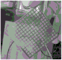
对于许多应用,最方便的是在开放的表面上执行DMF,使得围绕液滴的基质是周围的空气。图1A-图1C图示出空气基质DMF装置的一个实例。图1A示出了空气基质DMF装置100的实例。通常,空气基质DMF装置包括多个单位单元191(unit cell),所述多个单位单元191彼此相邻并且通过具有与接地电极102相对的单个致动电极106来界定;每个单位单元可以是任何合适的形状,但是通常可以具有相同的近似表面积。在图1A中,单位单元是矩形的。液滴(例如,反应液滴)适配(fit)在第一板153和第二板151(在图1A-图1C中作为顶板和底板示出)之间的气隙中。整个空气基质DMF装置可以具有任何合适的形状和厚度。图1B是穿过图1A中示出的空气基质DMF的热区的截面的放大视图,其示出了DMF设备的层(例如,形成底板的层)。通常,DMF设备(例如,底板)包括若干层,所述层可以包括在印刷电路板(PCB)材料上形成的层;这些层可以包括保护覆盖层、绝缘层和/或支撑层(例如,玻璃层、接地电极层、疏水层;疏水层、电介质层、致动电极层、PCB、热控制层等)。这些表面中的任一个可以是刚性的(例如,玻璃、PCB、聚合物材料等)。本文描述的空气基质DMF装置还包括样品储存器和试剂储存器两者,以及用于补充试剂的机构。For many applications, it is most convenient to perform the DMF on an open surface such that the matrix surrounding the droplet is the surrounding air. 1A-1C illustrate one example of an air matrix DMF device. FIG. 1A shows an example of an air-based
在图1A-图1C中示出的实例中,顶板101(在这种情况下为玻璃材料(尽管可以使用包括PCB的塑料/聚合物材料))提供支撑并且保护下面的层免受外部颗粒物的损害,以及提供一定量的绝缘用于在DMF设备中执行的反应。因此,顶板可以将液滴限制/夹(sandwich)在板之间,这与(不具有板的)开放式空气基质DMF装置相比可以增强电场。上板(在该实例中为第一板)可以包括接地电极,并且可以是透明的或半透明的;例如,第一板的基板可以由玻璃和/或透明塑料形成。然而,虽然上板是透明的,但是其可以涂覆有导电材料和/或可以包括用于DMF电路的与基板相邻并且在基板之下的接地电极(接地电极层102)。在某些情况下,接地电极是连续的涂层;可选择地,可以使用多个接地电极,例如相邻的接地电极。接地电极层之下是疏水层103。疏水层103用于减少表面的湿润,并且有助于将反应液滴保持在一个内聚单元(cohesive unit)中。In the example shown in FIGS. 1A-1C , the top plate 101 (in this case a glass material (although plastic/polymer materials including PCBs can be used)) provides support and protects the underlying layers from foreign particles damage, as well as providing a certain amount of insulation for the reactions performed in the DMF device. Thus, the top plate can confine/sandwich the droplets between the plates, which can enhance the electric field compared to an open air matrix DMF device (without plates). The upper plate (the first plate in this example) may include a ground electrode, and may be transparent or translucent; for example, the substrate of the first plate may be formed of glass and/or transparent plastic. However, although the upper plate is transparent, it may be coated with a conductive material and/or may include a ground electrode (ground electrode layer 102 ) adjacent to and below the substrate for the DMF circuit. In some cases, the ground electrode is a continuous coating; alternatively, multiple ground electrodes may be used, such as adjacent ground electrodes. Below the ground electrode layer is a
作为图1A-图1C中的下板或底板151示出的第二板可以包括界定单位单元的致动电极。在该实例中,如同第一板,面向板之间的气隙104的最外层还包括疏水层103。形成疏水层的材料在两个板上可以是相同的,或其可以是不同的疏水材料。气隙104提供了空间,在所述空间中,反应液滴初始地被包括在样品储存器中,并且被移动用于运行反应步骤或多个反应步骤以及用于保持各种试剂用于各个反应步骤。与第二板上的疏水层103相邻的是电介质层105,所述电介质层105可以增加液滴和电极之间的电容。与电介质层105相邻并且在电介质层105之下的是PCB层,所述PCB层包括致动电极(致动电极层106)。致动电极可以形成每个单位单元。致动电极可以被通电以在DMF设备中将液滴移动至不同的区域,使得各个反应步骤可以在不同条件下(例如,温度、与不同试剂组合、磁性区域、泵入口区域等)进行。支撑基板107(例如,PCB)(在图1B和图1C中)可以与致动电极层106相邻并且在致动电极层106之下,以为这些部件提供支撑和电连接,这些部件包括致动电极、连接它们的迹线(其可以是绝缘的)和/或另外的控制元件,另外的控制元件包括热调节器155(作为TEC示出)、温度传感器、光学传感器、磁体、泵等。用于控制致动电极的操作和/或控制将液滴补充至反应液滴的施加的一个或更多个控制器195可以被连接,但是与第一板153和第二板151隔开,或其可以在第二板上形成和/或通过第二板来支撑。在图1A-图1C中,第一板作为顶板示出,并且第二板是底板;该定向可以反转。还示出了溶剂(补充流体)的源或储存器197,所述溶剂(补充流体)的源或储存器197通过管道198被连接至第二板中的穿孔。The second plate, shown as the lower plate or
如提及的,气隙104提供了在其中可以执行反应步骤的空间,这提供了通过混合、加热/冷却、与试剂(酶、标记物等)组合,可以将试剂保持在其中并且可以在其中处理试剂的区域。在图1A中,气隙104包括样品储存器110和一系列试剂储存器111。样品储存器还可以包括样品加载特征,用于将初始反应液滴引入到DMF设备中。基于待被执行的反应的需要,样品加载可以从上面、从下面或从侧面来加载,并且可以是唯一的。图1A中示出的样品DMF设备包括六个样品试剂储存器,其中每个样品试剂储存器包括开口或端口用于将每种试剂引入到相应的储存器中。根据待被执行的反应,试剂储存器的数目可以是可变的。样品储存器110和试剂储存器111通过反应区流体连通。反应区112与致动电极层106电连通,其中致动电极层106位于反应区112之下。As mentioned, the air gap 104 provides a space in which reaction steps can be performed, which provides that reagents can be held and in which by mixing, heating/cooling, combining with reagents (enzymes, labels, etc.) Area where reagents are handled. In FIG. 1A , the air gap 104 includes a
致动电极106在图1A中被描绘为栅格或单位单元。在其他实例中,基于反应的需要,致动电极可以在完全不同的图案或布置中。致动电极被配置成将液滴从DMF设备的一个区域移动至另一个区域或多个区域。移动以及在某种程度上液滴的形状可以通过切换致动电极的电压来控制。一个或更多个液滴可以通过以受控制的方式将电极顺序地通电和断电,来沿着致动电极的路径移动。在示出的DMF装置的实例中,一百个致动电极(形成约一百个单位单元)与七个储存器(一个样品储存器和六个试剂储存器)连接。致动电极可以由任何合适的导电材料制成,例如铜、镍、金或其组合。The
在图1A-图1C示出的示例性设备中,DMF装置典型地被集成,使得电极(例如,致动电极和接地电极)是可以加载有样品和/或流体的相同结构的一部分。电极可以是盒的一部分,所述盒可以是可移除的。尽管盒已经被描述(参见,例如US20130134040),然而已经证明这样的盒难以使用,特别是当通过设备成像时以及当在空气基质装置中操作时。In the exemplary apparatus shown in FIGS. 1A-1C , the DMF device is typically integrated such that the electrodes (eg, the actuation electrode and the ground electrode) are part of the same structure that can be loaded with sample and/or fluid. The electrodes may be part of a cartridge, which may be removable. Although cartridges have been described (see, eg, US20130134040), such cartridges have proven difficult to use, especially when imaging through the apparatus and when operating in air-based devices.
将高度有利的是具有空气基质DMF装置,该装置包括易于使用的盒,并且可以可靠地并且便宜地制成。本文描述了可以解决这些问题的方法和装置,包括系统和设备。It would be highly advantageous to have an air matrix DMF device that includes a cartridge that is easy to use and that can be manufactured reliably and inexpensively. This document describes methods and apparatus, including systems and devices, that may address these issues.
公开内容的概述Overview of public content
本文描述了数字微流控(DMF)方法和装置(包括设备、系统、盒、DMF读取器等)。尽管本文描述的方法和装置可以特别地适于空气基质DMF装置(本文中还被称为气隙DMF装置),然而这些方法和装置可以被配置用于其他DMF装置(例如,油间隙等)。本文描述的方法和装置可以被用于操作相对较大的体积,这利用传统的DMF装置已经是可能的,部分地因为形成DMF装置的气隙的板之间的间距可以是较大的(例如,大于280微米、300微米或更大、350微米或更大、400微米或更大、500微米或更大、700微米或更大、1mm或更大等)。此外,本文描述的任何装置和方法可以被配置成包括一次性盒,所述一次性盒具有形成盒的底部的电介质层;驱动电极不必须是盒的一部分;这些装置可以适于在操作期间允许电介质(dielectric)被牢固地保持至电极,这已经被证明是非常有挑战性的,特别是当电介质层是略微柔性的时。Digital microfluidics (DMF) methods and apparatus (including devices, systems, cartridges, DMF readers, etc.) are described herein. Although the methods and devices described herein may be particularly suitable for air matrix DMF devices (also referred to herein as air gap DMF devices), the methods and devices may be configured for use with other DMF devices (eg, oil gaps, etc.). The methods and devices described herein can be used to operate relatively large volumes, which have been possible with conventional DMF devices, in part because the spacing between the plates forming the air gaps of the DMF device can be large (eg, , greater than 280 microns, 300 microns or greater, 350 microns or greater, 400 microns or greater, 500 microns or greater, 700 microns or greater, 1 mm or greater, etc.). Furthermore, any of the devices and methods described herein may be configured to include a disposable cartridge having a dielectric layer forming the bottom of the cartridge; the drive electrodes need not be part of the cartridge; these devices may be adapted to allow during operation The dielectric is held firmly to the electrodes, which has proven to be very challenging, especially when the dielectric layer is slightly flexible.
本文描述的任何方法和装置可以包括盒,在所述盒中接地电极被包括作为盒的一部分。在某些变型中,接地电极可以被形成为栅格图案,所述栅格图案形成多个单元。栅格图案可以产生透明窗口(clear window),即使当不透明的接地电极(例如,不透明或半透明的材料,比如例如包含银导电油墨的金属涂层)被用于形成接地电极时这也允许通过接地电极的可视化。栅格图案可以反映DMF装置中的驱动电极的布置,盒可以被放置到DMF装置上。例如,当接地电极跨过气隙与驱动电极相邻时,栅格图案覆盖相邻电极之间的空间。可选择地,接地电极可以由透明或足够透明的材料形成,使得它可以被成像。在某些变型中,接地电极是导电涂层。接地电极可以是电连续的(例如,电相接的),但是可以包括一个或更多个开口,例如,通过所述开口,气隙中的液滴可以被可视化。因此,在这些变型中的任一个中,盒的上板可以是透明的或足够透明的,以至少在一个或更多个区域中被可视化。Any of the methods and apparatus described herein may include a cartridge in which a ground electrode is included as part of the cartridge. In some variations, the ground electrodes may be formed in a grid pattern that forms a plurality of cells. The grid pattern can create a clear window, which allows passage through even when an opaque ground electrode (eg, an opaque or translucent material such as, for example, a metallic coating containing silver conductive ink) is used to form the ground electrode Visualization of the ground electrode. The grid pattern can reflect the arrangement of the drive electrodes in the DMF device onto which the cartridge can be placed. For example, when the ground electrode is adjacent to the driving electrode across the air gap, the grid pattern covers the space between the adjacent electrodes. Alternatively, the ground electrode may be formed of a transparent or sufficiently transparent material so that it can be imaged. In some variations, the ground electrode is a conductive coating. The ground electrode may be electrically continuous (eg, electrically connected), but may include one or more openings, eg, through which droplets in the air gap may be visualized. Thus, in any of these variations, the upper panel of the box may be transparent or sufficiently transparent to be visualized at least in one or more areas.
例如,用于数字微流控(DMF)装置的盒可以具有底部和顶部,并且可以包括:电介质材料片,所述电介质材料片具有第一侧面和第二侧面,第一侧面在盒的底部上形成暴露的底表面,其中电介质材料片的至少第二侧面包括第一疏水表面;顶板,所述顶板具有第一侧和第二侧;在顶板的第一侧上的接地电极。接地电极可以包括栅格图案,所述栅格图案形成多个开放单元。盒还可以包括:在顶板的第一侧上覆盖接地电极的第二疏水表面;以及气隙,所述气隙将第一疏水层和第二疏水层隔开,其中气隙包括大于280微米的间距。For example, a cartridge for a digital microfluidic (DMF) device may have a bottom and a top, and may include a sheet of dielectric material having a first side and a second side, the first side being on the bottom of the cartridge An exposed bottom surface is formed, wherein at least a second side of the sheet of dielectric material includes a first hydrophobic surface; a top plate having a first side and a second side; and a ground electrode on the first side of the top plate. The ground electrode may include a grid pattern forming a plurality of open cells. The cell may also include: a second hydrophobic surface covering the ground electrode on the first side of the top plate; and an air gap separating the first and second hydrophobic layers, wherein the air gap includes a spacing.
在本文描述的任何盒中,顶板可以包括在顶板的厚度内的多个空腔;这些空腔可以被封闭(例如密封)和/或填充有具有低热质量和低热导率的热绝缘材料。在某些变型中,绝缘材料包括空气。空腔可以被定位在气隙区域上面,所述气隙区域将对应于加热和/冷却区域(例如热控制区域);这些区域中的较低热质量可以允许空腔/多个空腔下方的气隙中的液滴的显著地更迅速的加热/冷却。因此,这些区域中顶板的厚度可以包括空腔;空腔底部(对应于顶板的底表面)可以小于1mm厚(例如,小于0.9mm、0.8mm、0.7mm、0.6mm、0.5mm、0.4mm、0.3mm、0.2mm、0.1mm、90微米、80微米、70微米、60微米、50微米、40微米、30微米等)。空腔底部可以优选地尽可能薄,同时为电极和顶板的底表面上的任何电介质涂层提供结构支撑。空腔上表面可以大体上比空腔底表面更厚(例如,1.5倍、2倍、3倍、4倍、5倍等)。In any of the boxes described herein, the top plate can include a plurality of cavities within the thickness of the top plate; these cavities can be enclosed (eg, sealed) and/or filled with thermally insulating material having low thermal mass and low thermal conductivity. In some variations, the insulating material includes air. Cavities may be positioned over air gap regions that would correspond to heating and/or cooling regions (eg, thermal control regions); lower thermal mass in these regions may allow Significantly more rapid heating/cooling of droplets in the air gap. Thus, the thickness of the top plate in these regions may include the cavity; the bottom of the cavity (corresponding to the bottom surface of the top plate) may be less than 1 mm thick (eg, less than 0.9mm, 0.8mm, 0.7mm, 0.6mm, 0.5mm, 0.4mm, 0.3mm, 0.2mm, 0.1mm, 90 microns, 80 microns, 70 microns, 60 microns, 50 microns, 40 microns, 30 microns, etc.). The cavity bottom may preferably be as thin as possible while providing structural support for the electrodes and any dielectric coatings on the bottom surface of the top plate. The cavity upper surface may be substantially thicker (eg, 1.5 times, 2 times, 3 times, 4 times, 5 times, etc.) than the cavity bottom surface.
形成底表面的电介质材料可以被制成为疏水的(例如,通过涂覆,包括浸涂等;用疏水材料浸渍等)和/或其本身可以是疏水的。例如,底表面(例如,盒的底表面)可以由膜形成,所述膜是电介质材料和疏水材料两者。例如,底表面可以是特氟龙(Teflon)膜(其可以包括粘合剂或粘合部分,例如特氟龙带),所述特氟龙膜既是疏水的并且又充当电介质。其他膜可包括塑料石蜡膜)(plastic paraffin film)(例如,“Parafilm”,例如PARAFILM M)。然而,特别地,能够承受高温(例如,100摄氏度及以上)的膜(例如特氟龙膜)是优选的。The dielectric material forming the bottom surface can be made hydrophobic (eg, by coating, including dip coating, etc.; impregnating with a hydrophobic material, etc.) and/or can be hydrophobic itself. For example, the bottom surface (eg, the bottom surface of the cell) may be formed of a film that is both a dielectric material and a hydrophobic material. For example, the bottom surface can be a Teflon film (which can include an adhesive or adhesive portion, such as a Teflon tape) that is both hydrophobic and acts as a dielectric. Other films may include plastic paraffin films (eg, "Parafilm" such as PARAFILM M). In particular, however, membranes (eg, Teflon membranes) capable of withstanding high temperatures (eg, 100 degrees Celsius and above) are preferred.
用于数字微流控(DMF)装置的盒通常可以包括底部和顶部,并且可以包括:电介质材料片,所述电介质材料片具有第一侧面和第二侧面,第一侧面在盒的底部上形成暴露的底表面;在电介质材料片的第二侧面上的第一疏水层;顶板,所述顶板具有第一侧和第二侧;在顶板的第一侧上的接地电极,其中接地电极包括形成多个开放单元的栅格图案;在顶板的第一侧上覆盖接地电极的第二疏水层;以及气隙,所述气隙将第一疏水层和第二疏水层隔开,其中气隙包括大于280微米(例如,大于300微米、大于400微米等)的间距。A cassette for a digital microfluidic (DMF) device can generally include a bottom and a top, and can include a sheet of dielectric material having a first side and a second side, the first side being formed on the bottom of the cassette an exposed bottom surface; a first hydrophobic layer on the second side of the sheet of dielectric material; a top plate having a first side and a second side; a ground electrode on the first side of the top plate, wherein the ground electrode comprises forming a grid pattern of multiple open cells; a second hydrophobic layer covering the ground electrode on the first side of the top plate; and an air gap separating the first and second hydrophobic layers, wherein the air gap includes Pitches greater than 280 microns (eg, greater than 300 microns, greater than 400 microns, etc.).
术语“盒”可以指的是形成气隙的容器,并且可以被插入到DMF读取/驱动装置中。盒可以是一次性的(例如,单次使用或有限使用)。盒可以被配置成允许气隙中的流体(液滴)的可视化。栅格图案可以特别地用于允许可视化,同时仍然提供对驱动电极的合适的接地参考。整个栅格可以被电耦合以形成单个返回(return)(接地)电极,或多个接地电极可以(经由单独的和/或相邻的栅格)被定位在顶板上。The term "cartridge" may refer to a container that forms an air gap and may be inserted into a DMF read/drive device. Cartridges can be disposable (eg, single use or limited use). The cassette may be configured to allow visualization of fluid (droplets) in the air gap. A grid pattern can be used in particular to allow visualization while still providing a suitable ground reference to the drive electrodes. The entire grid can be electrically coupled to form a single return (ground) electrode, or multiple ground electrodes can be positioned on the top plate (via separate and/or adjacent grids).
如提及的,接地电极的栅格图案由不透明材料形成。As mentioned, the grid pattern of the ground electrode is formed of an opaque material.
如本文使用的,术语“栅格”可以指的是任何合适的形状和大小的重复开放单元(“窗口”)的图案,其中形成开放单元的边界通过集成的(并且电连续的)材料(例如导电油墨、金属涂层等)形成。如本文使用的,栅格不限于彼此交叉以形成一系列正方形或矩形的线的网络;栅格图案可以通过在形成接地电极的导电材料的另外连续平面中形成开口来形成。As used herein, the term "grid" may refer to a pattern of repeating open cells ("windows") of any suitable shape and size, wherein the boundaries forming the open cells are formed by an integrated (and electrically continuous) material such as conductive inks, metal coatings, etc.) are formed. As used herein, a grid is not limited to a network of lines crossing each other to form a series of squares or rectangles; a grid pattern may be formed by forming openings in an otherwise continuous plane of conductive material forming the ground electrode.
因此,通常,接地电极的栅格图案可以由导电油墨形成。例如,接地电极的栅格图案可以由银纳米颗粒形成。栅格图案可以被印刷、丝网印刷(screened)、喷涂或以其他方式分层堆积(layered)到顶板上。Therefore, generally, the grid pattern of the ground electrode may be formed of conductive ink. For example, the grid pattern of the ground electrode may be formed of silver nanoparticles. The grid pattern can be printed, screened, sprayed or otherwise layered onto the top plate.
通常,形成栅格图案的开放单元之间的边界可以具有最小宽度。例如,开放单元之间的栅格图案的最小宽度可以是50微米或更大(例如,0.1mm或更大、0.2mm或更大、0.3mm或更大、0.4mm或更大、0.5mm或更大、0.6mm或更大、0.7mm或更大、0.8mm或更大、0.9mm或更大、1mm或更大等)。如提及的,通过栅格图案形成的开放单元(例如,“窗口”)可以是任何形状,包括四边形形状(例如,正方形、矩形等)或椭圆形形状(例如卵形、圆形等)和/或其他形状(+形状、H形状等)。Generally, the boundaries between the open cells forming the grid pattern may have a minimum width. For example, the minimum width of the grid pattern between open cells can be 50 microns or greater (eg, 0.1 mm or greater, 0.2 mm or greater, 0.3 mm or greater, 0.4 mm or greater, 0.5 mm or greater, or larger, 0.6mm or more, 0.7mm or more, 0.8mm or more, 0.9mm or more, 1mm or more, etc.). As mentioned, the open cells (eg, "windows") formed by the grid pattern can be of any shape, including quadrilateral (eg, square, rectangular, etc.) or elliptical (eg, oval, circular, etc.) and / or other shapes (+ shape, H shape, etc.).
通常,接地电极的栅格图案可以在顶板的大部分(和/或盒的大部分)上面延伸。例如,接地电极的栅格图案可以在顶板的第一侧的50%或更大(例如,55%或更大、60%或更大、65%或更大、70%或更大、80%或更大、90%或更大等)上面延伸。Typically, the grid pattern of ground electrodes may extend over most of the top plate (and/or most of the box). For example, the grid pattern of ground electrodes may be 50% or more of the first side of the top plate (eg, 55% or more, 60% or more, 65% or more, 70% or more, 80% or greater, 90% or greater, etc.).
在本文描述的任何盒中,电介质材料片可以是柔性的。该柔性可以有助于将电介质固定至驱动电极,以确保电介质和驱动电极之间的完全接触。典型地,电介质材料片可以是足够依从性的(compliant),使得其可以在相对低的力(例如,50kPa的压力或更大)下弯曲或挠曲。电介质片可以是任何合适的厚度;例如,片可以小于30微米厚(例如,小于20微米厚等)。In any of the cartridges described herein, the sheet of dielectric material may be flexible. This flexibility can help secure the dielectric to the drive electrodes to ensure complete contact between the dielectric and drive electrodes. Typically, the sheet of dielectric material may be sufficiently compliant so that it can bend or flex under relatively low forces (eg, a pressure of 50 kPa or more). The dielectric sheet may be of any suitable thickness; for example, the sheet may be less than 30 microns thick (eg, less than 20 microns thick, etc.).
如将在下文更详细地描述的,这些装置中的任一个可以包括在顶板的第二侧中形成的微流控通道,其中微流控通道沿着顶板的第二侧和在微流控通道和气隙之间的至少一个开口延伸。As will be described in more detail below, any of these devices may include a microfluidic channel formed in the second side of the top plate, wherein the microfluidic channel is along the second side of the top plate and in the microfluidic channel and at least one opening extending between the air gap.
顶板可以由任何合适的材料形成,特别地包括透明材料(clear material)或透明材料(transparent material)(例如丙烯酸等)。The top plate may be formed of any suitable material, including in particular a clear material or a transparent material (eg, acrylic, etc.).
例如,用于数字微流控(DMF)装置的盒可以包括:柔性电介质材料片,所述柔性电介质材料片具有第一侧面和第二侧面,第一侧面在盒的底部上形成暴露的底表面;在电介质材料片的第二侧面上的第一疏水层;顶板,所述顶板具有第一侧和第二侧;在顶板的第一侧上的接地电极,其中接地电极包括沿着顶板的第一侧形成多个开放单元的由不透明材料形成的栅格图案;在顶板的第一侧上覆盖接地电极的第二疏水层;以及气隙,所述气隙将第一疏水层和第二疏水层隔开,其中气隙包括大于280微米(例如,大于300微米或更大、400微米或更大等)的间距。典型地,盒具有底部和顶部。For example, a cassette for a digital microfluidic (DMF) device may include a sheet of flexible dielectric material having a first side and a second side, the first side forming an exposed bottom surface on the bottom of the cassette a first hydrophobic layer on the second side of the sheet of dielectric material; a top plate having a first side and a second side; a ground electrode on the first side of the top plate, wherein the ground electrode comprises a first side along the top plate a grid pattern formed of an opaque material with a plurality of open cells formed on one side; a second hydrophobic layer covering the ground electrode on the first side of the top plate; and an air gap connecting the first hydrophobic layer and the second hydrophobic layer The layers are separated, wherein the air gap includes a pitch greater than 280 microns (eg, greater than 300 microns or greater, 400 microns or greater, etc.). Typically, a box has a bottom and a top.
如提及的,本文还描述了盒,在盒中微流控通道被集成到DMF部件中,特别地DMF部件包括DMF装置的顶板。申请人已经发现,将一个或更多个微流控通道集成到顶板中可以允许盒更紧凑,以及允许对在气隙中过程的更高度的控制和操纵,该过程另外通过将DMF系统电润湿(electrowetting)来控制。As mentioned, cassettes are also described herein in which microfluidic channels are integrated into DMF components, in particular the DMF components comprising the top plate of the DMF device. Applicants have discovered that integrating one or more microfluidic channels into the top plate can allow for a more compact cassette, as well as a higher degree of control and manipulation of the process in the air gap, which is additionally achieved by electrolyzing the DMF system Wetting (electrowetting) to control.
例如,用于数字微流控(DMF)装置的盒(该盒具有底部和顶部)可以包括:电介质材料片,所述电介质材料片具有第一侧面和第二侧面,第一侧面在盒的底部上形成暴露的底表面;在电介质材料片的第二侧面上的第一疏水层;顶板,所述顶板具有第一侧和第二侧;在顶板的第一侧上的接地电极;在顶板的第一侧上覆盖接地电极的第二疏水层;气隙,所述气隙将第一疏水层和第二疏水层隔开;在顶板的第二侧中形成的微流控通道,其中微流控通道沿着顶板的第二侧延伸;在微流控通道和气隙之间的开口;以及覆盖微流控通道的盖,其中盖包括用于进入微流控通道的一个或更多个接入端口(access port)。For example, a cartridge for a digital microfluidic (DMF) device (the cartridge having a bottom and a top) may include a sheet of dielectric material having a first side and a second side, the first side being at the bottom of the cartridge an exposed bottom surface formed thereon; a first hydrophobic layer on a second side of the sheet of dielectric material; a top plate having a first side and a second side; a ground electrode on the first side of the top plate; a second hydrophobic layer covering the ground electrode on the first side; an air gap separating the first and second hydrophobic layers; a microfluidic channel formed in the second side of the top plate in which the microfluidic a control channel extending along the second side of the top plate; an opening between the microfluidic channel and the air gap; and a cover covering the microfluidic channel, wherein the cover includes one or more accesses for entering the microfluidic channel port (access port).
如提及的,电介质材料片可以是柔性的,并且可以形成盒的最底表面(bottom-most surface)。片通常可以是平的(平坦的),尽管其可以是柔性的。外表面可以用可移除(例如,剥离)的盖保护。电介质性质可以是通常与DMF(并且特别地空气基质DMF)装置一致的性质。电介质可以在内侧(第二侧)上涂覆有第一疏水层。疏水层可以是相对惰性(例如,与在气隙中移动的含水液滴不反应)的疏水材料的涂层。As mentioned, the sheet of dielectric material may be flexible and may form the bottom-most surface of the case. The sheet may generally be flat (flat), although it may be flexible. The outer surface may be protected with a removable (eg, peel-off) cover. The dielectric properties may be properties generally consistent with DMF (and particularly air-based DMF) devices. The dielectric may be coated with a first hydrophobic layer on the inner side (second side). The hydrophobic layer may be a coating of a hydrophobic material that is relatively inert (eg, does not react with aqueous droplets moving in the air gap).
顶板可以是平坦的,并且可以是与底部电介质材料共同延伸的(或比底部电介质材料更大)。顶板可以是任何合适的厚度,并且特别地可以是足够厚的,使得微流控通道可以被雕刻到顶板的第二侧中。如上文提及的,接地电极可以在顶板的第一侧的全部或某些上形成,并且第二疏水层可以被涂覆在接地电极和/或顶板上面(特别地在通过接地板(ground plate)的开放窗口将顶板暴露的地方)。在这些实例中的任一个中,电极涂层的厚度可以是最小的,使得电极可以被认为与顶板的顶板底(第一)侧齐平。The top plate can be flat and can be coextensive with (or larger than) the bottom dielectric material. The top plate can be of any suitable thickness, and in particular can be thick enough that microfluidic channels can be carved into the second side of the top plate. As mentioned above, a ground electrode may be formed on all or some of the first side of the top plate, and a second hydrophobic layer may be coated over the ground electrode and/or the top plate (in particular through the ground plate ) where the open window will expose the top panel). In either of these examples, the thickness of the electrode coating can be minimal such that the electrodes can be considered flush with the top plate bottom (first) side of the top plate.
在本文描述的任何装置和方法中,与传统的DMF气隙系统相比,隔开第一疏水层和第二疏水层(例如,在电介质和顶板之间)的气隙可以是相对大的(例如>280微米、400微米或更大、500微米或更大、1mm或更大等)。In any of the devices and methods described herein, the air gap separating the first and second hydrophobic layers (eg, between the dielectric and the top plate) can be relatively large (eg, between the dielectric and the top plate) compared to conventional DMF air gap systems ( For example >280 microns, 400 microns or more, 500 microns or more, 1 mm or more, etc.).
在顶板的第二侧中形成的微流控通道典型地沿着顶板的第二侧延伸穿过顶板,并且微流控通道和气隙之间的接入开口(access opening)可以在微流控通道和气隙之间形成进入顶板。本文描述的任何装置还可以包括覆盖微流控通道的盖。盖可以由任何合适的材料制成,所述材料包括丙烯酸。盖可以包括进入微流控通道和/或进入气隙的一个或更多个端口或开口。The microfluidic channel formed in the second side of the top plate typically extends through the top plate along the second side of the top plate, and an access opening between the microfluidic channel and the air gap may be in the microfluidic channel and an air gap is formed into the top plate. Any of the devices described herein can also include a cover covering the microfluidic channel. The cover can be made of any suitable material, including acrylic. The cover may include one or more ports or openings into the microfluidic channel and/or into the air gap.
微流控通道可以被配置成包含任何合适量的流体,这对于混合、添加、移除或以其他方式与气隙中的液滴相互作用是有用的。例如,微流控通道可以被配置成将0.2毫升或更大(例如,0.3ml或更大、0.4ml或更大、0.5ml或更大、0.6ml或更大、0.7ml或更大、0.8ml或更大、0.9ml或更大、1ml或更大、1.5ml或更大、2ml或更大、3ml或更大、4ml或更大、5ml或更大、6ml或更大、7ml或更大、8ml或更大、9ml或更大、10ml或更大等)的流体保持在微流控通道中。微流控通道可以连接至一个或更多个储存器(例如,废物储存器、储物储存器(storagereservoir)等)和/或可以连接至一个或更多个另外的微流控通道。Microfluidic channels can be configured to contain any suitable amount of fluid useful for mixing, adding, removing, or otherwise interacting with droplets in the air gap. For example, the microfluidic channel can be configured to convert 0.2 ml or more (eg, 0.3 ml or more, 0.4 ml or more, 0.5 ml or more, 0.6 ml or more, 0.7 ml or more, 0.8 ml or more ml or more, 0.9ml or more, 1ml or more, 1.5ml or more, 2ml or more, 3ml or more, 4ml or more, 5ml or more, 6ml or more, 7ml or more large, 8 ml or more, 9 ml or more, 10 ml or more, etc.) of fluid is held in the microfluidic channel. The microfluidic channel can be connected to one or more reservoirs (eg, waste reservoir, storage reservoir, etc.) and/or can be connected to one or more additional microfluidic channels.
例如,微流控通道可以包括第一微流控通道,并且微流控通道和气隙之间的开口可以包括第一开口;该装置还可以包括在顶板的第二侧中形成的第二微流控通道和在第二微流控通道和气隙之间的第二开口,其中第二微流控通道沿着顶板的第二侧延伸,其中第一开口和第二开口彼此相邻。第一开口和第二开口可以相距最小距离,这可以允许在具有最小尺寸的气隙中形成“桥接液滴(bridging droplet)”。例如,第一开口和第二开口在顶板的表面上可以在彼此的约2cm内(例如,在彼此的约1cm内、在彼此的约9mm内、在彼此的约8mm内、在彼此的约7mm内、在彼此的约6mm内、在彼此的约5mm内、在彼此的约4mm内、在彼此的约3mm内、在彼此的约2mm内、在彼此的约1mm内等)。For example, the microfluidic channel can comprise a first microfluidic channel, and the opening between the microfluidic channel and the air gap can comprise the first opening; the device can also comprise a second microfluidic formed in the second side of the top plate A control channel and a second opening between the second microfluidic channel and the air gap, wherein the second microfluidic channel extends along the second side of the top plate, wherein the first opening and the second opening are adjacent to each other. The first opening and the second opening may be separated by a minimum distance, which may allow the formation of "bridging droplets" in the air gap with the minimum size. For example, the first opening and the second opening may be within about 2 cm of each other on the surface of the top plate (eg, within about 1 cm of each other, within about 9 mm of each other, within about 8 mm of each other, within about 7 mm of each other within about 6 mm of each other, within about 5 mm of each other, within about 4 mm of each other, within about 3 mm of each other, within about 2 mm of each other, within about 1 mm of each other, etc.).
这些盒中的任一个还可以包括从盒的顶部至气隙的窗口,通过所述窗口,气隙是可见的。这可以允许成像到气隙中。该成像可以被用于检测输出(例如,反应输出,例如结合、比色测定法、RT-PCR等)。窗口可以是任何合适的尺寸;例如,窗口可以形成盒的顶部的2%到50%之间。窗口可以在盒的一侧和/或在盒的一端。可以使用多个成像窗口。Any of these boxes may also include a window from the top of the box to the air gap through which the air gap is visible. This can allow imaging into the air gap. This imaging can be used to detect outputs (eg, reaction outputs such as binding, colorimetric assays, RT-PCR, etc.). The window may be of any suitable size; for example, the window may form between 2% and 50% of the top of the box. The window can be on one side of the box and/or at one end of the box. Multiple imaging windows can be used.
如提及的,盒的底部通过电介质材料片的第一侧面形成。盒的顶部可以包括进入气隙的多个开口。As mentioned, the bottom of the box is formed by the first side of the sheet of dielectric material. The top of the box may include a number of openings into the air gap.
通常,盒可以包括在顶板的第二侧上的一个或更多个试剂储存器。例如,在储存器中或气隙内,盒可以包括一种或更多种试剂,特别地包括冻干的(例如,“冷冻干燥的”)试剂。例如,盒可以包括在顶板的第二侧上的一个或更多个冷冻干燥的试剂储存器。Typically, the cartridge may include one or more reagent reservoirs on the second side of the top plate. For example, in a reservoir or within an air gap, a cartridge can include one or more reagents, particularly lyophilized (eg, "freeze-dried") reagents. For example, the cartridge may include one or more freeze-dried reagent reservoirs on the second side of the top plate.
例如,用于数字微流控(DMF)装置的盒(具有底部和顶部)可以包括:电介质材料片,所述电介质材料片具有第一侧面和第二侧面,第一侧面在盒的底部上形成暴露的底表面;在电介质材料片的第二侧面上的第一疏水层;顶板,所述顶板具有第一侧和第二侧;在顶板的第一侧上的接地电极;在顶板的第一侧上覆盖接地电极的第二疏水层;气隙,所述气隙将第一疏水层和第二疏水层隔开,其中气隙包括大于500微米的间距;第一微流控通道和第二微流控通道,其中第一微流控通道和第二微流控通道在顶板的第二侧中形成,其中第一微流控通道和第二微流控通道沿着顶板的第二侧延伸;在第一微流控通道和气隙之间的第一开口以及在第二微流控通道和气隙之间的第二开口,其中第一开口和第二开口在约2cm内彼此相邻;以及覆盖微流控通道的盖,其中盖包括用于进入微流控通道的一个或更多个接入端口。For example, a cartridge (having a bottom and a top) for a digital microfluidic (DMF) device may include a sheet of dielectric material having a first side and a second side, the first side being formed on the bottom of the cartridge an exposed bottom surface; a first hydrophobic layer on the second side of the sheet of dielectric material; a top plate having a first side and a second side; a ground electrode on the first side of the top plate; a second hydrophobic layer covering the ground electrode on the side; an air gap separating the first and second hydrophobic layers, wherein the air gap includes a spacing greater than 500 microns; the first microfluidic channel and the second hydrophobic layer a microfluidic channel, wherein the first microfluidic channel and the second microfluidic channel are formed in the second side of the top plate, wherein the first microfluidic channel and the second microfluidic channel extend along the second side of the top plate a first opening between the first microfluidic channel and the air gap and a second opening between the second microfluidic channel and the air gap, wherein the first opening and the second opening are adjacent to each other within about 2 cm; and A cover covering the microfluidic channel, wherein the cover includes one or more access ports for accessing the microfluidic channel.
本文还描述了用于与本文描述的任何盒一起使用的DMF读取器装置。例如,DMF读取器装置(设备)可以被配置成跨过盒的电介质底表面施加真空,使得电极与形成每个单位单元形式(unit cells form)的电介质均匀地紧密接触,这使流体的液滴在气隙中移动。本申请人已经令人惊讶地发现,将电介质材料简单地粘合固定至电极是不够的,因为其导致不相等的接触和移动液滴所需功率的变化,以及液滴移动、控制和一致性的低效率。此外,即使与粘合剂结合,真空的使用也具有类似的问题,特别是当电介质是柔性的时。本文描述了使用它们的装置和方法,其中真空被用于通过驱动电极本身中的多个开口或围绕/紧密相邻驱动电极来固定盒的电介质底部。在其中通过全部或某些驱动电极(例如,在基座表面(seating surface)上,例如在角落(corner)处以图案间隔开)施加真空的变型中,电介质以均匀的方式一致地被保持在驱动电极上,即使当使用对于真空的相对低的负压力时。该配置还可以允许通过包括在盒-保持表面(cartridge-holding surface)(盒被保持在盒-保持表面上)上的突起,在盒中形成隔断(partition)或屏障。Also described herein are DMF reader devices for use with any of the cartridges described herein. For example, a DMF reader device (apparatus) can be configured to apply a vacuum across the dielectric bottom surface of the cartridge so that the electrodes are in uniform intimate contact with the dielectric forming each unit cells form, which allows the fluidity of the fluid The drop moves in the air gap. The applicant has surprisingly found that simply adhesively securing the dielectric material to the electrodes is not sufficient as it results in unequal contact and variation in the power required to move the droplet, as well as droplet movement, control and consistency of inefficiency. Furthermore, the use of vacuum, even in combination with adhesives, has similar problems, especially when the dielectric is flexible. Described herein are devices and methods of using them in which a vacuum is used to secure the dielectric bottom of the cartridge through multiple openings in the drive electrodes themselves or around/closely adjacent to the drive electrodes. In variants in which a vacuum is applied through all or some of the drive electrodes (eg, on the seating surface, eg spaced in a pattern at the corners), the dielectric is consistently held in the drive electrodes in a uniform manner electrodes, even when using relatively low negative pressures for vacuum. This configuration may also allow partitions or barriers to be formed in the cartridge by including protrusions on the cartridge-holding surface on which the cartridge is held.
例如,本文描述了数字微流控(DMF)读取器设备,所述数字微流控读取器装置被配置成与一次性盒一起操作,所述一次性盒具有底部电介质表面、具有接地电极的顶板以及底部电介质和顶板之间的气隙,该设备包括:基座表面,所述基座表面用于安置一次性盒;在基座表面上的多个驱动电极,其中每个驱动电极包括穿过其中的开口;真空泵,用于将真空施加至真空端口;以及控件,所述控件用于施加能量以顺序地激活和去激活(de-activate)一个或更多个选择的驱动电极,以在盒的气隙中沿着气隙中的期望路径移动液滴,其中DMF读取器被配置成当一次性盒被放置在基座表面上时将真空施加至真空歧管,以将每个驱动电极固定至一次性盒的底部电介质。For example, described herein is a digital microfluidic (DMF) reader device configured to operate with a disposable cartridge having a bottom dielectric surface, having a ground electrode A top plate and an air gap between the bottom dielectric and the top plate, the device includes: a base surface for seating a disposable cartridge; a plurality of drive electrodes on the base surface, wherein each drive electrode includes an opening therethrough; a vacuum pump for applying vacuum to the vacuum port; and a control for applying energy to sequentially activate and de-activate one or more selected drive electrodes to The droplets are moved along a desired path in the air gap of the cartridge, wherein the DMF reader is configured to apply a vacuum to the vacuum manifold when the disposable cartridge is placed on the base surface to pump each The drive electrodes are affixed to the bottom dielectric of the disposable cartridge.
在某些变型中,该装置包括真空歧管,所述真空歧管将真空泵耦合至多个真空端口用于施加真空。In some variations, the device includes a vacuum manifold that couples a vacuum pump to a plurality of vacuum ports for applying vacuum.
本文描述的DMF读取器设备可以被配置成与本文描述的任何盒一起操作,并且可以适于与这样的盒一起使用。然而,应当理解,盒不是DMF读取器装置的必要部分。通常,这些装置可以与盒(例如,可重复使用盒或一次性盒)一起操作,所述盒具有底部电介质表面、具有接地电极的顶板以及底部电介质和顶板之间的间隙(例如,典型地但不一定是气隙)。The DMF reader devices described herein may be configured to operate with, and may be adapted for use with, any of the cartridges described herein. However, it should be understood that the cartridge is not an essential part of the DMF reader device. Typically, these devices can be operated with a cartridge (eg, a reusable or disposable cartridge) having a bottom dielectric surface, a top plate with a ground electrode, and a gap between the bottom dielectric and the top plate (eg, typically but not necessarily an air gap).
DMF装置通常还可以包括基座表面用于安置一次性盒。基座表面可以包括:驱动电极,所述驱动电极可以与基座表面齐平或大体上齐平;和/或任何突起,所述突起可以用于通过在间隙区域中将电介质可预测地变形,在盒的间隙区域(例如,气隙)中形成隔断。基座表面上的多个驱动电极可以在基座表面上形成或被铣削到基座表面中。例如,基座表面可以是基板,例如印刷电路板(例如,电绝缘表面),驱动电极被附接到基板上或在基板上形成。The DMF device may also typically include a base surface for seating the disposable cartridge. The base surface may include: drive electrodes, which may be flush or substantially flush with the base surface; and/or any protrusions that may be used to predictably deform the dielectric in the gap region, The partitions are formed in the interstitial regions of the box (eg, air gaps). The plurality of drive electrodes on the base surface may be formed on the base surface or milled into the base surface. For example, the base surface may be a substrate, such as a printed circuit board (eg, an electrically insulating surface), to which the drive electrodes are attached or formed.
通常,如上文提及的,电极阵列中的驱动电极的全部或大部分(例如,>50%、>60%、>70%、>80%、>90%、>95%等)可以包括穿过驱动电极并且连接至真空源的开口。真空源可以是真空歧管,所述真空歧管将穿过驱动电极的这些开口连接至真空的源,例如作为装置的一部分的真空泵,或连接(例如,壁真空)至装置的单独的真空泵。穿过电极的开口可以是相同的大小,并且它们可以位于驱动电极上的任何地方/穿过驱动电极。例如,它们可以穿过驱动电极的中心,和/或穿过驱动电极的边缘区域等。开口可以是任何形状(例如,圆形、卵形、正方形等)。在某些变型中,开口的大小可以是直径约1mm(例如,直径1.2mm、直径1.1mm、直径1.0mm、直径0.9mm、直径0.8mm等)。Typically, as mentioned above, all or a majority (eg, >50%, >60%, >70%, >80%, >90%, >95%, etc.) of the drive electrodes in the electrode array may comprise Overdrive the electrode and connect to the opening of the vacuum source. The vacuum source may be a vacuum manifold connecting these openings through the drive electrodes to a source of vacuum, such as a vacuum pump that is part of the device, or a separate vacuum pump connected (eg, wall vacuum) to the device. The openings through the electrodes can be the same size and they can be anywhere on/through the drive electrodes. For example, they may pass through the center of the drive electrode, and/or through the edge regions of the drive electrode, and the like. The openings can be of any shape (eg, circular, oval, square, etc.). In some variations, the size of the opening may be about 1 mm in diameter (eg, 1.2 mm in diameter, 1.1 mm in diameter, 1.0 mm in diameter, 0.9 mm in diameter, 0.8 mm in diameter, etc.).
典型地,真空歧管可以被耦合至多个真空端口和/或可以包括多个真空端口,每个真空端口耦合至驱动电极中的开口中的一个(或在某些变型中,多于一个)。真空歧管可以位于基座表面之下。例如,真空歧管可以是基座表面之下的连接至驱动电极中的开口的管道或其他通道。Typically, the vacuum manifold may be coupled to and/or may include multiple vacuum ports, each vacuum port being coupled to one (or in some variations, more than one) of the openings in the drive electrodes. The vacuum manifold may be located below the surface of the base. For example, the vacuum manifold may be a conduit or other channel below the surface of the susceptor that connects to openings in the drive electrodes.
本文描述的DMF装置典型地包括控制器用于协调和驱动电极。该控制器可以包括一个或更多个处理器、存储器和对于操作该设备必要的或有用的任何其他电路,所述操作包括协调能量的施加以激活/停用(inactivate)驱动电极、用于真空控制和/或微流控制的泵、一个或更多个阀(例如,用于微流控制、真空控制)、温度控制装置(例如,电阻加热器、珀尔帖(Peltier)冷却等)、马达(例如,用于驱动打开和关闭设备门、光学器件等)、一个或更多个显示器等。The DMF devices described herein typically include a controller for coordinating and driving the electrodes. The controller may include one or more processors, memory, and any other circuitry necessary or useful for operating the device, including coordinating the application of energy to activate/inactivate drive electrodes, for vacuuming Controlled and/or microfluidic controlled pumps, one or more valves (eg, for microfluidic control, vacuum control), temperature control devices (eg, resistive heaters, Peltier cooling, etc.), motors (eg, to drive opening and closing of device doors, optics, etc.), one or more displays, and the like.
如提及的,这些设备中的任一个可以包括从基座表面延伸的一个或更多个突起,其中一个或更多个突起被配置成当通过驱动电极中的开口施加真空时,在盒的空气中形成隔断。As mentioned, any of these devices may include one or more protrusions extending from the surface of the base, wherein the one or more protrusions are configured to, when a vacuum is applied through an opening in the drive electrode, at the bottom of the cartridge A partition is formed in the air.
这些装置中的任一个可以包括光学读取器,所述光学读取器被配置成检测来自基座表面上安置的盒的光学信号。光学读取器可以是可移动的或固定的。光学读取器可以被用于检测(例如,感测)进料或由于液滴中的一种或更多种相互作用(例如,结合、酶促反应等)产生的变化。光学读取器可以被配置成检测来自基座表面上安置的盒的光学信号。因此,光学传感器可以提供对来自装置的读出的检测。这些设备中的任一个可以包括一个或更多个马达,例如,所述马达被配置成移动光学读取器。Any of these devices may include an optical reader configured to detect optical signals from cassettes disposed on the surface of the base. Optical readers can be movable or fixed. Optical readers can be used to detect (eg, sense) the feed or changes due to one or more interactions in the droplet (eg, binding, enzymatic reactions, etc.). The optical reader may be configured to detect optical signals from cassettes disposed on the surface of the base. Thus, the optical sensor can provide detection of readouts from the device. Any of these devices may include one or more motors, eg, configured to move the optical reader.
该装置还可以包括一个或更多个温度传感器(例如热敏电阻器等)。例如,该设备可以包括耦合至基座表面的一个或更多个温度传感器。在某些变型中,热敏电阻器可以从基座表面突出,并且在盒的气隙中形成屏障或室(chamber)。可选择地或另外,一个或更多个温度传感器可以在基座表面的基板中,并且例如经由导热材料(例如铜)与基座表面热接触。The device may also include one or more temperature sensors (eg, thermistors, etc.). For example, the device may include one or more temperature sensors coupled to the surface of the base. In some variations, the thermistor may protrude from the base surface and form a barrier or chamber in the air gap of the cartridge. Alternatively or additionally, one or more temperature sensors may be in the substrate of the susceptor surface and be in thermal contact with the susceptor surface, eg, via a thermally conductive material (eg, copper).
如提及的,本文描述的设备可以包括一个或更多个加热器,特别地包括电阻加热器。例如,该设备可以包括在驱动电极中的至少某些下面(或覆盖驱动电极的至少某些)的电阻加热器;这可以允许装置的温度调节的子区域。整个驱动电极表面还也可以(例如,通过冷却流体的循环)被冷却至略微低于室温(例如,在15摄氏度和25摄氏度之间、在15摄氏度和22摄氏度之间、在15摄氏度和20摄氏度之间、在15摄氏度和18摄氏度之间等)。As mentioned, the devices described herein may include one or more heaters, particularly resistive heaters. For example, the apparatus may include resistive heaters under (or overlying) at least some of the drive electrodes; this may allow for temperature-regulated sub-regions of the device. The entire drive electrode surface may also be cooled (eg, by circulation of a cooling fluid) to slightly below room temperature (eg, between 15 and 25 degrees Celsius, between 15 and 22 degrees Celsius, between 15 and 20 degrees Celsius between 15°C and 18°C, etc.).
该装置还可以包括在驱动电极中的一个或更多个之上或之下的一个或更多个磁体,所述磁体被配置成被激活以施加磁场。因此,磁珠可以用于结合材料或DMF装置中的其他反应,并且磁珠可以被选择性地保持在设备的一个或更多个区域内。例如,可以使用一个或更多个钕磁体,例如,通过将磁体移动更接近或更远离盒以将磁性颗粒保持在适当位置(例如,将磁体向上移向电极3mm、4mm、5mm、6mm、7mm、8mm等)。电磁体可以被选择性地激活或去激活以保持/释放磁性颗粒。The device may also include one or more magnets above or below one or more of the drive electrodes, the magnets configured to be activated to apply a magnetic field. Thus, the magnetic beads can be used for binding materials or other reactions in the DMF device, and the magnetic beads can be selectively retained within one or more regions of the device. For example, one or more neodymium magnets can be used, for example, by moving the magnets closer or further away from the cartridge to hold the magnetic particles in place (eg, moving the magnets up toward the electrodes 3mm, 4mm, 5mm, 6mm, 7mm , 8mm, etc.). Electromagnets can be selectively activated or deactivated to hold/release magnetic particles.
本文描述的任何装置还可以包括在驱动电极中的至少某些驱动电极的下面的一个或更多个珀尔帖冷却器,所述帕尔贴冷却器被配置成冷却至10摄氏度或更少(例如,5摄氏度或更少、7摄氏度或更少、11摄氏度或更少、12摄氏度或更少、15摄氏度或更少、20摄氏度或更少等)。Any of the devices described herein may also include one or more Peltier coolers below at least some of the drive electrodes, the Peltier coolers configured to cool to 10 degrees Celsius or less ( For example, 5 degrees Celsius or less, 7 degrees Celsius or less, 11 degrees Celsius or less, 12 degrees Celsius or less, 15 degrees Celsius or less, 20 degrees Celsius or less, etc.).
除了基座表面之外,这些DMF读取器装置中的任一个还可以包括一个或更多个盒托盘,盒可以被加载到所述盒托盘中,使得盒可以自动地移动到装置内的位置。例如,这些装置中的任一个可以包括盒托盘以用于将盒保持在预先确定的定向上(其可以通过盒的形状和接收托盘互补来固定);盒托盘可以被配置成将一次性盒移动到基座表面上。一旦在基座表面上,就可以施加真空以将其锁定位置。此外,还可以从盒的顶部至一个或更多个微流控端口进行连接,例如,用于施加正压力和/或负压力(例如,真空)以驱动盒的顶部上的微流控通道中的流体和/或驱动流体进入/离开盒中的间隙(例如,气隙)区域。In addition to the base surface, any of these DMF reader devices can also include one or more cartridge trays into which cartridges can be loaded such that the cartridges can be automatically moved to position within the device . For example, either of these devices may include a cartridge tray for holding the cartridge in a predetermined orientation (which may be secured by complementing the shape of the cartridge and the receiving tray); the cartridge tray may be configured to move the disposable cartridges onto the base surface. Once on the base surface, a vacuum can be applied to lock it in place. Additionally, connections can also be made from the top of the cartridge to one or more microfluidic ports, eg, for applying positive and/or negative pressure (eg, vacuum) to drive microfluidic channels on the top of the cartridge fluid and/or drive fluid into/out of a gap (eg, air gap) region in the box.
通常,这些设备中的任一个可以包括外壳、前面板显示器以及一个或更多个输入端(例如,触摸屏显示器、拨号盘、按钮、滑块等)和/或电源开关。该装置可以被配置成为可堆叠的,和/或可以被配置成结合一个或更多个其他DMF装置操作。在某些变型中,单个壳体可以封闭多个盒基座表面,每个盒基座表面具有(通过单个或多个控制器)单独地可寻址的/可控的驱动电极阵列,这允许多个盒的并行处理;在这些变型中,部件(泵、马达、光学子系统、控制器)的全部或某些可以在不同的盒基座表面之间共享。Typically, any of these devices may include a housing, a front panel display, and one or more inputs (eg, a touch screen display, dials, buttons, sliders, etc.) and/or a power switch. The device may be configured to be stackable, and/or may be configured to operate in conjunction with one or more other DMF devices. In some variations, a single housing may enclose multiple cartridge base surfaces, each having (by single or multiple controllers) an individually addressable/controllable array of drive electrodes, which allows Parallel processing of multiple cartridges; in these variations, all or some of the components (pumps, motors, optical subsystems, controllers) may be shared between different cartridge base surfaces.
这些设备中的任一个可以包括输出端,所述输出端被配置成输出通过设备检测到的信号。输出可以在一个或更多个显示器/屏幕上,和/或它们可以是电输出,所述电输出被传送至存储器或远程处理器用于存储/处理和/或显示。例如,这些装置中的任一个可以包括无线输出端。Any of these devices may include an output configured to output a signal detected by the device. The outputs may be on one or more displays/screens, and/or they may be electrical outputs that are communicated to memory or a remote processor for storage/processing and/or display. For example, any of these devices may include a wireless output.
如提及的,本文描述的任何DMF装置还可包括一个或更多个微流控真空端口,所述微流控真空端口被定位在基座表面之上并且被配置成当盒被安置在基座表面上时,与用于进入盒的微流控通道的接入端口接合。As mentioned, any of the DMF devices described herein may also include one or more microfluidic vacuum ports positioned over the surface of the base and configured to be used when the cartridge is positioned on the base When on the seat surface, engages the access port for entering the microfluidic channel of the cartridge.
例如,数字微流控(DMF)读取器设备被配置成与一次性盒一起操作,所述一次性盒具有底部电介质表面、具有接地电极的顶板以及在底部电介质和顶板之间的气隙,所述数字微流控(DMF)读取器装置可以包括:用于安置一次性盒的基座表面;在基座表面上的多个驱动电极,其中每个驱动电极包括穿过其中的开口;多个真空端口,其中每个真空端口被耦合至驱动电极中的开口中的一个或更多个;真空泵,所述真空泵用于将真空施加至真空端口;从基座表面延伸的一个或更多个突起;以及控件,所述控件用于施加能量以顺序地激活和去激活一个或更多个选择的驱动电极,以在盒的气隙中沿着气隙中的期望路径移动液滴,其中DMF读取器被配置成当一次性盒被放置在基座表面上时,将真空施加至真空端口以将每个驱动电极固定至一次性盒的底部电介质,使得一个或更多个突起隔开气隙。For example, a digital microfluidic (DMF) reader device is configured to operate with a disposable cartridge having a bottom dielectric surface, a top plate with a ground electrode, and an air gap between the bottom dielectric and the top plate, The digital microfluidic (DMF) reader device may include: a base surface for seating the disposable cartridge; a plurality of drive electrodes on the base surface, wherein each drive electrode includes an opening therethrough; a plurality of vacuum ports, wherein each vacuum port is coupled to one or more of the openings in the drive electrodes; a vacuum pump for applying vacuum to the vacuum ports; one or more extending from the surface of the susceptor and a control for applying energy to sequentially activate and deactivate one or more selected drive electrodes to move the droplet along a desired path in the air gap in the air gap of the cartridge, wherein The DMF reader is configured to apply a vacuum to the vacuum port to secure each drive electrode to the bottom dielectric of the disposable cartridge such that the one or more protrusions are spaced apart when the disposable cartridge is placed on the base surface air gap.
本文还描述了防止或减少这些装置中的任一个中的蒸发的方法。例如,本文描述了防止空气基质数字微流控(DMF)装置中液滴蒸发的方法,该方法包括:将含水反应液滴引入到空气基质DMF装置的气隙中,所述气隙在空气基质DMF装置的第一板和第二板之间形成;顺序地通电第一板上或第一板中的驱动电极,以在空气基质DMF装置的气隙中移动含水反应液滴,使得所述含水反应液滴与空气基质DMF装置的气隙中的非极性流体的液滴组合,这形成涂覆的反应液滴,在所述涂覆的反应液滴中,非极性流体涂覆含水反应液滴并且保护反应液滴免于蒸发;以及顺序地通电驱动电极以在空气基质DMF装置的气隙中移动涂覆的反应液滴。Also described herein are methods of preventing or reducing evaporation in any of these devices. For example, described herein is a method of preventing droplet evaporation in an air-matrix digital microfluidics (DMF) device, the method comprising: introducing aqueous reaction droplets into an air gap of an air-matrix DMF device, the air gap being in the air-matrix DMF device Formed between the first and second plates of the DMF device; sequentially energizing the drive electrodes on the first plate or in the first plate to move aqueous reaction droplets in the air gap of the air matrix DMF device, causing the aqueous reaction The droplets combine with droplets of the non-polar fluid in the air gap of the air-based DMF device, which form coated reaction droplets in which the non-polar fluid coats the aqueous reaction fluid drop and protect the reaction droplets from evaporation; and sequentially energize the drive electrodes to move the coated reaction droplets in the air gap of the air matrix DMF device.
非极性流体的体积可以小于含水反应液滴的体积。这些方法中的任一个可以包括在空气基质DMF装置的气隙中将涂覆的液滴与一种或更多种另外的含水液滴组合。这些方法中的任一个还可以包括通过将涂覆的液滴从空气基质DMF装置的气隙中至少部分地撤回到微流控通道中,将非极性流体的涂层移除。该方法还可以包括通过第一板或第二板中的开口,将非极性流体的液滴添加到空气基质DMF装置的气隙中。通常,非极性流体的液滴在10摄氏度和100摄氏度之间可以是液体。The volume of the non-polar fluid may be less than the volume of the aqueous reaction droplets. Any of these methods can include combining the coated droplets with one or more additional aqueous droplets in the air gap of an air-based DMF device. Any of these methods can also include removing the coating of the non-polar fluid by at least partially withdrawing the coated droplets from the air gap of the air-based DMF device into the microfluidic channel. The method may also include adding droplets of the non-polar fluid into the air gap of the air matrix DMF device through openings in the first plate or the second plate. Typically, droplets of non-polar fluids can be liquid between 10 degrees Celsius and 100 degrees Celsius.
例如,防止空气基质数字微流控(DMF)装置中液滴蒸发的方法可以包括:将含水反应液滴引入到空气基质DMF装置的气隙中,所述气隙在空气基质DMF装置的第一板和第二板之间形成;顺序地通电第一板上或第一板中的驱动电极,以在空气基质DMF装置的气隙中移动含水反应液滴,使得所述含水反应液滴与空气基质DMF装置的气隙中的非极性流体的液滴组合(尽管在某些变型中,非极性流体在被加载到气隙中之前可以与样品组合),这形成涂覆的反应液滴,在所述涂覆的反应液滴中非极性流体涂覆含水反应液滴并且保护反应液滴免于蒸发,其中非极性流体在10摄氏度和100摄氏度之间是液体,另外其中非极性流体的体积小于含水反应液滴的体积;以及顺序地通电驱动电极以在空气基质DMF装置的气隙中移动涂覆的反应液滴。尽管非极性液体的体积可以小于液滴体积,然而对液滴加罩套的非极性液体的体积可以大于液滴的体积(高达液滴的体积的约3倍)。For example, a method of preventing droplet evaporation in an air-matrix digital microfluidics (DMF) device may include introducing aqueous reaction droplets into an air gap of the air-matrix DMF device, the air gap being at the first point of the air-matrix DMF device formed between a plate and a second plate; sequentially energizing the drive electrodes on the first plate or in the first plate to move the aqueous reaction droplets in the air gap of the air matrix DMF device such that the aqueous reaction droplets interact with the air matrix The droplet combination of the non-polar fluid in the air gap of the DMF device (although in some variations the non-polar fluid can be combined with the sample before being loaded into the air gap), which forms the coated reactive droplets, In the coated reaction droplets a non-polar fluid coats the aqueous reaction droplets and protects the reaction droplets from evaporation, wherein the non-polar fluid is a liquid between 10 degrees Celsius and 100 degrees Celsius, and wherein the non-polar fluid is The volume of the fluid is less than the volume of the aqueous reaction droplets; and the drive electrodes are sequentially energized to move the coated reaction droplets in the air gap of the air-based DMF device. Although the volume of the non-polar liquid may be less than the drop volume, the volume of the non-polar liquid that is jacketed to the drop may be greater than the volume of the drop (up to about 3 times the volume of the drop).
本文描述的方法和装置可以特别良好地适合于与大体积液滴一起使用和处理。典型地,DMF装置并且特别是空气基质DMF装置的大多数单位液滴限于约4微升或更小的含水流体,并且气隙在驱动电极和接地电极(气隙区域的顶板和底板)之间限于小于约250微米或300微米的间距。本文描述了在较大体积上操作的方法,其中驱动电极(例如,底板)和接地电极(例如,顶板)之间的间距可以大得多(例如,在约280微米和3mm之间、在约300微米和3mm之间、在约400微米和1.5mm之间,例如在400微米和1.2mm之间等、或400微米或更大、500微米或更大、1mm或更大等)。因此,单位液滴大小(通过单个驱动电极驱动的单个单位单元上的液滴可以大得多,例如,5微升或更大、6微升或更大、7微升或更大、8微升或更大、9微升或更大、10微升或更大、11微升或更大、12微升或更大、13微升或更大、14微升或更大、15微升或更大等,例如在5微升-20微升之间、在5微升-15微升之间、在7微升和20微升之间、在7微升和15微升之间等)。The methods and apparatus described herein may be particularly well suited for use and processing with large volume droplets. Typically, most unit droplets of DMF devices, and especially air-based DMF devices, are limited to about 4 microliters or less of aqueous fluid, and the air gap is between the drive and ground electrodes (top and bottom plates of the air gap region) Limited to pitches less than about 250 microns or 300 microns. Methods are described herein that operate on larger volumes, where the spacing between drive electrodes (eg, bottom plate) and ground electrodes (eg, top plate) can be much larger (eg, between about 280 microns and 3 mm, between about between 300 microns and 3 mm, between about 400 microns and 1.5 mm, such as between 400 microns and 1.2 mm, etc., or 400 microns or more, 500 microns or more, 1 mm or more, etc.). Therefore, the unit droplet size (droplets on a single unit cell driven by a single drive electrode can be much larger, for example, 5 microliters or more, 6 microliters or more, 7 microliters or more, 8 microliters liter or more, 9 microliters or more, 10 microliters or more, 11 microliters or more, 12 microliters or more, 13 microliters or more, 14 microliters or more, 15 microliters or larger etc., e.g. between 5µl-20µl, between 5µl-15µl, between 7µl and 20µl, between 7µl and 15µl, etc. ).
使用电润湿分配大液滴常规地用较小的体积(例如,小于5微升)进行,然而,将较大体积分配为单个单位已经证明是困难的,特别是以高的准确度和精确度进行分配。本文描述了使用电润湿分配预先确定体积的液体的方法。例如,本文描述了将预先确定体积的流体分配到空气基质微流控(DMF)装置的气隙中的方法,其中气隙大于280微米(例如,300微米或更大、400微米或更大等等)宽,另外其中DMF装置包括与气隙相邻的多个驱动电极,该方法包括:用来自与气隙连通的端口的流体充满(flooding)气隙的一部分;施加能量以激活与被充满的气隙的一部分相邻的第一驱动电极;以及当第一电极被激活时,施加吸力以将流体撤回到端口中,这将流体的液滴留在与激活的第一电极相邻的气隙中。Dispensing large droplets using electrowetting is routinely performed with smaller volumes (eg, less than 5 microliters), however, dispensing larger volumes into individual units has proven difficult, especially with high accuracy and precision degree is allocated. This paper describes a method for dispensing a predetermined volume of liquid using electrowetting. For example, described herein are methods of dispensing a predetermined volume of fluid into an air gap of an air matrix microfluidic (DMF) device, wherein the air gap is greater than 280 microns (eg, 300 microns or more, 400 microns or more, etc. etc.) width, additionally wherein the DMF device includes a plurality of drive electrodes adjacent to the air gap, the method comprising: flooding a portion of the air gap with fluid from a port in communication with the air gap; applying energy to activate and flood a portion of the air gap adjacent to the first drive electrode; and when the first electrode is activated, applying suction to withdraw fluid into the port, which leaves droplets of fluid in the air adjacent to the activated first electrode in the gap.
施加能量以激活第一驱动电极可以包括施加能量以激活与第一驱动电极相接的一个或更多个驱动电极,并且另外其中当第一驱动电极被激活时施加吸力以将流体撤回到端口中包括:当第一驱动电极和与第一驱动电极相接的一个或更多个驱动电极是活动的时将流体撤回,这将流体的液滴留在与激活的第一驱动电极和与第一驱动电极相接的一个或更多个驱动电极相邻的气隙中。Applying energy to activate the first drive electrode may include applying energy to activate one or more drive electrodes interfaced with the first drive electrode, and additionally wherein applying suction to withdraw fluid into the port when the first drive electrode is activated Including: withdrawing the fluid when the first drive electrode and one or more drive electrodes in contact with the first drive electrode are active, which leaves a drop of fluid on the active first drive electrode and the first drive electrode One or more drive electrodes that are connected to each other are in adjacent air gaps.
第一驱动电极可以与端口隔开至少一个驱动电极的间隔。这些方法中的任一个还可以包括停用与气隙的第二部分相邻的一个或更多个驱动电极,所述第二部分在气隙的被充满部分中并且在端口和第一驱动电极之间。气隙可以大于500微米。The first drive electrode may be spaced apart from the port by at least one drive electrode spacing. Any of these methods may further include disabling one or more drive electrodes adjacent to a second portion of the air gap, the second portion in the filled portion of the air gap and between the port and the first drive electrode between. The air gap can be larger than 500 microns.
充满气隙的部分可以包括施加正压力以从端口排出流体。该方法还可以包括顺序地通电与气隙相邻的驱动电极,以在空气基质DMF装置的气隙中移动液滴。Filling the air gap portion may include applying positive pressure to expel fluid from the port. The method may also include sequentially energizing the drive electrodes adjacent the air gap to move the droplet in the air gap of the air matrix DMF device.
当第一电极被激活时施加吸力以将流体撤回到端口中可以包括:将具有10微升或更大的体积的流体的液滴留在与激活的第一电极相邻的气隙中。Applying suction to withdraw fluid into the port when the first electrode is activated may include leaving a droplet of fluid having a volume of 10 microliters or greater in an air gap adjacent the activated first electrode.
例如,将预先确定体积的流体分配到空气基质数字微流控(DMF)装置的气隙中的方法可以包括(其中气隙大于280微米宽(例如,300微米或更大、400微米或更大等),另外其中DMF装置包括与气隙相邻的多个驱动电极):用来自与气隙连通的端口的流体充满气隙的一部分;施加能量以激活与被充满的气隙的一部分相邻的第一驱动电极或第一组相接的驱动电极,其中第一驱动电极或第一组相接的驱动电极与端口间隔开不被激活的一个或更多个驱动电极;以及当第一电极或第一组相接的电极被激活时,施加吸力以将流体撤回到端口中,这将流体的液滴留在与第一电极或第一组相接的电极相邻的气隙中。For example, a method of dispensing a predetermined volume of fluid into an air gap of an air-matrix digital microfluidic (DMF) device may include (wherein the air gap is greater than 280 microns wide (eg, 300 microns or more, 400 microns or more) etc.), additionally wherein the DMF device includes a plurality of drive electrodes adjacent to the air gap): filling a portion of the air gap with fluid from a port in communication with the air gap; applying energy to activate a portion adjacent to the filled air gap the first drive electrode or first set of connected drive electrodes, wherein the first drive electrode or first set of connected drive electrodes is spaced from the port by one or more drive electrodes that are not activated; and when the first electrode Or when the first set of interfacing electrodes is activated, suction is applied to withdraw fluid into the port, which leaves droplets of fluid in the air gap adjacent to the first electrode or the first set of interfacing electrodes.
本文还描述了用于DMF装置的控制系统,例如本文描述的那些。特别地,本文描述了包括用于操作这些装置中的任一个的图形用户界面的控制系统。这些控制系统(子系统)可以包括软件、硬件和/或固件。因此,这些装置中的任一个可以被配置为存储在非临时介质(例如,存储器)中用于进行本文描述的方法和程序中的任一个的指令。Also described herein are control systems for DMF devices, such as those described herein. In particular, a control system including a graphical user interface for operating any of these devices is described herein. These control systems (subsystems) may include software, hardware and/or firmware. Accordingly, any of these apparatuses may be configured to store in a non-transitory medium (eg, memory) instructions for performing any of the methods and procedures described herein.
例如,本文描述了用于控制数字微流控(DMF)装置的方法,该方法包括:提供图形用户界面,所述图形用户界面包括流体处理控制命令的菜单,所述流体处理控制命令包括以下中的一种或更多种:移动、加热、移除、循环、等待、中断、混合和分配;接收流体处理方案(protocol),所述流体处理方案包括用户选择的流体处理控制命令;基于该流体处理方案,计算用于在DMF装置的气隙中移动流体的路径,其中该路径最小化路径中的重叠的量以避免污染;以及基于所计算的路径,使用DMF装置执行流体处理方案。For example, described herein is a method for controlling a digital microfluidic (DMF) device, the method comprising: providing a graphical user interface including a menu of fluid handling control commands including the following one or more of: move, heat, remove, circulate, wait, interrupt, mix, and dispense; receive a fluid handling protocol including user-selected fluid handling control commands; a treatment protocol, calculating a path for moving fluid in the air gap of the DMF device, wherein the path minimizes the amount of overlap in the paths to avoid contamination; and based on the calculated path, executing the fluid treatment protocol using the DMF device.
流体处理控制命令可以包括以下中的至少一种:移动、加热、移除、等待和混合。例如,流体处理命令可以包括以下的全部:移动、加热、移除、等待和混合。用户可以选择对应于这些命令中的每个的图标,并且可以按顺序输入它们和/或可以指示培养时间和温度条件。该装置可以自动地确定盒的气隙区域中的最优路径,以便执行这些步骤中的每个(例如,通过将液滴移动至盒的合适的区域,包括加热器、磁体、微流控端口等),使得液滴可以根据需要来操纵。例如,接收流体处理方案可以包括接收一串流体处理控制命令。计算路径可以包括基于DMF装置中的加热区和冷却区的布置来计算路径。计算路径可以包括确定本身不交叉的最短路径。通常,在DMF装置上执行流体处理方案可以包括在耦合至DMF装置的一次性盒中执行流体处理方案。The fluid handling control commands may include at least one of: move, heat, remove, wait, and mix. For example, fluid handling commands may include all of the following: move, heat, remove, wait, and mix. The user may select an icon corresponding to each of these commands, and may enter them in sequence and/or may indicate incubation time and temperature conditions. The device can automatically determine the optimal path in the air gap region of the cartridge in order to perform each of these steps (eg, by moving the droplet to the appropriate area of the cartridge, including heaters, magnets, microfluidic ports etc.) so that the droplets can be manipulated as desired. For example, receiving a fluid handling protocol may include receiving a series of fluid handling control commands. Computing the path may include computing the path based on the arrangement of heating and cooling zones in the DMF device. Computing the paths may include determining the shortest paths that do not themselves intersect. In general, performing the fluid treatment protocol on the DMF device may include performing the fluid treatment protocol in a disposable cartridge coupled to the DMF device.
本文还描述了数字微流控(DMF)读取器设备,所述数字微流控读取器设备被配置成与可移除盒和/或一次性盒一起操作,所述可移除盒和/或一次性盒具有底部电介质表面、具有接地电极的顶板以及在底部电介质和顶板之间的气隙,该设备包括:用于将一次性盒安置在上表面上的基座表面;在基座表面上的第一多个驱动电极,其中驱动电极中的全部或某些包括穿过其中的开口;热控件,所述热控件用于将热能施加至基座表面的第一区域;多个热通孔(thermal vias),其中热通孔包括导热材料,并且与基座表面的第一区域热连通,但与电极的子集电隔离,并且另外其中热通孔与热控件热连通;多个真空端口,其中每个真空端口被耦合至穿过驱动电极的开口中的一个或更多个;用于将真空施加至真空端口的真空泵;以及控件,所述控件用于施加能量以顺序地激活和去激活一个或更多个选择的驱动电极,以在盒的气隙中沿着气隙中的期望路径移动液滴。Also described herein are digital microfluidic (DMF) reader devices configured to operate with removable and/or disposable cartridges, the removable cartridges and /or the disposable cartridge has a bottom dielectric surface, a top plate with a ground electrode, and an air gap between the bottom dielectric and the top plate, the apparatus comprising: a base surface for placing the disposable cartridge on the upper surface; on the base a first plurality of drive electrodes on the surface, wherein all or some of the drive electrodes include openings therethrough; a thermal control for applying thermal energy to a first region of the susceptor surface; a plurality of thermal thermal vias, wherein the thermal vias comprise a thermally conductive material and are in thermal communication with the first region of the susceptor surface, but are electrically isolated from the subset of electrodes, and additionally wherein the thermal vias are in thermal communication with thermal controls; a plurality of vacuum ports, wherein each vacuum port is coupled to one or more of the openings through the drive electrodes; a vacuum pump for applying vacuum to the vacuum ports; and controls for applying energy to activate sequentially and deactivating one or more selected drive electrodes to move the droplet along a desired path in the air gap in the air gap of the cartridge.
热通孔可以具有任何合适的尺寸。例如,每个热通孔可以具有在约0.5mm和约2mm之间(例如,在约0.5mm和约1.8mm之间、在约0.5mm和约1.5mm之间、在约0.5mm和约1.2mm之间、在约0.8mm和约1.2mm之间等)的直径。每单元可以使用任何数目的热通孔(例如,可以存在约5个-15个之间的与对应于第一区域中的单个电极的区域相关联的热通孔)。The thermal vias can be of any suitable size. For example, each thermal via may have between about 0.5 mm and about 2 mm (eg, between about 0.5 mm and about 1.8 mm, between about 0.5 mm and about 1.5 mm, between about 0.5 mm and about 1.2 mm, between about 0.8 mm and about 1.2 mm, etc.) in diameter. Any number of thermal vias per cell may be used (eg, there may be between about 5-15 thermal vias associated with regions corresponding to individual electrodes in the first region).
热通孔可以各自填充有导热材料;材料可以是导电的或电绝缘的。在某些变型中,导热材料是金属。读取器还可以包括一个或更多个电阻加热器,所述电阻加热器在驱动电极中的至少一些的下面。The thermal vias may each be filled with a thermally conductive material; the material may be electrically conductive or electrically insulating. In some variations, the thermally conductive material is a metal. The reader may also include one or more resistive heaters underlying at least some of the drive electrodes.
基座表面可以在印刷电路板(PCB)上形成或至少部分地形成,包括在形成于PCB上的电极阵列上形成。如上文提及的,本文描述的任何读取器可以包括一个或更多个磁体;在某些变型中,磁体可以在驱动电极中的一个或更多个之下,其被配置成被激活以施加磁场。例如,磁场可以穿过驱动电极中的开口。读取器可以包括一个或更多个珀尔帖冷却器,所述珀尔帖冷却器在驱动电极中的至少一些驱动电极的下面,其被配置成冷却至小于10摄氏度。The pedestal surface may be formed or at least partially formed on a printed circuit board (PCB), including on electrode arrays formed on the PCB. As mentioned above, any of the readers described herein may include one or more magnets; in some variations, the magnets may be below one or more of the drive electrodes, which are configured to be activated to Apply a magnetic field. For example, the magnetic field may pass through openings in the drive electrodes. The reader may include one or more Peltier coolers below at least some of the drive electrodes configured to cool to less than 10 degrees Celsius.
本文还描述了检测数字微流控(DMF)盒的气隙中的材料的位置和/或身份(identity)的方法。材料可以包括液滴(例如,含水液滴)、蜡、涂覆/包裹在蜡(例如,液体蜡)中的液滴、油滴、具有磁性颗粒的液滴等。身份可以针对材料在气隙中的具体位置处被确定,例如在形成盒中的气隙的上表面和下表面之间。该盒可以被分成单元(例如,各个驱动电极之上的区域)。Also described herein are methods of detecting the location and/or identity of materials in the air gap of a digital microfluidic (DMF) cell. Materials may include droplets (eg, aqueous droplets), waxes, droplets coated/encased in wax (eg, liquid wax), oil droplets, droplets with magnetic particles, and the like. The identity can be determined for the material at a specific location in the air gap, such as between the upper and lower surfaces that form the air gap in the box. The box can be divided into cells (eg, areas over the respective drive electrodes).
例如,检测位置和/或身份的方法可以包括:将DMF盒的气隙的第一侧上的参考电极与驱动电路断开;将气隙的第二侧上的驱动电极的阵列中的一个或更多个驱动电极的电压设置成高电压,同时将驱动电极的阵列中的所有其他驱动电极设置成接地;感测参考电极处的电压;基于在参考电极处感测的电压,确定气隙的第一侧和气隙的第二侧之间的电容;以及基于确定的电容,识别与一个或更多个驱动电极相邻的气隙中的材料。For example, a method of detecting position and/or identity may include: disconnecting a reference electrode on a first side of an air gap of the DMF cell from a drive circuit; disconnecting one of an array of drive electrodes on a second side of the air gap or The voltage of more drive electrodes is set to high voltage, while all other drive electrodes in the array of drive electrodes are set to ground; the voltage at the reference electrode is sensed; based on the voltage sensed at the reference electrode, the air gap is determined a capacitance between the first side and the second side of the air gap; and identifying material in the air gap adjacent the one or more drive electrodes based on the determined capacitance.
该方法还可以包括将参考电极重新连接至驱动电路,以及通过在参考电极和一个驱动电极之间施加电压,在气隙中驱动液滴。这些步骤可以被反复地重复,以追踪材料在气隙中的移动。The method may also include reconnecting the reference electrode to the drive circuit, and driving the droplet in the air gap by applying a voltage between the reference electrode and one of the drive electrodes. These steps can be repeated iteratively to track the movement of the material in the air gap.
断开参考电极可以包括允许参考电极浮动(float)(例如,不接地)。参考电极可以是整个上部电极(在气隙的第一侧上,与驱动电极的阵列相对)。将参考电极与驱动电路断开(例如,与通过数字微流控驱动气隙中液滴的移动的控制器断开)可以包括将参考电极连接至感测电路,用于检测在参考电极处的电压并且因此检测气隙的电容。参考电路可以包括一个或更多个参考电容器,所述参考电容器被布置成允许测量气隙电容。Disconnecting the reference electrode may include allowing the reference electrode to float (eg, not grounded). The reference electrode may be the entire upper electrode (on the first side of the air gap, opposite the array of drive electrodes). Disconnecting the reference electrode from the drive circuit (eg, from the controller that drives the movement of the droplet in the air gap through digital microfluidics) may include connecting the reference electrode to a sense circuit for detecting the movement of the reference electrode at the reference electrode. voltage and thus detect the capacitance of the air gap. The reference circuit may comprise one or more reference capacitors arranged to allow measurement of the air gap capacitance.
将驱动电极中的一个或更多个的电压设置成高电压可以包括将驱动电极中的一个或更多个设置成在10V和400V之间(例如,在100V和500V之间,例如约300V等)。Setting the voltage of one or more of the drive electrodes to a high voltage may include setting the one or more of the drive electrodes to be between 10V and 400V (eg, between 100V and 500V, eg, about 300V, etc. ).
这些方法中的任一个可以包括当将参考电极与驱动电路断开时,通过将驱动电极的阵列中的全部驱动电极的电压设置成高电压并且感测在参考电极处的电压以确定总电容,来确定对于气隙的总电容。该方法还可以包括当将参考电极与驱动电路断开时,使用连接至参考电极的一个或更多个参考电容器,来确定总电容。例如,基于在参考电极处感测的电压来确定气隙的第一侧和气隙的第二侧之间的电容还可以包括使用总电容。Any of these methods may include determining the total capacitance by setting the voltage of all drive electrodes in the array of drive electrodes to a high voltage and sensing the voltage at the reference electrode when the reference electrode is disconnected from the drive circuit, to determine the total capacitance for the air gap. The method may also include using one or more reference capacitors connected to the reference electrode to determine the total capacitance when the reference electrode is disconnected from the drive circuit. For example, determining the capacitance between the first side of the air gap and the second side of the air gap based on the voltage sensed at the reference electrode may also include using the total capacitance.
识别气隙中的材料可以包括基于所确定的电容使用参考数据库来识别气隙中的材料,所述参考数据库包括多个电容范围。Identifying the material in the air gap may include using a reference database to identify the material in the air gap based on the determined capacitance, the reference database including a plurality of capacitance ranges.
本文还描述了用于数字微流控(DMF)装置的盒(例如,一次性盒和/或可移除盒),所述盒包括张紧框架(tensioning frame)以保持底部电介质材料处于张紧状态并且因此保持为平的。例如,本文描述的任何盒可以包括:电介质材料片,所述电介质材料片具有第一侧面和第二侧面,第一侧面在盒的底部上形成暴露的底表面,其中电介质材料片的至少第二侧面包括第一疏水表面;张紧框架,所述张紧框架将电介质材料片保持处于张紧状态,使得其大体上是平的;顶板,所述顶板具有第一侧和第二侧以及在第一侧和第二侧之间的厚度;在顶板的第一侧上的接地电极;在顶板的第一侧上覆盖接地电极的第二疏水表面;以及气隙,所述气隙将第一疏水层和第二疏水层隔开,其中气隙包括大于280微米的间距。本文描述的任何其他盒特征可以与这些盒一起被包括。Also described herein are cartridges (eg, disposable cartridges and/or removable cartridges) for digital microfluidic (DMF) devices that include a tensioning frame to keep the bottom dielectric material in tension state and thus remain flat. For example, any of the cases described herein may include a sheet of dielectric material having a first side and a second side, the first side forming an exposed bottom surface on the bottom of the case, wherein at least a second side of the sheet of dielectric material The sides include a first hydrophobic surface; a tensioning frame holding the sheet of dielectric material in tension so that it is substantially flat; a top plate having first and second sides and a a thickness between one side and the second side; a ground electrode on the first side of the top plate; a second hydrophobic surface covering the ground electrode on the first side of the top plate; and an air gap that hydrophobicizes the first The layer is spaced apart from the second hydrophobic layer, wherein the air gap includes a spacing greater than 280 microns. Any other box features described herein may be included with these boxes.
这些盒中的任一个还可以包括至少部分地(包括完全地)在电介质材料片周围延伸并且从电介质材料片突出的凸缘(lip)。该凸缘可以与基座表面上的通道或槽接合。可选择地或另外,盒可以包括外围通道或槽,读取器的基座表面上的突起接合到所述外围通道或槽中。Any of these boxes may also include a lip extending at least partially (including fully) around the sheet of dielectric material and protruding from the sheet of dielectric material. The flanges may engage with channels or grooves in the surface of the base. Alternatively or additionally, the cartridge may include peripheral channels or grooves into which protrusions on the base surface of the reader engage.
张紧框架可以包括外框架和内框架。片可以被保持在外框架和内框架之间。这些盒可以包括本文提及的任何其他盒特征。The tensioning frame may include an outer frame and an inner frame. The sheet can be held between the outer frame and the inner frame. These boxes may include any of the other box features mentioned herein.
附图简述Brief Description of Drawings
本发明的新颖特征在随后的权利要求中被详细地阐述。通过参考以下详细描述和附图将获得对本发明的特征和优点的较好的理解,该详细描述阐述了其中利用了本发明的原理的例证性实施例,在附图中:The novel features of this invention are set forth with particularity in the appended claims. A better understanding of the features and advantages of the present invention will be obtained by reference to the following detailed description, which sets forth illustrative embodiments in which the principles of the invention are employed, and the accompanying drawings, in which:
图1A是空气基质数字微流控(DMF)装置的一个实例的来自顶部透视图的示意图。1A is a schematic diagram from a top perspective view of one example of an air-matrix digital microfluidics (DMF) device.
图1B示出了穿过图1A中示出的空气基质DMF装置的一部分的截面的放大视图,该截面穿过热调节区域(热区)截取。Figure IB shows an enlarged view of a section through a portion of the air matrix DMF device shown in Figure IA, the section being taken through a thermal conditioning region (hot zone).
图1C示出了穿过图1A的空气基质DMF装置的区域的第二截面的放大视图;该区域包括穿过底板和致动电极的穿孔,并且被配置成使得补充液滴可以从穿孔(其连接至溶剂的储存器,在该实例中作为附接的注射器示出)被递送到空气基质DMF装置的气隙中。1C shows an enlarged view of a second cross-section through a region of the air-based DMF device of FIG. 1A; the region includes perforations through the bottom plate and the actuation electrodes, and is configured so that makeup droplets can pass from the perforations (which A reservoir connected to solvent, shown in this example as an attached syringe) is delivered into the air gap of the air matrix DMF device.
图2是类似于图1A-图1C示出的、使用包括电极和气隙区域的刚性盒的DMF表面的实例。Figure 2 is an example of a DMF surface similar to that shown in Figures 1A-1C using a rigid cell including electrodes and air gap regions.
图3A示出了例如使用刚性盒的典型的DMF布置的实例;图3B示出了DMF配置的实例,其中盒315是一次性部分,该一次性部分不包括电极,但通过多个局部真空端口(与电极相邻或穿过电极)被保持在可重复使用的电极上。Fig. 3A shows an example of a typical DMF arrangement, eg using a rigid cassette; Fig. 3B shows an example of a DMF arrangement in which
图3C是DMF装置的实例,该DMF装置被配置为紧凑的驱动器/读取器,该紧凑的驱动器/读取器被配置成与可移除盒/一次性盒一起工作。DMF装置包括电极的阵列(例如,大于500个不同的电极)和多个独立的区域,用于控制磁珠的加热/冷却(热循环等)、泵送微流控通道、盒的自动安置和密封以及光学观察/管理。3C is an example of a DMF device configured as a compact driver/reader configured to work with a removable cartridge/disposable cartridge. The DMF device includes an array of electrodes (e.g., >500 different electrodes) and multiple independent zones for controlling heating/cooling of magnetic beads (thermal cycling, etc.), pumping of microfluidic channels, automatic placement of cartridges, and Sealing and optical observation/management.
图3D是如本文描述的DMF装置的另一个实例,该DMF装置被配置为紧凑的驱动器/读取器,该紧凑的驱动器/读取器可以包括大于900个(例如,大于920个不同的电极)、用于等温区域和热循环器的独立加热器、可以独立地接合/脱离的磁性区、用于在一次性盒中操作微流控的泵和阀(除了经由多个电极的DMF控制之外)、与多个电极协调的真空歧管(例如,具有穿过电极以将电介质密封并且固定至电极用于精确和可靠的DMF控制的端口、多个独立的qPCR区、多个光学通道以及用于插入/移除盒允许从装置的上面和下面两者进入的牵拉机构。图3C和图3D中示出的装置可以提供环境区和加热区的液体冷却。3D is another example of a DMF device as described herein configured as a compact driver/reader that may include greater than 900 (eg, greater than 920 different electrodes) ), separate heaters for isothermal zones and thermal cyclers, magnetic zones that can be engaged/disengaged independently, pumps and valves for operating microfluidics in disposable cartridges (except via DMF control of multiple electrodes) external), a vacuum manifold coordinated with multiple electrodes (eg, with ports through the electrodes to seal and secure the dielectric to the electrodes for precise and reliable DMF control, multiple independent qPCR zones, multiple optical channels, and A pull mechanism for inserting/removing the cassette allows access from both above and below the device. The device shown in Figures 3C and 3D can provide liquid cooling of both the ambient and heated zones.
图3E是图3C-图3D中示出的装置的另一个实例,其示出了泵的示例性布置(例如,固定盒的真空泵、液体冷却器和压缩机、用于致动接收盒的抽屉(drawer)并且用于致动光学器件的一个或更多个马达、用于打开/关闭抽屉的控件、用于在盒(除了DMF之外或替代DMF)上操作任何微流控的歧管以及用于在盒中驱动DMF的电极阵列。在该实例中,一次性盒被示出插入到装置中。Figure 3E is another example of the apparatus shown in Figures 3C-3D showing an exemplary arrangement of pumps (eg, vacuum pump, liquid cooler and compressor to hold the box, drawer to actuate the receiver box (drawer) and one or more motors for actuating optics, controls for opening/closing drawers, manifolds for operating any microfluidics on the cassette (in addition to or instead of DMF) and Electrode array for driving DMF in cartridge. In this example, a disposable cartridge is shown inserted into the device.
图3F是示例性DMF装置(例如图3C-图3E中示出的装置)的外壳的实例,该外壳被配置为单个托盘(盒)装置。在图3F中,托盘被显示为延伸的。示出的尺寸仅为了例证性目的,并且可以大或小例如+/-5%(例如,10%、15%、20%、25%、30%、35%、40%、50%、75%、100%等)。Figure 3F is an example of a housing for an exemplary DMF device, such as the device shown in Figures 3C-3E, configured as a single tray (cassette) device. In Figure 3F, the tray is shown extended. Dimensions shown are for illustrative purposes only and may be larger or smaller, eg, +/- 5% (eg, 10%, 15%, 20%, 25%, 30%, 35%, 40%, 50%, 75% , 100%, etc.).
图3G和图3H示出了图3F的示例性DMF装置的正面(图3G)和背面(图3H)的实例。用于加载/卸载盒的托盘被示出为关闭的。3G and 3H illustrate examples of the front side (FIG. 3G) and the back side (FIG. 3H) of the exemplary DMF device of FIG. 3F. The tray for loading/unloading cassettes is shown closed.
图3I图示出示例性DMF装置的另一个实例,该DMF装置被配置成处理多个盒。图3I是装置的正视图,该装置被配置成处理六个盒并且包括六个接入控件(access control)和显示面板,它们可以是彩色编码的。在示出的外壳中,可以共享诸如泵、马达、光学器件、控制器等的部件,和/或可以使用多个单独的部件(例如,电极阵列、子控制器等)。壳体可以被配置成允许堆叠多个装置。FIG. 3I illustrates another example of an exemplary DMF apparatus configured to process multiple cartridges. 3I is a front view of an apparatus configured to handle six cassettes and including six access controls and display panels, which may be color coded. In the housing shown, components such as pumps, motors, optics, controllers, etc. may be shared, and/or multiple separate components (eg, electrode arrays, sub-controllers, etc.) may be used. The housing may be configured to allow stacking of multiple devices.
图3J是图3I的正透视图。Figure 3J is a front perspective view of Figure 3I.
图3K图示出图3I-图3J的多重装置的背视图的实例。3K illustrates an example of a back view of the multiple device of FIGS. 3I-3J.
图3L是最左侧盒抽屉的放大视图,包括盒专用显示器、输入端(例如,按钮、触摸屏等)以及盒抽屉。3L is an enlarged view of the leftmost cassette drawer, including the cassette-specific display, inputs (eg, buttons, touch screen, etc.), and the cassette drawer.
图4A示出了形成为装置的一部分的电极(例如,电极阵列)的俯视图。如示出的,电极可以包括穿过其的多个真空开口。电极可以界定不同的区域,包括热控制区域(例如,具有热敏电阻和/或冷却和/或加热的区域)。在图4A中,示出了18行和10列;可以使用更大或更小的阵列。4A shows a top view of an electrode (eg, an electrode array) formed as part of a device. As shown, the electrode may include a plurality of vacuum openings therethrough. The electrodes may define different regions, including thermal control regions (eg, regions with thermistors and/or cooling and/or heating). In Figure 4A, 18 rows and 10 columns are shown; larger or smaller arrays can be used.
图4B示出了形成上部电极层的电极的放大区域,其示出了穿过大多数(例如>50%、55%、60%、65%、70%、75%、80%、85%、90%、95%等)或全部的电极的真空开口。尽管示出了正方形电极(具有中心真空开口),然而可以使用其他电极形状(例如互锁的、矩形的、圆形的等)或穿过电极的真空开口位置(偏离中心的等)。在图4B中,示出了温度传感器(例如热敏电阻)。Figure 4B shows a magnified area of the electrodes forming the upper electrode layer, showing through most (eg >50%, 55%, 60%, 65%, 70%, 75%, 80%, 85%, 90%, 95%, etc.) or vacuum opening of all electrodes. Although a square electrode (with a central vacuum opening) is shown, other electrode shapes (eg, interlocking, rectangular, circular, etc.) or vacuum opening locations through the electrodes (off-center, etc.) may be used. In Figure 4B, a temperature sensor (eg, a thermistor) is shown.
图4C图示出可以存在于(例如图4B中示出的)电极层之下的电阻加热层。在阵列之下,可以使用一个连续的或多个分开的电阻材料的迹线。黑点指示真空歧管(形成穿过电极的多个真空开口)。电阻加热层可以与其之上的电极电隔离;通过电阻加热层施加的电流可以通过控制器被区域地控制。控制器可以包括PID控制。Figure 4C illustrates a resistive heating layer that may be present beneath an electrode layer (eg, as shown in Figure 4B). Below the array, one continuous or multiple separate traces of resistive material may be used. The black dots indicate the vacuum manifold (forming multiple vacuum openings through the electrodes). The resistive heating layer can be electrically isolated from the electrodes thereon; the current applied through the resistive heating layer can be controlled regionally by the controller. The controller may include PID control.
图5A示出了该装置的部分拆解视图,其示出了可以在包含电极的PCB、液体冷却剂和用于将盒电介质固定到电极上的真空之间进行的连接。Figure 5A shows a partially exploded view of the device showing the connections that can be made between the PCB containing the electrodes, the liquid coolant, and the vacuum used to secure the cartridge dielectric to the electrodes.
图5B示出了风扇和散热器、储存器和泵的实例,它们可以被用于包括电极的盒接触表面的液体冷却剂。泵、管道、风扇、散热器和储存器可以被用于在电极下面移动水或液体冷却剂,使得冷却剂可以在电极下面经过时吸收热,其中然后冷却剂在通过风扇和散热器时被再次冷却之后,可以被再循环。Figure 5B shows examples of fans and heat sinks, reservoirs and pumps that can be used for liquid coolant on the contact surface of the cartridge including the electrodes. Pumps, pipes, fans, radiators, and reservoirs can be used to move water or liquid coolant under the electrodes so that the coolant can absorb heat as it passes under the electrodes, where the coolant is then regenerated as it passes through the fans and radiators After cooling, it can be recycled.
图5C示出了具有类似于图4A-图4C中示出的电极的PCB的另一个视图,该PCB被连接至真空泵以及液体冷却剂(输入端和输出端)。Figure 5C shows another view of a PCB with electrodes similar to those shown in Figures 4A-4C connected to a vacuum pump and liquid coolant (input and output).
图5D和图5E图示出施加真空以固定盒(此处仅通过电介质材料被示出为概念的证明)。在图5D中,真空关闭,并且电介质不抵靠电极被固定。电介质可以起皱,并且可以包括差接触的区域,差接触包括差的电接触。通过比较,图5E示出了通过穿过电极的多个开口抵靠电极保持的电介质,该多个开口保持电介质均匀地抵靠电极,并且在可移除盒和电极之间令人惊讶地产生均匀的电性质。Figures 5D and 5E illustrate the application of a vacuum to secure the cartridge (shown here as a proof of concept with dielectric material only). In Figure 5D, the vacuum is off and the dielectric is not held against the electrodes. The dielectric may be wrinkled and may include areas of poor contact, including poor electrical contact. By comparison, Figure 5E shows the dielectric held against the electrode by a plurality of openings through the electrode, which hold the dielectric uniformly against the electrode, and surprisingly create a gap between the removable case and the electrode Uniform electrical properties.
图5F示出了PCB的俯视图的实例,其示出了具有穿过每个电极的中心区域形成的孔(holes)的小电极阵列。Figure 5F shows an example of a top view of a PCB showing an array of small electrodes with holes formed through the central area of each electrode.
图5G示出了在电极下面的图5F的PCB的一部分(在电极上面可以形成其他层),其示出了穿过PCB形成的孔,该孔可以连接到真空泵。Figure 5G shows a portion of the PCB of Figure 5F below the electrodes (other layers may be formed on top of the electrodes) showing a hole formed through the PCB that may be connected to a vacuum pump.
图6图示出可以通过电极阵列和/或可移除盒形成的不同功能区域。在图6中,可移除盒已经被制成为透明的(在形成盒的DMF部分的顶板、气隙和电介质之上的微流控区域已经被制成为透明的)。不同的区域由不同的框来指示,并且可以以特定的布置被分布在阵列上面。例如,在图6中,电极中的七个被配置为磁性区域605,该磁性区域605可以施加(对该电极的)局部磁力,以将磁珠或磁性颗粒保留在电极上的液滴中。外周区域中的八个(每个跨越六个电极)被配置为冷却区,该冷却区可以与珀尔帖设备或其他热冷却区域热接触。此外,在图6中,左侧的六个16-电极区域被配置为冷却区,该冷却区还可以与相同或不同的珀尔帖设备热接触(例如,将它们保持在低于10摄氏度)。两个中心加热区(一个跨越五个电极,另一个跨越32个电极)也被包括,并且可以在全部区或区的区域上热循环。四个光学读取区(每个跨越四个电极)在设备的右侧周界上彼此间隔开。通常,加热和/或热循环区域位于中心,与外周的冷却/储存区域隔开。这些区之间(例如磁性区和加热/冷却区之间)可以存在重叠。Figure 6 illustrates the different functional areas that can be formed by electrode arrays and/or removable cartridges. In Figure 6, the removable cartridge has been made transparent (the microfluidic region over the top plate, air gap and dielectric forming the DMF portion of the cartridge has been made transparent). Different regions are indicated by different boxes and can be distributed over the array in a particular arrangement. For example, in Figure 6, seven of the electrodes are configured as
图6还以透明视图示出了可以在气隙上面((和顶板中,如描述的)形成的微流控部分。例如,在图6中,微流控部分611包括一对蛇形微流控通道615、616,各自连接至进入气隙的开口(开口可以通过阀来调节)。微流控部分还可以包括阀。在图6中,微流控通道还包括一对端口617、618,通过端口617、618可以施加正压力和/或负压力,以(连同任何阀)调节微流控区域中的流体的移动以及(在某些变型中)调节流体移动到气隙中或从气隙移出。微流控部分还可以包括一个或更多个废物室621。Figure 6 also shows, in a transparent view, a microfluidic portion that can be formed over the air gap (and in the top plate, as described). For example, in Figure 6, the
图7A是如本文描述的示例性盒的俯视图。在该实例中,盒包括:DMF部分,该DMF部分包括通过气隙隔开的顶板和电介质;以及微流控部分,该微流控部分连接到气隙中,并且可以外部地连接至通道输入端和/或输出端。流体可以通过一个或更多个进入气隙中的开口(作为小开口示出)和/或通过通道输入端/输出端被施加到盒中。盒的右侧包括窗口区域,这允许通过盒进行光学观察。7A is a top view of an exemplary cartridge as described herein. In this example, the cartridge includes: a DMF portion comprising a top plate and a dielectric separated by an air gap; and a microfluidic portion connected into the air gap and externally connectable to the channel input terminal and/or output terminal. Fluid may be applied to the cartridge through one or more openings into the air gap (shown as small openings) and/or through channel input/output. The right side of the box includes a window area, which allows optical viewing through the box.
图7B示出图7A的盒的顶部透视图。Figure 7B shows a top perspective view of the cassette of Figure 7A.
图7C是从图7A和图7B的盒的左侧观察的端视图或侧视图,其示出了上部微流控通道和下部DMF部分(示出了形成气隙的在顶部、接地、板和电介质之间的间隔)。7C is an end or side view from the left side of the cassette of FIGS. 7A and 7B showing the upper microfluidic channel and lower DMF portion (showing the top, ground, plate and spacing between dielectrics).
图7D是图7A-图7C的盒的俯视图,其中移除了用于微流控通道的盖,图7D示出了通道。Figure 7D is a top view of the cassette of Figures 7A-7C with the cover for the microfluidic channel removed, Figure 7D showing the channel.
图8A是一次性盒的实例,该一次性盒包括塑料顶板和电介质。Figure 8A is an example of a disposable cartridge including a plastic top plate and a dielectric.
图8B示出了可以用作盒的一部分的纸制数字微流控(paper digitalmicrofluidics)。Figure 8B shows paper digital microfluidics that can be used as part of a cassette.
图9A示出了在一次性塑料顶板和电介质下方的电极的开放式阵列(open arrayof electrodes)的实例。Figure 9A shows an example of an open array of electrodes under a disposable plastic top plate and a dielectric.
图9B示出了在开放式阵列上面的盒,该盒通过真空保持在适当位置,以保持其刚性地附接在电极上面。Figure 9B shows the cassette over the open array held in place by a vacuum to keep it rigidly attached over the electrodes.
图9C图示出穿过电极阵列的开口的使用;这些开口可以被用于施加足够的吸力(例如真空)以保持盒(例如底部、电介质层)对齐并且固定至装置。可以施加正压力以释放盒。Figure 9C illustrates the use of openings through the electrode array; these openings can be used to apply sufficient suction (eg vacuum) to keep the cartridge (eg bottom, dielectric layer) aligned and secured to the device. Positive pressure can be applied to release the cartridge.
图10A示意性地图示出如本文描述的顶板上的图案化接地电极的实例。10A schematically illustrates an example of a patterned ground electrode on a top plate as described herein.
图10B示出了在图8A中示出的图案化顶板的侧视图。Figure 10B shows a side view of the patterned top plate shown in Figure 8A.
图11A和图11B分别示出了顶板的另一种变型的正视图和侧视图,该顶板包括由不透明导电油墨(例如,银导电油墨、碳导电油墨等)形成的接地电极,该接地电极在包括形成栅格的多个窗口开口的栅格图案中形成。FIGS. 11A and 11B show front and side views, respectively, of another variation of a top plate that includes a ground electrode formed from an opaque conductive ink (eg, silver conductive ink, carbon conductive ink, etc.) A grid pattern including a plurality of window openings forming a grid is formed.
图12A是施加导电油墨以在顶板上形成接地电极的实例。图12B示出了图案化顶板接地电极(包括穿过其中的多个开口)的实例。Figure 12A is an example of applying conductive ink to form a ground electrode on the top plate. Figure 12B shows an example of a patterned top plate ground electrode including a plurality of openings therethrough.
图13A和图13B图示出在柔性透明基板上的图案化接地电极(顶板)的实例。13A and 13B illustrate an example of a patterned ground electrode (top plate) on a flexible transparent substrate.
图14A-图14C图示出使用图案化接地电极的DMF装置的操作。14A-14C illustrate the operation of a DMF device using a patterned ground electrode.
图15A-图15C图示出如本文描述的与DMF气隙区域接口连接(interfacing with)的微流控通道的一个实例。在图15A中,盒的微流控部分作为一对通道被示出,每个通道被连接至入口/出口,并且每个通道在形成盒的DMF部分的进入气隙中的开口的桥接区域(在该示例中,在微流控部分下面)中终止。流体可以被移除、被添加、被洗涤等进/出DMF部分的气隙。在图15B和图15C中,通过在入口/出口之间交替并且施加吸力,流体通过桥接液滴被洗涤并且进入气隙中,如所示。在该实例中,外部流体部件(例如,管道和储存器)被集成到DMF部分的顶板中,这允许紧凑的外形(compact form factor)。微流控通道可以被用于添加/移除试剂(例如,移除废物、洗涤等)。桥接液滴可以是电极或电极的组,并且液滴的大小可以通过DMF来调节。15A-15C illustrate one example of a microfluidic channel interfacing with a DMF air gap region as described herein. In Figure 15A, the microfluidic portion of the cartridge is shown as a pair of channels, each channel being connected to an inlet/outlet, and each channel bridging regions ( In this example, terminated in the microfluidics section below). Fluid can be removed, added, scrubbed, etc. into/out of the air gap of the DMF section. In Figures 15B and 15C, by alternating between inlet/outlet and applying suction, fluid is washed through the bridging droplets and into the air gap, as shown. In this example, external fluid components (eg, pipes and reservoirs) are integrated into the top plate of the DMF section, which allows for a compact form factor. Microfluidic channels can be used to add/remove reagents (eg, waste removal, washing, etc.). The bridging droplets can be electrodes or groups of electrodes, and the size of the droplets can be adjusted by DMF.
图16A示出了穿过顶板以形成与DMF部分紧密相邻(例如,作为顶板的一部分,在DMF部分上面或下面)的微流控通道的截面的一个实例。图16B示出了其中已经形成微流控通道的顶板的实例。Figure 16A shows one example of a cross section through the top plate to form a microfluidic channel in close proximity to the DMF portion (eg, as part of the top plate, above or below the DMF portion). Figure 16B shows an example of a top plate in which microfluidic channels have been formed.
图16C是DMF装置的顶板的另一个实例,该DMF装置配置为微流控通道。顶板被示为丙烯酸材料,在该材料中已经形成通道和孔(例如,通过铣削、切割、光栅化等)。Figure 16C is another example of a top plate of a DMF device configured as a microfluidic channel. The top plate is shown as an acrylic material in which channels and holes have been formed (eg, by milling, cutting, rastering, etc.).
图16D示出了在盒的DMF部分的顶板中形成的微流控通道的另一个实例。Figure 16D shows another example of a microfluidic channel formed in the top plate of the DMF portion of the cassette.
图17A和图17B图示出使用包括分叉通道的流体施加和提取技术,在如本文描述的DMF装置(例如,盒)中提取和混合流体,这允许大体积的流体在两个储存器之间交换。在图17A中,流体施加和提取设备通过顶板连接。在图17B中,流体施加和提取设备从侧板连接。Figures 17A and 17B illustrate the extraction and mixing of fluids in a DMF device (eg, a cartridge) as described herein using a fluid application and extraction technique including bifurcated channels, which allows large volumes of fluid to flow between two reservoirs exchange between. In Figure 17A, the fluid application and extraction devices are connected by the top plate. In Figure 17B, the fluid application and extraction devices are connected from the side panels.
图17C是DMF盒的另一个实例,该DMF盒被配置用于混合、提取、添加等在DMF盒的气隙中具有一个或更多个液滴的流体。在图17C中,用于流体管线的接口1127穿过顶板进行接口连接,该流体管线可以是微流控通道,包括部分地通过顶板1117形成的微流控通道,并且(不同于图17A)该接口区域中的气隙可以大于DMF盒的其他部分中的气隙。在图17D中,用于流体管线的接口1127在气隙的边缘处,类似于图17B;在图17D中,气隙区域比在盒的其他区域中更大。在图17A-图17D中的任一个中,流体管线(例如,1143、1145)和储存器(1105、1107)可以形成DMF装置的一部分,并且可以与盒上的端口(例如,盒的顶面)和/或一个或更多个阀接口连接。17C is another example of a DMF cartridge configured for mixing, extracting, adding, etc. fluids having one or more droplets in the air gap of the DMF cartridge. In Figure 17C,
图18A-图18C图示出类似于图17A示出的流体施加和提取设备的操作。Figures 18A-18C illustrate the operation of the fluid application and extraction apparatus similar to that shown in Figure 17A.
图19A-图19C图示出在气隙DMF装置中,在2分钟内保持在95摄氏度的蒸发对于液滴的效果,其示出大量蒸发(substantial evaporation)。Figures 19A-19C illustrate the effect of evaporation on droplets held at 95 degrees Celsius for 2 minutes in an air gap DMF device, showing substantial evaporation.
图20A-图20C示出了当使用非极性材料(例如液体石蜡)的罩套时在一小时之后(图20B)和两小时之后(图20C)的耐蒸发性(resistance to evaporation),其示出很少蒸发或无蒸发。20A-20C show the resistance to evaporation after one hour ( FIG. 20B ) and after two hours ( FIG. 20C ) when a cover of a non-polar material (eg, liquid paraffin) is used, which Little or no evaporation is shown.
图21A-图21D图示出在空气基质DMF装置中使用非极性罩套材料。图21A-图21B示出了含水(极性)液滴在涂覆有连同液滴一起移动的非极性罩套材料时的移动。图21C-图21D示出了将另外的极性材料添加至液滴,该液滴膨胀以包括另外的极性材料。图21E-图21I图示出将大的样品添加至罩套材料,并且混合样品。Figures 21A-21D illustrate the use of a non-polar cover material in an air matrix DMF device. Figures 21A-21B illustrate the movement of aqueous (polar) droplets when coated with a non-polar mantle material that moves with the droplets. Figures 21C-21D illustrate the addition of additional polar material to a droplet that expands to include the additional polar material. Figures 21E-21I illustrate adding a large sample to the cover material, and mixing the samples.
图22A-图22D图示出当将液滴(例如试剂)分配到DMF装置的气隙中时对液滴体积的控制。特别地,本文描述的气隙可以是大的气隙(例如,在顶部和底部电介质之间大于280微米、大于300微米、>400微米、>500微米、>600微米等的间距)。在这样的情况下,单独的电润湿力(electrowetting force)可能不足以分配预先确定体积的液滴。如图22A-图22D中示出的,从大体积折断的液滴可以被用于分配预先确定的体积。在图22A中,分配电极被激活,与分配端口(管)间隔开。在图22B中,待被分配的试剂被施加到气隙中,这将包括分配电极的区域充满,该分配电极与分配端口间隔至少一个电极。在图22C中,试剂然后被吸回到分配端口中,同时分配电极是活动的,但是分配端口和分配电极之间的电极不是活动的,这形成最终中断开的颈部(neck)(如图22D示出的),这将预先确定体积的液滴留在分配电极上。22A-22D illustrate the control of droplet volume when dispensing droplets (eg, reagents) into the air gap of a DMF device. In particular, the air gaps described herein can be large air gaps (eg, spacing greater than 280 microns, greater than 300 microns, > 400 microns, > 500 microns, > 600 microns, etc., between the top and bottom dielectrics). In such cases, electrowetting force alone may not be sufficient to dispense a predetermined volume of droplets. As shown in Figures 22A-22D, droplets that break off from a large volume can be used to dispense a predetermined volume. In Figure 22A, the dispensing electrode is activated, spaced from the dispensing port (tube). In Figure 22B, the reagent to be dispensed is applied into the air gap, which fills the area including the dispense electrode, which is spaced from the dispense port by at least one electrode. In Figure 22C, the reagent is then drawn back into the dispense port while the dispense electrode is active, but the electrode between the dispense port and the dispense electrode is not active, forming a neck that eventually breaks (as in 22D ), which leaves a predetermined volume of droplets on the dispensing electrode.
图23A-图23F图示出使用上文图22A-图22D中描述的技术分配预先限定的体积的液滴的实例。Figures 23A-23F illustrate an example of dispensing a pre-defined volume of droplets using the techniques described above in Figures 22A-22D.
图24示出了控制如本文描述的DMF装置的方法的实例,该方法包括使用图形用户界面编程该装置。24 illustrates an example of a method of controlling a DMF device as described herein, the method including programming the device using a graphical user interface.
图25A图示出可视控件或命令(图25A)以及描述使用这些可视控件/命令的方案(图25B)的实例。Figure 25A illustrates an example of visual controls or commands (Figure 25A) and describes a scheme (Figure 25B) that uses these visual controls/commands.
图26A-图26H图示出用于控制如本文描述的DMF装置的用户界面的实例。26A-26H illustrate an example of a user interface for controlling a DMF device as described herein.
图27A和图27B分别图示出如本文描述的数字微流控盒的顶部部分的一个实例的顶部透视图和底部透视图。27A and 27B illustrate top and bottom perspective views, respectively, of one example of a top portion of a digital microfluidic cartridge as described herein.
图28图示出盒的一部分的实例,其示出了热控制区域。Figure 28 illustrates an example of a portion of a cassette showing a thermal control area.
图29是读取器的一部分(例如,盒基座部分)的实例,该读取器具有减小的热质量以提高保持在基座部分上的盒的温度调节速率。29 is an example of a portion of a reader (eg, a cartridge base portion) having reduced thermal mass to increase the rate of temperature regulation of a cartridge held on the base portion.
图30是读取器的一部分(例如,盒基座部分)的另一个实例,该读取器具有减小的热质量以提高保持在基座部分上的盒的温度调节速率。Figure 30 is another example of a portion of a reader (eg, a cartridge base portion) having reduced thermal mass to increase the rate of temperature regulation of a cartridge held on the base portion.
图31A和图31B图示出读取器的实例,该读取器包括用于帮助控制盒的(例如,盒的气隙的一个或更多个单元的)温度的热通孔。31A and 31B illustrate an example of a reader that includes thermal vias to help control the temperature of the cartridge (eg, of one or more cells of the cartridge's air gap).
图32是盒的实例,该盒包括顶板中的开口,用于取样或将流体添加至盒中的液滴。Figure 32 is an example of a cartridge that includes an opening in the top plate for sampling or adding fluid to droplets in the cartridge.
图33A示出了具有开关的ITO感测电路。Figure 33A shows an ITO sensing circuit with switches.
图33B图示出电容感测电路的另一个实例,该电容感测电路包括多个参考电容器。33B illustrates another example of a capacitive sensing circuit that includes multiple reference capacitors.
图34A-图34C图示出如本文描述的识别和/或定位气隙中的液滴的一种方法。图34A示出了对应于在气隙中在特定单元处多种材料(例如含水液滴、蜡等)的存在或不存在的一系列电容的一个实例。图34B是示出来自感测电极(顶部电极)的示例性电压测量结果的图。图34C是示出作为温度的函数的水的介电常数(electrical permittivity)的变化的实例的图。34A-34C illustrate one method of identifying and/or locating droplets in an air gap as described herein. Figure 34A shows an example of a series of capacitances corresponding to the presence or absence of various materials (eg, aqueous droplets, wax, etc.) at specific cells in the air gap. 34B is a graph showing exemplary voltage measurements from the sense electrode (top electrode). 34C is a graph showing an example of the change in the electrical permittivity of water as a function of temperature.
图35A是真空卡盘的一个实例的俯视图。Figure 35A is a top view of one example of a vacuum chuck.
图35B是图35A的真空卡盘的横截面视图。Figure 35B is a cross-sectional view of the vacuum chuck of Figure 35A.
图36示出了图35A-图35B中示出的卡盘的等距视图。Figure 36 shows an isometric view of the chuck shown in Figures 35A-35B.
图37示出了类似于图35A-图35B中示出的卡盘的俯视图。Figure 37 shows a top view of a chuck similar to that shown in Figures 35A-35B.
图38A示出了真空卡盘的另一个实例。Figure 38A shows another example of a vacuum chuck.
图38B示出了该卡盘的横截面且放大的视图。Figure 38B shows a cross-sectional and enlarged view of the chuck.
图39示出了类似于图35A-图35B中示出的卡盘的仰视图。Figure 39 shows a bottom view of a chuck similar to that shown in Figures 35A-35B.
图40示出了类似于图35A中示出的卡盘的等距视图。Figure 40 shows an isometric view of a chuck similar to that shown in Figure 35A.
图41A示出了热消散系统的一个实例,该热消散系统可以被包括在本文描述的任何读取器设备中。FIG. 41A shows an example of a heat dissipation system that may be included in any of the reader devices described herein.
图41B是穿过图41A的卡盘的截面视图。Figure 41B is a cross-sectional view through the chuck of Figure 41A.
图42示出了卡盘和风扇的正视图。Figure 42 shows a front view of the chuck and fan.
图43示出了卡盘、风扇和PCB(基座表面的一部分)的布置的实例。Figure 43 shows an example of the arrangement of the chuck, fan and PCB (part of the base surface).
图44是卡盘的透视图,该卡盘可以包括热(thermal)(例如,热量(heat))消散系统以用于调节盒的温度。44 is a perspective view of a chuck that may include a thermal (eg, heat) dissipation system for regulating the temperature of the cartridge.
图45A是图44的卡盘的俯视图。FIG. 45A is a top view of the chuck of FIG. 44 .
图45B是穿过图45A的卡盘的截面视图。Figure 45B is a cross-sectional view through the chuck of Figure 45A.
图46示出了卡盘、散热器和一对冷却风扇的组件的侧视图,其中箭头指示温度的流动(当加载到装置上时冷却卡盘并且因此冷却盒)。Figure 46 shows a side view of the assembly of the chuck, heat sink and pair of cooling fans, with arrows indicating the flow of temperature (cooling the chuck and thus the cassette when loaded onto the device).
图47A-图47C图示出真空卡盘和冷却子系统(例如,散热器块和冷却风扇)的组件。47A-47C illustrate the assembly of a vacuum chuck and cooling subsystem (eg, heat sink block and cooling fan).
图48图示出用于读取器的组件的一个实例,所述组件包括:具有电极的阵列的PCB,用于将DMF施加至盒(未示出);真空块,用于将盒底部保持在PCB上;以及热调节器子系统,该热调节器子系统包括散热器/加热块和一对冷却风扇。Figure 48 illustrates an example of an assembly for a reader comprising: a PCB with an array of electrodes for applying DMF to a cartridge (not shown); a vacuum block for holding the bottom of the cartridge on a PCB; and a thermal regulator subsystem including a heat sink/heat block and a pair of cooling fans.
图49A和图49B分别图示出张紧框架和膜框架,用于固定和保持可以形成盒的底部的膜(例如电介质膜)为平滑的。Figures 49A and 49B illustrate a tension frame and a film frame, respectively, for securing and holding the film (eg, a dielectric film) that may form the bottom of the box smooth.
图49C是组装的张紧框架的侧视图。Figure 49C is a side view of the assembled tension frame.
图49D是组装的张紧框架的透视图。Figure 49D is a perspective view of the assembled tensioning frame.
图50A是盒的分解视图的实例。Figure 50A is an example of an exploded view of a cartridge.
图50B是盒的分解视图的另一个实例。Figure 50B is another example of an exploded view of the cartridge.
图51是读取器的盒和盒基座部分的实例的分解视图。Figure 51 is an exploded view of an example of a cartridge and cartridge base portion of a reader.
图52A是读取器的PCB的俯视图,盒可以被安置在读取器上。Figure 52A is a top view of the PCB of the reader on which the cartridge may be placed.
图52B是图52A中示出的PCB部分的侧视图。Figure 52B is a side view of the PCB portion shown in Figure 52A.
图52C是在读取器的基座表面上示出的盒的侧视图的实例。Figure 52C is an example of a side view of a cartridge shown on the base surface of the reader.
图52D是图52C的放大视图。Figure 52D is an enlarged view of Figure 52C.
图53是读取器的盒和基座表面/区域的分解视图。Figure 53 is an exploded view of the cassette and base surface/area of the reader.
图54A是读取器的PCB(其可以形成基座表面)的俯视图。Figure 54A is a top view of the reader's PCB (which may form the base surface).
图54B是穿过图54A中示出的读取器的部分的侧截面视图。Figure 54B is a side cross-sectional view through the portion of the reader shown in Figure 54A.
图55示出了具有独立的动作区(action zone)的电极栅设置的实例。Figure 55 shows an example of an electrode grid arrangement with separate action zones.
图56示意性地示出了具有可以操作其全部的控制台单元的四个独立地控制的1-丛(1-plex)模块。Figure 56 schematically shows four independently controlled 1-plex modules with console units that can operate all of them.
详细描述Detailed Description
通常,本文描述了数字微流控装置和方法。特别地,本文描述了包括系统和设备的空气基质数字微流控装置,以及操作该空气基质数字微流控装置以处理流体样品的方法。例如,DMF装置可以包括紧凑的DMF驱动器/读取器,该紧凑的DMF驱动器/读取器被配置成与可移除盒/一次性盒一起工作。DMF驱动器/读取器可以包括驱动电极的阵列,该驱动电极适于通过在盒上的多个点处并且特别地在电极接触点处,施加负压力和/或正压力,将盒对齐并且固定在适当位置。盒可以包括气隙,该气隙经由开口(例如,侧(横向)开口和/或顶部开口)对于环境(例如,对于空气)是开放的。气隙可以在两个电介质层之间形成。上部顶部区域可以包括一个或更多个接地电极。接地电极可以有利地由不透明材料形成,该不透明材料被图案化以包括允许通过顶部成像的一个或更多个窗口。这些窗口可以布置在电极上面,使得接地区域相对驱动电极延伸,并且在驱动电极周围和/或在驱动电极之间延伸。Generally, digital microfluidic devices and methods are described herein. In particular, described herein are air-matrix digital microfluidic devices, including systems and apparatus, and methods of operating the air-matrix digital microfluidic devices to process fluid samples. For example, a DMF device may include a compact DMF driver/reader configured to work with a removable cartridge/disposable cartridge. The DMF driver/reader may comprise an array of drive electrodes adapted to align and secure the cartridge by applying negative and/or positive pressure at various points on the cartridge and in particular at electrode contact points in the proper location. The box may include an air gap that is open to the environment (eg, to air) via openings (eg, side (lateral) openings and/or top openings). An air gap can be formed between the two dielectric layers. The upper top region may include one or more ground electrodes. The ground electrode may advantageously be formed from an opaque material that is patterned to include one or more windows that allow imaging through the top. These windows may be arranged over the electrodes such that the ground regions extend opposite the drive electrodes and around and/or between the drive electrodes.
本文描述的任何装置还可以包括流体施加和提取部件(例如,流体施加和/或提取设备),该流体施加和提取部件通过顶部或通过盒的侧面被连接到气隙中。本文描述的任何装置可以包括或使用非极性罩套材料(例如,非极性液体,例如室温蜡),该非极性罩套材料在装置中的含水液滴周围形成保护罩套并且可以与液滴一起移动。本文还描述了用于与装置接口连接的用户界面,包括用于控制装置移动、混合、组合、洗涤、磁性地浓缩、加热、冷却等的用户界面。这些用户界面可以允许方案的手动、自动或半自动输入、控制和/或执行。Any of the devices described herein may also include fluid application and extraction components (eg, fluid application and/or extraction devices) that are connected into the air gap through the top or through the sides of the cassette. Any of the devices described herein can include or use a non-polar sheathing material (eg, a non-polar liquid, such as room temperature wax) that forms a protective sheath around aqueous droplets in the device and can interact with The droplets move together. Also described herein are user interfaces for interfacing with devices, including user interfaces for controlling device movement, mixing, combining, washing, magnetically concentrating, heating, cooling, and the like. These user interfaces may allow manual, automatic or semi-automatic entry, control and/or execution of protocols.
图2图示出类似于图1A-图1C中示出的DMF装置的实例。在图2中,DMF装置包括多个驱动电极201(被成形为非正方形/非矩形形状,并且被定位成以行或列彼此相邻)。在图2中,四个储存器区域203、205、207、209被定位在右侧,并且可以被预加载或以其他方式保持材料的液滴在DMF装置的操作期间被添加。电极中的某些或全部可以被加热或冷却。Figure 2 illustrates an example of a DMF device similar to that shown in Figures 1A-1C. In Figure 2, the DMF device includes a plurality of drive electrodes 201 (shaped in non-square/non-rectangular shapes and positioned adjacent to each other in rows or columns). In Figure 2, the four
在图2的装置中,DMF驱动电极211是固体平坦的电极。在驱动电极和接地电极或参考电极之间能量的施加导致含水(例如极性)液滴的移动。在图2中,接地电极或参考电极作为导电的透明涂层(例如ITO)在上板上形成,该上板也是透明的(clear)(透明的(transparent))。这允许设备从空气基质/气隙上面被监测,包括监测任何单元,例如单位单元。In the device of Figure 2, the
然而,将有益的是提供DMF读取器装置(例如,设备、系统等),该DMF读取器装置可以与不包括驱动电极的一次性盒一起使用。图3A和图3B示出了包括集成的驱动电极的DMF系统(图3A)和其中驱动电极是读取器的一部分但是盒仅包括接地电极(例如,顶板)、气隙和电介质底部的系统的不同配置。例如,在图3A中,气隙在接地顶板303以及驱动电极和电介质膜305(例如,特氟龙膜)之间形成。驱动电极和电介质膜可以是包括顶板的盒的一部分,并且可以单独被附接到连接至主处理器309和电源板311的基板(开关板307)上。However, it would be beneficial to provide a DMF reader device (eg, device, system, etc.) that can be used with a disposable cartridge that does not include drive electrodes. Figures 3A and 3B illustrate a DMF system (Figure 3A) that includes an integrated drive electrode and a system in which the drive electrode is part of the reader but the cartridge includes only the ground electrode (eg, top plate), air gap, and dielectric bottom different configurations. For example, in FIG. 3A, an air gap is formed between the grounded
相比之下,在图3B中,盒不包括驱动电极313,而是包括顶板/接地电极、电介质和它们之间的气隙315。如将在本文中更详细地描述的,真空(例如,真空歧管)可以被定位在电极313之下以施加压力(例如,在50kPa和250kPa之间、50kPa或更大、60kPa或更大、70kPa或更大、80kPa或更大、90kPa或更大、100kPa或更大、110kPa或更大等)以将电介质以及因此盒的其余部分完全地固定至读取器装置。电极可以被支撑在基板上,例如印刷电路板或开关板317,该基板还可以被连接至主处理器319和电源321。如图3B中示出的,电介质膜还可以是疏水性的(例如,可以使用特氟龙膜),或可以被处理、涂覆、喷涂、浸渍等到疏水材料中,以使至少面向空气的一侧是疏水的。In contrast, in Figure 3B, the cell does not include drive electrodes 313, but instead includes a top plate/ground electrode, a dielectric, and an
图3C是紧凑的DMF驱动器/读取器的实例,该紧凑的DMF驱动器/读取器可以与本文描述的任何盒一起使用。在图3C中示出的侧透视图中,尺寸(15cm或6英寸的高度,20cm或8英寸的宽度)仅是示例性的,但是示出了读取器的紧凑性质。读取器可以包括盒基座表面351,真空部件、加热部件、冷却部件、磁性部件以及包括控制电路的其他部件可以被定位在盒基座表面351之下。在该实例中,微流控控制部件(例如,阀、泵等)可以被定位在盒基座表面上面,用于控制这些元件。Figure 3C is an example of a compact DMF driver/reader that can be used with any of the cartridges described herein. In the side perspective view shown in Figure 3C, the dimensions (15 cm or 6 inches in height, 20 cm or 8 inches in width) are exemplary only, but illustrate the compact nature of the reader. The reader may include a
图3D图示出DMF读取器装置的另一个实例,该DMF读取器装置包括在基座表面的一部分上的集成驱动电极。抽屉(未示出)可以被用于插入/移除盒并且将盒安置在基座表面上,其中真空可以被用于将盒固定在适当位置并且在盒的驱动电极和电介质之间进行完全电接触。微流控处理部分355和光学器件(例如,光学读取器)两者均可以被定位在基座表面上面。图3E示出了图3C和图3D的装置的另一个透视图,其示出了保持示例性一次性盒363的抽屉361。如示出的,抽屉可以打开/关闭(例如,通过按动控件,例如按钮362)以将盒拉入装置以及从装置中拉出,并且将盒定位在基座表面上,该基座表面包括驱动电极阵列365,其中驱动电极中的每个(在该实例中,并且在下文更详细地示出)包括开口,用于施加真空以将电介质保持在驱动电极上。当微流控部分保持在基座表面上时,微流控部分可以在基座表面上面并且因此在盒上面与盒接合。例如,微流控阀歧管367可以被包括,并且可以连接至泵或泵369。相同的或单独的泵371可以被用于提供压力,用于通过电极将电介质保持在基座表面上。该系统还可以包括光学器件子系统373,用于通过盒的至少一部分成像,以便报告出关于在装置上执行的反应的数据。还可以包括马达,用于驱动光学器件和/或抽屉打开/关闭。也可以包括液体冷却器和压缩机375,用于使冷却液体例如在盒下方循环。Figure 3D illustrates another example of a DMF reader device that includes integrated drive electrodes on a portion of the base surface. A drawer (not shown) can be used to insert/remove the cartridge and place the cartridge on the base surface, where a vacuum can be used to hold the cartridge in place and conduct a full electrical charge between the cartridge's drive electrodes and the dielectric. touch. Both the
图3F示出了图3E的装置的侧透视图,其中抽屉361打开并且盖381打开。壳体可以包括支脚(feet)383,该支脚383可以与接收位点385在顶表面上接合,使得这些设备可以被容易地且安全地堆叠。图3G和图3H分别示出了前视图和后视图。Figure 3F shows a side perspective view of the device of Figure 3E with
在某些变型中,该装置可以包括多个盒接收位点(例如,基座表面),用于在多个盒上并行地操作。例如,图3I-图3K图示出装置的实例,其中六个盒接收抽屉可以被用于在多达六个单独的盒上同时操作。在该实例中,每个接收抽屉可以包括按钮,用于打开/关闭抽屉,并且可以包括单独的读出屏390。图3I和图3J分别示出了前视图和前透视图,而图3K是后视图。在该变型中,内部部件(例如,处理器和光学传感器)可以在装置的每个子区域内的不同基座表面之间共享。图3L示出了装置的前部的一个实例的详细视图。In some variations, the device may include multiple cassette receiving sites (eg, base surfaces) for operating on multiple cassettes in parallel. For example, Figures 3I-3K illustrate an example of a device in which six cassette receiving drawers can be used to operate simultaneously on up to six individual cassettes. In this example, each receiving drawer may include a button for opening/closing the drawer, and may include a
示例性DMF读取器设备的基座表面在图4A-图4C和图9A-图9C中更详细地示出。在图4A中,基座表面包括驱动电极401的阵列(以行0-9和列A-R标记)。这些驱动电极中的每个包括穿过电极的中心孔或开口,可以通过该中心孔或开口施加真空以将盒的电介质保持抵靠驱动电极。在图4A中,基座表面还包括温度传感器(热敏电阻405),该温度传感器以不同定向被定位在电极之间。图4B示出了包括驱动电极的基座表面的略微放大视图,其示出了驱动电极之间的热敏电阻405。真空开口407在图4B中是更清楚地可见的。可以使用任何形状和大小的驱动电极,包括互锁驱动电极。此外,可以形成不是整块的驱动电极的图案;例如,电极图案可以包括开放区域,该开放区域不包括驱动电极(例如,围绕驱动电极的区域等),如图1A和图2中示出的。The base surface of an exemplary DMF reader device is shown in more detail in Figures 4A-4C and 9A-9C. In Figure 4A, the pedestal surface includes an array of drive electrodes 401 (labeled rows 0-9 and columns A-R). Each of these drive electrodes includes a central hole or opening through the electrode through which a vacuum can be applied to hold the dielectric of the cartridge against the drive electrode. In Figure 4A, the base surface also includes a temperature sensor (thermistor 405) positioned between the electrodes in different orientations. Figure 4B shows a slightly enlarged view of the base surface including the drive electrodes showing the
图4C示出了加热器的实例,该加热器可以被定位在驱动电极的某些之下,例如图4B中示出的驱动电极的子集。在该实例中,电阻加热电路409可以位于驱动电极下面(例如,在形成基座表面的PCB的任何层处嵌入)。通常,电阻加热和热敏电阻可以在电极PCB板的任何层处嵌入。加热器可以是具有电极和热敏电阻的PCB的一部分,如图4A-图4C中示出的。电流可以例如通过PID控制回路与热敏电阻器组合来调节,并且因此驱动电极和/或相邻电介质(并且因此在电介质/驱动电极下方的单元上的任何液滴)的温度被调节。为了冷却电介质(和整个基座表面),液体冷却器可以循环通过基板,例如在基座表面的底部上。在图4C的实例中,电阻加热器被示出为低电阻材料(例如,具有约10欧姆-15欧姆之间的电阻)的连续迹线。Figure 4C shows an example of a heater that may be positioned under some of the drive electrodes, such as a subset of the drive electrodes shown in Figure 4B. In this example, the
可以采用任何合适的温度调节技术。例如,可以使用搅拌(例如,磁力搅拌)。即使小体积液滴也可以包含局部温度范围,因此温度分布可以具有标准偏差。这可以通过搅拌例如经由磁珠来减小。在足够的搅拌的情况下,液滴可以接近等温。在这些变型中的任一个中,顶板可以用于帮助调节温度。例如,顶板可以用于散热。在顶板的顶部上的导热体(例如,钢块)可以大大地加速顶板冷却花费的时间。如果顶板具有大的热质量,或质量被添加至顶板,那么这可以减小设定数目的热循环所需的时间。Any suitable temperature regulation technique may be employed. For example, stirring (eg, magnetic stirring) can be used. Even small volume droplets can contain local temperature ranges, so the temperature distribution can have a standard deviation. This can be reduced by stirring eg via magnetic beads. With sufficient agitation, droplets can be nearly isothermal. In any of these variations, a top plate may be used to help regulate temperature. For example, the top plate can be used for heat dissipation. A thermal conductor (eg, a steel block) on top of the top plate can greatly speed up the time it takes for the top plate to cool. If the top plate has a large thermal mass, or mass is added to the top plate, this can reduce the time required for a set number of thermal cycles.
顶板和底部加热器(例如,埋入式加热器(buried heater))之间的温度差可以有助于确定温度标准偏差。与电极联合地加热顶板可以减小升高温度所需的时间。例如,顶板可以包括类似于图4C中示出的局部电阻加热器。加热的/冷却的顶板可以通过包括顶部热质量与盒分开地实现,当盒在基座表面上时,顶部热质量与盒的顶部接合。例如,加热的和/或冷却的顶部热质量可以是向下按压在盒上的歧管。The temperature difference between the top and bottom heaters (eg, buried heaters) can help determine the temperature standard deviation. Heating the top plate in conjunction with the electrodes can reduce the time required to raise the temperature. For example, the top plate may include a local resistive heater similar to that shown in Figure 4C. The heated/cooled top plate can be achieved separately from the box by including a top thermal mass that engages the top of the box when the box is on the base surface. For example, the heated and/or cooled top thermal mass may be a manifold pressing down on the cartridge.
如提及的,液体冷却剂可以被施加至盒的底部和/或顶部。特别地,可以使用循环液体冷却剂。在某些变型中,盒的整个底部可以被冷却(例如,至室温的3度-5度内,例如,在15摄氏度-35摄氏度之间)。在图5A中,基座表面501的实例被示出从设备中移除,以图示出液体冷却剂耦合至基座表面的基板,使得冷却剂可以通过基座表面501被泵送到503中并且从505中泵出。As mentioned, liquid coolant may be applied to the bottom and/or top of the cartridge. In particular, circulating liquid coolant can be used. In some variations, the entire bottom of the box may be cooled (eg, to within 3-5 degrees of room temperature, eg, between 15-35 degrees Celsius). In FIG. 5A, an instance of
图5B示出了泵511、管道517、风扇515、散热器516和储存器513被用于在电极下面移动水或液体冷却剂。冷却剂在通过电极下面时吸收热,并且在通过风扇和散热器时再次被冷却。Figure 5B shows that
如上文提及的,通过电极中的开口由设备施加真空允许盒的电介质被牢固地且可释放地保持。不穿过电极的开口不会将电介质平滑地保持在基座表面上。然而,当通过可以被激活的全部的驱动电极施加真空时,电介质被保持平坦地抵靠驱动电极,并且可以施加持续较低的能量。例如,图5D和图5E图示出将电介质(为了例证性目的,被示出为未附接至盒)固定在具有电极的基座表面上,该极具有开口,通过该开口施加真空。在图5D中,真空关闭,并且电介质555以许多褶皱松散地静置在基座表面上。在图5E中,通过电极施加真空。As mentioned above, the application of vacuum by the device through the openings in the electrodes allows the dielectric of the cartridge to be held securely and releasably. Openings that do not pass through the electrodes will not hold the dielectric smoothly on the surface of the base. However, when a vacuum is applied through all of the drive electrodes that can be activated, the dielectric is held flat against the drive electrodes, and consistently lower energies can be applied. For example, Figures 5D and 5E illustrate securing a dielectric (shown unattached to the cartridge for illustrative purposes) on a base surface having an electrode with an opening through which a vacuum is applied. In Figure 5D, the vacuum is off, and the dielectric 555 rests loosely on the surface of the base in many folds. In Figure 5E, a vacuum is applied through the electrodes.
以这种方式使用真空允许减小的电介质厚度,并且从而允许较低的功率(例如,电压)要求。与使用粘合剂或使用在电极外部施加的真空相比,图5A-图5E中示出的配置导致对于DMF的功率要求减小一半。在示出的实例中,电介质的厚度可以在7微米-13微米之间。当使用粘合剂时,电介质几乎是两倍厚(例如,25微米)。Using a vacuum in this manner allows for reduced dielectric thickness, and thus lower power (eg, voltage) requirements. The configuration shown in Figures 5A-5E results in a half power requirement for the DMF compared to using an adhesive or using a vacuum applied outside the electrodes. In the example shown, the thickness of the dielectric may be between 7 microns and 13 microns. When adhesive is used, the dielectric is almost twice as thick (eg, 25 microns).
在图5C中,泵560被示出经过管道被连接至真空歧管,该真空歧管被配置成通过电极中的孔抽出(pull)空气。电介质膜位于顶部上并且只要泵抽空气,就保持刚性的。此外,电介质的表面中的任何突起(特别是在盒的气隙周围或略微小于盒的气隙的宽度的突起)将不干扰密封,但是将在气隙中形成外壳、通道、屏障或其他结构,这可以有助于隔开气隙。In FIG. 5C, a
图5F和图5G图示出基座表面的上层和中间层,其示出了通过机械和/或管道歧管的真空源之间的连接(经由连接器565)(图5G),以及从穿过电极的开口出来(图5F)。Figures 5F and 5G illustrate the upper and middle layers of the susceptor surface showing the connection (via connector 565) between the vacuum source through the mechanical and/or plumbing manifold (Figure 5G), and the through the opening of the electrode (Figure 5F).
图9A至图9C图示出基座表面900的实例,通过穿过电极的真空端口,盒可以被保持在基座表面900上。在图9A中,基座表面在基板(例如,PCB或其他电绝缘表面)上形成,并且包括电极901的阵列,在该实例中被示为四边形(例如,正方形)形状。可以使用任何其他合适的形状。驱动电极901是薄的导电表面,该薄的导电表面可以与基座表面齐平或大体上齐平,或可以在基座表面上面略微地突起。在图9B中,盒905被示为放置在基座表面900上的驱动电极901的阵列的顶上。该盒可以通过抽屉被放置在基座表面上(如上文图3E和图3F中示出的)。在基座表面上时,真空可以通过驱动电极的全部或子集(例如,在气隙中流体可以在其上面被输送的驱动电极)来施加,以将电介质(并且因此将盒)保持在适当位置。如上文提及的,在没有通过电极本身施加真空的情况下,可能需要更多的能量以在气隙中可靠地驱动流体,并且电介质必须更厚。图9C示出了基座表面900的一部分的放大视图,其示出了具有进入真空歧管的中心开口909的电极901。Figures 9A-9C illustrate an example of a
该装置的基座表面可以被分成功能区域,该功能区域控制不同部分的位置和操作,操作包括加热、磁珠控制、洗涤、添加溶液、冷却、成像/检测等。这些区域可以在DMF读器装置中界定。例如,现在回到图6,图6图示出基于在基座表面内和/或之下(或在某些变型中,之上)的连接而界定的不同功能区域。例如,在图6中,溶液可以经由一个或更多个孔被分配穿过盒的顶部(例如顶板)。因此,在固定的电介质下方的驱动电极可以形成多个单位单元(每单位单元一个驱动电极),并且每个单元或单元的区域(多个单元)可以被控制以执行特定的功能。例如,在图6中,DMF装置包括被布置在盒的外周周围的区或单位单元的布置,例如冷却区(例如,经由下面的珀尔帖区进行冷却)605。这些区域还可以被用于储存溶液,并且可以被保持在3摄氏度和20摄氏度之间(例如,小于10摄氏度、在约2摄氏度和25摄氏度之间)。中心加热区609可以被用于加热液滴。一个或更多个磁性区603可以被用于打开/关闭磁场,该磁场可以用于固定磁性颗粒(例如,用于移除材料等)。任何区可以重叠。例如,加热区中的至少一个单位单元还可以是磁性区。其他功能区包括成像/光学区。在这种情况下,双重功能可以是可能的,因为当使用电阻加热时,磁体可以被定位在加热区的正下方。The base surface of the device can be divided into functional areas that control the location and operation of different parts, including heating, bead control, washing, adding solutions, cooling, imaging/detection, etc. These regions can be defined in the DMF reader device. For example, returning now to FIG. 6, FIG. 6 illustrates different functional areas defined based on connections within and/or below (or in some variations, above) the surface of the base. For example, in Figure 6, the solution may be dispensed through the top (eg, top plate) of the cartridge via one or more holes. Thus, the drive electrodes under the fixed dielectric can form multiple unit cells (one drive electrode per unit cell), and each cell or a region of a cell (cells) can be controlled to perform a specific function. For example, in FIG. 6 , the DMF device includes an arrangement of zones or unit cells, such as cooling zones (eg, via an underlying Peltier zone) 605 , arranged around the perimeter of the box. These zones can also be used to store solutions and can be maintained between 3 degrees Celsius and 20 degrees Celsius (eg, less than 10 degrees Celsius, between about 2 degrees Celsius and 25 degrees Celsius). A
除了通过DMF装置的基座表面的配置形成的区之外,用于提供溶液的等分试样、混合溶液和/或移除溶液的功能区还可以在盒中形成,例如,而是切割到顶板中以提供对气隙的内部进入(intimate access)。在图6中,上(顶)板微流控区域已经是透明的。通常,微通道可以被用于混合、分配废物以及从气隙区域中取出顶板上的废物。此外,这些盒中的任一个还可以包括顶板中的试剂储存器。微流控可以通过一个或更多个阀(例如,阀控件)控制,用于分配和混合以及取出废物。In addition to the regions formed by the configuration of the base surface of the DMF device, functional regions for supplying aliquots of solutions, mixing solutions, and/or removing solutions can also be formed in the cartridge, eg, instead cut to the top plate to provide internal access to the air gap. In Figure 6, the upper (top) plate microfluidic region is already transparent. Typically, microchannels can be used to mix, distribute waste, and remove waste from the top plate from the air gap region. Additionally, any of these cassettes may also include reagent reservoirs in the top panel. Microfluidics can be controlled by one or more valves (eg, valve controls) for dispensing and mixing and removal of waste.
盒box
通常,如本文描述的盒可以包括电介质、在电介质上的第一疏水涂层、在接地电极(和/或顶板)上的第二疏水涂层以及接地电极被耦合至其上的顶板。例如,疏水涂层可以是特氟龙涂层。盒还可以包括一个或更多个微流控通道,特别是直接在顶板中形成具有进入气隙的受控通路的微流控通道。Generally, a cell as described herein may include a dielectric, a first hydrophobic coating on the dielectric, a second hydrophobic coating on the ground electrode (and/or top plate), and a top plate to which the ground electrode is coupled. For example, the hydrophobic coating may be a Teflon coating. The cassette may also include one or more microfluidic channels, particularly microfluidic channels formed directly in the top plate with controlled access to the air gap.
例如,图7A-图7D图示出盒700的一个实例,该盒700在上表面上包括微流控区域703,其被盖703覆盖,该盖703具有一个或更多个接入端口705、707,用于进入设备的微流控部分。盖703还可以包括可以用于递送移除流体和/或气体(例如,空气)的一个或更多个阀和/或一个或更多个开口709。盒还可以包括穿过顶板713的开口,其包括将微流控通道连接至通道内的气隙区域的开口。For example, FIGS. 7A-7D illustrate an example of a
本文描述的任何盒还可以包括一个或更多个透明窗口区域711,用于将气隙中的一个或更多个区域(读出区域)光学成像。图7B是图7A的盒的顶部透视图。图7B示出了盒的侧视图,其示出了最下面的底部电介质膜751材料。气隙在图7C中是不可见的,但是可以指的是电介质和接地电极之间的间隔753。图7D示出了盖被移除的顶板。比较图7A至图7D,顶部被移除后,示出了第一微流控通道和第二微流控通道两者,每个微流控通道具有从微流控通道进入气隙的开口。在图7D中,两个通道可以通过将流体推动/拉动穿过一个通道进入它们下面的单元而同时使用,用于冲洗、混合移除废物等。在图7A-图7D中,存在穿过顶板进入空气的通孔。尽管顶板可以更厚,然而在某些变型中,可以有益的是包括更多试剂,该试剂包括可以再水化的冷冻干燥的试剂。Any of the cells described herein may also include one or more
图8A-图8B图示出可以使用的盒的不同实例。在图8A中,示例性盒800(类似于图7A-图7D中示出的盒)被示出在包括电极的基座表面803上面。盒800在盒的一端包括在气隙(图8A中不可见)上方形成的微流控部分805。盒的另一端包括窗口区域807,通过该窗口区域807气隙的一部分可以被成像。盒的前部(窗口)区域和背部(微流控)区域两者均可以包括进入区域,用于进入气隙和/或微流控部分。在图8B中,示出了在纸上的三种不同的DMF设计配置。纸制DMF设备通过将银驱动电极与连接至接触垫(pad)的储存器的阵列喷墨印刷到纸制基板上形成。8A-8B illustrate different examples of cartridges that may be used. In Figure 8A, an exemplary cartridge 800 (similar to the cartridge shown in Figures 7A-7D) is shown over a
在盒中,顶板可以是任何合适的材料,包括透明材料,例如丙烯酸。顶板可以由一种或更多种导电聚合物形成(或可以包含一种或更多种导电聚合物)。接地电极可以在顶板上形成。特别地,接地电极可以由导电材料形成,该导电材料特别地包括印刷导电材料,例如导电油墨。特别地,返回电极可以是具有形成栅格的多个窗口开口的图案(例如栅格图案)。可以选择图案,使得当盒被固定至读取器的基座表面时,窗口开口与驱动电极对齐。在图10A中,示出了接地电极1001,其具有包括多个开放的正方形窗口1003的栅格图案。如已经提及的,形成栅格图案的窗口开口可以是任何合适的形状,包括其他四边形形状(例如,矩形等)、其他多边形形状、椭圆形(例如圆形、卵形等)形状、规则和不规则形状。另外的层(例如疏水层)可以覆盖导电材料图案和板两者。图10B示出了示例性侧视图(厚度不按比例),其示出了板1005和导电图案化电极1001。通常,除非另外指示,否则本文描述的附图没有一个一定按比例示出。In the case, the top panel can be of any suitable material, including a transparent material such as acrylic. The top plate may be formed from (or may comprise) one or more conductive polymers. A ground electrode may be formed on the top plate. In particular, the ground electrode may be formed of an electrically conductive material, including in particular a printed electrically conductive material, such as a conductive ink. In particular, the return electrode may be a pattern (eg, a grid pattern) having a plurality of window openings forming a grid. The pattern can be chosen such that the window openings align with the drive electrodes when the cartridge is secured to the base surface of the reader. In FIG. 10A , a
图11A和图11B示出了形成为栅格图案的接地电极1101的另一个实例,该接地电极1101具有在第一板1105上形成的椭圆形1103(在该实例中为圆形)窗口开口。FIGS. 11A and 11B illustrate another example of a
例如,电极可以由导电油墨(例如银油墨)形成,如图8B中示出的。尽管不清楚,但是这样的可印刷油墨可以相对于先前描述的其他导电材料(例如ITO)具有优点。使用栅格中形成的银纳米颗粒可以导致更低、更可重复和更精确的能量需求。在图10A-图10B中,电极的图案具有在约50微米至200微米之间(例如,100微米)的最小厚度。开方窗口周围的轮廓可以被配置成定位在驱动电极阵列中相邻电极之间的空间上面。当盒被对齐并且固定在驱动电极上面的适当位置时,底板上的驱动电极之间的重叠间隔被覆盖,但是中心区域(特别地,中心区域可以包括用于如上文描述施加真空的开口)可以位于窗口的中心。由于许多导电油墨(例如,包括银油墨)不是透明的,所以开放窗口可以允许接地电极之下的气隙可视化。尽管最小厚度可以在50微米和150微米之间,然而实际上,栅格图案的最小厚度可以大于100微米宽度;例如,最小厚度可以在100微米和200微米之间。For example, the electrodes may be formed from conductive inks, such as silver inks, as shown in Figure 8B. Although unclear, such printable inks may have advantages over other conductive materials previously described, such as ITO. Using silver nanoparticles formed in the grid could lead to lower, more repeatable and more precise energy requirements. In Figures 10A-10B, the pattern of electrodes has a minimum thickness between about 50 microns and 200 microns (eg, 100 microns). The contour around the squared window can be configured to be positioned over the space between adjacent electrodes in the drive electrode array. When the cartridge is aligned and held in place over the drive electrodes, the overlapping spaces between the drive electrodes on the base plate are covered, but the central area (in particular, the central area may include openings for applying vacuum as described above) may in the center of the window. Since many conductive inks (including silver inks, for example) are not transparent, opening the window may allow visualization of the air gap under the ground electrode. Although the minimum thickness may be between 50 and 150 microns, in practice, the minimum thickness of the grid pattern may be greater than 100 microns in width; for example, the minimum thickness may be between 100 and 200 microns.
接地电极可以以任何合适的方式在基板(例如,顶板)上形成。例如,图12A和图12B图示出形成接地电极的两种方法。在图12A中,顶部电极通过用导电油墨涂覆透明基板,并且允许产生的层干燥来形成。在图12B中,诸如上文描述的那些的图案通过印刷技术(例如丝网印刷、印刷等)来形成。在图12B中,图案通过以类似于图10A中示出的图案,印刷导电银纳米颗粒油墨来形成。The ground electrode may be formed on the substrate (eg, the top plate) in any suitable manner. For example, Figures 12A and 12B illustrate two methods of forming ground electrodes. In Figure 12A, the top electrode is formed by coating a transparent substrate with conductive ink and allowing the resulting layer to dry. In Figure 12B, patterns such as those described above are formed by printing techniques (eg, screen printing, printing, etc.). In Figure 12B, a pattern is formed by printing conductive silver nanoparticle ink in a pattern similar to that shown in Figure 10A.
图13A和图13B示出了具有栅格图案化接地电极的顶板的实例。在图13A和图13B中,栅格图案在具有包括储存器以及通道和室的区域的二级图案(second order pattern)中形成,该储存器用于储存气隙中的流体,在该通道和室中可以进行不同的反应(加热、混合、冷却等)。图14A-图14C图示出图13A-图13B的接地板的操作,其示出了使用盒中的该接地板配置驱动液滴移动的驱动电极。在图14A中,液滴1403在气隙中被保持在第一单位单元上。在图14A中,气隙在向下拉动到基座表面上的电介质和驱动电极之间,通过真空拉动通过驱动电极。形成接地电极的栅格的图案与驱动电极在基座表面中的布置匹配。驱动电极1411每个包括开口1413,该开口1413被连接至真空歧管,真空通过真空歧管被施加以保持电介质在适当位置,并且因此保持盒在适当位置。13A and 13B illustrate an example of a top plate with grid patterned ground electrodes. In Figures 13A and 13B, the grid pattern is formed in a second order pattern having regions including reservoirs for storing fluid in air gaps, and channels and chambers where the channels and chambers can be Different reactions are performed (heating, mixing, cooling, etc.). Figures 14A-14C illustrate the operation of the ground plate of Figures 13A-13B showing drive electrodes driving droplet movement using this ground plate configuration in the cartridge. In Figure 14A, a
在图14A和图14B之间,功率被施加至液滴下面的电极并且按顺序被施加至一个或更多个相邻电极,这允许液滴的电润湿的变化,向左驱动液滴1405,如图14B中示出的;该过程可以重复,如图14C中示出的,这将液滴移动至气隙中的另一个单位单元1407。使用栅格图案化接地电极的移动等效于或优于整块接地电极的移动。Between Figures 14A and 14B, power is applied to the electrode below the droplet and sequentially to one or more adjacent electrodes, which allows for variations in the droplet's electrowetting, driving the droplet to the left 1405 , as shown in Figure 14B; the process can be repeated, as shown in Figure 14C, which moves the droplet to another
在这些变型中的任一个中,在盒的顶板上的返回电极可以由顶板上分层的材料形成。例如,在顶板上形成返回电极的导电层可以由铝和电介质材料和/或疏水材料的膜形成。在某些变型中,电极可以由ITO、粘合剂和电介质膜和/或疏水膜形成。在某些变型中,导体可以由ITO膜(包括底漆和特氟龙涂层)形成。In any of these variations, the return electrode on the top plate of the box may be formed of material layered on the top plate. For example, the conductive layer forming the return electrode on the top plate may be formed of a film of aluminum and a dielectric material and/or a hydrophobic material. In certain variations, the electrodes may be formed from ITO, binders, and dielectric and/or hydrophobic films. In some variations, the conductors may be formed from ITO films (including primers and Teflon coatings).
如上文已经讨论的,这些装置和方法中的任一个可以包括集成到盒中的一个或更多个微流控通道。特别地,该装置可以包括微流控混合和提取区域。这在图15A-图15C中图示出。例如,两个微流控通道1501、1503可以在气隙的顶板中形成,并且气隙中的开口可以被定位在彼此固定的距离内。流体可以穿过气隙从一个微流控通道流至另一个微流控通道。这些开口之间的气隙的区域可以桥接这两个区域1505。相比于在气隙内容易进行的,该配置可以被用于混合更大的液滴(例如,大于5微升、大于7微升、大于10微升、大于15微升、大于20微升、大于25微升、大于30微升、大于1ml等)。As already discussed above, any of these devices and methods may include one or more microfluidic channels integrated into the cartridge. In particular, the device may comprise a microfluidic mixing and extraction region. This is illustrated in Figures 15A-15C. For example, two
例如,在图15A中,第一压力源1507(负压力和/或正压力)被示出附接至微流控通道的一端,并且第二压力源1509(正压力和/或负压力)被示出附接至另一个微流控通道。流体可以通过开口1505从气隙中撤回到第一通道1501中;可选择地或另外,通过施加正压力1507,流体可以通过开口1505从第一通道1501移动到气隙中;同时,通过在第二通道中施加负压力1509,流体可以在相同的开口1505处或在相同的开口1505附近从气隙被吸入到第二通道中。交替的正压力和负压力可以使相对较大体积的溶液在两个微流控通道之间进出气隙,如图15B和图15C中示出的。For example, in Figure 15A, a first pressure source 1507 (negative and/or positive pressure) is shown attached to one end of a microfluidic channel, and a second pressure source 1509 (positive and/or negative pressure) is Shown attached to another microfluidic channel. Fluid can be withdrawn from the air gap into the
在图15A-图15C中示出的实例中,顶板将微流控通道以及储存器和管道集成;可选择地或另外,可以包括一个或更多个端口(例如,用于连接至压力源、阀及类似物)。例如,微流控通道上面的盖可以与端口和/或阀及类似物一起被包括。正压力和负压力可以例如通过反转蠕动泵的极性,在微流控通道中被施加。In the example shown in Figures 15A-15C, the top plate integrates microfluidic channels as well as reservoirs and conduits; alternatively or in addition, one or more ports (eg, for connection to a pressure source, valves and the like). For example, caps over microfluidic channels can be included along with ports and/or valves and the like. Positive and negative pressures can be applied in the microfluidic channel, eg, by reversing the polarity of the peristaltic pump.
图16A-图16D图示出可以被包括的微流控通道的实例。例如,图16A图示出部分地由顶板形成的微流控通道的形成。在图16A中,通道的一部分可以在板(例如,丙烯酸板)本身中形成,其中通道的第二部分可以由另一种材料形成,该另一种材料的另一侧已经涂覆有导电材料(即,氧化铟锡、铜、镍、铬和金)。层可以通过粘合剂被保持在一起,和/或可以结合(bonded)在一起。16A-16D illustrate examples of microfluidic channels that may be included. For example, Figure 16A illustrates the formation of a microfluidic channel formed in part by a top plate. In Figure 16A, a portion of the channel may be formed in the plate (eg, acrylic plate) itself, wherein a second portion of the channel may be formed of another material that has been coated on the other side with a conductive material (ie, indium tin oxide, copper, nickel, chromium and gold). The layers may be held together by adhesives, and/or may be bonded together.
例如,本文描述的任何盒和装置中的微流控通道可以通过激光切割形成。例如,在图16A中,光栅通道可以被切割成部分B(形成顶板的丙烯酸),并且孔可以在部分B中被切割。此外,一个或更多个泵孔可以在部分A中被切割。双面粘合剂(例如,胶带)可以被用于将部分A固定至部分B,并且辊可以被用于将部分A放置在部分B上,这避免了气泡。此后,可以切割出移液管孔以用于分配试剂,并且底部可以是涂覆的特氟龙(例如疏水的),并且整个组件在80度-200度之间(例如90度-18度之间等)烘烤。接地电极可以已经在板上形成。For example, the microfluidic channels in any of the cassettes and devices described herein can be formed by laser cutting. For example, in Figure 16A, the grating channel can be cut into part B (acrylic forming the top plate), and the hole can be cut in part B. Additionally, one or more pump holes may be cut in section A. Double-sided adhesive (eg, tape) can be used to secure part A to part B, and a roller can be used to place part A on part B, which avoids air bubbles. Thereafter, pipette holes can be cut out for dispensing reagents, and the bottom can be Teflon-coated (eg, hydrophobic), and the entire assembly is between 80-200 degrees (eg, between 90-18 degrees) etc.) bake. The ground electrode may already be formed on the board.
图16B图示出在顶板中形成的一组微流控通道1605、1607的另一个实例。也示出了一组试剂入口1609,其提供进入气隙区域的开口以用于加载试剂。可选择地或另外,(湿的或干燥的/冻干的)试剂可以被预加载到盒中,包括预加载在顶板上方的或顶板中的一个或更多个储存器中,例如预加载在微流控通道中,和/或直接预加载到气隙区域中。图16C和图16D图示出可以在盒的顶板中形成的微流控通道的另外的实例。Figure 16B illustrates another example of a set of
图17A和图17B示意性地图示出用于将流体施加至DMF装置1120的气隙和将流体从DMF装置1120的气隙中移除(包括洗涤)的方法的实例。例如,在图17A中,盒的气隙1121在顶板1117和底部电介质1126之间形成。连接器接口1127连接对于第一流体通道1143和第二流体通道1145的组合的入口/出口端口。这些流体通道可以被连接至一个或更多个储存器1105、1107。如上文已经描述的,在某些变型中,可以使用两个单独的连接器接口(端口),每个流体管线(例如,流体管线可以是微流控通道,如上文描述的)连接到一个连接器接口(端口)。气隙区域1121中的桥接液滴可以连接至入口管线和出口管线两者,并且流体可以被吸入到流体管线1143、1145中并且从流体管线1143、1145中吸出,以混合液滴、将流体添加至液滴、从液滴中移除流体、将固相捕集元件(例如,磁珠、非磁珠等)暴露至相同的流体,以重复地从感兴趣的分析物中耗尽流体,例如,将分析物浓缩在固相或其他表面上)等。17A and 17B schematically illustrate an example of a method for applying fluid to and removing fluid from the air gap of
可选择地,如图17C和图17D中示出的,盒可以包括不同高度的气隙。例如,在图17D中,对于连接器接口1127周围的区域的气隙可以比顶板的其他区域和电介质1121之间的气隙更大(例如,在0.5mm和2mm之间),因为顶板1115的一部分(或连接至另一个顶板1117的单独的顶板1115)可以与电介质1126隔开更远。类似地,在图17D中,例如,通过将顶板1117的一部分与电介质1126底层隔开更远,在装置的边缘处的连接器接口附近的气隙1119可以大于其他区域中的气隙1121。Alternatively, as shown in Figures 17C and 17D, the cassette may include air gaps of different heights. For example, in Figure 17D, the air gap for the area around the
图示出图17C中示出的原理的原型DMF装置和盒在图18A-图18C中被图示出,并且被用于证明在DMF盒的气隙中混合较大体积的溶液的原理的证据。在图18A中,DMF盒的上板包括穿过顶板1801的开口,该开口被连接至第一流体管线1843和第二流体管线1845。通过在第一流体管线和第二流体管线之间交替负压力(吸力),流体在第一储存器1805和第二储存器1807之间来回移动,如图18A、图18B和图18C的顺序示出的。在该实例中,当流体在储存器之间交换时,保持感兴趣的分析物的磁性颗粒通过DMF装置1809被磁性地保持在气隙中(例如,抵靠底部,例如,疏水涂覆的电介质),这增强结合和/或冲洗。A prototype DMF device and cartridge illustrating the principle shown in Figure 17C is illustrated in Figures 18A-18C and used to demonstrate the principle of mixing larger volumes of solution in the air gap of the DMF cartridge . In Figure 18A, the upper plate of the DMF cassette includes openings through the
在本文描述的任何气隙装置中,可以控制或减少蒸发,特别是当加热气隙中的液滴时。图19A-图19C图示出在仅几分钟之后蒸发对于液滴1903的影响。完整的液滴在图19A中示出。在95摄氏度处一分钟之后,液滴体积已经显著地减小(例如,损失在液滴的体积的5%-15%之间,如图19B中示出的。在两分钟之后(图19C),液滴小了20%-34%之间。为了防止由于蒸发的该损失,气隙中的液滴可以被加护套(sheathed)或覆盖在非极性罩套中,如图20A-图20C中图示出的。例如,可以使用液体石蜡材料(例如,在本文描述的工作范围例如在10摄氏度和99摄氏度之间是液体的非极性材料。在图20A中,液体石蜡2005中加罩套的液滴2003被加热(例如,至65摄氏度或更高)。在一小时之后(图20B),液滴未曾明显地蒸发。类似地,在2小时之后(图20C),液滴保持约相同的体积。In any of the air gap devices described herein, evaporation can be controlled or reduced, especially when heating droplets in the air gap. 19A-19C illustrate the effect of evaporation on
在使用中,非极性罩套材料可以在DMF程序期间的任何时间点被添加和移除,如图21A-图21I中图示出的。令人惊讶地,例如,例如通过将加罩套的液滴从气隙中向上吸出,例如从进入微流控通道中的端口中吸出,可以完成移除,如上文描述的。例如,通过将负压力从穿过气隙的顶部或侧面的端口施加至液滴,可以将液体石蜡移除到废物储存器中。较低密度的液体石蜡可以是向上吸入的第一层,这将含水液滴留下。先前,据信移除非极性液体的罩套是困难的或不可能的。In use, the non-polar cuff material can be added and removed at any point during the DMF procedure, as illustrated in Figures 21A-21I. Surprisingly, removal can be accomplished, for example, by suctioning the jacketed droplets up from an air gap, eg, out of a port into a microfluidic channel, as described above. For example, liquid paraffin can be removed into the waste reservoir by applying negative pressure to the droplet from a port through the top or side of the air gap. The lower density liquid paraffin can be the first layer drawn upwards, which leaves the aqueous droplets behind. Previously, it was believed to be difficult or impossible to remove hoods for non-polar liquids.
例如,图21A示出了加罩套的液滴,在加罩套的液滴中含水液滴2101被非极性液体2103(例如,液体石蜡)围绕。在该实例中,小气泡也已经在液体石蜡中形成。液滴可以被容易地移动,如图21B中示出的,其示出了通过将能量协调施加至驱动电极以改变含水液滴的电润湿来移动液滴。在图21B中,加罩套的液滴已经被移动至右侧。初始地,通过将进入气隙的非极性液体直接施加在液滴上,或施加在液滴可以移动到的气隙的区域中,含水液滴可以与非极性液体组合。加罩套的液滴还可以与一个或更多个另外的液滴组合,该另外的液滴可以包括非极性液体液滴其本身,或可以不被加罩套。在某些变型中,加罩套液滴(包括小的含水液滴和相对大体积的非极性溶液)可以与目标液滴组合,以便将目标液滴加罩套。加罩套液滴中的少量含水液体可以是缓冲液、稀释剂或允许加罩套液滴在气隙中移动的其他溶液。当与具有较大(例如,0.5mm或更大)间隙宽度的DMF盒一起使用时,该技术是特别有用的。较大间隙宽度可以另外使得较大的液滴难以保持典型地较不致密的非极性罩套材料的罩套。图21C和图21D图示出已经与另一个液滴组合形成较大加罩套液滴2101’的液滴2101。还可以通过驱动电极的受控致动来移动较大液滴,如图21C和图21D中示出的。For example, Figure 21A shows a jacketed droplet in which an
图21E至图21I图示出在包括磁珠材料的样品中使用非极性液体罩套。在图21E中,加罩套液滴包括少量的含水液体2121和相对大体积的非极性罩套材料2123,两者可以例如通过将加罩套液滴2123移动到样品液滴2121中来组合,如图21F中示出的,这允许它们组合,使得罩套材料现在将样品液滴加罩套。在这种情况下,样品液滴是相当大的,并且包括一定浓度的样品吸收磁珠。Figures 21E-21I illustrate the use of a non-polar liquid hood in a sample comprising magnetic bead material. In Figure 21E, the jacketed droplet includes a small amount of aqueous liquid 2121 and a relatively large volume of
一旦被组合,加罩套液滴2121’就可以(通过DMF)被移动至进入气隙的端口,溶液可以从该气隙中提取,如图21H中示出的。在该实例中,溶液可以通过施加正压力和负压力以将溶液移动到流体通道2131中和从流体通道2131移出而混合。通过施加负压力以将溶液通过顶部端口从气隙中抽出,可以移除对液滴加罩套的非极性溶液;移除的第一溶液是罩套材料。此后,如图21I中示出的,期望的分析物已经结合至的磁性颗粒可以例如通过施加磁场被保持在气隙的底侧上,并且在不存在非极性罩套溶液下,液滴溶液可以被移除和/或洗涤,这可能以其他方式干扰分析物与磁性颗粒的结合或分析物从磁性颗粒中的释放。在图21I中,磁性颗粒2133被留在气隙中,并且可以通过在磁性颗粒上面移动洗涤(washing)和/或洗脱液滴2135来施加单独的洗涤缓冲液。Once assembled, the jacketed droplet 2121' can be moved (by DMF) to the port into the air gap from which the solution can be extracted, as shown in Figure 21H. In this example, the solution can be mixed by applying positive and negative pressure to move the solution into and out of
除了上文讨论的用于控制蒸发的技术(例如,使用非极性液体的罩套)之外,本文描述的任何方法和装置还可以包括例如通过平衡水分子离开和进入水面的速率来控制盒内部的水蒸气的分压以产生“零蒸发”条件。平衡不需要是完美的,但是可以通过调节温度和压力来调节,以便尽可能接近零蒸发条件。这可以随着温度而变化;例如,在控制相对湿度时,例如在使用该装置杂化或PCR循环期间可以最好随着温度上下调节湿度。可选择地或另外,这些装置中的任一个可以使用局部补充来通过略微地移动液滴来重新捕获附近的凝结来调节蒸发(见例如图19B-图19C,其示出了围绕主液滴的蒸发液滴(evaporativedroplet))。这些方法和装置中的任一个还可以或可选择地使用壁内加热区(walled-inheating zone),以减少蒸发可以从其中进行的表面积。例如,如上文提及的,在某些变型中,DMF装置的基座表面可以包括在盒中形成局部区域的突起,因为真空可以被精确地施加,以控制柔性电介质和电极之间的接触,基座表面上的突起可以在气隙中产生室或通道,这包括部分地形成可以减少蒸发表面积的壁内加热区。在某些变型中,顶板可以跨过盒被不同地间隔开;与较厚的液滴相比,对于较薄的液滴,蒸发速率可以较低。因此,任何加热区可以具有较窄的气隙宽度以减少蒸发。In addition to the techniques discussed above for controlling evaporation (eg, a mantle using a non-polar liquid), any of the methods and apparatus described herein may also include controlling the cassette, eg, by balancing the rate at which water molecules leave and enter the water surface Partial pressure of water vapor inside to create "zero evaporation" conditions. The balance does not need to be perfect, but can be adjusted by adjusting the temperature and pressure to get as close to zero evaporation conditions as possible. This can vary with temperature; for example, when controlling relative humidity, such as during hybridization or PCR cycling with the device, it may be best to adjust humidity up and down with temperature. Alternatively or additionally, either of these devices can use local replenishment to modulate evaporation by moving the droplet slightly to recapture nearby condensation (see, eg, FIGS. 19B-19C , which show the evaporative droplets). Any of these methods and apparatus may also or alternatively use a walled-inheating zone to reduce the surface area from which evaporation may occur. For example, as mentioned above, in some variations, the base surface of the DMF device can include protrusions that form localized areas in the box, as vacuum can be precisely applied to control the contact between the flexible dielectric and the electrodes, Protrusions on the surface of the susceptor can create chambers or channels in the air gap, including partially forming in-wall heating zones that can reduce the evaporation surface area. In some variations, the top plate may be spaced differently across the box; the evaporation rate may be lower for thinner droplets than for thicker droplets. Therefore, any heating zone can have a narrower air gap width to reduce evaporation.
在任何大体积液滴DMF盒中,例如,具有0.5mm或更大(例如,0.6mm或更大、0.7mm或更大、0.8mm或更大、0.9mm或更大、1mm或更大,例如,在0.4mm和2mm之间、在0.5mm和2mm之间、在0.5mm和1.8mm之间、在0.5mm和1.7mm之间等)的间隙间距的DMF盒,已经证明特别难以分配具有可预测体积的液滴,因为相对大的液滴的表面张力可能需要较大量的能量,以从较大液滴中释放较小液滴。通常,在数字DMF系统中,间隔物(气隙)厚度和电极大小之间的比率决定了液滴分配的体积。在常规的数字微流控方法中,小于约500微米(0.5mm)的间隔物厚度允许电润湿力将单位液滴从较大量的液体体积中分离出;这在较高间隔物厚度(例如,大于500微米)下还是不可能的。本文描述了用于在具有500μm或更大的宽度(例如,间隔物厚度)的气隙中从较大体积中分离出单位液滴的方法。在某些变型中,这可以例如通过以下操作来执行:用从端口(端口可以是侧面端口、顶部端口或底部端口)分配的溶液充满气隙的区域,并且然后在被充满的区域中选择性地激活单元(对应于驱动电极),然后将溶液撤回到端口(或另一个端口)中,该端口偏离激活的电极,使得当溶液被撤回到端口时,液滴保持在激活的电极上;在激活的电极上的液滴与较大充满体积中断(例如,通过颈断(necking off)),这将被分配的液滴留下与一个或更多个其他液滴组合等,其中被分配的液滴然后可以被驱动电极驱动。In any large volume droplet DMF cartridge, for example, having 0.5 mm or larger (eg, 0.6 mm or larger, 0.7 mm or larger, 0.8 mm or larger, 0.9 mm or larger, 1 mm or larger, For example, DMF cartridges with gap spacings between 0.4mm and 2mm, between 0.5mm and 2mm, between 0.5mm and 1.8mm, between 0.5mm and 1.7mm, etc.) have proven particularly difficult to dispense with Droplets of predictable volume, as the surface tension of relatively large droplets may require larger amounts of energy to release smaller droplets from larger droplets. Typically, in digital DMF systems, the ratio between spacer (air gap) thickness and electrode size determines the volume of droplet dispense. In conventional digital microfluidic methods, spacer thicknesses of less than about 500 micrometers (0.5 mm) allow electrowetting forces to separate unit droplets from larger liquid volumes; , greater than 500 microns) is still impossible. Described herein are methods for separating unit droplets from larger volumes in air gaps having a width (eg, spacer thickness) of 500 μm or greater. In some variations, this may be performed, for example, by filling the area of the air gap with solution dispensed from a port (the port may be a side port, a top port, or a bottom port), and then selectively in the filled area ground activates the cell (corresponding to the drive electrode), and then withdraws the solution into the port (or another port) that is offset from the activated electrode so that when the solution is withdrawn to the port, the droplet remains on the activated electrode; in The droplet on the activated electrode is interrupted (eg, by necking off) with the larger fill volume, which leaves the dispensed droplet in combination with one or more other droplets, etc., where the dispensed droplet is The droplets can then be driven by the drive electrodes.
例如,集成的伴随泵(companion pump)可以被用于将大体积的水溶液驱动到DMF设备中(例如,驱动到DMF盒的气隙中)并且在激活的电极上面。水溶液然后可以撤回远离DMF设备,这将单位液滴分配在激活的电极上面。图22A-图22D图示出该方法的一个实例。在图22A中,进入DMF盒的气隙2205的端口2201连接至流体通道(例如,如上文描述的微流控通道),流体通道在图22A中被示出为保持水溶液(试剂2203)的管2209。在该实例中,单个驱动电极2207已经被致动;可选择地,在某些变型中,电极直到充满DMF装置的区域之后才被激活。预激活电极可以有助于将预先确定的量分布到通过驱动电极界定的单位单元上。在这些实例的任一个中,可以激活多于一个相接的驱动电极,以分配较大体积液滴。For example, an integrated companion pump can be used to drive a large volume of aqueous solution into the DMF device (eg, into the air gap of the DMF cartridge) and over the activated electrodes. The aqueous solution can then be withdrawn away from the DMF device, which dispenses unit droplets over the activated electrodes. 22A-22D illustrate one example of this method. In Figure 22A, the
接下来,如图22B中示出的,包括激活的驱动电极的气隙区域充满水溶液2203。图22A示出了大体积(例如,250μL)从通道(管2209)中的释放。在某些变型中,当试剂接近远端通道2209时,驱动电极2207被激活(例如,390Vrm的AC电势,或通过使用DC电势另外产生交替场效应(alternating field effect)),这可以生成电润湿力,电润湿力进一步促进试剂从管2209转移至激活的驱动电极2207;发生从通道的进一步流动,使得液滴生长以完全覆盖激活的驱动电极。Next, as shown in Figure 22B, the air gap region including the activated drive electrodes is filled with an
在图22C中,水溶液(试剂2203)然后通过相同的端口2201或单独的端口从气隙中撤回,其中激活的驱动电极与溶液被吸入其中的端口隔开一定距离(例如,该距离可以近似地等于激活的电极的宽度);该距离是足够的,使得激活的驱动电极上的液滴从撤回到通道2209中的液体颈断。例如,如图22C中示出的,将试剂吸入回到管中可以导致液滴与溶液的剩余部分颈断;颈部区域持续收缩,直到单位液滴(例如,10μL)被留在激活的驱动电极上,如图22D中示出的。相同的过程可以用激活两个、三个和五个电极以分别分配近似倍数的单位液滴(例如,20μL、30μL和50μL)来重复,如图23A-图23E中示出的。多个液滴可以被单独地分配和组合,或可选择地多个电极可以被用于一次分配较大体积,如提及的。液滴的大小(液滴体积)可以部分地基于驱动电极的大小和气隙的间隔。In Figure 22C, the aqueous solution (reagent 2203) is then withdrawn from the air gap through the
图23A-图23F图示出使用上文描述的方法从盒上面的储存器分配多种预先确定体积的溶液。在图23A中,例如,用溶液2301充满气隙的包括连接至通道的端口的区域,该通道将溶液保持在较大气隙(例如,0.5mm宽度)上面,如示出的,并且单个激活的电极被用于中断预先确定体积的溶液(例如,10微升),如图23B中示出的。该液滴可以被移动远离充满区域,并且该过程重复多次,以产生约均匀体积的多个液滴(例如,10微升+/-5%、10%、15%、20%、25%等)。在图23D中,第一单位液滴2303(例如,具有10微升体积)被示出与两个组合的单位液滴2305相邻,该组合的单位液滴形成具有2×体积(例如,20微升)的第二液滴。类似地,图23E示出了通过组合五个单位液滴形成的大液滴2307(例如,50微升)。图23F图示出当充满气隙区域以形成较大单位液滴2311(例如,40μL单位液滴)时,使用可以激活的较大驱动电极2315(例如,具有约4×表面积)。23A-23F illustrate dispensing of various predetermined volumes of solutions from the reservoir above the cartridge using the method described above. In Figure 23A, for example, the area of the air gap including the port connected to the channel that holds the solution over the larger air gap (eg, 0.5mm width) is filled with
因此,通过用大体积的水溶液充满或冲洗气隙的分配区域,并且激活驱动电极(或在已经活化的驱动电极上面),然后移除溶液(例如,将其泵出),可以留下相对精确体积的液滴。如提及的,当使用大体积DMF装置(盒)时,例如具有0.4mm或0.5mm和多达至3mm之间的间隔,该技术可以被用于用合理量的力,从大体积的储存器中分配较小体积的液滴;不同于具有较小气隙的气隙DMF装置,该DMF装置通过施加电润湿能量可以从较大体积中直接分配较小体积的液滴,较大的力有效地防止通过DMF在较大气隙设备中直接分配。在本文提供的许多实例中,气隙的间隙间隔在1mm和1.3mm之间(例如,约1.14mm),尽管已经成功地使用至少多达3mm间隔。Thus, by filling or flushing the dispensing region of the air gap with a large volume of aqueous solution, and activating the drive electrode (or on top of an already activated drive electrode), and then removing the solution (eg, pumping it out), a relatively precise volume of droplets. As mentioned, when using large volume DMF devices (cassettes), eg with a separation between 0.4mm or 0.5mm and up to 3mm, this technique can be used to remove storage from large volumes with a reasonable amount of force Dispense droplets of smaller volumes from the device; unlike air-gap DMF devices with smaller air gaps, this DMF device can dispense droplets of smaller volumes directly from larger volumes by applying electrowetting energy The force effectively prevents direct distribution in larger air gap devices by DMF. In many of the examples provided herein, the gap spacing of the air gap is between 1 mm and 1.3 mm (eg, about 1.14 mm), although at least up to 3 mm spacing has been used successfully.
如本文描述的,溶液的分配可以在处理样品(例如混合等)中以及补充由于这样的系统中蒸发而损失的溶液中是特别重要的。As described herein, the distribution of solutions can be particularly important in processing samples (eg, mixing, etc.) and in replenishing solutions lost due to evaporation in such systems.
用户控制界面user control interface
在本文描述的任何装置和方法中,DMF装置可以由用户控制,使得DMF装置可以对插入到DMF装置(例如,盒)中的样品执行一个或更多个方案(例如,实验室程序)。例如,DMF装置可以包括用户界面,该用户界面动态地且灵活地允许用户控制DMF装置的操作,以进行用户选择的或用户输入的方案。通常,当通过DMF装置转换用于操作的处理方案时,存在许多考量,包括防止程序期间的污染。污染在程序中的较早步骤(或并行步骤)采取的路径上移动样品液滴时可能发生,在该移动中正执行方案。典型地,正在处理的一个或更多个反应液滴可以需要被移动至DMF盒的气隙中的不同位置,和/或暂时移出气隙区域。另外,对于用户将困难的是,协调这些移动以避免较早路径或将来路径(例如污染),以及记住哪些位置适合于加热、冷却、混合、添加、移除、热循环等两者。In any of the devices and methods described herein, the DMF device can be controlled by a user such that the DMF device can perform one or more protocols (eg, laboratory procedures) on a sample inserted into the DMF device (eg, cassette). For example, a DMF device may include a user interface that dynamically and flexibly allows a user to control the operation of the DMF device for user-selected or user-entered protocols. Generally, when converting a treatment scheme for operation by a DMF device, there are a number of considerations, including preventing contamination during the procedure. Contamination can occur when moving a sample droplet on a path taken by an earlier step (or parallel step) in the procedure in which the protocol is being executed. Typically, one or more reaction droplets being processed may need to be moved to different locations in the air gap of the DMF cartridge, and/or temporarily removed from the air gap region. Additionally, it will be difficult for the user to coordinate these movements to avoid earlier paths or future paths (eg, contamination), and to remember which locations are suitable for both heating, cooling, mixing, adding, removing, thermal cycling, etc.
本文描述了用于控制DMF装置的操作的用户界面,该用户界面允许用户更容易地将方案信息/步骤输入到DMF中。这可以部分地通过以下操作来实现:提供可以执行的步骤的一组图形步骤表示(例如,示出混合、添加、加热、冷却、循环、洗涤等),并且允许用户以同样直观地提供步骤的持续时间或施加的程度(例如温度等)的方式选择/输入这些步骤。在输入后,该装置然后可以确定有效的通路,以在DMF装置和/或盒的预先确定的布局约束内执行输入的方案,以避免污染。例如,这些装置中的任一个可以确定防止或减少气隙中的路径交叉的通路(寻路(pathfind)),在气隙中这样的交叉可以导致污染。This document describes a user interface for controlling the operation of a DMF device that allows the user to more easily enter protocol information/steps into the DMF. This can be accomplished in part by providing a set of graphical step representations of the steps that can be performed (eg, showing mixing, adding, heating, cooling, cycling, washing, etc.), and allowing the user to provide the steps equally intuitively These steps are selected/entered in terms of duration or degree of application (eg temperature, etc.). After importing, the device can then determine efficient pathways to execute the imported solution within the predetermined layout constraints of the DMF device and/or cassette to avoid contamination. For example, any of these devices can determine paths (pathfind) that prevent or reduce path crossings in the air gap, where such crossings can lead to contamination.
图24是图示出在控制本文描述的任何DMF装置中涉及的步骤的示例性示意图。例如,在图24中,用户可以使用图形/可视用户界面((在本文中被称为“SAM”)输入方案。这可以参考图25A-图26B更详细地描述)。图形方案然后可以被转换成一系列目标目的,并且该目标方案然后可以被该装置使用,以使该方案适应DMF装置。在图24中,该系统可以确定路径,并且获得对驱动电极、加热器、冷却(例如珀尔帖)、磁性、微流控(泵)等的控制)等,以便完成方案。路径可以被优化以要求最短的通路,但是通过限制或减少路径中的重叠来约束,以防止污染、材料(包括试剂和/或特氟龙)的损失、热消散等。24 is an exemplary schematic diagram illustrating the steps involved in controlling any of the DMF devices described herein. For example, in Figure 24, the user may use a graphical/visual user interface (referred to herein as "SAM") input scheme. This may be described in more detail with reference to Figures 25A-26B). The graphical scheme can then be converted into a series of target objects, and the target scheme can then be used by the device to adapt the scheme to the DMF device. In Figure 24, the system can determine the path and gain control of the drive electrodes, heaters, cooling (eg Peltier), magnetism, microfluidics (pumps, etc.), etc., in order to complete the protocol. Paths can be optimized to require the shortest path, but constrained by limiting or reducing overlap in the paths to prevent contamination, loss of materials (including reagents and/or Teflon), heat dissipation, and the like.
如提及的,图25A和图25B图示出用于输入期望方案的可视界面(例如,图形用户界面)的一个实例。在图25A中,示出了一组控制图标(“移动”、“加热”、“移除”、“循环”、“混合”、“中断”、“分配”和“等待”)。用户可以选择或排列这些图标,以便提供处理方案的图形表示,如图25B中示出的。每个图标可以具有相关联的持续时间,并且因此,这些图标可以被用于选择对于样品的处理指令或步骤。在该实例中,图标通过以下中的一种或更多种被唯一地识别:颜色、图像和文本。As mentioned, Figures 25A and 25B illustrate one example of a visual interface (eg, a graphical user interface) for entering a desired protocol. In Figure 25A, a set of control icons ("Move", "Heat", "Remove", "Cycle", "Mix", "Break", "Dispense" and "Wait") are shown. The icons may be selected or arranged by the user to provide a graphical representation of the treatment scheme, as shown in Figure 25B. Each icon may have an associated duration, and thus, these icons may be used to select processing instructions or steps for the sample. In this example, icons are uniquely identified by one or more of the following: color, image, and text.
用户可以将方案直接输入到装置中,或输入到与DMF装置连通的计算机或其他处理器中。The user may enter the protocol directly into the device, or into a computer or other processor in communication with the DMF device.
在输入后,方案可被转换成数据结构格式(例如,指示方案和样品的名称、样品去哪里、使用多少体积等的JSON格式)。然后,该数据结构可以被直接使用或转换成格式(例如,java脚本),使得该装置可以确定在盒中采取的路径,以便实现期望的方案。路径发现可以在本地(例如,在DMF装置中)或远程地执行,并且通信至DMF装置。路径发现可以被配置成基于最短路径长度来最大化,这还避免交叉或某些交叉,以防止污染。因此,该装置可以确定避免污染的最短路线。通常,用户界面可以允许用户容易地选择期望的动作和要素(例如,混合等);该装置可以已经熟悉试剂(例如,设备的元件)。用户然后可以选择动作、持续时间、温度等。After input, the protocol can be converted into a data structure format (eg, JSON format indicating the name of the protocol and sample, where the sample goes, how much volume to use, etc.). This data structure can then be used directly or converted into a format (eg, java script) so that the device can determine the path to take in the box in order to implement the desired solution. Path discovery can be performed locally (eg, in the DMF device) or remotely, and communicated to the DMF device. Path discovery can be configured to maximize based on shortest path length, which also avoids intersections or some intersections to prevent contamination. Thus, the device can determine the shortest route to avoid contamination. Typically, the user interface may allow the user to easily select desired actions and elements (eg, mixing, etc.); the device may already be familiar with reagents (eg, elements of the device). The user can then select the action, duration, temperature, etc.
图26A-图26H图示出根据输入方案确定通路的装置的一个实例。例如,图26A示出了计划第一组步骤(例如样品制备)的DMF盒气隙的特定配置的图形图示。该装置可以知道单元在气隙中的分布,以及功能区(加热器、冷却器、混合/微流控、废物移除、分配等)在DMF盒中的配置。图26B是确定用于用接合体(adapter)标签标记具有基因组DNA(或DNA的片段)的样品的路径的装置的图形图示。在图26C中,执行将第一缓冲液(例如,SureSelect QXT缓冲液)移动至适当位置用于将来处理的步骤。路径可以根据过去的移动和将来的移动两者来选择,并且可以随着界定将来方案步骤而递归地修改。在图26D中,示出了用于移动DNA样品的路径(黑色)。图26E示出了酶混合物从冷却区域的移动,在该冷却区域中酶混合物被储存以与样品组合;图26F示出了用户混合样品与缓冲液和酶混合物。混合的样品然后可以沿着计算的通路被移动(图26G)至加热/冷却区用于循环(图26H)。另外的步骤然后可以如指示的执行。26A-26H illustrate one example of an apparatus for determining a path according to an input scheme. For example, Figure 26A shows a graphical representation of a specific configuration of the DMF cartridge air gap for planning the first set of steps (eg, sample preparation). The device can know the distribution of cells in the air gap, and the configuration of functional zones (heaters, coolers, mixing/microfluidics, waste removal, distribution, etc.) in the DMF box. Figure 26B is a graphical representation of an apparatus for determining a pathway for labeling a sample with genomic DNA (or a fragment of DNA) with an adapter tag. In Figure 26C, the step of moving a first buffer (eg, SureSelect QXT buffer) into place for future processing is performed. Paths can be selected based on both past moves and future moves, and can be modified recursively as future solution steps are defined. In Figure 26D, the path (black) for moving the DNA sample is shown. Figure 26E shows the movement of the enzyme mix from the cooling zone where the enzyme mix is stored for combination with the sample; Figure 26F shows the user mixing the sample with the buffer and enzyme mix. The mixed sample can then be moved along the calculated path (FIG. 26G) to the heating/cooling zone for circulation (FIG. 26H). Additional steps can then be performed as indicated.
热控制thermal control
本文描述的任何装置可以包括用于热控制(例如,加热和/或冷却)和/或液滴检测(例如,追踪和/或识别)的特征。例如,包括盒和读取器的装置可以被配置成使液滴温度快速且准确地循环。可选择地或另外,对于液滴(包括但不限于试剂、蜡、水等),液滴检测可以快速且准确地扫描电极栅格。Any of the devices described herein may include features for thermal control (eg, heating and/or cooling) and/or droplet detection (eg, tracking and/or identification). For example, a device including a cartridge and a reader can be configured to rapidly and accurately cycle droplet temperature. Alternatively or additionally, for droplets (including but not limited to reagents, waxes, water, etc.), droplet detection can quickly and accurately scan a grid of electrodes.
如上文描述的,读取器可以被配置成包括一个或更多个热控制元件,包括冷却和/或加热。例如,读取器可以在单元的某些中包括电阻加热,以加热气隙中的液滴。例如,在某些变型中,电阻加热器可以被包括在印刷电路板(PCB)的层2中,例如在PCB的表面下方的第一铜层的一部分。该装置还可以包括散热器或冷却元件,例如与PCB持续热连接的液体冷却器(冷冻器(chiller))。这些变型中的任一个还可以包括热质量减少和/或通过PCB(例如,通过形成读取器中的PCB的一部分的电极)的热传导中的一种或更多种,热质量减少可以提高单元中的温度变化的速率。As described above, the reader may be configured to include one or more thermal control elements, including cooling and/or heating. For example, the reader may include resistive heating in some of the cells to heat the droplets in the air gap. For example, in some variations, the resistive heater may be included in
热质量减少可以指的是从装置(例如,系统、设备等)中减少或移除热质量,以减少达到温度或温度范围所需的能量的总量。理想地,当存在较小热质量时,需要从系统中取出较少的能量以降低热循环期间的样品温度,从而能够实现较快的循环速率,而不需要非常大的加热和冷却系统(即,不再对堆叠进行液体冷却)。本文描述的装置和方法可以通过从液滴上方或保持一个或更多个液滴在盒的上(顶)板中的区域上方减小/移除热质量来减小热质量。例如,当上板/顶板由丙烯酸材料或聚碳酸酯材料形成时,气隙区域上方的热质量可以通过在顶板中包括一个或更多个空腔(例如,聚碳酸酯结构和/或丙烯酸结构)并且用绝热材料或具有低热导率的材料(例如空气)填充空腔来减小。空腔可以被定位在热控制器区域上面的盒的顶板中,使得当材料的液滴在空腔下面时,由读取器施加的加热/冷却(例如,由PCB)可以更迅速地改变气隙区域中的液滴的温度。移除液滴上方的热质量可以结合到本文描述的任何盒的设计中。空腔可以在顶板的底表面附近(例如,紧挨在气隙的一侧上)形成;空腔可以部分地穿过顶板的顶表面和底表面之间的厚度。图28图示出盒的一部分的实例,其示出了盒2804的顶板2801中的热控制区域。盒可以被定位在读取器2803上。盒的气隙区域(例如,通过上板2801的底表面和下部电介质材料片2809的顶表面界定的区域)中的液滴2807。因此,在其中包括顶板的盒主体由顶板上的固体聚碳酸酯片形成的变型中,可以产生一个或更多个空腔(例如,图29),并且可以用具有低热质量的绝缘材料封闭或填充。这可以阻止热从样品转移至其上方的储存区域。空隙替代材料(void replacementmaterial)可以是空气或具有低导热率和低热质量的类似材料。Thermal mass reduction may refer to reducing or removing thermal mass from a device (eg, system, equipment, etc.) to reduce the total amount of energy required to reach a temperature or temperature range. Ideally, when less thermal mass is present, less energy needs to be removed from the system to reduce sample temperature during thermal cycling, enabling faster cycling rates without requiring very large heating and cooling systems (i.e., Stacks are no longer liquid cooled). The devices and methods described herein can reduce thermal mass by reducing/removing thermal mass from above the droplets or over the area holding one or more droplets in the upper (top) plate of the cartridge. For example, when the upper/top plate is formed of an acrylic or polycarbonate material, the thermal mass above the air gap region can be achieved by including one or more cavities in the top plate (eg, a polycarbonate structure and/or an acrylic structure) ) and fill the cavity with a thermally insulating material or a material with low thermal conductivity (eg air) to reduce. The cavity can be positioned in the top plate of the box above the thermal controller area so that heating/cooling applied by the reader (eg, by the PCB) can change the gas more rapidly when a drop of material is below the cavity temperature of the droplet in the gap region. The removal of thermal mass above the droplet can be incorporated into any of the cartridge designs described herein. The cavity may be formed near the bottom surface of the top plate (eg, immediately on one side of the air gap); the cavity may partially pass through the thickness between the top and bottom surfaces of the top plate. 28 illustrates an example of a portion of a cassette showing the thermal control area in the
可选择地或另外,热质量可以通过移除材料(例如,用精确铣削)和/或使用具有非常低的热质量的材料从PCB中被移除。例如,PCB的一个或更多个层可以在加热器区(例如,加热区域或热控制区域)中被移除以减小热质量。这可以从板的底侧进行,以便不破坏电极的表面光洁度(surface finish)。Alternatively or additionally, thermal mass may be removed from the PCB by removing material (eg, with precision milling) and/or using material with very low thermal mass. For example, one or more layers of the PCB may be removed in a heater zone (eg, a heating zone or a thermal control zone) to reduce thermal mass. This can be done from the bottom side of the plate so as not to spoil the surface finish of the electrodes.
图29是读取器装置的PCB中的铣削区域的实例,该铣削区域具有较低的热质量,以便增加对盒的气隙中的液滴的温度变化的响应时间。在示出截面图的该示意性实例中,底部(例如,PCB)的层可以包括例如铜的一个或更多个层,并且液滴之下(读取器的PCB中)的电介质已经被铣削以产生可以填充有绝热材料(包括空气)的空腔或空隙。因此,可以减小通过PCB的热传导。通常,顶板和/或底板中的空腔可以帮助热隔离顶板和底板之间的气隙中的液滴。Figure 29 is an example of a milled area in a PCB of a reader device with lower thermal mass in order to increase the response time to temperature changes of droplets in the air gap of the cartridge. In this schematic example showing a cross-sectional view, the layers of the bottom (eg, PCB) may include one or more layers of eg copper, and the dielectric under the droplet (in the reader's PCB) has been milled to create cavities or voids that can be filled with insulating material, including air. Therefore, heat conduction through the PCB can be reduced. Typically, cavities in the top and/or bottom plates can help thermally isolate droplets in the air gap between the top and bottom plates.
除了通过减小热质量来加速液滴中的温度变化之外,本文描述的任何方法和装置还可以增加加热器源和电极之间的导热率以改进性能。例如,如果PCB上的加热器层在层2中,那么使用高导热电介质层将增加从加热器层至电极的热传递,如图30中示出的。图30示出了加热器3003和电极3001铜区域之间的高传导电介质3005。In addition to accelerating temperature changes in droplets by reducing thermal mass, any of the methods and apparatus described herein can also increase the thermal conductivity between the heater source and the electrodes to improve performance. For example, if the heater layer on the PCB is in
在某些变型中,读取器(并且特别地读取器的PCB部分)可以可选择地或另外被配置成通过在每个活动(例如,驱动)电极/单元附近包括一个或更多个热通孔来增加导热率。热通孔可以是与电极附近的区域热接触的通道或通路,该区域包括热控制区域的电极(诸如PCB材料)下面的区域,并且可以填充有任何导热材料。例如用导热材料(例如但不限于:铜、环氧树脂、树脂等)填充通孔可以进一步增加导热率,并且可以显著地增加气隙中的液滴或其他材料的热响应时间。因此,加热和/或冷却可以比不具有通孔迅速得多。导热通孔可以在PCB中具有或不具有铣削区域的情况下实施(图31A和图31B中示出的,图31A示出了具有导热通孔的铣削区域,图31B示出了不具有铣削区域的导热通孔)。例如,图31A图示出底板(例如,PCB)的实例中的多个导热通孔3105,其中底板已经被铣削以在热控制活动区域周围提供热隔离的区域。In certain variations, the reader (and in particular the PCB portion of the reader) may alternatively or additionally be configured by including one or more thermal through holes to increase thermal conductivity. A thermal via may be a channel or via that is in thermal contact with an area near the electrode, including the area under the electrode (such as PCB material) of the thermal control area, and may be filled with any thermally conductive material. For example, filling the vias with thermally conductive materials (such as, but not limited to, copper, epoxy, resin, etc.) can further increase thermal conductivity and can significantly increase the thermal response time of droplets or other materials in the air gap. Therefore, heating and/or cooling can be much faster than without the vias. Thermal vias can be implemented in the PCB with or without milled areas (shown in Figures 31A and 31B, Figure 31A showing milled areas with thermal vias and Figure 31B showing no milled areas thermal vias). For example, FIG. 31A illustrates a plurality of thermally
通孔可以填充有任何合适的导热材料。在某些变型中,通孔填充有不导电的导热材料(例如,环氧树脂、树脂等)。The vias can be filled with any suitable thermally conductive material. In some variations, the vias are filled with a thermally conductive material (eg, epoxy, resin, etc.) that is not electrically conductive.
通孔的一端可以与读取器设备的最终上表面(例如,盒接触表面)和/或电极相邻的区域热接触(例如,可以触摸)。特别地,当热通孔填充有导电材料(例如,铜)时,导热通孔可以接触与电极紧密相邻但与电极不电接触的区域。热通孔的另一部分可以在上表面之下(例如,在侧表面和/或底表面上)与散热器热接触。在某些变型中,通孔的相对端可以与温度控制表面(例如,冷却表面、加热表面等)接触。在某些变型中,通孔可以在一个端部区域处与热控制器(例如,加热器、冷却器、散热器等)热连通;通孔可以穿过PCB可以位于其上的真空卡盘。One end of the via may be in thermal contact (eg, touchable) with the final upper surface of the reader device (eg, the cartridge contact surface) and/or the area adjacent to the electrodes. In particular, when the thermal vias are filled with a conductive material (eg, copper), the thermally conductive vias can contact areas that are in close proximity to but not in electrical contact with the electrodes. Another portion of the thermal via may be in thermal contact with the heat sink below the upper surface (eg, on the side and/or bottom surfaces). In some variations, opposite ends of the vias may be in contact with temperature control surfaces (eg, cooling surfaces, heating surfaces, etc.). In some variations, the vias may be in thermal communication with a thermal controller (eg, heater, cooler, heat sink, etc.) at one end region; the vias may pass through a vacuum chuck on which the PCB may be located.
通孔可以是任何合适的尺寸。例如,导热通孔(在本文中被称为热通孔或简单地通孔)可以具有在0.1mm和3mm之间、0.1mm和2mm之间、0.5mm和1.5mm之间、约0.8mm、约1mm、约1.2mm、约1.4mm等的直径。热通孔可以具有圆形横截面、卵形横截面、矩形横截面、正方形横截面、三角形横截面或任何其他横截面并且可以是圆柱形的,从热控件(例如,加热器、冷却器、散热器等中的一个或更多个)延伸穿过印刷电路板至紧挨在电极之下或与电极紧密地相邻的区域(在某些变型中,不接触电极,使得它们保持与电极电隔离,但不热隔离)。The vias can be of any suitable size. For example, thermally conductive vias (referred to herein as thermal vias or simply vias) may have between 0.1 mm and 3 mm, between 0.1 mm and 2 mm, between 0.5 mm and 1.5 mm, about 0.8 mm, Diameters of about 1mm, about 1.2mm, about 1.4mm, etc. Thermal vias can have circular, oval, rectangular, square, triangular, or any other cross-sections and can be cylindrical, from thermal controls (eg, heaters, coolers, one or more of a heat sink, etc.) extending through the printed circuit board to an area immediately below or immediately adjacent to the electrodes (in some variations, not touching the electrodes so that they remain electrically connected to the electrodes). isolated, but not thermally isolated).
如提及的,每单元可以形成任何适当数目的通孔(例如,与驱动盒的气隙中的流体的移动的每个电极相关联)。例如,热控制区域(其可以包括多个热控制单元)中的每个单元可以与2个、3个、4个、5个、6个、7个、8个、9个、10个、11个、12个等或更多个通孔接触。例如,每个热控制单元可以与多于8个通孔接触。As mentioned, any suitable number of through holes may be formed per cell (eg, associated with each electrode that drives the movement of fluid in the air gap of the cartridge). For example, each cell in a thermal control zone (which may include multiple thermal control cells) may be associated with 2, 3, 4, 5, 6, 7, 8, 9, 10, 11 12, etc. or more via contacts. For example, each thermal control unit may be in contact with more than 8 vias.
与不包括热通孔的系统相比,热通孔的使用可以提供在热控制区域的加热和/或冷却的速率的变化上显著的改进。The use of thermal vias can provide a significant improvement in the variation in the rate of heating and/or cooling of the thermally controlled region compared to systems that do not include thermal vias.
盒特征Box Features
除了上文描述的特征之外,任何盒可以可选择地或另外包括进入或穿过单元的某些上面的顶板(例如,将对应于一个或更多个驱动电极的区域)的一个或更多个开口。这些开口可以是开放的,并且可以允许直接成像3221,如图32中图示的。可选择地或另外,开口可以用于从气隙中被动分配流体。例如,在图32中,盒3205的顶板中的开口3203可以被用于从定位在开口之下的液滴3211被动地分配流体;液滴可以在开口之下经由DMF移动,如上文描述的。在被定位之后,预先确定的量的流体可以从液滴例如经由毛细管作用被动地分配到开口中,并且液滴可以移动远离开口。然后,取样的材料可以使用盒的顶部中的微流控来分析或处理,和/或可以在适当位置进行分析。可选择地,取样的材料可以在第一液滴3211已经移动远离之后,被添加至另一个液滴3219中;将第二液滴定位在穿过包括取样的材料3203的顶板的开口下方。基于开口3203的尺寸,来自第一液滴的该取样的材料(流体)可以是计量的量。顶板可以包括亲水表面或亲水表面涂层。在某些变型中,顶板中的开口可以预加载有材料,例如液体蜡或当液滴在开口下方移动时可以与液滴组合的其他涂层材料(例如,以分配涂层材料,例如液体石蜡、油等的防蒸发涂层(anit-evaporation coating))。顶板中的开口还可以充当绝热体。开口可以在单元的一部分上面延伸,使得返回电极可以在开口的边缘上。开口可以是任何大小和尺寸(例如,圆形、正方形等)。尽管图32A中示出的变型图示出通过顶板成像(使用光学器件3221),然而在某些变型中,成像可以通过盒的底部从底部进行。例如,盒的底部(例如,电介质膜)的区域可以是透明的或可透光的(opticallypermeable)用于成像(例如,荧光)。In addition to the features described above, any cassette may alternatively or additionally include one or more access to or through certain upper top plates of the cell (eg, areas that would correspond to one or more drive electrodes) an opening. These openings may be open and may allow direct imaging 3221, as illustrated in FIG. 32 . Alternatively or additionally, openings may be used to passively distribute fluid from the air gap. For example, in Figure 32, the
在本文描述的任何盒中,顶板可以包括多个歧管,用于将一种或更多种材料递送到气隙中。图27A和图27B图示出由聚合物材料(例如,丙烯酸和/或聚碳酸酯)形成的顶板的一个实例。图27A示出了顶板的上部区域(其可以被一个或更多个盖覆盖,未示出)。在图27A中,包括不同大小的多个分配区域2704、2706、2708。例如,示出了较小的2706(例如,2微升-20微升大小)、中等的2704(例如,100微升至1mL)和大的2708(例如,1mL至5mL),同样示出了废物和/或混合区2710。这些室可以预加载有流体,并且每个室可以包括进入气隙区域的开口。压力控件可以被用于施加压力,以将流体从分配区域的开口中驱动出来并且驱动进入气隙,这可以通过读取器或保持盒的其他设备来控制。因此,读取器可以包括一个或更多个压力接口,该压力接口可以用于控制流体从顶板的释放和顶板中的流体处理。图27B图示出图27A中示出的顶板部分的底侧。底侧可以涂覆有或覆盖有电极和/或电介质和/或疏水涂层,如上文描述的。在图27B中,顶板还可以或可选择地包括在板的表面中的一个或更多个通道2712,该通道2712可以允许混合,如上文描述的。这些通道的底表面可以由上部电介质和/或返回电极(在某些变型中,其可以包括电介质、疏水膜和/或电极层)形成。In any of the cassettes described herein, the top plate may include multiple manifolds for delivering one or more materials into the air gap. 27A and 27B illustrate one example of a top plate formed from a polymeric material (eg, acrylic and/or polycarbonate). Figure 27A shows the upper region of the top plate (which may be covered by one or more covers, not shown). In Figure 27A,
在本文描述的任何盒中,可以被配置成接触读取器的基座表面并且特别地接触读取器中的驱动电极的底表面由电介质材料形成,如上文描述的。底表面可以是电介质材料片,该电介质材料片具有第一侧面和第二侧面(第一侧面在盒的底部上形成暴露的底表面)。电介质材料片的第二侧面可以包括疏水表面,并且可以形成气隙的一侧。底表面可以是例如本身是电介质和/或涂有电介质材料的膜。例如,在某些变型中,膜是电介质和/或疏水膜。可以有益的是,使该底表面是大体上平的。本文描述的任何盒可以被配置成施加张力至电介质材料片。例如,这些盒中的任一个可以包括框架,以将电介质材料保持处于张紧状态。因此,盒可以包括保持盒的底部片的张紧框架。In any of the cartridges described herein, the bottom surface that may be configured to contact the base surface of the reader and in particular the drive electrodes in the reader is formed of a dielectric material, as described above. The bottom surface may be a sheet of dielectric material having a first side and a second side (the first side forming an exposed bottom surface on the bottom of the case). The second side of the sheet of dielectric material may include a hydrophobic surface and may form one side of the air gap. The bottom surface may be, for example, a film that is itself a dielectric and/or is coated with a dielectric material. For example, in some variations, the membrane is a dielectric and/or hydrophobic membrane. It may be beneficial for the bottom surface to be substantially flat. Any of the cartridges described herein can be configured to apply tension to the sheet of dielectric material. For example, any of these boxes may include a frame to hold the dielectric material in tension. Thus, the box may include a tensioning frame that holds the bottom sheet of the box.
电介质和/或疏水膜张紧设计可以预张紧(pretension)片(例如,电介质和/或疏水膜),使得片的表面始终是平坦的,并且在其与读取器基座表面(例如,PCB)接口连接期间以及在DMF装置的使用期间保持为平坦的。将(例如,电介质和/或疏水的)膜保持在盒中的张紧框架的目的是与(例如,PCB接口的)基座表面接口连接,以确保膜在整个装置的使用中保持与电极栅格(例如,驱动电极)完全接触。The dielectric and/or hydrophobic membrane tensioning design can pretension the sheet (eg, the dielectric and/or hydrophobic membrane) so that the sheet's surface is always flat and in contact with the reader base surface (eg, PCB) interface and remain flat during use of the DMF device. The purpose of the tensioning frame holding the (eg dielectric and/or hydrophobic) membrane in the box is to interface with the (eg PCB interface) base surface to ensure that the membrane remains in contact with the electrode grid throughout use of the device The grids (eg, drive electrodes) are in full contact.
在本文描述的任何盒中,盒的底部可以包括具有第一侧面和第二侧面的电介质材料片,第一侧面在盒的底部形成暴露的底表面,如上文描述的。本文描述的任何盒可以包括张紧框架,以通过施加张力来保持片为平的。片当作为盒的底部暴露时,与盒底部的外周界相比,可以略微地凹进,这可以适配到读取器设备上的凸缘或凹部中,如将在下文另外详细地描述的。因此,在盒的底部处的电介质材料片不需要是最底部表面。In any of the cases described herein, the bottom of the case may include a sheet of dielectric material having a first side and a second side, the first side forming an exposed bottom surface at the bottom of the case, as described above. Any of the boxes described herein may include a tensioning frame to keep the sheet flat by applying tension. The sheet, when exposed as the bottom of the box, may be slightly recessed compared to the outer perimeter of the box bottom, which may fit into a flange or recess on the reader device, as will be described in additional detail below . Therefore, the sheet of dielectric material at the bottom of the box need not be the bottommost surface.
例如,图49A-图51图示出盒组件的一个实例,该盒组件包括拉伸盒的底部(例如,电介质片)/使盒的底部平滑的框架。图49A-图49D图示出张紧框架的一个实例。在该实例中,盒主体特征是两部分膜张紧机构。图49A-图49B中示出的两个部分(和49C-49D中的组装视图)可以包括张紧框架4901和电介质膜框架和/或疏水膜框架4903。当组装时,形成盒的底部的膜可以粘附至电介质膜框架和/或疏水膜框架4903。膜和膜框架4903组件可以使用连接器(例如,卡扣配合机构)插入张紧框架4911中的凹槽中。在卡扣到张紧框架中后,膜可以在X-Y平面中的所有方向上被拉紧(be pulled taught)。该框架组件然后可以被紧固到盒主体中。组装的框架可以包括下部轮廓(例如,切口)区域4909,下部轮廓区域4909可以提供绕过盒底表面上的膜电连接上板上的返回电极的通路。For example, Figures 49A-51 illustrate one example of a cartridge assembly that includes a frame that stretches the bottom of the cartridge (eg, a dielectric sheet)/smoothes the bottom of the cartridge. 49A-49D illustrate one example of a tensioning frame. In this example, the cassette body features a two-part film tensioning mechanism. The two parts shown in FIGS. 49A-49B (and the assembled views in 49C-49D) may include a tension frame 4901 and a dielectric and/or hydrophobic membrane frame 4903. When assembled, the membranes that form the bottom of the box can adhere to the dielectric membrane frame and/or the hydrophobic membrane frame 4903. The membrane and membrane frame 4903 assembly can be inserted into grooves in the
包括用于保持底部薄膜平坦的框架的盒的一个实例在图50A的分解视图中示出。在图15A中,示出了盒和膜张紧组件中的单独的部件。该图还概述了其在组装期间的布置。组装的前两个部件可以包括例如光学透明双面粘合剂5002和电介质材料片5003(例如,涂覆在导电材料上)。还可以包括框架(例如,张紧框架5004)和包括电介质材料5005的片,并且膜通过膜框架5006的第二部分固定在适当位置。气隙5009可以在膜5005和顶片(其可以包括返回电极)的底表面5003之间形成。An example of a cassette including a frame for keeping the bottom film flat is shown in the exploded view of Figure 50A. In Figure 15A, the individual components in the cassette and membrane tensioning assembly are shown. The figure also outlines its placement during assembly. The first two components of the assembly may include, for example, an optically clear double-
图50B描绘了在组装光学透明双面粘合剂和涂覆在导电材料上的电介质材料和/或疏水材料之后的盒和膜张紧组件中的单独的部件。导电材料可以是任何导电材料,例如ITO、铝膜、铜及其他。50B depicts the individual components in the cassette and film tensioning assembly after assembly of the optically clear double-sided adhesive and the dielectric material and/or hydrophobic material coated on the conductive material. The conductive material can be any conductive material, such as ITO, aluminum film, copper, and others.
膜/盒和PCB接口可以包括如上文描述的膜张紧框架,并且从PCB的顶表面中钻出的凹槽(槽)可以在读取器的电极栅格周围形成边界。图51示出了盒的组件的实例的等距分解视图,该盒包括膜5120和膜张紧框架(外部框架5121和内部框架5123),以及盒的上(顶)部分5109;图51还示出了读取器的一部分,包括形成盒的基座表面的PCB 5111。基座表面还包括槽5105,以接受盒的底膜周围的凸缘(在该实例中,由张紧框架5103形成)。槽可以是在电极栅格的周界周围钻出的凹槽。如该实施例中的组件布置示出,膜张紧框架5103可以在电极栅格周围插槽(slot)到槽5105中。在组装后,膜张紧框架5103可以在X和Y中张紧膜,但是在膜的边缘处在Z方向上也向下拉动。膜可以包裹在槽的圆角的边缘(filleted edges)上,刚好略微地在电极栅格的边界外(未示出)。The membrane/cassette and PCB interface may include a membrane tensioning frame as described above, and grooves (slots) drilled from the top surface of the PCB may form boundaries around the reader's electrode grid. Fig. 51 shows an isometric exploded view of an example of the components of the cassette including the
图52A和图52B分别示出了盒的一个实例的俯视图和截面视图,该盒包括底部电介质(和疏水的或疏水地涂覆的)膜,以及位于读取器的PCB组件部分上的膜张紧框架。图52B中的横截面强调了电介质膜和/或疏水膜可以如何跨过电极被拉紧,以及使用穿过PCB的电极(驱动电极)的至少某些的真空端口如何向下密封,并且还图示出在PCB基座表面中形成的槽中安置边缘(从膜中延伸突出)以安置膜。当完全组装时,这些部件可以允许将牢固的、完全张紧的并且平坦的电介质(和/或疏水)膜固定至PCB上的驱动电极栅格。图53是示出了单独的部件及其在组件中的布置的分解视图,该组件包括盒上部主体框架5306、通过张紧框架5304保持处于张紧状态的电介质膜5305、在读取器上形成基座表面的PCB 5302、在PCB上的驱动电极(drive electrode)(驱动电极(driving electrode))的阵列的周界周围在基座表面上的凹槽或通道以及真空卡盘5301。Figures 52A and 52B show, respectively, top and cross-sectional views of an example of a cartridge that includes a bottom dielectric (and hydrophobic or hydrophobic coated) membrane, and a membrane sheet on the PCB assembly portion of the reader tight frame. The cross-section in Figure 52B highlights how the dielectric and/or hydrophobic films can be pulled taut across the electrodes and how the vacuum ports are sealed down using at least some of the electrodes (drive electrodes) through the PCB, and also shows An edge (extending and protruding from the film) is shown seated in a groove formed in the surface of the PCB base to seat the film. When fully assembled, these components may allow a strong, fully tensioned and flat dielectric (and/or hydrophobic) film to be secured to the drive electrode grid on the PCB. Figure 53 is an exploded view showing the individual components and their arrangement in the assembly including the cartridge
图54A和图54B分别示出了组件的俯视图和横截面视图。横截面视图强调了在盒5413和膜组件上以及PCB 5415上的真空卡盘5411的关系。图54B中的截面还强调了该系统的一些不同的效果。箭头5405描绘了来源于隔膜真空泵5407的真空在卡盘的外部上的流动路径。这可以是与上文图35B中描述的相同的流动路径。箭头概括了通过穿过PCB中的通孔的真空向下施加至膜的力。真空卡盘和与PCB的接口将膜牢固地粘附至电极,并且在Z上向下施加力。膜张紧机构和PCB槽通过在X和Y中施加力来确保膜保持平坦的,同时由于沿着槽的内边缘的圆角(fillet)保持在边缘周围的接触。Figures 54A and 54B show a top view and a cross-sectional view of the assembly, respectively. The cross-sectional view highlights the relationship of the
读取器特征Reader Features
通常,本文描述的任何读取器可以包括PCB部分,该PCB部分可以包括电极阵列、活动的热控件(例如,加热器、冷却等)、磁场施加器等以及可以安装至PCB的卡盘(例如,真空卡盘)。读取器的该部分可以形成盒的底部的基座表面,使得其可以牢固地并且以预先确定的定向位于读取器上。例如,盒可以被键接(keyed)以预先确定的方式(例如,通过包括一个或更多个定向插槽、销等)适配到基座表面上。读取器还可以包括一个或更多个控制单元,该控制单元包括一个或更多个处理器,其可以控制读取器的活动并且可以被配置成驱动液滴并且分析来自盒的信息。控制器还可以包括存储器、一个或更多个数据存储。In general, any of the readers described herein may include a PCB portion that may include an array of electrodes, active thermal controls (eg, heaters, cooling, etc.), magnetic field applicators, etc., and a chuck that may be mounted to the PCB (eg, , vacuum chuck). This part of the reader may form the base surface of the bottom of the cartridge so that it can be seated securely and in a predetermined orientation on the reader. For example, the cartridge may be keyed to fit onto the base surface in a predetermined manner (eg, by including one or more directional slots, pins, etc.). The reader may also include one or more control units including one or more processors that may control the activity of the reader and may be configured to drive droplets and analyze information from the cartridge. The controller may also include memory, one or more data stores.
读取器的基座表面可以被配置成安置盒,而且还在基座表面上防止多个电极之间形成电弧、冒火花或短路。例如,基座表面可以涂覆有另外的电介质(盒的电介质底表面可以位于其上),例如聚对二甲苯(paralyene)和/或可选择的或另外的材料。电介质底表面可以在基座表面上防止电极(驱动电极)的阵列中的电极之间形成电弧。驱动电极之间的间隔可以在约50微米-120微米之间。在另外的平坦表面上电极之间的这种紧密堆积(closepacking)可以另外易于在电极之间形成电弧/短路,从而外部电介质涂层(除了盒的电介质层之外)的使用可以限制电极之间形成电弧/短路。The base surface of the reader may be configured to house the cartridge, but also to prevent arcing, sparking, or shorting between the plurality of electrodes on the base surface. For example, the base surface may be coated with an additional dielectric (on which the dielectric bottom surface of the cartridge may be located), such as paralyene and/or alternative or additional materials. The dielectric bottom surface can prevent arcing between electrodes in the array of electrodes (drive electrodes) on the surface of the susceptor. The spacing between the drive electrodes may be between about 50 microns to 120 microns. This closepacking between electrodes on otherwise flat surfaces may otherwise be prone to arcing/shorting between electrodes, so that the use of an external dielectric coating (other than the dielectric layer of the cell) may limit between electrodes An arc/short is formed.
如上文讨论的和描述的,电极中的某些或全部可以包括穿过其的开口,该开口可以被连接至真空源,用于将电极安置在设备上。例如,在某些变型中,阵列中的每一个电极包括穿过其中的开口;在其他变型中,每隔一个电极可以包括开口(例如,交替的)。在某些变型中,每三个电极、每四个电极等。在某些变型中,仅角电极(corner electrodes)可以包括开口。As discussed and described above, some or all of the electrodes may include openings therethrough that may be connected to a vacuum source for positioning the electrodes on the device. For example, in some variations, each electrode in the array includes an opening therethrough; in other variations, every other electrode may include an opening (eg, alternating). In some variations, every third electrode, every fourth electrode, etc. In some variations, only the corner electrodes may include openings.
液滴检测Droplet detection
本文描述的任何装置可以包括液滴检测。如上文描述的,液滴检测可以通过监测穿过电极的电流,基于驱动电极的阵列中的电极的电容来进行。本文还描述了装置(例如,系统或设备,包括读取器),其中液滴检测基于通过产生电容分压器的电容测量。在该实例中,顶板可以形成参考框架(例如,参考电极,例如ITO电极),并且通常可以在0V和300V之间被驱动以产生AC信号;在液滴检测期间,参考电极(顶部电极)可以与驱动信号断开,并且其电压由控制器(例如,微处理器)感测,在图33A和图33B中被称为“ITO感测”,因为其可以充当感测电极,并且可以被电耦合至一个或更多个参考电容器。一个或一组电极可以在较高的已知电压(例如,300V DC)处被激活,而所有其他电极被接地。这产生了如图33A中示出的分压器。图33A示出了具有开关以在感测(例如从参考板/顶板的电容感测)和驱动之间切换例如以移动一个或更多个液滴的ITO感测电路。Any of the devices described herein can include droplet detection. As described above, drop detection can be performed by monitoring the current through the electrodes, based on the capacitance of the electrodes in the array of driving electrodes. Also described herein is an apparatus (eg, a system or device, including a reader) in which drop detection is based on capacitance measurements by generating a capacitive voltage divider. In this example, the top plate can form a reference frame (eg, a reference electrode, such as an ITO electrode), and can typically be driven between 0V and 300V to generate an AC signal; during drop detection, the reference electrode (top electrode) can be It is disconnected from the drive signal and its voltage is sensed by a controller (eg, a microprocessor), referred to in Figures 33A and 33B as "ITO sensing" because it can act as a sensing electrode and can be electrically coupled to one or more reference capacitors. One or a group of electrodes can be activated at a higher known voltage (eg, 300V DC), while all other electrodes are grounded. This produces a voltage divider as shown in Figure 33A. 33A shows an ITO sensing circuit with switches to switch between sensing (eg, capacitive sensing from a reference plate/top plate) and driving, eg, to move one or more droplets.
在图33A中,在ITO感测节点(ITO感测电极)处的电压通过C_A与总电容(C_A+C_B)的比率来驱动。C_A的电容基于电容器的板之间(电极与ITO)的材料介电常数而变化。C_B的电容还相对于ITO和剩余的电极之间存在的内容而变化。空气、蜡、水和试剂具有不同的介电常数,并且从而改变在ITO感测处的电容和电压。这使得该液滴检测方法不仅能够检测液滴(例如,液滴的存在/不存在),而且能够在液滴之间区分并且识别电极栅格中的特定试剂。In Figure 33A, the voltage at the ITO sense node (ITO sense electrode) is driven by the ratio of C_A to the total capacitance (C_A+C_B). The capacitance of C_A varies based on the dielectric constant of the material between the plates of the capacitor (electrodes and ITO). The capacitance of C_B also varies with respect to what exists between the ITO and the remaining electrodes. Air, wax, water and reagents have different dielectric constants and thus change the capacitance and voltage at the ITO sensing. This enables the droplet detection method not only to detect droplets (eg, presence/absence of droplets), but also to distinguish between droplets and identify specific reagents in the electrode grid.
由于基集电容(base capacitance)的可变性,可以包括两个校准电容器(例如,在图33B中,C_REF和C_REF_LARGE)。图33B图示出电容感测电路的另一个实例,该电容感测电路包括多个参考电容器。通过将所有电极(例如,全部驱动电极)驱动至300V,总电容C_总可以通过使用参考电容器来计算。如果存在足够大的C_总以使在ITO感测处的电压饱和,那么可以增加参考电容。对ITO感测的调节电路可以将电压与小漏电流隔离。Due to the variability in base capacitance, two calibration capacitors (eg, C_REF and C_REF_LARGE in Figure 33B) may be included. 33B illustrates another example of a capacitive sensing circuit that includes multiple reference capacitors. By driving all electrodes (eg, all drive electrodes) to 300V, the total capacitance C_total can be calculated by using a reference capacitor. If there is a large enough C_total to saturate the voltage at the ITO sense, the reference capacitance can be increased. A regulation circuit for ITO sensing can isolate the voltage from small leakage currents.
图34A示出了电容的示例性值,其可以指示气隙内的一个或更多个单元中的液滴的存在或不存在(和/或材料的身份)。如上文讨论的,当包括气隙的盒被放置到DMF读取器中时,气隙中的‘单元’可以对应于驱动电极上方的区域,这可以在盒安置区域上具有驱动电极的阵列。在图34A中,“ITO”对应于盒的上板上的上部(例如,返回)电极。在该实例中,C18、C21、C24、C27、C30是参考电容器(例如,在这种情况下为11.9pF),并且C16、C19、C1、C25、C28是如上文描述测量的电容,对应于当测量不同的驱动电极(例如,设置成高电压,同时将其他驱动电极接地)时具有或不具有液滴的电容。水、蜡和空气(无液滴)具有非常不同的电容,这可以用于识别液滴的存在或不存在(例如,电容大于或等于0.09pF、大于或等于0.1pF等)。在该实例中,高于该阈值(例如,高于0.06pF、0.07pF、0.08pF、0.09pF、0.1pF、0.11pF等)的电容指示气隙中的材料的存在,高于检查的(设置成高电压,例如300V)。另外,高于该阈值的测量的电容的范围可以指示液滴的组成,例如含水的(水)和/或蜡/油。例如,大于约3pF的电容(例如,3pF、3.1pF、3.2pF、3.3pF、3.4pF、3.5pF等)可以指示液滴是含水的,而在约0.09pF至约3pF之间的电容可以指示液滴是蜡或油(例如,在约0.07pF和约3.3pF之间、在约0.09pF和约3.0pF之间等)。FIG. 34A shows exemplary values of capacitance, which may indicate the presence or absence (and/or the identity of the material) of droplets in one or more cells within the air gap. As discussed above, when a cartridge including an air gap is placed into a DMF reader, the 'cells' in the air gap may correspond to the area above the drive electrodes, which may have an array of drive electrodes on the cartridge placement area. In Figure 34A, "ITO" corresponds to the upper (eg, return) electrode on the upper plate of the cartridge. In this example, C18, C21, C24, C27, C30 are reference capacitors (eg, 11.9 pF in this case), and C16, C19, C1, C25, C28 are capacitances measured as described above, corresponding to The capacitance of the droplet is measured with or without the droplet's capacitance when measuring different drive electrodes (eg, set to high voltage while the other drive electrodes are grounded). Water, wax, and air (no droplets) have very different capacitances, which can be used to identify the presence or absence of droplets (eg, capacitance greater than or equal to 0.09 pF, greater than or equal to 0.1 pF, etc.). In this example, capacitance above the threshold (eg, above 0.06pF, 0.07pF, 0.08pF, 0.09pF, 0.1pF, 0.11pF, etc.) indicates the presence of material in the air gap, above the checked (set to a high voltage, such as 300V). Additionally, the range of measured capacitances above this threshold may indicate the composition of the droplet, eg aqueous (water) and/or wax/oil. For example, a capacitance greater than about 3pF (eg, 3pF, 3.1pF, 3.2pF, 3.3pF, 3.4pF, 3.5pF, etc.) may indicate that the droplet is hydrated, while a capacitance between about 0.09pF to about 3pF may indicate The droplets are wax or oil (eg, between about 0.07 pF and about 3.3 pF, between about 0.09 pF and about 3.0 pF, etc.).
图34B是示出使用该技术测量的电压的实例的曲线图,基于该曲线图,其示出了在单个测试单元上面用多种液滴(水、蜡)测量的相对于不用液滴(空气)测量的不同电压之间的差。在图34中,当存在含水液滴时,检测到的电压是约3.3V,相比于当不存在液滴时为0.085V,而当蜡存在时为0.176V。蜡的测量值是空气(无液滴/材料)的两倍,并且水高得多;在该实例中,电路将该值限制(cap)在3.3V。不同的材料可以由其不同的介电常数来检测。水的介电常数还可以是温度的函数。因此,在某些变型中,当存在液滴时,电容可以根据温度而变化。该特性可以进一步用于识别水,并且还可以被用于估计温度。因此,在某些变型中,液滴的电容测量也可以被用于估计其温度。例如,图34C是示出水的静态相对介电常数的曲线图,其示出了随着温度的变化(在0摄氏度-300摄氏度之间)的相对介电常数的变化。FIG. 34B is a graph showing an example of voltage measured using this technique, based on the graph showing the measurement with multiple droplets (water, wax) over a single test cell versus no droplet (air) ) between the different voltages measured. In Figure 34, the detected voltage is about 3.3V when aqueous droplets are present, compared to 0.085V when no droplets are present, and 0.176V when wax is present. Wax measured twice as high for air (no droplets/material), and much higher for water; in this example, the circuit capped this value at 3.3V. Different materials can be detected by their different dielectric constants. The dielectric constant of water can also be a function of temperature. Thus, in some variations, the capacitance may vary as a function of temperature when droplets are present. This characteristic can further be used to identify water, and can also be used to estimate temperature. Thus, in some variations, capacitance measurements of the droplet can also be used to estimate its temperature. For example, FIG. 34C is a graph showing the static relative permittivity of water, showing the change in relative permittivity as a function of temperature (between 0 degrees Celsius and 300 degrees Celsius).
卡盘设计Chuck Design
本文描述的任何装置(例如读取器)可以包括卡盘(例如真空卡盘),该卡盘可以形成基座表面的一部分,如上文提及的。真空卡盘可以被附接至电极阵列(例如,可以作为印刷电路板的一部分的驱动电极),并且还可以与磁体和/或热消散特征集成。这些元件或这些元件的部分中的任一个可以被包括或省略,并且可以以任何组合使用。Any of the devices (eg, readers) described herein may include a chuck (eg, a vacuum chuck) that may form part of the surface of the base, as mentioned above. The vacuum chuck can be attached to an array of electrodes (eg, drive electrodes that can be part of a printed circuit board), and can also be integrated with magnets and/or heat dissipation features. Any of these elements or portions of these elements may be included or omitted, and may be used in any combination.
真空卡盘设计可以有助于确保可靠且有效的真空将盒的底部(例如,在某些变型中,电介质层和/或形成电介质层的疏水层)粘附至电极栅格。可以通过通孔(例如,铜通孔)中的一个或更多个(例如,歧管)来施加真空。The vacuum chuck design can help ensure reliable and efficient vacuum adhesion of the bottom of the cartridge (eg, in some variations, the dielectric layer and/or the hydrophobic layer forming the dielectric layer) to the electrode grid. The vacuum may be applied through one or more of the vias (eg, copper vias) (eg, manifold).
此外,本文描述的任何读取器可以包括磁体,该磁体被集成到基部中,该基部包括卡盘和/或基座表面。集成的磁体可被配置成允许可致动磁体通过真空卡盘与盒中的材料(例如,气隙中的液滴中的磁珠)接合。磁体可以静止在形成读取器的基座表面的PCB的略微下面,而不影响真空性能或功能。Additionally, any of the readers described herein may include magnets integrated into a base that includes the chuck and/or the base surface. The integrated magnets can be configured to allow the actuatable magnets to engage the material in the cartridge (eg, magnetic beads in a droplet in an air gap) through a vacuum chuck. The magnets can rest slightly below the PCB forming the base surface of the reader without affecting vacuum performance or functionality.
本文描述的任何读取器还可以或可选择地可以包括一个或更多个热调节器,该热调节器包括一个或更多个热消散元件,该热消散元件可以快速且准确地消散来自读取器中的加热器中的热,当盒被安置并且保持在读取器的基座表面上时,该加热器控制盒中的一个或更多个单元的温度。例如,本文描述了两种可以单独使用或更紧密使用的热消散元件的设计。一种示例性热消散设计被配置成消散来自热电加热器的热,而另一种设计被配置成消散来自嵌入式加热器的热。Any of the readers described herein may also or alternatively include one or more thermal regulators that include one or more heat dissipating elements that can quickly and accurately dissipate heat from the reader Heat in a heater in the reader that controls the temperature of one or more cells in the cartridge when the cartridge is positioned and held on the base surface of the reader. For example, two designs of heat dissipating elements that can be used individually or more closely are described herein. One exemplary heat dissipation design is configured to dissipate heat from a thermoelectric heater, while another design is configured to dissipate heat from an embedded heater.
图35A-图48图示出读取器的真空卡盘部分,该真空卡盘部分可以与本文描述的任何读取器装置一起使用。通常,真空卡盘可以被配置成使得负压力通过卡盘(例如,由真空泵)被施加,并且在例如通过O形环气动隔离的区域中在基座表面(例如,形成基座表面的一部分的PCB)之下被引导。基座表面可以具有通孔(例如,在PCB中),该通孔允许负压力直接作用在盒的底部(例如,电介质膜和/或疏水膜)上,该盒位于基座表面(例如,形成基座表面的PCB)的顶侧,在Z方向上向下拉动盒底部,并将其粘附到电极栅格上。35A-48 illustrate a vacuum chuck portion of a reader that can be used with any of the reader devices described herein. Typically, a vacuum chuck can be configured such that negative pressure is applied by the chuck (eg, by a vacuum pump) and on the susceptor surface (eg, forming part of the susceptor surface) in areas that are pneumatically isolated, eg, by O-rings PCB) is guided below. The base surface may have through holes (eg, in a PCB) that allow negative pressure to act directly on the bottom (eg, a dielectric film and/or a hydrophobic membrane) of the cartridge on which the base surface (eg, form a PCB) on the base surface, pull the bottom of the box down in the Z direction and stick it to the electrode grid.
真空卡盘可以包括以下中的一个或更多个:在任一端上具有端口的真空通道、用于O形环的凹槽、附接PCB的螺纹孔以及电极栅格下方的凹部。例如,图35A是真空卡盘3500的一个实例的俯视图,并且图35B是真空卡盘3500的一个实例的的横截面视图。截面A-A强调真空通道及其伴随的端口。气动流3505遵循图35B中示出的箭头的路径:首先拉动穿过至少一个入口端口,然后流过通道3507,并且最后从侧端口3509流出。卡盘的一部分(通过PCB形成的基座表面将被放置在卡盘上面)被O形环3503围绕。The vacuum chuck may include one or more of the following: vacuum channels with ports on either end, grooves for O-rings, threaded holes to attach the PCB, and recesses under the electrode grid. For example, FIG. 35A is a top view of one example of
例如,图36示出了图35A-图35B中示出的卡盘的等距视图。凹槽3509(其可以使用例如Parker O形环设计标准来设计)被配置成适配O形环。在适当位置后,并且卡盘被紧固至PCB的情况下,O形环可以将真空直接气动隔离在电极栅格正下方。基座表面可以通过将具有电极(未示出)的PCB固定至卡盘来形成。例如,如图37中示出的,卡盘可以包括多个螺纹孔3701,用于附接基座表面(例如,PCB)。图37示出了类似于图35A-图35B中示出的卡盘的俯视图。在某些变型中,卡盘包括最少四个螺纹孔(图37中示出八个),每个在至少X方向或Y方向上等距隔开,并且以关于卡盘的原点为中心。螺钉孔可以用于双重目的:首先将PCB紧固至卡盘,使得两个部件的接口是平坦的,其次关于O形环的周界在Z方向上施加向下的力,有效地产生气动密封。For example, Figure 36 shows an isometric view of the chuck shown in Figures 35A-35B. The groove 3509 (which can be designed using, for example, Parker O-ring design criteria) is configured to fit the O-ring. Once in place, and with the chuck fastened to the PCB, the O-rings can pneumatically isolate the vacuum directly below the electrode grid. The base surface may be formed by securing a PCB with electrodes (not shown) to the chuck. For example, as shown in FIG. 37, the chuck may include a plurality of threaded
图38A示出了类似于图35A-图35B中示出的卡盘的俯视图,并且图38B示出了该卡盘的横截面放大视图。图35B示出了截面A-A的放大图像,其示出了凹部3801、3803(沿着X轴)的边界,这可以在PCB和卡盘的表面之间产生空间,但是仅在其中真空是活动的隔离区域中产生。该空间可以优化真空的气动流动,如本文描述的。在图38中,用于磁体的开口3805存在于上部区域上,并且可以包括足够的空间,用于磁体移动至盒/从盒中移出(例如,通过在空间内向上/向下移动,或在某些变型中横向移动)。磁体开口周围的区域可以包括垫圈或密封环(例如,O形环)3809,用于将磁体区域与真空区域隔离,类似于外部O形环。Figure 38A shows a top view of a chuck similar to that shown in Figures 35A-35B, and Figure 38B shows an enlarged cross-sectional view of the chuck. Figure 35B shows an enlarged image of section A-A showing the boundaries of the
如提及的,本文描述的任何装置可以包括集成磁体。在图35A-图39中,凹进区域3905可以被用于保持集成磁体,该集成磁体可以通过系统向上/向下移动以接合/脱离磁场。可选择地,在某些变型中,磁体可以是静止的,但是可以通过读取器的控制器来切换(开/关和/或改变强度)。As mentioned, any of the devices described herein may include integrated magnets. In Figures 35A-39, a recessed area 3905 can be used to hold an integrated magnet that can be moved up/down by the system to engage/disengage the magnetic field. Alternatively, in some variations, the magnet may be stationary, but switchable (on/off and/or changing intensity) by the reader's controller.
因此,真空卡盘可以包括集成磁体,并且因此可以包括以下中的一个或两个:切口,该切口允许磁体行进穿过卡盘;以及第二O形环凹槽,该第二O形环凹槽将磁体区与真空的气动流动隔离。图39示出了类似于图35A-图35B中示出的卡盘的仰视图。通切口区域(through-cut region)3905被示出,并且可以调整大小来适配期望的磁体,并且允许可致动磁体的不间断行进。磁体可以穿过切口,当被接合时直接降落在PCB下面,或在不使用时可以通过切口脱离。Accordingly, the vacuum chuck may include integrated magnets, and thus may include one or both of the following: a cutout that allows the magnets to travel through the chuck; and a second O-ring groove that recesses The slot isolates the magnet area from the aerodynamic flow of the vacuum. Figure 39 shows a bottom view of a chuck similar to that shown in Figures 35A-35B. A through-cut region 3905 is shown and can be sized to fit the desired magnet and allow uninterrupted travel of the actuatable magnet. The magnets can pass through the cutout and land directly under the PCB when engaged, or can be disengaged through the cutout when not in use.
图40示出了类似于图35A中示出的卡盘的等距视图。凹槽4001可以适配O形环。在适当位置后,并且在卡盘紧固至PCB的情况下,O形环可以将磁体切口区与真空卡盘的其余部分气动地隔离,特别是确保真空不被磁体切口损害。Figure 40 shows an isometric view of a chuck similar to that shown in Figure 35A. The
图41A和图41B分别图示出类似于图35A和图35B中示出的卡盘的俯视图和侧截面视图,但是包括间隙4115用于热接入加热部件,例如加热器(例如电阻加热器)4105。加热器4105被示出在卡盘中的空腔4115的上方,使得其可以容易地进行热调节(例如,冷却)。电阻加热器可以在PCB中(在图41A和图41B中未示出)。Figures 41A and 41B illustrate top and side cross-sectional views, respectively, of a chuck similar to that shown in Figures 35A and 35B, but including a
例如,图41A示出了热消散系统的一个实例,该热消散系统可以被包括在本文描述的任何读取器设备中。该热消散系统可以被构建成使得由在读取器中(例如,在PCB中)的加热器4105产生的任何热负荷都可以被适当且有效地消散。第一热消散配置可以被构建成消散由嵌入在PCB中的加热器生成的热,并且在下文中被描述为嵌入式加热器的热消散。第二热消散设计可以被构建成消散由嵌入真空卡盘中的热电冷却器生成的热,并且在下文中被描述为热电冷却器的热消散。两种热消散设计均可以在真空卡盘中采用独特的特征,以及伴随的部件来消散热。两种设计可以一起使用,也在组件中使用,或单独地使用。For example, FIG. 41A shows one example of a heat dissipation system that may be included in any of the reader devices described herein. The heat dissipation system can be constructed such that any thermal load generated by the
例如,嵌入式加热器在真空卡盘中的热消散可以被配置为通风室。在图41A中,卡盘的俯视图示出了卡盘的热消散方面;图41B示出了一对空气通道4101,该空气通道4101进料到冷却室4103中,该冷却室4103可以是其中定位加热器的区域的一部分或在(或以其他方式连接至)其中定位加热器的区域下面。在图41B中,示出了在该系统中起作用的多个空气元件(通道4101、4101’)的流动路径。在4101中吸入的空气可以通过来自PCB(例如基座表面,未示出)中的加热器的热(包括残余热)来加温,并且可以流经真空卡盘中的通切口4115区域,该通切口4115区域可以被覆盖或部分地覆盖,或对于PCB中的加热器(或与加热器热连通的一个或更多个热通孔)是开放的。截面A-A(图41B中示出的)示出了当风扇打开时,两个空气元件(温空气4105和环境空气)的气动流动,该风扇平齐地紧固抵靠卡盘并且以通切口4115为中心。风扇(未示出)可以将由加热器生成的温空气从真空卡盘的通切口中推出。同时,风扇可以将环境空气拉动到卡盘中,并且经由卡盘中的两个通道4101、4101’通切(through-cut)。该系统可以连续地或间歇地将环境空气循环到卡盘中并且将温空气循环出卡盘,这有效地消散由PCB加热器生成的任何热。For example, the heat dissipation of the embedded heater in the vacuum chuck can be configured as a plenum. In Figure 41A, a top view of the chuck shows the heat dissipation aspect of the chuck; Figure 41B shows a pair of
本文还描述了用于嵌入式加热器的热消散的系统。例如,图42中示出的组件可以被配置成包括卡盘4203和风扇4205两者。上文中描述的气动流动可以通过紧固至卡盘42031的底部的风扇4205来控制。图42示出了卡盘4203和风扇4205的正视图。第一箭头4221指向真空卡盘(顶部结构),并且第二组箭头4201、4201’描绘气流路径。图43示出了卡盘4303、风扇4307、形成基座表面(例如,包括电极的阵列,未示出)的PCB 4305和盒4311的布置的实例。盒可以由通过开口(例如,在电极的某些中)的真空被保持向下。This paper also describes a system for heat dissipation of embedded heaters. For example, the assembly shown in FIG. 42 may be configured to include both a
图44示出了用于通过真空卡盘调节热电冷却器的温度的热消散系统的实例。在图45中,卡盘的等距视图(类似于图35A中示出的)在图45B中示出。示出的卡盘包括凹部4509,该凹部4509被设计成使得热电冷却器(TEC))可以插槽到其中。Figure 44 shows an example of a heat dissipation system for regulating the temperature of a thermoelectric cooler through a vacuum chuck. In Figure 45, an isometric view of the chuck (similar to that shown in Figure 35A) is shown in Figure 45B. The illustrated chuck includes a
图45A-图45B分别示出了类似于图35A中示出的卡盘的俯视图和截面视图。图45B中示出的截面(穿过A-A)强调了由热电冷却元件4525生成的热的热路径。矩形4525代表TEC,并且卡盘中的箭头描绘了在整个卡盘中热扩散。该装置可以包括一个或更多个期望大小的散热器,该散热器可以被紧固至卡盘的底部并且在TEC下面,然后吸收热。最后,紧固至散热器(图46中示出)的任一侧的两个风扇可以共同起作用以将热空气推离整个系统并且将环境空气涌到系统中。Figures 45A-45B show top and cross-sectional views, respectively, of a chuck similar to that shown in Figure 35A. The cross-section shown in FIG. 45B (through A-A) highlights the thermal path of the heat generated by the
图47A-图47C图示出一个或更多个设备的组件,该设备被配置用于热电冷却器的热消散。例如,图46示出了卡盘的正视图。图46中向下的箭头4613示出了如图45中描述的卡盘中的热的热路径。箭头4611、4611’描绘了通过风扇被推到散热器中的空气的流动路径以及通过风扇从散热器中排出的空气的路径。风扇在相同方向上同时起作用。图47A-图47C示出了组装过程以及可以包括在该装置中的多个部件以及其使用方法。例如,图47A示出了卡盘4701,图47B示出了卡盘4701加散热器4703,并且图47C示出了卡盘4701加散热器4703加两个风扇4709、4709’。图48描绘了读取器组件的部分布置的分解视图,包括图47中的组件(例如,卡盘4801、散热器4803、风扇4809、4809’)以及PCB 4807,该PCB 4807包括驱动电极和加热器(不可见);此外,盒4811经由真空被附接至PCB的基座表面。47A-47C illustrate components of one or more devices configured for heat dissipation of a thermoelectric cooler. For example, Figure 46 shows a front view of the chuck. The
动作区Action area
本文描述的任何装置可以包括一个或更多个动作区,该动作区在策略上定位不同的可能动作,液滴可以经历这些动作,用于方案执行。丛策略(plexing strategy)的目的是以更灵活、模块化的方式适于不同的实验室需求。待被执行的方案的不同阶段可以被战略性地分组成动作区,以允许方案设计者在板上界定抽象目标。动作区可以是用于反应(即混合、合并、加热、冷却、热循环、磁体捕获、废物、光学检测等)的电极板下面或上面的固定区域。Any of the devices described herein may include one or more action zones that strategically locate different possible actions that droplets may undergo for protocol execution. The purpose of the plexing strategy is to adapt to different laboratory needs in a more flexible, modular way. The different phases of the solution to be executed can be strategically grouped into action zones to allow the solution designer to define abstract goals on the board. The action zone can be a fixed area under or over the electrode plate for reaction (ie mixing, combining, heating, cooling, thermal cycling, magnet capture, waste, optical detection, etc.).
图55示出了设置有独立的动作区的电极栅格的实例,该独立的动作区用于任一磁体捕获、可以等温的加热器或热循环器、冷却至4℃的活动的冷却区的珀尔帖、穿过通道至顶板并且进入废物室的废物连接、穿过通道至顶板的混合物连接以及光学检测。因此,图55示出了具有不同动作区的电极栅格。Figure 55 shows an example of an electrode grid provided with separate action zones for either magnet capture, heaters or thermal cyclers that can be isothermal, active cooling zones cooled to 4°C Peltier, waste connection through channel to ceiling and into waste chamber, mixture connection through channel to ceiling and optical detection. Thus, Figure 55 shows an electrode grid with different active regions.
为了更好地适于不同的用户需求和实验室空间,独立的单个模块可以复用在一起,该独立的单个模块各自具有其本身的电源、环境、内部计算机以及与用于用户界面的控制台单元的连接。另外,用户界面的控制台单元可以被集成,以控制不同的模块,以及其他实验室要求的功能,例如扫描样品ID以及盒ID并且将该信息集成至本地实验室或样品管理系统。与控制台单元的连接可以是无线的或通过电缆。图56示意性地示出了四个具有控制台单元的独立地控制的1-丛模块。To better suit different user needs and laboratory spaces, separate individual modules, each with its own power supply, environment, internal computer, and console for user interface, can be multiplexed together unit connection. Additionally, the console unit of the user interface can be integrated to control the different modules, as well as other laboratory required functions, such as scanning sample IDs and cassette IDs and integrating this information into a local laboratory or sample management system. Connection to the console unit can be wireless or via cable. Figure 56 schematically shows four independently controlled 1-plex modules with console units.
本文描述的方法中的任一个(包括用户界面)可以被实施为软件、硬件或固件,并且可以被描述为存储能够由处理器(例如计算机、平板电脑、智能手机等)执行的一组指令的非瞬态计算机可读存储介质,指令当由处理器执行时使处理器控制进行步骤中的任一个,包括但不限于:显示、与用户通信、分析、修改参数(包括定时、频率、强度等)、确定、警告或类似物。Any of the methods described herein, including the user interface, may be implemented as software, hardware, or firmware, and may be described as storing a set of instructions executable by a processor (eg, computer, tablet, smartphone, etc.) A non-transitory computer-readable storage medium, the instructions, when executed by the processor, cause the processor to control any of the steps, including but not limited to: displaying, communicating with a user, analyzing, modifying parameters (including timing, frequency, intensity, etc. ), OK, Warning, or the like.
当特征或要素在本文被称为“在另一特征或要素上”时,它可以直接在另一特征或要素上,或也可以存在中间特征和/或要素。相比之下,当特征或要素被称为“直接在另一特征或要素上”时,不存在中间特征或要素。还将理解,当特征或要素被称为“连接”、“附接”或“耦合”至另一特征或要素时,它可以直接地连接、附接或耦合至其他特征或要素,或可以存在中间的征或要素。相比之下,当特征或要素被称为“直接地连接”、“直接地附接”或“直接地耦合”至另一特征或要素时,不存在中间特征或要素。虽然相对于一个实施例进行了描述或示出,但是这样描述或示出的特征和要素可以应用于其他实施例。本领域的技术人员还将认识到,对设置为与另一个特征“相邻”的结构或特征的引用可以具有覆盖或位于相邻特征下方的部分。When a feature or element is referred to herein as being "on" another feature or element, it can be directly on the other feature or element, or intervening features and/or elements may also be present. In contrast, when a feature or element is referred to as being "directly on" another feature or element, there are no intervening features or elements present. It will also be understood that when a feature or element is referred to as being "connected," "attached" or "coupled" to another feature or element, it can be directly connected, attached or coupled to the other feature or element, or may be present An intermediate sign or element. In contrast, when a feature or element is referred to as being "directly connected," "directly attached," or "directly coupled" to another feature or element, there are no intervening features or elements present. Although described or illustrated with respect to one embodiment, the features and elements so described or illustrated may be applied to other embodiments. Those skilled in the art will also recognize that a reference to a structure or feature positioned "adjacent" to another feature may have a portion overlying or underlying the adjacent feature.
本文使用的术语仅用于描述特定实施例的目的,并且不意图是本发明的限制。例如,如本文使用的,单数形式“一(a)”、“一(an)”和“该”也意图包括复数形式,除非上下文另外清楚地指示。将进一步理解的是,当在本说明书中使用时,术语“包括(comprises)”和/或“包括(comprising))”指定陈述的特征、步骤、操作、要素和/或部件的存在,但并不排除一个或更多个其他特征、步骤、操作、要素、部件和/或其组的存在或添加。如本文使用的,术语“和/或”包括相关联的列出的项目中的一个或更多个的任一个和所有组合,并且可以缩写为“/”。The terminology used herein is for the purpose of describing particular embodiments only and is not intended to be limiting of the invention. For example, as used herein, the singular forms "a", "an" and "the" are intended to include the plural forms as well, unless the context clearly dictates otherwise. It will be further understood that, when used in this specification, the terms "comprises" and/or "comprising" designate the presence of stated features, steps, operations, elements and/or components, but do not The presence or addition of one or more other features, steps, operations, elements, components and/or groups thereof is not excluded. As used herein, the term "and/or" includes any and all combinations of one or more of the associated listed items and may be abbreviated as "/".
在本文中可以使用空间相对的术语,例如“下方(under)”、“在...下面(below)”、“下部(lower)”、“上面(over)”、“上部(upper)”及类似术语来易于描述一个要素或特征与另一个要素或特征的关系,如附图图示的。将理解的是,空间相对的术语意图涵盖设备在使用和操作中除了附图中描绘的定向之外的不同定向。例如,如果附图中的设备被倒置,则被描述为在其他要素或特征“下方”或“之下”的要素将被定向为在其他要素或特征“上面”。因此,示例性术语“下方”可以涵盖上面和下方的定向两者。该设备可以以其他方式定向(旋转90度或在其他定向处),并且本文使用的空间相对描述词被相应地解释。类似地,术语“向上地(upwardly)”、“向下地(downwardly)”、“垂直的(vertical)”、“水平的(horizontal)”及类似术语在本文中仅用于解释的目的,除非另外特定地指示。Spatially relative terms such as "under", "below", "lower", "over", "upper" and Similar terms are used to easily describe the relationship of one element or feature to another, as illustrated in the figures. It will be understood that the spatially relative terms are intended to encompass different orientations of the device in use and operation in addition to the orientation depicted in the figures. For example, if the device in the figures is turned over, elements described as "below" or "beneath" other elements or features would then be oriented "above" the other elements or features. Thus, the exemplary term "below" can encompass both an orientation of above and below. The device may be otherwise oriented (rotated 90 degrees or at other orientations) and the spatially relative descriptors used herein interpreted accordingly. Similarly, the terms "upwardly", "downwardly", "vertical", "horizontal" and similar terms are used herein for explanatory purposes only, unless otherwise specific instructions.
虽然术语“第一”和“第二”在本文中可以用于描述各种特征/要素(包括步骤),但是这些特征/要素不应当受这些术语的限制,除非上下文另外指示。这些术语可以用于将一个特征/要素与另一个特征/要素区分开。因此,在不偏离本发明的教导的情况下,下面讨论的第一特征/要素可以被称为第二特征/要素,并且类似地,下面讨论的第二特征/要素可以被称为第一特征/要素。Although the terms "first" and "second" may be used herein to describe various features/elements (including steps), these features/elements should not be limited by these terms unless context dictates otherwise. These terms may be used to distinguish one feature/element from another. Thus, a first feature/element discussed below could be termed a second feature/element and, similarly, a second feature/element discussed below could be termed a first feature without departing from the teachings of the present invention /element.
在整个本说明书和随后的权利要求书中,除非上下文另外要求,否则单词“包括(comprise)”,并且诸如“包括(comprises)“包括(comprising)”的变型意指可以在方法和物品中共同使用各种部件(例如,组合物以及包括设备和方法的装置)。例如,术语“包括”将被理解为暗示包含任何陈述的要素或步骤,但不排除任何其他要素或步骤。Throughout this specification and the claims that follow, unless the context requires otherwise, the word "comprise" and variations such as "comprises" and "comprising" mean that the methods and articles may be used jointly Various components (eg, compositions and apparatus including apparatus and methods) are used. For example, the term "comprising" will be understood to imply the inclusion of any stated element or step, but not the exclusion of any other element or step.
通常,本文描述的任何装置和方法应当被理解为包含性的,但是部件和/或步骤的全部或子集可以可选择地是排他性的,并且可以被表示为“由多种部件、步骤、子部件或子步骤组成”或可选择地“基本上由多种部件、步骤、子部件或子步骤组成”。Generally, any devices and methods described herein should be understood to be inclusive, but all or a subset of components and/or steps may alternatively be exclusive, and may be expressed as "consisting of various components, steps, sub- components or sub-steps" or alternatively "consisting essentially of various components, steps, sub-components or sub-steps".
如本文在说明书和权利要求书中使用的,包括在实例中使用的,并且除非另外明确地指定,否则所有数字可以被认为如同前面有“约(about)”或“大约(approximately)”的词语,即使该术语没有明确出现。当描述量级(magnitude)和/或位置时,可以使用措辞“约”或“大约”,以指示所描述的值和/或位置在值和/或位置的合理预期范围内。例如,数值可以具有作为陈述值(或值的范围)的+/-0.1%、陈述值(或值的范围)的+/-1%、陈述值(或值的范围)的+/-2%、陈述值(或值的范围)的+/-5%、陈述值(或值的范围)的+/-10%等的值。本文给出的任何数值也应当被理解为包括约或大约该值,除非上下文另外指示。例如,如果值“10”被公开,那么“约10”也被公开。本文中列举的任何数值范围意图包括其中包含的所有子范围。还应当理解的是,当值被公开时,“小于或等于”该值、“大于或等于该值”和在值之间的可能范围也被公开,如技术人员适当地理解的。例如,如果值“X”被公开,则“小于或等于X”以及“大于或等于X”(例如,其中X为数值)也被公开。还应理解,在整个申请中,数据以多种不同的格式提供,并且该数据表示端点和起始点以及用于数据点的任何组合的范围。例如,如果公开了特定数据点“10”和特定数据点“15”,则应理解,大于、大于或等于、小于、小于或等于和等于10和15以及在10到15之间被认为被公开。还应理解,还公开了在两个特定单元之间的每个单元。例如,如果公开了10和15,则也公开了11、12、13和14。As used herein in the specification and claims, including in the examples, and unless expressly specified otherwise, all numbers may be considered as if preceded by the word "about" or "approximately" , even if the term does not appear explicitly. When describing a magnitude and/or location, the terms "about" or "approximately" may be used to indicate that the value and/or location being described is within a reasonably expected range of the value and/or location. For example, a numerical value may have as +/- 0.1% of the stated value (or range of values), +/- 1% of the stated value (or range of values), +/- 2% of the stated value (or range of values) , +/- 5% of the stated value (or range of values), +/- 10% of the stated value (or range of values), etc. Any numerical value given herein should also be understood to include about or approximately that value, unless the context dictates otherwise. For example, if the value "10" is disclosed, then "about 10" is also disclosed. Any numerical range recited herein is intended to include all subranges subsumed therein. It should also be understood that when a value is disclosed, "less than or equal to" the value, "greater than or equal to the value" and possible ranges between values are also disclosed, as appropriately understood by the skilled artisan. For example, if the value "X" is disclosed, "less than or equal to X" and "greater than or equal to X" (eg, where X is a numerical value) are also disclosed. It is also to be understood that throughout this application, data is provided in a number of different formats and that this data represents endpoints and starting points and ranges for any combination of data points. For example, if a particular data point "10" and a particular data point "15" are disclosed, it should be understood that greater than, greater than or equal to, less than, less than or equal to, and equal to 10 and 15 and between 10 and 15 are considered disclosed . It should also be understood that each element between two particular elements is also disclosed. For example, if 10 and 15 are disclosed, then 11, 12, 13 and 14 are also disclosed.
尽管上文描述了各种例证性实施例,但是在不偏离如由权利要求所描述的本发明的范围的情况下,可以对各种实施例进行多个改变中的任一个。例如,在可选择的实施例中,经常可以改变各种所描述的方法步骤被进行的顺序,并且在其他可选择的实施例中,可以一起跳过一个或更多个方法步骤。各种设备和系统实施例的任选特征可以被包括在某些实施例中而不被包括在其他实施例中。因此,前面的描述主要被提供用于示例性目的,并且不应被解释为限制如在权利要求中所阐述的本发明的范围。While various illustrative embodiments have been described above, any of a number of changes may be made to the various embodiments without departing from the scope of the invention as described by the claims. For example, in alternative embodiments, the order in which the various described method steps are performed may often be changed, and in other alternative embodiments, one or more method steps may be skipped together. Optional features of the various apparatus and system embodiments may be included in some embodiments but not in other embodiments. Accordingly, the foregoing description has been provided primarily for exemplary purposes, and should not be construed as limiting the scope of the invention as set forth in the claims.
本文所包括的实例和图示通过例证而不是限制的方式示出了其中可以实践主题的特定的实施例。如提及的,其他实施例可以被利用并且从那里被导出,使得结构和逻辑替代和改变可以被进行而不偏离本公开内容的范围。如果实际上多于一个被公开,仅为了方便,发明主题的这样的实施例在本文中可以单独地或共同地由术语“发明”来指代,并且不意图将本申请的范围自愿地限制到任何单个发明或发明构思。因此,尽管在本文已经例证和描述了特定实施例,但是为实现相同目的而计算的任何布置可以替代示出的特定实施例。本公开内容意图覆盖各种实施例的任何和所有修改或变型。在阅读以上描述后,以上实施例的组合以及本文未具体地描述的其他实施例对于本领域技术人员将是明显的。The examples and illustrations included herein illustrate, by way of illustration, and not limitation, specific embodiments in which the subject matter may be practiced. As mentioned, other embodiments may be utilized and derived therefrom, such that structural and logical substitutions and changes may be made without departing from the scope of the present disclosure. If in fact more than one is disclosed, such embodiments of the inventive subject matter may be referred to herein by the term "invention" solely or collectively for convenience only, and are not intended to voluntarily limit the scope of this application to any single invention or inventive concept. Thus, although specific embodiments have been illustrated and described herein, any arrangement calculated to achieve the same purpose may be substituted for the specific embodiments shown. This disclosure is intended to cover any and all adaptations or variations of various embodiments. Combinations of the above embodiments, as well as other embodiments not specifically described herein, will be apparent to those skilled in the art upon reading the above description.
Claims (115)
Priority Applications (1)
| Application Number | Priority Date | Filing Date | Title |
|---|---|---|---|
| CN202211312501.4A CN115582155B (en) | 2017-09-01 | 2018-09-04 | Digital microfluidic device and method of use thereof |
Applications Claiming Priority (5)
| Application Number | Priority Date | Filing Date | Title |
|---|---|---|---|
| US201762553743P | 2017-09-01 | 2017-09-01 | |
| US62/553,743 | 2017-09-01 | ||
| US201762557714P | 2017-09-12 | 2017-09-12 | |
| US62/557,714 | 2017-09-12 | ||
| PCT/US2018/049415 WO2019046860A1 (en) | 2017-09-01 | 2018-09-04 | Digital microfluidics devices and methods of using them |
Related Child Applications (1)
| Application Number | Title | Priority Date | Filing Date |
|---|---|---|---|
| CN202211312501.4A Division CN115582155B (en) | 2017-09-01 | 2018-09-04 | Digital microfluidic device and method of use thereof |
Publications (2)
| Publication Number | Publication Date |
|---|---|
| CN111587149A true CN111587149A (en) | 2020-08-25 |
| CN111587149B CN111587149B (en) | 2022-11-11 |
Family
ID=65526060
Family Applications (2)
| Application Number | Title | Priority Date | Filing Date |
|---|---|---|---|
| CN202211312501.4A Active CN115582155B (en) | 2017-09-01 | 2018-09-04 | Digital microfluidic device and method of use thereof |
| CN201880070164.8A Active CN111587149B (en) | 2017-09-01 | 2018-09-04 | Digital microfluidic device and method of use thereof |
Family Applications Before (1)
| Application Number | Title | Priority Date | Filing Date |
|---|---|---|---|
| CN202211312501.4A Active CN115582155B (en) | 2017-09-01 | 2018-09-04 | Digital microfluidic device and method of use thereof |
Country Status (6)
| Country | Link |
|---|---|
| US (2) | US11311882B2 (en) |
| EP (1) | EP3676009A4 (en) |
| JP (2) | JP7341124B2 (en) |
| CN (2) | CN115582155B (en) |
| CA (1) | CA3073058A1 (en) |
| WO (1) | WO2019046860A1 (en) |
Families Citing this family (32)
| Publication number | Priority date | Publication date | Assignee | Title |
|---|---|---|---|---|
| WO2011137533A1 (en) | 2010-05-05 | 2011-11-10 | The Governing Council Of The University Of Toronto | Method of processing dried samples using digital microfluidic device |
| US10695762B2 (en) | 2015-06-05 | 2020-06-30 | Miroculus Inc. | Evaporation management in digital microfluidic devices |
| CN108026494A (en) | 2015-06-05 | 2018-05-11 | 米罗库鲁斯公司 | Limitation evaporation and the digital microcurrent-controlled apparatus and method of air matrix of surface scale |
| CN109073518B (en) * | 2016-04-01 | 2020-02-28 | 多伦多大学管理委员会 | DMF method and system for concentrating analytes from large volumes to smaller volumes using magnetic particles |
| JP2020501107A (en) | 2016-08-22 | 2020-01-16 | ミロキュラス インコーポレイテッド | Feedback system for parallel droplet control in digital microfluidic devices |
| CA3049416A1 (en) | 2016-12-28 | 2018-07-05 | Miroculus Inc. | Digital microfluidic devices and methods |
| US11623219B2 (en) | 2017-04-04 | 2023-04-11 | Miroculus Inc. | Digital microfluidics apparatuses and methods for manipulating and processing encapsulated droplets |
| CN110892258A (en) | 2017-07-24 | 2020-03-17 | 米罗库鲁斯公司 | Digital microfluidic system and method with integrated plasma collection device |
| CN115582155B (en) | 2017-09-01 | 2025-08-26 | 因特格拉生物科学股份公司 | Digital microfluidic device and method of use thereof |
| US20190262829A1 (en) * | 2018-02-28 | 2019-08-29 | Volta Labs, Inc. | Directing Motion of Droplets Using Differential Wetting |
| CA3096855A1 (en) | 2018-05-23 | 2019-11-28 | Miroculus Inc. | Control of evaporation in digital microfluidics |
| GB201812192D0 (en) | 2018-07-26 | 2018-09-12 | Ttp Plc | Variable temperature reactor, heater and control circuit for the same |
| US10561040B1 (en) * | 2018-10-08 | 2020-02-11 | Hewlett Packard Enterprise Development Lp | Flexible gasket seal for direct liquid cooling of electronic devices |
| CN113543883A (en) | 2019-01-31 | 2021-10-22 | 米罗库鲁斯公司 | Non-fouling compositions and methods for manipulating and treating encapsulated droplets |
| EP3953041A4 (en) * | 2019-04-08 | 2023-01-25 | Miroculus Inc. | MULTIPLE CARTRIDGE DIGITAL MICROFLUIDIC APPARATUS AND METHODS OF USE |
| CN209974747U (en) * | 2019-04-09 | 2020-01-21 | 北京京东方技术开发有限公司 | Reaction equipment and reaction system for detection chips |
| CN110064449B (en) * | 2019-05-17 | 2021-09-03 | 北京京东方传感技术有限公司 | Biological liquid drop detection substrate, preparation method thereof and detection device |
| JP2022533249A (en) * | 2019-05-24 | 2022-07-21 | ユニバーシテイ・オブ・コネチカツト | Fluid analysis device |
| US11524298B2 (en) | 2019-07-25 | 2022-12-13 | Miroculus Inc. | Digital microfluidics devices and methods of use thereof |
| WO2021092325A1 (en) * | 2019-11-07 | 2021-05-14 | Miroculus Inc. | Digital microfluidics systems, apparatuses and methods of using them |
| US20220401957A1 (en) * | 2020-02-24 | 2022-12-22 | Miroculus Inc. | Information storage using enzymatic dna synthesis and digital microfluidics |
| CN113583799B (en) * | 2020-04-30 | 2024-11-26 | 京东方科技集团股份有限公司 | Analytical device for detecting chip, operating method thereof, and analytical system |
| WO2022044054A1 (en) * | 2020-08-31 | 2022-03-03 | Indian Institute Of Technology Delhi | A system for carrying out rapid detection of pathogens |
| JP7761001B2 (en) * | 2020-09-10 | 2025-10-28 | ニプロ株式会社 | Blood test device and blood test method |
| TWI796673B (en) * | 2021-04-23 | 2023-03-21 | 國立中正大學 | Microfluidic device |
| GB202203522D0 (en) | 2022-03-14 | 2022-04-27 | Nuclera Nucleics Ltd | Controlled reservoir filling |
| WO2023102245A1 (en) * | 2021-12-05 | 2023-06-08 | Pleno, Inc. | Integration of low-voltage sensing devices into a high-voltage environment |
| US11857961B2 (en) | 2022-01-12 | 2024-01-02 | Miroculus Inc. | Sequencing by synthesis using mechanical compression |
| EP4522554A4 (en) * | 2022-05-11 | 2025-12-31 | Nicoya Lifesciences Inc | MICROFLUIDIC DEVICE AND METHOD WITH SUBSTRATE, SUPERSUBRATE AND COVER PLATE |
| EP4536406A2 (en) * | 2022-06-09 | 2025-04-16 | Integra Biosciences AG | Hydrophobic cartridge for digital microfluidics |
| CA3244453A1 (en) * | 2022-09-09 | 2024-03-14 | Nicoya Lifesciences Inc. | Microfluidics device including ganged reservoir configurations and methods of using same |
| AU2024206952A1 (en) * | 2023-01-09 | 2025-07-24 | Element Biosciences, Inc. | Flow cell devices and use thereof |
Citations (18)
| Publication number | Priority date | Publication date | Assignee | Title |
|---|---|---|---|---|
| CN1668527A (en) * | 2002-07-15 | 2005-09-14 | 奥斯曼坦克斯科学院 | Actuator in a microfluidic system for inducing electroosmotic liquid movement in a micro channel |
| CN101410183A (en) * | 2006-03-30 | 2009-04-15 | C2V有限公司 | Method for building a device having fluidic and electrical functions |
| US20090203063A1 (en) * | 2008-02-11 | 2009-08-13 | Wheeler Aaron R | Droplet-based cell culture and cell assays using digital microfluidics |
| WO2011002957A2 (en) * | 2009-07-01 | 2011-01-06 | Advanced Liquid Logic, Inc. | Droplet actuator devices and methods |
| WO2011062557A1 (en) * | 2009-11-23 | 2011-05-26 | Haiqing Gong | Improved microfluidic device and method |
| US20110244636A1 (en) * | 2010-04-02 | 2011-10-06 | Denso Corporation | Manufacturing method of semiconductor chip-embedded wiring substrate |
| US20130020202A1 (en) * | 2011-07-22 | 2013-01-24 | Feiglin Marc N | Cartridge and System for Manipulating Samples in Liquid Droplets |
| US20130134039A1 (en) * | 2011-11-25 | 2013-05-30 | Torleif Ove Bjornson | Digital microfluidics system with disposable cartridges |
| CN103803479A (en) * | 2012-11-09 | 2014-05-21 | 台湾积体电路制造股份有限公司 | Integrated electro-microfluidic probe card, system and method for using the same |
| CN104136124A (en) * | 2013-01-09 | 2014-11-05 | 泰肯贸易股份公司 | Microfluidics systems with waste hollow |
| CN104144748A (en) * | 2013-01-09 | 2014-11-12 | 泰肯贸易股份公司 | Disposable cartridges for microfluidic systems |
| US20150001078A1 (en) * | 2008-12-17 | 2015-01-01 | Tecan Trading Ag | Cartridge, kit and method for processing biological samples and manipulating liquids having biological samples |
| CN104321141A (en) * | 2013-05-23 | 2015-01-28 | 泰肯贸易股份公司 | Digital microfluidics system with swappable PCBs |
| CN106092865A (en) * | 2016-08-12 | 2016-11-09 | 南京理工大学 | A kind of based on digital microcurrent-controlled fluorescence drop separation system and method for separating thereof |
| CN106103728A (en) * | 2013-12-30 | 2016-11-09 | 米罗库鲁斯公司 | Detection and analysis come the system of the microRNA spectrum of biological sample, composition and method |
| WO2016182814A2 (en) * | 2015-05-08 | 2016-11-17 | Illumina, Inc. | Cationic polymers and method of surface application |
| WO2016197103A1 (en) * | 2015-06-05 | 2016-12-08 | Miroculus Inc. | Air-matrix digital microfluidics apparatuses and methods for limiting evaporation and surface fouling |
| WO2016197013A1 (en) * | 2015-06-05 | 2016-12-08 | Iyer Jagadish | Solar energy collection panel cleaning system |
Family Cites Families (356)
| Publication number | Priority date | Publication date | Assignee | Title |
|---|---|---|---|---|
| US4469863A (en) | 1980-11-12 | 1984-09-04 | Ts O Paul O P | Nonionic nucleic acid alkyl and aryl phosphonates and processes for manufacture and use thereof |
| US4492322A (en) | 1982-04-30 | 1985-01-08 | Indiana University Foundation | Device for the accurate dispensing of small volumes of liquid samples |
| FR2543320B1 (en) | 1983-03-23 | 1986-01-31 | Thomson Csf | INDICATOR DEVICE WITH ELECTRICALLY CONTROLLED MOVEMENT OF A FLUID |
| FR2548431B1 (en) | 1983-06-30 | 1985-10-25 | Thomson Csf | ELECTRICALLY CONTROLLED FLUID MOVEMENT DEVICE |
| FR2548795B1 (en) | 1983-07-04 | 1986-11-21 | Thomson Csf | OPTICAL SWITCHING DEVICE WITH FLUID DISPLACEMENT AND DEVICE FOR COMPOSING A POINT LINE |
| US5235033A (en) | 1985-03-15 | 1993-08-10 | Anti-Gene Development Group | Alpha-morpholino ribonucleoside derivatives and polymers thereof |
| US5034506A (en) | 1985-03-15 | 1991-07-23 | Anti-Gene Development Group | Uncharged morpholino-based polymers having achiral intersubunit linkages |
| CA1340807C (en) | 1988-02-24 | 1999-11-02 | Lawrence T. Malek | Nucleic acid amplification process |
| US5216141A (en) | 1988-06-06 | 1993-06-01 | Benner Steven A | Oligonucleotide analogs containing sulfur linkages |
| US5130238A (en) | 1988-06-24 | 1992-07-14 | Cangene Corporation | Enhanced nucleic acid amplification process |
| US5270185A (en) | 1989-04-21 | 1993-12-14 | Hoffmann-La Roche Inc. | High-efficiency cloning of CDNA |
| CA2020958C (en) | 1989-07-11 | 2005-01-11 | Daniel L. Kacian | Nucleic acid sequence amplification methods |
| ES2141088T3 (en) | 1990-02-16 | 2000-03-16 | Hoffmann La Roche | IMPROVEMENTS IN THE SPECIFICITY AND CONVENIENCE OF THE REACTION IN THE POLYMERASE CHAIN. |
| US5770029A (en) | 1996-07-30 | 1998-06-23 | Soane Biosciences | Integrated electrophoretic microdevices |
| US5386023A (en) | 1990-07-27 | 1995-01-31 | Isis Pharmaceuticals | Backbone modified oligonucleotide analogs and preparation thereof through reductive coupling |
| US5602240A (en) | 1990-07-27 | 1997-02-11 | Ciba Geigy Ag. | Backbone modified oligonucleotide analogs |
| US5455166A (en) | 1991-01-31 | 1995-10-03 | Becton, Dickinson And Company | Strand displacement amplification |
| US5644048A (en) | 1992-01-10 | 1997-07-01 | Isis Pharmaceuticals, Inc. | Process for preparing phosphorothioate oligonucleotides |
| US5486337A (en) | 1994-02-18 | 1996-01-23 | General Atomics | Device for electrostatic manipulation of droplets |
| US5637684A (en) | 1994-02-23 | 1997-06-10 | Isis Pharmaceuticals, Inc. | Phosphoramidate and phosphorothioamidate oligomeric compounds |
| US5681702A (en) | 1994-08-30 | 1997-10-28 | Chiron Corporation | Reduction of nonspecific hybridization by using novel base-pairing schemes |
| US5710029A (en) | 1995-06-07 | 1998-01-20 | Gen-Probe Incorporated | Methods for determining pre-amplification levels of a nucleic acid target sequence from post-amplification levels of product |
| US5705365A (en) | 1995-06-07 | 1998-01-06 | Gen-Probe Incorporated | Kits for determining pre-amplification levels of a nucleic acid target sequence from post-amplification levels of product |
| US5806515A (en) | 1997-03-28 | 1998-09-15 | Passy-Muir, Inc. | Supplemental oxygen adapter for tracheostomy speaking valves |
| US6217972B1 (en) * | 1997-10-17 | 2001-04-17 | Tessera, Inc. | Enhancements in framed sheet processing |
| US6074725A (en) | 1997-12-10 | 2000-06-13 | Caliper Technologies Corp. | Fabrication of microfluidic circuits by printing techniques |
| FR2777904B1 (en) | 1998-04-24 | 2000-12-15 | Millipore Sa | CASSETTE AND METHOD AND APPARATUS FOR ANALYZING AIR USING THE SAME |
| US6787111B2 (en) | 1998-07-02 | 2004-09-07 | Amersham Biosciences (Sv) Corp. | Apparatus and method for filling and cleaning channels and inlet ports in microchips used for biological analysis |
| US6132685A (en) | 1998-08-10 | 2000-10-17 | Caliper Technologies Corporation | High throughput microfluidic systems and methods |
| SE9803734D0 (en) | 1998-10-30 | 1998-10-30 | Amersham Pharm Biotech Ab | Liquid handling system |
| US6565727B1 (en) | 1999-01-25 | 2003-05-20 | Nanolytics, Inc. | Actuators for microfluidics without moving parts |
| US6294063B1 (en) | 1999-02-12 | 2001-09-25 | Board Of Regents, The University Of Texas System | Method and apparatus for programmable fluidic processing |
| ATE556149T1 (en) | 1999-02-23 | 2012-05-15 | Caliper Life Sciences Inc | MANIPULATION OF MICROPARTICLES IN MICROFLUIDIC SYSTEMS |
| US6352838B1 (en) | 1999-04-07 | 2002-03-05 | The Regents Of The Universtiy Of California | Microfluidic DNA sample preparation method and device |
| US6353149B1 (en) | 1999-04-08 | 2002-03-05 | The Procter & Gamble Company | Fast blooming surfactants for use in fluid transport webs |
| US6555389B1 (en) | 1999-05-11 | 2003-04-29 | Aclara Biosciences, Inc. | Sample evaporative control |
| DE19949735A1 (en) | 1999-10-15 | 2001-05-10 | Bruker Daltonik Gmbh | Processing of samples in solutions with a defined small wall contact area |
| AU6524100A (en) | 1999-08-06 | 2001-03-05 | Thermo Biostar Inc. | An automated point of care detection system including complete sample processingcapabilities |
| EP1203959B1 (en) | 1999-08-11 | 2007-06-13 | Asahi Kasei Kabushiki Kaisha | Analyzing cartridge and liquid feed control device |
| WO2001025137A1 (en) | 1999-10-04 | 2001-04-12 | Nanostream, Inc. | Modular microfluidic devices comprising layered circuit board-type substrates |
| DE19947788A1 (en) | 1999-10-05 | 2001-04-12 | Bayer Ag | Method and device for moving liquids |
| WO2001050499A1 (en) | 1999-12-30 | 2001-07-12 | Advion Biosciences, Inc. | Multiple electrospray device, systems and methods |
| JP2003520962A (en) | 2000-01-18 | 2003-07-08 | アドビオン バイオサイエンシーズ インコーポレーティッド | Separation media, dual electrospray nozzle system and method |
| DE10011022A1 (en) | 2000-03-07 | 2001-09-27 | Meinhard Knoll | Apparatus for performing synthesis, analysis or transport processes with a process fluid has a reaction zone with controlled delivery of a process fluid and control fluids with inner analysis and reaction interfaces at the side walls |
| US6401552B1 (en) | 2000-04-17 | 2002-06-11 | Carlos D. Elkins | Centrifuge tube and method for collecting and dispensing mixed concentrated fluid samples |
| US6773566B2 (en) | 2000-08-31 | 2004-08-10 | Nanolytics, Inc. | Electrostatic actuators for microfluidics and methods for using same |
| US7216660B2 (en) | 2000-11-02 | 2007-05-15 | Princeton University | Method and device for controlling liquid flow on the surface of a microfluidic chip |
| NL1016779C2 (en) | 2000-12-02 | 2002-06-04 | Cornelis Johannes Maria V Rijn | Mold, method for manufacturing precision products with the aid of a mold, as well as precision products, in particular microsieves and membrane filters, manufactured with such a mold. |
| JP3876146B2 (en) | 2001-02-21 | 2007-01-31 | 三菱製紙株式会社 | Inkjet recording medium and method of manufacturing |
| US6617136B2 (en) | 2001-04-24 | 2003-09-09 | 3M Innovative Properties Company | Biological sample processing methods and compositions that include surfactants |
| JP2004535563A (en) | 2001-04-26 | 2004-11-25 | ヴァリアン インコーポレーテッド | Sample preparation device for hollow fiber membranes |
| WO2003006625A2 (en) | 2001-07-13 | 2003-01-23 | Ambergen, Inc. | Nucleotide compositions comprising photocleavable markers and methods of preparation thereof |
| US7390463B2 (en) | 2001-09-07 | 2008-06-24 | Corning Incorporated | Microcolumn-based, high-throughput microfluidic device |
| US6887384B1 (en) | 2001-09-21 | 2005-05-03 | The Regents Of The University Of California | Monolithic microfluidic concentrators and mixers |
| US7111635B2 (en) | 2001-10-11 | 2006-09-26 | Wisconsin Alumni Research Foundation | Method of fabricating a flow constriction within a channel of a microfluidic device |
| US8053249B2 (en) | 2001-10-19 | 2011-11-08 | Wisconsin Alumni Research Foundation | Method of pumping fluid through a microfluidic device |
| WO2003045556A2 (en) | 2001-11-26 | 2003-06-05 | Keck Graduate Institute | Method, apparatus and article for microfluidic control via electrowetting, for chemical, biochemical and biological assays and the like |
| DE10162064A1 (en) | 2001-12-17 | 2003-06-26 | Sunyx Surface Nanotechnologies | Hydrophobic surface for storage, analysis and handling of minute droplets, is populated with sub-surface electrodes producing electrical fields |
| CA2470847A1 (en) | 2001-12-19 | 2003-07-03 | Sau Lan Tang Staats | Interface members and holders for microfluidic array devices |
| US7147763B2 (en) | 2002-04-01 | 2006-12-12 | Palo Alto Research Center Incorporated | Apparatus and method for using electrostatic force to cause fluid movement |
| JP2003295281A (en) | 2002-04-03 | 2003-10-15 | Canon Inc | Imaging apparatus, operation processing method, program, and storage medium |
| JP2005530165A (en) | 2002-06-20 | 2005-10-06 | ビジョン・バイオシステムズ・リミテッド | Biological reaction device with fluid discharge mechanism |
| US6911132B2 (en) | 2002-09-24 | 2005-06-28 | Duke University | Apparatus for manipulating droplets by electrowetting-based techniques |
| US6989234B2 (en) | 2002-09-24 | 2006-01-24 | Duke University | Method and apparatus for non-contact electrostatic actuation of droplets |
| US7329545B2 (en) | 2002-09-24 | 2008-02-12 | Duke University | Methods for sampling a liquid flow |
| JP2009166041A (en) | 2002-10-04 | 2009-07-30 | California Inst Of Technology | Microfluidic protein crystal method |
| US6885083B2 (en) | 2002-10-31 | 2005-04-26 | Hewlett-Packard Development Company, L.P. | Drop generator die processing |
| WO2004055260A1 (en) | 2002-12-13 | 2004-07-01 | University Of Florida | Use of multimolecular layers to reduce evaporation of water |
| US7851150B2 (en) | 2002-12-18 | 2010-12-14 | Third Wave Technologies, Inc. | Detection of small nucleic acids |
| EP1594694A4 (en) | 2002-12-30 | 2010-01-20 | Univ California | METHODS AND APPARATUS FOR DETECTION AND ANALYSIS OF PATHOGENIC AGENTS |
| US7547380B2 (en) | 2003-01-13 | 2009-06-16 | North Carolina State University | Droplet transportation devices and methods having a fluid surface |
| AU2003900796A0 (en) | 2003-02-24 | 2003-03-13 | Microtechnology Centre Management Limited | Microfluidic filter |
| GB0306163D0 (en) | 2003-03-18 | 2003-04-23 | Univ Cambridge Tech | Embossing microfluidic sensors |
| US20050220675A1 (en) | 2003-09-19 | 2005-10-06 | Reed Mark T | High density plate filler |
| ATE434131T1 (en) | 2003-11-17 | 2009-07-15 | Koninkl Philips Electronics Nv | SYSTEM FOR HANDLING A QUANTITY OF FLUID |
| CN100562745C (en) | 2003-12-23 | 2009-11-25 | 卡钳生命科学股份有限公司 | Analyte injection system |
| US7445939B2 (en) | 2004-02-27 | 2008-11-04 | Varian, Inc. | Stable liquid membranes for liquid phase microextraction |
| US20090215192A1 (en) | 2004-05-27 | 2009-08-27 | Stratos Biosystems, Llc | Solid-phase affinity-based method for preparing and manipulating an analyte-containing solution |
| FR2871150B1 (en) | 2004-06-04 | 2006-09-22 | Univ Lille Sciences Tech | DROP HANDLING DEVICE FOR BIOCHEMICAL ANALYSIS, DEVICE MANUFACTURING METHOD, AND MICROFLUIDIC ANALYSIS SYSTEM |
| FR2871076A1 (en) | 2004-06-04 | 2005-12-09 | Univ Lille Sciences Tech | DEVICE FOR LASER RADIATION DESORPTION INCORPORATING HANDLING OF THE LIQUID SAMPLE IN THE FORM OF INDIVIDUAL DROPS ENABLING THEIR CHEMICAL AND BIOCHEMICAL TREATMENT |
| GB0414546D0 (en) | 2004-06-29 | 2004-08-04 | Oxford Biosensors Ltd | Electrode for electrochemical sensor |
| US7745207B2 (en) | 2006-02-03 | 2010-06-29 | IntegenX, Inc. | Microfluidic devices |
| US20060060769A1 (en) | 2004-09-21 | 2006-03-23 | Predicant Biosciences, Inc. | Electrospray apparatus with an integrated electrode |
| WO2006044966A1 (en) | 2004-10-18 | 2006-04-27 | Stratos Biosystems, Llc | Single-sided apparatus for manipulating droplets by electrowetting-on-dielectric techniques |
| US20060091015A1 (en) | 2004-11-01 | 2006-05-04 | Applera Corporation | Surface modification for non-specific adsorption of biological material |
| US8685216B2 (en) | 2004-12-21 | 2014-04-01 | Palo Alto Research Center Incorporated | Apparatus and method for improved electrostatic drop merging and mixing |
| DK1859330T3 (en) | 2005-01-28 | 2012-10-15 | Univ Duke | DEVICES AND METHODS OF HANDLING SMALL DROPS ON A PRINTED CIRCUIT CARD |
| JP4632300B2 (en) | 2005-02-14 | 2011-02-16 | 国立大学法人 筑波大学 | Liquid feeding device |
| US20060211000A1 (en) | 2005-03-21 | 2006-09-21 | Sorge Joseph A | Methods, compositions, and kits for detection of microRNA |
| FR2884437B1 (en) | 2005-04-19 | 2007-07-20 | Commissariat Energie Atomique | MICROFLUIDIC DEVICE AND METHOD FOR THE TRANSFER OF MATERIAL BETWEEN TWO IMMISCIBLE PHASES. |
| FR2884438B1 (en) | 2005-04-19 | 2007-08-03 | Commissariat Energie Atomique | PROCESS FOR EXTRACTING AT LEAST ONE COMPOUND OF A LIQUID PHASE COMPRISING A FUNCTIONALIZED IONIC LIQUID, AND A MICROFLUIDIC SYSTEM FOR CARRYING OUT SAID METHOD |
| EP1885885A4 (en) | 2005-05-11 | 2008-08-27 | Nanolytics Inc | METHOD AND DEVICE FOR EXECUTING BIOCHEMICAL OR CHEMICAL REACTIONS AT SEVERAL TEMPERATURES |
| EP1919618A2 (en) | 2005-05-21 | 2008-05-14 | Core-Microsolutions, Inc. | Mitigation of biomolecular adsorption with hydrophilic polymer additives |
| WO2007136386A2 (en) | 2005-06-06 | 2007-11-29 | The Regents Of The University Of California | Droplet-based on-chip sample preparation for mass spectrometry |
| CN101252993A (en) | 2005-06-16 | 2008-08-27 | 精华微技有限公司 | Biosensor detection using droplet actuation, agitation, and evaporation |
| FR2887305B1 (en) | 2005-06-17 | 2011-05-27 | Commissariat Energie Atomique | DEVICE FOR PUMPING BY ELECTROWETTING AND APPLICATION TO MEASUREMENTS OF ELECTRIC ACTIVITY |
| US20070023292A1 (en) | 2005-07-26 | 2007-02-01 | The Regents Of The University Of California | Small object moving on printed circuit board |
| US20080293051A1 (en) | 2005-08-30 | 2008-11-27 | Board Of Regents, The University Of Texas System | proximity ligation assay |
| US9616661B2 (en) | 2005-10-07 | 2017-04-11 | Koninklijke Philips N.V. | Inkjet device and method for the controlled positioning of droplets of a substance onto a substrate |
| US8304253B2 (en) | 2005-10-22 | 2012-11-06 | Advanced Liquid Logic Inc | Droplet extraction from a liquid column for on-chip microfluidics |
| US20070095407A1 (en) | 2005-10-28 | 2007-05-03 | Academia Sinica | Electrically controlled addressable multi-dimensional microfluidic device and method |
| JP4713306B2 (en) | 2005-11-09 | 2011-06-29 | 株式会社日立製作所 | Liquid transfer device |
| US20070258864A1 (en) | 2005-12-08 | 2007-11-08 | Protein Discovery, Inc. | Methods and devices for concentration and fractionation of analytes for chemical analysis |
| US7906047B2 (en) | 2005-12-21 | 2011-03-15 | Essilor International (Compagnie Generale D'optique) | Injection molding a lens onto a coated ophthalmic wafer |
| US7833442B2 (en) | 2005-12-21 | 2010-11-16 | Essilor International (Compagnie Generale D'optique) | Method for coating an ophthalmic lens within an injection molding machine |
| KR100738087B1 (en) | 2005-12-22 | 2007-07-12 | 삼성전자주식회사 | Cell quantitative distribution device using droplet manipulation |
| US8673567B2 (en) | 2006-03-08 | 2014-03-18 | Atila Biosystems, Inc. | Method and kit for nucleic acid sequence detection |
| US8261598B2 (en) | 2006-03-09 | 2012-09-11 | Agency For Science, Technology And Research | Apparatus for performing a reaction in a droplet and method of using the same |
| US9976192B2 (en) | 2006-03-10 | 2018-05-22 | Ldip, Llc | Waveguide-based detection system with scanning light source |
| US8492168B2 (en) | 2006-04-18 | 2013-07-23 | Advanced Liquid Logic Inc. | Droplet-based affinity assays |
| US8613889B2 (en) | 2006-04-13 | 2013-12-24 | Advanced Liquid Logic, Inc. | Droplet-based washing |
| US9476856B2 (en) | 2006-04-13 | 2016-10-25 | Advanced Liquid Logic, Inc. | Droplet-based affinity assays |
| WO2010006166A2 (en) | 2008-07-09 | 2010-01-14 | Advanced Liquid Logic, Inc. | Bead manipulation techniques |
| US8637317B2 (en) | 2006-04-18 | 2014-01-28 | Advanced Liquid Logic, Inc. | Method of washing beads |
| US7816121B2 (en) | 2006-04-18 | 2010-10-19 | Advanced Liquid Logic, Inc. | Droplet actuation system and method |
| US8685754B2 (en) | 2006-04-18 | 2014-04-01 | Advanced Liquid Logic, Inc. | Droplet actuator devices and methods for immunoassays and washing |
| US8927296B2 (en) | 2006-04-18 | 2015-01-06 | Advanced Liquid Logic, Inc. | Method of reducing liquid volume surrounding beads |
| US7815871B2 (en) | 2006-04-18 | 2010-10-19 | Advanced Liquid Logic, Inc. | Droplet microactuator system |
| CA2680532C (en) | 2006-04-18 | 2017-03-21 | Advanced Liquid Logic, Inc. | Droplet-based pyrosequencing |
| US8470606B2 (en) | 2006-04-18 | 2013-06-25 | Duke University | Manipulation of beads in droplets and methods for splitting droplets |
| WO2010027894A2 (en) | 2008-08-27 | 2010-03-11 | Advanced Liquid Logic, Inc. | Droplet actuators, modified fluids and methods |
| US8637324B2 (en) | 2006-04-18 | 2014-01-28 | Advanced Liquid Logic, Inc. | Bead incubation and washing on a droplet actuator |
| US7763471B2 (en) | 2006-04-18 | 2010-07-27 | Advanced Liquid Logic, Inc. | Method of electrowetting droplet operations for protein crystallization |
| US8809068B2 (en) | 2006-04-18 | 2014-08-19 | Advanced Liquid Logic, Inc. | Manipulation of beads in droplets and methods for manipulating droplets |
| US8716015B2 (en) | 2006-04-18 | 2014-05-06 | Advanced Liquid Logic, Inc. | Manipulation of cells on a droplet actuator |
| WO2007123908A2 (en) | 2006-04-18 | 2007-11-01 | Advanced Liquid Logic, Inc. | Droplet-based multiwell operations |
| US8389297B2 (en) | 2006-04-18 | 2013-03-05 | Duke University | Droplet-based affinity assay device and system |
| US8980198B2 (en) | 2006-04-18 | 2015-03-17 | Advanced Liquid Logic, Inc. | Filler fluids for droplet operations |
| US8658111B2 (en) | 2006-04-18 | 2014-02-25 | Advanced Liquid Logic, Inc. | Droplet actuators, modified fluids and methods |
| WO2009052348A2 (en) | 2007-10-17 | 2009-04-23 | Advanced Liquid Logic, Inc. | Manipulation of beads in droplets |
| US7439014B2 (en) | 2006-04-18 | 2008-10-21 | Advanced Liquid Logic, Inc. | Droplet-based surface modification and washing |
| WO2010042637A2 (en) | 2008-10-07 | 2010-04-15 | Advanced Liquid Logic, Inc. | Bead incubation and washing on a droplet actuator |
| US7901947B2 (en) | 2006-04-18 | 2011-03-08 | Advanced Liquid Logic, Inc. | Droplet-based particle sorting |
| US20070259156A1 (en) | 2006-05-03 | 2007-11-08 | Lucent Technologies, Inc. | Hydrophobic surfaces and fabrication process |
| US8041463B2 (en) | 2006-05-09 | 2011-10-18 | Advanced Liquid Logic, Inc. | Modular droplet actuator drive |
| US7822510B2 (en) | 2006-05-09 | 2010-10-26 | Advanced Liquid Logic, Inc. | Systems, methods, and products for graphically illustrating and controlling a droplet actuator |
| WO2009026339A2 (en) | 2007-08-20 | 2009-02-26 | Advanced Liquid Logic, Inc. | Modular droplet actuator drive |
| US9675972B2 (en) | 2006-05-09 | 2017-06-13 | Advanced Liquid Logic, Inc. | Method of concentrating beads in a droplet |
| US7939021B2 (en) | 2007-05-09 | 2011-05-10 | Advanced Liquid Logic, Inc. | Droplet actuator analyzer with cartridge |
| CN101501333A (en) | 2006-08-14 | 2009-08-05 | 皇家飞利浦电子股份有限公司 | An electric based micro-fluidic device using active matrix principle |
| KR101612749B1 (en) * | 2006-09-06 | 2016-04-27 | 더 보오드 오브 트러스티스 오브 더 유니버시티 오브 일리노이즈 | A two-dimensional stretchable and bendable device |
| WO2008049083A2 (en) | 2006-10-18 | 2008-04-24 | President And Fellows Of Harvard College | Lateral flow and flow-through bioassay based on patterned porous media, methods of making same, and methods of using same |
| US8047235B2 (en) | 2006-11-30 | 2011-11-01 | Alcatel Lucent | Fluid-permeable body having a superhydrophobic surface |
| US7897737B2 (en) | 2006-12-05 | 2011-03-01 | Lasergen, Inc. | 3′-OH unblocked, nucleotides and nucleosides, base modified with photocleavable, terminating groups and methods for their use in DNA sequencing |
| WO2008091848A2 (en) | 2007-01-22 | 2008-07-31 | Advanced Liquid Logic, Inc. | Surface assisted fluid loading and droplet dispensing |
| WO2008098236A2 (en) | 2007-02-09 | 2008-08-14 | Advanced Liquid Logic, Inc. | Droplet actuator devices and methods employing magnetic beads |
| EP2109774B1 (en) | 2007-02-15 | 2018-07-04 | Advanced Liquid Logic, Inc. | Capacitance detection in a droplet actuator |
| WO2008106678A1 (en) | 2007-03-01 | 2008-09-04 | Advanced Liquid Logic, Inc. | Droplet actuator structures |
| US8426213B2 (en) | 2007-03-05 | 2013-04-23 | Advanced Liquid Logic Inc | Hydrogen peroxide droplet-based assays |
| US9029085B2 (en) | 2007-03-07 | 2015-05-12 | President And Fellows Of Harvard College | Assays and other reactions involving droplets |
| AU2008225060B2 (en) | 2007-03-13 | 2013-04-04 | Advanced Liquid Logic, Inc. | Droplet actuator devices, configurations, and methods for improving absorbance detection |
| US20100048410A1 (en) | 2007-03-22 | 2010-02-25 | Advanced Liquid Logic, Inc. | Bead Sorting on a Droplet Actuator |
| US8440392B2 (en) | 2007-03-22 | 2013-05-14 | Advanced Liquid Logic Inc. | Method of conducting a droplet based enzymatic assay |
| US8093062B2 (en) | 2007-03-22 | 2012-01-10 | Theodore Winger | Enzymatic assays using umbelliferone substrates with cyclodextrins in droplets in oil |
| US8202686B2 (en) | 2007-03-22 | 2012-06-19 | Advanced Liquid Logic, Inc. | Enzyme assays for a droplet actuator |
| WO2008118831A2 (en) | 2007-03-23 | 2008-10-02 | Advanced Liquid Logic, Inc. | Droplet actuator loading and target concentration |
| US20080241831A1 (en) | 2007-03-28 | 2008-10-02 | Jian-Bing Fan | Methods for detecting small RNA species |
| KR20100016343A (en) | 2007-04-10 | 2010-02-12 | 어드밴스드 리퀴드 로직, 아이엔씨. | Droplet dispensing device and methods |
| WO2009011952A1 (en) | 2007-04-23 | 2009-01-22 | Advanced Liquid Logic, Inc. | Device and method for sample collection and concentration |
| US20100087012A1 (en) | 2007-04-23 | 2010-04-08 | Advanced Liquid Logic, Inc. | Sample Collector and Processor |
| US20100130369A1 (en) | 2007-04-23 | 2010-05-27 | Advanced Liquid Logic, Inc. | Bead-Based Multiplexed Analytical Methods and Instrumentation |
| US8951732B2 (en) | 2007-06-22 | 2015-02-10 | Advanced Liquid Logic, Inc. | Droplet-based nucleic acid amplification in a temperature gradient |
| US20090017197A1 (en) | 2007-07-12 | 2009-01-15 | Sharp Laboratories Of America, Inc. | IrOx nanowire protein sensor |
| US9689031B2 (en) | 2007-07-14 | 2017-06-27 | Ionian Technologies, Inc. | Nicking and extension amplification reaction for the exponential amplification of nucleic acids |
| US20110303542A1 (en) | 2007-08-08 | 2011-12-15 | Advanced Liquid Logic, Inc. | Use of Additives for Enhancing Droplet Operations |
| US20100120130A1 (en) | 2007-08-08 | 2010-05-13 | Advanced Liquid Logic, Inc. | Droplet Actuator with Droplet Retention Structures |
| WO2009021233A2 (en) | 2007-08-09 | 2009-02-12 | Advanced Liquid Logic, Inc. | Pcb droplet actuator fabrication |
| JP2009051039A (en) | 2007-08-24 | 2009-03-12 | Brother Ind Ltd | Droplet transfer device |
| KR101451955B1 (en) | 2007-08-24 | 2014-10-21 | 어드밴스드 리퀴드 로직, 아이엔씨. | Bead manipulations on a droplet actuator |
| WO2009032863A2 (en) | 2007-09-04 | 2009-03-12 | Advanced Liquid Logic, Inc. | Droplet actuator with improved top substrate |
| AU2008296038B2 (en) | 2007-09-07 | 2012-08-09 | Third Wave Technologies, Inc. | Methods and applications for target quantification |
| US8460528B2 (en) | 2007-10-17 | 2013-06-11 | Advanced Liquid Logic Inc. | Reagent storage and reconstitution for a droplet actuator |
| WO2009052354A2 (en) | 2007-10-17 | 2009-04-23 | Advanced Liquid Logic, Inc. | Droplet actuator structures |
| US20100236928A1 (en) | 2007-10-17 | 2010-09-23 | Advanced Liquid Logic, Inc. | Multiplexed Detection Schemes for a Droplet Actuator |
| US20100236929A1 (en) | 2007-10-18 | 2010-09-23 | Advanced Liquid Logic, Inc. | Droplet Actuators, Systems and Methods |
| WO2009076414A2 (en) | 2007-12-10 | 2009-06-18 | Advanced Liquid Logic, Inc. | Droplet actuator configurations and methods |
| CN103707643B (en) | 2007-12-23 | 2016-06-01 | 先进液体逻辑公司 | The method of droplet actuator configuration and guiding droplet manipulation |
| JP2009190262A (en) | 2008-02-14 | 2009-08-27 | Seiko Epson Corp | Maintenance method of fluid ejection device |
| USD599832S1 (en) | 2008-02-25 | 2009-09-08 | Advanced Liquid Logic, Inc. | Benchtop instrument housing |
| JP2011514528A (en) | 2008-03-04 | 2011-05-06 | ウオーターズ・テクノロジーズ・コーポレイシヨン | Interface with digital microfluidic devices |
| US20110076734A1 (en) | 2008-03-07 | 2011-03-31 | Drexel University | Electrowetting Microarray Printing System and Methods for Bioactive Tissue Construct Manufacturing |
| US8057754B2 (en) | 2008-03-12 | 2011-11-15 | Cellectricon Ab | Apparatus and method for tip alignment in multiwell plates |
| RU2521639C2 (en) | 2008-03-14 | 2014-07-10 | Клондиаг Гмбх | Analyses |
| US9409177B2 (en) | 2008-03-21 | 2016-08-09 | Lawrence Livermore National Security, Llc | Chip-based device for parallel sorting, amplification, detection, and identification of nucleic acid subsequences |
| KR101035389B1 (en) | 2008-03-31 | 2011-05-20 | 영남대학교 산학협력단 | Bulk heterojunction solar cell and manufacturing method thereof |
| US20110104725A1 (en) | 2008-05-02 | 2011-05-05 | Advanced Liquid Logic, Inc. | Method of Effecting Coagulation in a Droplet |
| US8852952B2 (en) | 2008-05-03 | 2014-10-07 | Advanced Liquid Logic, Inc. | Method of loading a droplet actuator |
| US20110097763A1 (en) | 2008-05-13 | 2011-04-28 | Advanced Liquid Logic, Inc. | Thermal Cycling Method |
| DK2279405T3 (en) | 2008-05-13 | 2014-01-13 | Advanced Liquid Logic Inc | Drip actuator devices, systems and methods |
| US8852526B2 (en) | 2008-07-11 | 2014-10-07 | Monash University | Method of fabricating microfluidic systems |
| US20120261264A1 (en) | 2008-07-18 | 2012-10-18 | Advanced Liquid Logic, Inc. | Droplet Operations Device |
| EP4047367A1 (en) | 2008-07-18 | 2022-08-24 | Bio-Rad Laboratories, Inc. | Method for detecting target analytes with droplet libraries |
| US8364315B2 (en) | 2008-08-13 | 2013-01-29 | Advanced Liquid Logic Inc. | Methods, systems, and products for conducting droplet operations |
| EP2803988B1 (en) | 2008-09-02 | 2017-04-12 | The Governing Council Of The University Of Toronto | Nanostructured microelectrodes and biosensing devices incorporating the same |
| US8851103B2 (en) | 2008-09-23 | 2014-10-07 | The Curators Of The University Of Missouri | Microfluidic valve systems and methods |
| US8187864B2 (en) | 2008-10-01 | 2012-05-29 | The Governing Council Of The University Of Toronto | Exchangeable sheets pre-loaded with reagent depots for digital microfluidics |
| US8053239B2 (en) | 2008-10-08 | 2011-11-08 | The Governing Council Of The University Of Toronto | Digital microfluidic method for protein extraction by precipitation from heterogeneous mixtures |
| WO2010040227A1 (en) | 2008-10-10 | 2010-04-15 | The Governing Council Of The University Of Toronto | Hybrid digital and channel microfluidic devices and methods of use thereof |
| JP2010098133A (en) | 2008-10-16 | 2010-04-30 | Shimadzu Corp | Method for manufacturing optical matrix device and optical matrix device |
| CN102292457B (en) | 2008-11-25 | 2014-04-09 | 简·探针公司 | Compositions and methods for detecting small RNAS, and uses thereof |
| WO2010077859A2 (en) | 2008-12-15 | 2010-07-08 | Advanced Liquid Logic, Inc. | Nucleic acid amplification and sequencing on a droplet actuator |
| KR20110111449A (en) | 2008-12-31 | 2011-10-11 | 인터젠엑스 인크. | Mechanisms with Microfluidic Chips |
| US8877512B2 (en) | 2009-01-23 | 2014-11-04 | Advanced Liquid Logic, Inc. | Bubble formation techniques using physical or chemical features to retain a gas bubble within a droplet actuator |
| US20110293851A1 (en) | 2009-02-02 | 2011-12-01 | Bollstroem Roger | Method for creating a substrate for printed or coated functionality, substrate, functional device and its use |
| US8696917B2 (en) | 2009-02-09 | 2014-04-15 | Edwards Lifesciences Corporation | Analyte sensor and fabrication methods |
| US9851365B2 (en) | 2009-02-26 | 2017-12-26 | The Governing Council Of The University Of Toronto | Digital microfluidic liquid-liquid extraction device and method of use thereof |
| US8202736B2 (en) | 2009-02-26 | 2012-06-19 | The Governing Council Of The University Of Toronto | Method of hormone extraction using digital microfluidics |
| CN102439717B (en) | 2009-03-24 | 2015-01-21 | 芝加哥大学 | SlipChip Apparatus and Methods |
| EP2419538B1 (en) | 2009-04-16 | 2016-09-14 | Padma Arunachalam | Methods and compositions to detect and differentiate small rnas in rna maturation pathway |
| JP2012525591A (en) | 2009-04-27 | 2012-10-22 | プロテイン・デイスカバリー・インコーポレーテツド | Programmable electrophoresis notch filter system and method |
| EP4152360A1 (en) | 2009-04-30 | 2023-03-22 | Purdue Research Foundation | Ion generation using wetted porous material |
| CN101609063B (en) | 2009-07-16 | 2014-01-08 | 复旦大学 | A microelectrode array chip sensor for electrochemical immunoassay |
| US8460814B2 (en) | 2009-07-29 | 2013-06-11 | The Invention Science Fund I, Llc | Fluid-surfaced electrode |
| EP2280079A1 (en) | 2009-07-31 | 2011-02-02 | Qiagen GmbH | Ligation-based method of normalized quantification of nucleic acids |
| US20130288254A1 (en) | 2009-08-13 | 2013-10-31 | Advanced Liquid Logic, Inc. | Droplet Actuator and Droplet-Based Techniques |
| US8926065B2 (en) | 2009-08-14 | 2015-01-06 | Advanced Liquid Logic, Inc. | Droplet actuator devices and methods |
| US20110076685A1 (en) | 2009-09-23 | 2011-03-31 | Sirs-Lab Gmbh | Method for in vitro detection and differentiation of pathophysiological conditions |
| US8846414B2 (en) | 2009-09-29 | 2014-09-30 | Advanced Liquid Logic, Inc. | Detection of cardiac markers on a droplet actuator |
| US9005544B2 (en) | 2009-10-15 | 2015-04-14 | The Regents Of The University Of California | Digital microfluidic platform for radiochemistry |
| WO2011057197A2 (en) | 2009-11-06 | 2011-05-12 | Advanced Liquid Logic, Inc. | Integrated droplet actuator for gel electrophoresis and molecular analysis |
| CA3028780C (en) | 2009-12-07 | 2022-05-31 | Meso Scale Technologies, Llc | Assay cartridges and methods of using the same |
| TWI385029B (en) | 2009-12-18 | 2013-02-11 | Univ Nat Chiao Tung | Microfluidic system and method for creating an encapsulated droplet with a removable shell |
| EP2516669B1 (en) | 2009-12-21 | 2016-10-12 | Advanced Liquid Logic, Inc. | Enzyme assays on a droplet actuator |
| KR101851117B1 (en) | 2010-01-29 | 2018-04-23 | 마이크로닉스 인코포레이티드. | Sample-to-answer microfluidic cartridge |
| DK2539450T3 (en) | 2010-02-25 | 2016-05-30 | Advanced Liquid Logic Inc | PROCEDURE FOR PREPARING NUCLEIC ACID LIBRARIES |
| US8834695B2 (en) | 2010-03-09 | 2014-09-16 | Sparkle Power Inc. | Droplet manipulations on EWOD microelectrode array architecture |
| WO2011126892A2 (en) | 2010-03-30 | 2011-10-13 | Advanced Liquid Logic, Inc. | Droplet operations platform |
| WO2011137533A1 (en) | 2010-05-05 | 2011-11-10 | The Governing Council Of The University Of Toronto | Method of processing dried samples using digital microfluidic device |
| US20120000777A1 (en) | 2010-06-04 | 2012-01-05 | The Regents Of The University Of California | Devices and methods for forming double emulsion droplet compositions and polymer particles |
| CN103210092B (en) | 2010-06-14 | 2015-11-25 | 新加坡国立大学 | Modified Stem-Loop Oligonucleotide-mediated Reverse Transcription and Base Interval-Restricted Quantitative PCR |
| US9011662B2 (en) | 2010-06-30 | 2015-04-21 | Advanced Liquid Logic, Inc. | Droplet actuator assemblies and methods of making same |
| US20120045748A1 (en) | 2010-06-30 | 2012-02-23 | Willson Richard C | Particulate labels |
| WO2012003303A2 (en) | 2010-06-30 | 2012-01-05 | University Of Cincinnati | Electrowetting devices on flat and flexible paper substrates |
| US8653832B2 (en) | 2010-07-06 | 2014-02-18 | Sharp Kabushiki Kaisha | Array element circuit and active matrix device |
| WO2012009320A2 (en) | 2010-07-15 | 2012-01-19 | Advanced Liquid Logic, Inc. | Systems for and methods of promoting cell lysis in droplet actuators |
| US9128014B2 (en) | 2010-07-15 | 2015-09-08 | Indian Statistical Institute | High throughput and volumetric error resilient dilution with digital microfluidic based lab-on-a-chip |
| WO2012037308A2 (en) | 2010-09-16 | 2012-03-22 | Advanced Liquid Logic, Inc. | Droplet actuator systems, devices and methods |
| US9476811B2 (en) | 2010-10-01 | 2016-10-25 | The Governing Council Of The University Of Toronto | Digital microfluidic devices and methods incorporating a solid phase |
| US9074251B2 (en) | 2011-02-10 | 2015-07-07 | Illumina, Inc. | Linking sequence reads using paired code tags |
| EP2635679B1 (en) | 2010-11-05 | 2017-04-19 | Illumina, Inc. | Linking sequence reads using paired code tags |
| US8829171B2 (en) | 2011-02-10 | 2014-09-09 | Illumina, Inc. | Linking sequence reads using paired code tags |
| WO2012068055A2 (en) | 2010-11-17 | 2012-05-24 | Advanced Liquid Logic, Inc. | Capacitance detection in a droplet actuator |
| US20130068622A1 (en) | 2010-11-24 | 2013-03-21 | Michael John Schertzer | Method and apparatus for real-time monitoring of droplet composition in microfluidic devices |
| WO2012139121A1 (en) | 2011-04-08 | 2012-10-11 | Arrhythmia Research Technology, Inc. | Ambulatory physiological monitoring with remote analysis |
| WO2012151192A2 (en) | 2011-05-02 | 2012-11-08 | Advanced Liquid Logic, Inc. | Molecular diagnostics platform |
| US9188615B2 (en) | 2011-05-09 | 2015-11-17 | Advanced Liquid Logic, Inc. | Microfluidic feedback using impedance detection |
| US9140635B2 (en) | 2011-05-10 | 2015-09-22 | Advanced Liquid Logic, Inc. | Assay for measuring enzymatic modification of a substrate by a glycoprotein having enzymatic activity |
| US8557787B2 (en) | 2011-05-13 | 2013-10-15 | The Board Of Trustees Of The Leland Stanford Junior University | Diagnostic, prognostic and therapeutic uses of long non-coding RNAs for cancer and regenerative medicine |
| US9341052B2 (en) | 2011-05-23 | 2016-05-17 | Akzo Nobel Chemicals International B.V. | Thickened viscoelastic fluids and uses thereof |
| US9227200B2 (en) | 2011-06-03 | 2016-01-05 | The Regents Of The University Of California | Microfluidic devices with flexible optically transparent electrodes |
| FI123323B (en) | 2011-06-14 | 2013-02-28 | Teknologian Tutkimuskeskus Vtt | Formation of hidden patterns in porous substrates |
| US8901043B2 (en) | 2011-07-06 | 2014-12-02 | Advanced Liquid Logic, Inc. | Systems for and methods of hybrid pyrosequencing |
| AU2012279420A1 (en) | 2011-07-06 | 2014-01-30 | Advanced Liquid Logic Inc | Reagent storage on a droplet actuator |
| US20130017544A1 (en) | 2011-07-11 | 2013-01-17 | Advanced Liquid Logic Inc | High Resolution Melting Analysis on a Droplet Actuator |
| WO2013009927A2 (en) | 2011-07-11 | 2013-01-17 | Advanced Liquid Logic, Inc. | Droplet actuators and techniques for droplet-based assays |
| US20130018611A1 (en) | 2011-07-11 | 2013-01-17 | Advanced Liquid Logic Inc | Systems and Methods of Measuring Gap Height |
| US9857332B2 (en) | 2011-07-22 | 2018-01-02 | Tecan Trading Ag | System for manipulating samples in liquid droplets |
| US9435765B2 (en) | 2011-07-22 | 2016-09-06 | Tecan Trading Ag | Cartridge and system for manipulating samples in liquid droplets |
| US9446404B2 (en) | 2011-07-25 | 2016-09-20 | Advanced Liquid Logic, Inc. | Droplet actuator apparatus and system |
| US9174216B2 (en) | 2013-03-13 | 2015-11-03 | DeNovo Science, Inc. | System for capturing and analyzing cells |
| US20150205272A1 (en) | 2011-08-05 | 2015-07-23 | Advanced Liquid Logic, Inc. | Droplet actuator with improved waste disposal capability |
| US20130062205A1 (en) | 2011-09-14 | 2013-03-14 | Sharp Kabushiki Kaisha | Active matrix device for fluid control by electro-wetting and dielectrophoresis and method of driving |
| WO2013040562A2 (en) | 2011-09-15 | 2013-03-21 | Advanced Liquid Logic Inc | Microfluidic loading apparatus and methods |
| CN103946712A (en) | 2011-09-30 | 2014-07-23 | 不列颠哥伦比亚大学 | Method and apparatus for flow controlled wetting |
| US10731199B2 (en) | 2011-11-21 | 2020-08-04 | Advanced Liquid Logic, Inc. | Glucose-6-phosphate dehydrogenase assays |
| US10724988B2 (en) | 2011-11-25 | 2020-07-28 | Tecan Trading Ag | Digital microfluidics system with swappable PCB's |
| US9377439B2 (en) * | 2011-11-25 | 2016-06-28 | Tecan Trading Ag | Disposable cartridge for microfluidics system |
| US20130157259A1 (en) | 2011-12-15 | 2013-06-20 | Samsung Electronics Co., Ltd. | Method of amplifying dna from rna in sample and use thereof |
| WO2013090889A1 (en) | 2011-12-16 | 2013-06-20 | Advanced Liquid Logic Inc | Sample preparation on a droplet actuator |
| WO2013096839A1 (en) | 2011-12-22 | 2013-06-27 | Somagenics, Inc. | Methods of constructing small rna libraries and their use for expression profiling of target rnas |
| WO2013102011A2 (en) | 2011-12-30 | 2013-07-04 | Gvd Corporation | Coatings for electrowetting and electrofluidic devices |
| EP2809784A4 (en) | 2012-01-31 | 2015-07-15 | Advanced Liquid Logic Inc | Amplification primers and probes for detection of hiv-1 |
| WO2013116675A1 (en) | 2012-02-01 | 2013-08-08 | Wayne State University | Electrowetting on dielectric using graphene |
| US11931740B2 (en) | 2012-02-13 | 2024-03-19 | Neumodx Molecular, Inc. | System and method for processing and detecting nucleic acids |
| CN102719526B (en) | 2012-04-13 | 2014-12-24 | 华东理工大学 | MicroRNA quantitative detection analytic method by utilizing isothermal amplification to synthesize fluorescent nano silver cluster probe |
| WO2013169722A1 (en) | 2012-05-07 | 2013-11-14 | Advanced Liquid Logic Inc | Biotinidase assays |
| KR101969852B1 (en) | 2012-05-16 | 2019-04-17 | 삼성전자주식회사 | Microfluidic device and method of control the fluid included the same |
| US9617589B2 (en) | 2012-05-25 | 2017-04-11 | The University Of North Carolina At Chapel Hill | Microfluidic devices, solid supports for reagents and related methods |
| US9649632B2 (en) | 2012-06-08 | 2017-05-16 | The Regents Of The University Of California | Disposable world-to-chip interface for digital microfluidics |
| US9223317B2 (en) | 2012-06-14 | 2015-12-29 | Advanced Liquid Logic, Inc. | Droplet actuators that include molecular barrier coatings |
| CA2877950C (en) | 2012-06-27 | 2021-06-22 | Advanced Liquid Logic Inc. | Techniques and droplet actuator designs for reducing bubble formation |
| US20140005066A1 (en) | 2012-06-29 | 2014-01-02 | Advanced Liquid Logic Inc. | Multiplexed PCR and Fluorescence Detection on a Droplet Actuator |
| GB2539836B (en) | 2012-08-13 | 2017-03-29 | Univ California | Methods for detecting target nucleic acids in sample lysate droplets |
| US8764958B2 (en) | 2012-08-24 | 2014-07-01 | Gary Chorng-Jyh Wang | High-voltage microfluidic droplets actuation by low-voltage fabrication technologies |
| WO2014039844A2 (en) | 2012-09-06 | 2014-03-13 | The Board Of Trustees Of The Leland Stanford Junior University | Punch card programmable microfluidics |
| CN102836653B (en) | 2012-09-20 | 2014-08-06 | 复旦大学 | Liquid drop mixing unit based on electro-wetting digital micro-fluid chip |
| US9863913B2 (en) | 2012-10-15 | 2018-01-09 | Advanced Liquid Logic, Inc. | Digital microfluidics cartridge and system for operating a flow cell |
| AU2013334189B2 (en) | 2012-10-24 | 2018-08-02 | Genmark Diagnostics, Inc. | Integrated multiplex target analysis |
| CN103014148B (en) | 2012-10-29 | 2014-03-12 | 中国科学院成都生物研究所 | Isothermal detection method of RNA (Ribonucleic Acid) |
| WO2014078100A1 (en) | 2012-11-02 | 2014-05-22 | Advanced Liquid Logic, Inc. | Mechanisms for and methods of loading a droplet actuator with filler fluid |
| US20150267242A1 (en) | 2012-11-05 | 2015-09-24 | Advanced Liquid Logic, Inc. | Acyl-coa dehydrogenase assays |
| US20140124037A1 (en) | 2012-11-07 | 2014-05-08 | Advanced Liquid Logic, Inc. | Methods of manipulating a droplet in a droplet actuator |
| WO2014083622A1 (en) * | 2012-11-28 | 2014-06-05 | 株式会社日立製作所 | Liquid transfer device and liquid analytical apparatus |
| EP2925447B1 (en) | 2012-11-30 | 2020-04-08 | The Broad Institute, Inc. | High-throughput dynamic reagent delivery system |
| US20140161686A1 (en) | 2012-12-10 | 2014-06-12 | Advanced Liquid Logic, Inc. | System and method of dispensing liquids in a microfluidic device |
| CN104995261B (en) | 2012-12-13 | 2018-09-21 | 工业研究与发展基金会有限公司 | Hydrophobic and oleophobic surfaces and their uses |
| US10597650B2 (en) | 2012-12-21 | 2020-03-24 | New England Biolabs, Inc. | Ligase activity |
| WO2014106167A1 (en) | 2012-12-31 | 2014-07-03 | Advanced Liquid Logic, Inc. | Digital microfluidic gene synthesis and error correction |
| US20140216559A1 (en) | 2013-02-07 | 2014-08-07 | Advanced Liquid Logic, Inc. | Droplet actuator with local variation in gap height to assist in droplet splitting and merging operations |
| CN103170383B (en) | 2013-03-10 | 2015-05-13 | 复旦大学 | Nano-material electrode modification based electrochemical integrated digital micro-fluidic chip |
| JP2014176303A (en) | 2013-03-13 | 2014-09-25 | Seiko Epson Corp | Synthesizing method of cdna |
| WO2014179596A1 (en) | 2013-05-01 | 2014-11-06 | Advanced Liquid Logic, Inc. | Analysis of dna |
| US20160115436A1 (en) | 2013-05-10 | 2016-04-28 | The Regents Of The University Of California | Digital microfluidic platform for creating, maintaining and analyzing 3-dimensional cell spheroids |
| WO2014186697A2 (en) | 2013-05-16 | 2014-11-20 | Advanced Liquid Logic, Inc. | Droplet actuator for electroporation and transforming cells |
| US20160116438A1 (en) | 2013-06-14 | 2016-04-28 | Advanced Liquid Logic, Inc. | Droplet actuator and methods |
| WO2015047502A2 (en) | 2013-06-27 | 2015-04-02 | Duke University | Systems, apparatus, and methods for droplet-based microfluidics cell poration |
| US20160161343A1 (en) | 2013-07-19 | 2016-06-09 | Advanced Liquid Logic, Inc. | Methods of On-Actuator Temperature Measurement |
| US20150021182A1 (en) | 2013-07-22 | 2015-01-22 | Advanced Liquid Logic, Inc. | Methods of maintaining droplet transport |
| WO2015023745A1 (en) | 2013-08-13 | 2015-02-19 | Advanced Liquid Logic, Inc. | Droplet actuator test cartridge for a microfluidics system |
| CN111957453B (en) | 2013-08-13 | 2022-08-19 | 先进流体逻辑公司 | Method for improving accuracy and precision of drop metering using an on-actuator reservoir as a fluid input |
| JP2016539343A (en) | 2013-08-30 | 2016-12-15 | イルミナ インコーポレイテッド | Manipulating droplets on hydrophilic or mottled hydrophilic surfaces |
| WO2015048173A2 (en) | 2013-09-24 | 2015-04-02 | The Regents Of The University Of California | Encapsulated sensors and sensing systems for bioassays and diagnostics and methods for making and using them |
| CA2927289C (en) | 2013-10-23 | 2022-03-29 | The Governing Council Of The University Of Toronto | Printed digital microfluidic devices methods of use and manufacture thereof |
| WO2015077737A1 (en) | 2013-11-25 | 2015-05-28 | Basf Se | Cleaning concentrate for removing scale from a surface of a system |
| EP3792921A1 (en) | 2013-12-11 | 2021-03-17 | Genapsys, Inc. | Systems and methods for biological analysis and computation |
| WO2015172256A1 (en) | 2014-05-12 | 2015-11-19 | Sro Tech Corporation | Methods and apparatus for biomass growth |
| WO2015172255A1 (en) | 2014-05-16 | 2015-11-19 | Qvella Corporation | Apparatus, system and method for performing automated centrifugal separation |
| JP6288512B2 (en) | 2014-07-11 | 2018-03-07 | パナソニックIpマネジメント株式会社 | Food analyzer |
| US20170315090A1 (en) | 2014-10-21 | 2017-11-02 | The Governing Council Of The University Of Toronto | Digital microfluidic devices with integrated electrochemical sensors |
| WO2016065365A1 (en) | 2014-10-24 | 2016-04-28 | Sandia Corporation | Method and device for tracking and manipulation of droplets |
| US10005080B2 (en) | 2014-11-11 | 2018-06-26 | Genmark Diagnostics, Inc. | Instrument and cartridge for performing assays in a closed sample preparation and reaction system employing electrowetting fluid manipulation |
| US9815056B2 (en) | 2014-12-05 | 2017-11-14 | The Regents Of The University Of California | Single sided light-actuated microfluidic device with integrated mesh ground |
| US10058865B2 (en) | 2014-12-08 | 2018-08-28 | Berkeley Lights, Inc. | Actuated microfluidic structures for directed flow in a microfluidic device and methods of use thereof |
| WO2016094589A1 (en) | 2014-12-09 | 2016-06-16 | The Regents Of The University Of California | Scalable manufacturing of superhydrophobic structures in plastics |
| GB2533952A (en) | 2015-01-08 | 2016-07-13 | Sharp Kk | Active matrix device and method of driving |
| US10391488B2 (en) | 2015-02-13 | 2019-08-27 | International Business Machines Corporation | Microfluidic probe head for providing a sequence of separate liquid volumes separated by spacers |
| US20180095067A1 (en) | 2015-04-03 | 2018-04-05 | Abbott Laboratories | Devices and methods for sample analysis |
| AU2016250009B2 (en) | 2015-04-13 | 2021-03-25 | Pioneer Hi-Bred International, Inc. | Multiplexed, continuous-flow, droplet-based platform for high-throughput genetic detection |
| KR20160132213A (en) | 2015-05-07 | 2016-11-17 | 연세대학교 산학협력단 | Apparatus and method for controlling droplet |
| US9442404B1 (en) | 2015-06-02 | 2016-09-13 | Fuji Xerox Co., Ltd. | Electrostatic-image-developing toner, electrostatic image developer, and toner cartridge |
| US10695762B2 (en) | 2015-06-05 | 2020-06-30 | Miroculus Inc. | Evaporation management in digital microfluidic devices |
| WO2017011862A1 (en) | 2015-07-17 | 2017-01-26 | Axxin Pty Ltd | Diagnostic test assembly, apparatus, method |
| EP3384046B1 (en) | 2015-12-01 | 2021-04-28 | Illumina, Inc. | Digital microfluidic system for single-cell isolation and characterization of analytes |
| WO2017094021A1 (en) | 2015-12-04 | 2017-06-08 | Indian Institute Of Technology Bombay | Controlled spontaneous three dimensional fabrication of micro/meso structures |
| US11292002B2 (en) | 2016-04-08 | 2022-04-05 | The Governing Council Of The University Of Toronto | Surfactant additives for digital microfluidic devices for high protein content droplets transport |
| WO2017223026A1 (en) | 2016-06-20 | 2017-12-28 | Miroculus Inc. | Detection of rna using ligation actuated loop mediated amplification methods and digital microfluidics |
| CN109414663B (en) | 2016-06-29 | 2022-05-17 | 数字生物系统公司 | Creating high resolution temperature profiles in digital microfluidic devices |
| EP3270018A1 (en) | 2016-07-13 | 2018-01-17 | Stratec Consumables GmbH | Microfluidic flow control and device |
| JP2020501107A (en) | 2016-08-22 | 2020-01-16 | ミロキュラス インコーポレイテッド | Feedback system for parallel droplet control in digital microfluidic devices |
| US20180059056A1 (en) | 2016-08-30 | 2018-03-01 | Sharp Life Science (Eu) Limited | Electrowetting on dielectric device including surfactant containing siloxane group |
| WO2018119253A1 (en) | 2016-12-21 | 2018-06-28 | President And Fellows Of Harvard College | Modulation of enzymatic polynucleotide synthesis using chelated divalent cations |
| CA3049416A1 (en) | 2016-12-28 | 2018-07-05 | Miroculus Inc. | Digital microfluidic devices and methods |
| EP3357576B1 (en) | 2017-02-06 | 2019-10-16 | Sharp Life Science (EU) Limited | Microfluidic device with multiple temperature zones |
| US11623219B2 (en) | 2017-04-04 | 2023-04-11 | Miroculus Inc. | Digital microfluidics apparatuses and methods for manipulating and processing encapsulated droplets |
| CN110892258A (en) | 2017-07-24 | 2020-03-17 | 米罗库鲁斯公司 | Digital microfluidic system and method with integrated plasma collection device |
| CN115582155B (en) | 2017-09-01 | 2025-08-26 | 因特格拉生物科学股份公司 | Digital microfluidic device and method of use thereof |
| WO2019075211A1 (en) | 2017-10-11 | 2019-04-18 | The Charles Stark Draper Laboratory, Inc. | Guided-droplet oligonucleotide synthesizer |
| US20190329258A1 (en) | 2018-04-25 | 2019-10-31 | Tecan Trading Ag | Cartridge and electrowetting sample processing system with delivery zone |
| CA3096855A1 (en) | 2018-05-23 | 2019-11-28 | Miroculus Inc. | Control of evaporation in digital microfluidics |
| CN113543883A (en) | 2019-01-31 | 2021-10-22 | 米罗库鲁斯公司 | Non-fouling compositions and methods for manipulating and treating encapsulated droplets |
| WO2020176816A1 (en) | 2019-02-28 | 2020-09-03 | Miroculus Inc. | Digital microfluidics devices and methods of using them |
| EP3953041A4 (en) | 2019-04-08 | 2023-01-25 | Miroculus Inc. | MULTIPLE CARTRIDGE DIGITAL MICROFLUIDIC APPARATUS AND METHODS OF USE |
| US11524298B2 (en) | 2019-07-25 | 2022-12-13 | Miroculus Inc. | Digital microfluidics devices and methods of use thereof |
| US20220401957A1 (en) | 2020-02-24 | 2022-12-22 | Miroculus Inc. | Information storage using enzymatic dna synthesis and digital microfluidics |
| US11857961B2 (en) | 2022-01-12 | 2024-01-02 | Miroculus Inc. | Sequencing by synthesis using mechanical compression |
| US20250153182A1 (en) | 2025-01-16 | 2025-05-15 | Integra Biosciences Ag | Air-matrix digital microfluidics apparatuses and methods for limiting evaporation and surface fouling |
-
2018
- 2018-09-04 CN CN202211312501.4A patent/CN115582155B/en active Active
- 2018-09-04 WO PCT/US2018/049415 patent/WO2019046860A1/en not_active Ceased
- 2018-09-04 CA CA3073058A patent/CA3073058A1/en active Pending
- 2018-09-04 JP JP2020512555A patent/JP7341124B2/en active Active
- 2018-09-04 CN CN201880070164.8A patent/CN111587149B/en active Active
- 2018-09-04 EP EP18850241.3A patent/EP3676009A4/en active Pending
-
2019
- 2019-01-28 US US16/259,984 patent/US11311882B2/en active Active
-
2022
- 2022-04-25 US US17/728,952 patent/US12515225B2/en active Active
-
2023
- 2023-08-29 JP JP2023138626A patent/JP7702590B2/en active Active
Patent Citations (22)
| Publication number | Priority date | Publication date | Assignee | Title |
|---|---|---|---|---|
| CN1668527A (en) * | 2002-07-15 | 2005-09-14 | 奥斯曼坦克斯科学院 | Actuator in a microfluidic system for inducing electroosmotic liquid movement in a micro channel |
| CN101410183A (en) * | 2006-03-30 | 2009-04-15 | C2V有限公司 | Method for building a device having fluidic and electrical functions |
| US20090203063A1 (en) * | 2008-02-11 | 2009-08-13 | Wheeler Aaron R | Droplet-based cell culture and cell assays using digital microfluidics |
| US20150001078A1 (en) * | 2008-12-17 | 2015-01-01 | Tecan Trading Ag | Cartridge, kit and method for processing biological samples and manipulating liquids having biological samples |
| WO2011002957A2 (en) * | 2009-07-01 | 2011-01-06 | Advanced Liquid Logic, Inc. | Droplet actuator devices and methods |
| WO2011062557A1 (en) * | 2009-11-23 | 2011-05-26 | Haiqing Gong | Improved microfluidic device and method |
| US20110244636A1 (en) * | 2010-04-02 | 2011-10-06 | Denso Corporation | Manufacturing method of semiconductor chip-embedded wiring substrate |
| US20130020202A1 (en) * | 2011-07-22 | 2013-01-24 | Feiglin Marc N | Cartridge and System for Manipulating Samples in Liquid Droplets |
| CN102928610A (en) * | 2011-07-22 | 2013-02-13 | 泰肯贸易股份公司 | Cartridge and system for manipulating samples in liquid droplets |
| CN104066512A (en) * | 2011-11-25 | 2014-09-24 | 泰肯贸易股份公司 | Digital microfluidics system with disposable cartridges |
| US20130134039A1 (en) * | 2011-11-25 | 2013-05-30 | Torleif Ove Bjornson | Digital microfluidics system with disposable cartridges |
| CN103803479A (en) * | 2012-11-09 | 2014-05-21 | 台湾积体电路制造股份有限公司 | Integrated electro-microfluidic probe card, system and method for using the same |
| CN104136124A (en) * | 2013-01-09 | 2014-11-05 | 泰肯贸易股份公司 | Microfluidics systems with waste hollow |
| CN104144748A (en) * | 2013-01-09 | 2014-11-12 | 泰肯贸易股份公司 | Disposable cartridges for microfluidic systems |
| CN104321143A (en) * | 2013-01-09 | 2015-01-28 | 泰肯贸易股份公司 | Disposable cartridges for microfluidic systems |
| US20150144489A1 (en) * | 2013-01-09 | 2015-05-28 | Tecan Trading Ag | Disposable cartridge for microfluidics systems |
| CN104321141A (en) * | 2013-05-23 | 2015-01-28 | 泰肯贸易股份公司 | Digital microfluidics system with swappable PCBs |
| CN106103728A (en) * | 2013-12-30 | 2016-11-09 | 米罗库鲁斯公司 | Detection and analysis come the system of the microRNA spectrum of biological sample, composition and method |
| WO2016182814A2 (en) * | 2015-05-08 | 2016-11-17 | Illumina, Inc. | Cationic polymers and method of surface application |
| WO2016197103A1 (en) * | 2015-06-05 | 2016-12-08 | Miroculus Inc. | Air-matrix digital microfluidics apparatuses and methods for limiting evaporation and surface fouling |
| WO2016197013A1 (en) * | 2015-06-05 | 2016-12-08 | Iyer Jagadish | Solar energy collection panel cleaning system |
| CN106092865A (en) * | 2016-08-12 | 2016-11-09 | 南京理工大学 | A kind of based on digital microcurrent-controlled fluorescence drop separation system and method for separating thereof |
Non-Patent Citations (2)
| Title |
|---|
| 宋春峰等: "基于光诱导介电泳的单粒子操纵技术", 《机械工程学报》 * |
| 李远等: "一种在玻璃-聚二甲基硅氧烷微流控芯片微通道内建立温度梯度场的新方法及细胞热生物效应研究", 《军事医学》 * |
Also Published As
| Publication number | Publication date |
|---|---|
| JP7702590B2 (en) | 2025-07-04 |
| JP2020532723A (en) | 2020-11-12 |
| EP3676009A1 (en) | 2020-07-08 |
| US20220250078A1 (en) | 2022-08-11 |
| CN115582155A (en) | 2023-01-10 |
| JP7341124B2 (en) | 2023-09-08 |
| CN115582155B (en) | 2025-08-26 |
| EP3676009A4 (en) | 2021-06-16 |
| US20190168223A1 (en) | 2019-06-06 |
| CN111587149B (en) | 2022-11-11 |
| US12515225B2 (en) | 2026-01-06 |
| US11311882B2 (en) | 2022-04-26 |
| WO2019046860A1 (en) | 2019-03-07 |
| JP2023169183A (en) | 2023-11-29 |
| CA3073058A1 (en) | 2019-03-07 |
Similar Documents
| Publication | Publication Date | Title |
|---|---|---|
| CN111587149B (en) | Digital microfluidic device and method of use thereof | |
| US20230398541A1 (en) | Multi-cartridge digital microfluidics apparatuses and methods of use | |
| CN113766975B (en) | Digital microfluidic devices and methods of use | |
| US20240416349A1 (en) | Control of evaporation in digital microfluidics | |
| US20220395835A1 (en) | Digital microfluidics systems, apparatuses and methods of using them | |
| CN101500694B (en) | Droplet manipulation systems | |
| CN111065521A (en) | droplet distribution | |
| CN107961820B (en) | Fluid extraction from microfluidic devices | |
| Jain et al. | Automation of digital/droplet microfluidic platforms |
Legal Events
| Date | Code | Title | Description |
|---|---|---|---|
| PB01 | Publication | ||
| PB01 | Publication | ||
| SE01 | Entry into force of request for substantive examination | ||
| SE01 | Entry into force of request for substantive examination | ||
| GR01 | Patent grant | ||
| GR01 | Patent grant |