CN111337392A - Suspended particle polarized fluorescence synchronous measurement device - Google Patents
Suspended particle polarized fluorescence synchronous measurement device Download PDFInfo
- Publication number
- CN111337392A CN111337392A CN202010126352.7A CN202010126352A CN111337392A CN 111337392 A CN111337392 A CN 111337392A CN 202010126352 A CN202010126352 A CN 202010126352A CN 111337392 A CN111337392 A CN 111337392A
- Authority
- CN
- China
- Prior art keywords
- light
- fluorescence
- suspended particles
- polarization
- polarized
- Prior art date
- Legal status (The legal status is an assumption and is not a legal conclusion. Google has not performed a legal analysis and makes no representation as to the accuracy of the status listed.)
- Pending
Links
- 239000002245 particle Substances 0.000 title claims abstract description 106
- 230000001360 synchronised effect Effects 0.000 title claims abstract description 17
- 238000005259 measurement Methods 0.000 title claims description 24
- 230000010287 polarization Effects 0.000 claims abstract description 66
- 230000005284 excitation Effects 0.000 claims abstract description 20
- 238000012545 processing Methods 0.000 claims abstract description 19
- 230000003287 optical effect Effects 0.000 claims abstract description 17
- 238000001917 fluorescence detection Methods 0.000 claims abstract description 13
- 238000004458 analytical method Methods 0.000 claims abstract description 4
- 239000007788 liquid Substances 0.000 claims abstract description 4
- 238000001514 detection method Methods 0.000 claims description 18
- 239000013598 vector Substances 0.000 claims description 9
- 239000013618 particulate matter Substances 0.000 claims description 6
- 238000005286 illumination Methods 0.000 claims description 4
- 230000002238 attenuated effect Effects 0.000 claims 1
- 230000003595 spectral effect Effects 0.000 abstract 2
- 230000003760 hair shine Effects 0.000 abstract 1
- 238000000034 method Methods 0.000 description 14
- 239000000049 pigment Substances 0.000 description 9
- XLYOFNOQVPJJNP-UHFFFAOYSA-N water Substances O XLYOFNOQVPJJNP-UHFFFAOYSA-N 0.000 description 8
- 239000011859 microparticle Substances 0.000 description 3
- 238000006467 substitution reaction Methods 0.000 description 3
- 238000010586 diagram Methods 0.000 description 2
- 238000001914 filtration Methods 0.000 description 2
- 239000000463 material Substances 0.000 description 2
- 238000012986 modification Methods 0.000 description 2
- 230000004048 modification Effects 0.000 description 2
- 241000894006 Bacteria Species 0.000 description 1
- 238000010521 absorption reaction Methods 0.000 description 1
- 230000004075 alteration Effects 0.000 description 1
- 238000013459 approach Methods 0.000 description 1
- 230000009286 beneficial effect Effects 0.000 description 1
- 229930002868 chlorophyll a Natural products 0.000 description 1
- ATNHDLDRLWWWCB-AENOIHSZSA-M chlorophyll a Chemical compound C1([C@@H](C(=O)OC)C(=O)C2=C3C)=C2N2C3=CC(C(CC)=C3C)=[N+]4C3=CC3=C(C=C)C(C)=C5N3[Mg-2]42[N+]2=C1[C@@H](CCC(=O)OC\C=C(/C)CCC[C@H](C)CCC[C@H](C)CCCC(C)C)[C@H](C)C2=C5 ATNHDLDRLWWWCB-AENOIHSZSA-M 0.000 description 1
- 229930002869 chlorophyll b Natural products 0.000 description 1
- NSMUHPMZFPKNMZ-VBYMZDBQSA-M chlorophyll b Chemical compound C1([C@@H](C(=O)OC)C(=O)C2=C3C)=C2N2C3=CC(C(CC)=C3C=O)=[N+]4C3=CC3=C(C=C)C(C)=C5N3[Mg-2]42[N+]2=C1[C@@H](CCC(=O)OC\C=C(/C)CCC[C@H](C)CCC[C@H](C)CCCC(C)C)[C@H](C)C2=C5 NSMUHPMZFPKNMZ-VBYMZDBQSA-M 0.000 description 1
- 230000007547 defect Effects 0.000 description 1
- 230000001066 destructive effect Effects 0.000 description 1
- 230000004069 differentiation Effects 0.000 description 1
- 230000007613 environmental effect Effects 0.000 description 1
- 238000002795 fluorescence method Methods 0.000 description 1
- 238000002189 fluorescence spectrum Methods 0.000 description 1
- 238000003384 imaging method Methods 0.000 description 1
- 230000028161 membrane depolarization Effects 0.000 description 1
- 238000012544 monitoring process Methods 0.000 description 1
- 238000012634 optical imaging Methods 0.000 description 1
- 238000011160 research Methods 0.000 description 1
- 238000000790 scattering method Methods 0.000 description 1
- 230000035945 sensitivity Effects 0.000 description 1
- 238000005303 weighing Methods 0.000 description 1
Images

Classifications
-
- G—PHYSICS
- G01—MEASURING; TESTING
- G01N—INVESTIGATING OR ANALYSING MATERIALS BY DETERMINING THEIR CHEMICAL OR PHYSICAL PROPERTIES
- G01N15/00—Investigating characteristics of particles; Investigating permeability, pore-volume or surface-area of porous materials
- G01N15/02—Investigating particle size or size distribution
- G01N15/0205—Investigating particle size or size distribution by optical means
- G01N15/0211—Investigating a scatter or diffraction pattern
-
- G—PHYSICS
- G01—MEASURING; TESTING
- G01N—INVESTIGATING OR ANALYSING MATERIALS BY DETERMINING THEIR CHEMICAL OR PHYSICAL PROPERTIES
- G01N15/00—Investigating characteristics of particles; Investigating permeability, pore-volume or surface-area of porous materials
- G01N15/06—Investigating concentration of particle suspensions
-
- G—PHYSICS
- G01—MEASURING; TESTING
- G01N—INVESTIGATING OR ANALYSING MATERIALS BY DETERMINING THEIR CHEMICAL OR PHYSICAL PROPERTIES
- G01N21/00—Investigating or analysing materials by the use of optical means, i.e. using sub-millimetre waves, infrared, visible or ultraviolet light
- G01N21/62—Systems in which the material investigated is excited whereby it emits light or causes a change in wavelength of the incident light
- G01N21/63—Systems in which the material investigated is excited whereby it emits light or causes a change in wavelength of the incident light optically excited
- G01N21/64—Fluorescence; Phosphorescence
-
- G—PHYSICS
- G01—MEASURING; TESTING
- G01N—INVESTIGATING OR ANALYSING MATERIALS BY DETERMINING THEIR CHEMICAL OR PHYSICAL PROPERTIES
- G01N15/00—Investigating characteristics of particles; Investigating permeability, pore-volume or surface-area of porous materials
- G01N15/06—Investigating concentration of particle suspensions
- G01N15/075—Investigating concentration of particle suspensions by optical means
Landscapes
- Chemical & Material Sciences (AREA)
- Health & Medical Sciences (AREA)
- Biochemistry (AREA)
- Physics & Mathematics (AREA)
- Life Sciences & Earth Sciences (AREA)
- Analytical Chemistry (AREA)
- General Health & Medical Sciences (AREA)
- General Physics & Mathematics (AREA)
- Immunology (AREA)
- Pathology (AREA)
- Dispersion Chemistry (AREA)
- Nuclear Medicine, Radiotherapy & Molecular Imaging (AREA)
- Investigating, Analyzing Materials By Fluorescence Or Luminescence (AREA)
Abstract
The utility model provides a synchronous measuring device of suspended particle polarized fluorescence, including the light source, polarizing device, the incident polarized light path, scattered light receiving optical path, the spectrometer, signal receiver and data processing end, wherein, the light that the light source sent produces the incident polarized light after polarizing device, through the suspended particles in the incident polarized light path irradiation liquid, scattered light receiving optical path receives the scattered light signal that comes from the suspended particles who shines and conveys to the spectrometer, the scattered light signal is by the spectrometer light splitting back, respectively by the fluorescence detection spectral channel and the polarization analysis spectral channel output excitation fluorescence signal and the polarization scattering signal of spectrometer, receive and convey to the data processing end by signal receiver again. The device obtains the polarization scattering signal and the excitation fluorescence signal of suspended particles simultaneously, combines polarization scattering characteristic and excitation fluorescence characteristic, distinguishes and discerns the suspended particles, can improve the accuracy of suspended particles discernment greatly.
Description
Technical Field
The invention relates to detection of suspended particles, in particular to a polarized fluorescence synchronous measurement device for suspended particles.
Background
The method can quickly, accurately and massively obtain the information of the suspended particles in the water body, and is an important means for ecological research and environmental monitoring. Current methods for estimating water body suspended particles, including weighing, mass or number concentration, cannot classify and identify water body suspended particles. Optical methods are widely used for detecting microparticles because of their advantages such as high resolution, non-contact, non-destructive, and rich information. At present, methods such as imaging, fluorescence, scattering and the like are mainly available. The internal structure and form of the particle are often important characteristics of the particle, especially organisms such as microalgae and bacteria, however, the suspended particle cannot be well characterized by the traditional optical method. The optical imaging method requires a complex optical system to image the particles, and is limited by resolution and field of view; the fluorescence method obtains pigment information of the whole water body particles, and the scattering method obtains particle size distribution and concentration information of the whole water body particles through light intensity angle distribution, so that the identification and classification capability of the particles is limited.
Disclosure of Invention
The invention mainly aims to overcome the technical defects and provide a suspended particle polarized fluorescence synchronous measurement device, so that the accuracy of particle identification is improved.
In order to achieve the purpose, the invention adopts the following technical scheme:
a synchronous measurement device for suspended particle polarized fluorescence comprises a light source, a polarization device, an incident polarized light path, a scattered light receiving light path, a beam splitter, a signal receiving device and a data processing end, wherein incident polarized light is generated after light emitted by the light source passes through the polarization device, suspended particles in liquid are irradiated through the incident polarized light path, the scattered light receiving light path receives scattered light signals from irradiated particles and transmits the scattered light signals to the beam splitter, after the scattered light signals are split by the beam splitter, excitation fluorescent signals and polarization scattering signals are output by a fluorescence detection beam splitting channel and a polarization detection beam splitting channel of the beam splitter respectively, and then the signals are received by the signal receiving device and transmitted to the data processing end, so that the polarization scattering signals and the excitation fluorescent signals of the suspended particles are obtained simultaneously, and combining the polarization scattering characteristic and the excited fluorescence characteristic to distinguish and identify the suspended particles.
Further:
the incident polarized light path comprises a diaphragm and a first lens, the incident polarized light is thinned through the diaphragm, and the incident polarized light is focused and irradiated to the suspended particulate matters through the first lens.
The scattered light receiving optical path is disposed at a backscatter angle of the suspended particulate matter with respect to the incident polarized light optical path.
The scattered light receiving light path comprises a second lens, a pinhole and a third lens, the scattered light is converged at the pinhole through the second lens, divergent light is formed after spatial filtering is carried out on the scattered light through the pinhole, the divergent light is modulated into single-beam parallel light through the third lens, the single-beam parallel light enters the beam splitter and is divided into a plurality of beams of light, and the beams of light enter the fluorescence detection light splitting channel and a plurality of sub-channels of the polarization detection light splitting channel.
The incident polarized light path and the scattered light receiving path are converged in a tiny region, so that only the suspended particles in the region can be detected to obtain a scattered signal.
The fluorescence detection light splitting channel is provided with a filter with incident light wavelength, so that scattered light of the incident light is filtered out, excited fluorescence generated by the suspended particles passes through the filter, the excited fluorescence is converted by the photoelectric converter, the receiving device transmits signals to the data processing end, and the data processing end calculates the intensity and/or wavelength of the excited fluorescence so as to read the fluorescence characteristics of the suspended particles.
The polarization state of the light is measured by means of amplitude-dividing, wave-front-dividing or wavelength-dividing, light modulation.
The polarization analyzing and splitting channel comprises four sub-channels, emergent light is divided into four parts, a horizontal polarizing film, a 135-degree polarizing film and a 45-degree polarizing film are respectively added to each sub-channel, and a left-handed polarizing film, namely a 90-degree polarizing film and an 1/4 wave plate, is used for realizing the polarization analysis of the emergent light, and after the emergent light is converted by a photoelectric converter, a signal is transmitted to the data processing end by the receiving device, and the Stokes vector is calculated by the data processing end so as to realize the interpretation of the polarization characteristic of suspended particles.
The photoelectric converter is a photomultiplier tube.
The signal-to-noise ratio of the polarized scattered signal and the excited fluorescent signal is adjusted by controlling the optical power, wavelength, pulsed or continuous illumination of the light source.
The invention has the following beneficial effects:
the invention provides a synchronous measurement device for suspended particle polarized fluorescence, which achieves the purpose of distinguishing and identifying target suspended particles (including different sub-micron organisms, organisms and non-organisms and the like) by synchronously measuring polarized scattering and excited fluorescence signals of the suspended particles and combining the polarized scattering characteristic and the excited fluorescence characteristic of particle scattered light. Compared with other optical methods, the method simultaneously receives and analyzes the polarization and fluorescence signals of the scattered light of a single particle, increases the information dimension, enriches the characteristic data of the particle, utilizes the polarization characteristic to know the structure of the particle, and utilizes the excitation fluorescence characteristic to know the composition condition of the particle pigment so as to realize the further interpretation of the particle.
Drawings
Fig. 1 is a schematic structural diagram of a suspended particle polarized fluorescence synchronous measurement device according to an embodiment of the present invention.
Detailed Description
The embodiments of the present invention will be described in detail below. It should be emphasized that the following description is merely exemplary in nature and is not intended to limit the scope of the invention or its application.
It will be understood that when an element is referred to as being "secured to" or "disposed on" another element, it can be directly on the other element or be indirectly on the other element. When an element is referred to as being "connected to" another element, it can be directly connected to the other element or be indirectly connected to the other element. In addition, the connection may be for either a fixed or coupled or communicating function.
It is to be understood that the terms "length," "width," "upper," "lower," "front," "rear," "left," "right," "vertical," "horizontal," "top," "bottom," "inner," "outer," and the like are used in an orientation or positional relationship indicated in the drawings for convenience in describing the embodiments of the present invention and to simplify the description, and are not intended to indicate or imply that the referenced device or element must have a particular orientation, be constructed in a particular orientation, and be in any way limiting of the present invention.
The polarized light has the characteristic of sensitivity to the microstructure, and the particles have depolarization, anisotropy and other polarization parameter differences caused by the microstructure, form, absorption and the like, so that the possibility of improving the particle recognition rate is provided. The microalgae can specifically recognize microalgae and other organisms due to the fact that chlorophyll a, chlorophyll b and other pigments can excite fluorescence, and the excitation fluorescence spectrum and the excitation fluorescence intensity depend on the types and the contents of the pigments. Because the water body contains biological particles and non-biological particles, more information can be obtained by measuring fluorescence to distinguish different particles. The inventor has realized that if one can try to obtain polarization and fluorescence information of a single particle in a water body at the same time, and combine the polarization and fluorescence information to identify the particle, the accuracy and reliability of particle differentiation and identification can be greatly improved.
Fig. 1 is a schematic structural diagram of a suspended particle polarized fluorescence synchronous measurement device according to an embodiment of the present invention. The embodiment of the invention provides a synchronous measurement device for suspended particle polarized fluorescence, which comprises a light source 1, a polarizing device 2, an incident polarized light path, a scattered light receiving light path, a light splitter 9, a signal receiving device and a data processing end, wherein light emitted by the light source 1 passes through the polarizing device 2 to generate incident polarized light, the incident polarized light path irradiates suspended particulate matters 5 in liquid, the scattered light receiving light path receives scattered light signals from the irradiated suspended particulate matters 5 and transmits the scattered light signals to the light splitter 9, the scattered light signals are split by the light splitter 9, fluorescence detection light splitting channels and polarization detection light splitting channels of the light splitter 9 output excitation fluorescence signals and polarization scattering signals respectively, and the signal receiving device 10 receives the signals and transmits the signals to the data processing end 11 for processing, therefore, the polarization scattering signal and the excitation fluorescence signal of the suspended particulate matter 5 are obtained simultaneously, and the polarization scattering characteristic and the excitation fluorescence characteristic are combined to distinguish and identify the suspended particulate matter 5.
The optical splitter 9 in the embodiment of the present invention includes a combination of a polarization detector and a fluorescence detector, and can simultaneously measure the polarization information of the suspended particles and the excitation fluorescence information.
The device for synchronously measuring the polarized fluorescence of the suspended particles synchronously measures the polarized scattering and the excited fluorescence signals of the suspended particles and combines the polarized scattering characteristic and the excited fluorescence characteristic of the scattered light of the particles to achieve the purpose of distinguishing and identifying target suspended particles (including different sub-micron organisms, organisms and non-organisms and the like). Compared with other optical methods, the method simultaneously receives and analyzes the polarization and fluorescence signals of the scattered light of a single particle, increases the information dimension, enriches the characteristic data of the particle, utilizes the polarization characteristic to know the structure of the particle, and utilizes the excitation fluorescence characteristic to know the composition condition of the particle pigment so as to realize the further interpretation of the particle.
As shown in FIG. 1, a polarized light source generates specific incident polarized light after passing through a polarizing device 2, then the light beam is thinned through a diaphragm 3, and the light beam is focused through a lens 4 to illuminate suspended particulate matters 5 in a water body. A receiving arm is provided at a backscatter angle (e.g., 120 degrees) to receive a scattered light signal from the illuminated particle. The scattered light of the particles is collected by the lens 6, and the convergent point passing through the lens 6 is an image point, and a pinhole 7 is arranged at the convergent point, so that the spatial filtering is performed, and then the divergent light is modulated into parallel light by the lens 8. After entering the beam splitter 9, a single beam of parallel light is split into multiple beams of light, which enter the fluorescence detection beam splitting channel and the polarization detection beam splitting channel, for example, 5 beams of light enter 4 sub-channels of 1 fluorescence detection beam splitting channel and polarization detection beam splitting channel, respectively, and the signal enters multiple photoelectric converters after passing through the fluorescence detection beam splitting channel and the polarization detection beam splitting channel of the beam splitter 9, so as to realize the collection of scattering signals, and then the polarization and fluorescence properties of suspended particles are utilized to read the particles, thereby achieving the purpose of identifying the particles.
In a preferred embodiment, the measurement device is designed to limit the detection volume, allowing for individual measurement of particles. The detection volume is limited, i.e. the size of the illuminated-detected area is limited. For the purpose of measuring the scattering signal of a single particulate matter, the light path of incident polarized light and the light path of scattered light in the measuring device are intersected in a tiny area, so that only the particles in the area can be detected to obtain the scattering signal. This region is called the detection volume. In order to have a sufficiently small detection volume such that the particles pass through the detection volume probabilistically individually, a method can be used in which the beam path at the entrance end is thinned and the image points of the object-image relationship are spatially limited.
In different embodiments, the optical power, wavelength, pulse or continuous illumination of the light source can be designed according to requirements in order to ensure the signal-to-noise ratio of the polarization and the fluorescence signal.
In various embodiments, the polarization state of the light may be measured in a variety of ways, including amplitude-splitting, wavefront-splitting, and the like. For one beam, it can be divided into four and measured simultaneously. It is also possible to measure 4 (or more) polarization components simultaneously in space, assuming that the wavefront is uniform, which is a partial amplitude method. In addition, methods such as wavelength and light modulation can be adopted to realize polarization synchronous measurement.
Fig. 1 shows a specific implementation manner of the suspended particle polarized fluorescence synchronous measurement device of the invention. The light source 1 adopts a high-power laser near 450nm, the optical power is more than 0.2W, and continuous illumination is realized. The polarized laser beam modulated by the polarizer illuminates suspended particles after passing through the diaphragm, a single-channel receiving device is arranged at the 120-degree position to receive scattering signals of the particles, the scattering signals comprise polarization signals and excitation fluorescence signals, and the scattering signals are mainly obtained through a polarization detection light splitting channel and a fluorescence detection light splitting channel of the light splitter 9 respectively. The polarization detection polarization splitting channel adopts an amplitude splitting method, namely emergent light is divided into four parts, a horizontal polaroid P4, a 135-degree polaroid P1 and a 45-degree polaroid P2 are respectively added in each channel, and a left-handed polaroid, namely a 90-degree polaroid P3 and a 1/4 wave plate QW are added in each channel, so that polarization detection of the emergent light is realized. The output end of each channel is provided with a photoelectric converter, a PMT photomultiplier tube is adopted, signals are amplified and transmitted to a receiving device through the photomultiplier tube, and the signals reach a data processing end and further calculate Stokes vectors so as to realize the interpretation of the polarization characteristics of suspended particles. Meanwhile, a filter with the wavelength of incident light is arranged at the channel of the fluorescence detection light splitting channel, scattered light of the incident light is filtered, excited fluorescence generated by particles is remained, and the excited fluorescence is amplified and transmitted to a receiving device through a photomultiplier tube, reaches a data processing end and further calculates the intensity of the excited fluorescence so as to read the fluorescence characteristics of the suspended particles.
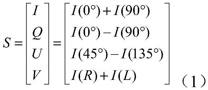
The polarization state of light is expressed by a Stokes vector, as shown in formula (1), where S represents the Stokes vector, which is a 4 × 1 vector, and I, Q, U, V are four polarization components, respectively. I denotes the sum of the light intensity at 0 ° linear polarization component (I (0 °)) and 90 ° linear polarization component (I (90 °)), Q denotes the difference between the light intensity at 0 ° linear polarization component and 90 ° linear polarization component, U is the difference between the light intensity at 45 ° linear polarization component (I (45 °)) and 135 ° linear polarization component (I (135 °)), and V is the difference between the light intensity at right-hand circular polarization component (I (r)) and left-hand circular polarization component (I (l)).
Certain combinations of the outgoing Stokes vectors in a certain incident polarization state can well characterize the particles, and the specific polarization property is a specific parameter. The polarization parameters of the particles can be extracted through the type of incident light, the selection of the polarization components, the operation and combination among the polarization components, and the like, so that the identification of the particles is realized. Meanwhile, due to the difference of the pigment composition in the particles, the wavelength and the intensity of the excited fluorescence have specific expression due to the difference of the particles.
In the embodiment of the invention, single measurement of the particulate matter can be realized through the limitation of the detection volume, so that a pulse signal is received through a photoelectric converter (such as a photomultiplier tube PMT), and then the Stokes vector of the emergent light is calculated and the excitation fluorescence intensity is obtained. If the excitation fluorescence intensity is close to or approaches 0, the particles can be identified as non-biological particles or particles without pigment; when the excitation fluorescence intensity is strong, the particles can be identified as biological microparticles containing a pigment, and the microparticles can be distinguished according to the intensity. The accuracy of particle identification is greatly improved by using the data of Stokes vectors and the excitation fluorescence intensity, namely combining the factors such as the structure, the pigment and the like of the particles.
The background of the present invention may contain background information related to the problem or environment of the present invention and does not necessarily describe the prior art. Accordingly, the inclusion in the background section is not an admission of prior art by the applicant.
The foregoing is a more detailed description of the invention in connection with specific/preferred embodiments and is not intended to limit the practice of the invention to those descriptions. It will be apparent to those skilled in the art that various substitutions and modifications can be made to the described embodiments without departing from the spirit of the invention, and these substitutions and modifications should be considered to fall within the scope of the invention. In the description herein, references to the description of the term "one embodiment," "some embodiments," "preferred embodiments," "an example," "a specific example," or "some examples" or the like are intended to mean that a particular feature, structure, material, or characteristic described in connection with the embodiment or example is included in at least one embodiment or example of the invention. In this specification, the schematic representations of the terms used above are not necessarily intended to refer to the same embodiment or example. Furthermore, the particular features, structures, materials, or characteristics described may be combined in any suitable manner in any one or more embodiments or examples. Various embodiments or examples and features of various embodiments or examples described in this specification can be combined and combined by one skilled in the art without contradiction. Although embodiments of the present invention and their advantages have been described in detail, it should be understood that various changes, substitutions and alterations can be made herein without departing from the scope of the claims.
Claims (10)
1. A synchronous measurement device for suspended particle polarized fluorescence is characterized by comprising a light source, a polarizing device, an incident polarized light path, a scattered light receiving light path, a light splitter, a signal receiving device and a data processing end, wherein incident polarized light is generated after light emitted by the light source passes through the polarizing device, suspended particles in liquid are irradiated through the incident polarized light path, the scattered light receiving light path receives scattered light signals from the irradiated suspended particles and transmits the scattered light signals to the light splitter, the scattered light signals are split by the light splitter, then excitation fluorescent signals and polarization scattered signals are output by a fluorescence detection light splitting channel and a polarization detection light splitting channel of the light splitter respectively, and then the signals are received by the signal receiving device and transmitted to the data processing end, so that the polarization scattered signals and the excitation fluorescent signals of the suspended particles are obtained simultaneously, and combining the polarization scattering characteristic and the excited fluorescence characteristic to distinguish and identify the suspended particles.
2. The device for the simultaneous polarized fluorescence measurement of suspended particles according to claim 1, wherein the incident polarized light path comprises an aperture and a first lens, the aperture attenuates the incident polarized light, and the first lens focuses the attenuated polarized light to irradiate the suspended particles.
3. The suspended particle polarized fluorescence synchronous measurement device of claim 1 or 2, wherein the scattered light receiving optical path is disposed at a backscattering angle of the suspended particulate matter relative to the incident polarized light optical path.
4. The device for synchronously measuring the polarized fluorescence of the suspended particles as claimed in any one of claims 1 to 3, wherein the scattered light receiving optical path comprises a second lens, a pinhole and a third lens, the scattered light is converged at the pinhole through the second lens, forms divergent light after being spatially filtered by the pinhole, and is modulated into a single beam of parallel light through the third lens, and the single beam of parallel light is split into a plurality of beams of light after entering the beam splitter and enters the fluorescence detection splitting channel and the plurality of sub-channels of the polarization detection splitting channel.
5. The apparatus for simultaneous polarized fluorescence measurement of suspended particles according to any of claims 1 to 4, wherein the path of the incident polarized light and the path of the scattered light intersect in a small region such that only the suspended particles in the region can be detected as their scattered signal.
6. The synchronous measurement device for polarized fluorescence of suspended particles according to any one of claims 1 to 5, wherein a filter for incident light wavelength is disposed at the fluorescence detection light splitting channel, so as to filter out scattered light of the incident light, so that excited fluorescence generated by the suspended particles passes through, and after being converted by the photoelectric converter, the signal is transmitted to the data processing end by the receiving device, and the data processing end calculates the intensity and/or wavelength of the excited fluorescence to realize interpretation of the fluorescence characteristics of the suspended particles.
7. The device for the simultaneous polarized fluorescence measurement of suspended particles according to any of claims 1 to 6, wherein the polarization state of the light is measured by means of amplitude-division, wave-division front or wavelength-division light modulation.
8. The suspended particle polarized fluorescence synchronous measurement device as claimed in any one of claims 1 to 6, wherein an amplitude-splitting measurement mode is adopted, the polarization analysis light-splitting channel comprises four sub-channels, the emergent light is divided into four parts, each sub-channel is respectively added with a horizontal polarizing plate, a 135-degree polarizing plate and a 45-degree polarizing plate, and a left-handed polarizing plate, namely a 90-degree polarizing plate and an 1/4 wave plate, so as to realize the polarization analysis of the emergent light, after the emergent light is converted by a photoelectric converter, a signal is transmitted to the data processing end by the receiving device, and the data processing end calculates a Stokes vector so as to realize the interpretation of the polarization characteristic of the suspended particles.
9. The device for simultaneous polarized fluorescence measurement of suspended particles according to claim 6 or 8, wherein the photoelectric converter is a photomultiplier tube.
10. The suspended particle polarized fluorescence synchronous measurement device of any one of claims 1 to 9, wherein the signal-to-noise ratio of the polarized scattered signal and the excited fluorescence signal is adjusted by controlling the optical power, wavelength, pulse or continuous illumination of the light source.
Priority Applications (1)
| Application Number | Priority Date | Filing Date | Title |
|---|---|---|---|
| CN202010126352.7A CN111337392A (en) | 2020-02-28 | 2020-02-28 | Suspended particle polarized fluorescence synchronous measurement device |
Applications Claiming Priority (1)
| Application Number | Priority Date | Filing Date | Title |
|---|---|---|---|
| CN202010126352.7A CN111337392A (en) | 2020-02-28 | 2020-02-28 | Suspended particle polarized fluorescence synchronous measurement device |
Publications (1)
| Publication Number | Publication Date |
|---|---|
| CN111337392A true CN111337392A (en) | 2020-06-26 |
Family
ID=71185671
Family Applications (1)
| Application Number | Title | Priority Date | Filing Date |
|---|---|---|---|
| CN202010126352.7A Pending CN111337392A (en) | 2020-02-28 | 2020-02-28 | Suspended particle polarized fluorescence synchronous measurement device |
Country Status (1)
| Country | Link |
|---|---|
| CN (1) | CN111337392A (en) |
Cited By (8)
| Publication number | Priority date | Publication date | Assignee | Title |
|---|---|---|---|---|
| CN111812000A (en) * | 2020-07-02 | 2020-10-23 | 清华大学深圳国际研究生院 | Detection device and method for suspended single particles |
| CN112557362A (en) * | 2020-12-04 | 2021-03-26 | 厦门大学 | Synchronous fluorescence spectrum detection method using LED light source as continuous wave excitation light source |
| CN113218876A (en) * | 2021-04-30 | 2021-08-06 | 清华大学深圳国际研究生院 | Method and device for quickly measuring Mueller matrix of suspended particulate matters |
| CN113456069A (en) * | 2021-07-28 | 2021-10-01 | 清华大学深圳国际研究生院 | Device and equipment for near-infrared detection of blood sugar based on polarized light imaging |
| CN113588502A (en) * | 2021-07-07 | 2021-11-02 | 清华大学深圳国际研究生院 | Device and method for synchronously measuring polarization and excitation emission spectrum of suspended particulate matters in water body |
| CN114018790A (en) * | 2021-10-25 | 2022-02-08 | 佛山科学技术学院 | Flow type particle detection device |
| CN114018766A (en) * | 2021-10-22 | 2022-02-08 | 佛山科学技术学院 | A Multiwavelength Scattering Polarized Fluorescence Measurement Device |
| CN117783025A (en) * | 2023-12-26 | 2024-03-29 | 安徽建筑大学 | Multi-wavelength and multi-angle three-dimensional spectral detection method and device for bacterial microorganisms |
Citations (6)
| Publication number | Priority date | Publication date | Assignee | Title |
|---|---|---|---|---|
| US7113266B1 (en) * | 2005-03-30 | 2006-09-26 | Beckman Coulter, Inc. | Flow cytometer for differentiating small particles in suspension |
| WO2009064868A1 (en) * | 2007-11-14 | 2009-05-22 | Droplet Measurement Technololies | Bioaerosol measuremeny system |
| JP2011149822A (en) * | 2010-01-21 | 2011-08-04 | Sony Corp | Optical measuring device and optical measuring method |
| CN103940709A (en) * | 2014-05-06 | 2014-07-23 | 南京中科神光科技有限公司 | Real-time microbial particle counter |
| US20170315045A1 (en) * | 2016-05-02 | 2017-11-02 | Hamilton Associates, Inc. | Realtime optical method and system for detecting and classifying biological and non-biological particles |
| US20210033593A1 (en) * | 2018-04-28 | 2021-02-04 | Shenzhen Mindray Bio-Medical Electronics Co., Ltd. | Methods and systems for determining platelet concentration |
-
2020
- 2020-02-28 CN CN202010126352.7A patent/CN111337392A/en active Pending
Patent Citations (6)
| Publication number | Priority date | Publication date | Assignee | Title |
|---|---|---|---|---|
| US7113266B1 (en) * | 2005-03-30 | 2006-09-26 | Beckman Coulter, Inc. | Flow cytometer for differentiating small particles in suspension |
| WO2009064868A1 (en) * | 2007-11-14 | 2009-05-22 | Droplet Measurement Technololies | Bioaerosol measuremeny system |
| JP2011149822A (en) * | 2010-01-21 | 2011-08-04 | Sony Corp | Optical measuring device and optical measuring method |
| CN103940709A (en) * | 2014-05-06 | 2014-07-23 | 南京中科神光科技有限公司 | Real-time microbial particle counter |
| US20170315045A1 (en) * | 2016-05-02 | 2017-11-02 | Hamilton Associates, Inc. | Realtime optical method and system for detecting and classifying biological and non-biological particles |
| US20210033593A1 (en) * | 2018-04-28 | 2021-02-04 | Shenzhen Mindray Bio-Medical Electronics Co., Ltd. | Methods and systems for determining platelet concentration |
Non-Patent Citations (1)
| Title |
|---|
| 李嘉晋 等: "利用偏振光散射技术的藻类絮凝过程监测", 《大气与环境光学学报》 * |
Cited By (11)
| Publication number | Priority date | Publication date | Assignee | Title |
|---|---|---|---|---|
| CN111812000A (en) * | 2020-07-02 | 2020-10-23 | 清华大学深圳国际研究生院 | Detection device and method for suspended single particles |
| CN111812000B (en) * | 2020-07-02 | 2024-03-22 | 清华大学深圳国际研究生院 | Detection device and method for suspended single particles |
| CN112557362A (en) * | 2020-12-04 | 2021-03-26 | 厦门大学 | Synchronous fluorescence spectrum detection method using LED light source as continuous wave excitation light source |
| CN112557362B (en) * | 2020-12-04 | 2022-08-23 | 厦门大学 | Synchronous fluorescence spectrum detection method using LED light source as continuous wave excitation light source |
| CN113218876A (en) * | 2021-04-30 | 2021-08-06 | 清华大学深圳国际研究生院 | Method and device for quickly measuring Mueller matrix of suspended particulate matters |
| CN113588502A (en) * | 2021-07-07 | 2021-11-02 | 清华大学深圳国际研究生院 | Device and method for synchronously measuring polarization and excitation emission spectrum of suspended particulate matters in water body |
| CN113456069A (en) * | 2021-07-28 | 2021-10-01 | 清华大学深圳国际研究生院 | Device and equipment for near-infrared detection of blood sugar based on polarized light imaging |
| CN113456069B (en) * | 2021-07-28 | 2023-07-04 | 清华大学深圳国际研究生院 | Device and equipment for near infrared blood sugar detection based on polarized light imaging |
| CN114018766A (en) * | 2021-10-22 | 2022-02-08 | 佛山科学技术学院 | A Multiwavelength Scattering Polarized Fluorescence Measurement Device |
| CN114018790A (en) * | 2021-10-25 | 2022-02-08 | 佛山科学技术学院 | Flow type particle detection device |
| CN117783025A (en) * | 2023-12-26 | 2024-03-29 | 安徽建筑大学 | Multi-wavelength and multi-angle three-dimensional spectral detection method and device for bacterial microorganisms |
Similar Documents
| Publication | Publication Date | Title |
|---|---|---|
| CN111337392A (en) | Suspended particle polarized fluorescence synchronous measurement device | |
| US12078587B2 (en) | Cell sorting using a high throughput fluorescence flow cytometer | |
| CN111366558A (en) | Multi-wavelength polarization scattering measuring device | |
| CN111366510B (en) | Suspended particulate matter flux measuring device utilizing synchronous polarization and fluorescence | |
| US12436087B2 (en) | Spectral unmixing of fluorescence imaging using radiofrequency-multiplexed excitation data | |
| EP2843410B1 (en) | Sample analyzing method and sample analyzer | |
| CN110530783B (en) | Lateral beam collection method and device for flow cytometer and flow cytometer | |
| JPH0792076A (en) | Particle analyzer | |
| JPH04188043A (en) | Specimen measuring apparatus | |
| JPH04188045A (en) | Sample measuring device | |
| JPH04188041A (en) | Sample measuring device | |
| CN113588502A (en) | Device and method for synchronously measuring polarization and excitation emission spectrum of suspended particulate matters in water body | |
| CN114813706B (en) | Blood cell hyperspectral optical tweezers capture energy resonance transfer analyzer | |
| CN111812000A (en) | Detection device and method for suspended single particles | |
| JPH04188044A (en) | Specimen measuring apparatus | |
| JPH03197840A (en) | Particle analyzing device |
Legal Events
| Date | Code | Title | Description |
|---|---|---|---|
| PB01 | Publication | ||
| PB01 | Publication | ||
| SE01 | Entry into force of request for substantive examination | ||
| SE01 | Entry into force of request for substantive examination | ||
| RJ01 | Rejection of invention patent application after publication |
Application publication date: 20200626 |
|
| RJ01 | Rejection of invention patent application after publication |