CN111298285A - Polymer formulations for nasolacrimal stimulation - Google Patents
Polymer formulations for nasolacrimal stimulation Download PDFInfo
- Publication number
- CN111298285A CN111298285A CN202010020774.6A CN202010020774A CN111298285A CN 111298285 A CN111298285 A CN 111298285A CN 202010020774 A CN202010020774 A CN 202010020774A CN 111298285 A CN111298285 A CN 111298285A
- Authority
- CN
- China
- Prior art keywords
- hydrogel
- nasal
- tip
- hydration
- formulation
- Prior art date
- Legal status (The legal status is an assumption and is not a legal conclusion. Google has not performed a legal analysis and makes no representation as to the accuracy of the status listed.)
- Pending
Links
- 239000000203 mixture Substances 0.000 title claims abstract description 147
- 230000000638 stimulation Effects 0.000 title claims abstract description 18
- 238000009472 formulation Methods 0.000 title abstract description 124
- 229920000642 polymer Polymers 0.000 title abstract description 24
- 239000000017 hydrogel Substances 0.000 claims abstract description 373
- 238000000034 method Methods 0.000 claims abstract description 73
- 210000001519 tissue Anatomy 0.000 claims abstract description 30
- 210000004561 lacrimal apparatus Anatomy 0.000 claims abstract description 6
- 230000004936 stimulating effect Effects 0.000 claims abstract description 5
- DNIAPMSPPWPWGF-UHFFFAOYSA-N Propylene glycol Chemical compound CC(O)CO DNIAPMSPPWPWGF-UHFFFAOYSA-N 0.000 claims description 108
- 230000036571 hydration Effects 0.000 claims description 103
- 238000006703 hydration reaction Methods 0.000 claims description 103
- OKKJLVBELUTLKV-UHFFFAOYSA-N Methanol Chemical compound OC OKKJLVBELUTLKV-UHFFFAOYSA-N 0.000 claims description 57
- WHNWPMSKXPGLAX-UHFFFAOYSA-N N-Vinyl-2-pyrrolidone Chemical compound C=CN1CCCC1=O WHNWPMSKXPGLAX-UHFFFAOYSA-N 0.000 claims description 22
- WHNPOQXWAMXPTA-UHFFFAOYSA-N 3-methylbut-2-enamide Chemical compound CC(C)=CC(N)=O WHNPOQXWAMXPTA-UHFFFAOYSA-N 0.000 claims description 19
- -1 3- (trimethyloxysilyl) propyl Chemical group 0.000 claims description 11
- QRIMLDXJAPZHJE-UHFFFAOYSA-N 2,3-dihydroxypropyl 2-methylprop-2-enoate Chemical compound CC(=C)C(=O)OCC(O)CO QRIMLDXJAPZHJE-UHFFFAOYSA-N 0.000 claims description 7
- VFHVQBAGLAREND-UHFFFAOYSA-N diphenylphosphoryl-(2,4,6-trimethylphenyl)methanone Chemical compound CC1=CC(C)=CC(C)=C1C(=O)P(=O)(C=1C=CC=CC=1)C1=CC=CC=C1 VFHVQBAGLAREND-UHFFFAOYSA-N 0.000 claims description 6
- OKKRPWIIYQTPQF-UHFFFAOYSA-N Trimethylolpropane trimethacrylate Chemical compound CC(=C)C(=O)OCC(CC)(COC(=O)C(C)=C)COC(=O)C(C)=C OKKRPWIIYQTPQF-UHFFFAOYSA-N 0.000 claims description 4
- 230000003213 activating effect Effects 0.000 claims description 3
- 230000008569 process Effects 0.000 abstract description 16
- 238000004132 cross linking Methods 0.000 abstract description 10
- 238000007493 shaping process Methods 0.000 abstract description 8
- 230000001737 promoting effect Effects 0.000 abstract description 2
- 230000004489 tear production Effects 0.000 abstract description 2
- 239000000178 monomer Substances 0.000 description 106
- XLYOFNOQVPJJNP-UHFFFAOYSA-N water Substances O XLYOFNOQVPJJNP-UHFFFAOYSA-N 0.000 description 70
- 238000000605 extraction Methods 0.000 description 34
- 239000003085 diluting agent Substances 0.000 description 30
- 230000006870 function Effects 0.000 description 27
- 230000008961 swelling Effects 0.000 description 25
- 208000003556 Dry Eye Syndromes Diseases 0.000 description 21
- 206010013774 Dry eye Diseases 0.000 description 19
- 239000004020 conductor Substances 0.000 description 19
- 229920001296 polysiloxane Polymers 0.000 description 18
- 238000004519 manufacturing process Methods 0.000 description 17
- 238000001035 drying Methods 0.000 description 15
- 239000000499 gel Substances 0.000 description 15
- 238000005266 casting Methods 0.000 description 14
- 230000002209 hydrophobic effect Effects 0.000 description 13
- FAPWRFPIFSIZLT-UHFFFAOYSA-M Sodium chloride Chemical compound [Na+].[Cl-] FAPWRFPIFSIZLT-UHFFFAOYSA-M 0.000 description 12
- 239000000463 material Substances 0.000 description 12
- BLRPTPMANUNPDV-UHFFFAOYSA-N Silane Chemical compound [SiH4] BLRPTPMANUNPDV-UHFFFAOYSA-N 0.000 description 10
- 229910052757 nitrogen Inorganic materials 0.000 description 10
- 230000009286 beneficial effect Effects 0.000 description 9
- 210000001331 nose Anatomy 0.000 description 9
- 239000011780 sodium chloride Substances 0.000 description 9
- IJGRMHOSHXDMSA-UHFFFAOYSA-N Atomic nitrogen Chemical compound N#N IJGRMHOSHXDMSA-UHFFFAOYSA-N 0.000 description 8
- 229940048053 acrylate Drugs 0.000 description 8
- 229920001940 conductive polymer Polymers 0.000 description 8
- KPUWHANPEXNPJT-UHFFFAOYSA-N disiloxane Chemical class [SiH3]O[SiH3] KPUWHANPEXNPJT-UHFFFAOYSA-N 0.000 description 8
- 229910000077 silane Inorganic materials 0.000 description 8
- 229920002818 (Hydroxyethyl)methacrylate Polymers 0.000 description 7
- NIXOWILDQLNWCW-UHFFFAOYSA-M Acrylate Chemical compound [O-]C(=O)C=C NIXOWILDQLNWCW-UHFFFAOYSA-M 0.000 description 7
- WOBHKFSMXKNTIM-UHFFFAOYSA-N Hydroxyethyl methacrylate Chemical compound CC(=C)C(=O)OCCO WOBHKFSMXKNTIM-UHFFFAOYSA-N 0.000 description 7
- 238000001514 detection method Methods 0.000 description 7
- 238000007598 dipping method Methods 0.000 description 7
- STVZJERGLQHEKB-UHFFFAOYSA-N ethylene glycol dimethacrylate Chemical compound CC(=C)C(=O)OCCOC(=O)C(C)=C STVZJERGLQHEKB-UHFFFAOYSA-N 0.000 description 7
- 230000005855 radiation Effects 0.000 description 7
- 238000011282 treatment Methods 0.000 description 7
- 239000000654 additive Substances 0.000 description 5
- 239000008367 deionised water Substances 0.000 description 5
- 229910021641 deionized water Inorganic materials 0.000 description 5
- 230000009477 glass transition Effects 0.000 description 5
- 239000003999 initiator Substances 0.000 description 5
- 230000004048 modification Effects 0.000 description 5
- 238000012986 modification Methods 0.000 description 5
- 238000000465 moulding Methods 0.000 description 5
- 239000000126 substance Substances 0.000 description 5
- 239000000758 substrate Substances 0.000 description 5
- 238000012360 testing method Methods 0.000 description 5
- 229920002153 Hydroxypropyl cellulose Polymers 0.000 description 4
- 239000002202 Polyethylene glycol Substances 0.000 description 4
- 239000011888 foil Substances 0.000 description 4
- 150000004676 glycans Chemical class 0.000 description 4
- 230000000887 hydrating effect Effects 0.000 description 4
- 239000001863 hydroxypropyl cellulose Substances 0.000 description 4
- 235000010977 hydroxypropyl cellulose Nutrition 0.000 description 4
- 230000007774 longterm Effects 0.000 description 4
- 238000005259 measurement Methods 0.000 description 4
- 230000007246 mechanism Effects 0.000 description 4
- 238000002156 mixing Methods 0.000 description 4
- 229920001223 polyethylene glycol Polymers 0.000 description 4
- 238000006116 polymerization reaction Methods 0.000 description 4
- 229920001282 polysaccharide Polymers 0.000 description 4
- 239000005017 polysaccharide Substances 0.000 description 4
- 238000005507 spraying Methods 0.000 description 4
- NIXOWILDQLNWCW-UHFFFAOYSA-N 2-Propenoic acid Natural products OC(=O)C=C NIXOWILDQLNWCW-UHFFFAOYSA-N 0.000 description 3
- BESKSSIEODQWBP-UHFFFAOYSA-N 3-tris(trimethylsilyloxy)silylpropyl 2-methylprop-2-enoate Chemical compound CC(=C)C(=O)OCCC[Si](O[Si](C)(C)C)(O[Si](C)(C)C)O[Si](C)(C)C BESKSSIEODQWBP-UHFFFAOYSA-N 0.000 description 3
- DBCAQXHNJOFNGC-UHFFFAOYSA-N 4-bromo-1,1,1-trifluorobutane Chemical compound FC(F)(F)CCCBr DBCAQXHNJOFNGC-UHFFFAOYSA-N 0.000 description 3
- JHWGFJBTMHEZME-UHFFFAOYSA-N 4-prop-2-enoyloxybutyl prop-2-enoate Chemical compound C=CC(=O)OCCCCOC(=O)C=C JHWGFJBTMHEZME-UHFFFAOYSA-N 0.000 description 3
- PEDCQBHIVMGVHV-UHFFFAOYSA-N Glycerine Chemical compound OCC(O)CO PEDCQBHIVMGVHV-UHFFFAOYSA-N 0.000 description 3
- CERQOIWHTDAKMF-UHFFFAOYSA-N Methacrylic acid Chemical compound CC(=C)C(O)=O CERQOIWHTDAKMF-UHFFFAOYSA-N 0.000 description 3
- 239000004698 Polyethylene Substances 0.000 description 3
- HEMHJVSKTPXQMS-UHFFFAOYSA-M Sodium hydroxide Chemical compound [OH-].[Na+] HEMHJVSKTPXQMS-UHFFFAOYSA-M 0.000 description 3
- 238000000429 assembly Methods 0.000 description 3
- 230000000712 assembly Effects 0.000 description 3
- 230000015572 biosynthetic process Effects 0.000 description 3
- 239000012267 brine Substances 0.000 description 3
- 230000008859 change Effects 0.000 description 3
- 239000003795 chemical substances by application Substances 0.000 description 3
- 230000000295 complement effect Effects 0.000 description 3
- 238000007906 compression Methods 0.000 description 3
- 230000006835 compression Effects 0.000 description 3
- 239000003431 cross linking reagent Substances 0.000 description 3
- 238000005520 cutting process Methods 0.000 description 3
- 230000000694 effects Effects 0.000 description 3
- 238000010828 elution Methods 0.000 description 3
- 239000000284 extract Substances 0.000 description 3
- 238000011049 filling Methods 0.000 description 3
- 229920003063 hydroxymethyl cellulose Polymers 0.000 description 3
- 239000012212 insulator Substances 0.000 description 3
- 150000002500 ions Chemical class 0.000 description 3
- 229910052751 metal Inorganic materials 0.000 description 3
- 239000002184 metal Substances 0.000 description 3
- 229920000573 polyethylene Polymers 0.000 description 3
- 238000010926 purge Methods 0.000 description 3
- HPALAKNZSZLMCH-UHFFFAOYSA-M sodium;chloride;hydrate Chemical compound O.[Na+].[Cl-] HPALAKNZSZLMCH-UHFFFAOYSA-M 0.000 description 3
- 238000003860 storage Methods 0.000 description 3
- 239000004094 surface-active agent Substances 0.000 description 3
- 208000024891 symptom Diseases 0.000 description 3
- KIUKXJAPPMFGSW-DNGZLQJQSA-N (2S,3S,4S,5R,6R)-6-[(2S,3R,4R,5S,6R)-3-Acetamido-2-[(2S,3S,4R,5R,6R)-6-[(2R,3R,4R,5S,6R)-3-acetamido-2,5-dihydroxy-6-(hydroxymethyl)oxan-4-yl]oxy-2-carboxy-4,5-dihydroxyoxan-3-yl]oxy-5-hydroxy-6-(hydroxymethyl)oxan-4-yl]oxy-3,4,5-trihydroxyoxane-2-carboxylic acid Chemical compound CC(=O)N[C@H]1[C@H](O)O[C@H](CO)[C@@H](O)[C@@H]1O[C@H]1[C@H](O)[C@@H](O)[C@H](O[C@H]2[C@@H]([C@@H](O[C@H]3[C@@H]([C@@H](O)[C@H](O)[C@H](O3)C(O)=O)O)[C@H](O)[C@@H](CO)O2)NC(C)=O)[C@@H](C(O)=O)O1 KIUKXJAPPMFGSW-DNGZLQJQSA-N 0.000 description 2
- SMZOUWXMTYCWNB-UHFFFAOYSA-N 2-(2-methoxy-5-methylphenyl)ethanamine Chemical compound COC1=CC=C(C)C=C1CCN SMZOUWXMTYCWNB-UHFFFAOYSA-N 0.000 description 2
- LEJBBGNFPAFPKQ-UHFFFAOYSA-N 2-(2-prop-2-enoyloxyethoxy)ethyl prop-2-enoate Chemical compound C=CC(=O)OCCOCCOC(=O)C=C LEJBBGNFPAFPKQ-UHFFFAOYSA-N 0.000 description 2
- INQDDHNZXOAFFD-UHFFFAOYSA-N 2-[2-(2-prop-2-enoyloxyethoxy)ethoxy]ethyl prop-2-enoate Chemical compound C=CC(=O)OCCOCCOCCOC(=O)C=C INQDDHNZXOAFFD-UHFFFAOYSA-N 0.000 description 2
- YXYJVFYWCLAXHO-UHFFFAOYSA-N 2-methoxyethyl 2-methylprop-2-enoate Chemical compound COCCOC(=O)C(C)=C YXYJVFYWCLAXHO-UHFFFAOYSA-N 0.000 description 2
- JEALRYGRTHFMOF-UHFFFAOYSA-N 3-tris(trimethoxysilyloxy)silylpropyl 2-methylprop-2-enoate Chemical compound CO[Si](OC)(OC)O[Si](O[Si](OC)(OC)OC)(O[Si](OC)(OC)OC)CCCOC(=O)C(C)=C JEALRYGRTHFMOF-UHFFFAOYSA-N 0.000 description 2
- SOGAXMICEFXMKE-UHFFFAOYSA-N Butylmethacrylate Chemical compound CCCCOC(=O)C(C)=C SOGAXMICEFXMKE-UHFFFAOYSA-N 0.000 description 2
- 229920001661 Chitosan Polymers 0.000 description 2
- YFPJFKYCVYXDJK-UHFFFAOYSA-N Diphenylphosphine oxide Chemical compound C=1C=CC=CC=1[P+](=O)C1=CC=CC=C1 YFPJFKYCVYXDJK-UHFFFAOYSA-N 0.000 description 2
- 206010052804 Drug tolerance Diseases 0.000 description 2
- LYCAIKOWRPUZTN-UHFFFAOYSA-N Ethylene glycol Chemical compound OCCO LYCAIKOWRPUZTN-UHFFFAOYSA-N 0.000 description 2
- 206010020751 Hypersensitivity Diseases 0.000 description 2
- KFZMGEQAYNKOFK-UHFFFAOYSA-N Isopropanol Chemical compound CC(C)O KFZMGEQAYNKOFK-UHFFFAOYSA-N 0.000 description 2
- CERQOIWHTDAKMF-UHFFFAOYSA-M Methacrylate Chemical compound CC(=C)C([O-])=O CERQOIWHTDAKMF-UHFFFAOYSA-M 0.000 description 2
- FXHOOIRPVKKKFG-UHFFFAOYSA-N N,N-Dimethylacetamide Chemical compound CN(C)C(C)=O FXHOOIRPVKKKFG-UHFFFAOYSA-N 0.000 description 2
- 239000002033 PVDF binder Substances 0.000 description 2
- 239000004743 Polypropylene Substances 0.000 description 2
- VYPSYNLAJGMNEJ-UHFFFAOYSA-N Silicium dioxide Chemical compound O=[Si]=O VYPSYNLAJGMNEJ-UHFFFAOYSA-N 0.000 description 2
- 229920002385 Sodium hyaluronate Polymers 0.000 description 2
- GWEVSGVZZGPLCZ-UHFFFAOYSA-N Titan oxide Chemical compound O=[Ti]=O GWEVSGVZZGPLCZ-UHFFFAOYSA-N 0.000 description 2
- GUCYFKSBFREPBC-UHFFFAOYSA-N [phenyl-(2,4,6-trimethylbenzoyl)phosphoryl]-(2,4,6-trimethylphenyl)methanone Chemical compound CC1=CC(C)=CC(C)=C1C(=O)P(=O)(C=1C=CC=CC=1)C(=O)C1=C(C)C=C(C)C=C1C GUCYFKSBFREPBC-UHFFFAOYSA-N 0.000 description 2
- 230000004913 activation Effects 0.000 description 2
- 230000000996 additive effect Effects 0.000 description 2
- 239000013566 allergen Substances 0.000 description 2
- 229910052782 aluminium Inorganic materials 0.000 description 2
- XAGFODPZIPBFFR-UHFFFAOYSA-N aluminium Chemical compound [Al] XAGFODPZIPBFFR-UHFFFAOYSA-N 0.000 description 2
- 238000004458 analytical method Methods 0.000 description 2
- 230000004071 biological effect Effects 0.000 description 2
- 239000006229 carbon black Substances 0.000 description 2
- 238000004587 chromatography analysis Methods 0.000 description 2
- 230000006378 damage Effects 0.000 description 2
- 238000003066 decision tree Methods 0.000 description 2
- 230000000994 depressogenic effect Effects 0.000 description 2
- 238000003618 dip coating Methods 0.000 description 2
- XVKKIGYVKWTOKG-UHFFFAOYSA-N diphenylphosphoryl(phenyl)methanone Chemical compound C=1C=CC=CC=1P(=O)(C=1C=CC=CC=1)C(=O)C1=CC=CC=C1 XVKKIGYVKWTOKG-UHFFFAOYSA-N 0.000 description 2
- 238000006073 displacement reaction Methods 0.000 description 2
- 230000001747 exhibiting effect Effects 0.000 description 2
- 210000000744 eyelid Anatomy 0.000 description 2
- 239000000945 filler Substances 0.000 description 2
- 238000002290 gas chromatography-mass spectrometry Methods 0.000 description 2
- 230000026781 habituation Effects 0.000 description 2
- 229920002674 hyaluronan Polymers 0.000 description 2
- 229960003160 hyaluronic acid Drugs 0.000 description 2
- 230000005660 hydrophilic surface Effects 0.000 description 2
- 125000002887 hydroxy group Chemical group [H]O* 0.000 description 2
- 229940031574 hydroxymethyl cellulose Drugs 0.000 description 2
- 238000007654 immersion Methods 0.000 description 2
- 230000006872 improvement Effects 0.000 description 2
- 238000002347 injection Methods 0.000 description 2
- 239000007924 injection Substances 0.000 description 2
- 238000003780 insertion Methods 0.000 description 2
- 230000037431 insertion Effects 0.000 description 2
- 230000010354 integration Effects 0.000 description 2
- 230000001678 irradiating effect Effects 0.000 description 2
- 238000003808 methanol extraction Methods 0.000 description 2
- 238000012544 monitoring process Methods 0.000 description 2
- 210000003928 nasal cavity Anatomy 0.000 description 2
- 230000003287 optical effect Effects 0.000 description 2
- 238000000623 plasma-assisted chemical vapour deposition Methods 0.000 description 2
- 229920001155 polypropylene Polymers 0.000 description 2
- 229920002981 polyvinylidene fluoride Polymers 0.000 description 2
- USHAGKDGDHPEEY-UHFFFAOYSA-L potassium persulfate Chemical compound [K+].[K+].[O-]S(=O)(=O)OOS([O-])(=O)=O USHAGKDGDHPEEY-UHFFFAOYSA-L 0.000 description 2
- 238000012545 processing Methods 0.000 description 2
- 230000011514 reflex Effects 0.000 description 2
- 125000005373 siloxane group Chemical group [SiH2](O*)* 0.000 description 2
- 229940010747 sodium hyaluronate Drugs 0.000 description 2
- YWIVKILSMZOHHF-QJZPQSOGSA-N sodium;(2s,3s,4s,5r,6r)-6-[(2s,3r,4r,5s,6r)-3-acetamido-2-[(2s,3s,4r,5r,6r)-6-[(2r,3r,4r,5s,6r)-3-acetamido-2,5-dihydroxy-6-(hydroxymethyl)oxan-4-yl]oxy-2-carboxy-4,5-dihydroxyoxan-3-yl]oxy-5-hydroxy-6-(hydroxymethyl)oxan-4-yl]oxy-3,4,5-trihydroxyoxane-2- Chemical compound [Na+].CC(=O)N[C@H]1[C@H](O)O[C@H](CO)[C@@H](O)[C@@H]1O[C@H]1[C@H](O)[C@@H](O)[C@H](O[C@H]2[C@@H]([C@@H](O[C@H]3[C@@H]([C@@H](O)[C@H](O)[C@H](O3)C(O)=O)O)[C@H](O)[C@@H](CO)O2)NC(C)=O)[C@@H](C(O)=O)O1 YWIVKILSMZOHHF-QJZPQSOGSA-N 0.000 description 2
- 238000003756 stirring Methods 0.000 description 2
- 238000001356 surgical procedure Methods 0.000 description 2
- XKMZOFXGLBYJLS-UHFFFAOYSA-L zinc;prop-2-enoate Chemical compound [Zn+2].[O-]C(=O)C=C.[O-]C(=O)C=C XKMZOFXGLBYJLS-UHFFFAOYSA-L 0.000 description 2
- VPHFVJFCFJCFQD-UHFFFAOYSA-N (2,6-difluorophenyl)-diphenylphosphorylmethanone Chemical compound FC1=C(C(=O)P(C2=CC=CC=C2)(C2=CC=CC=C2)=O)C(=CC=C1)F VPHFVJFCFJCFQD-UHFFFAOYSA-N 0.000 description 1
- PQUXFUBNSYCQAL-UHFFFAOYSA-N 1-(2,3-difluorophenyl)ethanone Chemical compound CC(=O)C1=CC=CC(F)=C1F PQUXFUBNSYCQAL-UHFFFAOYSA-N 0.000 description 1
- SUDJRWYYYIMQTR-UHFFFAOYSA-N 1-(3-prop-2-enoyl-1,3-diazetidin-1-yl)prop-2-en-1-one Chemical compound C=CC(=O)N1CN(C(=O)C=C)C1 SUDJRWYYYIMQTR-UHFFFAOYSA-N 0.000 description 1
- 239000012956 1-hydroxycyclohexylphenyl-ketone Substances 0.000 description 1
- IXPNQXFRVYWDDI-UHFFFAOYSA-N 1-methyl-2,4-dioxo-1,3-diazinane-5-carboximidamide Chemical compound CN1CC(C(N)=N)C(=O)NC1=O IXPNQXFRVYWDDI-UHFFFAOYSA-N 0.000 description 1
- OYKPJMYWPYIXGG-UHFFFAOYSA-N 2,2-dimethylbutane;prop-2-enoic acid Chemical compound OC(=O)C=C.OC(=O)C=C.OC(=O)C=C.CCC(C)(C)C OYKPJMYWPYIXGG-UHFFFAOYSA-N 0.000 description 1
- OXBLVCZKDOZZOJ-UHFFFAOYSA-N 2,3-Dihydrothiophene Chemical compound C1CC=CS1 OXBLVCZKDOZZOJ-UHFFFAOYSA-N 0.000 description 1
- GOXQRTZXKQZDDN-UHFFFAOYSA-N 2-Ethylhexyl acrylate Chemical compound CCCCC(CC)COC(=O)C=C GOXQRTZXKQZDDN-UHFFFAOYSA-N 0.000 description 1
- QLIBJPGWWSHWBF-UHFFFAOYSA-N 2-aminoethyl methacrylate Chemical compound CC(=C)C(=O)OCCN QLIBJPGWWSHWBF-UHFFFAOYSA-N 0.000 description 1
- WUGOQZFPNUYUOO-UHFFFAOYSA-N 2-trimethylsilyloxyethyl 2-methylprop-2-enoate Chemical compound CC(=C)C(=O)OCCO[Si](C)(C)C WUGOQZFPNUYUOO-UHFFFAOYSA-N 0.000 description 1
- REEBWSYYNPPSKV-UHFFFAOYSA-N 3-[(4-formylphenoxy)methyl]thiophene-2-carbonitrile Chemical compound C1=CC(C=O)=CC=C1OCC1=C(C#N)SC=C1 REEBWSYYNPPSKV-UHFFFAOYSA-N 0.000 description 1
- ZBSZHOGQQIFYIK-UHFFFAOYSA-N 3-[hydroxy-bis(trimethylsilyloxy)silyl]propyl 2-methylprop-2-enoate Chemical compound CC(=C)C(=O)OCCC[Si](O)(O[Si](C)(C)C)O[Si](C)(C)C ZBSZHOGQQIFYIK-UHFFFAOYSA-N 0.000 description 1
- DMZPTAFGSRVFIA-UHFFFAOYSA-N 3-[tris(2-methoxyethoxy)silyl]propyl 2-methylprop-2-enoate Chemical compound COCCO[Si](OCCOC)(OCCOC)CCCOC(=O)C(C)=C DMZPTAFGSRVFIA-UHFFFAOYSA-N 0.000 description 1
- APXPPKQXWMJUJR-UHFFFAOYSA-N 3-methoxypropyl-methyl-bis(trimethylsilyloxy)silane Chemical compound COCCC[Si](C)(O[Si](C)(C)C)O[Si](C)(C)C APXPPKQXWMJUJR-UHFFFAOYSA-N 0.000 description 1
- HRPVXLWXLXDGHG-UHFFFAOYSA-N Acrylamide Chemical compound NC(=O)C=C HRPVXLWXLXDGHG-UHFFFAOYSA-N 0.000 description 1
- 238000006596 Alder-ene reaction Methods 0.000 description 1
- 208000002177 Cataract Diseases 0.000 description 1
- 229920002101 Chitin Polymers 0.000 description 1
- PMATZTZNYRCHOR-CGLBZJNRSA-N Cyclosporin A Chemical compound CC[C@@H]1NC(=O)[C@H]([C@H](O)[C@H](C)C\C=C\C)N(C)C(=O)[C@H](C(C)C)N(C)C(=O)[C@H](CC(C)C)N(C)C(=O)[C@H](CC(C)C)N(C)C(=O)[C@@H](C)NC(=O)[C@H](C)NC(=O)[C@H](CC(C)C)N(C)C(=O)[C@H](C(C)C)NC(=O)[C@H](CC(C)C)N(C)C(=O)CN(C)C1=O PMATZTZNYRCHOR-CGLBZJNRSA-N 0.000 description 1
- 108010036949 Cyclosporine Proteins 0.000 description 1
- 229920002307 Dextran Polymers 0.000 description 1
- 208000030453 Drug-Related Side Effects and Adverse reaction Diseases 0.000 description 1
- 239000004593 Epoxy Substances 0.000 description 1
- JIGUQPWFLRLWPJ-UHFFFAOYSA-N Ethyl acrylate Chemical compound CCOC(=O)C=C JIGUQPWFLRLWPJ-UHFFFAOYSA-N 0.000 description 1
- UFHFLCQGNIYNRP-UHFFFAOYSA-N Hydrogen Chemical compound [H][H] UFHFLCQGNIYNRP-UHFFFAOYSA-N 0.000 description 1
- 206010061218 Inflammation Diseases 0.000 description 1
- 206010065062 Meibomian gland dysfunction Diseases 0.000 description 1
- 229910003849 O-Si Inorganic materials 0.000 description 1
- HIJJQQSZGMTXFV-UHFFFAOYSA-N OCCO.OC(=O)C=C.OC(=O)C=C.OC(=O)C=C Chemical compound OCCO.OC(=O)C=C.OC(=O)C=C.OC(=O)C=C HIJJQQSZGMTXFV-UHFFFAOYSA-N 0.000 description 1
- 208000023715 Ocular surface disease Diseases 0.000 description 1
- 229910003872 O—Si Inorganic materials 0.000 description 1
- 239000004734 Polyphenylene sulfide Substances 0.000 description 1
- 239000004793 Polystyrene Substances 0.000 description 1
- 206010039710 Scleroderma Diseases 0.000 description 1
- 208000021386 Sjogren Syndrome Diseases 0.000 description 1
- DBMJMQXJHONAFJ-UHFFFAOYSA-M Sodium laurylsulphate Chemical compound [Na+].CCCCCCCCCCCCOS([O-])(=O)=O DBMJMQXJHONAFJ-UHFFFAOYSA-M 0.000 description 1
- 244000028419 Styrax benzoin Species 0.000 description 1
- 235000000126 Styrax benzoin Nutrition 0.000 description 1
- 235000008411 Sumatra benzointree Nutrition 0.000 description 1
- LFOXEOLGJPJZAA-UHFFFAOYSA-N [(2,6-dimethoxybenzoyl)-(2,4,4-trimethylpentyl)phosphoryl]-(2,6-dimethoxyphenyl)methanone Chemical compound COC1=CC=CC(OC)=C1C(=O)P(=O)(CC(C)CC(C)(C)C)C(=O)C1=C(OC)C=CC=C1OC LFOXEOLGJPJZAA-UHFFFAOYSA-N 0.000 description 1
- HVVWZTWDBSEWIH-UHFFFAOYSA-N [2-(hydroxymethyl)-3-prop-2-enoyloxy-2-(prop-2-enoyloxymethyl)propyl] prop-2-enoate Chemical compound C=CC(=O)OCC(CO)(COC(=O)C=C)COC(=O)C=C HVVWZTWDBSEWIH-UHFFFAOYSA-N 0.000 description 1
- IEWRMZSVIVEQCP-UHFFFAOYSA-N [methoxy(phenyl)phosphoryl]-(2,4,6-trimethylphenyl)methanone Chemical compound C=1C=CC=CC=1P(=O)(OC)C(=O)C1=C(C)C=C(C)C=C1C IEWRMZSVIVEQCP-UHFFFAOYSA-N 0.000 description 1
- 230000005856 abnormality Effects 0.000 description 1
- 238000005299 abrasion Methods 0.000 description 1
- DPXJVFZANSGRMM-UHFFFAOYSA-N acetic acid;2,3,4,5,6-pentahydroxyhexanal;sodium Chemical compound [Na].CC(O)=O.OCC(O)C(O)C(O)C(O)C=O DPXJVFZANSGRMM-UHFFFAOYSA-N 0.000 description 1
- 239000002253 acid Substances 0.000 description 1
- 239000003570 air Substances 0.000 description 1
- 125000000217 alkyl group Chemical group 0.000 description 1
- 208000030961 allergic reaction Diseases 0.000 description 1
- 230000007815 allergy Effects 0.000 description 1
- PNEYBMLMFCGWSK-UHFFFAOYSA-N aluminium oxide Inorganic materials [O-2].[O-2].[O-2].[Al+3].[Al+3] PNEYBMLMFCGWSK-UHFFFAOYSA-N 0.000 description 1
- 125000003277 amino group Chemical group 0.000 description 1
- 210000003484 anatomy Anatomy 0.000 description 1
- 238000011861 anti-inflammatory therapy Methods 0.000 description 1
- 238000013459 approach Methods 0.000 description 1
- 238000003491 array Methods 0.000 description 1
- 239000000607 artificial tear Substances 0.000 description 1
- QVGXLLKOCUKJST-UHFFFAOYSA-N atomic oxygen Chemical compound [O] QVGXLLKOCUKJST-UHFFFAOYSA-N 0.000 description 1
- 229960000686 benzalkonium chloride Drugs 0.000 description 1
- 229960002130 benzoin Drugs 0.000 description 1
- 239000012965 benzophenone Substances 0.000 description 1
- 150000008366 benzophenones Chemical class 0.000 description 1
- 125000001797 benzyl group Chemical group [H]C1=C([H])C([H])=C(C([H])=C1[H])C([H])([H])* 0.000 description 1
- CADWTSSKOVRVJC-UHFFFAOYSA-N benzyl(dimethyl)azanium;chloride Chemical compound [Cl-].C[NH+](C)CC1=CC=CC=C1 CADWTSSKOVRVJC-UHFFFAOYSA-N 0.000 description 1
- 230000001588 bifunctional effect Effects 0.000 description 1
- 239000000227 bioadhesive Substances 0.000 description 1
- MQDJYUACMFCOFT-UHFFFAOYSA-N bis[2-(1-hydroxycyclohexyl)phenyl]methanone Chemical compound C=1C=CC=C(C(=O)C=2C(=CC=CC=2)C2(O)CCCCC2)C=1C1(O)CCCCC1 MQDJYUACMFCOFT-UHFFFAOYSA-N 0.000 description 1
- 229920001400 block copolymer Polymers 0.000 description 1
- CQEYYJKEWSMYFG-UHFFFAOYSA-N butyl acrylate Chemical compound CCCCOC(=O)C=C CQEYYJKEWSMYFG-UHFFFAOYSA-N 0.000 description 1
- TXTCTCUXLQYGLA-UHFFFAOYSA-L calcium;prop-2-enoate Chemical compound [Ca+2].[O-]C(=O)C=C.[O-]C(=O)C=C TXTCTCUXLQYGLA-UHFFFAOYSA-L 0.000 description 1
- 239000002134 carbon nanofiber Substances 0.000 description 1
- 239000011852 carbon nanoparticle Substances 0.000 description 1
- 239000001768 carboxy methyl cellulose Substances 0.000 description 1
- 238000010538 cationic polymerization reaction Methods 0.000 description 1
- 229920002678 cellulose Polymers 0.000 description 1
- 239000001913 cellulose Substances 0.000 description 1
- 238000007385 chemical modification Methods 0.000 description 1
- 238000006243 chemical reaction Methods 0.000 description 1
- 238000005229 chemical vapour deposition Methods 0.000 description 1
- 229940045110 chitosan Drugs 0.000 description 1
- 230000001684 chronic effect Effects 0.000 description 1
- 229960001265 ciclosporin Drugs 0.000 description 1
- 238000004140 cleaning Methods 0.000 description 1
- FCSHDIVRCWTZOX-DVTGEIKXSA-N clobetasol Chemical compound C1CC2=CC(=O)C=C[C@]2(C)[C@]2(F)[C@@H]1[C@@H]1C[C@H](C)[C@@](C(=O)CCl)(O)[C@@]1(C)C[C@@H]2O FCSHDIVRCWTZOX-DVTGEIKXSA-N 0.000 description 1
- 238000004891 communication Methods 0.000 description 1
- 238000010668 complexation reaction Methods 0.000 description 1
- 150000001875 compounds Chemical class 0.000 description 1
- 238000001816 cooling Methods 0.000 description 1
- 239000011258 core-shell material Substances 0.000 description 1
- 210000004087 cornea Anatomy 0.000 description 1
- 238000012937 correction Methods 0.000 description 1
- 239000003246 corticosteroid Substances 0.000 description 1
- 229960001334 corticosteroids Drugs 0.000 description 1
- 239000002537 cosmetic Substances 0.000 description 1
- 229920006037 cross link polymer Polymers 0.000 description 1
- 150000003983 crown ethers Chemical class 0.000 description 1
- YQHLDYVWEZKEOX-UHFFFAOYSA-N cumene hydroperoxide Chemical compound OOC(C)(C)C1=CC=CC=C1 YQHLDYVWEZKEOX-UHFFFAOYSA-N 0.000 description 1
- 229930182912 cyclosporin Natural products 0.000 description 1
- 230000018044 dehydration Effects 0.000 description 1
- 238000006297 dehydration reaction Methods 0.000 description 1
- ISAOCJYIOMOJEB-UHFFFAOYSA-N desyl alcohol Natural products C=1C=CC=CC=1C(O)C(=O)C1=CC=CC=C1 ISAOCJYIOMOJEB-UHFFFAOYSA-N 0.000 description 1
- 229960002086 dextran Drugs 0.000 description 1
- 229960000633 dextran sulfate Drugs 0.000 description 1
- 125000004386 diacrylate group Chemical group 0.000 description 1
- ANUFXNUWGABVIN-UHFFFAOYSA-N diphenylphosphoryl(naphthalen-1-yl)methanone Chemical compound C=1C=CC2=CC=CC=C2C=1C(=O)P(=O)(C=1C=CC=CC=1)C1=CC=CC=C1 ANUFXNUWGABVIN-UHFFFAOYSA-N 0.000 description 1
- PODOEQVNFJSWIK-UHFFFAOYSA-N diphenylphosphoryl-(2,4,6-trimethoxyphenyl)methanone Chemical compound COC1=CC(OC)=CC(OC)=C1C(=O)P(=O)(C=1C=CC=CC=1)C1=CC=CC=C1 PODOEQVNFJSWIK-UHFFFAOYSA-N 0.000 description 1
- 210000003717 douglas' pouch Anatomy 0.000 description 1
- 238000002651 drug therapy Methods 0.000 description 1
- 239000000428 dust Substances 0.000 description 1
- 230000007613 environmental effect Effects 0.000 description 1
- 210000000981 epithelium Anatomy 0.000 description 1
- SUPCQIBBMFXVTL-UHFFFAOYSA-N ethyl 2-methylprop-2-enoate Chemical compound CCOC(=O)C(C)=C SUPCQIBBMFXVTL-UHFFFAOYSA-N 0.000 description 1
- 238000001704 evaporation Methods 0.000 description 1
- 238000002474 experimental method Methods 0.000 description 1
- 239000012530 fluid Substances 0.000 description 1
- 239000011521 glass Substances 0.000 description 1
- VOZRXNHHFUQHIL-UHFFFAOYSA-N glycidyl methacrylate Chemical compound CC(=C)C(=O)OCC1CO1 VOZRXNHHFUQHIL-UHFFFAOYSA-N 0.000 description 1
- 230000005484 gravity Effects 0.000 description 1
- 235000019382 gum benzoic Nutrition 0.000 description 1
- 238000010438 heat treatment Methods 0.000 description 1
- 230000003054 hormonal effect Effects 0.000 description 1
- 150000004677 hydrates Chemical class 0.000 description 1
- 239000001257 hydrogen Substances 0.000 description 1
- 229910052739 hydrogen Inorganic materials 0.000 description 1
- 150000002433 hydrophilic molecules Chemical class 0.000 description 1
- 229920001477 hydrophilic polymer Polymers 0.000 description 1
- 230000005661 hydrophobic surface Effects 0.000 description 1
- WGCNASOHLSPBMP-UHFFFAOYSA-N hydroxyacetaldehyde Natural products OCC=O WGCNASOHLSPBMP-UHFFFAOYSA-N 0.000 description 1
- 125000004029 hydroxymethyl group Chemical group [H]OC([H])([H])* 0.000 description 1
- 229940071676 hydroxypropylcellulose Drugs 0.000 description 1
- 239000002955 immunomodulating agent Substances 0.000 description 1
- 229940121354 immunomodulator Drugs 0.000 description 1
- 239000012535 impurity Substances 0.000 description 1
- 238000000338 in vitro Methods 0.000 description 1
- 238000011534 incubation Methods 0.000 description 1
- 239000012442 inert solvent Substances 0.000 description 1
- 230000002757 inflammatory effect Effects 0.000 description 1
- 230000004054 inflammatory process Effects 0.000 description 1
- 230000007794 irritation Effects 0.000 description 1
- 239000007788 liquid Substances 0.000 description 1
- 239000000314 lubricant Substances 0.000 description 1
- 206010025135 lupus erythematosus Diseases 0.000 description 1
- 230000014759 maintenance of location Effects 0.000 description 1
- 238000009115 maintenance therapy Methods 0.000 description 1
- 239000002609 medium Substances 0.000 description 1
- 239000002923 metal particle Substances 0.000 description 1
- FQPSGWSUVKBHSU-UHFFFAOYSA-N methacrylamide Chemical compound CC(=C)C(N)=O FQPSGWSUVKBHSU-UHFFFAOYSA-N 0.000 description 1
- YDKNBNOOCSNPNS-UHFFFAOYSA-N methyl 1,3-benzoxazole-2-carboxylate Chemical compound C1=CC=C2OC(C(=O)OC)=NC2=C1 YDKNBNOOCSNPNS-UHFFFAOYSA-N 0.000 description 1
- 125000002496 methyl group Chemical group [H]C([H])([H])* 0.000 description 1
- 238000001053 micromoulding Methods 0.000 description 1
- 239000004005 microsphere Substances 0.000 description 1
- 238000002715 modification method Methods 0.000 description 1
- 239000003607 modifier Substances 0.000 description 1
- 210000004877 mucosa Anatomy 0.000 description 1
- WFKDPJRCBCBQNT-UHFFFAOYSA-N n,2-dimethylprop-2-enamide Chemical compound CNC(=O)C(C)=C WFKDPJRCBCBQNT-UHFFFAOYSA-N 0.000 description 1
- 210000002850 nasal mucosa Anatomy 0.000 description 1
- 210000004083 nasolacrimal duct Anatomy 0.000 description 1
- 210000005036 nerve Anatomy 0.000 description 1
- 230000010004 neural pathway Effects 0.000 description 1
- 210000000118 neural pathway Anatomy 0.000 description 1
- 230000007935 neutral effect Effects 0.000 description 1
- 231100000344 non-irritating Toxicity 0.000 description 1
- 229920005787 opaque polymer Polymers 0.000 description 1
- 239000001301 oxygen Substances 0.000 description 1
- 229910052760 oxygen Inorganic materials 0.000 description 1
- 239000005022 packaging material Substances 0.000 description 1
- 238000004806 packaging method and process Methods 0.000 description 1
- 239000002245 particle Substances 0.000 description 1
- PNJWIWWMYCMZRO-UHFFFAOYSA-N pent‐4‐en‐2‐one Natural products CC(=O)CC=C PNJWIWWMYCMZRO-UHFFFAOYSA-N 0.000 description 1
- 238000009832 plasma treatment Methods 0.000 description 1
- 229920000767 polyaniline Polymers 0.000 description 1
- 229920000069 polyphenylene sulfide Polymers 0.000 description 1
- 229920000128 polypyrrole Polymers 0.000 description 1
- 229920002223 polystyrene Polymers 0.000 description 1
- 229920005996 polystyrene-poly(ethylene-butylene)-polystyrene Polymers 0.000 description 1
- 239000002243 precursor Substances 0.000 description 1
- 238000002360 preparation method Methods 0.000 description 1
- 239000003755 preservative agent Substances 0.000 description 1
- 230000000069 prophylactic effect Effects 0.000 description 1
- 230000009467 reduction Effects 0.000 description 1
- 210000001533 respiratory mucosa Anatomy 0.000 description 1
- 230000004044 response Effects 0.000 description 1
- 238000007151 ring opening polymerisation reaction Methods 0.000 description 1
- 150000003839 salts Chemical class 0.000 description 1
- 229920006395 saturated elastomer Polymers 0.000 description 1
- 230000001932 seasonal effect Effects 0.000 description 1
- 238000000926 separation method Methods 0.000 description 1
- 239000000377 silicon dioxide Substances 0.000 description 1
- 229940047670 sodium acrylate Drugs 0.000 description 1
- 239000000661 sodium alginate Substances 0.000 description 1
- 235000010413 sodium alginate Nutrition 0.000 description 1
- 229940005550 sodium alginate Drugs 0.000 description 1
- 235000019812 sodium carboxymethyl cellulose Nutrition 0.000 description 1
- 229920001027 sodium carboxymethylcellulose Polymers 0.000 description 1
- 235000019333 sodium laurylsulphate Nutrition 0.000 description 1
- NNMHYFLPFNGQFZ-UHFFFAOYSA-M sodium polyacrylate Chemical compound [Na+].[O-]C(=O)C=C NNMHYFLPFNGQFZ-UHFFFAOYSA-M 0.000 description 1
- 239000007787 solid Substances 0.000 description 1
- 239000000243 solution Substances 0.000 description 1
- 230000001954 sterilising effect Effects 0.000 description 1
- 238000004659 sterilization and disinfection Methods 0.000 description 1
- 230000003685 thermal hair damage Effects 0.000 description 1
- 230000006016 thyroid dysfunction Effects 0.000 description 1
- PGQNYIRJCLTTOJ-UHFFFAOYSA-N trimethylsilyl 2-methylprop-2-enoate Chemical compound CC(=C)C(=O)O[Si](C)(C)C PGQNYIRJCLTTOJ-UHFFFAOYSA-N 0.000 description 1
- NYHMLROEJNBVEF-UHFFFAOYSA-N tris(trimethylsilyloxy)silylmethyl 2-methylprop-2-enoate Chemical compound CC(=C)C(=O)OC[Si](O[Si](C)(C)C)(O[Si](C)(C)C)O[Si](C)(C)C NYHMLROEJNBVEF-UHFFFAOYSA-N 0.000 description 1
- GPRLSGONYQIRFK-MNYXATJNSA-N triton Chemical compound [3H+] GPRLSGONYQIRFK-MNYXATJNSA-N 0.000 description 1
- 238000002604 ultrasonography Methods 0.000 description 1
- 238000009281 ultraviolet germicidal irradiation Methods 0.000 description 1
- 125000000391 vinyl group Chemical group [H]C([*])=C([H])[H] 0.000 description 1
- 229920002554 vinyl polymer Polymers 0.000 description 1
- 238000005406 washing Methods 0.000 description 1
- 238000003466 welding Methods 0.000 description 1
Images


Classifications
-
- A—HUMAN NECESSITIES
- A61—MEDICAL OR VETERINARY SCIENCE; HYGIENE
- A61N—ELECTROTHERAPY; MAGNETOTHERAPY; RADIATION THERAPY; ULTRASOUND THERAPY
- A61N1/00—Electrotherapy; Circuits therefor
- A61N1/02—Details
- A61N1/04—Electrodes
- A61N1/05—Electrodes for implantation or insertion into the body, e.g. heart electrode
- A61N1/0526—Head electrodes
- A61N1/0546—Nasal electrodes
-
- A—HUMAN NECESSITIES
- A61—MEDICAL OR VETERINARY SCIENCE; HYGIENE
- A61N—ELECTROTHERAPY; MAGNETOTHERAPY; RADIATION THERAPY; ULTRASOUND THERAPY
- A61N1/00—Electrotherapy; Circuits therefor
- A61N1/02—Details
- A61N1/04—Electrodes
- A61N1/0404—Electrodes for external use
- A61N1/0408—Use-related aspects
- A61N1/0456—Specially adapted for transcutaneous electrical nerve stimulation [TENS]
-
- A—HUMAN NECESSITIES
- A61—MEDICAL OR VETERINARY SCIENCE; HYGIENE
- A61N—ELECTROTHERAPY; MAGNETOTHERAPY; RADIATION THERAPY; ULTRASOUND THERAPY
- A61N1/00—Electrotherapy; Circuits therefor
- A61N1/18—Applying electric currents by contact electrodes
-
- C—CHEMISTRY; METALLURGY
- C07—ORGANIC CHEMISTRY
- C07C—ACYCLIC OR CARBOCYCLIC COMPOUNDS
- C07C233/00—Carboxylic acid amides
-
- C—CHEMISTRY; METALLURGY
- C07—ORGANIC CHEMISTRY
- C07C—ACYCLIC OR CARBOCYCLIC COMPOUNDS
- C07C69/00—Esters of carboxylic acids; Esters of carbonic or haloformic acids
- C07C69/52—Esters of acyclic unsaturated carboxylic acids having the esterified carboxyl group bound to an acyclic carbon atom
-
- C—CHEMISTRY; METALLURGY
- C08—ORGANIC MACROMOLECULAR COMPOUNDS; THEIR PREPARATION OR CHEMICAL WORKING-UP; COMPOSITIONS BASED THEREON
- C08F—MACROMOLECULAR COMPOUNDS OBTAINED BY REACTIONS ONLY INVOLVING CARBON-TO-CARBON UNSATURATED BONDS
- C08F220/00—Copolymers of compounds having one or more unsaturated aliphatic radicals, each having only one carbon-to-carbon double bond, and only one being terminated by only one carboxyl radical or a salt, anhydride ester, amide, imide or nitrile thereof
- C08F220/02—Monocarboxylic acids having less than ten carbon atoms; Derivatives thereof
- C08F220/10—Esters
- C08F220/20—Esters of polyhydric alcohols or phenols, e.g. 2-hydroxyethyl (meth)acrylate or glycerol mono-(meth)acrylate
-
- C—CHEMISTRY; METALLURGY
- C08—ORGANIC MACROMOLECULAR COMPOUNDS; THEIR PREPARATION OR CHEMICAL WORKING-UP; COMPOSITIONS BASED THEREON
- C08F—MACROMOLECULAR COMPOUNDS OBTAINED BY REACTIONS ONLY INVOLVING CARBON-TO-CARBON UNSATURATED BONDS
- C08F220/00—Copolymers of compounds having one or more unsaturated aliphatic radicals, each having only one carbon-to-carbon double bond, and only one being terminated by only one carboxyl radical or a salt, anhydride ester, amide, imide or nitrile thereof
- C08F220/02—Monocarboxylic acids having less than ten carbon atoms; Derivatives thereof
- C08F220/52—Amides or imides
- C08F220/54—Amides, e.g. N,N-dimethylacrylamide or N-isopropylacrylamide
-
- H—ELECTRICITY
- H01—ELECTRIC ELEMENTS
- H01B—CABLES; CONDUCTORS; INSULATORS; SELECTION OF MATERIALS FOR THEIR CONDUCTIVE, INSULATING OR DIELECTRIC PROPERTIES
- H01B1/00—Conductors or conductive bodies characterised by the conductive materials; Selection of materials as conductors
- H01B1/06—Conductors or conductive bodies characterised by the conductive materials; Selection of materials as conductors mainly consisting of other non-metallic substances
- H01B1/12—Conductors or conductive bodies characterised by the conductive materials; Selection of materials as conductors mainly consisting of other non-metallic substances organic substances
- H01B1/124—Intrinsically conductive polymers
- H01B1/125—Intrinsically conductive polymers comprising aliphatic main chains, e.g. polyactylenes
-
- A—HUMAN NECESSITIES
- A61—MEDICAL OR VETERINARY SCIENCE; HYGIENE
- A61N—ELECTROTHERAPY; MAGNETOTHERAPY; RADIATION THERAPY; ULTRASOUND THERAPY
- A61N1/00—Electrotherapy; Circuits therefor
- A61N1/02—Details
- A61N1/04—Electrodes
- A61N1/0404—Electrodes for external use
- A61N1/0472—Structure-related aspects
- A61N1/0492—Patch electrodes
- A61N1/0496—Patch electrodes characterised by using specific chemical compositions, e.g. hydrogel compositions, adhesives
-
- A—HUMAN NECESSITIES
- A61—MEDICAL OR VETERINARY SCIENCE; HYGIENE
- A61N—ELECTROTHERAPY; MAGNETOTHERAPY; RADIATION THERAPY; ULTRASOUND THERAPY
- A61N1/00—Electrotherapy; Circuits therefor
- A61N1/18—Applying electric currents by contact electrodes
- A61N1/32—Applying electric currents by contact electrodes alternating or intermittent currents
- A61N1/36—Applying electric currents by contact electrodes alternating or intermittent currents for stimulation
- A61N1/36014—External stimulators, e.g. with patch electrodes
-
- Y—GENERAL TAGGING OF NEW TECHNOLOGICAL DEVELOPMENTS; GENERAL TAGGING OF CROSS-SECTIONAL TECHNOLOGIES SPANNING OVER SEVERAL SECTIONS OF THE IPC; TECHNICAL SUBJECTS COVERED BY FORMER USPC CROSS-REFERENCE ART COLLECTIONS [XRACs] AND DIGESTS
- Y10—TECHNICAL SUBJECTS COVERED BY FORMER USPC
- Y10T—TECHNICAL SUBJECTS COVERED BY FORMER US CLASSIFICATION
- Y10T29/00—Metal working
- Y10T29/49—Method of mechanical manufacture
- Y10T29/49826—Assembling or joining
- Y10T29/49885—Assembling or joining with coating before or during assembling
Landscapes
- Health & Medical Sciences (AREA)
- Chemical & Material Sciences (AREA)
- Organic Chemistry (AREA)
- Engineering & Computer Science (AREA)
- Radiology & Medical Imaging (AREA)
- Life Sciences & Earth Sciences (AREA)
- Animal Behavior & Ethology (AREA)
- General Health & Medical Sciences (AREA)
- Public Health (AREA)
- Veterinary Medicine (AREA)
- Nuclear Medicine, Radiotherapy & Molecular Imaging (AREA)
- Biomedical Technology (AREA)
- Chemical Kinetics & Catalysis (AREA)
- Polymers & Plastics (AREA)
- Medicinal Chemistry (AREA)
- Physics & Mathematics (AREA)
- Spectroscopy & Molecular Physics (AREA)
- Otolaryngology (AREA)
- Heart & Thoracic Surgery (AREA)
- Cardiology (AREA)
- Medicinal Preparation (AREA)
- Electrotherapy Devices (AREA)
- Pharmaceuticals Containing Other Organic And Inorganic Compounds (AREA)
- Addition Polymer Or Copolymer, Post-Treatments, Or Chemical Modifications (AREA)
- Neurology (AREA)
- Processes Of Treating Macromolecular Substances (AREA)
- Neurosurgery (AREA)
- Polymerisation Methods In General (AREA)
- Materials For Medical Uses (AREA)
- Manufacturing & Machinery (AREA)
Abstract
Described herein are methods for stimulating lacrimal glands using polymer formulations for promoting electrical stimulation of nasal or sinus tissue. The polymer formulation may be a hydrogel prepared by a UV cross-linking process. The hydrogel may include components that are nasal stimulator devices that electrically stimulate the lacrimal gland to improve tear production. Additionally, described herein are devices and methods of making the nasal stimulators that include shaping the hydrogel.
Description
This application is a divisional application of chinese patent application 201580021324.6 filed on 2015, 2-month 24-day, entitled "polymer formulation for nasolachrymal stimulation".
Technical Field
Described herein are polymer formulations that provide electrical contact between an electrode and nasal or sinus tissue. In particular, hydrogel formulations crosslinked using UV radiation are described. Methods of making the hydrogel, and methods of treating dry eye using nasal stimulation devices comprising the hydrogel, are also described.
Background
Dry eye is an important ocular condition that currently cannot be permanently cured worldwide. For example, it has been estimated that The current average annual cost of treating dry eye amounts to $ 850/person (Yu, J., Andre, C.V., and Fairchild, C.J. "economic burden of dry eye in The United States: decision Tree analysis (The environmental burden of dry eye disease in The United States: a decision tree analysis)" Cornea 304 (2011): 379-. Epidemiological estimates of the frequency of dry eye disease occurrence vary widely depending on the symptoms monitored. For example, Friedman reports that the incidence of global dry eye is in the range of 5% to 35% (Friedman, N. "Impact of dry eye and Impact on quality of life)" Current Opinion in ophthalmology 21(2010): 310-.
Current treatments include the use of lubricants (e.g., hydroxymethyl and sodium carboxymethyl cellulose, commonly referred to as artificial tears), anti-inflammatory therapies (e.g., corticosteroids and immunomodulators such as cyclosporine), tear-maintenance therapies (e.g., punctal plugs), and treatment of underlying causes such as meibomian gland dysfunction, eyelid abnormalities, and the like. These treatments have been shown to have a slight to moderate improvement in the quality of life of the patients. E.g. placed in an internal eyelid dimple (cul-de-sac) Ocular inserts (Aton Phama, Lawrence ville, NJ), i.e., Hydroxypropylcellulose ocular inserts, showed 21% improvement according to McDonald et al's ocular surface disease index score (McDonald, M.B., D' Aversa, PerryH.D., et al, "Hydroxypropylcellulose ocular inserts (Lacrist) relieve the symptoms of dry eye syndrome (Hydroxypropylcellulose ocular inserts (Lacrist) reduce the signs and symptomps of dry eye syndrome)" Trans Ophthalmol Soc 107(2009):214 @ 222). However, these treatments often require multiple daily administrations, andand often do not prevent long-term damage to the ocular surface, often caused by the applied chemical. For example, preservatives (e.g., benzalkonium chloride) are known to cause damage to ocular surfaces and cause inflammation.
Therefore, it would be useful to develop alternative treatments for dry eye. In particular, treatments that do not involve long-term administration of drug therapies would be beneficial. Treatment using a simplified administration regimen would also be desirable.
Disclosure of Invention
Described herein are polymer formulations for promoting electrical stimulation of nasal or sinus tissue. The polymer formulation may form a hydrogel, which is prepared by a crosslinking process using UV or visible light. In some applications, the hydrogel may be included as a component of a device (referred to herein and throughout as a nasal stimulation device or nasal stimulation device) that electrically stimulates the lacrimal gland through nasal or sinus afferent nerves to improve tear production in patients with dry eye. Nasal stimulators can be used to treat dry eye of various etiologies. For example, they may be used to treat dry eye due to age, hormonal imbalances, drug side effects, and medical conditions such as Sjogren's syndrome, lupus, scleroderma, thyroid dysfunction, and the like.
Generally, the polymer formulation can form a conductive hydrogel composed of various monomers. These monomers may be the same or different. The electrically conductive hydrogel formulation may include a first monomer; a second monomer; and a photoinitiator. It may be beneficial to use acrylate monomers, silane monomers, acrylic-terminated silane monomers, and/or acrylic-terminated siloxane monomers as the first monomer or sole monomer component of the formulation. The electrically conductive hydrogel will typically have one or more features that make it suitable for use with a nasal stimulator device. In some cases, the electrically conductive hydrogel is a hydrogel having a high water content, as described further below. As used herein and throughout, the terms "formulation," "polymer formulation," "hydrogel formulation," "electrically conductive hydrogel formulation," "hydrogel," and "electrically conductive hydrogel" may refer to a formulation comprising a monomer and a mixture of monomers before or after curing of the formulation, depending on the context in which the term is used. It is understood that the uncured or cured formulation comprises a monomer or mixture of monomers.
Also described herein are methods for producing electrically conductive hydrogels. The method may generally include the steps of: mixing a first monomer, a second monomer, and a photoinitiator to produce a formulation, wherein the first monomer is an acrylate monomer; and irradiating the formulation with UV radiation to crosslink the formulation. The formulation may be cross-linked by covalent or ionic bonds to form a hydrogel.
Also described herein are methods for making a nasal stimulator device that include shaping an electrically conductive hydrogel, e.g., forming projections that enhance contact of the hydrogel with the nasal mucosa, and attaching a tip assembly to a base unit of the nasal stimulator device with or without the shaped hydrogel. Methods for forming the hydrogel are described further below, and may include dipping the tip assembly into the hydrogel, using the tip assembly to scoop the hydrogel therefrom, molding or casting the hydrogel, or dispensing the hydrogel into the tip assembly through a window disposed therethrough. The tip assembly comprising the shaped hydrogel can be stored in a dispensing cartridge for subsequent attachment to the base unit of the nasal stimulator device, as described further below.
Further, described herein are methods for stimulating the nasal cavity or lacrimal gland, comprising placing an arm of a nasal stimulator device against nasal or sinus tissue, the arm having a distal end and an electrically conductive hydrogel disposed at the distal end; and activating the nasal stimulator device to provide electrical stimulation to the nasal or sinus tissue. The electrically conductive hydrogel is typically used to facilitate an electrical connection between the nasal stimulator device and the nasal or sinus tissue. These methods are useful for treating dry eye.
Drawings
Fig. 1 shows an exemplary nasal stimulator device with a pair of adjustable stimulator electrodes.
Fig. 2 shows a top view of a disposable component of another exemplary nasal stimulator device including a pair of spring-like electrodes substantially enclosed by an opaque cuff.
Figures 3A-3C show exemplary configurations of conductive polymers provided in the disposable component of the nasal stimulator device. Fig. 3A shows a perspective view of a stimulator electrode surrounded by an opaque polymeric cuff. Fig. 3B shows a cross-sectional view of the stimulator electrode of fig. 3A with a conductive polymer disposed in the tip portion. Fig. 3C shows a stylized view of the stimulator electrode of fig. 3A, with the conductive polymer forming a shell around the distal end of the polymer sleeve.
Fig. 4 shows an exemplary disposable mold for use in forming the hydrogel component of the nasal stimulator device.
Fig. 5 shows an exemplary assembly process of the disposable components.
Fig. 6 shows the chemical structures of exemplary acrylic-terminated silane and siloxane monomers.
Fig. 7 shows the assumed morphology of the SB5 hydrogel formulation cured to form an electrical contact at the tip of the nasal stimulator device.
Figures 8A-8C illustrate an exemplary method for shaping a hydrogel included in the tip of a nasal stimulator device. Figure 8A shows the dipping method used for hydrogel formation. FIG. 8B shows a scooping method for hydrogel formation. Fig. 8C shows a hydrogel tip where a portion of the tip has been masked during spraying of the insulator to provide a conductive portion.
Figures 9A-9I show an exemplary method of shaping a hydrogel by molding and then cutting.
Figures 10A-10C illustrate an exemplary dispensing method and dispensing device for shaping a hydrogel.
Fig. 11A-11C illustrate exemplary structures and methods that may be used to help control the dispensing of a hydrogel.
Figures 12A-12D illustrate exemplary molds and casting methods for shaping a hydrogel.
Fig. 13 shows an exemplary thin-walled tip capable of holding a larger volume of hydrogel.
Fig. 14A-14D illustrate exemplary tip assembly structures and methods for attaching structures to the prongs of a nasal stimulator device.
Figures 15A-15C show an exemplary method in which a hydrogel preform is included in a tip assembly and then hydrated.
Fig. 16A-16D illustrate exemplary tip assembly structures and methods of use including a hinge.
FIGS. 17A-17E illustrate an exemplary dispense cassette and method for manufacturing a tip assembly.
Figures 18A-18D illustrate an exemplary method of attaching a tip assembly to a base unit using the dispense cartridge of figures 17A-17E.
19A-19C illustrate exemplary tools and methods for removing the tip assembly from the base unit.
FIGS. 20A-20B illustrate additional exemplary tip assembly structures and methods of assembling the same.
FIGS. 21A-21B show DMA and NVP monomer extraction rates for SB1 hydrogel.
22A-22B show NVP monomer and methanol extraction rates for SB2 hydrogel.
FIGS. 23A-23B provide data relating to hydration of SB1 and SB2 hydrogels as a function of resistance.
FIGS. 24A-24B provide data relating to hydration of SB2 and SB3 hydrogels as a function of resistance.
FIG. 25 provides data relating to hydration of SB4A and SB4B hydrogels as a function of resistance.
FIGS. 26A-26B provide data relating to the expansion of SB2 and SB3 hydrogels due to hydration.
FIGS. 27A-27B provide data relating to the swelling of SB4A and SB4B hydrogels due to hydration.
FIGS. 28A-28C show DMA and NVP monomer and methanol extraction rates for SB5 hydrogel.
Figure 29 provides data relating to the hydration of SB5 hydrogel as a function of resistance.
Figures 30A-30C provide data relating to the expansion of SB5 hydrogel due to hydration.
Detailed Description
The polymer formulations described herein are generally hydrogels that can be used to facilitate electrical connection between the electrodes of the nasal stimulator device and the nasal or sinus tissue, as described above. Thus, the hydrogel is biocompatible and non-irritating and abrasive to nasal and sinus tissue. Hydrogels can also be generally formed such that they do not break or break during insertion or use, and have moderate adhesion to nasal or sinus tissue in order to minimize contact resistance, heating, and thermal damage to the tissue with which it is in contact. Hydrogels can be prepared by crosslinking various monomers using UV or visible light. The nasal stimulator device may include a disposable component and a reusable component. The disposable component may generally include a pair of stimulator electrodes and a conductive hydrogel, and the reusable component may include an electrical energy source for the stimulator electrodes. However, in some cases, the nasal stimulator device may be made completely disposable.
Electrically conductive hydrogel formulations
The electrically conductive hydrogel ("electrically conductive hydrogel") can comprise any monomer that can provide a material suitable for use in nasal or sinus tissue and that is suitable for facilitating an electrical connection between a nasal stimulator device, such as a portable nasal stimulator device, and nasal or sinus tissue. The formulations are typically prepared by UV crosslinking of the monomers, as described further below. In some variations, the formulation provides an electrically conductive acrylate/methacrylate/vinyl hydrogel. In other variations, the formulation provides a conductive silicone-acrylate hydrogel.
In one variation, the electrically conductive hydrogel formulation may include a first monomer; a second monomer; and a photoinitiator, wherein the first monomer is an acrylate monomer. Here, the acrylate monomer may be a monofunctional monomer, a difunctional monomer, a trifunctional monomer, or a precursor or derivative thereof.
Examples of monofunctional monomers that can be included in the formulation include, but are not limited to: acrylic acid, butyl acrylate, butyl methacrylate, 2-chloroethyl vinyl ether, ethyl acrylate, 2-ethylhexyl acrylate, furfuryl acrylate, glycerol monomethacrylate, hydroxyethyl methacrylate, methacrylic acid, methoxypolyethylene glycol dimethacrylate, methoxypolyethylene glycol monoacrylate and aminoethyl methacrylate.
Bifunctional monomers that may be used in the formulation include, but are not limited to: diethylene glycol diacrylate, ethylene glycol dimethacrylate, neopentyl glycol diacrylate, polyethylene glycol dimethacrylate, triethylene glycol diacrylate and N, N' -dimethylene bisacrylamide.
With regard to trifunctional monomers, examples include, but are not limited to: pentaerythritol triacrylate, propoxylated ethylene glycol triacrylate, trimethylpropane triacrylate, and trimethylolpropane trimethacrylate.
The first monomer and the second monomer may or may not be the same type of monomer. Examples of the second monomer include, but are not limited to: dimethylacrylamide, glycidyl methacrylate, N-vinylpyrrolidone and 1, 4-butanediol diacrylate.
The conductive hydrogel may also be formed using silane or siloxane monomers. Suitable siloxane monomers typically comprise a group of-O-Si ← radicals. In one variation, a silane methacrylate monomer is included as the first and/or second monomer in the conductive hydrogel formulation. For example, methacryloxypropyltris (trimethylsiloxy) silane, methacryloxymethyltris (trimethylsiloxy) silane, methacryloxypropylbis (trimethylsiloxy) silanol, 3-methoxypropylbis (trimethylsiloxy) methylsilane, methacryloxypentamethyldimethylsiloxane, methacryloxypropyltrimethoxysilane, and methacryloxypropyltris (methoxyethoxy) silane monomers may be used. In a further variation, acrylic-terminated silane and siloxane monomers may be used, such as shown in fig. 6. These acrylic-terminated silane and siloxane monomers include, but are not limited to: trimethylsilyl methacrylate, 2- (trimethylsilyloxy) ethyl methacrylate, 3- (trimethylsilyloxy) propyl methacrylate, and (3-methacryloxypropyl) tris (trimethylsiloxy) silane. In some cases, it may be beneficial to include 3-methacryloxypropyltris (trimethylsiloxy) silane in the hydrogel. Vinyl-substituted silane monomers may also be used in the hydrogel formulation. Here, the silane monomer may be a monomer containing a — SiR group, where R may be hydrogen or methyl or alkyl.
Hydrogels containing silicone monomers can retain the water they absorb upon longer exposure to air, and thus retain their conductivity for longer periods of time. The mole fraction of siloxane groups in the silicone hydrogel may be in the range of about 5% to about 20%. When silane groups are used, the mole fraction of silane groups in the hydrogel can be in the range of about 5% to about 20%.
The conductive hydrogel may be formed by a UV crosslinking method. In this case, a photoinitiator is generally included in the formulation. The photoinitiator may be any compound that decomposes to free radicals upon exposure to light, e.g., UV radiation having a wavelength in the range of about 350nm to about 450 nm. The free radicals initiate polymerization to form a crosslinked hydrogel. In one variation, the photoinitiator initiates the ring-opening polymerization. In another variant, the photoinitiator initiates cationic polymerization. In another variant, the photoinitiator initiates the polymerization by a thiol-ene reaction.
Any suitable photoinitiator may be used in the formulations described herein. For example, the photoinitiator may be selected from the group consisting of: acylphosphine oxide (APO), bisacylphosphine oxide (BAPO), 2-dimethoxy-1, 2-diphenylethan-1-one (A) Photoinitiators), benzoin ethers, benzyl ketals, α -dialkoxyacetophenones, α -hydroxyalkylphenones, α -aminoalkylphenones, benzophenones, thioxanthones, and combinations and derivatives thereof.
Acylphosphine oxide photoinitiators that may be used include, but are not limited to: 2,4, 6-trimethylbenzoyl-diphenylphosphine oxide (TMDPO); benzoyl-diphenylphosphine oxide (BDPO); 2,4, 6-trimethylbenzoyl-methoxy-phenylphosphine oxide (tmppo); phthaloyl-bis (diphenylphosphine oxide (PBDPO)); tetrafluoroterephthaloyl-bis (diphenylphosphine oxide) (TFBDPO); 2, 6-difluorobenzoyl-diphenylphosphine oxide (DFDPO); (1-naphthoyl) diphenylphosphine oxide (NDPO); and combinations thereof. In one variation, 2,4, 6-trimethylbenzoyl-diphenylphosphine oxide (TMDPO) is a useful photoinitiator.
Bisacylphosphine oxide photoinitiators that may be used include, but are not limited to: bis (2,4, 6-trimethylbenzoyl) -phenylphosphine oxide (BTMPO); bis (2, 6-dimethoxybenzoyl) -2,4, 4-trimethyl-pentylphosphine oxide; 1-hydroxy-cyclohexyl-phenyl-ketone; and combinations thereof.
The electrically conductive hydrogels described herein may also include a suitable diluent. Suitable diluents may be glycerol, isopropanol, polyethylene glycol, water, methanol and combinations thereof. Table 1 lists exemplary monomers, photoinitiators (e.g., UV initiators), and diluents that may be used to prepare the electrically conductive hydrogels.
Table 1: an exemplary list of formulation monomers, diluents and UV initiators.

In some variations, the monofunctional monomer is selected from table 1 and constitutes no more than 80% moles/mole and no less than 30% moles/mole of the formulation prior to addition of the diluent. In other variations, the difunctional monomer is selected from table 1 and constitutes no more than 25% moles/mole and no less than 5% moles/mole of the formulation prior to addition of the diluent. In another variation, the trifunctional monomer is selected from table 1 and comprises from about 0.0 molar to about 5.0 molar of the 100 molar formulation prior to addition of the diluent.
The electrically conductive hydrogel will typically be one that has one or more features that make it suitable for use with a nasal stimulator device. For example, characteristics such as resistivity, maximum hydration, tensile strength (elongation at break), young's modulus, glass transition temperature, and crosslink density can be tailored to make the conductive hydrogel suitable for use with a nasal stimulator device.
The electrically conductive hydrogel may have a resistivity in a range from about 50 Ohm-cm to about 2000 Ohm-cm or from about 150 Ohm-cm to about 800 Ohm-cm. In one variation, the resistivity is in a range of about 400 Ohm-cm to about 800 Ohm-cm. In another variation, the resistivity is in a range from about 200 Ohm-cm to about 600 Ohm-cm. In another variation, the resistivity is in a range of about 150 Ohm-cm to about 500 Ohm-cm. Alternatively, the resistivity may be in the range of about 550 Ohm-cm to about 600 Ohm-cm.
With respect to other features of the electrically conductive hydrogel, the maximum hydration level may be in the range of about 35% to about 80% by weight and the tensile strength (elongation at break) may be in the range of about 35% to 150% or about 35% to about 100% at 30% relative humidity. Here, the hydration level is defined as (W)Hydrated polymer–WDrying polymers)/WHydrated polymer. The Young's modulus of the electrically conductive hydrogel may range from about 0.1MPa to about 1.5MPa or from about 0.1MPa to about 1.0 MPa. In the dry state, the glass transition temperature of the electrically conductive hydrogel may be in the range of about 5 ℃ to about 65 ℃. Further, the crosslink density may range from about 0.01 moles/mole to about 0.10 moles/mole.
The electrically conductive hydrogel formulation may contain fillers to improve one or more of the following properties: mechanical properties, cosmetic appearance, electrical properties, and cost. Suitable fillers may include, but are not limited to: silica, alumina, titania, polyethylene microspheres, carbon black, nanofibers, nanoparticles, and combinations thereof.
The electrically conductive hydrogel formulations may be homogeneous materials, or they may comprise multiphase blends, or block copolymers that have undergone microphase separation to have relatively hydrophobic and relatively hydrophilic regions.
Additionally, the electrically conductive hydrogel formulation may contain additives that are soluble or present in dispersed form in the polymeric material. These additives may include hydrophilic molecules, cage molecular structures, surface modifiers, or amphiphilic molecules. Exemplary amphiphilic molecules include, but are not limited to: cellulose, dextran, hydroxypropyl cellulose, hydroxymethyl cellulose, hyaluronic acid, sodium hyaluronate, chitin, chitosan, crown ether derivatives, and combinations thereof.
A conductive hydrogel formulation having the following characteristics may be used to facilitate electrical communication between the nasal stimulator device and the nasal or sinus tissue:
resistivity in the range of 200-800Ohm cm, elongation at break of more than 50% in tensile mode, and degree of hydration in the range of 25-80% (degree of hydration expressed as equilibrium swell ratio, W)h/WGX100, wherein WhIs the mass of water at equilibrium at a particular temperature, WGIs the weight of hydrated gel measured under the same conditions);
resistivity in the fully hydrated state is in the range of 300-;
an equilibrium swell ratio in the range of 35-65%;
no more than about 10% change in hydration level (or 5.0g to 30g if comparing hydrogel weight before and after hydration) upon continuous exposure to room air having a relative humidity of no less than 30% for 15 hours at 25 ℃;
young's modulus in the fully hydrated state in the range of 0.10-10MPa and the dry gel glass transition temperature in the range of 5-65 ℃; or
A crosslinking density in the range of 0.01 to 0.10 mol/mol.
Some variations of the conductive material may comprise a polyethylene or polypropylene polymer filled with carbon black or metal particles. Other variations may include conductive polymers such as polyphenylene sulfide, polyaniline, or polypyrrole. Ion conducting modifications such as hydrophilic, cross-linked polymer networks are also contemplated. However, in some cases, the conductive hydrogel may be neutral and contain hydrophobic segments or regions in a hydrophilic network. In further variations, the electrically conductive hydrogel may comprise ionic side groups, some of which provide ionic or electrostatic crosslinking. Useful electrically conductive hydrogels are crosslinked networks comprising hydrophobic segments that are biocompatible and hydrophilic and have a glass transition temperature in the range of 5 ℃ to 65 ℃ and an elongation at break in the range of 50% to 150%.
In a further variation, the beneficial electrically conductive hydrogel has a high water content, e.g., a water content of 60% or greater, as calculated by the following formula: water%Hydrated gel–WDry gels)/(WHydrated gel) x 100, wherein W is weight. In some variations, the water content may be in the range of about 60% to about 99%, about 60% to about 95%, about 60% to about 90%, about 60% to about 85%, about 60% to about 80%, about 60% to about 75%, about 60% to about 70%, or about 60% to about 70%. Generally, the lower limit is the amount of water that is absorbed to maintain a high water content of the hydrogel after exposure to room temperature and moderate relative humidity air for several hours. The upper limit of the water content can be influenced by the need to have mechanical robustness including tensile modulus above about 0.1MPa and elongation at break greater than 50%.
Exemplary conductive hydrogels having high water content may contain a crosslinked network comprising monomers such as acrylamide, methacrylamide, dimethylacrylamide, or a combination thereof. In one variation, the hydrogel having a high water content comprises polydimethylacrylamide crosslinked via potassium persulfate.
In another variation, the hydrogel having a high water content may comprise ionic comonomers including, but not limited to: sodium acrylate, zinc acrylate, calcium acrylate, or combinations thereof. The ionic comonomer may be used at a concentration in the range of 0 to about 20 mole%. Hydrogels using ionic comonomers may have a percentage water content of 99% or more.
Hydrogels with high water content typically have an elastic modulus in the range of about 0.001 to 0.01 MPa. When used with the nasal stimulator device described herein, the hydrogel may require a higher level of crosslinking such that the minimum elastic modulus is about 0.1 MPa. Additional crosslinking may be provided by the addition of N, N' diethylbisacrylamide comonomer to the hydrogel formulation. The N, N' diethyldiacrylamide comonomer may be added in an amount from about 0.5% to about 2.0% or from about 0.5% to about 1.0% by weight of the formulation. Exemplary conductive hydrogel formulations with high water content are listed in table 2 below.
Table 2: exemplary conductive hydrogel formulations with high water content
| Monomer | Concentration of | Function(s) |
| N, N' -dimethylacrylamide | 50-90% | Monomers and crosslinking agents |
| N, N' -Dimethyldialcrylamide | 0.5-2.0% | Crosslinking agent |
| Acrylic acid sodium salt | 0-10% | Monomer |
| Acrylic acid zinc salt | 0-10% | Monomer |
| Polyethylene glycol diacrylate | 0-10% | Crosslinking agent |
| Cumyl hydroperoxide | 0-1% | Initiator |
| Potassium persulfate | 0-1% | Initiator |
In some variations, it may be useful to include hydrophilic groups into the electrically conductive hydrogel such that the hydrogel forms stronger complexes with water molecules, thereby increasing the activation energy of the dehydration process in the molecular structure of the hydrogel network and reducing the drying (or drying) rate of the hydrogel. For example, polysaccharides may be included in hydrogels as hydrophilic additives because they are biocompatible, bind water strongly, and can be chemically immobilized on the hydrogel network. Polysaccharides that may be used include, but are not limited to: dextran sulfate, hyaluronic acid, sodium hyaluronate, hydroxymethyl cellulose, chitosan, sodium alginate, and combinations thereof. When used, the polysaccharide additive may be included in the hydrogel in an amount ranging from about 0.5% to about 20%, about 0.5% to about 15%, about 0.5% to about 10%, or about 0.5% to about 5% by weight of the formulation. The polysaccharide additive may be added to the monomer formulation, or may be incorporated into the network during hydration.
The drying rate of the hydrogel can also be significantly reduced by including a hydrating agent or medium in the hydrogel formulation. For example, propylene glycol and polymers thereof may be included as hydrating agents. Additionally, a mixture of propylene glycol and water may be used as the hydration medium. Inclusion of a mixture of propylene glycol and water in the hydrogel formulation may result in less water being present at the hydrogel surface and, therefore, less water evaporating from the hydrogel surface.
In the hydration medium, propylene glycol and water may be combined in various amounts or ratios. In some variations, the hydration mixture may include propylene glycol in an amount between about 5% and about 85% by volume, between about 5% and about 80% by volume, between about 5% and about 75% by volume, between about 5% and about 70% by volume, between about 5% and about 65% by volume, between about 5% and about 60% by volume, between about 5% and about 55% by volume, between about 5% and about 50% by volume, between about 5% and about 45% by volume, between about 5% and about 40% by volume, between about 5% and about 35% by volume, between about 5% and about 30% by volume, between about 5% and about 25% by volume, between about 5% and about 20% by volume, between about 5% and about 15% by volume, or between about 5% and about 10% by volume. In other variations, the hydration mixture may include propylene glycol in an amount between about 20% and about 50% by volume, or between about 20% and about 35% by volume. In further variations, the hydration mixture may comprise propylene glycol in an amount of about 5 vol%, about 10 vol%, about 15 vol%, about 20 vol%, about 25 vol%, about 30 vol%, about 35 vol%, about 40 vol%, about 45 vol%, about 50 vol%, about 55 vol%, about 60 vol%, about 65 vol%, about 70 vol%, about 75 vol%, about 80 vol%, or about 85 vol%.
The water may constitute the remainder of the hydration mixture, or in some cases, may comprise other components. The hydration mixture may include water in an amount between about 15% to about 95% by volume. For example, the hydration mixture may comprise water in an amount of about 15 vol%, about 20 vol%, about 25 vol%, about 30 vol%, about 35 vol%, about 40 vol%, about 45 vol%, about 50 vol%, about 55 vol%, about 60 vol%, about 65 vol%, about 70 vol%, about 75 vol%, about 80 vol%, about 85 vol%, about 90 vol%, or about 95 vol%. Instead of water, brine may also be used, and its content may be the same as the amount as described for water.
An exemplary hydration mixture may comprise propylene glycol and water (or brine) in the following amounts: about 5% by volume propylene glycol and about 95% by volume water; about 10% by volume propylene glycol and about 90% by volume water; about 15% by volume propylene glycol and about 85% by volume water; about 20% by volume propylene glycol and about 80% by volume water; about 25% propylene glycol and about 75% water by volume; about 30% by volume propylene glycol and about 70% by volume water; about 35% by volume propylene glycol and about 65% by volume water; about 40% by volume propylene glycol and about 60% by volume water; about 45% by volume propylene glycol and about 55% by volume water; about 50% by volume propylene glycol and about 50% by volume water; about 55% by volume propylene glycol and about 45% by volume water; about 60% by volume propylene glycol and about 40% by volume water; about 65% by volume propylene glycol and about 35% by volume water; about 70% by volume propylene glycol and about 30% by volume water; about 75% by volume propylene glycol and about 25% by volume water; about 80% by volume propylene glycol and about 20% by volume water; or about 85% propylene glycol by volume and about 15% water by volume. The exemplary hydration media in table 3 below may be used in hydrogels used as electrical contacts in nasal stimulator devices.
Table 3: exemplary hydration media
| Component (s)/amount(s) | |
|
|
|
| Propylene glycol (% by volume) | 35 | 40 | 45 | 50 |
| Water (% by volume) | 65 | 60 | 55 | 50 |
The hydrogels described herein typically have a functional time period and a drying time period. The functional time period is generally a period of time during which the hydrogel can be used without significant loss of function (e.g., the impedance of the hydrogel rises by no more than about 2500 Ohms). The drying period is generally the longest period of time during which the hydrogel is used, wherein at the end of this period the function of the hydrogel, e.g. the stimulation function, is significantly reduced. It is beneficial to maximize the functional and drying periods of the hydrogel tips of the nasal stimulator devices described herein, for example, to extend their shelf life. Table 4 provides the functional time period, drying time period, and impedance for four exemplary hydrogel tips. All four hydrogels comprised the SB5 formulation described in example 15, but also comprised a propylene glycol hydration medium with an amount of propylene glycol varying between about 35% to about 50% by volume.
Table 4: exemplary functional time periods, drying time periods, and impedances
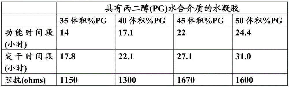
Table 4 shows that by varying the amount or ratio of propylene glycol in the hydration medium, the shelf life of the hydrogel tip can be adjusted to the desired indication. For example, if the nasal stimulator device is intended for single day use, it may be useful to include 35 volume percent (vol%) propylene glycol hydration medium to form a hydrogel tip. The hydrogels, whether they contain a hydrating agent or a hydrating medium, or whether they do not, may be sized, shaped, appropriately molded, etc. to form the electrical contacts of the nasal stimulator device. For example, the hydrogel may be included as part of the tip of the nasal stimulator device, typically at the tip of the tip. Although the use of hydration media in hydrogel tips for nasal or sinus stimulation has been described, it is understood that they may be used in hydrogels for other applications.
As described above, the electrically conductive hydrogel may be included in the prongs or tips of the nasal stimulator device and used to facilitate electrical connection between the nasal stimulator device and the nasal or sinus tissue. Some examples of nose stimulator device prongs or tips may be found in U.S. application serial No. 14/256,915 (U.S. publication No. 2014/0316485), entitled "NASAL STIMULATION DEVICES AND METHODS," filed 4/18/2014, the contents of which are incorporated herein by reference in their entirety (in U.S. application serial No. 14/256,915, the conductive hydrogel is referred to as a hydrogel electrode). The nasal stimulator device may be configured to include a disposable component that is removably attached to the reusable component or housing. Fig. 1 shows an exemplary disposable component. In this figure, the disposable unit (100) is made up of a pair of arms or prongs (102, 106) for receiving electrodes (not shown), the pair of arms or prongs (102, 106) being adjustable in the lateral direction and also being rotatable or swingable to change the angle between them. Each electrode is provided in the form of a metal rod encapsulated in a polymeric sleeve (104). Each sleeve (104) terminates at a slot (108, 110), the slot (108, 110) being filled with a conductive polymer (e.g., hydrogel) for making electrical contact between the electrode and nasal or sinus tissue.
Alternatively and as shown in fig. 2, the disposable unit (200) has a pair of arms or prongs (202, 204) containing an opaque polymer sleeve (206) for encapsulating an electrode (not shown). The opaque polymeric sleeve may be configured to completely cover the electrode or partially cover the electrode. In this variant, the sleeve (206) and the electrodes are made flexible and spring-like. Their flexibility is designed to accommodate variations in nose width and the angular orientation preferred by the individual user. Similar to fig. 1, a conductive hydrogel may be disposed at the tip of the prongs (202, 204) to act as an electrical contact between the electrode and the nasal or sinus tissue.
Figures 3A-3C provide exemplary configurations of electrically conductive hydrogels when used with nasal stimulation devices. Fig. 3 shows a polymer tube sleeve (300) as an opaque tube, which internally surrounds the support electrode. In this variant, the sleeve (300) terminates at a slot filled with a conductive polymer for providing an electrical connection between the electrode and the nasal or sinus tissue. As shown in the cross-sectional view of fig. 3B, the polymer (302) fills the slots (304) and forms a slightly protruding cylindrical surface for optimal contact with nasal tissue. It may be beneficial for the polymer to be compressible so that it conforms to the contours of the nasal cavity lined with the mucosa of squamous epithelium, which tissue then transforms into columnar respiratory epithelium. The cavity provides drainage to the sinuses and nasolacrimal duct, and thus presents a highly moist and moist environment (Anatomy of the human nose, Wikipedia). In the variant shown in fig. 3B, the conductive polymer forms a shell (306) around the end of the sleeve (300) filling the slot and extending the sleeve down to contact the electrode.
Method for producing electrically conductive hydrogels
The method for preparing a conductive hydrogel described herein generally comprises the steps of: mixing a first monomer, a second monomer, and a photoinitiator to produce a formulation, wherein the first monomer is an acrylate monomer; and irradiating the formulation with UV radiation to crosslink the formulation. The monomers may be those described above, for example, the monomers listed in table 1. In some variations, the electrically conductive hydrogel is crosslinked by covalent bonds. In other variations, the hydrogel is crosslinked by ionic bonds. In hydrogels with hydrophilic and hydrophobic regions, the hydrophobic regions may form a shell around the hydrophilic core, thereby forming a core-shell structure. A hydrogel with a high water content (e.g., 50% -70%) and having a hydrophobic shell may dry out more slowly than a hydrogel without a hydrophobic shell, and thus may retain its electrical conductivity for a longer period of time when left exposed to air between uses.
In some variations, the hydrogel may be surface modified to develop a relatively more hydrophilic surface to further reduce skin resistance when in contact with nasal tissue. Surface modification may be desirable for hydrogels that have developed a hydrophobic shell, causing its surface to become hydrophobic. In this application, a surface is generally considered hydrophobic if the water contact angle (sessile drop) exceeds 80 degrees, and hydrophilic if the contact angle is less than 30 degrees. Surface modification can be achieved in a number of ways. One method is to use a hydrogel formed by low pressure plasma treatment generated by RF discharge or microwave discharge. Suitable plasma materials include air, oxygen, and water vapor. It is believed that this method causes chemical modification of the molecules on the surface, thereby forming hydroxyl groups that render the surface hydrophobic. Another method is to deposit hydrophilic polymers by plasma polymerization, including plasma-assisted chemical vapor deposition (PACVD) or plasma-induced chemical vapor deposition (PICVD). Suitable materials to be deposited using a plasma polymerisation process include HEMA or GMA. Another surface modification method, which is suitable for hydrogels having siloxane groups on the surface (e.g. hydrogel SB5 described in examples 15-19 below), involves chemical activation of the surface, for example by treating the surface with aqueous sodium hydroxide (1-10% w/w), washing it to remove unreacted base, and then reacting it with a molecule terminated by hydroxyl or amino groups, such as polyethylene glycol. In another approach, surface modification may include the addition of surfactants to the hydrogel formulation that migrate to the surface upon polymerization. Surfactants are amphiphilic molecules that expose hydrophilic ends at the hydrogel surface. Exemplary surfactants include sodium lauryl sulfate, polyuronic acid salts, Triton X-80, and the like. Alternatively, the hydrogel surface may be modified, e.g., made more hydrophilic, by including a hydration medium into the formulation. Exemplary hydration media are described above.
The electrically conductive hydrogel formulation may be prepared to cure to a zero or low swelling solid formulated with a diluent at the same weight fraction as the equilibrium swelling ratio of the hydrogel when fully cured. The weight ratio between the diluent and the monomer and photoinitiator mixture may be from about 35% to about 70%. Exemplary diluents that can be used are listed in table 1. These diluents are water soluble, biocompatible and have a viscosity of less than 100CST at 25 ℃.
The curing process may be caused by any light having a suitable wavelength. In some variations, the curing process is induced by irradiation with UV light in the wavelength range of about 350nm to about 450nm, and is catalyzed with one or more photoinitiators selected from table 1. Other photoinitiators as described above may also be used. For example, acylphosphine oxides and bisacylphosphine oxides that are biocompatible and absorb long wavelength ultraviolet radiation may be used.
Table 5 provides an exemplary list of electrically conductive hydrogel formulations that are cured by irradiation with UV light in the wavelength range of 300-480nm, e.g. 350-450nm, at a temperature in the range of 10-65 deg.C, preferably 25-45 deg.C for 10 seconds to 30 minutes, e.g. 1-15 minutes, wherein 2,4, 6-trimethylbenzoyl-diphenylphosphine oxide (TMDPO) is used as photoinitiator.
Table 5: exemplary electrically conductive hydrogel formulations
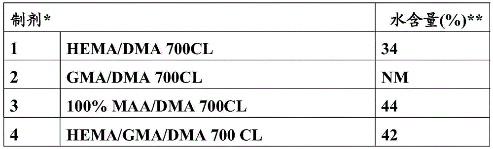

HEMA ═ hydroxyethyl methacrylate; DMA ═ dimethylacrylamide; GMA ═ glycerol monomethacrylate; MAA ═ methacrylic acid; DMAC ═ dimethylacetamide; BDDA ═ 1, 4-butanediol diacrylate; NVP ═ N-vinylpyrrolidone; MEMA ═ methoxyethyl methacrylate; HEMA10 ═ polyethoxy (10) ethyl methacrylate.
NM ═ was not measured.
Examples 1-7 and 15 provide other exemplary electrically conductive hydrogel formulations. Based on data from experiments using these hydrogel formulations, hydrogels with minimal increase in mass and height (i.e., swelling/swelling) while exhibiting high hydration can be used. The swelling caused by hydrogel swelling typically produces effects that may require balancing. For example, swelling enhances electrical conductivity, making the hydrogel more hydrophilic and therefore more comfortable when in contact with the skin and reduces contact resistance. However, more swelling also makes the hydrogel more viscous and less stable, and therefore more prone to breaking in current applications, and increases the drying rate (although the amount of water remaining after a particular drying period depends on both the drying rate and the initial water content). In view of these effects, exemplary formulations (e.g., formulations SB4A and SB4B) may include a diluent that is an inert solvent that forms a hydrogel that has a substantial swelling ratio (or water uptake) but does not swell when hydrated, because as the hydrogel hydrates and swells in water, incoming water displaces the diluent, leaving less volume change. For example, hydrogel formulations comprising silicone monomers terminated with acrylic acid provided in example 6 (hydrogel formulation SB4A) and example 7 (hydrogel formulation SB4B) may be useful. The SB4A and SB4B hydrogel formulations demonstrated that a high level of hydration was achieved with minimal swelling, as shown by the data provided in example 14. The silicone hydrogel formulation provided in example 15 (hydrogel formulation SB5) showed increased crosslinking due to the inclusion of trimethylolpropane trimethacrylate, exhibiting zero swelling, as shown by the data provided in example 18. In summary, the data provided in examples 16-19 illustrate that the SB5 formulation (SB5) is useful when formed as a hydrogel tip for a nasal stimulator device. Upon hydration, the swelling of the SB5 formulation was shown to be significantly less than earlier formulations (e.g., SB1 and SB2), and the boundary extending beyond the tip was less than 0.5mm when the hydrogel was fully hydrated. In addition, the resistance is less than 600 Ω, which is well within the required range, and after drying up to 8 hours, the resistance does not increase more than 1000 Ω. The results also show that the SB5 formulation was sufficiently extracted and hydrated after 12-24 hours of extraction in 55 ℃ saline to be ready for use. However, the hydrophobic nature of the surface increases the contact resistance, especially when in contact with parts of nasal tissue that have been particularly hydrated. This problem can be solved by hydrophilic surface modification or addition of a hydration medium, as described previously herein. Hydrogels that are capable of taking up high levels of water (i.e., are highly hydrated) are generally more electrically conductive. Parameters such as monomer extraction rate and electrical resistance can be measured and the resulting values used to indicate the degree of hydration of the hydrogel, as shown in examples 8-12, 16 and 17. As shown in example 9, the addition of diluent does not appear to affect the hydration of the hydrogel, but may affect the cure rate.
Manufacturing method
Various methods of manufacture are also described herein. These processes may include various ways of curing the hydrogel formulation, various ways of obtaining a suitable hydrogel shape, and various ways of assembling the hydrogel at the tip of the nasal stimulator. The manufacturing method may be used to form a hydrogel contact of the disposable bifurcated portion of the NASAL stimulator shown in fig. 2, or a hydrogel contact having an otherwise configured NASAL stimulator tip/tip, such as described in U.S. application serial No. 14/256,915 (U.S. publication No. 2014/0316485) entitled "NASAL stimuli devices AND METHODS", filed 4, 18, 2014, the contents of which were previously incorporated herein by reference in their entirety (the conductive hydrogel in U.S. application serial No. 14/256,915 is referred to as a hydrogel electrode). Generally, manufacturing methods that facilitate expandability and storage of the shaped hydrogel can be used. Furthermore, a manufacturing method that increases the volume of hydrogel at the electrode tip of the nasal stimulator may be beneficial as this will cause the hydrogel to dry less. It is also useful to adjust the manufacturing process so that the hydrogel forms a bulge on the distal end of the electrode of the nasal stimulator.
In one variation of the cured hydrogel formulation, a disposable mold is used, such as that shown in fig. 4. The disposable mold forms a continuous shell of the conductive hydrogel formulation around the circumference of the tube sleeve while filling the slots just proximal to the electrodes and the spaces within the tube sleeve. As shown in the figure, the tube may be made of a low cost and biocompatible processable material transparent to UV radiation, such as polyethylene, polyvinylidene fluoride (PVDF), polypropylene (non-UV absorbing grades), polystyrene, ABS, etc. The tube is typically open at one end and closed at the other end, and may have an internal diameter of about 6.0mm, a length of about 14mm, and a wall thickness in the range of about 0.20 to about 1.0 mm. Other variations of the tube may have an inner diameter in the range of about 3.0mm to about 10mm and a length in the range of about 5.0mm to about 20 mm.
The disposable mold can be injection molded immediately as it is used in the curing process. As shown in fig. 5, the exemplary assembly and curing process may track the transport components and subassemblies and remotely locate them. In this process, electrodes shaped as rods, springs or foils are assembled into a separately molded tube sleeve. The pre-assembled electrode and shroud assemblies may be stocked and provided to the final assembly process shown in fig. 5, or they may be assembled in-line, as shown in fig. 5.
The conductive hydrogel formulation may be contained in an opaque, air-tight sealed container. The formulation may also be degassed prior to being loaded into the container. In some variations, the disposable molds are injection molded in-line and stored in inventory for processing. Long term storage of the disposable moulds is preferably avoided, as long term storage introduces dust particles into the moulds, and then the disposable moulds will require cleaning or rinsing before use. Next, the electrode subassembly is placed within a disposable mold, and a specific volume of the hydrogel formulation is discharged into the disposable mold. The disposable mold is then moved to a station where the irradiation source is placed so that uniform irradiation is provided on all sides of the disposable mold. The temperature is controlled by flowing nitrogen through the station, which also maintains the curing mixture in an oxygen-free environment. In this case, the curing temperature ranges from 30 to 45 ℃, and the curing time ranges from about 1 minute to about 15 minutes. The subassembly is then removed from the disposable mold and the disposable mold is discarded after curing is complete.
In some variants, demolding may be achieved by applying a rapid cooling pulse, for example by simple immersion in water at 0 ℃. The electrode subassembly comprising the hydrogel shell may then be immersed in deionized water for a period of 2-24 hours in order to remove unreacted monomers and diluents. The temperature of the deionized water may range from about 35 ℃ to about 50 ℃ or from about 10 ℃ to about 40 ℃. The electrode subassembly, also known as a disposable unit, is then removed from the water, simply dried to remove excess water, and then packaged in a sealed pouch for sterilization.
Additional manufacturing methods for forming the hydrogel into a suitable shape for use with a nasal stimulator device are also described herein. Some variations of this method include dip coating and spraying techniques. For example, the tip of the nose stimulator's tip (800) may be repeatedly dipped up and down (in the direction of the arrow) in hydrogel (802), as shown in fig. 8A; or using a sharp tip at an angle to scoop the hydrogel (802), as shown in fig. 8B. Here, the viscosity of the hydrogel may be adjusted such that after dipping or scooping, the cavity (804) within the tip (800) is filled with hydrogel. Additionally, a substrate may be included in the hydrogel formulation to aid in attaching the hydrogel to the tip upon dipping or scooping. The thickness of the hydrogel can be controlled by such factors as the rate of rise/fall of the tip during dipping or scooping, the temperature and/or the viscosity of the hydrogel. The viscosity of the hydrogel can be adjusted to be high enough to allow shape memory prior to final curing. After dip coating by dipping or scooping, the curing of the hydrogel on the tip can be done using UV light (as described above) or by thermal methods. It should be understood that multiple dipping/curing cycles may be implemented. One or more portions of the hydrogel tip may then be masked so that an insulating layer (806) can be applied over the hydrogel tip (800), e.g., by spraying or adhering, to cover and insulate those portions of the tip (800) not intended to be electrically conductive, as shown in fig. 8C. The insulating layer may comprise any suitable insulator, such as a non-conductive polymer. After the insulator is applied, for example by spraying or adhering, the masked portion (808) of the tip (800) will be conductive. Alternatively, when no mask is used, the orientation of the hydrogel tip can be controlled so that only the insulating region is sprayed or exposed.
The hydrogel may be first shaped and then placed on the end of the conductor, such as the tip of a nose stimulator tip. Using these methods, shaped hydrogel portions can be prepared in advance, then hydrated in bulk and/or purged in bulk of excess diluent and/or excess unreacted monomer, stored as a hydrogel/conductor subassembly prior to hydration or stored in hydration (i.e., by remaining in saline solution).
The shaping of the hydrogel may be achieved in any suitable manner. In one variation, the hydrogel formulation is poured into a tray and then the conductors are placed in the formulation. The formulation is then cured to form a hydrogel sheet, and cut using a laser cutter, die cutter, blade to shape the sheet. The cut hydrogel may be referred to as a hydrogel preform. The cured hydrogel can also be shaped to include a convex shape, if desired. Alternatively, the hydrogel formulation may be poured into a tray that includes a separate mold or cavity having a desired shape, such as a protrusion. The hydrogel shape formed by a separate mold or cavity may also be referred to as a hydrogel preform. In some cases, cutting and molding may be used in a combination manner, where the hydrogel is cut into molded preforms.
More specifically and as shown in fig. 9A-9I, the hydrogel mixture (1) is first poured into the tray (2). As shown in fig. 9B, the tray (2) may be configured to include a separate mold or cavity (3) into which the hydrogel (1) is to be poured. The conductor (4) may then be placed inside the hydrogel (1) before curing. The conductors may have any suitable form and may be made of any suitable electrically conductive material. For example and as shown in fig. 9C, the conductor may be configured as a metal strip (5) with a hole (7), a coil spring (6), or a wire bent/shaped into, for example, a loop (8), or the like. These conductor configurations can be used to create a mechanical lock between the hydrogel and the conductor. In some cases, the metal strip (5) is configured without holes.
Placing the conductor in the hydrogel formulation may include using a locating or catching feature. The locating and catching features may also aid in the insertion of the conductor into the hydrogel to a desired depth. For example, as shown in fig. 9D, the end of the conductor (4) may be placed on a tray with the aid of a locating feature configured as a peg (9) or recess (10). The ends of the conductor (4) may also be placed with the aid of a catch feature such as a plate (11) provided above the tray (2), as shown in fig. 9E. In these cases, the plate (11) may be configured to capture the conductor, based on the geometry of the conductor, for example the conductor may have a larger section (12) at one of its ends, a section (13) that bends/deforms, or a clamping or interference fit (14) with the plate (11). After placing the conductor in the hydrogel, the hydrogel is cured according to any of the methods described herein. When the hydrogel is molded/cured into a sheet, the hydrogel may then be formed into a desired shape, such as by a laser cutter, die cutter, blade, or the like. The part produced by forming (element 16 in fig. 9G) can be referred to as a conductor-hydrogel subassembly (element 17 in fig. 9G), whether by cutting or molding.
As shown in fig. 9G, the conductor-hydrogel subassembly (17) may then be hydrated and stored in an aqueous environment until further assembly of the tip for the nasal stimulator device, or it may be stored dry for subsequent processing. According to a variant, as shown in fig. 9H, assembling the conductor-hydrogel subassembly (17) into the molded part (20) to produce the desired final tip assembly may include lowering the subassembly (17) into the hollow shaft (21) of the molded part (20) such that the hydrogel (16) rests on the stepped portion (22) inside the shaft (21). Here, the conductor (4) may be bent/deformed at a location where it leaves the shaft (21), thereby creating a mechanical lock, for example, between the subassembly (17) and the molded part (20). Referring to fig. 9I, the top cover (24) may also be included as part of the molded portion (20), via, for example, a hinge-like mechanism (23).
For example, the hydrogel can also be incorporated into the nose stimulator device tip by controlled dispensing of the hydrogel formulation directly into the cavity of the tip assembly, for example, by Computer Numerical Control (CNC) or robotics or by manual control. Controlled dispensing may be achieved by a tilting mechanism that ensures vertical alignment of the windows or the use of a guide, but is not limited to such. It should be understood that other suitable controlled dispensing processes may be used. Controlled dispensing can be used to control the size of the projections of the hydrogel tip.
In one variation, the tilt during dispensing can be used to control the introduction of the hydrogel into the tip of the device. For example, as shown in fig. 10A, tip portion (25) may be angled during dispensing of hydrogel formulation (26) from dispenser device (28). The amount of tilt may vary and may range from about 5 degrees to about 45 degrees. The amount of tilt may be determined by the geometry of the window to be filled. Generally, the nasal stimulator device will be tilted such that the walls of the window are equidistant about the vertical centerline of the opening, thereby allowing gravity to equally dispense the liquid hydrogel formulation. For example, if the centerline of the window being filled is at 45 degrees to the centerline, the nose stimulator device is tilted (rotated) 45 degrees. Tilting can generally be achieved by using tilting mechanisms such as pins, rollers and/or plates. Fig. 10B shows how the tip portion (25) is tilted using the displacement roller (27) after the hydrogel formulation is dispensed and cured. After dispensing the hydrogel formulation to one tip of the tip portions (25), the formulation is solidified and the displacement roller (27) moves to tilt the tip portions (25) in the opposite direction. The tilting mechanism typically tilts the fixture (e.g., a flat surface such as a plate) when placing the tip portion to expose each cavity to the dispenser because the cavities are inward facing in the normal orientation (when the tip portion is placed on the fixture) and the opening in the tip portion should face in an upward direction for dispensing. In some cases, the fixation device may also have alignment pins that complement holes provided in the base portion of the nose stimulator.
One or several tip portions may be inclined during dispensing. For example, as shown in fig. 10C, the hydrogel dispenser (28) includes a plurality of dispenser tips (29) and a plurality of tip portions (25) disposed on a plate (30). A slip sheet (not shown) coupled to the plurality of rollers (31) may be used to tilt the plurality of tip portions (25). The plate (30) can also be moved back and forth in the direction of the arrow to effect a rocking/tilting motion.
In another variation, one or more guides disposed in or on a portion of the tip portion may be used to control the dispensing of the hydrogel by enabling the tip portion to tilt or flex so that the cavity is substantially perpendicular to the hydrogel dispenser. The guide may be a rail and/or a groove/slit that interfaces with a corresponding or bonded structure on the fixture, reversibly attaching the tip portion to the fixture and tilting or flexing the tip portion to allow the cavity to be filled. For example, as shown in fig. 11A-11C, a slot (32) may be provided in the tip portion (33) (fig. 11A), a track or slit (34) may be provided within the lumen (35) of the tip portion (33) or on the outer surface (36) of the tip portion (33) (fig. 11B), or a slot (37) may be provided in the tip (38) of the tip portion (33), similar to a lock and key combination (fig. 11C).
In yet another variation, the hydrogel of the tip portion may be shaped using a casting process. Here, the hydrogel formulation is poured into a mold containing a hollow cavity of the desired shape, and then allowed to cure. Some variations of the mold may be constructed as shown in fig. 12A. Referring to this figure, the mold (39) includes a base block (44), a wobble plate (42), screws (43), and compression springs (45). The substrate block (44) includes one or more casting surfaces (41) (i.e., convex casting surfaces) configured to form a protrusion in the hydrogel tip. The convex casting surface will typically have the same radius as the distal end of the tip portion (see element 48 in fig. 12B) and include a depression, such as depression (40) for creating a protrusion during casting. Using a screwdriver (43) and a compression spring (45), the wobble plate (42) compresses and secures the tip portion (see fig. 12C) to the base block (44). The wobble plate may be made of a material that transmits UV light, such as an acrylic material. The height of the screws (43) can be adjusted to control the amount of compression imparted by the plate (42). More specifically, as shown in fig. 12B-12D, the operation of manufacturing the hydrogel tip by casting may include: a bifurcated disposable tip (46) is provided having a window (47), and the distal end (48) is oriented so that the window (47) faces the casting surface (41) of the substrate block (44) of the mold (39) (fig. 12B). The distal end (48) of the bifurcated tip (46) is then secured to the base block (44) by tightening the screw (43), causing the wobble plate (42) to compress against the base block (44) (fig. 12C). Likewise, the tip (46) is loaded into a mold having a window facing the casting surface. The UV curable hydrogel formulation described herein may then be injected through a channel (49) in the disposable tip (46), which channel (49) is fluidly connected to the distal end (48) in a manner that delivers the hydrogel to the window and casting surface (fig. 12C). As described above, the casting surface includes recesses for forming projections in the hydrogel. After the hydrogel formulation is injected into the tip portion (46), UV light may be applied to cure the hydrogel. The wobble plate or the substrate block can be made of a material that is transmissive to UV light. Exemplary UV transmissive materials include glass. Here, UV light can be transmitted through the substrate block (44) and the distal end (48). The wobble plate (42) is then released, thereby allowing the distal end (48) to be removed from the base block (44). As shown in FIG. 12D, the hydrogel formed by the casting process has protrusions (50) protruding from the windows (47). While a single mold is shown in fig. 12A-12D, it is to be understood that sets of arrays of molds can be constructed and used for mass production.
Some manufacturing methods include reducing the wall thickness at the tip end of the tip portion, thereby causing an increase in the volume of hydrogel in the tip portion. In one variation, this may be accomplished by molding the tip from a single piece and using a micro-molding process and materials. Using this process, for example, the wall thickness of the tip portion may be reduced from thickness a (between the left arrows) to thickness B (between the right arrows) in fig. 13, thereby increasing the volume within the tip end. Other methods may include steps that result in a high volume to surface ratio, thereby maintaining a desired degree of hydrogel hydration.
Tip assembling method
Further described herein are methods for assembling the tip portion of a nasal stimulator device. These assembly methods may be mixed and matched with the various ways of shaping the hydrogel described above. The method may also be used to assemble the disposable tip portion shown in fig. 2 or tip portions having other configurations. Some variations of the tip portion may require only a component prior to adding the hydrogel to the tip portion. Generally, the assembly method includes securing the hydrogel within the tip portion mechanically (e.g., by hydration after placing the hydrogel into the tip, interference fit, threaded fit, etc.) or chemically (e.g., by epoxy, bio-adhesive, ultrasound, etc.).
In a variation where the hydrogel formulation is dispensed into the window of the tip portion, the tip may include an electrode (51) having a distal end (59) molded into the cap (52) and a flexible frangible or spring-like proximal end (60) including an arm (61), as shown in fig. 14A. The electrode (51) may include a slot (53) for mechanically retaining the hydrogel within the cavity (element 54 in fig. 14B) of the tip assembly (element 55 in fig. 14B). As shown in fig. 14B, in its partially assembled state, the hydrogel may be injected into the cavity (54) via the window (56) using the dispensing system and method described above. Here, the formation of hydrogel projections can be controlled by the surface tension and/or viscosity of the uncured hydrogel.
After the hydrogel is cured, the tip assembly may be attached to a nasal stimulator device, as shown in fig. 14C. Referring to fig. 14C, the tip assembly (55) is attached to the remainder of the disposable tip portion via a holder block (57) located at the distal end of the bent tube (58) (within the tip of the stimulator device), said bent tube (58) having a tip holder (62b) with a sloped surface (62). The electrode (51) of the tip assembly (55) is pushed in the direction of the arrow so that it is forced to follow the sloped surface (62). When fully inserted to substantially surround the tip holder (62b), the flexible/frangible nature of the electrode arms (61) allows them to quickly retract to their original configuration. When pulled upward in the direction of the arrow and disengaged from the tip holder (62b), the electrode arm (61) may be configured to permanently deform, so that the tip assembly cannot be used again, as shown in fig. 14D.
In a variation where the hydrogel is preformed using, for example, any of the methods described above, the hydrogel may be preformed into a cylinder (63) having a slot (64) for receiving an electrode (65), as shown in fig. 15A. Here, the hydrogel is an unhydrated preform that is hydrated after the tip assembly is fully assembled. It is understood that the hydrogel preform may or may not be washed of excess unreacted monomer prior to integration into the tip assembly. During hydration, the hydrogel preform (63) swells, generally in the direction of the arrow, filling the open space and expanding through the window (66) to create a stimulating (contact) surface (67). Furthermore, if the gap between the electrode (65) and the slot (64) is small, the electrode is typically in full contact with the hydrogel during the initial stages of hydration (e.g., at 20% hydration). This is a beneficial safety feature as it ensures that the entire surface of the electrode is carrying current when the patient is using the nasal stimulator device. An angled slot (68) on the exterior of the tip assembly, opposite the window (66), may be used to align and mate the tip assembly with corresponding structure in the dispense cartridge during manufacturing, as described further below.
In other variations, the hydrogel preform may be placed in a tip assembly that includes a hinge, such as a living hinge. For example, as shown in fig. 16A, the tip assembly (69) may be configured to include a first side (70) having a cavity (77a) for placement of a hydrogel preform (not shown), a window (71) allowing expansion of the hydrogel preform, a channel (72) for slidable integration into an electrode (not shown), and an aperture (73). The first side (70) is coupled to the second side (74) via a living hinge (75). The second side (74) includes a cavity (77b), a tapered protrusion (76) received by the aperture (73) when the second side (74) is folded to contact the first side (70) at the living hinge (75). The conical projections (76) and holes (73) have an interference fit and may be welded together prior to hydration of the hydrogel preform. In another example, the tip assembly may include a deflectable electrode (78), the deflectable electrode (78) being deflectable in the direction of the arrow to allow the hydrogel preform (79) to be installed in the tip assembly, as shown in fig. 16B. Here, the electrode includes an aperture (73), the aperture (73) for receiving a tapered protrusion (76) when the first side (70) and the second side (74) are rotated at a living hinge (75) to close the sides together. In addition to the tapered protrusions and holes, tongue and groove configurations may also be used to secure the sides together. For example, as shown in fig. 16C, the female tapered groove (80) may be configured to have an interference fit with the male tapered tongue (81). Other variations of the tip assembly are as shown in fig. 16D and include a hydrogel retention strip (82) to help secure the hydrogel within the tip and/or a living hinge (84) recessed within a slot (83) provided in the tip surface to help prevent abrasion of nasal tissue.
The manufacturing method may also use a dispense cassette to assemble the tip assemblies in batches. Bulk packaging can reduce packaging materials and bulk, which is convenient for the end user. An exemplary dispensing cartridge is shown in fig. 17A-17E. Referring to fig. 17A, a dispense cartridge (90) may include a cartridge housing (85) having a proximal end (86) and a distal end (87), and an alignment block (88) coupled to the proximal end (86), and a constant force spring (89). A plurality of tip assemblies (91) may be stored in the cartridge housing (85) and held in place by constant force springs (89), which constant force springs (89) urge the tips (91) against the alignment block (88). A plurality of holes (93) are provided in the constant force spring (89), the plurality of holes (93) being spaced apart by a distance equal to the length of one tip assembly (91). When the dispenser box (90) is at rest, the pins (92) of the alignment block (88) do not engage the holes (93) in the constant force spring (89). As shown in more detail in fig. 17B, when the cartridge is at rest, the spring (94) in its unrestrained state pushes the pin (92) out of the hole (93) of the constant force spring (89), and the constant force spring (89) pushes the tip (91) (see fig. 17A) back toward the surface (95) of the alignment block (88). When the dispenser cartridge is activated by the user for attaching the tip (91) to the remainder of the nasal stimulator device (not shown), as shown in fig. 17C, the alignment block (88) is depressed to compress the spring (94) and allow engagement of the pin (92) with the constant force spring hole (93), thereby releasing the load provided by the constant force spring (89) to the tip (91) while the tip is attached. A wick (96) may also be provided to maintain a supply of moisture in the cartridge so that the hydrogel in the tip (91) does not dry prematurely. The wick (96) may be saturated with a fluid, such as saline. As previously described, the tip assembly may include a slot (97) (shown in fig. 17D), the slot (97) being configured to engage a complementary structure of the cartridge housing (99) so that the angular alignment of the electrodes may be controlled. For example, as shown in fig. 17E, a slot (97) in the tip (91) engages a rib (98) of the cartridge housing (99).
Some variations of the manufacturing method combine the electrode and tip holder shown in fig. 14C with the dispense cartridge shown in fig. 17A-17C, as shown in fig. 18A-18D. First, the alignment block (88) is depressed in the direction of the arrow (fig. 18A) to expose a new tip assembly (91), which new tip assembly (91) is accessible through the bifurcated portion (101) of the nose stimulator device (103) (fig. 18B). The electrode (105) is aligned for attachment to a connector (not shown) in the tip (101). Next, the device (103) and tip (101) are advanced through the access hole (107) in the alignment block (88) until the tip (not shown) is attached as shown in fig. 14C. After attachment, the device (103) may be withdrawn from the alignment block (88), and the compressive force on the alignment block (88) may be released in the direction of the arrow, as shown in fig. 18D.
If tip detachment is desired, a tip removal tool may be used, as shown in FIGS. 19A-19C. Referring to fig. 19A, the tip assembly (91) may be inserted into a cavity (111) of a tip removal tool (113) similar to a retaining ring. The removal tool (113) may then be compressed to compress the tip assembly (91) within the removal tool (113), as shown in fig. 19B. While maintaining the compressive force, the device (103) may be pulled away from the tip removal tool (113) to disengage the device (103) from the tip assembly (91), as shown in fig. 19C.
In a further variant, the manufacturing method comprises the step of attaching the flexible base unit to the rigid tip assembly. For example, as shown in fig. 20A, a cap (115) may be provided over the hydrogel preform (117). A rigid elongate electrode (119) may extend from the top cover (115) to advance through the flexible base (121). A segment (123) comprising a window (125) is attached to the flexible base (121). As shown, the segment (123) has an open top (127) so that the hydrogel preform (117) can be loaded therein. After the electrode (119) is advanced into the flexible base (121), the cap (115) may be secured to the flexible base, such as by welding. In another example, as shown in fig. 20B, the flexible base (121) is configured to include a tapered end (129) for receiving a complementary structure (131) proximate the distal end (133) of the elongated electrode (119).
Application method
Also described herein are methods for stimulating nasal or sinus tissue (and lacrimal glands). In one variation, the method includes placing an arm of a nasal stimulator device against nasal or sinus tissue, the arm having a distal end and a conductive hydrogel disposed at the distal end; and activating the nasal stimulator device to provide electrical stimulation to the nasal or sinus tissue, wherein the electrically conductive hydrogel is used to facilitate an electrical connection between the nasal stimulator device and the nasal or sinus tissue. As described above, the electrically conductive hydrogel may comprise a first monomer; a second monomer; and a photoinitiator, wherein the first monomer is an acrylate monomer, and the electrically conductive hydrogel has one or more characteristics that make it suitable for use with a nasal stimulator device. The conductive hydrogel may include monomers, diluents, photoinitiators, and other components as described herein, such as those listed in tables 1 and 3. Also, these formulations were subjected to UV irradiation to form crosslinked conductive hydrogels. The conductive hydrogels used in these methods may include those listed in tables 2 and 5.
Typically, the lachrymal response is activated by the nasolacrimal reflex when one or more nasal or sinus afferents (trigeminal afferents as opposed to olfactory afferents) are stimulated. This stimulation may be used to treat various forms of dry eye, including (but not limited to) chronic dry eye, intermittent dry eye, seasonal dry eye. To continuously alleviate dry eye symptoms, nasolachrymal irritation may be required one to five times per day. In some cases, the stimulus may be used as a prophylactic measure to treat users who may be at increased risk of developing dry eye, such as patients who have undergone eye surgery, such as refractive vision correction and cataract surgery. In other cases, the stimulus may be used to treat ocular allergies. For example, an increase in tears may wash allergens and other inflammatory mediators out of the eye. In some cases, the stimulation may be configured to induce habituation of neural pathways activated during an allergic reaction (e.g., by continuously delivering a stimulation signal for an extended period of time). This may lead to habituation of the reflex, which may inhibit the usual reaction that the user has with allergens.
Examples
The following examples are intended to further illustrate the electrically conductive hydrogel formulations disclosed herein and should not be construed in any way as limiting their scope.
Example 1: method of making electrically conductive hydrogel for use with nasal stimulator device
The first monomer, second monomer and photoinitiator were added to a round bottom flask wrapped in aluminum foil and equipped with a magnetic stir bar. Additional monomers (e.g., a third or fourth type of monomer, etc.) and/or diluents may also be added. The flask was clamped on top of a magnetic stirrer/heater equipped with a nitrogen purge line. After the magnetic stirrer and nitrogen purge were activated, the contents of the flask were mixed for five minutes to form a monomer mixture. While mixing the monomers, a sleeve of the nasal device (such as sleeve (300) shown in fig. 3A-3C) is inserted into a disposable mold (such as shown in fig. 4) having a window or louver that opens to allow UV light to enter. The pipe sleeve should be oriented vertically within the mold. Next, the monomer mixture was drawn into the syringe from the flask and the syringe was covered with foil. A needle, such as a 30 gauge blunt needle, is attached to the syringe. The needle is inserted into the tube sleeve and the tube sleeve is filled with the monomer mixture. Next, the vent window was opened and the mold was irradiated with UV light for about three minutes. Then, the mold was rotated horizontally with the louver facing upward, and the mold was irradiated with UV light for about seven minutes. The mold is cooled and then the sleeve is removed from the mold.
Example 2: preparation of a Silicone hydrogel comprising Methacryloxypropyltris (trimethoxysiloxy) silane and a methanol Diluent
The following were added to a round bottom flask wrapped in aluminum foil and equipped with a magnetic stir bar:
EGMDA (ethylene glycol dimethacrylate) (0.081g)
NVP (N-vinylpyrrolidone) (2.179g)
GMA (glyceryl monomethacrylate) (1.112g)
DMA (dimethylacrylamide) (3.917g)
Methacryloxypropyltris (trimethoxysiloxy) silane (2.712g)
Lucirin(TPO)(0.081g)
Methanol (2.88g)
The flask was clamped on top of a magnetic stirrer/heater equipped with a nitrogen purge line. The contents of the flask were then mixed for five minutes to form a monomer mixture. While mixing the monomers, the nasal device cuff and disposable mold were prepared as described in example 1. The monomer mixture was then drawn into a syringe, injected into a cannula and irradiated as described in example 1. The mold is cooled and then the sleeve is removed from the mold.
Example 3: silicone hydrogel SB1
A silicone hydrogel formulation SB1 was prepared and molded into a tube sleeve as described in example 1. The components of the SB1 hydrogel are provided below. The diluent was not included in the SB1 hydrogel formulation.

Example 4: silicone hydrogel SB2
Silicone hydrogel SB2 was prepared as described in example 1. The components of the SB2 hydrogel are provided below. A methanol diluent was included in the SB2 hydrogel formulation.
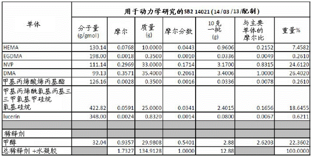
Example 5: silicone hydrogel SB3
A silicone hydrogel SB3 was prepared and molded into a tube sleeve as described in example 1. The components of the SB3 hydrogel are provided below. The SB3 hydrogel formulation included a methanol diluent and the HEMA monomer was replaced with EGDMA monomer, which was more hydrophilic than HEMA monomer.
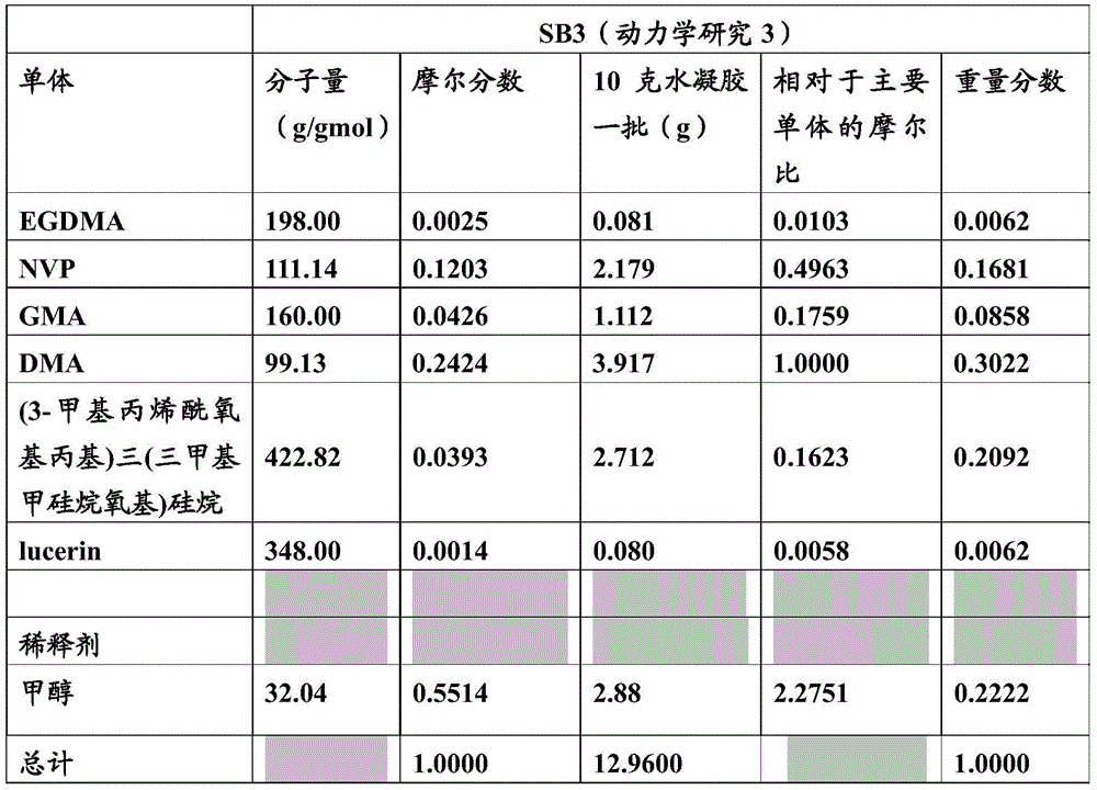
Example 6: silicone hydrogel SB4A
Silicone hydrogel SB4A was prepared and molded into a tube sleeve as described in example 1. The components of the SB4A hydrogel are provided below. The SB4A hydrogel formulation included a methanol diluent and two different acrylic-terminated siloxane monomers.

Example 7: silicone hydrogel SB4B
Silicone hydrogel SB4B was prepared and molded into a tube sleeve as described in example 1. The components of the SB4B hydrogel are provided below. The SB4 hydrogel formulation also included a methanol diluent and two different acrylic-terminated siloxane monomers.
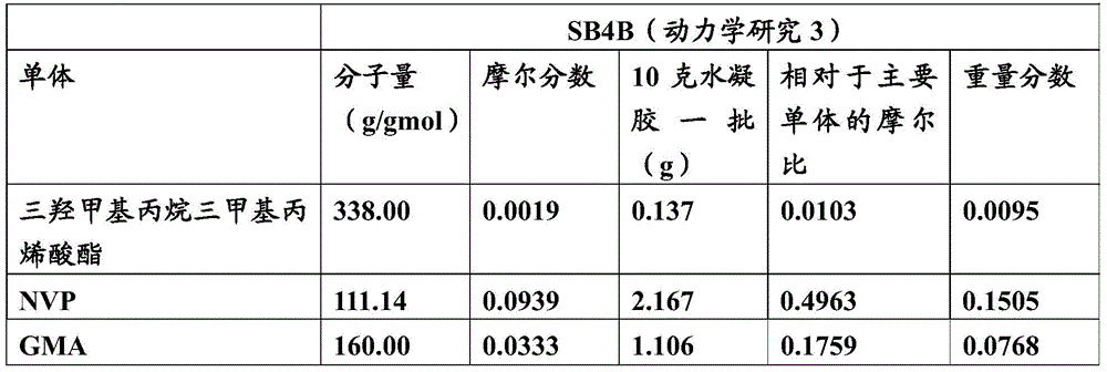
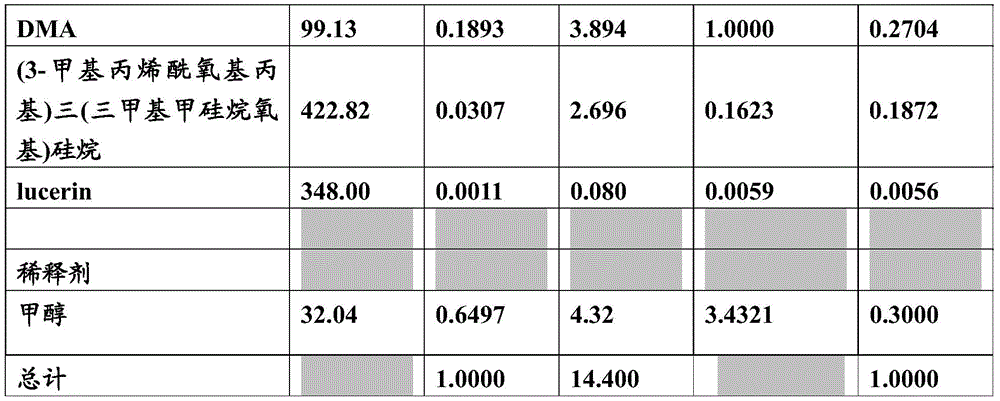
Example 8: detection of hydration of SB1 hydrogel as a function of monomer extraction Rate
After curing, the hydration of the SB1 hydrogel formulation was examined as a function of the extraction rate of unreacted DMA and NVP monomers, as shown below. The formulation was immersed in saline (NaCl in deionized water, 0.9% w/w) using 3.5mL of saline per tube sleeve, each tube sleeve containing about 60mg of polymer. The temperature was kept constant at 55 ℃ and the solution was shaken in an incubation shaker at a speed of 100 rpm. The extraction was performed at 1,2, 3, 4,6, 8, 12 and 24 hours, with the saline extract being replaced with fresh saline solution after each time period. The extraction process removes unreacted impurities from the polymer and also allows hydration to occur. It is believed that the resistance depends on the degree of hydration of the polymer.
The extracts were analyzed by GC-MS chromatography using an Agilent 5975C mass selective quadrupole detector on an Agilent 7890A GC and monitoring for N-vinyl pyrrolidone (NVP), Dimethylacrylamide (DMA). Total ion chromatogram recordings were recorded at each elution and peaks were confirmed using pure NVP, DMA and methanol as references.
After about 1 hour of extraction (the terms extraction and hydration are used interchangeably herein), the extraction rate of the SB1 hydrogel formulation was about 170 μ g/h for DMA (as shown in fig. 21A); and the extraction rate of the SB1 hydrogel formulation was about 450 μ g/h for NVP (as shown in fig. 21B).
Example 9: detection of hydration of SB2 hydrogel as a function of monomer extraction Rate
After curing, the hydration of the SB2 hydrogel formulation was examined as a function of the extraction rate of unreacted NVP monomer, as shown in fig. 22A, and as described in example 8; and detected as a function of the extraction rate of methanol, as shown in fig. 22B. About 1 hour after curing, the extraction rate for the SB2 hydrogel formulation was about 1150 μ g/hr for NVP, which is much higher than the rate obtained using the SB1 hydrogel formulation. As described above, the difference between the SB1 and SB2 formulations was that SB2 contained a methanol diluent. The presence of diluent significantly increased the rate of extraction of unreacted monomer from SB2, as shown by the relative rates of NVP extraction from SB2 and SB1 (1,150. mu.g/h vs. 450. mu.g/h). However, the presence of the diluent also reduced the cure rate of SB2 relative to SB1 by reducing the effective mole fraction of each monomer (data not shown).
Example 10: detection of hydration of SB1 and SB2 hydrogels as a function of resistance
After curing, the hydration of the SB1 and SB2 hydrogel formulations was examined as a function of the electrical resistance over a 72 hour extraction period (monomer extraction is a process that helps complete the hydration of the hydrogel). The resistance was measured using a multimeter set to a series resistance mode reading. One pen of the multimeter is in contact with the spring of the reference cuff and the other pen is in contact with the spring of the test cuff. Resistance measurements were taken within 30 seconds. The resistance of the circuit, i.e. the resistance outside the test socket, was estimated to be 2k omega. The "pipe sleeve resistance" used in the examples means the resistance value for the pipe sleeve, i.e. 2k Ω are planed off.
From the data provided in figures 23A and 23B, it is shown that the resistance after the first hour of hydration/extraction is higher for both hydrogel formulations (about 145k Ω to 175k Ω), but the resistance drops as the hydrogels become more hydrated (i.e., they become more conductive). After 8 hours of hydration, data were not plotted considering the values were very low.
Example 11: detection of hydration of SB2 and SB3 hydrogels as a function of resistance
After curing, the hydration of the SB2 and SB3 hydrogel formulations was tested as a function of electrical resistance over a period of 1-8 hours and a period of 4-72 hours, as described in example 10. The data provided in fig. 24A and 24B show that hydration continues over a longer period of time (72 hours here). After 8 hours of hydration, these hydrogels were still usable (they were still conductive). Furthermore, the gel quality of SB3 was significantly higher than that of SB2 after hydration. It should be noted that while the gel quality of SB3 was higher than that of SB2, the gel height of SB3 was lower. This is due to the presence of the diluent.
Example 12: detection of hydration of SB4A and SB4B hydrogels as a function of resistance
After curing, the hydration of the SB4A and SB4B hydrogel formulations was tested as a function of resistance over a period of 144 hours. The data provided in fig. 25 also shows that the hydrogel remains hydrated for a longer period of time and becomes more conductive as hydration increases.
Example 13: SB2 and SB3 hydrogel swelling due to hydration
The mass and height of the SB2 and SB3 hydrogel casts were measured to determine the swelling of the hydrogels as a function of hydration. The measurements are provided in fig. 26A and 26B. The use of EGDMA monomer instead of HEMA monomer in SB3 made it more hydrophilic, resulting in increased water uptake and therefore greater mass compared to SB 2.
Example 14: swelling of SB4A and SB4B hydrogels due to hydration
The mass and height of the SB4A and SB4B hydrogels were measured and compared to the mass and height of the SB3 hydrogel to determine the swelling of the hydrogels as a function of hydration, as shown in fig. 27A and 27B. The SB4A and SB4B hydrogels that exhibited high hydration levels (see example 12) expanded less than the more hydrophilic SB3 hydrogels. Thus, higher conductivities were achieved with SB4A and SB4B hydrogels, while swelling/swelling was less.
Example 15: silicone hydrogel SB5
A silicone hydrogel formulation SB5 was prepared and molded into a tube sleeve as described in example 1. The components of the SB5 hydrogel are provided below. A methanol diluent was included in the SB5 hydrogel formulation.

In the SB5 formulation, diphenyl (2,4, 6-trimethylbenzoyl) phosphine oxide (CAS # 7598060-8, Lucirin TPO) was chosen as the UV initiator because it can be activated by UV radiation in the wavelength range of 400-450nm, and the pipe sleeve material (Versaflex OM3060-1, styrene-ethylene/butylene-styrene copolymer) is able to transmit bands in this range. The addition of trimethylolpropane trimethacrylate enhances the crosslink density and makes the mixture more resistant to drying.
Example 16: detection of hydration of SB5 hydrogel as a function of monomer extraction
After curing, the hydration of the SB5 hydrogel was examined as a function of the extraction rate of unreacted DMA and NVP monomers and methanol, as shown in fig. 28A-28C and similar to that described in example 8. Briefly, the extracts were analyzed by GC-MS chromatography using an Agilent 5975C mass selective quadrupole detector on an Agilent 7890A GC and monitoring for N-vinyl pyrrolidone (NVP), Dimethylacrylamide (DMA) and methanol (MeOH). Total ion chromatogram recordings were recorded at each elution and peaks were confirmed using pure NVP, DMA and methanol as references. The data presented in fig. 28A-28C show that the extraction rate of methanol is fastest, followed by DMA. NVP extraction is slowest. The extraction rate depends only on the solubility of each substance in saline at the hydration temperature (55 ℃), since the swelling of the hydrogel network is the same in all cases. As shown in the figure, after 24 hours of hydration, the extraction rate of all substances appeared to reach a low plateau. Based on these results, it was concluded that after 24 hours of hydration, the SB5 hydrogel was ready for use.
Example 17: detection of hydration of SB5 hydrogel as a function of resistance
After curing, the hydration of the SB5 hydrogel formulation was tested as a function of electrical resistance in extractions of different time periods, similar to those described in examples 10-12. As shown in fig. 29, upon hydration induced by extraction using brine, the resistance dropped significantly. The electrical resistance of the SB5 hydrogel reached a level greater than 0.6k Ω after 12 hours of extraction and reached a lower plateau after about 24 hours of extraction.
Example 18: swelling of SB5 hydrogel due to hydration
Measuring SB5 WaterThe mass and height (swelling) of the gel casting, determining the swelling of the hydrogel as a function of hydration (and extraction time period). Referring to the data table in fig. 30A, the percent hydration of SB5(42-05) (defined as 100 (M) at 48 hours was calculated48 hours–M0 hour) M48 hours, where M is mass in grams) was about 35.5%, which was significantly less than the percent hydration of SB1(42-01) and SB2 (42-02). The reduction in hydration percentage may be attributed to SB5 having increased cross-link density and increased hydrophobicity relative to SB1 and SB 2. Thus, the SB5 hydrogel is beneficial in that it is capable of achieving a conductivity level sufficient to perform its electrical function while also having a relatively low degree of hydration, and its processability is improved. The increased crosslink density also appeared to raise the glass transition temperature of the unhydrated hydrogel network (data not shown). These changes in the composition of the SB5 hydrogel relative to the SB1 and SB2 hydrogels can improve its drying time and its robustness to shear forces due to friction with nasal tissue.
Referring to the gel mass versus hydration duration graph provided in fig. 30B, the SB5 hydrogel reached the hydration threshold at about 24 hours of extraction as compared to the SB1 and SB2 hydrogels in which hydration continued to increase the gel mass up to about 72 hours (see, e.g., the SB2 data in example 13). This is consistent with the lower percent hydration of SB 5.
Fig. 30C provides a graph of gel swell versus hydration duration, where the data shown is derived from recording the increase in height of the SB5 hydrogel obtained from an optical photograph of a hydrated sleeve. This data indicates that the gel height after about 24 hours of extraction reached a plateau as compared to the SB1 and SB2 hydrogels, and the SB1 and SB2 hydrogels showed that the gel height continued to increase with saline extraction up to and beyond 72 hours under the same conditions (see, e.g., the SB2 data in example 13).
Taken together, the data for the SB5 hydrogel showed its equilibrium water content to be about 35%. Referring to example 15, the amount of methanol (diluent) used in this formulation was about 39.9%. These values indicate that the SB5 hydrogel is a zero swelling hydrogel. The data provided for gel height swelling shows an increase from 5.0mm (measured before hydration) to 5.2mm (after about 24 hours of hydration completion) relative to methanol, indicating an increase of about 4%, which may be attributed to additional complexation of water molecules by the polymer network.
Example 19: contact angle of silicone SB5 hydrogel formulation
The contact angle of the SB5 hydrogel used as an electrical contact at the tip of the nasal stimulator device was measured by placing 1 μ L of deionized water on the surface of the SB5 hydrogel and then photographing the droplets using a Leica M-80 microscope with an L80nm digital camera and with LAS version 4.3.0 optical capture software. The contact angle was estimated from the photograph. The measurements were repeated using an electrical contact tip hydrated by immersion in deionized water for 30 minutes prior to measurement. In both cases, a contact angle of 90 degrees was measured. These results indicate that the surface of SB5 is hydrophobic, even though the overall gel mass is highly hydrophilic. Thus, the SB5 hydrogel appeared to have a complex polymer morphology consisting of a hydrophilic core and a hydrophobic surface, such as that shown in fig. 7.
Example 20 biocompatibility of SB5 hydrogel formulations
MEM studies were performed on SB5 hydrogel samples hydrated in saline at 55 ℃ for 12 hours and 24 hours to determine the biocompatibility of the hydrogels, as shown below. This study was completed by Acta Laboratories, Inc. according to USP 36/NF 31 suppl 2, (87) Biological Activity Tests (Biological Activity Tests), in vitro, elution Tests.
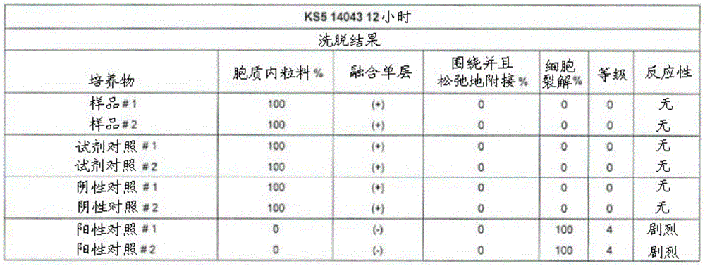

Claims (10)
1. A method for stimulating the lacrimal gland, comprising:
placing an arm of a nasal stimulator device against nasal or sinus tissue, the arm having a distal end and a conductive hydrogel disposed at the distal end; and is
Activating the nasal stimulator device to provide electrical stimulation to the nasal or sinus tissue,
wherein the electrically conductive hydrogel is for facilitating an electrical connection between a nasal stimulator device and nasal or sinus tissue, and the electrically conductive hydrogel comprises a mixture of:
glycerol monomethacrylate;
trimethylolpropane trimethacrylate;
dimethylacrylamide;
n-vinyl pyrrolidone;
2,4, 6-trimethylbenzoyl-diphenylphosphine oxide; and
methanol.
2. The method of claim 1, wherein the electrically conductive hydrogel further comprises a hydration medium.
3. The method of claim 2, wherein the hydration medium comprises propylene glycol.
4. The method of claim 3, wherein the hydration medium comprises from 5% to 85% by volume propylene glycol.
5. The method of claim 3, wherein the hydration medium comprises 35% propylene glycol by volume.
6. The method of claim 3, wherein the hydration medium comprises 40% propylene glycol by volume.
7. The method of claim 3, wherein the hydration medium comprises 45% propylene glycol by volume.
8. The method of claim 3, wherein the hydration medium comprises 50% by volume propylene glycol.
9. The method of any one of claims 1-8, wherein the electrically conductive hydrogel further comprises 3- (trimethyloxysilyl) propyl methacrylate.
10. A nasal stimulator device, comprising:
a reusable housing;
a disposable component removably attached to the reusable shell and comprising an arm having a distal end extending therefrom when attached to the reusable shell;
an electrode disposed in the arm; and
an electrically conductive hydrogel as in any one of claims 1-9 at a distal end of the arm.
Applications Claiming Priority (9)
| Application Number | Priority Date | Filing Date | Title |
|---|---|---|---|
| US201461944340P | 2014-02-25 | 2014-02-25 | |
| US61/944,340 | 2014-02-25 | ||
| US201462027139P | 2014-07-21 | 2014-07-21 | |
| US62/027,139 | 2014-07-21 | ||
| US201462035221P | 2014-08-08 | 2014-08-08 | |
| US62/035,221 | 2014-08-08 | ||
| US201462067350P | 2014-10-22 | 2014-10-22 | |
| US62/067,350 | 2014-10-22 | ||
| CN201580021324.6A CN106470673B (en) | 2014-02-25 | 2015-02-24 | Polymer formulations for nasolacrimal irritation |
Related Parent Applications (1)
| Application Number | Title | Priority Date | Filing Date |
|---|---|---|---|
| CN201580021324.6A Division CN106470673B (en) | 2014-02-25 | 2015-02-24 | Polymer formulations for nasolacrimal irritation |
Publications (1)
| Publication Number | Publication Date |
|---|---|
| CN111298285A true CN111298285A (en) | 2020-06-19 |
Family
ID=53881227
Family Applications (2)
| Application Number | Title | Priority Date | Filing Date |
|---|---|---|---|
| CN202010020774.6A Pending CN111298285A (en) | 2014-02-25 | 2015-02-24 | Polymer formulations for nasolacrimal stimulation |
| CN201580021324.6A Expired - Fee Related CN106470673B (en) | 2014-02-25 | 2015-02-24 | Polymer formulations for nasolacrimal irritation |
Family Applications After (1)
| Application Number | Title | Priority Date | Filing Date |
|---|---|---|---|
| CN201580021324.6A Expired - Fee Related CN106470673B (en) | 2014-02-25 | 2015-02-24 | Polymer formulations for nasolacrimal irritation |
Country Status (12)
| Country | Link |
|---|---|
| US (4) | US9770583B2 (en) |
| EP (2) | EP3689338A1 (en) |
| JP (2) | JP6604963B2 (en) |
| CN (2) | CN111298285A (en) |
| AU (1) | AU2015223184B2 (en) |
| CA (1) | CA2940533A1 (en) |
| ES (1) | ES2812752T3 (en) |
| MX (2) | MX2016011118A (en) |
| RU (1) | RU2698711C2 (en) |
| SA (1) | SA516371733B1 (en) |
| WO (1) | WO2015130707A2 (en) |
| ZA (1) | ZA201605563B (en) |
Families Citing this family (41)
| Publication number | Priority date | Publication date | Assignee | Title |
|---|---|---|---|---|
| US9821159B2 (en) | 2010-11-16 | 2017-11-21 | The Board Of Trustees Of The Leland Stanford Junior University | Stimulation devices and methods |
| US20140228875A1 (en) | 2013-02-08 | 2014-08-14 | Nidus Medical, Llc | Surgical device with integrated visualization and cauterization |
| US9717627B2 (en) | 2013-03-12 | 2017-08-01 | Oculeve, Inc. | Implant delivery devices, systems, and methods |
| WO2014172693A2 (en) | 2013-04-19 | 2014-10-23 | Oculeve, Inc. | Nasal stimulation devices and methods |
| US20150031946A1 (en) | 2013-07-24 | 2015-01-29 | Nidus Medical, Llc | Direct vision cryosurgical probe and methods of use |
| US9687288B2 (en) | 2013-09-30 | 2017-06-27 | Arrinex, Inc. | Apparatus and methods for treating rhinitis |
| CN111298285A (en) | 2014-02-25 | 2020-06-19 | 奥库利维公司 | Polymer formulations for nasolacrimal stimulation |
| US9763743B2 (en) | 2014-07-25 | 2017-09-19 | Arrinex, Inc. | Apparatus and method for treating rhinitis |
| CA2956176A1 (en) | 2014-07-25 | 2016-01-28 | Oculeve, Inc. | Stimulation patterns for treating dry eye |
| MX2017005204A (en) | 2014-10-22 | 2017-12-14 | Oculeve Inc | Stimulation devices and methods for treating dry eye. |
| WO2016065213A1 (en) | 2014-10-22 | 2016-04-28 | Oculeve, Inc. | Implantable nasal stimulator systems and methods |
| WO2016065211A1 (en) | 2014-10-22 | 2016-04-28 | Oculeve, Inc. | Contact lens for increasing tear production |
| US10743838B2 (en) | 2015-02-25 | 2020-08-18 | Decision Sciences Medical Company, LLC | Acoustic signal transmission couplants and coupling mediums |
| US10004634B2 (en) | 2015-06-16 | 2018-06-26 | The Regents Of The University Of Colorado | Nasolacrimal implants and related methods for tear stimulation |
| US10759138B2 (en) | 2015-10-06 | 2020-09-01 | University Of Pittsburgh - Of The Commonwealth System Of Higher Education | Moisture permeable hydrogel composite materials |
| US10426958B2 (en) | 2015-12-04 | 2019-10-01 | Oculeve, Inc. | Intranasal stimulation for enhanced release of ocular mucins and other tear proteins |
| EP3413822B1 (en) | 2016-02-11 | 2023-08-30 | Arrinex, Inc. | Device for image guided post-nasal nerve ablation |
| US10252048B2 (en) | 2016-02-19 | 2019-04-09 | Oculeve, Inc. | Nasal stimulation for rhinitis, nasal congestion, and ocular allergies |
| WO2017192572A1 (en) * | 2016-05-02 | 2017-11-09 | Oculeve, Inc. | Intranasal stimulation for treatment of meibomian gland disease and blepharitis |
| EP3471638B1 (en) | 2016-06-15 | 2025-01-29 | Arrinex, Inc. | Devices for treating a lateral surface of a nasal cavity |
| US12233017B2 (en) | 2016-10-14 | 2025-02-25 | Olympic Ophthalmics, Inc. | Quiet handheld devices and methods for treatment of disorders |
| US11253312B2 (en) | 2016-10-17 | 2022-02-22 | Arrinex, Inc. | Integrated nasal nerve detector ablation-apparatus, nasal nerve locator, and methods of use |
| CA3045018A1 (en) | 2016-12-02 | 2018-06-07 | Oculeve, Inc. | Apparatus and method for dry eye forecast and treatment recommendation |
| AU2017376132A1 (en) | 2016-12-12 | 2019-07-11 | Neuronoff, Inc. | Electrode curable and moldable to contours of a target in bodily tissue and methods of manufacturing and placement and dispensers therefor |
| AU2018256964B2 (en) | 2017-04-28 | 2023-11-30 | Arrinex, Inc. | Systems and methods for locating blood vessels in the treatment of rhinitis |
| CA3067212A1 (en) | 2017-06-16 | 2018-12-20 | AesculaTech, Inc. | Thermoresponsive polymers and uses thereof |
| US11147735B2 (en) | 2018-02-26 | 2021-10-19 | Olympic Ophthalmics, Inc. | Therapeutic handheld devices for disorders |
| JP7252204B2 (en) * | 2018-03-23 | 2023-04-04 | 株式会社 資生堂 | Cosmetic raw materials and oil-in-water emulsified cosmetics using core-corona type polymer particles |
| CA3100086A1 (en) * | 2018-05-16 | 2019-11-21 | Gl Chemtec Vision Inc. | Hydrogel polymers |
| CN109456444B (en) * | 2018-10-22 | 2021-03-16 | 西南交通大学 | A kind of preparation method of adhesive conductive hydrogel for tissue repair |
| US20200155830A1 (en) * | 2018-11-16 | 2020-05-21 | ALLERGAN / Oculeve | Nasal neurostimulation device with electrically conductive plastic electrode |
| US12017389B2 (en) | 2019-03-06 | 2024-06-25 | Decision Sciences Medical Company, LLC | Methods for manufacturing and distributing semi-rigid acoustic coupling articles and packaging for ultrasound imaging |
| WO2020219705A1 (en) * | 2019-04-23 | 2020-10-29 | Allan Wegner | Semi-rigid acoustic coupling articles for ultrasound diagnostic and treatment applications |
| CN112023114A (en) * | 2019-06-03 | 2020-12-04 | 上海禾思凯尔医疗科技有限公司 | Lacrimal canaliculus obstruction core material for lacrimal canaliculus embolism operation and preparation method thereof |
| US11065461B2 (en) | 2019-07-08 | 2021-07-20 | Bioness Inc. | Implantable power adapter |
| US11807700B2 (en) | 2020-08-17 | 2023-11-07 | Saudi Arabian Oil Company | Electro-responsive hydrogel for reservoir and downhole application |
| US12253467B2 (en) | 2021-12-13 | 2025-03-18 | Saudi Arabian Oil Company | Determining partition coefficients of tracer analytes |
| US12000278B2 (en) | 2021-12-16 | 2024-06-04 | Saudi Arabian Oil Company | Determining oil and water production rates in multiple production zones from a single production well |
| WO2024020160A1 (en) * | 2022-07-20 | 2024-01-25 | Texas Heart Institute | Tool and method for cardiac ablation using hydrogel |
| US12276180B2 (en) | 2023-05-17 | 2025-04-15 | Saudi Arabian Oil Company | Hydrogels for carbon sequestration and sealing zones in a wellbore |
| WO2024249599A2 (en) * | 2023-06-02 | 2024-12-05 | Kayser Laure V | Photo-catalyzed formation of conductive hydrogels |
Citations (5)
| Publication number | Priority date | Publication date | Assignee | Title |
|---|---|---|---|---|
| US6036891A (en) * | 1998-05-11 | 2000-03-14 | Pharmacia & Upjohn | Polymerizable hydrophilic ultraviolet light absorbing monomers |
| US20050113510A1 (en) * | 2001-05-01 | 2005-05-26 | Feldstein Mikhail M. | Method of preparing polymeric adhesive compositions utilizing the mechanism of interaction between the polymer components |
| US20050137276A1 (en) * | 2003-12-18 | 2005-06-23 | Kimberly-Clark Worldwide, Inc. | Electrically conductive adhesive hydrogels with solubilizer |
| US20050240147A1 (en) * | 2004-04-21 | 2005-10-27 | Exploramed Ii, Inc. | Devices, systems and methods for diagnosing and treating sinusitus and other disorders of the ears, nose and/or throat |
| US20100114273A1 (en) * | 2008-10-30 | 2010-05-06 | Philip Edward Muccio | Electrode for functional electrical stimulation |
Family Cites Families (425)
| Publication number | Priority date | Publication date | Assignee | Title |
|---|---|---|---|---|
| US2525381A (en) | 1947-09-25 | 1950-10-10 | Tower Paul | Contact-type electrode holder |
| US2512882A (en) | 1949-08-17 | 1950-06-27 | R G Truesdale Co Inc | Serum inoculator |
| US3620219A (en) | 1969-05-07 | 1971-11-16 | Donald E Barker | Facial nerve stimulator |
| US3709228A (en) | 1971-01-07 | 1973-01-09 | D Barker | Apparatus for facial stimulation |
| FR2210298A5 (en) | 1972-12-08 | 1974-07-05 | Commissariat Energie Atomique | |
| USD257495S (en) | 1979-05-29 | 1980-11-04 | Hot Shot Products Co. | Housing for an electric cattle prod |
| US4684362A (en) | 1981-03-12 | 1987-08-04 | Holt James J | Method for collecting nasal secretions |
| US4520825A (en) | 1982-04-30 | 1985-06-04 | Medtronic, Inc. | Digital circuit for control of gradual turn-on of electrical tissue stimulators |
| US4495676A (en) | 1982-08-02 | 1985-01-29 | Hartmetz Ii Gerald J | Apparatus for electrically stimulating an animal carcass |
| CH677883A5 (en) | 1982-11-15 | 1991-07-15 | Symtonic Sa | |
| US4539988A (en) | 1983-07-05 | 1985-09-10 | Packaging Corporation International | Disposable automatic lancet |
| US5025807A (en) | 1983-09-14 | 1991-06-25 | Jacob Zabara | Neurocybernetic prosthesis |
| US4590942A (en) | 1984-02-17 | 1986-05-27 | Biosonics, Inc. | Apparatus and method for inhibiting nasal secretions |
| DE3501095A1 (en) | 1985-01-15 | 1986-07-17 | Gerd Prof. Dr. 8520 Erlangen Kobal | METHOD FOR MEASURING SENSORY QUALITIES AND DEVICE FOR IMPLEMENTING THE METHOD |
| JPS61203935A (en) | 1985-03-07 | 1986-09-09 | 日石三菱株式会社 | Electrode for measuring electroretinogram |
| US4628933A (en) | 1985-07-23 | 1986-12-16 | Michelson Robin P | Method and apparatus for visual prosthesis |
| NZ214348A (en) | 1985-11-27 | 1988-07-28 | Walker T H & Sons Ltd | Electrically stunning animals through nose and neck contacts |
| US4868154A (en) | 1986-02-19 | 1989-09-19 | Eye Research Institute Of Retina Foundation | Stimulation of tear secretion with melanocyte stimulating hormones |
| US4777954A (en) | 1986-06-30 | 1988-10-18 | Nepera Inc. | Conductive adhesive medical electrode assemblies |
| US4706680A (en) | 1986-06-30 | 1987-11-17 | Nepera Inc. | Conductive adhesive medical electrode assemblies |
| US4957480A (en) | 1988-02-02 | 1990-09-18 | Universal Health Products, Inc. | Method of facial toning |
| US4926880A (en) | 1988-11-08 | 1990-05-22 | Microcurrents | Method for relieving sinus and nasal congestion utilizing microcurrents |
| US4988358A (en) | 1988-12-28 | 1991-01-29 | Eppley Barry L | Method for promoting hard tissue growth and repair in mammals |
| US5259373A (en) | 1989-05-19 | 1993-11-09 | Puritan-Bennett Corporation | Inspiratory airway pressure system controlled by the detection and analysis of patient airway sounds |
| RU1799577C (en) | 1989-08-17 | 1993-03-07 | Межотраслевой научно-технический комплекс "Микрохирургия глаза" | Method for improving vision function affected by ophthalmic nerve and retina disease |
| US5078733A (en) | 1990-04-12 | 1992-01-07 | Eveleigh Robert B | Pacifier for premature newborns |
| US5090422A (en) | 1990-04-19 | 1992-02-25 | Cardiac Pacemakers, Inc. | Implantable electrode pouch |
| US5099829A (en) | 1990-04-25 | 1992-03-31 | Wu An Chuan | Massage device good for eyes |
| US5342410A (en) | 1990-10-05 | 1994-08-30 | Eric Braverman | Apparatus and method for increasing the amplitude of P300 waves in the human brain |
| US5072724A (en) | 1990-11-23 | 1991-12-17 | Joseph Marcus | Vibrational liquid-wave stimulating therapy mask apparatus for facial health and beauty care |
| US5533470A (en) | 1991-07-05 | 1996-07-09 | Rose; Andrew F. | Electronic nose-clip with solar cell |
| US5640978A (en) | 1991-11-06 | 1997-06-24 | Diolase Corporation | Method for pain relief using low power laser light |
| US5193539A (en) | 1991-12-18 | 1993-03-16 | Alfred E. Mann Foundation For Scientific Research | Implantable microstimulator |
| US6063079A (en) | 1995-06-07 | 2000-05-16 | Arthrocare Corporation | Methods for electrosurgical treatment of turbinates |
| US5352445A (en) | 1992-05-07 | 1994-10-04 | Lavaux Joseph E | Lavaux tear test lacrimal equilibration time (LET) |
| US5514131A (en) | 1992-08-12 | 1996-05-07 | Stuart D. Edwards | Method for the ablation treatment of the uvula |
| US5360438A (en) | 1993-01-26 | 1994-11-01 | Fisher Mary R | Method and device for improving cranial nerve function to improve muscle function and thereby overcome visual/perceptual dysfunction |
| WO1994017110A1 (en) * | 1993-01-28 | 1994-08-04 | Pilkington Barnes Hind, Inc. | Material in the manufacture of polymeric articles |
| US5345948A (en) | 1993-04-08 | 1994-09-13 | Donnell Jr Francis E O | Method of performing translactrimal laser dacryocystorhinostomy |
| US5545617A (en) | 1993-11-12 | 1996-08-13 | The Schepens Eye Research Institute, Inc. | Therapeutic regulation of abnormal conjunctival goblet cell mucous secretion |
| US5713833A (en) | 1994-01-26 | 1998-02-03 | Milligan; Lee John | Septum nerve stimulator |
| CN1050567C (en) | 1994-01-31 | 2000-03-22 | 博士伦公司 | Method of cast molding toric contact lenses |
| IL108772A0 (en) | 1994-02-24 | 1994-05-30 | Amcor Ltd | Treatment of rhinitis by biostimulative illumination |
| AUPM982694A0 (en) | 1994-12-02 | 1995-01-05 | University Of Queensland, The | Iontophoresis method and apparatus |
| US5643336A (en) | 1995-01-09 | 1997-07-01 | Lopez-Claros; Marcelo Enrique | Heating and cooling pad |
| US5735817A (en) | 1995-05-19 | 1998-04-07 | Shantha; T. R. | Apparatus for transsphenoidal stimulation of the pituitary gland and adjoining brain structures |
| US5640764A (en) | 1995-05-22 | 1997-06-24 | Alfred E. Mann Foundation For Scientific Research | Method of forming a tubular feed-through hermetic seal for an implantable medical device |
| US5571101A (en) | 1995-05-25 | 1996-11-05 | Ellman; Alan G. | Electrosurgical electrode for DCR surgical procedure |
| US5707400A (en) | 1995-09-19 | 1998-01-13 | Cyberonics, Inc. | Treating refractory hypertension by nerve stimulation |
| US5607461A (en) | 1995-10-20 | 1997-03-04 | Nexmed, Inc. | Apparatus and method for delivering electrical stimulus to tissue |
| DE19549297C2 (en) | 1995-12-22 | 1998-07-02 | Guenter Stielau | Method and device for influencing the human psyche |
| US6051017A (en) | 1996-02-20 | 2000-04-18 | Advanced Bionics Corporation | Implantable microstimulator and systems employing the same |
| US5900407A (en) | 1997-02-06 | 1999-05-04 | Inspire Pharmaceuticals, Inc. | Method of treating dry eye disease with uridine triphosphates and related compounds |
| DE69733261T2 (en) | 1996-08-23 | 2006-01-19 | Osteobiologics, Inc., San Antonio | PORTABLE MATERIAL TEST UNIT |
| US5697957A (en) | 1996-08-29 | 1997-12-16 | Pacesetter Ab | Adaptive method and apparatus for extracting an evoked response component from a sensed cardiac signal by suppressing electrode polarization components |
| US6544193B2 (en) | 1996-09-04 | 2003-04-08 | Marcio Marc Abreu | Noninvasive measurement of chemical substances |
| US5800685A (en) * | 1996-10-28 | 1998-09-01 | Cardiotronics Systems, Inc. | Electrically conductive adhesive hydrogels |
| US7460911B2 (en) | 1997-02-26 | 2008-12-02 | Alfred E. Mann Foundation For Scientific Research | System and method suitable for treatment of a patient with a neurological deficit by sequentially stimulating neural pathways using a system of discrete implantable medical devices |
| US7799337B2 (en) | 1997-07-21 | 2010-09-21 | Levin Bruce H | Method for directed intranasal administration of a composition |
| US6458157B1 (en) | 1997-08-04 | 2002-10-01 | Suaning Gregg Joergen | Retinal stimulator |
| US6020445A (en) * | 1997-10-09 | 2000-02-01 | Johnson & Johnson Vision Products, Inc. | Silicone hydrogel polymers |
| AU1205799A (en) | 1997-10-29 | 1999-05-17 | J-Med Pharmaceuticals, Inc. | Antihistamine/decongestant regimens for treating rhinitis |
| US6083251A (en) | 1997-11-13 | 2000-07-04 | Shindo; Kohei | Eye treatment method and apparatus |
| FR2771297B1 (en) | 1997-11-25 | 2000-02-11 | Pierre Andre Jacques Bige | TWO-CHANNEL PROBE FOR TREATING EYEWEEDING |
| US6050999A (en) | 1997-12-18 | 2000-04-18 | Keravision, Inc. | Corneal implant introducer and method of use |
| US5935155A (en) | 1998-03-13 | 1999-08-10 | John Hopkins University, School Of Medicine | Visual prosthesis and method of using same |
| US6324429B1 (en) | 1998-05-08 | 2001-11-27 | Massachusetts Eye And Ear Infirmary | Chronically implantable retinal prosthesis |
| CA2336190A1 (en) | 1998-07-06 | 2000-01-13 | Advanced Bionics Corporation | Implantable stimulator system and method for treatment of urinary incontinence |
| US6035236A (en) | 1998-07-13 | 2000-03-07 | Bionergy Therapeutics, Inc. | Methods and apparatus for electrical microcurrent stimulation therapy |
| US6272382B1 (en) | 1998-07-31 | 2001-08-07 | Advanced Bionics Corporation | Fully implantable cochlear implant system |
| US6240316B1 (en) | 1998-08-14 | 2001-05-29 | Advanced Bionics Corporation | Implantable microstimulation system for treatment of sleep apnea |
| CA2341708A1 (en) | 1998-09-04 | 2000-03-16 | Wolfe Research Pty. Ltd. | Medical implant system |
| US7346389B1 (en) | 1998-09-24 | 2008-03-18 | Newsome David A | Dilation enhancer with pre-medicated contact lenses |
| US6275737B1 (en) | 1998-10-14 | 2001-08-14 | Advanced Bionics Corporation | Transcutaneous transmission pouch |
| US5948006A (en) | 1998-10-14 | 1999-09-07 | Advanced Bionics Corporation | Transcutaneous transmission patch |
| US7076307B2 (en) | 2002-05-09 | 2006-07-11 | Boveja Birinder R | Method and system for modulating the vagus nerve (10th cranial nerve) with electrical pulses using implanted and external components, to provide therapy neurological and neuropsychiatric disorders |
| US6366814B1 (en) | 1998-10-26 | 2002-04-02 | Birinder R. Boveja | External stimulator for adjunct (add-on) treatment for neurological, neuropsychiatric, and urological disorders |
| US6564102B1 (en) | 1998-10-26 | 2003-05-13 | Birinder R. Boveja | Apparatus and method for adjunct (add-on) treatment of coma and traumatic brain injury with neuromodulation using an external stimulator |
| US6208902B1 (en) | 1998-10-26 | 2001-03-27 | Birinder Bob Boveja | Apparatus and method for adjunct (add-on) therapy for pain syndromes utilizing an implantable lead and an external stimulator |
| US6205359B1 (en) | 1998-10-26 | 2001-03-20 | Birinder Bob Boveja | Apparatus and method for adjunct (add-on) therapy of partial complex epilepsy, generalized epilepsy and involuntary movement disorders utilizing an external stimulator |
| US6329485B1 (en) * | 1998-12-11 | 2001-12-11 | Bausch & Lomb Incorporated | High refractive index hydrogel compositions for ophthalmic implants |
| GB2345010B (en) | 1998-12-17 | 2002-12-31 | Electrosols Ltd | A delivery device |
| AU772100B2 (en) | 1999-02-08 | 2004-04-08 | Cochlear Limited | Offset coils for radio frequency transcutaneous links |
| US6438398B1 (en) | 1999-03-05 | 2002-08-20 | The University Of Miami | Process and device for measuring tear fluorescein clearance |
| WO2000056393A1 (en) | 1999-03-24 | 2000-09-28 | Second Sight, Llc | Retinal color prosthesis for color sight restoration |
| WO2000062672A1 (en) | 1999-04-15 | 2000-10-26 | Surgi-Vision | Methods for in vivo magnetic resonance imaging |
| US6178352B1 (en) | 1999-05-07 | 2001-01-23 | Woodside Biomedical, Inc. | Method of blood pressure moderation |
| US6200626B1 (en) * | 1999-05-20 | 2001-03-13 | Bausch & Lomb Incorporated | Surface-treatment of silicone medical devices comprising an intermediate carbon coating and graft polymerization |
| US6516227B1 (en) | 1999-07-27 | 2003-02-04 | Advanced Bionics Corporation | Rechargeable spinal cord stimulator system |
| US7177690B2 (en) | 1999-07-27 | 2007-02-13 | Advanced Bionics Corporation | Implantable system having rechargeable battery indicator |
| US6237604B1 (en) | 1999-09-07 | 2001-05-29 | Scimed Life Systems, Inc. | Systems and methods for preventing automatic identification of re-used single use devices |
| US6368324B1 (en) | 1999-09-24 | 2002-04-09 | Medtronic Xomed, Inc. | Powered surgical handpiece assemblies and handpiece adapter assemblies |
| US6853946B2 (en) | 1999-11-05 | 2005-02-08 | Adam Cohen | Air flow sensing and control for animal confinement system |
| EP1110509A1 (en) | 1999-12-21 | 2001-06-27 | Tomaso Vercellotti | Surgical device for bone surgery |
| US6885888B2 (en) | 2000-01-20 | 2005-04-26 | The Cleveland Clinic Foundation | Electrical stimulation of the sympathetic nerve chain |
| US20040039401A1 (en) | 2000-03-31 | 2004-02-26 | Chow Alan Y. | Implant instrument |
| US6277855B1 (en) | 2000-04-21 | 2001-08-21 | Inspire Pharmaceuticals, Inc. | Method of treating dry eye disease with nicotinic acetylcholine receptor agonists |
| US6284765B1 (en) | 2000-04-27 | 2001-09-04 | The University Of North Texas Health Science Center At Fort Worth | (+) naloxone and epinephrine combination therapy |
| US6853858B2 (en) | 2000-05-08 | 2005-02-08 | Brainsgate, Ltd. | Administration of anti-inflammatory drugs into the central nervous system |
| US7117033B2 (en) | 2000-05-08 | 2006-10-03 | Brainsgate, Ltd. | Stimulation for acute conditions |
| US7146209B2 (en) | 2000-05-08 | 2006-12-05 | Brainsgate, Ltd. | Stimulation for treating eye pathologies |
| CA2408097A1 (en) | 2000-05-08 | 2001-11-15 | Brainsgate Ltd. | Method and apparatus for stimulating the sphenopalatine ganglion to modify properties of the bbb and cerebral blood flow |
| US20020035358A1 (en) | 2000-05-09 | 2002-03-21 | Ming Wang | Pulsed electromagnetic field therapy for treatment of corneal disorders and injuries |
| US6327504B1 (en) | 2000-05-10 | 2001-12-04 | Thoratec Corporation | Transcutaneous energy transfer with circuitry arranged to avoid overheating |
| US6592860B1 (en) * | 2000-05-30 | 2003-07-15 | Soluble Systems, Llc | Composition and applicator for topical substance delivery |
| US6526318B1 (en) | 2000-06-16 | 2003-02-25 | Mehdi M. Ansarinia | Stimulation method for the sphenopalatine ganglia, sphenopalatine nerve, or vidian nerve for treatment of medical conditions |
| US6505077B1 (en) | 2000-06-19 | 2003-01-07 | Medtronic, Inc. | Implantable medical device with external recharging coil electrical connection |
| EP1166820B1 (en) | 2000-06-19 | 2009-09-30 | Medtronic, Inc. | Implantable medical device with external recharging coil |
| US6871099B1 (en) | 2000-08-18 | 2005-03-22 | Advanced Bionics Corporation | Fully implantable microstimulator for spinal cord stimulation as a therapy for chronic pain |
| US6539253B2 (en) | 2000-08-26 | 2003-03-25 | Medtronic, Inc. | Implantable medical device incorporating integrated circuit notch filters |
| US6535766B1 (en) | 2000-08-26 | 2003-03-18 | Medtronic, Inc. | Implanted medical device telemetry using integrated microelectromechanical filtering |
| DE60143621D1 (en) | 2000-09-13 | 2011-01-20 | DEVICE FOR CONDITIONING MUSCLES IN SLEEP | |
| US6895279B2 (en) | 2000-09-15 | 2005-05-17 | Alfred E. Mann Institute For Biomedical Engineering At The University Of Southern California | Method and apparatus to treat disorders of gastrointestinal peristalsis |
| US6405079B1 (en) | 2000-09-22 | 2002-06-11 | Mehdi M. Ansarinia | Stimulation method for the dural venous sinuses and adjacent dura for treatment of medical conditions |
| US6652095B2 (en) | 2000-11-17 | 2003-11-25 | Hsiao-Ching Tung | Orthokeratology and bi-focal contact lens |
| US20050251061A1 (en) | 2000-11-20 | 2005-11-10 | Schuler Eleanor L | Method and system to record, store and transmit waveform signals to regulate body organ function |
| JP2002159340A (en) | 2000-11-28 | 2002-06-04 | Ya Man Ltd | Cosmetological device |
| WO2002060522A2 (en) | 2001-01-30 | 2002-08-08 | Saliwizer Itd. | System and method for electrical stimulation of salivation |
| EP1234553A1 (en) | 2001-02-14 | 2002-08-28 | Boris-Wolfgang Hochleitner | Bioartificial device |
| JP4781576B2 (en) | 2001-02-28 | 2011-09-28 | 株式会社ニデック | Implantable visual stimulator |
| NO313683B1 (en) | 2001-03-21 | 2002-11-18 | Turid Bergersen | Device for acupressuric treatment |
| US6701189B2 (en) | 2001-03-30 | 2004-03-02 | Neurocontrol Corporation | Systems and methods for performing prosthetic or therapeutic neuromuscular stimulation using a universal external controller accommodating different control inputs and/or different control outputs |
| WO2002078592A2 (en) | 2001-03-30 | 2002-10-10 | Case Western Reserve University | Systems and methods for selectively stimulating components in, on, or near the pudendal nerve or its branches to achieve selective physiologic responses |
| US6662052B1 (en) | 2001-04-19 | 2003-12-09 | Nac Technologies Inc. | Method and system for neuromodulation therapy using external stimulator with wireless communication capabilites |
| US7369897B2 (en) | 2001-04-19 | 2008-05-06 | Neuro And Cardiac Technologies, Llc | Method and system of remotely controlling electrical pulses provided to nerve tissue(s) by an implanted stimulator system for neuromodulation therapies |
| WO2002086105A1 (en) | 2001-04-20 | 2002-10-31 | Chiron Corporation | Delivery of polynucleotide agents to the central nervous sysstem |
| US6907295B2 (en) | 2001-08-31 | 2005-06-14 | Biocontrol Medical Ltd. | Electrode assembly for nerve control |
| AT411150B (en) | 2001-05-25 | 2003-10-27 | Nova Technical Res Gmbh | DEVICE FOR INTRODUCING SUBSTANCES |
| US6537265B2 (en) | 2001-06-08 | 2003-03-25 | Health Research, Inc. | Method for nasal application of a medicinal substance |
| US6792314B2 (en) | 2001-06-18 | 2004-09-14 | Alfred E. Mann Foundation For Scientific Research | Miniature implantable array and stimulation system suitable for eyelid stimulation |
| US7054692B1 (en) | 2001-06-22 | 2006-05-30 | Advanced Bionics Corporation | Fixation device for implantable microdevices |
| US20050004625A1 (en) | 2001-06-29 | 2005-01-06 | Chow Alan Y. | Treatment of degenerative retinal disease via electrical stimulation of surface structures |
| US7031776B2 (en) | 2001-06-29 | 2006-04-18 | Optobionics | Methods for improving damaged retinal cell function |
| US7331984B2 (en) | 2001-08-28 | 2008-02-19 | Glaukos Corporation | Glaucoma stent for treating glaucoma and methods of use |
| US7974693B2 (en) | 2001-08-31 | 2011-07-05 | Bio Control Medical (B.C.M.) Ltd. | Techniques for applying, configuring, and coordinating nerve fiber stimulation |
| US7885709B2 (en) | 2001-08-31 | 2011-02-08 | Bio Control Medical (B.C.M.) Ltd. | Nerve stimulation for treating disorders |
| US7778703B2 (en) | 2001-08-31 | 2010-08-17 | Bio Control Medical (B.C.M.) Ltd. | Selective nerve fiber stimulation for treating heart conditions |
| US7778711B2 (en) | 2001-08-31 | 2010-08-17 | Bio Control Medical (B.C.M.) Ltd. | Reduction of heart rate variability by parasympathetic stimulation |
| US6792312B2 (en) | 2001-09-06 | 2004-09-14 | Medtronic, Inc. | Connector module having internal weld plates |
| US20030062050A1 (en) | 2001-10-01 | 2003-04-03 | Bruno Schmidt | Anti-snoring devices and methods |
| US6829508B2 (en) | 2001-10-19 | 2004-12-07 | Alfred E. Mann Foundation For Scientific Research | Electrically sensing and stimulating system for placement of a nerve stimulator or sensor |
| US6562036B1 (en) | 2001-12-10 | 2003-05-13 | Ellman Alan G | Electrosurgical electrode for rhinoplasty |
| JP2003210513A (en) | 2002-01-23 | 2003-07-29 | Nidek Co Ltd | Ophthalmic treatment equipment |
| JP3838933B2 (en) * | 2002-03-19 | 2006-10-25 | 積水化成品工業株式会社 | Polymer hydrogel electrode |
| JP4295627B2 (en) | 2002-03-27 | 2009-07-15 | シーブイアールエックス, インコーポレイテッド | Electrode structure and its use in controlling circulatory system reflection |
| US6641799B2 (en) | 2002-04-03 | 2003-11-04 | Nos Spray, Inc. | Nasal spray for decongesting nasal passages |
| US7142909B2 (en) | 2002-04-11 | 2006-11-28 | Second Sight Medical Products, Inc. | Biocompatible bonding method and electronics package suitable for implantation |
| US6974533B2 (en) | 2002-04-11 | 2005-12-13 | Second Sight Medical Products, Inc. | Platinum electrode and method for manufacturing the same |
| US7645262B2 (en) | 2002-04-11 | 2010-01-12 | Second Sight Medical Products, Inc. | Biocompatible bonding method and electronics package suitable for implantation |
| US6604528B1 (en) | 2002-04-22 | 2003-08-12 | Lloyd P. Duncan | Acid reflux and snoring device |
| WO2004043218A2 (en) | 2002-11-14 | 2004-05-27 | Brainsgate Ltd. | Surgical tools and techniques for stimulation |
| US20060004423A1 (en) | 2002-05-09 | 2006-01-05 | Boveja Birinder R | Methods and systems to provide therapy or alleviate symptoms of chronic headache, transformed migraine, and occipital neuralgia by providing rectangular and/or complex electrical pulses to occipital nerves |
| US8204591B2 (en) | 2002-05-23 | 2012-06-19 | Bio Control Medical (B.C.M.) Ltd. | Techniques for prevention of atrial fibrillation |
| US8036745B2 (en) | 2004-06-10 | 2011-10-11 | Bio Control Medical (B.C.M.) Ltd. | Parasympathetic pacing therapy during and following a medical procedure, clinical trauma or pathology |
| JP2005528169A (en) | 2002-06-03 | 2005-09-22 | メド−エル・エレクトロメディツィニシェ・ゲラーテ・ゲーエムベーハー | Implantable device with flexible interconnect to coil |
| US7069084B2 (en) | 2002-06-14 | 2006-06-27 | Seefit Incorporated | Method and apparatus for preventing and treating eyelid problems |
| US7860570B2 (en) | 2002-06-20 | 2010-12-28 | Boston Scientific Neuromodulation Corporation | Implantable microstimulators and methods for unidirectional propagation of action potentials |
| US20040147973A1 (en) | 2002-06-27 | 2004-07-29 | Hauser Robert G. | Intra cardiac pacer and method |
| US6904868B2 (en) | 2002-07-12 | 2005-06-14 | Robert S. Block | Interactive mobile food dispenser |
| BRPI0314288B8 (en) | 2002-09-18 | 2021-06-22 | Allergan Inc | devices for sending eye implants |
| US7169163B2 (en) | 2002-09-30 | 2007-01-30 | Bruce Becker | Transnasal method and catheter for lacrimal system |
| AU2003284018A1 (en) | 2002-10-04 | 2004-05-04 | Microchips, Inc. | Medical device for neural stimulation and controlled drug delivery |
| US7349741B2 (en) | 2002-10-11 | 2008-03-25 | Advanced Bionics, Llc | Cochlear implant sound processor with permanently integrated replenishable power source |
| US7024241B1 (en) | 2002-12-05 | 2006-04-04 | Pacesetter, Inc. | Pacing pulse waveforms that support simultaneous intracardiac signal sensing and analysis |
| TR200202651A2 (en) | 2002-12-12 | 2004-07-21 | Met�N�Tulgar | the vücutádışındanádirekátedaviásinyaliátransferliáábeyinápil |
| US7264859B2 (en) * | 2002-12-19 | 2007-09-04 | Kimberly-Clark Worldwide, Inc. | Lubricious coating for medical devices |
| US20050048099A1 (en) | 2003-01-09 | 2005-03-03 | Allergan, Inc. | Ocular implant made by a double extrusion process |
| US7228184B2 (en) | 2003-02-22 | 2007-06-05 | Chester Heath | Viral-inhibiting method |
| US7321795B2 (en) | 2003-03-24 | 2008-01-22 | Les Bogdanowicz | Compositions for electric stimulation of the eye |
| WO2004091453A1 (en) | 2003-04-15 | 2004-10-28 | Eyeborn (Proprietary) Limited | An orbital implant applicator |
| US20060074450A1 (en) | 2003-05-11 | 2006-04-06 | Boveja Birinder R | System for providing electrical pulses to nerve and/or muscle using an implanted stimulator |
| US7317947B2 (en) | 2003-05-16 | 2008-01-08 | Medtronic, Inc. | Headset recharger for cranially implantable medical devices |
| US7725176B2 (en) | 2003-07-10 | 2010-05-25 | Schuler Eleanor L | Method and system for regulation of endocrine and exocrine glands by means of neuro-electrical coded signals |
| MXPA06000239A (en) | 2003-07-10 | 2006-04-07 | Science Medicus Inc | Regulation of endocrine and exocrine glands by means of neuro-electrical coded signals. |
| JP2005052461A (en) | 2003-08-06 | 2005-03-03 | Pop Denshi Kk | Electric current applying device for organism |
| CN1253147C (en) * | 2003-08-13 | 2006-04-26 | 复旦大学 | Ultra porous hydrogel complex substance, preparing method and use in pharmaceutics thereof |
| ES2243116B1 (en) | 2003-09-22 | 2007-02-01 | Josep Duran Von Arx | NASAL STIMULATOR. |
| US7225032B2 (en) | 2003-10-02 | 2007-05-29 | Medtronic Inc. | External power source, charger and system for an implantable medical device having thermal characteristics and method therefore |
| DE10353000A1 (en) | 2003-11-13 | 2005-06-16 | Physiomed Elektromedizin Ag | Device for electrotherapy |
| AU2003296968A1 (en) | 2003-12-12 | 2005-07-14 | Richard W. Yee | Method and apparatus for preventing and treating eyelid problems |
| WO2005070494A1 (en) | 2004-01-22 | 2005-08-04 | Rehabtronics Inc. | Method of routing electrical current to bodily tissues via implanted passive conductors |
| US8055347B2 (en) | 2005-08-19 | 2011-11-08 | Brainsgate Ltd. | Stimulation for treating brain events and other conditions |
| US20050203600A1 (en) | 2004-03-12 | 2005-09-15 | Scimed Life Systems, Inc. | Collapsible/expandable tubular electrode leads |
| US7993381B2 (en) | 2004-04-01 | 2011-08-09 | Mac Beam, Inc. | Method and apparatus for treating the body |
| US7571007B2 (en) | 2004-04-12 | 2009-08-04 | Advanced Neuromodulation Systems, Inc. | Systems and methods for use in pulse generation |
| US7359751B1 (en) | 2004-05-05 | 2008-04-15 | Advanced Neuromodulation Systems, Inc. | Clinician programmer for use with trial stimulator |
| US7402175B2 (en) | 2004-05-17 | 2008-07-22 | Massachusetts Eye & Ear Infirmary | Vision prosthesis orientation |
| US7330762B2 (en) | 2004-06-07 | 2008-02-12 | Neuro And Cardiac Technologies, Llc | Method and system for providing pulsed electrical stimulation to provide therapy for erectile/sexual dysfunction, prostatitis, prostatitis pain, and chronic pelvic pain |
| US20050268472A1 (en) | 2004-06-07 | 2005-12-08 | Bourilkov Jordan T | Shaving systems |
| US20060018872A1 (en) * | 2004-06-16 | 2006-01-26 | Tew Gregory N | Poly(lactic acid) copolymer hydrogels and related methods of drug delivery |
| WO2006021957A2 (en) | 2004-08-23 | 2006-03-02 | Brainsgate Ltd. | Concurrent bilateral spg modulation |
| US20090099623A1 (en) | 2004-09-13 | 2009-04-16 | Neuronix Ltd. | Systems and methods for treatment of medical conditions related to the central nervous system and for enhancing cognitive functions |
| US7641688B2 (en) | 2004-09-16 | 2010-01-05 | Evera Medical, Inc. | Tissue augmentation device |
| GB2418143B (en) | 2004-09-21 | 2010-03-17 | Can Do Corp Ltd | Apparatus for behaviour modification |
| US7247692B2 (en) * | 2004-09-30 | 2007-07-24 | Johnson & Johnson Vision Care, Inc. | Biomedical devices containing amphiphilic block copolymers |
| US7650186B2 (en) | 2004-10-20 | 2010-01-19 | Boston Scientific Scimed, Inc. | Leadless cardiac stimulation systems |
| EP1812104B1 (en) | 2004-10-20 | 2012-11-21 | Boston Scientific Limited | Leadless cardiac stimulation systems |
| US7497836B2 (en) | 2004-10-22 | 2009-03-03 | General Patent Llc | Germicidal method for treating or preventing sinusitis |
| CN100574700C (en) * | 2004-10-28 | 2009-12-30 | 桑特拉医学公司 | Systems and methods for analyte sampling and analysis using hydrogels |
| US8489189B2 (en) | 2004-10-29 | 2013-07-16 | Medtronic, Inc. | Expandable fixation mechanism |
| US20060095077A1 (en) | 2004-10-29 | 2006-05-04 | Tronnes Carole A | Expandable fixation structures |
| US20090264966A1 (en) | 2004-11-02 | 2009-10-22 | Pixeloptics, Inc. | Device for Inductive Charging of Implanted Electronic Devices |
| EP1652552B1 (en) | 2004-11-02 | 2008-09-17 | Sydney Biotech Pty. Ltd. | Extraocular device |
| US7547447B2 (en) | 2004-11-15 | 2009-06-16 | Doheny Eye Institute | Bioartificial lacrimal gland |
| US20060107958A1 (en) | 2004-11-22 | 2006-05-25 | Sleeper Geoffrey P | Adjustable sealing nasal cannula |
| EP1671670A1 (en) | 2004-12-14 | 2006-06-21 | STX Sprl | Apparatus for electrically inhibiting facial muscles |
| US20070250119A1 (en) | 2005-01-11 | 2007-10-25 | Wicab, Inc. | Systems and methods for altering brain and body functions and for treating conditions and diseases of the same |
| US8109981B2 (en) | 2005-01-25 | 2012-02-07 | Valam Corporation | Optical therapies and devices |
| US20120053648A1 (en) | 2005-02-08 | 2012-03-01 | Rolf Neher | Systems and methods for smoking cessation. |
| US20070248930A1 (en) | 2005-02-17 | 2007-10-25 | Biolux Research Ltd. | Light therapy apparatus and methods |
| US8224444B2 (en) | 2005-02-18 | 2012-07-17 | Bio Control Medical (B.C.M.) Ltd. | Intermittent electrical stimulation |
| JP4597702B2 (en) | 2005-02-24 | 2010-12-15 | ピジョン株式会社 | Lip closure |
| US20070060954A1 (en) | 2005-02-25 | 2007-03-15 | Tracy Cameron | Method of using spinal cord stimulation to treat neurological disorders or conditions |
| US7555345B2 (en) | 2005-03-11 | 2009-06-30 | Medtronic, Inc. | Implantable neurostimulator device |
| US7565204B2 (en) | 2005-03-24 | 2009-07-21 | Alfred E. Mann Foundation For Scientific Research | Implantable device for controlling received power by a power receiving unit therein |
| WO2006113305A2 (en) | 2005-04-13 | 2006-10-26 | The Cleveland Clinic Foundation | System and method for providing a waveform for stimulating biological tissue |
| EP1874356A2 (en) | 2005-04-15 | 2008-01-09 | Board of Trustees of Michigan State University | Aminergic pharmaceutical compositions and methods |
| US20060235430A1 (en) | 2005-04-15 | 2006-10-19 | Intralens Vision, Inc. | Corneal implant injector assembly and methods of use |
| JP2006311917A (en) | 2005-05-09 | 2006-11-16 | Shozo Terauchi | Low-frequency electric stimulation device |
| US7551958B2 (en) | 2005-05-24 | 2009-06-23 | Cardiac Pacemakers, Inc. | Safety control system for implantable neural stimulator |
| US7947076B2 (en) | 2005-06-03 | 2011-05-24 | Medtronic Xomed, Inc. | Nasal valve treatment method and apparatus |
| US20060276738A1 (en) | 2005-06-06 | 2006-12-07 | Becker Bruce B | Lacrimal drainage bypass device and method |
| EP1904154B1 (en) | 2005-06-09 | 2011-01-26 | Medtronic, Inc. | Implantable medical lead |
| WO2006135753A1 (en) | 2005-06-09 | 2006-12-21 | Medtronic, Inc. | Introducer for therapy delivery elements |
| US8606362B2 (en) | 2005-07-08 | 2013-12-10 | Boston Scientific Neuromodulation Corporation | Current output architecture for an implantable stimulator device |
| DE102005032989A1 (en) | 2005-07-14 | 2007-01-25 | Imi Intelligent Medical Implants Ag | Extraocular epiretinal implant |
| WO2013003594A2 (en) | 2011-06-28 | 2013-01-03 | Tearscience, Inc. | Methods and systems for treating meibomian gland dysfunction using radio-frequency energy |
| US7981095B2 (en) | 2005-07-18 | 2011-07-19 | Tearscience, Inc. | Methods for treating meibomian gland dysfunction employing fluid jet |
| US20070016256A1 (en) | 2005-07-18 | 2007-01-18 | Korb Donald R | Method and apparatus for treating gland dysfunction |
| US9962558B2 (en) | 2005-08-05 | 2018-05-08 | Gholam A. Peyman | Methods to regulate polarization and enhance function of cells |
| US20070031341A1 (en) | 2005-08-08 | 2007-02-08 | Dimauro Thomas M | Methods of delivering therapeutics to the brain |
| JP2007044323A (en) | 2005-08-11 | 2007-02-22 | Nidek Co Ltd | Eyesight regeneration supporting apparatus |
| US8005526B2 (en) | 2005-08-31 | 2011-08-23 | The Regents Of The University Of Michigan | Biologically integrated electrode devices |
| US7805202B2 (en) | 2005-09-30 | 2010-09-28 | Boston Scientific Neuromodulation Corporation | Implantable electrodes and insertion methods and tools |
| US8676324B2 (en) | 2005-11-10 | 2014-03-18 | ElectroCore, LLC | Electrical and magnetic stimulators used to treat migraine/sinus headache, rhinitis, sinusitis, rhinosinusitis, and comorbid disorders |
| US7729758B2 (en) | 2005-11-30 | 2010-06-01 | Boston Scientific Neuromodulation Corporation | Magnetically coupled microstimulators |
| US7444181B2 (en) | 2005-12-14 | 2008-10-28 | Boston Scientific Neuromodulation Corporation | Techniques for sensing and adjusting a compliance voltage in an implantable stimulator device |
| JP2009523503A (en) | 2006-01-16 | 2009-06-25 | コンティネンス コントロール システムズ インターナショナル プロプライエタリー リミテッド | Stimulator for controlling body functions |
| ES3042426T3 (en) | 2006-01-17 | 2025-11-20 | Alcon Inc | Glaucoma treatment device |
| CA2641821C (en) | 2006-02-16 | 2017-10-10 | Imthera Medical, Inc. | An rfid-based apparatus, system, and method for therapeutic treatment of a patient |
| US8118752B2 (en) | 2006-02-16 | 2012-02-21 | The Board Of Trustees Of The University Of Illinois | Apparatus and methods for mapping retinal function |
| IES20060134A2 (en) | 2006-02-23 | 2007-09-05 | Sensor Technologies And Device | Biomedical surface electrode |
| US20070219600A1 (en) | 2006-03-17 | 2007-09-20 | Michael Gertner | Devices and methods for targeted nasal phototherapy |
| US20070237797A1 (en) | 2006-03-28 | 2007-10-11 | Gholam A. Peyman | Neural Conduit Agent Dissemination |
| US20070250135A1 (en) | 2006-04-21 | 2007-10-25 | Bartz-Schmidt Karl U | Compound subretinal prostheses with extra-ocular parts and surgical technique therefore |
| US20070255333A1 (en) | 2006-04-28 | 2007-11-01 | Medtronic, Inc. | Neuromodulation therapy for perineal or dorsal branch of pudendal nerve |
| US9314369B2 (en) | 2006-05-15 | 2016-04-19 | Tearscience, Inc. | System for inner eyelid treatment of meibomian gland dysfunction |
| US20070276314A1 (en) | 2006-05-26 | 2007-11-29 | Becker Bruce B | Nasolacrimal duct probing, intubating and irrigating device |
| US20070299462A1 (en) | 2006-06-23 | 2007-12-27 | Becker Bruce B | Nasolacrimal system irrigation and dilatation tool |
| US20090204142A1 (en) | 2006-05-26 | 2009-08-13 | Becker Bruce B | Nasolacrimal system surgical tool and method |
| US8231218B2 (en) * | 2006-06-15 | 2012-07-31 | Coopervision International Holding Company, Lp | Wettable silicone hydrogel contact lenses and related compositions and methods |
| US8311634B2 (en) | 2006-06-16 | 2012-11-13 | Second Sight Medical Products Inc. | Apparatus and method for electrical stimulation of human retina |
| US20070299420A1 (en) | 2006-06-23 | 2007-12-27 | Minu, L.L.C. | Delivery of an agent using iontophoresis |
| US8080047B2 (en) | 2006-08-01 | 2011-12-20 | Mesure Technology Co., Ltd. | Light therapy device |
| US8295529B2 (en) | 2006-08-28 | 2012-10-23 | Bcinet, Inc. | Gaming headset with integrated microphone and adapted for olfactory stimulation |
| JP2008055000A (en) | 2006-08-31 | 2008-03-13 | Nidek Co Ltd | Visual regeneration device |
| ES2388003T3 (en) | 2006-09-20 | 2012-10-05 | Genzyme Corporation | A system based on FACS and the indicator protein for high-performance development of therapeutic proteins |
| EP2068710A4 (en) | 2006-09-27 | 2009-10-21 | Huntington Medical Res Inst | DEVICE AND METHOD FOR THE TREATMENT OF OBSTRUCTIVE SLEEP APNEA |
| US20080082057A1 (en) | 2006-09-29 | 2008-04-03 | Korb Donald R | Method and apparatus for diagnosing meibomian gland dysfunction |
| US20080082131A1 (en) | 2006-10-03 | 2008-04-03 | Myriam Ivette Llanos | Facial Nerve Stimulator (FNS) |
| DE102006048819A1 (en) | 2006-10-10 | 2008-04-17 | NMI Naturwissenschaftliches und Medizinisches Institut an der Universität Tübingen | Device with a basic body |
| US8417343B2 (en) | 2006-10-13 | 2013-04-09 | Apnex Medical, Inc. | Obstructive sleep apnea treatment devices, systems and methods |
| AU2006350059B2 (en) | 2006-10-18 | 2010-08-26 | Boston Scientific Neuromodulation Corporation | Multi-electrode implantable stimulator device with a single current path decoupling capacitor |
| US10856904B2 (en) | 2006-11-30 | 2020-12-08 | Medtronic, Inc. | Flexible introducer |
| EP2124857B1 (en) | 2007-01-09 | 2017-03-29 | Fovea Pharmaceuticals | Apparatus for intra-ocular injection |
| DE102007002783A1 (en) * | 2007-01-18 | 2008-08-07 | Bayer Materialscience Ag | Hydrogels of hydrophilic polyurethane (meth) acrylates |
| AR064985A1 (en) | 2007-01-22 | 2009-05-06 | E Vision Llc | FLEXIBLE ELECTROACTIVE LENS |
| US20080183242A1 (en) | 2007-01-29 | 2008-07-31 | Nidek Co., Ltd. | Electrical stimulation method for vision improvement |
| JP4970069B2 (en) | 2007-01-30 | 2012-07-04 | 株式会社ニデック | Visual reproduction assist device |
| US8755896B2 (en) | 2007-02-05 | 2014-06-17 | University Of Southern California | Treatment of consumption disorders with biostimulation |
| EP2114514B1 (en) | 2007-02-16 | 2016-10-12 | Second Sight Medical Products, Inc. | Flexible circuit electrode array with film support |
| RU2338492C1 (en) | 2007-02-21 | 2008-11-20 | Андрей Анатольевич Бессонов | Method of treatment of lacrimation insufficiency at ocular surface disease |
| US7949403B2 (en) | 2007-02-27 | 2011-05-24 | Accelerated Care Plus Corp. | Electrical stimulation device and method for the treatment of neurological disorders |
| GB2448183A (en) | 2007-04-05 | 2008-10-08 | Optinose As | Nasal powder delivery device |
| US20080269648A1 (en) | 2007-04-30 | 2008-10-30 | Ultra License Holdings, Inc. | Method for increasing saliva and tear production with ultrasound |
| WO2008143955A2 (en) | 2007-05-14 | 2008-11-27 | The Regents Of The University Of Colorado | Laser fusion of tissue layers |
| SE531172C2 (en) | 2007-05-16 | 2009-01-13 | Rhinomed Ab | Vibration device intended for use in body cavities, preferably in the nasal cavity |
| US8032222B2 (en) | 2007-06-19 | 2011-10-04 | Loushin Michael K H | Device for electrically and mechanically stimulating a compartment in a body |
| US7758190B2 (en) | 2007-06-20 | 2010-07-20 | Tearscience, Inc. | Tear film measurement |
| US7676276B2 (en) | 2007-07-02 | 2010-03-09 | Manuel L Karell | Stimulator combined with an intranasal respiratory method and device for improved breathing |
| US8145322B1 (en) | 2007-07-19 | 2012-03-27 | Second Sight Medical Products, Inc. | Flexible circuit electrode array device and a method for backside processing of a flexible circuit electrode device |
| ES2602989T3 (en) | 2007-07-20 | 2017-02-23 | Boston Scientific Neuromodulation Corporation | Stimulation system to control the order of neuronal recruitment and the clinical effect |
| AU2008282451B2 (en) | 2007-07-27 | 2013-09-26 | Second Sight Medical Products | Implantable device for the brain |
| US8805510B2 (en) | 2007-08-02 | 2014-08-12 | University of Pittsburgh—of the Commonwealth System of Higher Education | Methods and systems for achieving a physiological response by pudendal nerve stimulation and blockade |
| US8088120B2 (en) | 2007-09-05 | 2012-01-03 | Maya Worsoff | Method and apparatus for alleviating nasal congestion |
| AU2008300022A1 (en) | 2007-09-07 | 2009-03-19 | Qlt Inc. | Lacrimal implant detection |
| US8315689B2 (en) | 2007-09-24 | 2012-11-20 | MRI Interventions, Inc. | MRI surgical systems for real-time visualizations using MRI image data and predefined data of surgical tools |
| US8019419B1 (en) | 2007-09-25 | 2011-09-13 | Dorin Panescu | Methods and apparatus for leadless, battery-less, wireless stimulation of tissue |
| CN101896526B (en) * | 2007-10-03 | 2013-09-11 | 新型聚合物生物材料有限公司 | High modulus polyurethane and polyurethane/urea compositions |
| JP2011500143A (en) | 2007-10-09 | 2011-01-06 | イムセラ・メディカル・インコーポレーテッド | Apparatus, system and method for selective stimulation |
| US7873421B2 (en) | 2007-10-23 | 2011-01-18 | Manuel L Karell | Nasal dilator adapted to provide electrical stimulation |
| AU2008329724B2 (en) | 2007-11-26 | 2011-10-13 | Microtransponder Inc. | Transfer coil architecture |
| US8457757B2 (en) | 2007-11-26 | 2013-06-04 | Micro Transponder, Inc. | Implantable transponder systems and methods |
| US20090157142A1 (en) | 2007-11-26 | 2009-06-18 | Microtransponder Inc. | Implanted Driver with Charge Balancing |
| GB2456002A (en) * | 2007-12-31 | 2009-07-01 | William M Hung | A method for the manufacture of silicone hydrogel contact lenses in which filler material is introduced, the lens formed and the filler extracted. |
| US8165694B2 (en) | 2008-01-29 | 2012-04-24 | Boston Scientific Neuromodulation Corporation | Thermal management of implantable medical devices |
| USD617443S1 (en) | 2008-02-06 | 2010-06-08 | Tearscience, Inc. | Eye treatment goggles |
| USD613408S1 (en) | 2008-02-06 | 2010-04-06 | Tearscience, Inc. | Eye treatment head gear |
| USD614303S1 (en) | 2008-02-06 | 2010-04-20 | Tearscience, Inc. | Eye treatment apparatus |
| US9079042B2 (en) | 2008-03-20 | 2015-07-14 | Pixium Vision Sa | Power supply for a retina implant |
| US7832355B2 (en) | 2008-04-01 | 2010-11-16 | Frances Kay Mills | Animal feeder |
| US8543211B2 (en) | 2008-04-10 | 2013-09-24 | ElectroCore, LLC | Methods and apparatus for deep brain stimulation |
| US7846124B2 (en) | 2008-05-07 | 2010-12-07 | Becker Bruce B | Punctal anchor for lacrimal stent, introducer tool and method |
| WO2009137119A1 (en) | 2008-05-09 | 2009-11-12 | Medtronic, Inc. | Peripheral nerve field stimulation control |
| EP2320998B1 (en) | 2008-05-09 | 2017-07-05 | Medtronic, Inc. | Programming techniques for peripheral nerve field stimulation |
| EP2283363A1 (en) * | 2008-05-20 | 2011-02-16 | Cantimer Incorporated | Methods, systems and devices for analyzing a surfactant-treated biological fluid sample |
| DE102008002228A1 (en) | 2008-06-05 | 2009-12-10 | Biotronik Crm Patent Ag | Elongated implant with external energy input |
| ITRM20080309A1 (en) | 2008-06-12 | 2009-12-13 | Massimo Filippello | EYE TREATMENT METHOD FOR THE PREVENTION OF PRESBYOPIA AND GLAUCOMA AND MEANS TO CARRY OUT THIS TREATMENT |
| US8626306B2 (en) | 2008-06-12 | 2014-01-07 | Second Sight Medical Products, Inc. | Visual prosthesis for control of spatiotemporal interactions |
| NL2001698C2 (en) | 2008-06-18 | 2009-12-22 | Nasophlex B V | Cardioverter / defibrillator. |
| NL2001697C2 (en) | 2008-06-18 | 2009-12-22 | Nasophlex B V | Nose stimulator for producing a stimulation signal to a nose. |
| US8945086B2 (en) | 2008-07-01 | 2015-02-03 | Bruce Becker | Retrobulbar needle and methods of use |
| US20100274224A1 (en) | 2008-07-08 | 2010-10-28 | Qlt Plug Delivery, Inc. | Lacrimal implant body including comforting agent |
| WO2010027743A1 (en) | 2008-08-25 | 2010-03-11 | Alpha Synergy Development, Inc. | Pharmaceutical compositions and methods for the treatment of dry eye |
| JP2010051562A (en) | 2008-08-28 | 2010-03-11 | Tohoku Univ | Method and apparatus for stimulating depth of living body |
| JP2012502763A (en) | 2008-09-19 | 2012-02-02 | アヴェドロ・インコーポレーテッド | Eye therapy system |
| WO2010039979A1 (en) | 2008-10-01 | 2010-04-08 | Avedro, Inc. | Eye therapy system |
| DE202009018275U1 (en) | 2008-10-22 | 2012-01-02 | Advanced Neuromodulation Systems Inc. | Electrodes for a stimulation lead |
| US8448273B2 (en) | 2008-10-29 | 2013-05-28 | Smartsilk Corporation Inc. | Pillow and cover for a pillow |
| JP6150267B2 (en) * | 2008-12-05 | 2017-06-21 | アロー インターナショナル インコーポレイテッド | Non-fouling, antibacterial, antithrombogenic graft-from composition |
| WO2010077980A1 (en) | 2008-12-16 | 2010-07-08 | Aardvark Medical, Inc. | Methods and systems for delivery of fluids, aerosols and acoustic energy to tissue surfaces, cavities and obstructed passages such as intranasal ostia |
| USD614774S1 (en) | 2008-12-18 | 2010-04-27 | Tearscience, Inc. | Ocular imaging apparatus |
| WO2010069317A1 (en) | 2008-12-19 | 2010-06-24 | Neurodan A/S | Bursts of electrical pulses in the treatment of pelvic disorders by electrical nerve stimulation |
| WO2010075479A2 (en) | 2008-12-22 | 2010-07-01 | Integrated Sensing Systems, Inc. | Wireless dynamic power control of an implantable sensing device and methods therefor |
| US8412336B2 (en) | 2008-12-29 | 2013-04-02 | Autonomic Technologies, Inc. | Integrated delivery and visualization tool for a neuromodulation system |
| US8235932B2 (en) | 2009-01-09 | 2012-08-07 | Becker Bruce B | Side-by-side lacrimal intubation threader and method |
| US8494641B2 (en) | 2009-04-22 | 2013-07-23 | Autonomic Technologies, Inc. | Implantable neurostimulator with integral hermetic electronic enclosure, circuit substrate, monolithic feed-through, lead assembly and anchoring mechanism |
| US9233254B2 (en) | 2009-02-17 | 2016-01-12 | Boston Scientific Neuromodulation Corporation | Selectable boost converter and charge pump for compliance voltage generation in an implantable stimulator device |
| WO2010099818A1 (en) * | 2009-03-03 | 2010-09-10 | Ao Technology Ag | Thermoreversible polysaccharide hydrogel |
| CN101503491B (en) * | 2009-03-10 | 2011-11-30 | 海昌隐形眼镜有限公司 | Highly oxygen-permeable fluorosiloxanes aquogel contact lens material and preparation thereof |
| US20100280509A1 (en) | 2009-04-02 | 2010-11-04 | Avedro, Inc. | Eye Therapy System |
| US9155885B2 (en) | 2009-04-24 | 2015-10-13 | Medtronic, Inc. | Incontinence therapy |
| MX2011013060A (en) | 2009-06-05 | 2012-02-28 | Aciex Therapeutics Inc | Ophthalmic formulations, methods of manufacture, and methods of using same. |
| US20100318159A1 (en) | 2009-06-12 | 2010-12-16 | Boston Scientific Neuromodulation Corporation | Miniature remote controller for implantable medical device |
| EP2456499A4 (en) | 2009-07-21 | 2015-07-08 | Leonard V Covello | Devices and methods for minimally invasive access to sinuses and treatment of sinusitis |
| JP5578540B2 (en) | 2009-07-31 | 2014-08-27 | 株式会社ニデック | VISUAL PLAYBACK ASSISTANCE DEVICE AND VISUAL PLAYBACK ASSISTANCE DEVICE MANUFACTURING METHOD |
| USD640977S1 (en) | 2009-09-25 | 2011-07-05 | C. R. Bard, Inc. | Charging station for a battery operated biopsy device |
| AU2009222439B2 (en) | 2009-09-28 | 2011-07-21 | Cochlear Limited | Method and circuitry for measurement and control of stimulation current |
| JP6035147B2 (en) | 2009-10-05 | 2016-11-30 | ザ リージェンツ オブ ザ ユニバーシティ オブ カリフォルニア | System, apparatus and method for treating neurological disorders or conditions |
| USD638128S1 (en) | 2009-10-06 | 2011-05-17 | Tearscience, Inc. | Ocular device design |
| US8571677B2 (en) | 2009-10-21 | 2013-10-29 | Medtronic, Inc. | Programming techniques for stimulation with utilization of case electrode |
| IL202462A0 (en) | 2009-12-02 | 2010-06-30 | Feldman Joseph | Device for treatment of rhinitis by biostimulative illumination |
| US8622993B2 (en) | 2009-12-18 | 2014-01-07 | Healthpartners Research Foundation | Device and method for delivering therapeutic substances to the maxillary sinus of a patient |
| US8620442B2 (en) | 2010-01-27 | 2013-12-31 | Second Sight Medical Products, Inc. | Multi-electrode integration in a visual prosthesis |
| US20110202121A1 (en) | 2010-02-16 | 2011-08-18 | Shin-Heng Wen | Electrical nerve stimulator |
| WO2011103291A1 (en) * | 2010-02-18 | 2011-08-25 | Dow Corning Corporation | Siloxane surface-modified hydrogel and hydrogel microparticle compositions |
| US8447403B2 (en) | 2010-03-05 | 2013-05-21 | Endostim, Inc. | Device and implantation system for electrical stimulation of biological systems |
| TWM389271U (en) | 2010-03-23 | 2010-09-21 | Guo-Ren Ye | Healthcare eyeglasses |
| US8364272B2 (en) | 2010-04-30 | 2013-01-29 | Medtronic, Inc. | Brain stimulation programming |
| US20110270067A1 (en) | 2010-04-30 | 2011-11-03 | Boozarjomehr Faraji | Biocompatible Bonding Method |
| US9522980B2 (en) * | 2010-05-06 | 2016-12-20 | Johnson & Johnson Vision Care, Inc. | Non-reactive, hydrophilic polymers having terminal siloxanes and methods for making and using the same |
| US8968783B2 (en) * | 2010-05-27 | 2015-03-03 | Covidien Lp | Hydrogel implants with varying degrees of crosslinking |
| EP2575941B1 (en) | 2010-06-04 | 2018-03-28 | The Goverment Of The United States Of America As Represented By The Secretary Of Health And Human Services, Centers For Disease Control And | Nasal aerosol delivery system |
| WO2011159527A2 (en) | 2010-06-16 | 2011-12-22 | Cardiac Pacemakers, Inc. | Automatic neural stimulation titration sweep |
| EA201390019A1 (en) * | 2010-07-05 | 2013-06-28 | Релусео, Инк. | DETACHABLE SUPERABSTABLE POLYMERS |
| JP2012115545A (en) | 2010-12-02 | 2012-06-21 | Nidek Co Ltd | Living tissue stimulation circuit |
| JP5776165B2 (en) | 2010-11-05 | 2015-09-09 | 株式会社ニデック | Biological tissue stimulation circuit |
| US9937355B2 (en) | 2010-11-08 | 2018-04-10 | Zoll Medical Corporation | Remote medical device alarm |
| WO2012068247A1 (en) | 2010-11-16 | 2012-05-24 | The Board Of Trustees Of The Leland Stanford Junior University | Systems and methods for treatment of dry eye |
| US9821159B2 (en) | 2010-11-16 | 2017-11-21 | The Board Of Trustees Of The Leland Stanford Junior University | Stimulation devices and methods |
| CA2819346C (en) | 2010-11-30 | 2020-01-21 | Ian A. Cook | Pulse generator for cranial nerve stimulation |
| WO2012075176A1 (en) | 2010-11-30 | 2012-06-07 | Optovue, Inc. | Tear film and tear meniscus dynamics with time-lapse optical coherence tomography |
| US20110081333A1 (en) | 2010-12-10 | 2011-04-07 | Shantha Totada R | Apparatus and system for treatment and prevention of bags under eyes |
| US8706233B2 (en) | 2011-01-28 | 2014-04-22 | Medtronic, Inc. | Stimulation therapy including substantially simultaneous bilateral stimulation |
| EP2497530A3 (en) | 2011-03-07 | 2013-06-19 | Giancarlo Barolat | Modular nerve stimulation system |
| JP5419174B2 (en) | 2011-03-28 | 2014-02-19 | 国立大学法人 新潟大学 | Swallowing induction device |
| WO2012134505A1 (en) | 2011-03-28 | 2012-10-04 | Neurostream Technologies General Partnership | System and method for treating apnea using evoked swallow |
| CN105727444B (en) | 2011-04-07 | 2018-10-09 | 奥库利维公司 | Stimulating apparatus |
| CN103842022B (en) | 2011-05-13 | 2016-03-09 | 萨鲁达医疗有限公司 | For controlling the method and apparatus of nerve stimulation-E |
| US8944052B2 (en) | 2011-05-26 | 2015-02-03 | Ivan Osorio | Apparatus and methods for delivery of therapeutic agents to mucous or serous membrane |
| US20120316557A1 (en) | 2011-06-08 | 2012-12-13 | Tyco Healthcare Group Lp | Septoplasty Instrument |
| US8936594B2 (en) | 2011-06-14 | 2015-01-20 | Aerin Medical Inc. | Methods and devices to treat nasal airways |
| US8986301B2 (en) | 2012-06-13 | 2015-03-24 | Aerin Medical Inc. | Methods and devices to treat nasal airways |
| US20120330376A1 (en) | 2011-06-27 | 2012-12-27 | Equine OrthoCare, LLC | Systems and methods for making and using electrical stimulation systems for providing therapy to large animals |
| EP2747836B1 (en) | 2011-08-26 | 2017-04-26 | Louis Scerbo | Facial rejuvinating apparatus |
| US8965511B2 (en) | 2011-08-30 | 2015-02-24 | Valencia Technologies Corporation | Implantable electroacupuncture system and method for reducing hypertension |
| US8996125B2 (en) | 2011-09-23 | 2015-03-31 | Valencia Technologies Corporation | Implantable electroacupuncture system and method for treating cardiovascular disease |
| US9173811B2 (en) | 2011-09-29 | 2015-11-03 | Valencia Technologies Corporation | Implantable electroacupuncture system and method for treating depression and similar mental conditions |
| CA3169207A1 (en) | 2011-10-11 | 2013-04-18 | Duke University | Non-regular electrical stimulation patterns for treating neurological disorders |
| USD681839S1 (en) | 2011-12-16 | 2013-05-07 | Micromode Medical Limited | Electrostimulation device |
| CN104144670B (en) | 2011-12-16 | 2016-10-19 | 考地特医疗Ab公司 | ANS stimulation |
| US9724230B2 (en) | 2012-01-04 | 2017-08-08 | Sight Sciences, Inc. | Dry eye treatment apparatus and methods |
| US9549966B2 (en) | 2012-02-21 | 2017-01-24 | Massachusetts Eye & Ear Infirmary | Inflammatory eye disorders |
| US9314399B2 (en) | 2012-03-06 | 2016-04-19 | Valencia Technologies Corporation | Implantable electroacupuncture system and method for treating dyslipidemia and obesity |
| US20130253387A1 (en) | 2012-03-08 | 2013-09-26 | Sonitec, LLC | Vibratory energy systems and methods for occluded body cavities |
| US20130261706A1 (en) | 2012-03-30 | 2013-10-03 | Neuropace, Inc. | Systems and methods for applying rapid sequential electrode stimulation |
| US20130270491A1 (en) * | 2012-04-17 | 2013-10-17 | Ik-Ro PARK | Conductive hydrogel and method of preparing the same |
| US20130274824A1 (en) | 2012-04-17 | 2013-10-17 | The Ohio State University | Neuromodulatory method for treating chronic rhinosinusitis |
| EP2844338A1 (en) | 2012-04-17 | 2015-03-11 | The Ohio State University | Neuromodulatory method for treating chronic or refractory rhinitis |
| JP5927014B2 (en) * | 2012-04-18 | 2016-05-25 | Hoya株式会社 | Silicone hydrogel soft contact lens with wettable surface |
| EP2841152A1 (en) | 2012-04-27 | 2015-03-04 | Boston Scientific Neuromodulation Corporation | Timing channel circuitry for creating pulses in an implantable stimulator device |
| WO2013165697A1 (en) | 2012-04-30 | 2013-11-07 | Vigilant Medical Solutions, Inc. | Indirect and non-invasive trigeminal neuromodulation for the treatment of disease |
| WO2013166353A1 (en) | 2012-05-04 | 2013-11-07 | Alcon Research, Ltd. | Method for diagnosing dry eye and meibomian gland disease using meibomian secretions |
| US9700721B2 (en) | 2012-05-14 | 2017-07-11 | Autonomic Technologies, Inc. | Stimulation method for treatment of ocular conditions |
| US20120323214A1 (en) | 2012-05-16 | 2012-12-20 | Totada R Shantha | Alzheimer's disease treatment with multiple therapeutic agents delivered to the olfactory region through a special delivery catheter and iontophoresis |
| US10232184B2 (en) | 2012-05-18 | 2019-03-19 | The Guy P. Curtis And Frances L. Curtis Trust | Extracorporeal unit for inspecting the insulation of an electrical wire of an implanted medical device |
| US20120234332A1 (en) | 2012-06-01 | 2012-09-20 | Shantha Totada R | Snoring and obstructive sleep apnea prevention and treatment device |
| US9968297B2 (en) | 2012-06-14 | 2018-05-15 | Medibotics Llc | EEG glasses (electroencephalographic eyewear) |
| WO2014153218A1 (en) | 2013-03-14 | 2014-09-25 | Tyler Perryman Laura | Devices and methods for treating craniofacial pain |
| US9226818B2 (en) | 2012-11-30 | 2016-01-05 | Novartis Ag | Sensors for triggering electro-active ophthalmic lenses |
| WO2014089390A1 (en) | 2012-12-07 | 2014-06-12 | Medtronic, Inc. | Minimally invasive implantable neurostimulation system |
| US9174049B2 (en) | 2013-01-27 | 2015-11-03 | ElectroCore, LLC | Systems and methods for electrical stimulation of sphenopalatine ganglion and other branches of cranial nerves |
| US10238534B2 (en) | 2013-03-07 | 2019-03-26 | Novartis Ag | Systems and processes for eye moisturizing during ocular surgery |
| US9265956B2 (en) | 2013-03-08 | 2016-02-23 | Oculeve, Inc. | Devices and methods for treating dry eye in animals |
| US9717627B2 (en) | 2013-03-12 | 2017-08-01 | Oculeve, Inc. | Implant delivery devices, systems, and methods |
| WO2014172693A2 (en) | 2013-04-19 | 2014-10-23 | Oculeve, Inc. | Nasal stimulation devices and methods |
| WO2014200864A1 (en) | 2013-06-14 | 2014-12-18 | University Of Houston System | Accommodation stimulation and recording device |
| CN103467652B (en) * | 2013-09-03 | 2015-08-26 | 东南大学 | A kind of hydrogel contact glass and preparation method thereof |
| CN111298285A (en) | 2014-02-25 | 2020-06-19 | 奥库利维公司 | Polymer formulations for nasolacrimal stimulation |
| AU358535S (en) | 2014-04-18 | 2014-11-03 | Oculeve | Nasal stimulator device |
| US10317702B2 (en) | 2014-06-13 | 2019-06-11 | Verily Life Sciences Llc | Failsafe operation of eye-mountable device |
| CA2956176A1 (en) | 2014-07-25 | 2016-01-28 | Oculeve, Inc. | Stimulation patterns for treating dry eye |
| EP3177201B1 (en) | 2014-08-10 | 2023-08-02 | Autonomix Medical, Inc. | Methods and systems for assessing neural activity in an eye |
| US10201451B2 (en) | 2014-08-29 | 2019-02-12 | Camras Vision Inc. | Device and method for reducing intraocular pressure |
| US9699436B2 (en) | 2014-09-16 | 2017-07-04 | Microsoft Technology Licensing, Llc | Display with eye-discomfort reduction |
| MX2017005204A (en) | 2014-10-22 | 2017-12-14 | Oculeve Inc | Stimulation devices and methods for treating dry eye. |
| WO2016065211A1 (en) | 2014-10-22 | 2016-04-28 | Oculeve, Inc. | Contact lens for increasing tear production |
| WO2016065213A1 (en) | 2014-10-22 | 2016-04-28 | Oculeve, Inc. | Implantable nasal stimulator systems and methods |
| KR102630754B1 (en) | 2015-03-16 | 2024-01-26 | 매직 립, 인코포레이티드 | Augmented Reality Pulse Oximetry |
| US10004634B2 (en) | 2015-06-16 | 2018-06-26 | The Regents Of The University Of Colorado | Nasolacrimal implants and related methods for tear stimulation |
| US10426958B2 (en) | 2015-12-04 | 2019-10-01 | Oculeve, Inc. | Intranasal stimulation for enhanced release of ocular mucins and other tear proteins |
| US10252048B2 (en) | 2016-02-19 | 2019-04-09 | Oculeve, Inc. | Nasal stimulation for rhinitis, nasal congestion, and ocular allergies |
| WO2017192572A1 (en) | 2016-05-02 | 2017-11-09 | Oculeve, Inc. | Intranasal stimulation for treatment of meibomian gland disease and blepharitis |
| AU2017366730A1 (en) | 2016-12-01 | 2019-05-16 | Oculeve, Inc. | Extranasal stimulation devices and methods |
| CA3045018A1 (en) | 2016-12-02 | 2018-06-07 | Oculeve, Inc. | Apparatus and method for dry eye forecast and treatment recommendation |
-
2015
- 2015-02-24 CN CN202010020774.6A patent/CN111298285A/en active Pending
- 2015-02-24 CN CN201580021324.6A patent/CN106470673B/en not_active Expired - Fee Related
- 2015-02-24 RU RU2016137744A patent/RU2698711C2/en active
- 2015-02-24 EP EP20163572.9A patent/EP3689338A1/en not_active Withdrawn
- 2015-02-24 CA CA2940533A patent/CA2940533A1/en not_active Abandoned
- 2015-02-24 AU AU2015223184A patent/AU2015223184B2/en not_active Ceased
- 2015-02-24 MX MX2016011118A patent/MX2016011118A/en active IP Right Grant
- 2015-02-24 EP EP15754827.2A patent/EP3110405B1/en active Active
- 2015-02-24 WO PCT/US2015/017379 patent/WO2015130707A2/en not_active Ceased
- 2015-02-24 JP JP2016553890A patent/JP6604963B2/en not_active Expired - Fee Related
- 2015-02-24 ES ES15754827T patent/ES2812752T3/en active Active
- 2015-02-24 US US14/630,471 patent/US9770583B2/en not_active Expired - Fee Related
-
2016
- 2016-08-11 ZA ZA2016/05563A patent/ZA201605563B/en unknown
- 2016-08-24 MX MX2020003142A patent/MX2020003142A/en unknown
- 2016-08-25 SA SA516371733A patent/SA516371733B1/en unknown
-
2017
- 2017-09-11 US US15/700,935 patent/US9956397B2/en not_active Expired - Fee Related
-
2018
- 2018-02-23 US US15/904,036 patent/US10799696B2/en active Active
-
2019
- 2019-10-15 JP JP2019188335A patent/JP2020022785A/en not_active Ceased
-
2020
- 2020-09-11 US US17/018,888 patent/US20210069496A1/en not_active Abandoned
Patent Citations (5)
| Publication number | Priority date | Publication date | Assignee | Title |
|---|---|---|---|---|
| US6036891A (en) * | 1998-05-11 | 2000-03-14 | Pharmacia & Upjohn | Polymerizable hydrophilic ultraviolet light absorbing monomers |
| US20050113510A1 (en) * | 2001-05-01 | 2005-05-26 | Feldstein Mikhail M. | Method of preparing polymeric adhesive compositions utilizing the mechanism of interaction between the polymer components |
| US20050137276A1 (en) * | 2003-12-18 | 2005-06-23 | Kimberly-Clark Worldwide, Inc. | Electrically conductive adhesive hydrogels with solubilizer |
| US20050240147A1 (en) * | 2004-04-21 | 2005-10-27 | Exploramed Ii, Inc. | Devices, systems and methods for diagnosing and treating sinusitus and other disorders of the ears, nose and/or throat |
| US20100114273A1 (en) * | 2008-10-30 | 2010-05-06 | Philip Edward Muccio | Electrode for functional electrical stimulation |
Also Published As
| Publication number | Publication date |
|---|---|
| EP3110405B1 (en) | 2020-05-06 |
| SA516371733B1 (en) | 2020-10-04 |
| ES2812752T3 (en) | 2021-03-18 |
| WO2015130707A3 (en) | 2015-11-26 |
| US20150238754A1 (en) | 2015-08-27 |
| MX2016011118A (en) | 2016-12-05 |
| CN106470673A (en) | 2017-03-01 |
| US9956397B2 (en) | 2018-05-01 |
| JP2017509747A (en) | 2017-04-06 |
| US9770583B2 (en) | 2017-09-26 |
| CN106470673B (en) | 2020-01-31 |
| RU2698711C2 (en) | 2019-08-29 |
| AU2015223184B2 (en) | 2020-07-02 |
| AU2015223184A1 (en) | 2016-08-25 |
| EP3110405A2 (en) | 2017-01-04 |
| RU2016137744A (en) | 2018-03-29 |
| EP3689338A1 (en) | 2020-08-05 |
| US20180280688A1 (en) | 2018-10-04 |
| US10799696B2 (en) | 2020-10-13 |
| CA2940533A1 (en) | 2015-09-03 |
| WO2015130707A2 (en) | 2015-09-03 |
| US20170368333A1 (en) | 2017-12-28 |
| MX2020003142A (en) | 2020-07-28 |
| JP6604963B2 (en) | 2019-11-20 |
| US20210069496A1 (en) | 2021-03-11 |
| RU2016137744A3 (en) | 2019-03-12 |
| EP3110405A4 (en) | 2017-10-18 |
| JP2020022785A (en) | 2020-02-13 |
| ZA201605563B (en) | 2017-09-27 |
Similar Documents
| Publication | Publication Date | Title |
|---|---|---|
| US10799696B2 (en) | Polymer formulations for nasolacrimal stimulation | |
| JP2017509747A5 (en) | ||
| JPS63246718A (en) | Lens solution for surface treatment of contact lens | |
| CN107541362B (en) | Solution for treating contact lenses and contact lens packaging system | |
| US20220168471A1 (en) | Device and production method for the same | |
| CN106413755B (en) | Medical devices containing anionic drugs | |
| CN113543753A (en) | Method for absorbing or discharging moisture in ophthalmic medical device, and ophthalmic medical device | |
| HK1234675A1 (en) | Polymer formulations for nasolacrimal stimulation | |
| JP7017030B2 (en) | Solution for silicone hydrogel contact lenses | |
| JP2010512225A (en) | Regular polymer systems and intraocular lenses | |
| EP3395375A1 (en) | Device and production method for same | |
| TWI796497B (en) | Ophthalmic device containing anionic reagent | |
| US20210403613A1 (en) | One-pot photochemical synthesis methodology for conductive hydrogel fabrication | |
| HK1233910A1 (en) | Medical device including anionic drug | |
| CN102958508A (en) | Ophthalmic devices containing chemokine antagonists | |
| AU6140400A (en) | Biomedical compositions | |
| HK1182306A (en) | Ophthalmic devices containing chemokine antagonists |
Legal Events
| Date | Code | Title | Description |
|---|---|---|---|
| PB01 | Publication | ||
| PB01 | Publication | ||
| SE01 | Entry into force of request for substantive examination | ||
| SE01 | Entry into force of request for substantive examination | ||
| WD01 | Invention patent application deemed withdrawn after publication |
Application publication date: 20200619 |
|
| WD01 | Invention patent application deemed withdrawn after publication |