CN111232235B - Capture device for unmanned aerial vehicle including track-borne capture line and related systems and methods - Google Patents
Capture device for unmanned aerial vehicle including track-borne capture line and related systems and methods Download PDFInfo
- Publication number
- CN111232235B CN111232235B CN202010025971.7A CN202010025971A CN111232235B CN 111232235 B CN111232235 B CN 111232235B CN 202010025971 A CN202010025971 A CN 202010025971A CN 111232235 B CN111232235 B CN 111232235B
- Authority
- CN
- China
- Prior art keywords
- capture line
- aerial vehicle
- unmanned aerial
- capture
- line
- Prior art date
- Legal status (The legal status is an assumption and is not a legal conclusion. Google has not performed a legal analysis and makes no representation as to the accuracy of the status listed.)
- Active
Links
- 238000000034 method Methods 0.000 title claims abstract description 42
- 239000006096 absorbing agent Substances 0.000 claims description 59
- 230000033001 locomotion Effects 0.000 claims description 49
- 230000004044 response Effects 0.000 claims description 4
- 230000026058 directional locomotion Effects 0.000 claims 1
- 238000005516 engineering process Methods 0.000 description 22
- 230000007246 mechanism Effects 0.000 description 9
- 230000008901 benefit Effects 0.000 description 6
- 230000000452 restraining effect Effects 0.000 description 6
- 230000006378 damage Effects 0.000 description 5
- 230000006835 compression Effects 0.000 description 4
- 238000007906 compression Methods 0.000 description 4
- 230000001066 destructive effect Effects 0.000 description 4
- 230000008569 process Effects 0.000 description 4
- 238000013459 approach Methods 0.000 description 3
- XLYOFNOQVPJJNP-UHFFFAOYSA-N water Substances O XLYOFNOQVPJJNP-UHFFFAOYSA-N 0.000 description 3
- 230000008859 change Effects 0.000 description 2
- 239000006260 foam Substances 0.000 description 2
- 239000000463 material Substances 0.000 description 2
- 239000000203 mixture Substances 0.000 description 2
- 238000011084 recovery Methods 0.000 description 2
- 241000251468 Actinopterygii Species 0.000 description 1
- 238000010521 absorption reaction Methods 0.000 description 1
- 230000001133 acceleration Effects 0.000 description 1
- 230000002411 adverse Effects 0.000 description 1
- 238000009360 aquaculture Methods 0.000 description 1
- 244000144974 aquaculture Species 0.000 description 1
- 230000004888 barrier function Effects 0.000 description 1
- 230000008602 contraction Effects 0.000 description 1
- 230000000694 effects Effects 0.000 description 1
- 239000013013 elastic material Substances 0.000 description 1
- 230000005484 gravity Effects 0.000 description 1
- 238000007373 indentation Methods 0.000 description 1
- 238000012544 monitoring process Methods 0.000 description 1
- 238000005096 rolling process Methods 0.000 description 1
- 238000007665 sagging Methods 0.000 description 1
- 238000009987 spinning Methods 0.000 description 1
Images


Classifications
-
- B—PERFORMING OPERATIONS; TRANSPORTING
- B64—AIRCRAFT; AVIATION; COSMONAUTICS
- B64F—GROUND OR AIRCRAFT-CARRIER-DECK INSTALLATIONS SPECIALLY ADAPTED FOR USE IN CONNECTION WITH AIRCRAFT; DESIGNING, MANUFACTURING, ASSEMBLING, CLEANING, MAINTAINING OR REPAIRING AIRCRAFT, NOT OTHERWISE PROVIDED FOR; HANDLING, TRANSPORTING, TESTING OR INSPECTING AIRCRAFT COMPONENTS, NOT OTHERWISE PROVIDED FOR
- B64F1/00—Ground or aircraft-carrier-deck installations
- B64F1/02—Ground or aircraft-carrier-deck installations for arresting aircraft, e.g. nets or cables
- B64F1/029—Ground or aircraft-carrier-deck installations for arresting aircraft, e.g. nets or cables using a cable or tether
-
- B—PERFORMING OPERATIONS; TRANSPORTING
- B64—AIRCRAFT; AVIATION; COSMONAUTICS
- B64C—AEROPLANES; HELICOPTERS
- B64C25/00—Alighting gear
- B64C25/68—Arrester hooks
-
- B—PERFORMING OPERATIONS; TRANSPORTING
- B64—AIRCRAFT; AVIATION; COSMONAUTICS
- B64F—GROUND OR AIRCRAFT-CARRIER-DECK INSTALLATIONS SPECIALLY ADAPTED FOR USE IN CONNECTION WITH AIRCRAFT; DESIGNING, MANUFACTURING, ASSEMBLING, CLEANING, MAINTAINING OR REPAIRING AIRCRAFT, NOT OTHERWISE PROVIDED FOR; HANDLING, TRANSPORTING, TESTING OR INSPECTING AIRCRAFT COMPONENTS, NOT OTHERWISE PROVIDED FOR
- B64F1/00—Ground or aircraft-carrier-deck installations
- B64F1/02—Ground or aircraft-carrier-deck installations for arresting aircraft, e.g. nets or cables
- B64F1/0297—Ground or aircraft-carrier-deck installations for arresting aircraft, e.g. nets or cables adjustable to align with aircraft trajectory
-
- B—PERFORMING OPERATIONS; TRANSPORTING
- B64—AIRCRAFT; AVIATION; COSMONAUTICS
- B64U—UNMANNED AERIAL VEHICLES [UAV]; EQUIPMENT THEREFOR
- B64U70/00—Launching, take-off or landing arrangements
- B64U70/30—Launching, take-off or landing arrangements for capturing UAVs in flight by ground or sea-based arresting gear, e.g. by a cable or a net
Landscapes
- Engineering & Computer Science (AREA)
- Aviation & Aerospace Engineering (AREA)
- Mechanical Engineering (AREA)
- Remote Sensing (AREA)
- Tires In General (AREA)
- Tents Or Canopies (AREA)
- Forklifts And Lifting Vehicles (AREA)
- Aiming, Guidance, Guns With A Light Source, Armor, Camouflage, And Targets (AREA)
- Wind Motors (AREA)
- Vibration Dampers (AREA)
- Catching Or Destruction (AREA)
Abstract
本发明公开了用于无人驾驶航空器的包括轨道携带的捕捉索的捕捉装置以及相关的系统和方法。一种代表性系统包括具有直立部分和至少一个吊杆部分的至少一个支撑部、由至少一个吊杆部分承载的滑架轨道、以及由滑架轨道承载并且可沿着滑架轨道移动的滑架。该系统能够进一步包括捕捉索,所述捕捉索由至少一个吊杆部分、或滑架、或至少一个吊杆部分和滑架两者承载,并且从至少一个吊杆部分、或滑架、或至少一个吊杆部分和滑架两者向下延伸。
Capture devices including track-borne capture lines and related systems and methods for unmanned aerial vehicles are disclosed. A representative system includes at least one support having an upright portion and at least one boom portion, a carriage track carried by the at least one boom portion, and a carriage carried by and movable along the carriage track . The system can further comprise a capture line carried by at least one boom section, or carriage, or both, and from at least one boom section, or carriage, or at least Both a boom section and the carriage extend downwardly.
Description
本申请是申请日为2015年11月19日、发明名称为“无人驾驶航空器的包括轨道携带的捕捉索的捕捉装置以及相关的系统和方法”的中国专利申请No.201510801838.5的分案申请。This application is a divisional application of Chinese Patent Application No. 201510801838.5 with the filing date of November 19, 2015, and the title of the invention is "Unmanned Aerial Vehicle Capture Device Including Track-Carried Capture Line and Related Systems and Methods".
技术领域technical field
本公开大体涉及用于无人驾驶航空器的包括滑架携带的捕捉索(capture line)的捕捉装置以及相关的系统和方法。The present disclosure generally relates to capture devices for unmanned aerial vehicles, including capture lines carried by carriages, and related systems and methods.
背景技术Background technique
无人驾驶飞行器或航空器(UAV)提供了到有人驾驶的飞行操作不可接受的昂贵和/或危险的区域的提高的且经济的进入。例如,装备有远程控制的摄像机的无人驾驶飞行器能够执行宽范围的监督任务,包括:为水产业发现鱼群;监测天气情况;为国家政府提供边境巡逻;以及在军事操作之前、期间和/或之后提供军事监督。Unmanned aerial vehicles or aircraft (UAVs) provide enhanced and economical access to areas where expensive and/or dangerous areas are unacceptable for manned flight operations. For example, unmanned aerial vehicles equipped with remotely controlled cameras are capable of performing a wide range of surveillance tasks, including: spotting fish schools for the aquaculture industry; monitoring weather conditions; providing border patrols for national governments; and conducting military operations before, during and/or Or provide military supervision afterwards.
现有的无人驾驶飞行器系统遭受多种缺点。例如,现有的无人驾驶飞行器系统(所述无人驾驶飞行器系统能够包括飞行器本身以及发射装置、回收装置和存储装置)通常需要大量空间。相应地,这些系统会难以在狭窄空间(诸如小型渔船的甲板、陆地车辆或其他飞行器)中安装和操作。一些现有的无人驾驶飞行器的另一缺点是,由于小尺寸和低重量,它们会遭受比更大的有人驾驶的航空器更高的加速度和减速度力,并且会相应地易于损坏,尤其是当在不利环境(诸如起伏的船舶甲板)中的回收和发射操作期间被手动地操纵时。一些现有的无人驾驶飞行器系统的又一缺点是,它们不能适合于在不对飞行器或发射和/或回收飞行器的平台造成损坏的情况下回收飞行时的飞行器。Existing unmanned aerial vehicle systems suffer from a variety of disadvantages. For example, existing unmanned aerial vehicle systems (which can include the aircraft itself as well as launch, recovery, and storage) typically require a large amount of space. Accordingly, these systems can be difficult to install and operate in confined spaces, such as the decks of small fishing boats, land vehicles, or other aircraft. Another disadvantage of some existing unmanned aerial vehicles is that, due to their small size and low weight, they are subject to higher acceleration and deceleration forces than larger manned aircraft and are correspondingly prone to damage, especially When manually maneuvered during recovery and launch operations in adverse environments such as undulating ship decks. A further disadvantage of some existing unmanned aerial vehicle systems is that they are not suitable for recovering the vehicle in flight without causing damage to the vehicle or the platform from which the vehicle was launched and/or recovered.
发明内容Contents of the invention
为了解决上述问题,本申请中提供了无人驾驶航空器的包括轨道携带的捕捉索的捕捉装置以及相关的系统和方法。In order to solve the above problems, the present application provides a capture device for an unmanned aerial vehicle including a track-borne capture line and related systems and methods.
在一个方面,一种飞行器系统包括:至少一个支撑部,该至少一个支撑部具有直立部分和至少一个吊杆部分;捕捉索,该捕捉索由至少一个吊杆部分承载并且相对于至少一个吊杆部分向下延伸;和可释放的限制装置,该可释放的限制装置被耦接到捕捉索,以允许捕捉索沿第一方向运动并且防止捕捉索沿与第一方向相反的第二方向运动,其中限制装置包括:(A)棘轮和限制索,该限制索被连接到捕捉索,或者(B)连接到捕捉索的限制索、限制支撑部、由限制支撑部承载的锁定滑轮以及收缩构件,其中该限制索被连接到收缩构件并且在该捕捉索与收缩构件之间与锁定滑轮接合。In one aspect, an aircraft system includes: at least one support having an upright portion and at least one boom portion; a capture line carried by the at least one boom portion and relative to the at least one boom portion. partially extending downwardly; and a releasable restraint device coupled to the capture line to allow movement of the capture line in a first direction and prevent movement of the capture line in a second direction opposite to the first direction, wherein the restraint means comprises: (A) a ratchet and a restraint cord connected to the capture cord, or (B) a restraint cord coupled to the capture cord, a restraint support, a locking pulley carried by the restraint support, and a retraction member, Wherein the restraint cable is connected to the retraction member and engages the locking pulley between the capture cable and the retraction member.
在另一方面,一种用于捕获飞行中的无人驾驶飞行器的方法,该方法包括:使无人驾驶飞行器与向下延伸的柔性捕捉索可释放地接合;当无人驾驶飞行器减速时,允许捕捉索沿第一方向运动;防止捕捉索沿与第一方向相反的第二方向运动,其中捕捉索被附接到限制索,并且其中防止运动包括防止限制索的运动;以及从捕捉索释放无人驾驶飞行器。In another aspect, a method for capturing an unmanned aerial vehicle in flight, the method comprising: releasably engaging the unmanned aerial vehicle with a downwardly extending flexible capture line; when the unmanned aerial vehicle decelerates, allowing movement of the capture line in a first direction; preventing movement of the capture line in a second direction opposite the first direction, wherein the capture line is attached to the restraint line, and wherein preventing movement includes preventing movement of the restraint line; and releasing from the capture line unmanned aerial vehicle.
在另一方面,一种系统包括:具有直立部分和吊杆部分的支撑部;捕捉索,该捕捉索由吊杆部分承载并且相对于吊杆部分向下延伸,捕捉索具有经定位以接合无人驾驶飞行器的接合部分;和柔性着陆装置,该柔性着陆装置经定位以响应于无人驾驶飞行器接合接合部分而接收无人驾驶飞行器。In another aspect, a system includes: a support having an upright portion and a boom portion; a capture line carried by the boom portion and extending downward relative to the boom portion, the capture line having a an engaging portion of the manned aerial vehicle; and a flexible landing device positioned to receive the unmanned aerial vehicle in response to the unmanned aerial vehicle engaging the engaging portion.
在另一方面,一种用于捕获飞行中的无人驾驶飞行器的方法,该方法包括:使无人驾驶飞行器与捕捉索的接合部分接合,捕捉索由支撑部的吊杆部分承载并且相对于吊杆部分向下延伸;当无人驾驶飞行器减速时,允许捕捉索沿第一方向运动;以及将无人驾驶飞行器接收在柔性着陆装置上。In another aspect, a method for capturing an unmanned aerial vehicle in flight includes engaging the unmanned aerial vehicle with an engagement portion of a capture line carried by a boom portion of a support and relative to the A boom portion extends downwardly; permits movement of the capture line in a first direction as the unmanned aerial vehicle decelerates; and receives the unmanned aerial vehicle on the flexible landing device.
上述和其他技术问题可以通过本发明的上述和其他系统和方法至少部分地解决。The above and other technical problems are at least partially addressed by the above and other systems and methods of the present invention.
附图说明Description of drawings
图1是根据本技术的实施例的具有包括柔性索的滑架轨道的系统的局部示意的等距图示。1 is a partially schematic isometric illustration of a system having a carriage track including flexible cables in accordance with an embodiment of the present technology.
图2A图示了根据本技术的另一实施例的包括刚性滑架轨道的系统。Figure 2A illustrates a system including a rigid carriage track according to another embodiment of the present technology.
图2B-2C图示了根据本技术的实施例的图2A的在捕捉操作期间的系统。2B-2C illustrate the system of FIG. 2A during a capture operation, in accordance with an embodiment of the present technology.
图2D图示了根据本技术的另一实施例的滑架轨道可铰接的系统的实施例。Figure 2D illustrates an embodiment of a carriage track articulatable system according to another embodiment of the present technology.
图3是根据本技术的另一实施例的包括上和下滑架轨道的系统的局部示意的等距图示。Figure 3 is a partially schematic isometric illustration of a system including upper and lower frame tracks in accordance with another embodiment of the present technology.
图4是根据本技术的另一实施例的包括大体上三角形布置的吊杆和滑架轨道的系统的局部示意的等距图示。4 is a partially schematic isometric illustration of a system including a generally triangular arrangement of booms and carriage tracks in accordance with another embodiment of the present technology.
图5是在图4中示出的系统的实施例的局部示意的前视图图示。FIG. 5 is a partially schematic front view illustration of the embodiment of the system shown in FIG. 4 .
图6是在图4中示出的系统的实施例的局部示意的侧视图图示。FIG. 6 is a partially schematic side view illustration of the embodiment of the system shown in FIG. 4 .
图7是在图4中示出的系统的实施例的局部示意的顶视图图示。FIG. 7 is a partially schematic top view illustration of the embodiment of the system shown in FIG. 4 .
图8A-8C图示了根据本技术的实施例的在图4中示出的系统的实施例分别在飞行器捕捉操作的若干阶段期间的两个顶视图和前视图。8A-8C illustrate two top and front views, respectively, of the embodiment of the system shown in FIG. 4 during several phases of an aircraft capture operation, in accordance with embodiments of the present technology.
图9A-9C是根据本技术的实施例的在图4中示出的在部署期间的系统的实施例的局部示意的侧视图图示。9A-9C are partially schematic side view illustrations of the embodiment of the system shown in FIG. 4 during deployment in accordance with embodiments of the present technology.
图10A-10B图示了根据本技术的另一实施例的用于收缩在上面参考图4描述的系统的实施例的过程。10A-10B illustrate a process for shrinking an embodiment of the system described above with reference to FIG. 4 , according to another embodiment of the present technology.
图11A-11G是根据本技术的代表性实施例的被配置为限制被捕捉的UAV的运动的系统的局部示意的等距图示。11A-11G are partially schematic isometric illustrations of a system configured to limit motion of a captured UAV, according to a representative embodiment of the present technology.
图12A-12G图示了根据本技术的代表性实施例的具有柔性、弹性着陆装置的系统,所述柔性、弹性着陆装置被定位为在捕捉操作期间接收UAV。12A-12G illustrate a system with a flexible, resilient landing device positioned to receive a UAV during a capture operation, according to a representative embodiment of the present technology.
具体实施方式Detailed ways
本公开大体涉及用于在不需要跑道的情况下捕捉无人驾驶航空器(UAV)的装置、系统和技术。特定实施例包括捕捉索和滑架,所述捕捉索与飞行器接合,当UAV被捕捉时所述滑架沿着滑架轨道移动,以便将UAV悬挂在地面之上。例如,一种代表性系统能够包括具有直立部分和至少一个吊杆部分的至少一个支撑部。滑架轨道由吊杆部分承载,而滑架由滑架轨道承载并且可沿着滑架轨道移动。捕捉索由吊杆部分、滑架或两者承载,并且从吊杆部分、滑架或两者向下延伸。在进一步实施例中,除了或代替滑架和滑架轨道,可释放限制装置被耦接到捕捉索,并且被定位为允许捕捉索沿第一方向运动,并且防止捕捉索沿与第一方向相反的第二方向运动。在又进一步的实施例中,当飞行器在捕捉操作期间实现静止时,着陆装置(例如,柔性、弹性着陆装置)缓和飞行器。在这些布置中的任何一个中,飞行器能够被捕捉(例如,通过使捕捉索与飞行器的翼尖上的接合装置接合),同时当捕捉索在捕捉操作期间放出时该系统防止飞行器与地面碰撞。The present disclosure generally relates to devices, systems, and techniques for capturing unmanned aerial vehicles (UAVs) without the need for a runway. Certain embodiments include capture lines that engage the aircraft and carriages that move along carriage tracks when the UAV is captured to suspend the UAV above the ground. For example, a representative system can include at least one support having an upright portion and at least one boom portion. The carriage track is partially carried by the boom and the carriage is carried by and movable along the carriage track. The capture line is carried by, and extends downwardly from, the boom section, the carriage, or both. In a further embodiment, in addition to or instead of the carriage and the carriage track, a releasable restraint is coupled to the capture line and positioned to allow movement of the capture line in a first direction and to prevent movement of the capture line in a direction opposite to the first direction. movement in the second direction. In yet a further embodiment, a landing device (eg, a flexible, resilient landing device) moderates the aircraft when the aircraft comes to rest during the capture operation. In either of these arrangements, the aircraft can be captured (for example, by engaging the capture lines with engagement means on the aircraft's wingtips) while the system prevents the aircraft from colliding with the ground when the capture lines are paid out during the capture operation.
本发明能够涉及一种飞行器系统,所述飞行器系统可以包括至少一个支撑部,其具有直立部分和至少一个吊杆部分;滑架轨道,其由至少一个吊杆部分承载;滑架,其由滑架轨道承载,并且可沿着滑架轨道移动;以及捕捉索,其由至少一个吊杆部分、或滑架、或至少一个吊杆部分和滑架两者承载,并且从至少一个吊杆部分、或滑架、或至少一个吊杆部分和滑架两者向下延伸。该系统还可以包括可释放限制装置,所述可释放限制装置被耦接到捕捉索,并且被定位为允许捕捉索沿第一方向运动,并且防止捕捉索沿与第一方向相反的第二方向运动。该系统还可以包括能量吸收器,所述能量吸收器被可操作地耦接到捕捉索,以吸收由与捕捉索接合的飞行器施加于捕捉索的能量。这些元件中的每一个将会提高该系统的操作和可靠性。捕捉索可以由滑架承载,并且能量吸收器可以包括能量吸收器索,其被耦接到滑架;绞盘,能量吸收器索围绕绞盘进行定位;以及制动器,其被可操作地耦接到绞盘以阻止绞盘旋转。为了改善操作,该系统还可以包括可释放限制装置,所述可释放限制装置被操作性地耦接到捕捉索,允许捕捉索沿第一方向运动,并且防止捕捉索沿与第一方向相反的第二方向运动,并且其中所述限制装置包括棘轮,所述棘轮被耦接到绞盘。能量吸收器可以包括弹性构件,所述弹性构件被轴向耦接到捕捉索。滑架轨道可以包括柔性缆。滑架轨道可以包括刚性构件。滑架可以包括轮子以允许它沿着滑架轨道滚动。滑架可以沿着滑架轨道可滑动。至少一个支撑部可以包括第一支撑部和第二支撑部,所述第一支撑部具有第一直立部分,所述第二支撑部具有与第一直立部分间隔开的第二直立部分;至少一个吊杆部分可以包括第一吊杆部分和第二吊杆部分,所述第一吊杆部分从第一直立部分向外延伸,所述第二吊杆部分从第二直立部分向外延伸;以及滑架轨道可以由第一和第二吊杆部分承载。滑架轨道可以相对于第一和第二支撑部可枢转。这将会便于操作。滑架轨道可以是第一滑架轨道,而滑架包括由第一滑架轨道承载的第一部分,并且该系统可以包括第二滑架轨道,所述第二滑架轨道被定位在第一滑架轨道之下并且在第一和第二支撑部之间延伸,其中滑架包括第二滑架部分,所述第二滑架部分由第二滑架轨道承载并且可沿着第二滑架轨道移动,并且其中捕捉索在第一和第二滑架部分之间延伸。至少一个吊杆部分可以包括第一吊杆部分和第二吊杆部分,所述第一吊杆部分沿第一方向远离直立部分向外延伸,所述第二吊杆部分沿不同于第一方向的第二方向远离直立部分向外延伸。直立部分可以包括剪式铰链,并且其中剪式铰链包括第一剪式构件,所述第一剪式构件被可枢转地耦接到第二剪式构件。The invention can relate to an aircraft system which may comprise at least one support having an upright portion and at least one boom portion; a carriage track carried by the at least one boom portion; and a capture line carried by at least one boom portion, or a carriage, or both of at least one boom portion and a carriage, and from at least one boom portion, Either the carriage, or both the at least one boom portion and the carriage extend downwardly. The system may also include a releasable restraint coupled to the capture line and positioned to allow movement of the capture line in a first direction and prevent movement of the capture line in a second direction opposite the first direction sports. The system may also include an energy absorber operably coupled to the capture line to absorb energy applied to the capture line by an aircraft engaged with the capture line. Each of these elements will enhance the operation and reliability of the system. The capture line may be carried by a carriage, and the energy absorber may include an energy absorber line coupled to the carriage; a winch around which the energy absorber line is positioned; and a brake operatively coupled to the winch to stop the winch from spinning. To improve operation, the system may also include a releasable restraint device operatively coupled to the capture line to allow movement of the capture line in a first direction and prevent movement of the capture line in a direction opposite to the first direction. The movement is in a second direction, and wherein the restraining means includes a ratchet coupled to the winch. The energy absorber may include a resilient member axially coupled to the capture line. The carriage track may include flexible cables. The carriage track may include rigid members. The carriage may include wheels to allow it to roll along the carriage track. The carriage is slidable along the carriage track. The at least one support portion may include a first support portion having a first upright portion and a second support portion having a second upright portion spaced apart from the first upright portion; at least one The boom portion may include a first boom portion extending outwardly from the first upright portion and a second boom portion extending outwardly from the second upright portion; and The carriage track may be carried by the first and second boom sections. The carriage track may be pivotable relative to the first and second supports. This will facilitate operation. The carriage track may be a first carriage track, and the carriage includes a first portion carried by the first carriage track, and the system may include a second carriage track positioned on the first carriage track Extending below the carriage rail and between the first and second support portions, wherein the carriage includes a second carriage portion carried by the second carriage rail and movable along the second carriage rail and wherein the capture line extends between the first and second carriage portions. The at least one boom section may include a first boom section extending outwardly in a first direction away from the upright section and a second boom section in a direction different from the first boom section. The second direction extends outward away from the upright portion. The upright portion may include a scissor hinge, and wherein the scissor hinge includes a first scissor member pivotally coupled to a second scissor member.
本发明能够涉及一种飞行器系统,所述飞行器系统可以包括至少一个支撑部,其具有直立部分和至少一个吊杆部分;捕捉索,其由吊杆部分中的至少一个承载,并且相对于吊杆部分中的至少一个向下延伸;以及可释放限制装置,该可释放限制装置被耦接到捕捉索,允许捕捉索沿第一方向运动并防止捕捉索沿与第一方向相反的第二方向运动。限制装置可以包括棘轮以增强功能性操作。限制装置可以包括被横向地连接到捕捉索的限制索,并且其中棘轮被可操作地耦接到限制索。该系统还可以包括滑架轨道,其由至少一个吊杆部分承载;以及滑架,其由滑架轨道承载并且可沿着滑架轨道移动,其中捕捉索由至少一个吊杆部分、或滑架、或至少一个吊杆部分和滑架两者承载,并且从至少一个吊杆部分、或滑架、或至少一个吊杆部分和滑架两者向下延伸。限制装置可以由滑架承载并且可与滑架一起移动。限制装置可以包括限制索,所述限制索由滑架承载并且被横向地连接到捕捉索。捕捉索可以包括接合区域,所述接合区域被定位为与飞行器的接合构件接合,并且其中限制装置包括被连接在滑架与捕捉索之间的柔性限制索,所述限制索在接合区域之上的位置处被连接到捕捉索。为了改善系统,限制装置可以包括限制支撑部;锁定滑轮,其由限制支撑部承载;收缩构件;以及限制索,其被横向地连接到捕捉索,并且被连接到收缩构件,所述限制索在捕捉索与收缩构件之间与锁定滑轮接合。锁定滑轮可以由限制支撑部可释放地承载,并且其中限制装置包括绞车,所述绞车被耦接到锁定滑轮以允许锁定滑轮相对于限制支撑部在第一位置与第二位置之间移动。The invention can relate to an aircraft system which may comprise at least one support having an upright portion and at least one boom portion; a capture line carried by at least one of the boom portions and positioned relative to the boom portion at least one of the portions extends downwardly; and a releasable restraint, coupled to the capture line, permits movement of the capture line in a first direction and prevents movement of the capture line in a second direction opposite the first direction . The restraint device may include a ratchet to enhance functional operation. The restraint device may include a restraint line connected transversely to the capture line, and wherein the ratchet is operably coupled to the restraint line. The system may also include a carriage track carried by at least one boom section; and a carriage carried by and movable along the carriage track, wherein the capture line is carried by the at least one boom section, or the carriage , or both the at least one boom section and the carriage, and extend downwardly from the at least one boom section, or the carriage, or both. The restraint device may be carried by and movable with the carriage. The restraint means may comprise a restraint line carried by the carriage and connected transversely to the capture line. The capture line may comprise an engagement area positioned to engage an engagement member of the aircraft, and wherein the restraint means comprises a flexible restraint line connected between the carriage and the capture line, the restraint line being above the engagement area is connected to the snap line at the position. In order to improve the system, the restraint means may comprise a restraint support; a locking pulley carried by the restraint support; a retraction member; and a restraint cord connected transversely to the capture cord and to the retraction member, The locking pulley is engaged between the catch wire and the contraction member. The locking pulley may be releasably carried by the restraint support, and wherein the restraint means includes a winch coupled to the lock pulley to allow movement of the lock pulley relative to the restraint support between a first position and a second position.
本发明能够涉及一种飞行器系统,所述飞行器系统可以包括至少一个支撑部,其具有直立部分和至少一个吊杆部分;捕捉索,其由至少一个吊杆部分承载并且从至少一个吊杆部分向下延伸,所述捕捉索具有接合部分,所述接合部分被定位为可释放地附接到无人驾驶飞行器;以及柔性、弹性着陆装置,其被定位在至少一个支撑部附件。着陆装置可以被定位在接合部分之下。该系统还可以包括可释放限制装置,所述可释放限制装置被耦接到捕捉索,以允许捕捉索沿第一方向运动,并且防止捕捉索沿与第一方向相反的第二方向运动。该系统还可以包括能量吸收器,所述能量吸收器被轴向地耦接到捕捉索,以吸收由与捕捉索接合的飞行器施加于捕捉索的能量。着陆装置可以包括凹陷,所述凹陷被定位为接收无人驾驶飞行器。着陆装置可以包括可压缩的含气部分。The invention can relate to an aircraft system which may comprise at least one support having an upright portion and at least one boom portion; a capture line carried by the at least one boom portion and extending from the at least one boom portion to the Extending downwardly, the capture line has an engagement portion positioned for releasable attachment to an unmanned aerial vehicle; and a flexible, resilient landing device positioned adjacent to at least one support. The landing gear may be positioned under the engagement portion. The system may also include a releasable restraint coupled to the capture line to allow movement of the capture line in a first direction and prevent movement of the capture line in a second direction opposite the first direction. The system may also include an energy absorber axially coupled to the capture line to absorb energy applied to the capture line by an aircraft engaged with the capture line. The landing gear may include a recess positioned to receive the unmanned aerial vehicle. The landing device may include a compressible gas-containing portion.
本发明能够涉及一种用于捕获飞行中的无人驾驶飞行器的方法,所述方法可以包括,使无人驾驶飞行器与向下延伸的柔性捕捉索可释放地接合;将能量从无人驾驶飞行器传递到滑架,以使滑架沿着滑架轨道从第一位置移动到第二位置;从捕捉索释放无人驾驶飞行器;以及使滑架返回到第一位置。该方法还可以包括,当无人驾驶飞行器减速时,允许捕捉索沿第一方向运动;以及防止捕捉索沿与第一方向相反的第二方向运动。滑架轨道可以从至少一个支撑部延伸,所述支撑部具有直立部分和从直立部分向外延伸的对应的吊杆部分,并且其中该方法包含,相对于吊杆部分枢转滑架轨道,以在从捕捉索释放无人驾驶飞行器之前定位无人驾驶飞行器。对于某些应用,滑架轨道可以从吊杆部分延伸,所述吊杆部分从直立部分延伸,并且该方法可以包含:在释放无人驾驶飞行器之后收缩直立部分;以及枢转吊杆部分和滑架轨道以便装载。该方法可以包括,吸收由无人驾驶飞行器施加于捕捉索的能量。滑架可以被耦接到至少部分地缠绕在绞盘上的能量吸收器索,并且其中吸收能量包括阻止绞盘的旋转。The invention can relate to a method for capturing an unmanned aerial vehicle in flight, the method may include releasably engaging the unmanned aerial vehicle with a downwardly extending flexible capture line; transferring energy from the unmanned aerial vehicle transfer to the carriage to move the carriage along the carriage track from the first position to the second position; release the unmanned aerial vehicle from the capture line; and return the carriage to the first position. The method may also include allowing the capture line to move in a first direction when the unmanned aerial vehicle is decelerating; and preventing movement of the capture line in a second direction opposite the first direction. The carriage track may extend from at least one support having an upright portion and a corresponding boom portion extending outwardly from the upright portion, and wherein the method includes pivoting the carriage track relative to the boom portion to Positioning the unmanned aerial vehicle prior to releasing the unmanned aerial vehicle from the capture line. For some applications, the carriage track may extend from a boom portion that extends from an upright portion, and the method may include: retracting the upright portion after releasing the unmanned aerial vehicle; and pivoting the boom portion and the slide rails for loading. The method may include absorbing energy applied to the capture line by the unmanned aerial vehicle. The carriage may be coupled to an energy absorber line at least partially wrapped around the winch, and wherein absorbing energy includes resisting rotation of the winch.
另一实施例能够涉及一种用于捕获飞行中的无人驾驶飞行器的方法,所述方法可以包括,使无人驾驶飞行器与向下延伸的柔性捕捉索可释放地接合;当无人驾驶飞行器减速时,允许捕捉索沿第一方向运动;防止捕捉索沿与第一方向相反的第二方向运动;以及从捕捉索释放无人驾驶飞行器。防止捕捉索运动可以包括使棘轮与捕捉索绕过的滑轮接合。捕捉索可以被附接到限制索,并且防止限制索运动能够防止捕捉索旋转。防止捕捉索旋转可以包括使棘轮与捕捉索绕过的滑轮接合。该方法可以包括,吸收由无人驾驶飞行器施加于捕捉索的能量;以及在从捕捉索释放无人驾驶飞行器之前释放能量的至少一部分。Another embodiment can relate to a method for capturing an unmanned aerial vehicle in flight, the method may include releasably engaging the unmanned aerial vehicle with a downwardly extending flexible capture line; when the unmanned aerial vehicle When decelerating, the capture line is allowed to move in a first direction; the capture line is prevented from moving in a second direction opposite the first direction; and the unmanned aerial vehicle is released from the capture line. Preventing movement of the capture line may include engaging a ratchet with a pulley around which the capture line passes. A capture line can be attached to the restraint line, and preventing movement of the restraint line can prevent the capture line from rotating. Preventing the capture line from rotating may include engaging the ratchet with a pulley around which the capture line passes. The method may include absorbing energy applied to the capture line by the unmanned aerial vehicle; and releasing at least a portion of the energy prior to releasing the unmanned aerial vehicle from the capture line.
本发明的另一实施例能够涉及一种用于捕获飞行中的无人驾驶飞行器的方法,所述方法可以包括,使无人驾驶飞行器与向下延伸的柔性捕捉索可释放地接合;当无人驾驶飞行器减速时,允许捕捉索运动;在柔性、弹性着陆装置上接收无人驾驶飞行器;以及从捕捉索释放无人驾驶飞行器。允许捕捉索运动可以包括允许捕捉索沿第一方向运动,并且其中在可释放地接合无人驾驶飞行器之后并且在释放无人驾驶飞行器之前,防止捕捉索沿与第一方向相反的第二方向运动。接收无人驾驶飞行器可以包括,压缩着陆装置的至少一部分。接收无人驾驶飞行器可以包括,在着陆装置的凹形部分处接收无人驾驶飞行器。Another embodiment of the invention can relate to a method for capturing an unmanned aerial vehicle in flight, the method may include releasably engaging the unmanned aerial vehicle with a downwardly extending flexible capture line; Allowing a capture line to move as the manned aerial vehicle decelerates; receiving the unmanned aerial vehicle on a flexible, resilient landing device; and releasing the unmanned aerial vehicle from the capture line. Allowing the capture line to move may include allowing the capture line to move in a first direction, and wherein after releasably engaging the unmanned aerial vehicle and before releasing the unmanned aerial vehicle, preventing movement of the capture line in a second direction opposite the first direction . Receiving the unmanned aerial vehicle may include compressing at least a portion of the landing gear. Receiving the unmanned aerial vehicle may include receiving the unmanned aerial vehicle at the concave portion of the landing gear.
其他实施例能够包括进一步的布置。例如,根据另一实施例的系统能够包括支撑部,所述支撑部具有直立部分、从直立部分沿第一方向延伸的第一吊杆部分和沿不同于第一方向的第二方向延伸的第二吊杆部分。滑架轨道由第一和第二吊杆部分承载并且被定位在第一和第二吊杆部分之间,而滑架由滑架轨道承载并且可沿着滑架轨道移动。捕捉索由滑架承载并且从滑架向下延伸。在特定实施例中,上述布置能够具有大体上三角形形状,并且能够被配置为收缩以便于存储。Other embodiments can include further arrangements. For example, a system according to another embodiment can include a support having an upright portion, a first boom portion extending from the upright portion in a first direction, and a second boom portion extending in a second direction different from the first direction. Two boom parts. A carriage track is carried by and positioned between the first and second boom sections, and a carriage is carried by and movable along the carriage track. A capture line is carried by and extends downwardly from the carriage. In certain embodiments, the above arrangement can have a generally triangular shape and can be configured to collapse for storage.
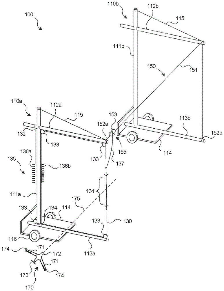
图1图示了根据本技术的特定实施例的代表性系统100,所述系统100被配置为捕捉飞行器(例如,无人驾驶航空器(UAV)170)。飞行器170能够包括机身172、机翼171和推进系统173(例如,引擎驱动的推进器)。飞行器170能够还包括适合于捕获或捕捉飞行器170的一个或更多个捕捉或接合装置174。在一个实施例中,接合装置174能够包括机翼安装的夹子或夹板,而在其他实施例中,接合装置174能够包括其他合适的结构。FIG. 1 illustrates a
系统100被配置为通过与一个或更多个接合装置174可释放地接合而捕捉飞行器170。系统100能够包括两个支撑部110,所述两个支撑部110被图示为第一支撑部110a和与第一支撑部110a间隔开的第二支撑部110b。每个支撑部110a、110b均能够包括对应的直立部分111(被图示为第一直立部分111a和第二直立部分111b)和一个或更多个吊杆部分112。例如,在图1中示出的布置能够包括由第一支撑部110a承载的上吊杆部分112a和下吊杆部分113a以及由第二支撑部110b承载的上吊杆部分112b和下吊杆部分113b。吊杆拉索115相对于各自的支撑部110a、110b稳定上吊杆部分112a、112b。
第一和第二支撑部110a、110b被配置为在地面、船舶甲板或其他表面之上承载或支撑滑架轨道150。滑架轨道150进而支撑滑架153。滑架153能够沿着滑架轨道150沿着大体上直线路径滑动或滚动。支撑部110a、110b中的一个或更多个(例如,第一支撑部110a)被可操作地耦接到柔性捕捉索130,所述柔性捕捉索130被用来捕捉飞行器170。在图1中示出的实施例的一个方面,捕捉索130包括绳、缆或具有接合区域131的其他薄的细长柔性结构,在捕捉操作期间,飞行器170撞击所述接合区域131,并且飞行器170可释放地附接到所述接合区域131。捕捉索130能够在一端处(例如,在第一附接点132处)被连接到第一支撑部110a,然后绕过一系列滑轮133,并且在其另一端处(例如,在第二附接点134处)附接到第一支撑部110a的底座114。系统100能够包括能量吸收器或耗能装置135,所述能量吸收器或耗能装置135被可操作地耦接到捕捉索130,以当飞行器170被捕捉时吸收被飞行器170引导到系统100内的能量。例如,能量吸收器135能够包括一个或更多个弹性构件136(被示为第一弹性构件136a和第二弹性构件136b),诸如橡皮带、弹簧或与捕捉索130轴向连接(并且能够形成捕捉索130的一部分)由此当飞行器170撞击捕捉索130时允许捕捉索130伸长或放出的其他柔性可伸长元件。The first and
如果捕捉索130被允许以不受限制的方式伸长和收缩,那么当飞行器170撞击捕捉索130时捕捉索130将会首先伸长或延伸,并且然后当弹性构件136a、136b收缩时弹回或收缩。为了防止这种结果,系统100能够包括限制滑架153和捕捉索130的运动的特征。例如,限制装置155能够包括限制索137(例如缆、绳或其他合适的元件),所述限制索137被横向地连接到捕捉索130并且在捕捉索130与滑架153之间延伸。当捕捉索130在由进来的飞行器170所施加的力下沿第一方向延伸或伸长时,限制索137沿着滑架轨道150将滑架153例如从第一位置拖曳到第二位置。在滑架沿着滑架轨道150行进结束的时候,滑架153和/或滑架轨道150中的棘轮或锁定机构(在图1中不可见)防止滑架153沿着滑架轨道150向后行进,并且还防止捕捉索130沿第二(相反)方向移动。相应地,限制装置155能够包括限制索137和被可操作地耦接到限制索137的锁定或棘轮机构。限制装置155被定尺寸并且被配置为防止伸长的或放出的捕捉索130允许现在捕捉的飞行器170撞击放置系统100的表面。例如,当限制装置155包括柔性限制索137(如在图1中示出的)时,限制索137的长度能够被定尺寸为使得,当飞行器170在沿着接合区域131的任何位置处被捕捉时,飞行器170的最低部分保持足够高以避免撞击地面。通常,最低部分是与捕捉索130接合的机翼相对的机翼的尖端,但是在其他实施例中,最低部分能够是不同的。限制索137能够在接合区域131(如在图1中示出的)之上被连接到捕捉索130,以减少或消除在捕捉期间与飞行器170和/或捕捉索130的干扰。If
在图1中示出的实施例的特定方面,滑架轨道150具有柔性索151的形式,所述柔性索151在第一附接点152a处被附接到第一支撑部110a,并且在第二附接点152b处被附接到第二支撑部110b。第一和第二支撑部110a、110b然后被牢固地(并且通常可释放地)连接到或向下负重到它们搁置的表面上,以便减少形成滑架轨道150的索151中的松弛。支撑部110a、110b的底座114能够包括轮子116或便于改变系统100的位置的其他元件。In a particular aspect of the embodiment shown in FIG. 1 , the
在操作中,飞行器170沿着飞行路径175接近系统100。在图1中示出的实施例中,接合装置174被安装在机翼171的尖端附近,使得当飞行器170飞入捕捉索130时,接合装置174中的至少一个将飞行器170牢固地但是可释放地固定到捕捉索130。In operation,
在撞击时,飞行器170的动量开始传递到系统100,并且捕捉索130开始延伸、伸长或放出。当捕捉索130延伸时,限制索137沿着滑架轨道150拉动滑架153。当飞行器170停止其向前运动(例如由于充分的动量损失或由于可以包括到达滑架轨道150的末端的其他因素)时,限制装置155(例如,滑架153和/或滑架轨道150中的棘轮或锁定机构)防止滑架153并且因此防止限制索137和捕捉索130收缩。为了释放飞行器170,操作者使接合装置174与捕捉索130分离。能量吸收器135能够被重新设定(例如,通过逐渐释放棘轮装置155并且允许弹性构件136a、136b收缩),并且滑架153和捕捉索130被重新定位用于另一捕捉操作。Upon impact, the momentum of the
如上所述,系统100的一个特征是,滑架轨道150能够包括柔性索151。该特征的一个优点是,系统100能够是重量轻的并且容易被安置。这种系统的潜在缺点是,滑架轨道150能够在被捕捉的飞行器170的重量下下陷。在下面参考图2A-10B描述的实施例能够通过提供防止滑架轨道下陷的刚性滑架轨道和/或压缩构来解决这种属性。As noted above, one feature of
图2A是根据本技术的另一实施例配置的系统200的局部示意的等距图示。系统200能够包括第一和第二支撑部210a、210b,均具有对应的直立部分211a、211b、对应的上吊杆部分212a、212b和对应的底座214。第一支撑部210a能够还包括下吊杆部分213a。滑架轨道250被定位在上吊杆部分212a、212b之间,并且能够包括大体上刚性管道、管或其他刚性构件。系统200能够进一步包括一个或更多个压缩构件217,所述一个或更多个压缩构件217也被连接在第一和第二支撑部210a、210b之间。压缩构件217能够防止被捕捉的飞行器170的重量(a)引起滑架轨道250下陷,和/或(b)朝向彼此拖曳第一和第二支撑部210a、210b。Figure 2A is a partially schematic isometric illustration of a
系统200能够进一步包括滑架253。滑架253能够包括滑架滚轮254,所述滑架滚轮254允许滑架253沿着滑架轨道250滚动。滑架253还能够与用于捕捉飞行器170的捕捉索230接合。捕捉索230能够包括接合区域231,所述接合区域231被定位为与飞行器170接触。在特定实施例中,捕捉索230能够与滑架253可滑动地接合。例如,滑架253能够包括捕捉索230穿过其的环状件。在其他实施例中,滑架253能够包括捕捉索230绕过其的滚轮或滑轮。在又进一步的实施例中,滑架253被固定地附接到捕捉索230。捕捉索230能够绕过由第一支撑部210a承载的多个捕捉索滑轮233,以便被连接到能量吸收器235。能量吸收器235能够允许捕捉索230(例如捕捉索的存储部分)在由飞行器170施加于捕捉索230的力下放出。能量吸收器235能够包括弹簧、橡皮带或阻止放出捕捉索230的其他可伸长或可延伸元件。在特定实施例中,能量吸收器235能够包括弹簧加载的卷筒、或配备有裂缝以将力施加于捕捉索230的卷筒。在特定实施例中,由能量吸收器235施加的力能够改变,例如,如稍后参考图12G进一步详细地描述的。
图2B图示了在飞行器170已经与捕捉索230接合之后的系统200。飞行器170与捕捉索230之间的冲击力引起能量吸收器235延伸或放出捕捉索230,并且引起滑架253沿着滑架轨道250移动,如通过箭头A指示的。FIG. 2B illustrates
图2C图示了在滑架253已经到达滑架轨道250的末端之后的系统200。滑架253中的限制装置255(例如,棘轮)防止滑架253在可以由能量吸收器235施加于捕捉索230的返回力下被向后拉动。压缩构件217(并且滑架轨道250抵抗压缩力的能力)防止或显著限制滑架轨道250下陷的趋势、和/或支撑部210a、210b朝向彼此倾斜或收缩的趋势。支撑部210a、210b的直立部分211a、211b足够高,使得当飞行器170在接合区域231处撞击捕捉索230并且如在图2C中示出的那样悬挂在捕捉索230上时,飞行器170不碰触地面。一旦飞行器170到达在图2C中示出的位置,飞行器170就能够被和缓地降低和释放。在特定实施例中,捕捉索230能够从滑架253被释放以允许飞行器170被和缓地降低。FIG. 2C illustrates
图2D是特定实施例的俯视图,其中系统200由被定位在水292之上的具有甲板291的船舶290承载。在该实施例的特定方面,滑架轨道250能够被配置为允许被捕捉的飞行器170在甲板291之上被移动以便释放,而非在水292之上晃来晃去。相应地,每个支撑部210a、210b能够包括吊杆枢转接头218,所述吊杆枢转接头218允许对应的上吊杆部分212a、212b旋转。此外,滑架轨道253能够在滑架轨道枢转接头256处被连接到吊杆,所述滑架轨道枢转接头256允许滑架轨道253相对于上吊杆部分212a、212b枢转。当第二上吊杆部分212b在船舶的甲板291之上摇摆(如通过箭头B指示的)时,第一上吊杆部分212a以铰接的方式首先顺时针并且然后逆时针(如通过箭头C指示的)移动,以便于第二上吊杆部分212b的运动。这种布置的优点是,它允许飞行器捕捉操作在水292之上并且远离船舶的上层结构发生,同时还允许飞行器170在甲板291之上被容易地移动以便释放。FIG. 2D is a top view of a particular embodiment in which the
图3是系统200的另一实施例的局部示意的图示,所述系统200进一步包括由第二支撑部210b承载的下吊杆部分213b和包括上滑架轨道350a和下滑架轨道350b的滑架轨道布置。对应的滑架353能够包括上部部分354a(例如,第一滚轮或轮子)和下部部分354b(例如,第二滚轮或轮子),所述上部部分354a和下部部分354b中的每一个沿着对应的滑架轨道350a、350b滚动。下部部分354b以大体上类似于在参考图2A描述的那些中的任何一个的方式与捕捉索230接合。当飞行器170与捕捉索230接合时,由于下滑架部分354b沿着下滑架轨道350b行进,捕捉索在上滑架轨道350a与下滑架轨道350b之间的部分保持比在图2C中示出的捕捉索230更直立的取向。这种布置的一个方面是,它能够降低飞行器170以除预期方式之外的任何方式撞击捕捉索230的可能性。换言之,该装置能够使捕捉索230的某些部分(而非接合部分231)避开飞行器170。此外,下滑架轨道350b和第二下吊杆部分213b能够增加整个系统200的刚度。3 is a partially schematic illustration of another embodiment of a
上述实施例的一个特性是,它们具有大体上矩形或盒状形状。在下面参考图4-10B进一步描述的其他实施例中,捕捉系统能够具有大体上三角形形状,并且能够被配置为收缩为用于运输的紧凑布置。A characteristic of the above-described embodiments is that they have a generally rectangular or box-like shape. In other embodiments, described further below with reference to FIGS. 4-10B , the capture system can have a generally triangular shape and can be configured to collapse into a compact arrangement for transportation.
开始图4,根据特定实施例配置的系统400能够包括具有直立部分411的支撑部410,所述直立部分411承载沿第一方向延伸的第一吊杆部分412a和沿不同于第一方向的第二方向延伸的第二吊杆部分412b。系统400能够还包括底座414,所述底座414进而包括第一底座部分424a和第二底座部分424b。底座部分424a、424b能够被设置在对应的吊杆部分412a、412b之下。上滑架轨道450a在第一和第二吊杆部分412a、412b的末端之间延伸,而下滑架轨道450b在第一和第二底座部分424a、424b的末端之间延伸。能够包括上部部分454a(例如,上滚轮)和下部部分454b(例如,下滚轮)的滑架453以适合于捕捉在上面参考图1-3描述的飞行器170的大体上垂直取向承载捕捉索430。4, a
系统400的直立部分411能够包括一对剪式套筒或铰链419,所述对剪式套筒或铰链419中的每一个包括在对应的剪式枢轴421处被枢转地连接到彼此的一对剪式构件420。每个剪式构件420能够在一端处经由枢转接头422被连接到系统400,而在另一端处经由滑动接头423被连接到系统400。这种布置能够允许上吊杆部分412a、412b相对于底座414容易地上下活动。The
在图4中示出的实施例的另一方面,捕捉索430不一定被配置为伸长或被放出。替代地,捕捉索430能够在上滑架部分454a与下滑架部分454b之间具有固定长度。由飞行器170施加于该系统的能量(图3)能够被能量吸收器435吸收,所述能量吸收器435经由吸收器索439被耦接到滑架453。在特定实施例中,能量吸收器435能够包括绞盘438。吸收器索439能够被固定地连接到滑架453(例如,邻近上滑架部分454a),并且能够具有绕过两个吸收器索滑轮440并且绕过能量吸收器435的绞盘438的连续环的形式。绞盘438进而能够被耦接到抵抗或制动装置,例如,消散由飞行器170传递到捕捉索430的能量的磁涡流制动或其他装置。在操作中,当飞行器170与捕捉索430接合时,它沿着对应的上和下滑架轨道450a、450b拉动上和下滑架部分454a、454b,同时上滑架部分454a绕能量吸收绞盘438拉动吸收器索439。这种操作的进一步细节在下面参考图8A-8C进行描述。为了图示的目的,例如被用来竖立和收缩系统400的其他索未在图4中进行示出,并且在下面参考图5进一步描述。In another aspect of the embodiment shown in FIG. 4, the
系统400能够还包括被耦接到底座414或该结构的另一合适部分的一个或更多个定位滚轮、轮子或其他运输特征416。例如,如果风改变方向,运输特征416能够允许系统400被容易地重新取向。一旦系统400处于合适的位置,它就能够被向下打桩或被向下捆绑以防止其在飞行器170的冲击力下移动。底座414的三角形形状能够提供抵抗飞行器170的冲击力的稳定平台。
图5是在图4中示出的系统400的前视图,图示了若干额外特征。例如,图5图示了当系统400处于操作构造时为系统400增添刚性的多条支撑索525。系统400能够在部署绞车560或另一合适的部署致动器的动力下在图5中示出的操作构造与在收缩构造之间交替。部署绞车560能够被耦接到一个或更多个部署索562,所述一个或更多个部署索562绕过一系列部署滑轮561。当被释放时,部署索562允许剪式套筒419收缩。当被缠绕在部署绞车560上,部署索562将剪式套筒419拉动到在图5中示出的直立位置。FIG. 5 is a front view of the
图6是在上面参考图4和图5描述的系统400的实施例的侧视图。图6进一步图示了被用来升起和降低剪式套筒419的部署绞车560、部署索562和部署滑轮561。图6还图示了当能量吸收器索439以连续环的方式绕过绞盘438和吸收器索滑轮440(吸收器索滑轮440中的一个在图6中可见)时的能量吸收器435和能量吸收器索439。这种布置在下面参考图7进一步详细地描述。FIG. 6 is a side view of an embodiment of the
现在参考图7,连续的吸收器索439绕过用于引导的两个吸收器索滑轮440,并且然后被缠绕(例如,多次)在绞盘438上。当滑架453沿着上滑架450a移动时,它绕绞盘438拉动吸收器索439以消散由被捕捉的飞行器施加于系统400的冲击能量。图示这种布置的对应顺序在下面参考图8A-8C进行描述。Referring now to FIG. 7 , the
如在图8A中示出的,飞行器170沿着飞行路径175接近系统400。在图8B中,飞行器170已经与捕捉索接合(在图8B中不可见),其中冲击力沿着上滑架轨道450a拖曳滑架453,如通过箭头A指示的。当滑架453沿着上滑架轨道450a移动时,它绕由吸收器索滑轮440和绞盘438形成的回路拖曳吸收器索439,如通过箭头D指示的。绞盘438如通过箭头E指示的那样旋转并且吸收能量。当飞行器170已经损失其向前动量时和/或当滑架453到达上滑架轨道450a的末端时,滑架453停止。限制装置(例如,由滑架453和/或上滑架轨道450a承载的棘轮或任何其他合适装置)防止滑架453弹回。替代地,绞盘438或棘轮机构在能量吸收器435处的摩擦能够防止这样的弹回运动,并且因此能够操作为限制装置。As shown in FIG. 8A ,
图8C图示了在飞行器170已经被成功捕捉之后的系统400。由于飞行器170处于该位置中,部署绞车560能够被释放或被停用,从而允许剪式套筒419至少部分地收缩并降低飞行器170,如通过箭头F指示的。操作者然后从系统400释放飞行器170。部署绞车560然后能够被重新激活,以将上滑架轨道450a升到操作位置,如通过箭头G指示的。FIG. 8C illustrates
除相对于下滑架轨道450b移动上滑架轨道450a以释放被捕捉的飞行器170之外,部署绞车560还能够被用来收缩和竖立系统400。例如,如在图9A中的侧视图中示出的,系统400最初能够能够被置于收缩位置中,其中上滑架轨道450a被定位在下滑架轨道450b附近,并且捕捉索430松弛。在图9B中,部署绞车560已经被激活以缠绕部署索562,从而竖立剪式构件420并且升起上滑架轨道450a。在图9C中,系统400已经被完全竖立,其中捕捉索430现在在上滑架部分454a与下滑架部分454b被张紧(或被部分地张紧)。上述顺序能够被逆转,以使系统400返回到在图9A中示出的收缩构造。In addition to moving
现在参考图10A,系统400能够被进一步收缩以便存储和/或运输。具体地,上滑架轨道450a能够包括可分开接头1057,所述可分开接头1057允许上滑架轨道450a被分为两个节段1080a、1080b,所述两个节段1080a、1080b然后被移动分开并且远离彼此(如通过箭头H指示的),并且然后被旋转为与对应的吊杆部分对齐(如通过箭头I指示的)。在图10A的顶视图中不可见的下滑架轨道450b能够以类似的方式被拖曳。Referring now to FIG. 10A, the
在图10B中,滑架轨道、吊杆部分和剪式构件420能够朝向彼此收缩,如通过箭头J指示的。在该实施例的又一方面,吊杆部分和/或滑架轨道能够被向内套叠(如通过箭头K指示的),以进一步减小被系统400占据的体积,为运输和/或存储作准备。In FIG. 10B , the carriage track, boom portion and
图11A-11G图示了根据本技术的代表性实施例的包括被配置为在捕捉之后防止或至少限制飞行器170的运动的限制装置1150的系统1100。在一个代表性实施例中,系统1100能够包括支撑部110(例如,单个支撑部),所述支撑部110具有直立部分111、上吊杆部分112和下吊杆部分113。支撑部110以大体上类似于在上面参考图1讨论的布置承载捕捉索130。相应地,捕捉索130能够在第一附接点132和第二附接点134处被附接到支撑部110,并且能够在两个附接点之间绕过一系列滑轮133。捕捉索130包括接合区域131,在捕捉操纵期间飞行器170被引导到所述接合区域131内。能量吸收器135(例如,包括第一和第二弹性构件136a、136b,诸如橡皮带)吸收由飞行器170施加于捕捉索130的能量。11A-11G illustrate a
限制装置1150被配置为至少暂时中止当能量吸收器135释放在捕捉操作期间最初吸收的能量时飞行器170要不然将会经历的弹回运动。在代表性实施例中,限制装置1150包括限制索1156,所述限制索1156被耦接到捕捉索130。例如,限制索1156能够被连接到捕捉索130,并且从捕捉索130横向地延伸。在特定实施例中,限制索1156在接合区域131之下被连接到捕捉索130,例如以减少限制索1156对成功接合飞行器170与接合区域131的操作的任何影响。在其他实施例中,限制索1156能够在其他位置处被连接到捕捉索。
限制装置1150能够进一步包括限制支撑部1151,所述限制支撑部1151承载并且引导限制索1156。例如,限制支撑部1151能够承载一个或更多个支撑臂1152(在图11A中示出了所述支撑臂1152中的两个),所述支撑臂1152进而例如经由滑轮托架1154支撑限制索滑轮1155。托架1154能够承载相对硬的缓冲元件(例如,弹簧)以例如在捕捉操作期间吸收由限制索滑轮1155施加的力。支撑臂1152能够被调整以改变限制索1156的高度和/或取向,例如以减少捕捉索130与限制索1156之间的干扰和/或调整飞行器170在捕捉期间相距地面的高度。限制索1156绕过限制索滑轮1155,并且被附接到收缩构件1157。限制索滑轮1155能够包括可释放的单向或锁定机构,当所述可释放的单向或锁定机构被接合时,所述可释放的单向或锁定机构允许限制索1156沿一个方向但不沿两一个方向绕过滑轮。收缩构件1157能够包括弹簧或在捕捉操作期间吸收限制索1156中的松弛的其他可伸缩弹性构件。收缩构件1157能够具有相对低的弹簧常数,以便在飞行器170与捕捉索130接合之前不引起捕捉索130显著偏离在图11A中示出的垂直位置。The
限制装置1150能够还包括绞车1158,所述绞车1158被可操作地耦接到限制索滑轮1155。例如,绞车1158能够经由绞车索1160被附接到滑轮托架1154,所述绞车索1160通过一个或更多个绞车索滑轮1159来引导。绞车1158和绞车索1160能够在捕捉之前将滑轮托架1154和限制索滑轮1155保持在图11A中示出的位置。在捕捉之后,绞车1158能够被用来可控制地释放由能量吸收器135吸收的能量,并且定位飞行器170以便从捕捉索130释放,如在下面参考图11B-11D进一步讨论的。The
在图11B中,飞行器170已经接合捕捉索130,引起捕捉索130侧向地偏离在图11A中示出的位置。能量吸收器135开始吸收由飞行器170施加于捕捉索130的能量,如通过弹性构件136a、136b的伸长状态示意地指示的。当飞行器170侧向地偏离捕捉索130时,收缩构件1157拉动限制索1156以吸收限制索1156中的松弛。相应地,收缩构件1157能够具有强的收缩力以跟上被捕捉的飞行器170的运动,而不使捕捉索130过度偏离其最初的大体上垂直位置,如在上面参考图11A讨论的。In FIG. 11B ,
在图11C中,飞行器170已经到达其行进的末端。能量吸收器135已经到达其用于操纵的峰值能量吸收点,并且锁定滑轮1155已经锁定限制索1156,从而防止捕捉索130返回到其在图11A中示出的大体上垂直位置。收缩构件1157已经进一步收缩(例如,至其最大收缩状态)。然而,因为限制索滑轮1155已经锁定限制索1156,所以收缩构件1157不提供将被捕捉的飞行器170保持在图11C中示出的位置所需的力。替代地,锁定滑轮1155和限制支撑部1151抵抗由能量吸收器135施加于捕捉索130的力。在该实施例的特定方面,由支撑部110承载的一个或更多个滑轮133能够包括可释放锁定机构。例如,当飞行器170到达其捕捉轨迹的末端时,在上和下吊杆部分112、113的末端处的两个滑轮(通过参考数字133a、133b来识别)能够可释放地锁定到捕捉索130上。这种布置能够显著减少当被捕捉的飞行器170处于在图11C中示出位置并且能量吸收器135保持被吸收的要不然将会应用于横向延伸的捕捉索130的捕捉能量时在支撑部110上的侧向力。这种布置还能够减少由限制装置1150承受的力。In FIG. 11C ,
图11D图示了用于可控制地释放由能量吸收器135存储的能量并且定位飞行器170使得其能够容易从捕捉索130被释放的代表性过程。在该实施例的特定方面,绞车1158可控制地放出绞车索1160,从而允许滑轮托架1154和(仍然被锁定的)限制索滑轮1155从第一位置朝向支撑部110移动到第二位置。当限制索滑轮1155朝向支撑部110移动时,能量吸收器135中的张力释放,使得能量吸收器135返回到在图11A中示出的状态。一旦捕捉索130返回到(或靠近)其垂直位置,并且绞车索1160是松弛的(或近似松弛的),飞行器170能够容易从捕捉索130被移除。如在图11D中示出的,捕捉索130的接合区域131被蓄意定尺寸为使得,(a)被捕捉的飞行器170在捕捉过程期间不接触地面,以及(b)操作者能够容易到达被捕捉的飞行器170以便释放。如果飞行器170对于操作者来说太高以至于不能容易到达,那么操作者能够使用提升机来到达它,或捕捉索130能够被降低。FIG. 11D illustrates a representative process for controllably releasing energy stored by
一旦被捕捉的飞行器170从捕捉索130被释放,限制索滑轮1155的锁定机构就被释放,并且绞车1158被激活以将托架1154、限制滑轮1155、限制索1156和收缩构件1157返回到在图11A中示出的构造。系统1100然后准备好下一次飞行器捕捉操作。Once captured
图11E-11G图示了根据本技术的其他实施例的利用滑块1182来控制限制索1156的运动的布置。图11E图示了在接合区域131之下被连接到捕捉索130的限制索。图11E还以虚线的方式图示了限制索1156被附接到捕捉索130的实施例,其中滑块1182被设置在接合区域131之上。将附接定位在限制索1156与捕捉索130之间,远离接合区域131的显著距离能够降低限制索1156干扰飞行器170的捕捉的可能性。然而,限制索1156中的张力可以在飞行器170被捕捉之前引起滑块1182朝向接合区域131移动。具体地,当滑块1182被定位在接合区域13之下时,限制索1156中的张力可以引起滑块182沿着捕捉索130朝向接合区域131向上升起。当滑块1182被定位在接合区域13之上时,限制索1156中的可能通过重力辅助的张力能够引起滑块1182朝向接合区域131向下移动。相应地,系统1100能够包括用于暂时将滑块1182保持在适当位置直至飞行器170接合捕捉索的布置,如在下面参考图11F-11G进一步详细地讨论的。11E-11G illustrate
现在参考图11F,上滑轮133能够通过滑轮支撑部1180和对应的支撑臂1181相对于支撑部112被支撑。滑轮支撑部1180能够包括有眼螺栓,并且支撑臂1181能够包括缆或托架。机械保险丝1184被连接在滑轮支撑部1180与滑块1182之间,以在捕捉之前将滑块1182保持在适当位置。捕捉索130能够包括障碍物1183,所述障碍物1183太大以至于不能穿过滑块1182中的捕捉索130穿过的开口。在捕捉之前,机械保险丝1184将滑块1182保持在图11F中示出的位置。在捕捉期间,飞行器170(在图11F中不可见)拉动捕捉索130,从而引起障碍物1183将向下力施加在滑块1182上。向下力引起机械保险丝1184破坏,从而允许滑块1182沿着捕捉索130自由移动。Referring now to FIG. 11F ,
图11G图示了在飞行器170已经接合捕捉索130之后的系统1100。由飞行器施加于捕捉索130的力已经引起障碍物1183与滑块1182接合,从而引起机械保险丝1184破坏。在特定实施例中,机械保险丝1184能够包括相对于弱的束线带或足以使滑块1182保持静止但是在由障碍物1183施加于滑块1182的力下破坏的其他结构。由限制索1156施加的力引起滑块1182沿着捕捉索130朝向飞行器170移动。当该系统静止时,滑块1182将会被定位在飞行器170的接合装置174正上方。如果滑块1182最初被定位在接合区域131之下(如在图11E中示出的),与在图11F和11G中示出的类似的布置能够应用于在图11E中示出的下滑轮133。任一布置的预期结果是,限制索1156被定位为不妨碍接合区域131和飞行器170,直至飞行器170已经被成功捕捉。FIG. 11G illustrates
在上面参考图11A-11G描述的上述实施例中的至少一些的一个特征是,限制装置1150能够操作为当飞行器170经历捕捉操作时控制飞行器170运动。这样一来,除经由与接合装置174的预期接触之外,飞行器170更不可能接触或干扰捕捉索130。此外,飞行器170更不可能经历突然的减速,和/或与周围的设备或地面冲突,并且因此能够显著延长飞行器170的使用寿命。It is a feature of at least some of the above embodiments described above with reference to FIGS. 11A-11G that the
图12A-12G示意地图示了具有着陆装置(例如,柔性、弹性着陆装置)1260的系统1200,所述着陆装置1260被定位为在飞行器170与捕捉索130接合之后缓和飞行器170的冲击。图12A是飞行器170接近系统1200的等距图示,所述接近系统1200包括单个支撑部110,所述支撑部110具有大体上类似于在上面参考图1描述的构造。着陆装置1260被定位为大体上沿着飞行路径175经过支撑部110。一般来说,着陆装置1260被定位在捕捉索130的接合部分131之下,以便当飞行器170与捕捉索130接合时在飞行器170之下。12A-12G schematically illustrate
图12B是当飞行器170接近捕捉索130时飞行器170的简化侧视图。为了清楚的目的,在图12A中示出的能量吸收器装置135未在图12B中示出。如在图12B中示出的,着陆装置1260被定位为沿着飞行路径175超过捕捉索130选定的距离,以便在捕捉操作结束的时候接收飞行器170。FIG. 12B is a simplified side view of
在图12C中,飞行器170已经与捕捉索130接合,并且沿着飞行路径175侧向拉动捕捉索130。捕捉索130绕过的滑轮133中的每一个能够包括限制装置(例如,锁定器或棘轮),所述限制装置允许滑轮133沿便于将捕捉索130延伸到在图12C中示出的位置所需的方向旋转,并且阻止或防止捕捉索130沿相反方向移动。相应地,当飞行器170处于在图12C中示出的位置时,限制装置能够锁定捕捉索130的运动。此时,飞行器170沿着由捕捉索130在飞行器170与上吊杆部分112之间的长度限定的弧线C朝向着陆装置1260降落。在图12D中,飞行器170已经在着陆装置1260上实现静止,并且准备好从捕捉索130被释放。In FIG. 12C ,
着陆装置1260能够被具体配置为降低或消除当飞行器170着陆时对飞行器170造成损坏的可能性。例如,现在参考图12E,着陆装置1260(在平面图中示出)能够包括当飞行器170实现静止时约束和/或缓和飞行器170的运动的凹处、容座、凹形区域或凹陷。例如,着陆装置1260能够包括执行这种功能的大体上圆形或椭圆形凹陷1261a(以虚线示出)。在另一实施例中,例如,其中飞行器170的位置和取向从一次捕捉到下一次捕捉可靠地重复,代表性凹陷1261b(以实线示出)能够具有对应于当飞行器冲击着陆装置1260时飞行器的形状和取向的形状。
图12F是大体上沿着图12E的线12F-12F获得的着陆装置1260的局部示意的横截面图示。如在图12F中示出的,着陆装置1260能够包括底座1262和环绕或至少部分地环绕凹形区域1261的侧壁1264。在特定实施例中,侧壁1264能够包括多个部分,例如,第一部分1263a和第二部分1263b。第一部分1263a能够具有一种组成,而第二部分1263b能够具有另一种组成。在特定实施例中,第一部分1263a能够是可充气的,并且能够包括一个或更多个气体(例如,空气)囊。第二部分1263b能够包括泡沫或另一可压缩弹性材料。底座1262能够还包括可压缩材料,例如,泡沫或充满气体的囊。Figure 12F is a partially schematic cross-sectional illustration of
图12G是根据本技术的另一实施例的配置的增添能量吸收器装置1235的系统1200的局部示意的图示。在该实施例的一个方面,能量吸收器装置1235能够与控制器1270(例如,基于计算机的控制器)通信,以调整能量吸收器装置1235吸收由UAV 170与捕捉索130之间的冲击产生的能量的方式。例如,在特定实施例中,能量吸收器装置1235能够包括当飞行器与捕捉索130接合时将变化的破坏力施加于捕捉索130的计算机控制的破坏。通过改变由能量吸收器装置1235施加的破坏力,系统1200能够适应具有不同尺寸、重量和/或速度的飞行器。具体地,着陆装置1260可以被定位为远离支撑部110和捕捉索130选定的距离。如果飞行器170的动量能够从一种飞行器到另一种飞行器和/或从一种飞行到另一种飞行发生改变,那么当被捕捉的时候飞行器170行进的距离也会改变。因此,飞行器可以越过或未达着陆装置1260。具体地,当被耦接到控制器1270时,能量吸收器装置1235能够解决这种潜在的问题。具体地,控制器1270能够从飞行器170和/或其他源接收指示飞行器的重量和速度的数据。控制器1270能够利用该信息根据施加于捕捉索130的时间来确定破坏力,使得当其向前行进停止时飞行器在着陆装置1260的正上方。在特定实施例中,破坏能够包括轮子或一系列轮子,所述轮子或一系列轮子在捕捉索130上提供可变阻力,以便从一次捕捉操作到另一次捕捉操作和/或在各个捕捉操作的过程中改变破坏力。上述布置的优点是,它能够允许具有各种重量和速度的飞行器利用单个捕捉装置1200而不必对捕捉装置1200进行手动调整。12G is a partially schematic illustration of a
在上面参考图12A-12G描述的上述实施例中的至少一些的一个特征是,它们能够相对简单地实施。例如,着陆装置1260能够在很大程度上可充气,并且相应地能够容易被收缩以便存储。此外,着陆装置1260能够具有可以更不易于磨损和疲劳的简单机械结构。相反,在上面参考图1-11D描述的本技术的实施例不需要被捕捉的飞行器与着陆装置之间的冲击,并且相应地,可以具有可能由此类接触潜在地引起的意外损坏的降低的趋势。A feature of at least some of the above-described embodiments described above with reference to FIGS. 12A-12G is that they are relatively simple to implement. For example, the
根据上述内容,应认识到,为了图示的目的,本技术的具体实施例已经在本文中进行描述,但是可以进行各种更改而不偏离所公开的技术。例如,在特定实施例中,上述能量吸收器能够包括橡皮带索或其他柔性且可伸长元件,而在其他实施例中,合适的能量吸收器能够包括缠绕在轮子上的索,所述轮子包括吸收能量的阻力元件、和/或防止索反绕或要不然弹回直至装置被重新设定的棘轮机构。在上面参考图11A-11D描述的限制装置的实施例能够包括铰接布置的支撑臂1152。在其他实施例中,限制装置能够具有固定的支撑臂。在特定实施例中,通过上述装置中的任何一个捕捉的飞行器会是图1中示出的形状和构造,并且在其他实施例中,能够具有其他布置。在特定实施例的背景下描述的描述的技术的某些方面可以在其他实施例中被组合或被省掉。例如,在上面参考图4-10B描述的三角形布置能够包括大体上类似于在上面参考图1描述的柔性滑架轨道。由滑架轨道承载的棘轮或其他运动阻止器(如在图8B的背景下描述的)能够应用于除参考图8B描述的那些之外的实施例。取决于实施例,代表性系统能够包括滑架轨道而不包括限制装置、包括限制装置而不包括滑架轨道、既包括限制装置也包括滑架轨道、或既包括限制装置也不包括滑架轨道。特定实施例能够包括具有或不具有限制装置的柔性着陆装置。其他实施例能够包括柔性着陆装置和一个或更多个滑架轨道。在上面参考图2D的枢转布置能够应用于在其他实施例中的其他布置,例如,在上面参考图4-10B描述的布置。在上面参考图9A-10B描述的收缩布置的方面能够应用于在其他实施例中的其他布置,例如,在上面参考图1-3和11A-12F描述的布置。另外,虽然与本技术的某些实施例相关的优点已经在那些实施例的背景下进行描述,但是其他实施例也可以表现出此类优点,并且不是所有实施例都必然表现出此类优点以落入本技术的范围内。相应地,本公开和相关的技术能够包含在本文中未专门示出或描述的其他实施例。From the foregoing it should be appreciated that specific embodiments of the technology have been described herein for purposes of illustration, but that various changes may be made without departing from the technology disclosed. For example, in certain embodiments, the energy absorber described above can comprise a rubber cord or other flexible and extensible element, while in other embodiments a suitable energy absorber can comprise a cord wrapped around a wheel that A resistance element that absorbs energy, and/or a ratchet mechanism that prevents the cable from rewinding or otherwise bouncing back until the device is reset is included. Embodiments of the restraint device described above with reference to FIGS. 11A-11D can include a
以引用的方式被并入本文的资料中的任何一个在一定程度上与本公开冲突,本公开进行控制。To the extent any of the materials incorporated herein by reference conflict with the present disclosure, the present disclosure controls.
Claims (31)
Priority Applications (1)
| Application Number | Priority Date | Filing Date | Title |
|---|---|---|---|
| CN202010025971.7A CN111232235B (en) | 2014-11-20 | 2015-11-19 | Capture device for unmanned aerial vehicle including track-borne capture line and related systems and methods |
Applications Claiming Priority (6)
| Application Number | Priority Date | Filing Date | Title |
|---|---|---|---|
| US201462082471P | 2014-11-20 | 2014-11-20 | |
| US62/082,471 | 2014-11-20 | ||
| US14/939,893 | 2015-11-12 | ||
| US14/939,893 US9896222B2 (en) | 2014-11-20 | 2015-11-12 | Capture devices for unmanned aerial vehicles, including track-borne capture lines, and associated systems and methods |
| CN201510801838.5A CN105620779B (en) | 2014-11-20 | 2015-11-19 | Capture device for unmanned aerial vehicle including orbital capture cable and related systems and methods |
| CN202010025971.7A CN111232235B (en) | 2014-11-20 | 2015-11-19 | Capture device for unmanned aerial vehicle including track-borne capture line and related systems and methods |
Related Parent Applications (1)
| Application Number | Title | Priority Date | Filing Date |
|---|---|---|---|
| CN201510801838.5A Division CN105620779B (en) | 2014-11-20 | 2015-11-19 | Capture device for unmanned aerial vehicle including orbital capture cable and related systems and methods |
Publications (2)
| Publication Number | Publication Date |
|---|---|
| CN111232235A CN111232235A (en) | 2020-06-05 |
| CN111232235B true CN111232235B (en) | 2023-05-26 |
Family
ID=54695587
Family Applications (2)
| Application Number | Title | Priority Date | Filing Date |
|---|---|---|---|
| CN202010025971.7A Active CN111232235B (en) | 2014-11-20 | 2015-11-19 | Capture device for unmanned aerial vehicle including track-borne capture line and related systems and methods |
| CN201510801838.5A Active CN105620779B (en) | 2014-11-20 | 2015-11-19 | Capture device for unmanned aerial vehicle including orbital capture cable and related systems and methods |
Family Applications After (1)
| Application Number | Title | Priority Date | Filing Date |
|---|---|---|---|
| CN201510801838.5A Active CN105620779B (en) | 2014-11-20 | 2015-11-19 | Capture device for unmanned aerial vehicle including orbital capture cable and related systems and methods |
Country Status (5)
| Country | Link |
|---|---|
| US (3) | US9896222B2 (en) |
| EP (3) | EP3536613B1 (en) |
| CN (2) | CN111232235B (en) |
| AU (1) | AU2015258322B2 (en) |
| IL (2) | IL242672B (en) |
Families Citing this family (41)
| Publication number | Priority date | Publication date | Assignee | Title |
|---|---|---|---|---|
| WO2010138265A1 (en) | 2009-04-24 | 2010-12-02 | Insitu, Inc. | Systems and methods for recovering and controlling post-recovery motion of unmanned aircraft |
| US8944373B2 (en) | 2010-09-27 | 2015-02-03 | Insitu, Inc. | Line capture devices for unmanned aircraft, and associated systems and methods |
| US10569868B2 (en) | 2013-04-02 | 2020-02-25 | Hood Technology Corporation | Multicopter-assisted system and method for launching and retrieving a fixed-wing aircraft |
| US10583920B2 (en) * | 2013-04-02 | 2020-03-10 | Hood Technology Corporation | Multicopter-assisted system and method for launching and retrieving a fixed-wing aircraft |
| US10414493B2 (en) * | 2014-07-11 | 2019-09-17 | Aerovel Corporation | Apparatus and method for automated launch, retrieval, and servicing of a hovering aircraft |
| US10399674B2 (en) | 2014-07-28 | 2019-09-03 | Insitu, Inc. | Systems and methods countering an unmanned air vehicle |
| US9896222B2 (en) | 2014-11-20 | 2018-02-20 | Insitu, Inc. | Capture devices for unmanned aerial vehicles, including track-borne capture lines, and associated systems and methods |
| SG11201703804UA (en) * | 2014-11-27 | 2017-06-29 | Singapore Tech Aerospace Ltd | Apparatus and method for launch and recovery of an unmanned aerial vehicle |
| US10518902B2 (en) * | 2015-03-13 | 2019-12-31 | Lockheed Martin Corporation | UAV capture system |
| US10933997B2 (en) | 2015-10-02 | 2021-03-02 | Insitu, Inc. | Aerial launch and/or recovery for unmanned aircraft, and associated systems and methods |
| US10752357B2 (en) | 2016-03-22 | 2020-08-25 | Hood Technology Corporation | Rotorcraft-assisted system and method for launching and retrieving a fixed-wing aircraft into and from free flight |
| US10407181B2 (en) | 2016-06-27 | 2019-09-10 | Insitu, Inc. | Locking line capture devices for unmanned aircraft, and associated systems and methods |
| US10696420B2 (en) | 2016-08-17 | 2020-06-30 | Hood Technology Corporation | Rotorcraft-assisted system and method for launching and retrieving a fixed-wing aircraft into and from free flight |
| JP6843248B2 (en) * | 2016-09-21 | 2021-03-17 | ジップライン インターナショナル インコーポレイテッド | Automatic recovery system for unmanned aerial vehicles |
| CN106628224A (en) * | 2016-12-15 | 2017-05-10 | 南京航空航天大学 | Rotary rope hook recovery device based on water turbine |
| US11204612B2 (en) | 2017-01-23 | 2021-12-21 | Hood Technology Corporation | Rotorcraft-assisted system and method for launching and retrieving a fixed-wing aircraft |
| US11230389B2 (en) | 2017-02-28 | 2022-01-25 | Lockheed Martin Corporation | System and method of blade-tip facilitated aircraft capture |
| US11524797B2 (en) | 2017-05-11 | 2022-12-13 | Hood Technology Corporation | Aircraft-retrieval system |
| US10988257B2 (en) | 2017-05-11 | 2021-04-27 | Hood Technology Corporation | Aircraft-retrieval system |
| US10767682B2 (en) | 2017-06-29 | 2020-09-08 | Insitu, Inc. | Frangible fasteners with flexible connectors for unmanned aircraft, and associated systems and methods |
| US10611498B2 (en) * | 2017-08-24 | 2020-04-07 | Aurora Flight Sciences Corporation | Rail recovery system for aircraft |
| US11667398B2 (en) | 2017-09-06 | 2023-06-06 | Hood Technology Corporation | Multicopter-assisted systems and methods for launching and retrieving a fixed-wing aircraft into and from free flight |
| US11027844B2 (en) | 2017-09-06 | 2021-06-08 | Hood Technology Corporation | Rotorcraft-assisted system for launching and retrieving a fixed-wing aircraft into and from free flight |
| US11414187B2 (en) | 2017-09-06 | 2022-08-16 | Hood Technology Corporation | Parasail-assisted systems and methods for launching and retrieving a fixed-wing aircraft into and from free flight |
| US11312492B1 (en) | 2017-11-09 | 2022-04-26 | Hood Technology Corporation | Rotorcraft-assisted systems and methods for launching and retrieving a fixed-wing aircraft into and from free flight |
| US10577105B2 (en) * | 2018-02-19 | 2020-03-03 | Wing Aviation Llc | Package loading mechanism |
| US11142339B2 (en) | 2018-05-04 | 2021-10-12 | Insitu, Inc. | Launch and/or recovery for unmanned aircraft and/or other payloads, including via parachute-assist, and associated systems and methods |
| US11066185B2 (en) | 2018-05-04 | 2021-07-20 | Insitu, Inc. | Launch and/or recovery for unmanned aircraft and/or other payloads, including via parachute-assist, and associated systems and methods |
| CN108688828A (en) * | 2018-05-23 | 2018-10-23 | 河南卫华特种车辆有限公司 | A kind of movable unmanned helicopter high-altitude reclaimer |
| US10800547B1 (en) * | 2018-07-25 | 2020-10-13 | The United States Of America, As Represented By The Secretary Of The Navy | Unmanned aerial vehicle (UAV) recovery system |
| US11518511B2 (en) * | 2019-03-06 | 2022-12-06 | Insitu, Inc. | Unmanned aerial vehicle (UAV) recovery |
| US11235892B2 (en) | 2019-05-22 | 2022-02-01 | Hood Technology Corporation | Aircraft retrieval system and method |
| US11117681B2 (en) * | 2019-07-17 | 2021-09-14 | The Boeing Company | Hover flight test system for aircraft |
| US11667396B2 (en) * | 2020-01-13 | 2023-06-06 | Insitu, Inc. | Methods and apparatus to stabilize and recover unmanned aerial vehicles (UAVs) |
| CN112678197B (en) * | 2021-01-19 | 2023-07-28 | 西安爱生技术集团有限公司 | Unmanned aerial vehicle arresting rope herringbone supporting structure and arresting system and method |
| UA125842C2 (en) | 2021-02-17 | 2022-06-15 | Олександр Володимирович Степура | Device for catching and launching an unmanned aircraft |
| US12134466B2 (en) * | 2021-08-09 | 2024-11-05 | Insitu, Inc. | Unmanned aerial vehicles including wing capture devices and related methods |
| CN114013633B (en) * | 2021-11-03 | 2022-08-12 | 国网安徽省电力有限公司蚌埠供电公司 | A UAV with a landing buffer structure |
| CN114620243B (en) * | 2022-05-12 | 2022-09-06 | 四川腾盾科技有限公司 | Intelligent take-off and landing capturing system for aircraft |
| US20250340315A1 (en) * | 2022-06-02 | 2025-11-06 | Nippon Telegraph And Telephone Corporation | Landing assist device and landing assist method |
| WO2024035714A1 (en) * | 2022-08-09 | 2024-02-15 | Pete Bitar | Compact and lightweight drone delivery device called an arcspear electric jet drone system having an electric ducted air propulsion system and being relatively difficult to track in flight |
Citations (5)
| Publication number | Priority date | Publication date | Assignee | Title |
|---|---|---|---|---|
| US2435197A (en) * | 1944-10-04 | 1948-02-03 | James H Brodie | Landing and launching apparatus for aircraft |
| GB2231011A (en) * | 1989-05-03 | 1990-11-07 | Marconi Gec Ltd | Aircraft capture system |
| US6264140B1 (en) * | 1999-06-08 | 2001-07-24 | Mcgeer Brian T. | Method for retrieving a fixed-wing aircraft without a runway |
| CN102625766A (en) * | 2009-04-24 | 2012-08-01 | 英西图公司 | Systems and methods for recovering and controlling post-recovery motion of unmanned aircraft |
| CN104058100A (en) * | 2014-06-23 | 2014-09-24 | 杨举 | Device for launching and landing aircrafts |
Family Cites Families (273)
| Publication number | Priority date | Publication date | Assignee | Title |
|---|---|---|---|---|
| US1624188A (en) | 1927-04-12 | Airplanes eeom and upon suspended | ||
| USRE16613E (en) | 1927-05-03 | Safety hook | ||
| USRE25406E (en) | 1963-06-25 | Aircraft arresting system | ||
| US2735391A (en) | 1956-02-21 | H buschers | ||
| US1317631A (en) | 1919-09-30 | kinser | ||
| US965881A (en) | 1909-12-03 | 1910-08-02 | George Otis Draper | Landing and starting apparatus for aeroplanes. |
| US968339A (en) | 1910-02-28 | 1910-08-23 | Gerald Geraldson | Aeroplane launcher and lander. |
| US975953A (en) | 1910-03-05 | 1910-11-15 | Iskander Hourwich | Aerial projecting apparatus. |
| US1164967A (en) | 1913-10-01 | 1915-12-21 | James M Thorp | Aeroplane alighting and launching apparatus. |
| US1144505A (en) * | 1914-02-18 | 1915-06-29 | Frank Steffan | Aerial landing and launching appliance. |
| US1428163A (en) | 1917-06-23 | 1922-09-05 | James B Harriss | Launching and landing of aeroplanes |
| US1383595A (en) | 1920-02-25 | 1921-07-05 | Johnny S Black | Airplane landing and launching mechanism |
| US1384036A (en) | 1920-12-27 | 1921-07-12 | Anderson Gustaf | Device for launching aeroplanes from ships |
| US1716670A (en) | 1922-06-27 | 1929-06-11 | Lawrence Sperry Aircraft Compa | Device for launching and landing aeroplanes from and upon suspended positions |
| US1499472A (en) | 1922-07-14 | 1924-07-01 | Hazen C Pratt | Airplane-landing mechanism |
| US1738261A (en) | 1922-07-24 | 1929-12-03 | Willis B Perkins | Aeroplane-handling structure |
| US1816976A (en) | 1922-08-03 | 1931-08-04 | Eclipse Machine Co | Engine starting device for aeroplanes |
| US1532736A (en) | 1923-02-26 | 1925-04-07 | Flannery Bolt Co | Stay bolt for boilers |
| US1530010A (en) | 1924-10-01 | 1925-03-17 | Neilson Albert Howard | Safety hook |
| US1556348A (en) | 1925-02-14 | 1925-10-06 | Curtiss Aeroplane & Motor Co I | Aeroplane landing gear |
| US1869506A (en) | 1925-10-23 | 1932-08-02 | Holden C Richardson | Method of and apparatus for mooring an airplane while in flight to another aircraft |
| US1634964A (en) | 1925-12-29 | 1927-07-05 | Joseph A Steinmetz | Mooring dirigible aircraft |
| US1731091A (en) | 1926-08-05 | 1929-10-08 | Belleville Harry Clayton | Aircraft landing |
| US1749769A (en) | 1927-03-31 | 1930-03-11 | Fairchild Airplane Mfg Corp | Airplane-wing connection |
| US1712164A (en) | 1927-04-01 | 1929-05-07 | Peppin Joseph | Antiaircraft screen |
| US1686298A (en) | 1927-09-10 | 1928-10-02 | George E Ginter | Air or seaplane station |
| US1748663A (en) | 1927-09-20 | 1930-02-25 | Charles B Scoville Jr | Method and means for landing and launching aircraft and aircraft freight |
| US1680473A (en) | 1927-11-23 | 1928-08-14 | Parker Orin | Aeroplane landing and launching device |
| US1756747A (en) | 1928-06-12 | 1930-04-29 | Holland Lionel | Aeroplane-landing means |
| US1737483A (en) | 1928-09-18 | 1929-11-26 | Nicholas J Verret | Take-off and landing apparatus for aeroplanes |
| US1777167A (en) | 1928-11-09 | 1930-09-30 | Forbes William Archib Davidson | Apparatus for launching aircraft |
| US1825578A (en) | 1930-01-02 | 1931-09-29 | Cernuda Antonio | Airplane |
| US1836010A (en) | 1930-05-02 | 1931-12-15 | Constant A Audrain | Airplane landing and launching mechanism |
| US1842432A (en) | 1930-08-02 | 1932-01-26 | Samuel A Stanton | Landing and take-off apparatus for airplanes |
| US1925212A (en) | 1930-09-26 | 1933-09-05 | Arthur A Johnson | Means for facilitating the takingoff and landing of aircraft and refueling the same |
| US1940030A (en) | 1931-02-02 | 1933-12-19 | Arthur A Johnson | Means for facilitating the takingoff and landing of aircraft and refueling the same |
| US1912723A (en) | 1931-03-23 | 1933-06-06 | Willis B Perkins Jr | Airplane landing and launching appliance |
| US1892357A (en) | 1931-04-27 | 1932-12-27 | Edward E Moe | Airplane catapult |
| US1960264A (en) | 1931-10-11 | 1934-05-29 | Heinkel Ernst | Catapult for launching aeroplanes |
| US1909445A (en) | 1931-11-23 | 1933-05-16 | Hazel B Tidland | Parachute |
| US2211089A (en) | 1938-03-29 | 1940-08-13 | Curtiss Wright Corp | Wing and fuselage construction |
| US2515205A (en) | 1938-12-30 | 1950-07-18 | Fleux Jean | Catapult device for launching aerial machines |
| FR854371A (en) | 1938-12-30 | 1940-04-11 | Schneider & Cie | Improvements to catapulting devices |
| US2286381A (en) | 1939-03-14 | 1942-06-16 | Rubissow George Alexis | Method and device for forced takeoff and forced landing of airplanes and airships |
| US2296988A (en) | 1940-08-31 | 1942-09-29 | Waldemar A Endter | Hook type rotary latch |
| US2401853A (en) | 1941-06-23 | 1946-06-11 | Lockheed Aircraft Corp | Aerial torpedo |
| US2365827A (en) | 1941-08-05 | 1944-12-26 | Wingfoot Corp | Rigid airship |
| US2333559A (en) | 1941-08-15 | 1943-11-02 | Daniel W Grady | Airplane anchorage means |
| US2365778A (en) | 1941-09-16 | 1944-12-26 | Martin C Schwab | Mobile device for repelling the attack of enemy aircraft |
| US2342773A (en) | 1942-03-28 | 1944-02-29 | Samuel K Wellman | Landing platform for airplanes |
| US2390754A (en) | 1942-06-10 | 1945-12-11 | Diana Guest | Apparatus for handling airplanes |
| US2347561A (en) | 1942-07-02 | 1944-04-25 | Burton Rodgers Inc | Silhouette model |
| US2360220A (en) | 1943-01-16 | 1944-10-10 | Paul R Goldman | Knockdown decoy airplane and package |
| US2364527A (en) | 1943-04-13 | 1944-12-05 | Carroll M Haygood | Aircraft catching apparatus |
| US2436240A (en) | 1943-10-21 | 1948-02-17 | Anthony P Wiertz | Airplane landing gear |
| US2447945A (en) | 1944-05-05 | 1948-08-24 | Saunders Roe Ltd | Mooring gear for flying boats |
| US2380702A (en) | 1944-06-12 | 1945-07-31 | Meric C Persons | Airplane mooring appliance |
| US2465936A (en) | 1945-04-26 | 1949-03-29 | All American Airways Inc | Emergency arresting device for moving objects |
| US2526348A (en) | 1945-11-16 | 1950-10-17 | Saunders Roe Ltd | Pickup hook for flying boats |
| US2448209A (en) | 1946-01-23 | 1948-08-31 | Ail American Aviat Inc | Arresting unit for aircraft landing system |
| US2488050A (en) | 1948-01-15 | 1949-11-15 | James H Brodie | Aircraft landing system |
| US2488051A (en) | 1948-01-15 | 1949-11-15 | James H Brodie | Aircraft landing apparatus |
| US2814453A (en) | 1952-03-14 | 1957-11-26 | Glenn L Martin Co | Air base |
| US2671938A (en) | 1952-04-10 | 1954-03-16 | Roberts Malcolm | Self-locking hook |
| US2669403A (en) | 1952-07-21 | 1954-02-16 | Doris A Mckay | Glider carrying and releasing device for kites |
| US2787185A (en) | 1953-06-29 | 1957-04-02 | Boeing Co | Expansion fastener with sealing liner |
| US2843342A (en) | 1955-09-23 | 1958-07-15 | Task Corp | Mobile hydraulic catapulting apparatus |
| US2908240A (en) | 1956-02-07 | 1959-10-13 | Martin Co | Seaplane beaching apparatus |
| US2844340A (en) | 1956-10-16 | 1958-07-22 | All American Eng Co | Weight actuated arresting cable control means for aircraft |
| US2919871A (en) | 1956-11-15 | 1960-01-05 | All American Eng Co | Aircraft runway barriers |
| US2937827A (en) | 1957-01-28 | 1960-05-24 | Ralph E Duce | Counter-rotating propellers and dual engine safety system |
| US2933183A (en) | 1957-03-04 | 1960-04-19 | Vendo Co | Support structure for a missile or the like |
| US2954946A (en) | 1957-06-28 | 1960-10-04 | Edgar A O'neil | Apparatus for assisting the landing of aircraft |
| US3069118A (en) | 1959-05-28 | 1962-12-18 | Aerazur Constr Aeronaut | Means for arresting or stopping a landing aircraft such as compound net barriers |
| US3163380A (en) | 1961-06-02 | 1964-12-29 | James H Brodie | Aircraft launching apparatus |
| US3268090A (en) | 1965-08-23 | 1966-08-23 | Albert R Wirkkala | Articulated log skidder having a telescopic boom for throwing out the inhaul cable |
| DE1481982A1 (en) | 1965-12-01 | 1969-07-17 | Borgs Fabriks Ab | Aircraft barrier |
| GB1164371A (en) | 1966-03-31 | 1969-09-17 | Vsi Corp | Improvements in Blind Fasteners. |
| GB1117856A (en) | 1966-04-15 | 1968-06-26 | Karl Ove Torgny Walander | Arresting device for aircraft |
| US3484061A (en) | 1967-12-13 | 1969-12-16 | Bliss Co | Plural pendant vehicle arresting system |
| US3512447A (en) | 1968-09-09 | 1970-05-19 | Rudolph Marion Vaughn | Frangible nut fastener |
| GB1301097A (en) | 1969-03-28 | 1972-12-29 | Avdel Ltd | Blind fastener |
| US3939988A (en) | 1969-04-09 | 1976-02-24 | General Crane Industries Limited | Tower crane |
| US3516626A (en) | 1969-06-06 | 1970-06-23 | John S Strance | Aircraft launching system |
| US3589651A (en) * | 1969-06-09 | 1971-06-29 | Gulf & Western Ind Prod Co | Aircraft arresting device |
| US3672214A (en) | 1969-10-09 | 1972-06-27 | Otis Elevator Co | Rope tension gauge for elevator system |
| SE347484B (en) | 1970-08-28 | 1972-08-07 | Borgs Fabriks Ab | |
| US3708200A (en) | 1970-12-17 | 1973-01-02 | D Richards | Combination house trailer and airplane hangar |
| US3684219A (en) | 1970-12-18 | 1972-08-15 | Robert W King | Glider launcher for kites |
| US3771484A (en) | 1972-04-14 | 1973-11-13 | Us Navy | Inflatable floating island |
| DE2330626A1 (en) | 1972-08-31 | 1974-03-07 | Industrial Acoustics Co | FASTENER WITH SECURITY |
| US4037807A (en) | 1972-09-01 | 1977-07-26 | Short Brothers And Harland Limited | Flight vehicle |
| GB1445835A (en) | 1972-10-04 | 1976-08-11 | Leckie R M P | Toy flying machines |
| US3827660A (en) | 1972-12-05 | 1974-08-06 | All American Ind | Aircraft arresting apparatus |
| GB1471583A (en) | 1974-04-03 | 1977-04-27 | British Aircraft Corp Ltd | Aircraft recovery means and method |
| US3989206A (en) * | 1975-08-28 | 1976-11-02 | The United States Of America As Represented By The Administrator Of The United States National Aeronautics And Space Administration | Rotating launch device for a remotely piloted aircraft |
| US4079901A (en) | 1976-04-07 | 1978-03-21 | All American Industries, Inc. | Launching apparatus for flying device |
| US4067139A (en) | 1976-07-16 | 1978-01-10 | L. M. Cox Manufacturing Co., Inc. | Electric powered flying model airplane |
| FR2360467A1 (en) | 1976-08-05 | 1978-03-03 | Aerazur Constr Aeronaut | AIRCRAFT STOP NET |
| US4147317A (en) | 1977-06-23 | 1979-04-03 | All American Industries, Inc. | Mobile RPV landing deck |
| US4149840A (en) | 1977-11-08 | 1979-04-17 | Tippmann Eugene R | Apparatus for producing rigid foam plastic insulating panels |
| US4296898A (en) | 1977-12-23 | 1981-10-27 | Watson Ronald S | Anchor device for propeller rotator |
| USD256816S (en) | 1978-05-26 | 1980-09-09 | Cpg Products Corp. | Toy glider |
| US4236686A (en) | 1978-09-07 | 1980-12-02 | Grumman Aerospace Corporation | Ship compatible launch, retrieval and handling system for (VTOL) aircraft |
| DE2852220C2 (en) | 1978-12-02 | 1983-01-13 | Messerschmitt-Bölkow-Blohm GmbH, 8000 München | Horizontal landing arrangement for missiles |
| US4238093A (en) | 1978-12-21 | 1980-12-09 | The United States Of America As Represented By The Secretary Of The Navy | Aircraft launcher |
| US4279195A (en) | 1978-12-22 | 1981-07-21 | Fairchild Industries, Inc. | Collapsible launching system |
| DE2904749C2 (en) | 1979-02-08 | 1984-01-05 | Messerschmitt-Bölkow-Blohm GmbH, 8000 München | Missile in the manner of a drone |
| US4267987A (en) | 1979-03-29 | 1981-05-19 | Mcdonnell William R | Helicopter airborne load systems and composite aircraft configurations |
| DE2935044A1 (en) | 1979-08-30 | 1981-03-19 | Vereinigte Flugtechnische Werke Gmbh, 2800 Bremen | UNMANNED MISSILE TO BE LAUNCHED FROM A CONTAINER |
| US4311290A (en) | 1979-11-01 | 1982-01-19 | The United States Of America As Represented By The Secretary Of The Navy | Arrestment system |
| GB2080216A (en) | 1979-11-21 | 1982-02-03 | Elliott Brothers London Ltd | Apparatus for use in the recovery of a flying object |
| US4372016A (en) | 1980-07-03 | 1983-02-08 | Gulf & Western Manufacturing Company | Hardware snap and method of producing same |
| GB2093414A (en) | 1981-02-24 | 1982-09-02 | British Aerospace | Apparatus for the collection and retardation of a moving body |
| AU550608B2 (en) | 1981-06-04 | 1986-03-27 | British Aerospace Public Limited Company | Retrieving and launching vtol planes by crane |
| US4730793A (en) | 1981-08-12 | 1988-03-15 | E-Systems, Inc. | Ordnance delivery system and method including remotely piloted or programmable aircraft with yaw-to-turn guidance system |
| DE3133339A1 (en) | 1981-08-22 | 1983-03-10 | Vereinigte Flugtechnische Werke Gmbh, 2800 Bremen | "UNMANNED MISSILE TO START FROM A CONTAINER" |
| FR2521520A1 (en) | 1982-02-15 | 1983-08-19 | Daude Martine | MARGINAL FINS WITH VARIABLE ANGLES OF ATTACK |
| US4678143A (en) | 1982-12-17 | 1987-07-07 | Frazer-Nash Ltd. | Launcher for remotely piloted aircraft |
| FR2538342B1 (en) | 1982-12-23 | 1986-05-16 | Messerschmitt Boelkow Blohm | DEVICE FOR RECOVERING FLYING BODIES WITHOUT EQUIPMENT |
| US4566658A (en) | 1983-08-01 | 1986-01-28 | The United States Of America As Represented By The Secretary Of The Navy | Aircraft barricade |
| GB2150895A (en) | 1983-11-07 | 1985-07-10 | Gq Defence Equip Ltd | Load deployment device |
| US4809933A (en) | 1984-02-21 | 1989-03-07 | Wickes Manufacturing Company | Portable aircraft arresting apparatus |
| US4653706A (en) | 1985-07-29 | 1987-03-31 | Youssef Ragiab | Emergency aircaft landing device |
| IL76726A (en) | 1985-10-16 | 1991-01-31 | Meir Yoffe | Method for point-landing of fixed-wing aircraft by means of cable reel-in |
| US4753400A (en) | 1987-02-13 | 1988-06-28 | Pioneer Systems, Incorporated | Shipboard air vehicle retrieval apparatus |
| US5039034A (en) | 1987-06-01 | 1991-08-13 | Indal Technologies Inc. | Apparatus for capturing, securing and traversing remotely piloted vehicles and methods therefor |
| US4790497A (en) | 1987-06-05 | 1988-12-13 | Meir Yoffe | Point-landing method for non vertical take off and landing flying objects |
| US5007875A (en) | 1987-10-02 | 1991-04-16 | Madhava Dasa | Multiple configuration model aircraft |
| CH676453A5 (en) | 1987-12-10 | 1991-01-31 | Eidgenoess Flugzeugwerk Emmen | |
| GB8814178D0 (en) | 1988-06-15 | 1988-11-16 | Marconi Gec Ltd | Aircraft recovery systems |
| US4991739A (en) | 1988-08-10 | 1991-02-12 | Coin Acceptors, Inc. | Vending machine |
| US4842222A (en) | 1988-09-19 | 1989-06-27 | Baird Eric A | Kite load-releasing device |
| CN1032645A (en) | 1988-10-18 | 1989-05-03 | 黄泽荣 | Stol device for ultralight aircraft |
| US5687930A (en) | 1989-02-02 | 1997-11-18 | Indal Technologies Inc. | System and components useful in landing airborne craft |
| US4979701A (en) | 1989-03-01 | 1990-12-25 | Patron Inc. | Aircraft arresting elemental net with multiple independent bottom horizontal straps |
| DE3910621A1 (en) | 1989-04-01 | 1990-10-04 | Messerschmitt Boelkow Blohm | DEVICE FOR RECOVERING UNMANNED REUSABLE AIRCRAFT |
| FR2648199B1 (en) | 1989-06-09 | 1991-09-27 | Aerospatiale | TEMPORARY LINK DEVICE, PARTICULARLY FOR ARTIFICIAL SATELLITE APPENDIX, AND METHOD FOR RELEASING SUCH A LINK |
| US5042750A (en) | 1989-11-16 | 1991-08-27 | Datron, Inc. | Aircraft arresting system |
| FR2664233A1 (en) | 1990-07-06 | 1992-01-10 | Carrot Louis | SAFETY DEVICE FOR SURVIVAL OF STAFF ON BOARD AIRCRAFT. |
| US5119935A (en) | 1991-01-29 | 1992-06-09 | Grumman Aerospace Corporation | VTOL aircraft convertible shipping container and method of use |
| IL101069A (en) | 1991-02-25 | 1996-09-12 | Valsan Partners Purchase N Y | System for increasing airplane fuel mileage and airplane wing modification kit |
| US5145129A (en) | 1991-06-06 | 1992-09-08 | Grumman Aerospace Corporation | Unmanned boom/canard propeller v/stol aircraft |
| IT1251567B (en) | 1991-09-10 | 1995-05-17 | Riva Calzoni Spa | EQUIPMENT FOR TAKING, LOCKING AND HANDLING UNDERWATER AND SIMILAR VEHICLES. |
| US5176339A (en) | 1991-09-30 | 1993-01-05 | Lord Corporation | Resilient pivot type aircraft mounting |
| DE4301671A1 (en) | 1992-01-22 | 1993-07-29 | Nord Systemtechnik | Recovery system for drone etc. - has catch line held in frame to lock into hook held above drone, with retarding mounting for line. |
| US5509624A (en) | 1992-02-17 | 1996-04-23 | Masakatsu Takahashi | Landing apparatus for airship and the like |
| US5222694A (en) | 1992-08-03 | 1993-06-29 | Atr International, Inc. | Aircraft interior panel noise dampening support brackets |
| CA2076151C (en) | 1992-08-14 | 1997-11-11 | John Brooke | System for handling a remotely operated vessel |
| US5253605A (en) | 1992-12-21 | 1993-10-19 | Applied Remote Technology, Inc. | Method and apparatus for deploying and recovering water borne vehicles |
| US5390550A (en) | 1993-05-26 | 1995-02-21 | Miller; George E. | Apparatus for measuring tension in stretched cables |
| DE4409424C1 (en) | 1994-03-18 | 1995-08-10 | Daimler Benz Aerospace Ag | Catchment device for flying objects |
| JPH07304498A (en) | 1994-05-13 | 1995-11-21 | Nec Corp | Recovering method and device for unmanned aircraft |
| US5603592A (en) | 1994-10-03 | 1997-02-18 | Huck International, Inc. | High strength blind bolt with uniform high clamp over an extended grip range |
| EP0742366B1 (en) | 1995-05-12 | 1998-09-30 | Yamaha Hatsudoki Kabushiki Kaisha | Internal combustion engine |
| DE19602703A1 (en) | 1995-08-24 | 1997-02-27 | Udo Wagener | Twin=port, two=stroke, high=speed engine |
| US5816761A (en) | 1996-01-11 | 1998-10-06 | The Boeing Company | Lightweight structural blind fastener |
| US5655944A (en) | 1996-03-01 | 1997-08-12 | Fusselman; Robert M. | Packaging apparatus and aerial device formed from sheet material |
| US5762456A (en) | 1996-05-17 | 1998-06-09 | Asar Group, Inc. | Self tapping blind setting bolt rivet assembly |
| US5913479A (en) | 1996-09-18 | 1999-06-22 | Westwood, Iii; Samuel M. | Snap hook with pivotal gate |
| US6161797A (en) | 1996-11-25 | 2000-12-19 | Dugan Air Technologies, Inc. | Method and apparatus for reducing airplane noise |
| US5906336A (en) | 1997-11-14 | 1999-05-25 | Eckstein; Donald | Method and apparatus for temporarily interconnecting an unmanned aerial vehicle |
| DE69940161D1 (en) | 1998-06-18 | 2009-02-05 | Kline & Walker L L C | AUTOMATIC DEVICE FOR MONITORING EQUIPPED OPTIONS AND MACHINES WORLDWIDE |
| DE19837329C1 (en) | 1998-08-18 | 1999-11-11 | Daimler Chrysler Ag | Braking air bag for loading flight payloads |
| US6729275B2 (en) | 1999-02-05 | 2004-05-04 | Avl List Gmbh | Two-stroke internal combustion engine with crankcase scavenging |
| US20020100838A1 (en) | 1999-06-08 | 2002-08-01 | Mcgeer Brian T. | Method and apparatus for retrieving a flying object |
| ATE398072T1 (en) | 1999-07-23 | 2008-07-15 | Advanced Aerospace Technologie | TAKEOFF AND RECOVERY SYSTEM FOR UNMANNED AIRCRAFT |
| US6874729B1 (en) | 1999-07-23 | 2005-04-05 | Advanced Aerospace Technologies, Inc. | Launch and recovery system for unmanned aerial vehicles |
| US6343768B1 (en) | 2000-05-16 | 2002-02-05 | Patrick John Muldoon | Vertical/short take-off and landing aircraft |
| US6691649B2 (en) | 2000-07-19 | 2004-02-17 | Bombardier-Rotax Gmbh | Fuel injection system for a two-stroke engine |
| US6457673B1 (en) | 2000-08-16 | 2002-10-01 | Aai Corporation | Mobile aircraft launcher |
| US20020049447A1 (en) | 2000-08-29 | 2002-04-25 | Li Medical Technologies, Inc. | Expandable surgical fastener and method |
| US6370455B1 (en) | 2000-09-05 | 2002-04-09 | Hunter Engineering Company | Method and apparatus for networked wheel alignment communications and service |
| US6442460B1 (en) | 2000-09-05 | 2002-08-27 | Hunter Engineering Company | Method and apparatus for networked wheel alignment communications and services |
| US6371410B1 (en) | 2000-09-28 | 2002-04-16 | The United States Of America Represented By The Secretary Of The Navy | Emergency landing impact absorbing system for aircraft |
| US6416019B1 (en) | 2000-12-12 | 2002-07-09 | The United States Of America As Represented By The Secretary Of The Navy | Precision parachute recovery system |
| US6478650B1 (en) | 2001-09-28 | 2002-11-12 | 3E Enterprise Ltd. | Toy construction kit having movable members |
| WO2003029922A2 (en) | 2001-10-01 | 2003-04-10 | Kline & Walker, Llc | Pfn/trac system faa upgrades for accountable remote and robotics control |
| US6772488B1 (en) | 2001-10-11 | 2004-08-10 | Robert D. Jensen | Wire spring latch safety hook |
| CA2365754A1 (en) | 2001-12-14 | 2003-06-14 | S&C Electric Company | Rapid-release frangible fastener |
| US6908275B2 (en) | 2002-04-29 | 2005-06-21 | Charles Nelson | Fastener having supplemental support and retention capabilities |
| US6835045B1 (en) | 2002-05-10 | 2004-12-28 | Brent W. Barbee | Rotor blade protector |
| ITTO20020667A1 (en) | 2002-07-26 | 2004-01-26 | Fiat Ricerche | MICRO-AIRCRAFT VTOL |
| US7415917B2 (en) | 2002-08-29 | 2008-08-26 | Raytheon Company | Fixed deployed net for hit-to-kill vehicle |
| JP2004118370A (en) | 2002-09-25 | 2004-04-15 | Hitachi Ltd | Vehicle information collection system and method |
| US6626077B1 (en) | 2002-10-16 | 2003-09-30 | Mark David Gilbert | Intercept vehicle for airborne nuclear, chemical and biological weapons of mass destruction |
| US7165745B2 (en) * | 2003-01-17 | 2007-01-23 | The Insitu Group, Inc. | Methods and apparatuses for launching unmanned aircraft, including releasably gripping aircraft during launch and braking subsequent grip motion |
| US7128294B2 (en) | 2003-01-17 | 2006-10-31 | The Insitu Group, Inc. | Methods and apparatuses for launching unmanned aircraft, including methods and apparatuses for launching aircraft with a wedge action |
| US7152827B2 (en) | 2003-01-17 | 2006-12-26 | The Insitu Group, Inc. | Methods and apparatuses for launching, capturing, and storing unmanned aircraft, including a container having a guide structure for aircraft components |
| US7175135B2 (en) | 2003-01-17 | 2007-02-13 | The Insitu Group, Inc. | Methods and apparatuses for capturing unmanned aircraft and constraining motion of the captured aircraft |
| US7121507B2 (en) | 2003-01-17 | 2006-10-17 | The Insitu Group, Inc. | Methods and apparatuses for capturing and storing unmanned aircraft, including methods and apparatuses for securing the aircraft after capture |
| US7114680B2 (en) | 2003-01-17 | 2006-10-03 | The Insitu Group, Inc. | Methods and apparatuses for launching and capturing unmanned aircraft, including a combined launch and recovery system |
| US7090166B2 (en) | 2003-01-17 | 2006-08-15 | The Insitu Group, Inc. | Methods and apparatuses for launching unmanned aircraft, including methods and apparatuses for transmitting forces to the aircraft during launch |
| US7059564B2 (en) * | 2003-01-17 | 2006-06-13 | The Insitu Group, Inc. | Methods and apparatuses for capturing and recovering unmanned aircraft, including a cleat for capturing aircraft on a line |
| US7066430B2 (en) | 2003-01-17 | 2006-06-27 | The Insitu Group, Inc. | Methods and apparatuses for capturing and recovering unmanned aircraft, including extendable capture devices |
| US7140575B2 (en) | 2003-01-17 | 2006-11-28 | The Insitu Group, Inc. | Methods and apparatuses for launching unmanned aircraft, including methods and apparatuses for releasably gripping aircraft during launch |
| RU2235045C1 (en) | 2003-02-05 | 2004-08-27 | Редников Валерий Васильевич | Flying vehicle |
| US6695255B1 (en) | 2003-03-07 | 2004-02-24 | Mohamed T. Husain | Emergency aircraft landing system |
| US6758440B1 (en) * | 2003-03-21 | 2004-07-06 | Curtiss-Wright Electro-Mechanical Corporation | Electromagnetic aircraft arrestor system |
| US7143974B2 (en) | 2003-04-01 | 2006-12-05 | The Insitu Group, Inc. | Methods and apparatuses for launching airborne devices along flexible elongated members |
| US6925690B2 (en) | 2003-07-07 | 2005-08-09 | Jt International Distributors Inc. | Bullsnap |
| WO2005054711A1 (en) | 2003-12-01 | 2005-06-16 | Edward David Anstee | Lockable coupling hook |
| IL162915A (en) | 2004-07-08 | 2008-11-03 | Elbit Systems Ltd | Unmanned air vehicles and method of landing same |
| US7422178B2 (en) | 2004-10-21 | 2008-09-09 | Lockheed Martin Corporation | Non-threaded structural insert for component attachment |
| US7237750B2 (en) | 2004-10-29 | 2007-07-03 | L3 Communications | Autonomous, back-packable computer-controlled breakaway unmanned aerial vehicle (UAV) |
| US7219856B2 (en) | 2005-02-04 | 2007-05-22 | Lockheed Martin Corporation | UAV recovery system |
| US7143976B2 (en) | 2005-02-04 | 2006-12-05 | Lockheed Martin Corp. | UAV arresting hook for use with UAV recovery system |
| US20060271251A1 (en) | 2005-02-17 | 2006-11-30 | Hopkins Jeffrey A | Unmanned vehicle control |
| FR2883938B1 (en) | 2005-04-05 | 2009-10-09 | Zedel Soc Par Actions Simplifiee | AUTOMATIC LOCKING CARABINER |
| US7410125B2 (en) | 2005-05-05 | 2008-08-12 | Lockheed Martin Corporation | Robotically assisted launch/capture platform for an unmanned air vehicle |
| US7542828B2 (en) | 2005-07-01 | 2009-06-02 | Lockheed Martin Corporation | Unmanned air vehicle, integrated weapon platform, avionics system and control method |
| US7264204B1 (en) | 2005-12-12 | 2007-09-04 | The United States Of America As Represented By The Secretary Of The Navy | Unmanned aerial vehicle catcher |
| GB0526084D0 (en) | 2005-12-21 | 2006-02-01 | Airbus Uk Ltd | An aircraft structure and a fastener for use therewith |
| US7510145B2 (en) * | 2006-01-06 | 2009-03-31 | Lockheed Martin Corporation | UAV recovery system II |
| US7510142B2 (en) | 2006-02-24 | 2009-03-31 | Stealth Robotics | Aerial robot |
| US20070261542A1 (en) | 2006-05-09 | 2007-11-15 | Chang Industry, Inc. | Airborne platform protection apparatus and associated system and method |
| IL177185A0 (en) | 2006-07-31 | 2007-07-04 | Elbit Systems Ltd | An unmanned aerial vehicle launching and landing system |
| US7954758B2 (en) * | 2006-08-24 | 2011-06-07 | Aerovel Corporation | Method and apparatus for retrieving a hovering aircraft |
| US20080065401A1 (en) | 2006-09-11 | 2008-03-13 | Abrahamson James A | Method for meeting u.s. government security controls under export control regimes |
| US7740210B2 (en) | 2006-09-15 | 2010-06-22 | Newfrey Llc | Break-away bundling device |
| US7578467B2 (en) | 2006-10-30 | 2009-08-25 | Insitu, Inc. | Methods and apparatuses for indicating and/or adjusting tension in pliant tension members, including aircraft recovery lines |
| US7786417B2 (en) | 2006-12-11 | 2010-08-31 | Dese Research, Inc. | RAM neutralization system and method |
| US7686247B1 (en) | 2006-12-22 | 2010-03-30 | Lockheed Martin Corporation | Vehicle recovery |
| US20080191091A1 (en) | 2007-02-09 | 2008-08-14 | Zachary Charles Hoisington | Method and device for retrieving aircraft |
| US7806366B2 (en) | 2007-07-10 | 2010-10-05 | Insitu, Inc. | Systems and methods for capturing and controlling post-recovery motion of unmanned aircraft |
| US8231083B2 (en) | 2007-10-18 | 2012-07-31 | The Boeing Company | System and methods for airborne launch and recovery of aircraft |
| US7798445B2 (en) | 2008-01-25 | 2010-09-21 | Insitu, Inc. | Systems and methods for recovering and controlling post-recovery motion of unmanned aircraft |
| US20090191019A1 (en) | 2008-01-29 | 2009-07-30 | Disney Enterprises, Inc. | Fastener safety retention |
| US8136766B2 (en) | 2008-02-01 | 2012-03-20 | Insitu, Inc. | Frangible fasteners for aircraft components and associated systems and methods |
| US8162256B2 (en) | 2008-03-19 | 2012-04-24 | Honeywell International Inc. | Launch and capture systems for vertical take-off and landing (VTOL) vehicles |
| US8028952B2 (en) | 2008-03-31 | 2011-10-04 | The Boeing Company | System for shipboard launch and recovery of unmanned aerial vehicle (UAV) aircraft and method therefor |
| US8348714B2 (en) | 2008-05-30 | 2013-01-08 | Mattel, Inc. | Toy flying aircraft |
| US8172177B2 (en) | 2008-06-02 | 2012-05-08 | Advanced Technology & Research Corp. | Stabilized UAV recovery system |
| US8205537B1 (en) | 2008-08-11 | 2012-06-26 | Raytheon Company | Interceptor projectile with net and tether |
| US8387540B2 (en) | 2008-08-11 | 2013-03-05 | Raytheon Company | Interceptor projectile and method of use |
| US8375837B2 (en) | 2009-01-19 | 2013-02-19 | Honeywell International Inc. | Catch and snare system for an unmanned aerial vehicle |
| US8038090B2 (en) | 2009-03-19 | 2011-10-18 | Aurora Flight Sciences Corporation | System and method for the retrieval of a smaller unmanned aerial vehicle by a larger unmanned aerial vehicle |
| US8100359B2 (en) | 2009-03-31 | 2012-01-24 | Qasem Awadh Al-Qaffas | Intercept system for falling bombs |
| CN101549754B (en) | 2009-04-29 | 2012-05-23 | 北京航空航天大学 | A rotary-fixed-wing composite aircraft and its design method |
| KR20100133810A (en) * | 2009-06-12 | 2010-12-22 | (주)엔에스에이치 | Landing guidance device and method using unmanned aircraft using wire |
| DE102009033032A1 (en) | 2009-07-02 | 2011-01-05 | Gartner Steel And Glass Gmbh | Rope anchorage with overload protection |
| IL201681A (en) | 2009-10-22 | 2014-06-30 | Abraham Abershitz | Uav system and method |
| CN102712357A (en) | 2009-11-25 | 2012-10-03 | 威罗门飞行公司 | Automatic configuration control of a device |
| US8683770B2 (en) | 2009-12-03 | 2014-04-01 | The Steel Network, Inc. | Connector assembly for connecting building members |
| DE102010010508B4 (en) | 2010-03-06 | 2013-11-07 | Diehl Bgt Defence Gmbh & Co. Kg | Unmanned aerial vehicle with a payload space |
| US8556223B2 (en) | 2010-06-28 | 2013-10-15 | Electric Motion Company, Inc. | Break-away hook assembly |
| US8783607B2 (en) * | 2010-08-06 | 2014-07-22 | Arcturus UAV LLC | UAV recovery system |
| CN102384702A (en) | 2010-08-30 | 2012-03-21 | 北京理工大学 | Method for intercepting aircrafts without collateral damage in unmanned way |
| EP3712075B1 (en) | 2010-09-27 | 2023-03-22 | Insitu, Inc. | Line capture devices for unmanned aircraft, and associated systems and methods |
| US8944373B2 (en) | 2010-09-27 | 2015-02-03 | Insitu, Inc. | Line capture devices for unmanned aircraft, and associated systems and methods |
| US9010683B2 (en) * | 2011-09-30 | 2015-04-21 | Aurora Flight Sciences Corporation | Rail recovery system for aircraft |
| EP2780869B1 (en) | 2011-11-15 | 2019-03-13 | Insitu, Inc. | System and associated method of controlling range and payload for unmanned aerial vehicles |
| IL219836A (en) | 2012-05-16 | 2017-02-28 | Meir Yoffe | Landing and spotting of unmanned aerial vehicles |
| US8991793B1 (en) | 2012-05-29 | 2015-03-31 | The Boeing Company | UAV capture of micro cargo aloft |
| US9132916B2 (en) | 2012-10-30 | 2015-09-15 | The Boeing Company | Aircraft deployment and retrieval of unmanned aerial vehicles |
| US9085362B1 (en) | 2012-11-21 | 2015-07-21 | Lockheed Martin Corporation | Counter-unmanned aerial vehicle system and method |
| US9527392B2 (en) | 2013-03-14 | 2016-12-27 | Aurora Flight Sciences Corporation | Aerial system and vehicle for continuous operation |
| US9359075B1 (en) | 2013-04-02 | 2016-06-07 | Hood Technology Corporation | Helicopter-mediated system and method for launching and retrieving an aircraft |
| US9862503B2 (en) * | 2013-09-16 | 2018-01-09 | Jose Cruz Chavez, JR. | Aircraft retrieval device |
| US9434481B2 (en) | 2013-09-23 | 2016-09-06 | Aerovel Corporation | Apparatus and method for launch and retrieval of a hovering aircraft |
| AU2015248219A1 (en) | 2014-01-14 | 2016-07-28 | Advanced Product Development, Llc | Asymmetric aircraft and their launch and recovery systems from small ships |
| US10069200B2 (en) | 2014-03-19 | 2018-09-04 | Insitu, Inc. | Mechanically steered and horizontally polarized antenna for aerial vehicles, and associated systems and methods |
| CN106103276B (en) | 2014-03-25 | 2018-03-20 | 瓦斯菲·阿希达法特 | Air transportation service unmanned aerial vehicle |
| US10414493B2 (en) * | 2014-07-11 | 2019-09-17 | Aerovel Corporation | Apparatus and method for automated launch, retrieval, and servicing of a hovering aircraft |
| US9932110B2 (en) | 2014-07-22 | 2018-04-03 | Jonathan McNally | Method for installing an object using an unmanned aerial vehicle |
| US10399674B2 (en) | 2014-07-28 | 2019-09-03 | Insitu, Inc. | Systems and methods countering an unmanned air vehicle |
| US9896222B2 (en) | 2014-11-20 | 2018-02-20 | Insitu, Inc. | Capture devices for unmanned aerial vehicles, including track-borne capture lines, and associated systems and methods |
| US10518902B2 (en) * | 2015-03-13 | 2019-12-31 | Lockheed Martin Corporation | UAV capture system |
| US10133272B2 (en) | 2015-05-07 | 2018-11-20 | The Boeing Company | Methods and apparatus to deploy and recover a fixed wing unmanned aerial vehicle via a non-fixed wing aircraft |
| US10933997B2 (en) | 2015-10-02 | 2021-03-02 | Insitu, Inc. | Aerial launch and/or recovery for unmanned aircraft, and associated systems and methods |
| US10407181B2 (en) | 2016-06-27 | 2019-09-10 | Insitu, Inc. | Locking line capture devices for unmanned aircraft, and associated systems and methods |
| CN110049919B (en) | 2016-12-13 | 2023-12-01 | 英西图公司 | Airborne missions and/or recovery of unmanned aerial vehicle and related systems and methods |
| US10767682B2 (en) | 2017-06-29 | 2020-09-08 | Insitu, Inc. | Frangible fasteners with flexible connectors for unmanned aircraft, and associated systems and methods |
-
2015
- 2015-11-12 US US14/939,893 patent/US9896222B2/en active Active
- 2015-11-19 CN CN202010025971.7A patent/CN111232235B/en active Active
- 2015-11-19 CN CN201510801838.5A patent/CN105620779B/en active Active
- 2015-11-19 IL IL242672A patent/IL242672B/en active IP Right Grant
- 2015-11-20 AU AU2015258322A patent/AU2015258322B2/en active Active
- 2015-11-20 EP EP19170960.9A patent/EP3536613B1/en active Active
- 2015-11-20 EP EP15195677.8A patent/EP3031721B1/en active Active
- 2015-11-20 EP EP21173664.0A patent/EP3885260B1/en active Active
-
2018
- 2018-02-09 US US15/892,701 patent/US10513350B1/en active Active
-
2019
- 2019-11-05 US US16/674,700 patent/US11053024B2/en active Active
-
2020
- 2020-12-29 IL IL279836A patent/IL279836B/en unknown
Patent Citations (5)
| Publication number | Priority date | Publication date | Assignee | Title |
|---|---|---|---|---|
| US2435197A (en) * | 1944-10-04 | 1948-02-03 | James H Brodie | Landing and launching apparatus for aircraft |
| GB2231011A (en) * | 1989-05-03 | 1990-11-07 | Marconi Gec Ltd | Aircraft capture system |
| US6264140B1 (en) * | 1999-06-08 | 2001-07-24 | Mcgeer Brian T. | Method for retrieving a fixed-wing aircraft without a runway |
| CN102625766A (en) * | 2009-04-24 | 2012-08-01 | 英西图公司 | Systems and methods for recovering and controlling post-recovery motion of unmanned aircraft |
| CN104058100A (en) * | 2014-06-23 | 2014-09-24 | 杨举 | Device for launching and landing aircrafts |
Also Published As
| Publication number | Publication date |
|---|---|
| IL279836A (en) | 2021-01-31 |
| US20200239159A1 (en) | 2020-07-30 |
| EP3031721A1 (en) | 2016-06-15 |
| EP3885260B1 (en) | 2025-01-15 |
| US10513350B1 (en) | 2019-12-24 |
| US9896222B2 (en) | 2018-02-20 |
| EP3885260A1 (en) | 2021-09-29 |
| EP3536613B1 (en) | 2021-06-16 |
| CN111232235A (en) | 2020-06-05 |
| EP3536613A1 (en) | 2019-09-11 |
| IL242672B (en) | 2021-05-31 |
| IL279836B (en) | 2021-10-31 |
| US11053024B2 (en) | 2021-07-06 |
| CN105620779B (en) | 2020-02-11 |
| IL242672A0 (en) | 2016-02-29 |
| AU2015258322A1 (en) | 2016-06-09 |
| US20160144980A1 (en) | 2016-05-26 |
| AU2015258322B2 (en) | 2019-06-27 |
| CN105620779A (en) | 2016-06-01 |
| EP3031721B1 (en) | 2019-05-15 |
Similar Documents
| Publication | Publication Date | Title |
|---|---|---|
| CN111232235B (en) | Capture device for unmanned aerial vehicle including track-borne capture line and related systems and methods | |
| EP1233905B1 (en) | Launch and recovery system for unmanned aerial vehicles | |
| KR102029637B1 (en) | Systems and methods for recovering and controlling post-recovery motion of unmanned aircraft | |
| EP3705406B1 (en) | Unmanned aerial vehicle (uav) recovery | |
| US10518902B2 (en) | UAV capture system | |
| US7066430B2 (en) | Methods and apparatuses for capturing and recovering unmanned aircraft, including extendable capture devices | |
| US10611498B2 (en) | Rail recovery system for aircraft | |
| US20050189450A1 (en) | Methods and apparatuses for launching airborne devices along flexible elongated members | |
| US20050133665A1 (en) | Methods and apparatuses for capturing unmanned aircraft and constraining motion of the captured aircraft | |
| US20050230536A1 (en) | Methods and apparatuses for capturing and storing unmanned aircraft, including methods and apparatuses for securing the aircraft after capture | |
| WO2016137877A1 (en) | Rocket landing system | |
| US11492141B2 (en) | Systems and methods for capturing and recovering unmanned aircraft | |
| AU2015252128B2 (en) | Methods and apparatuses for capturing unmanned aircraft and constraining motion of the captured aircraft | |
| CN115556956A (en) | Method and device for recovering drone with kite | |
| AU2011223983B2 (en) | Apparatus and method for handling unmanned aircraft |
Legal Events
| Date | Code | Title | Description |
|---|---|---|---|
| PB01 | Publication | ||
| PB01 | Publication | ||
| SE01 | Entry into force of request for substantive examination | ||
| SE01 | Entry into force of request for substantive examination | ||
| GR01 | Patent grant | ||
| GR01 | Patent grant |