The application is divided into separate applications of Chinese patent application with the application number of 201610188985.4, the application date of 2016, 3 and 29 and the name of a skin surface indwelling device for guiding puncture.
Disclosure of Invention
The invention aims to provide a skin surface indwelling device for guiding puncture, which can help to establish a puncture tunnel like the products in the prior art, and can protect an immature puncture tunnel during puncture and guide the puncture process, thereby greatly reducing the implementation difficulty of a buttonhole puncture method, reducing the technical requirements on puncture operators and further being beneficial to the wide popularization of the buttonhole puncture method.
In view of the above object, the present invention provides a skin surface indwelling device for guiding puncture, comprising:
an indwelling tube having a channel extending substantially along the length of the indwelling tube for guiding a puncture needle therein, the indwelling tube having a proximal end located above the skin surface and a distal end located below the skin surface in an indwelling occupied state;
the bottom of the support is provided with a bottom surface which is directly or indirectly contacted with the skin surface, and the support supports and fixes the indwelling tube body;
a seal configured to seal the passage.
It should be explained and explained that the "proximal end" of the indwelling tube body in the present invention refers to a section of the indwelling tube body which is located above the skin surface in the indwelling space occupying state; similarly, the "distal end" of the indwelling tube body in the present invention refers to a section of the indwelling tube body that is located below the skin surface in the indwelling occupied state.
The bottom of the support is provided with a bottom surface which is directly or indirectly contacted with the leather surface, wherein the direct contact means that the bottom surface is directly attached to the leather surface, and the indirect contact means that the bottom surface is attached to the leather surface through a thin layer, for example, the bottom surface is attached to the surface layer through a glue layer.
In the hemodialysis treatment process, the skin surface indwelling device for guiding puncture with the structure is beneficial to the rapid formation of the puncture tunnel, can protect the puncture tunnel and can guide the puncture process of a dialysis needle or a puncture needle. When the patient need carry out hemodialysis, keep somewhere the body and can get into the object along with the pjncture needle via the skin table, perhaps get into the object via the skin table by oneself, after having accomplished a hemodialysis treatment and having pulled out the pjncture needle, keep somewhere the distal end of body and still keep somewhere in order to play the effect of taking place in the object to help the quick formation in puncture tunnel. When next dialysis puncture is carried out, the puncture needle enters the object through the channel of the indwelling tube body, then dialysis treatment is carried out, and in the puncture process that the puncture needle enters the object, the indwelling tube body plays a role in guiding and protecting the puncture process. Because the position and the inclination angle of the indwelling tube body are fixed by the support, no matter whether an operator of dialysis puncture is the same person or whether the puncture experience of the operator is rich, the dialysis puncture every time can ensure the same needle inserting point, needle inserting angle and needle inserting depth, and therefore the problem of implementation difficulty of the buttonhole puncture method is solved.
In order to ensure enough supporting force and strength, the support seat of the invention adopts harder material, such as PC material, compared with the indwelling tube body, and also in order to reduce the damage to objects, the indwelling tube body of the invention adopts softer material, such as polyurethane material, compared with the support seat. In addition, in order to ensure biocompatibility, the indwelling catheter body of the present invention should be made of a material with good biocompatibility.
The skin surface indwelling device for guiding puncture according to the present invention is not limited to the present embodiment, since it is applicable not only to hemodialysis treatment but also to other treatment procedures including puncture operation (for example, subcutaneous injection, subcutaneous minimally invasive surgery, biopsy, etc.).
Preferably, in the skin surface indwelling device for guiding puncture according to the present invention, the distal end is extended in a length such that the distal end thereof is close to the punctured blood vessel wall without contacting the punctured blood vessel wall.
Adopt above-mentioned structure, can be so that the distal end of keeping somewhere the body does not oppress the vascular wall, therefore can not cause the wound to the vascular wall to make this scheme obtain better implementation effect.
Of course, in other embodiments, the distal end of the indwelling catheter body may also be placed in contact with the vessel wall.
Preferably, in the skin surface indwelling device for guiding puncture according to the present invention, the diameter of the channel is slightly larger than the outer diameter of the puncture needle.
By adopting the structure, the puncture needle can receive smaller friction resistance when passing through the channel in the indwelling tube body, thereby achieving better implementation effect.
Furthermore, in the skin surface indwelling device for guiding puncture, the included angle between the bottom surface of the support and the axis of the indwelling tube body is 20-40 degrees.
In the technical scheme, the needle inserting angle of the puncture needle is determined by the included angle between the bottom surface of the support and the axis of the indwelling tube body. Although the needle inserting angle may be different for different operators, the needle inserting angle is generally in the range of 20-40 degrees. Furthermore, it is desirable that the angle of insertion be the same for each puncture of the same patient undergoing dialysis treatment. Thus, once the first puncture has been made, the angle should be a constant angle value that is determined.
Preferably, in the skin surface indwelling device for guiding puncture according to the present invention, the inner surface and/or the outer surface of the indwelling tube or the inner surface and/or the outer surface of the distal end of the indwelling tube is/are coated with an antibacterial coating.
Adopt above-mentioned structure, can make this technical scheme have better antibiotic effect of hindering to reduce the infection risk when subcutaneous implantation. The antimicrobial coating may be a silver ion coating or a sulfadiazine coating, or other antimicrobial coatings known to those skilled in the art.
Preferably, in the skin surface indwelling device for guiding puncture according to the present invention, the bottom surface of the support is provided with a plurality of protrusions protruding from the bottom surface.
Be equipped with the arch on the bottom surface, can improve fixed effect on the one hand, on the other hand can also make and have certain clearance between bottom surface and the skin table to improve the gas permeability of skin table, reduce the allergic risk of skin table.
Furthermore, the skin surface indwelling device for guiding puncture also comprises a bacterium-blocking waterproof breathable film which covers the part of the skin surface indwelling device above the skin surface.
The skin surface indwelling device for guiding puncture is used for indwelling the skin surface, so that in the indwelling period, in order to further improve the antibacterial and antibacterial effect, the antibacterial and waterproof breathable film can be covered on the skin surface indwelling device, and in addition, the antibacterial and waterproof breathable film also plays a role in further fixing the skin surface indwelling device.
Further, in the skin surface indwelling device for guiding puncture of the present invention, the outer contour of the support is a hemisphere type, a dome type or a mouse type.
Providing the outer profile of the holder with these shapes facilitates gripping the holder during operation. Of course, other shapes of the seat known to those skilled in the art to achieve the technical effects of the present invention may be used.
Further, in the skin surface indwelling device for guiding puncture according to the present invention, the holder has a depression for facilitating finger holding.
It is to be understood that the present invention may, in its various embodiments, comprise one or more of the preferred or further features described above, and that one or more of these features may be freely combined with each other.
Based on the skin surface indwelling device for guiding puncture, the invention also provides a using method of the skin surface indwelling device for guiding puncture, which comprises the following steps:
(1) when in first treatment, the indwelling tube body is guided to penetrate into the object through the skin surface;
(2) after the first treatment is finished, the skin surface indwelling device is placed on the skin surface, so that the far end of the indwelling tube body is placed in a guest body for occupying, and a puncture tunnel is formed;
(3) when the next treatment is started, the puncture needle passes through the channel in the indwelling tube body to enter the object so as to carry out the next treatment;
and (4) repeating the step (3) until the treatment is finished.
The treatment may be a hemodialysis treatment, or other treatment procedures, such as subcutaneous injections.
In addition, after each treatment is finished, a layer of bacterium-blocking waterproof breathable film can be covered on the skin surface indwelling instrument which is indwelling on the skin surface, and when the next treatment is started, the bacterium-blocking waterproof breathable film is firstly uncovered, and then the puncture needle passes through a channel in the indwelling tube body to enter the object.
In the skin surface indwelling device for guiding puncture according to the present invention as the first embodiment, the abutment is detachably and fixedly connected to the indwelling tube, and the abutment keeps an angle between the bottom surface of the abutment and the axis of the indwelling tube constant after the abutment is connected to the proximal end of the indwelling tube.
In the embodiment, the support and the indwelling tube body are detachably connected, so that in the operation process, the indwelling tube body can select a needle inserting angle according to the operation habit of an operator or different requirements of a patient, and after the far end of the indwelling tube body enters an object, the support is connected with the near end of the indwelling tube body so as to fix an included angle between the bottom surface of the support and the axis of the indwelling tube body and keep the included angle unchanged. The advantage of adopting this kind of technical scheme is that because the angle between the axis of keeping somewhere the body and the support bottom surface is adjustable, therefore the skin table of same specification keeps somewhere the apparatus and can be applicable to different operators and patients.
Further, in this embodiment, the indwelling tube includes a tube body and a spherical head portion radially protruding from the tube body, the spherical head portion being provided at a proximal end of the indwelling tube body; correspondingly, a first cavity body which is used for accommodating part of the pipe body in a matching mode and a second cavity body which is used for accommodating the spherical head in a matching mode are arranged in the support.
The arrangement of the structure ensures that the angle of the indwelling pipe body entering the object is not fixed, so that the adjustment of the angle between the bottom surface of the base and the axis of the indwelling pipe body is more convenient. Of course, the invention can also adopt other structures which can realize the angle adjustment between the bottom surface of the base and the axial line of the indwelling tube body. In addition, in the technical scheme adopting the structure, the length of the indwelling tube body entering the object, namely the extending length of the distal end of the indwelling tube body, is limited by the connection relationship between the spherical head and the base, namely the extending length of the distal end of the indwelling tube body is not changed for the same skin surface indwelling instrument.
Optionally, in the above embodiment, there is an interference fit between the spherical head and the second cavity.
Optionally, in the above embodiment, the outer surface of the spherical head and/or the inner surface of the second cavity is provided with a convex texture for increasing the friction force between the outer surface of the spherical head and the inner surface of the second cavity.
The raised lines can be spiral lines, tooth-shaped lines or other raised lines which can increase friction.
Further, in the above embodiment, the seat is provided with a U-shaped opening for allowing the spherical head to enter the second cavity.
Further, in the above embodiment, the U-shaped opening is an elastic U-shaped opening, and the caliber of the elastic U-shaped opening is slightly smaller than the outer diameter of the spherical head.
By adopting the structure, the spherical head can conveniently and quickly slide into the second cavity of the support, so that the connection between the support and the proximal end of the indwelling catheter body can be quickly completed.
Further, in the above embodiment, the sealing member includes at least one of a first sealing member provided corresponding to the distal end of the indwelling tube and a second sealing member provided corresponding to the proximal end of the indwelling tube.
Preferably, the sealing element comprises the first sealing element and the second sealing element, and the distal end and the proximal end are respectively provided with two sealing elements to further improve the sealing effect of the technical scheme, wherein the first sealing element at the distal end can prevent blood or body fluid of a subject from entering the indwelling tube body, and the second sealing element at the proximal end can prevent external pollutants from entering the indwelling tube body.
In a preferred embodiment, the first and/or second seal is provided in the passage, and the first and/or second seal is a sealing membrane or plug.
The sealing film or the sealing plug can achieve a good sealing effect, and can achieve not only liquid sealing (for example, preventing blood or body fluid of an object from entering the indwelling tube body) but also gas sealing, so that bacteria and microorganisms can be prevented from entering the indwelling tube body along with air.
Still further preferably, the sealing membrane or plug is a self-sealing membrane or plug.
The self-sealing membrane or plug may be made of silicone, butyl rubber or other self-sealing material.
The use of a self-sealing membrane or plug allows the seal to be reused without having to be replaced as a disposable component after a single use, thereby saving material costs.
As another preferred realization, the first sealing member is provided at the distal end of the indwelling tube and formed as a part of the indwelling tube; the first seal is also configured to allow the introducer needle to pass through the first seal and under the skin surface without allowing body fluid to pass through the first seal and under the skin surface into the channel.
That is, the first seal may allow the piercing needle to pass into the subject, but not allow blood or bodily fluids of the subject to pass in the opposite direction from the subject into the passageway in the indwelling catheter.
The first seal may be a duckbill valve or a nipple valve. The term "duckbill valve" is understood in the art to mean a flat mouth valve having a straight opening at the end. The term "nipple valve" refers to a valve structure similar to a nipple having a hole at the end of the valve, which may be a circular hole, a Y-shaped hole, a cross-shaped hole, or other similar structure.
Further, in the above embodiment, the distal end and the portion near the distal end of the indwelling tube have a wedge-shaped portion or an arc-shaped portion having an outer diameter tapered toward the distal end.
The structure can reduce the resistance of the indwelling tube body in the process of entering the object, so that the indwelling tube body can enter the object more easily.
Further, in the above embodiment, the material of the indwelling tube body is selected from polyurethane, PEBAX (block polyether amide resin), LDPE (low density polyethylene), or other material … … having stable biocompatibility.
The indwelling pipe body made of the materials is relatively hard, so that the indwelling pipe body has better formability, and the indwelling pipe body can better play roles in supporting, occupying and protecting.
Further, in the above embodiment, the wall thickness of the indwelling tube body is 0.1 to 1 mm.
Further, in the above embodiment, a bottom surface of the support is provided with an adhesive layer, one surface of the adhesive layer is adhered to the bottom surface, and the other surface of the adhesive layer is used for adhering to a leather surface.
The viscose layer enables the support to be fixed on the leather surface more firmly, thereby providing more stable support for the indwelling tube body.
Furthermore, the adhesive layer is a U-shaped adhesive tape with release paper.
The adhesive layer can realize quick adhesion between the support and the leather watch. When the support is fixed, when the release paper is removed, any end of the U-shaped release paper can be removed, and then the release paper is removed from the back adhesive clockwise or anticlockwise.
Based on the skin surface indwelling device for guiding puncture in the first embodiment, the invention also provides a using method thereof, which comprises the following steps:
(1) when the first treatment is started, the puncture needle penetrates through the channel of the indwelling tube body, and then the puncture needle with the indwelling tube body is punctured into the object through the skin surface; then, connecting the support to the near end of the indwelling tube body, and fixing the support so as to keep an included angle between the bottom surface of the support and the axis of the indwelling tube body unchanged;
(2) after the first treatment is finished, the puncture needle is pulled out of the object, the skin surface indwelling device is placed on the skin surface, so that the far end of the indwelling tube body is placed in the object to occupy the space, and a puncture tunnel is formed;
(3) when the next treatment is started, the puncture needle passes through a channel in the indwelling tube body to enter the object so as to carry out the next treatment, wherein the indwelling tube body is the indwelling tube body of the skin surface indwelling instrument which is indwelling on the skin surface after the last treatment is finished, or the indwelling tube body of a new skin surface indwelling instrument which is indwelling on the skin surface after the previous skin surface indwelling instrument is removed when the treatment is started;
and (4) repeating the step (3) until the treatment is finished.
The treatment may be a hemodialysis treatment, or other treatment procedures, such as subcutaneous injections.
Preferably, after each treatment is finished, the skin surface indwelling instrument which is indwelling on the skin surface can be covered with a layer of bacteria-blocking waterproof breathable film, and when the next treatment is started, the bacteria-blocking waterproof breathable film is firstly uncovered, and then the puncture needle passes through a channel in the indwelling tube body to enter the object.
In the first embodiment, when both the first sealing member and the second sealing member are self-sealing members, the skin surface indwelling device for guiding puncture may be used for several days or several treatments, for example, may be used for 3 to 5 days or may be replaced after 3 to 5 treatments. Of course, the time for the same skin surface indwelling device to be placed on the skin surface or the number of treatments to be applied can be appropriately reduced or increased according to the biocompatibility of the skin surface indwelling device.
In addition, a new skin surface indwelling device can be replaced for each treatment. Of course, before replacing a new skin surface indwelling device, the old skin surface indwelling device needs to be pulled out.
In a second aspect of the present invention, in the skin surface indwelling device for guiding puncture according to the present invention, the proximal end of the indwelling tube is fixed to the inside of the holder, and the holder has an opening communicating with the passage of the indwelling tube so as to be in contact with each other.
Unlike the first embodiment, in the second embodiment, the proximal end of the indwelling tube is fixedly connected to the abutment instead of detachably connected, which makes the angle between the axis of the indwelling tube and the bottom surface of the abutment in the same skin surface indwelling device fixed from the beginning and not adjustable. Therefore, in order to meet the requirements of different operators or patients, the skin surface indwelling instrument with various specifications can be produced, the bottom surface of the support seat of the skin surface indwelling instrument with different specifications and the axis of the indwelling tube body have different included angles, and even the indwelling tube body of the skin surface indwelling instrument with different specifications has the far ends with different lengths.
Although the included angle between the bottom surface of the support and the axis of the indwelling tube in this embodiment is no longer adjustable for the same skin surface indwelling device, the structure of the skin surface indwelling device in this embodiment is simpler than that of the first embodiment described above, and therefore the use process is more convenient.
In this second alternative embodiment, the proximal end of the indwelling catheter body may be fixedly attached to the abutment by adhesive. Of course, the fixed connection between the proximal end of the indwelling tube and the abutment may be achieved by other fixing means known in the art.
Preferably, in this second embodiment, the opening has a wedge shape with a gradually decreasing diameter from the outside to the inside.
The wedge-shaped opening may guide the needle to be introduced into the channel.
Preferably, in this second embodiment, the support includes a support portion and a rear cover that are separately provided, and the support portion and the rear cover have holes that collectively form the opening.
The support adopts split type mode of setting up to be more convenient for keep somewhere the near-end of body by fixed mounting in the support.
Further, in this second embodiment, the indwelling catheter body is blind, closed at its distal end, and the seal comprises this closed distal end, which is arranged to be penetrated by a puncture needle.
Preferably, in this second embodiment, the closed distal tip is wedge-shaped or arcuate.
The structure can reduce the resistance of the indwelling tube body in the process of entering the object, so that the indwelling tube body can enter the object more easily.
Preferably, in this second embodiment, the wall thickness and/or stiffness of the closed distal tip is less than the wall thickness and/or stiffness of the rest of the indwelling catheter body.
The remaining part of the indwelling tube body has relatively large wall thickness and/or hardness in order to ensure that the tube body has sufficient strength and hardness, thereby providing better supporting force and strength during the occupying process formed by the puncture tunnel and providing better protection for the object tissue during the puncturing process of the puncture needle. The wall thickness and/or hardness of the distal end of the indwelling tube body is relatively small, so that the puncture needle can puncture the distal end of the indwelling tube body in the puncture process.
Preferably, in this second embodiment, the sealing member further comprises a sealing film or plug provided at the proximal end of the indwelling tube body or at the opening of the abutment.
The sealing film or the sealing plug is arranged at the near end of the indwelling tube body or the opening of the support, so that the sealing effect of the sealing element can be further improved, and external pollutants are prevented from entering the indwelling tube body. The sealing film or the sealing plug can achieve a good sealing effect, and can achieve not only liquid sealing (for example, preventing blood or body fluid of an object from entering the indwelling tube body) but also gas sealing, so that bacteria and microorganisms can be prevented from entering the indwelling tube body along with air. The sealing film or the sealing plug can be made of silica gel, can also be made of PTEE or can be made of other high polymer materials meeting the requirements.
Further preferably, the support comprises a support part and a back cover which are separately arranged, the support part and the hole in the back cover jointly form the opening, and the sealing element further comprises a sealing film which is fixed between the support part and the back cover.
The sealing film is arranged between the supporting part and the rear cover and is pressed and sealed on the supporting part through the rear cover, so that the sealing film mounting mode is convenient.
Preferably, the sealing membrane or plug is a self-sealing membrane or plug.
Based on the skin surface indwelling device for guiding puncture in the second embodiment, the invention also provides a using method thereof, which comprises the following steps:
(1) when the first treatment is started, the puncture needle firstly punctures the object to carry out the first treatment;
(2) after the first treatment is finished, the puncture needle is pulled out of the object, and then the far end of the retention tube body is gradually inserted into the object through the skin surface along the puncture path of the puncture needle until the bottom surface of the base is contacted with the skin surface; the skin surface indwelling device is placed on the skin surface to place the far end of the indwelling tube body in a guest body for occupation, so that a puncture tunnel is formed;
(3) when the next treatment is started, the puncture needle passes through the channel in the indwelling tube body to enter the object so as to carry out the next treatment;
(4) after the next treatment is finished, the skin surface indwelling device and the puncture needle are pulled out of the object, and then the far end of an indwelling tube body of a new skin surface indwelling device is inserted into the object along the puncture tunnel so as to enable the new skin surface indwelling device to be indwelling in the skin surface;
and (4) repeating the steps (3) and (4) until the treatment is finished.
The treatment may be a hemodialysis treatment, or other treatment procedures, such as subcutaneous injections.
In addition, after each treatment is finished, a layer of bacterium-blocking waterproof breathable film can be covered on the skin surface indwelling instrument which is indwelling on the skin surface, and when the next treatment is started, the bacterium-blocking waterproof breathable film is firstly uncovered, and then the puncture needle passes through a channel in the indwelling tube body to enter the object.
As can be seen from the above description, the use of the skin surface indwelling device for guiding puncture in this second embodiment is disposable, that is, it allows only one puncture for it, once the distal end of the cul-de-sac is punctured, and in order to ensure the sealing effect, it is necessary to replace the skin surface indwelling device with a new one after the completion of the treatment. However, the skin surface indwelling device may also be reused if the material chosen achieves self-sealing of the blind vessel.
As a third aspect of the present invention, in the skin surface indwelling device for guiding puncture according to the present invention, the proximal end of the indwelling tube is fixed in the holder, the holder has an opening communicating with the passage of the indwelling tube in an abutting manner; the seal comprises a seal pin comprising a pin insertable within the indwelling tube via the opening, the pin being of a length such that: when the pin is inserted into the indwelling tube body to seal the passage, the tail end of the pin extends out of the distal end of the indwelling tube body.
In contrast to the first two embodiments, the seal in this embodiment is provided as a seal pin, and the pin of the seal pin is coaxially disposed within the indwelling tubular body. The sealing action of the sealing pin against the passageway in the indwelling tube is achieved by the fit and tolerances between the outer surface of the sealing pin and the inner surface of the indwelling tube, and thus this type of sealing is typically achieved as a liquid seal (e.g., to prevent blood or body fluids from the subject from entering the indwelling tube). In addition, because the tail end of the pin column extends out of the distal end of the indwelling tube body, the part of the pin column extending out of the distal end of the indwelling tube body also plays a role in occupying space after being indwelling on the skin surface. In addition, the pin provided in the indwelling tube can also function to reinforce the wall strength of the indwelling tube, and therefore, in this embodiment, the pin also functions to support the indwelling tube.
In this third embodiment, the skin surface indwelling device may still have the technical feature described above that the distal end is extended to a length such that the distal end is close to the punctured blood vessel wall without contacting the punctured blood vessel wall, but since the tail end of the pin protrudes from the distal end of the indwelling tube, the tail end of the pin is closer to the blood vessel wall than the distal end of the indwelling tube, and in this case, in order not to increase the pressure of the blood vessel wall, it is preferable to set the tail end of the pin so that the tail end of the pin is close to the punctured blood vessel wall without contacting the punctured blood vessel wall, and this setting does not press the blood vessel wall and thus does not cause a wound on the blood vessel wall.
Of course, in other embodiments, the trailing ends of the pegs may be configured to contact the vessel wall.
Preferably, in the third embodiment, the opening has a wedge shape with a gradually decreasing diameter from the outside to the inside.
The wedge-shaped opening may guide the needle to be introduced into the channel.
Further, in this third embodiment, the seal pin further includes a connector coupled to the head end of the pin, the connector being configured to be quickly removably coupled to the seat.
Furthermore, be equipped with first jack catch on the connecting piece, correspondingly, be equipped with on the support with the draw-in groove that first jack catch matches, first jack catch is connected with the draw-in groove cooperation to realize connecting piece and the quick detachable of support and be connected.
Furthermore, the connecting piece comprises a U-shaped beam fixedly connected with the head end of the pin column, the tail ends of the two arms of the U-shaped beam are provided with the first clamping jaws, and the two arms of the U-shaped beam and the first clamping jaws arranged at the tail ends of the two arms of the U-shaped beam can be close to each other under the action of pressure and reset when the pressure is released.
Furthermore, in the third embodiment, the skin surface indwelling device for guiding puncture further comprises an auxiliary member, wherein a second claw matched with the clamping groove is arranged at the tail end of the auxiliary member, and the second claw is matched and connected with the clamping groove so as to realize quick detachable connection of the auxiliary member and the support; the head end of the auxiliary part is provided with a connecting part for connecting with the puncture needle; the auxiliary part is also provided with a groove for accommodating the puncture needle.
The auxiliary member is used for removing the skin surface indwelling device according to the third embodiment. Before the pjncture needle got into the object through keeping somewhere the pipe fitting, be connected this auxiliary member with the pjncture needle through the connecting portion of its head end earlier, pierce the object with the pjncture needle via keeping somewhere the pipe fitting again, after the pjncture needle pierces the object, the tail end of auxiliary member and support realize quick connection through second jack catch and the draw-in groove that the cooperation is connected, after the treatment, when needing to pull out the skin table and keep somewhere the apparatus, because the relation of connection between auxiliary member and pjncture needle and the support, as long as the application of force on the pjncture needle, just can keep somewhere the apparatus with the skin table with the pjncture.
Further, the connecting part comprises a step protruding inwards in the radial direction, and the step is used for being in lap joint with a corresponding groove on the puncture needle.
As another implementation manner of the quick detachable connection of the connecting piece and the support, the connecting piece comprises a U-shaped beam fixedly connected with the head end of the pin, the tail ends of two arms of the U-shaped beam are provided with wedge-shaped guide posts, and correspondingly, the support is provided with a hole slot matched with the wedge-shaped guide posts; the connecting piece further comprises an O-shaped ring which is fixedly arranged on the pin column close to the head end of the pin column, and when the pin column is inserted into the retention pipe body to seal the channel, the O-shaped ring is arranged between the pin column and the support to increase the friction force between the pin column and the support.
Preferably, in the third embodiment, the support is further provided with a fabrication hole for injection molding the slot or the hole groove.
Further, in this third embodiment, the pin is a solid structure or an internal hollow structure that is at least closed at the tail end.
If the pin is provided as a solid structure, it can provide better supporting force for the tube wall of the indwelling tube body than a hollow structure. But the hollow structure of the pin can save more materials, thereby reducing the cost of the product.
Preferably, in this third embodiment, the tail end of the pin is wedge-shaped or arcuate.
The structure can reduce the resistance of the pin column and the indwelling pipe body in the process of entering the object, so that the tail ends of the indwelling pipe body and the pin column can enter the object more easily.
As an implementation of the third embodiment, the outer diameter of the pin is set as: in the axial direction of the pin column and the indwelling pipe body, the pin column is always tightly attached to the indwelling pipe body.
In the structure, the pin column is tightly attached to the indwelling tube body all the time, so that the technical scheme has a better sealing effect, and blood or body fluid can not enter between the indwelling tube body and the pin column after the indwelling tube body and the pin column enter the subcutaneous part. In addition, because the pin column is tightly attached to the indwelling pipe body all the time, the pin column can also provide stronger supporting force for the pipe wall of the indwelling pipe body.
As another implementation manner of the third implementation manner, the pin at least includes a first portion and a second portion that are sequentially connected in the axial direction, the second portion is disposed at the tail end of the pin or at a position close to the tail end, the first portion is located at the front section of the second portion, the outer diameter of the first portion is slightly smaller than the outer diameter of the second portion, and the outer diameter of the first portion is slightly smaller than the inner diameter of the indwelling tube body, so that a gap is formed between the first portion and the indwelling tube body, and the second portion is tightly attached to the indwelling tube body.
In the above structure, the pin is tightly attached to the indwelling tube only at the trailing end portion thereof to ensure the sealing effect. The outer diameter of the remaining portion of the pin is set to be slightly smaller than the inner diameter of the indwelling tube (i.e., the diameter of the "channel" described above) in order to reduce the friction of the pin when entering and exiting the indwelling tube, thereby making it easier to enter and exit the pin.
Preferably, in the third embodiment, the outer surface of the pin is coated with an antibacterial coating.
The antimicrobial coating may be a silver ion coating or a sulfadiazine coating, or other antimicrobial coatings known to those skilled in the art.
Based on the skin surface indwelling device for guiding puncture in the third embodiment, the invention also provides a using method thereof, which comprises the following steps:
(1) when the first treatment is started, the puncture needle firstly punctures the object to carry out the first treatment;
(2) after the first treatment is finished, the puncture needle is pulled out of the object, and then the far end of the indwelling tube body and the sealing pin are gradually punctured into the object through the skin surface along the puncture path of the puncture needle until the bottom surface of the base is contacted with the skin surface; the skin surface indwelling device is placed on the skin surface, so that the far end of the indwelling tube body and the sealing pin are placed in a guest body together for occupying, and a puncture tunnel is formed;
(3) when the next treatment is started, the sealing pin is firstly pulled out of the indwelling tube body, and then the puncture needle passes through a channel in the indwelling tube body to enter the object so as to carry out the next treatment;
(4) after the next treatment is finished, the skin surface indwelling device and the puncture needle are pulled out of the object, and then the far end of the indwelling tube body of a new skin surface indwelling device and the sealing pin are inserted into the object along the puncture tunnel immediately so as to enable the new skin surface indwelling device to be indwelling in the skin surface;
and (4) repeating the steps (3) and (4) until the treatment is finished.
The treatment may be a hemodialysis treatment, or other treatment procedures, such as subcutaneous injections.
In addition, after each treatment is finished, a layer of bacterium-blocking waterproof breathable film can be covered on the skin surface indwelling instrument which is indwelling on the skin surface, and when the next treatment is started, the bacterium-blocking waterproof breathable film is firstly uncovered, the seal pin is pulled out of the indwelling tube body, and then the puncture needle passes through a channel in the indwelling tube body to enter the object.
As can be seen from the above description, the use of the skin surface indwelling device for guiding puncture in this third embodiment is also disposable, that is, it is preferable not to use it repeatedly. This is because the pin tail end of the seal pin is in contact with the subcutaneous tissue of the subject in the indwelling state, and the seal pin needs to be pulled out of the indwelling tube body in the subsequent operation process, which makes the seal pin easily contaminated by external contaminants. Therefore, in order to ensure the sterility of the device, it is recommended to replace a new skin indwelling device for each treatment.
Further, when the skin surface indwelling device for guiding puncture in the third embodiment comprises the auxiliary member, the step (3) comprises the steps of: when the next treatment is started, the sealing pin is firstly pulled out of the indwelling tube body, then the puncture needle connected with the auxiliary piece is made to penetrate through a channel in the indwelling tube body to enter the object, and after the puncture needle reaches a subcutaneous position, the auxiliary piece is connected with the support to carry out the next treatment; the step (4) comprises the steps of: after the next treatment is finished, applying a pulling force on the puncture needle to pull the puncture needle and the skin surface indwelling device out of the object, and then immediately inserting the distal end of the indwelling tube body of a new skin surface indwelling device and the sealing pin into the object along the puncture tunnel to enable the new skin surface indwelling device to be indwelling in the skin surface.
As a fourth aspect of the present invention, in the skin surface indwelling device for guiding puncture according to the present invention, the proximal end of the indwelling tube is fixed in the holder, the holder has an opening communicating with the passage of the indwelling tube in an abutting manner; the seal comprises a seal pin comprising a pin insertable within the indwelling tube via the opening, the pin being of a length such that: when the pin column is inserted into the indwelling tube body to seal the channel, the tail end of the pin column extends out of the tail end of the far end of the indwelling tube body; the mount further includes a ridge and a wing extending outwardly from the ridge, the bottom surface of the wing forming or partially forming the bottom surface of the mount.
As in the third embodiment, the sealing member of this embodiment is also provided as a sealing pin, and the pin of the sealing pin is coaxially disposed within the indwelling tube, and the tail end of the pin is extended beyond the distal end of the indwelling tube. The sealing action of the sealing pin against the passageway in the indwelling tube is achieved by the fit and tolerances between the outer surface of the sealing pin and the inner surface of the indwelling tube, and thus this type of sealing is typically achieved as a liquid seal (e.g., to prevent blood or body fluids from the subject from entering the indwelling tube). In addition, because the tail end of the pin column extends out of the distal end of the indwelling tube body, the part of the pin column extending out of the distal end of the indwelling tube body also plays a role in occupying space after being indwelling on the skin surface. In addition, the pin provided in the indwelling tube can also function to reinforce the wall strength of the indwelling tube, and therefore, in this embodiment, the pin also functions to support the indwelling tube.
In this fourth embodiment, the skin surface indwelling device may still have the technical feature described above that the distal end is extended to such a length that the distal end is close to the punctured blood vessel wall without contacting the punctured blood vessel wall, but since the tail end of the pin protrudes from the distal end of the indwelling tube, the tail end of the pin is closer to the blood vessel wall than the distal end of the indwelling tube, and in this case, in order not to increase the pressure of the blood vessel wall, it is preferable to set the tail end of the pin so that it is close to the punctured blood vessel wall without contacting the punctured blood vessel wall. This arrangement does not press the vessel wall and thus does not cause trauma to the vessel wall.
Of course, in other embodiments, the trailing ends of the pegs may be configured to contact the vessel wall.
Unlike the previous third embodiment, in this fourth embodiment, the seat includes a ridge and a wing extending outwardly from the ridge, which provides a better support for the seat. Furthermore, the seat with wings also facilitates the grip of the operator during operation.
Further, in this fourth embodiment, the wings or the seat are made of silicone, rubber or polypropylene, or other materials with stable biocompatibility.
These materials are uniformly soft so that the wing portions can be folded or bent at a certain angle when being grasped, thereby facilitating the operation of the operator.
Further, in this fourth embodiment, the head end of the ridge portion has a groove as a point of application for removing the seal pin from the indwelling tube body, the head end of the ridge portion being an end relatively close to the opening of the seat.
The arrangement of the groove enables the seal pin to be taken out of the retention tube body more easily.
Further, in this fourth embodiment, the pin is a solid structure or an internal hollow structure that is at least closed at the tail end.
If the pin is provided as a solid structure, it can provide better supporting force for the tube wall of the indwelling tube body than a hollow structure. The hollow pin can save more materials, thereby reducing the cost of the product.
Further, in this fourth embodiment, the tail end of the pin is wedge-shaped or arcuate.
The structure can reduce the resistance of the pin column and the indwelling pipe body in the process of entering the object, so that the tail ends of the indwelling pipe body and the pin column can enter the object more easily.
As an implementation of the fourth embodiment, the outer diameter of the pin is set as: in the axial direction of the pin column and the indwelling pipe body, the pin column is always tightly attached to the indwelling pipe body.
In the structure, the pin column is tightly attached to the indwelling tube body all the time, so that the technical scheme has a better sealing effect, and blood or body fluid can not enter between the indwelling tube body and the pin column after the indwelling tube body and the pin column enter the subcutaneous part. In addition, because the pin column is tightly attached to the indwelling pipe body all the time, the pin column can also provide stronger supporting force for the pipe wall of the indwelling pipe body.
As another implementation manner of the fourth implementation manner, the pin at least includes a first portion and a second portion that are sequentially connected in the axial direction, the second portion is disposed at the tail end of the pin or at a position close to the tail end, the first portion is located at the front section of the second portion, the outer diameter of the first portion is slightly smaller than the outer diameter of the second portion, and the outer diameter of the first portion is slightly smaller than the inner diameter of the indwelling tube body, so that a gap is formed between the first portion and the indwelling tube body, and the second portion is tightly attached to the indwelling tube body.
In the above structure, the pin is tightly attached to the indwelling tube only at the trailing end portion thereof to ensure the sealing effect. The outer diameter of the remaining portion of the pin is set to be slightly smaller than the inner diameter of the indwelling tube (i.e., the diameter of the "channel" described above) in order to reduce the friction of the pin when entering and exiting the indwelling tube, thereby making it easier to enter and exit the pin.
Preferably, in the fourth embodiment, the outer surface of the pin is coated with an antibacterial coating.
The antimicrobial coating may be a silver ion coating or a sulfadiazine coating, or other antimicrobial coatings known to those skilled in the art.
Further, in the fourth embodiment, the seal pin further includes a stop boss connected to the head end of the pin, and the stop boss protrudes radially from the pin.
The stopping boss is used for preventing the pin column from further extending into the indwelling tube body in the axial direction of the indwelling tube body, so that the tail end of the pin column cannot be further pushed forwards after entering a certain extreme position under the object skin. In addition, the stopping boss further acts the thrust applied to the sealing pin on the indwelling tube body in the process that the indwelling tube body and the sealing pin enter the skin of the object, so that the far end of the indwelling tube body enters the object.
Preferably, in this fourth embodiment, the stop boss has a counter bore thereon for mating with an implanter for pushing the sealing pin through the opening and indwelling catheter body into the subcutaneous surface.
The counter bore may be provided to facilitate the process of the indwelling tube together with the seal pin entering under the skin of the subject. When the indwelling tube body and the sealing pin are required to be pushed into the object, one end of a rod-shaped implanter independent of the skin surface indwelling instrument is correspondingly arranged in the counter bore, and pushing force is applied to the sealing pin and the indwelling tube body through the rod-shaped implanter so as to push the indwelling tube body and the sealing pin into the object.
Further, in the fourth embodiment, the skin surface indwelling device for guiding puncture of the present invention further comprises an adhesive for fixing the support to the skin surface, and the central portion of the adhesive has a hole so that the ridge portion is exposed to the outside when the adhesive covers the support.
Based on the skin surface indwelling device for guiding puncture in the fourth embodiment, the present invention also provides a using method thereof, which comprises the steps of:
(1) when the first treatment is started, the puncture needle firstly punctures the object to carry out the first treatment;
(2) after the first treatment is finished, the puncture needle is pulled out of the object, and then the far end of the indwelling tube body and the sealing pin are gradually punctured into the object through the skin surface along the puncture path of the puncture needle until the bottom surface of the base is contacted with the skin surface; the skin surface indwelling device is placed on the skin surface, so that the far end of the indwelling tube body and the sealing pin are placed in a guest body together for occupying, and a puncture tunnel is formed;
(3) when the next treatment is started, the sealing pin is firstly pulled out of the indwelling tube body, and then the puncture needle passes through a channel in the indwelling tube body to enter the object so as to carry out the next treatment;
(4) after the next treatment is finished, the skin surface indwelling device and the puncture needle are pulled out of the object, and then the far end of the indwelling tube body of a new skin surface indwelling device and the sealing pin are inserted into the object along the puncture tunnel immediately so as to enable the new skin surface indwelling device to be indwelling in the skin surface;
and (4) repeating the steps (3) and (4) until the treatment is finished.
The treatment may be a hemodialysis treatment, or other treatment procedures, such as subcutaneous injections.
In addition, after each treatment is finished, a layer of bacterium-blocking waterproof breathable film can be covered on the skin surface indwelling instrument which is indwelling on the skin surface, and when the next treatment is started, the bacterium-blocking waterproof breathable film is firstly uncovered, the seal pin is pulled out of the indwelling tube body, and then the puncture needle passes through a channel in the indwelling tube body to enter the object.
As can be seen from the above description, the use of the skin surface indwelling device for guiding puncture in this fourth embodiment is also disposable, that is, it is preferable not to reuse it. This is because the pin tail end of the seal pin is in contact with the subcutaneous tissue of the subject in the indwelling state, and the seal pin needs to be pulled out of the indwelling tube body in the subsequent operation process, which makes the seal pin easily contaminated by external contaminants. Therefore, in order to ensure the sterility of the device, it is recommended to replace a new skin indwelling device for each treatment.
It should be noted that the technical features described herein, which are preferably, optionally, further, or more preferably, can be freely combined with each other to form various technical solutions without contradiction or conflict, and the technical solutions to be protected by the present invention are not limited to the above four embodiments. In addition, the technical features of the four embodiments can be combined with each other without contradiction or conflict. The features described in the first embodiment, which are preferred, optional, further or even more preferred, for example, can also be used in the second embodiment or in the third embodiment or in the fourth embodiment.
The skin surface indwelling device for guiding puncture can shorten the maturation time of a puncture tunnel in a buttonhole puncture method, thereby helping to establish the puncture tunnel. Furthermore, the skin surface indwelling device for guiding puncture can protect an immature puncture tunnel during puncture. Meanwhile, the skin surface indwelling device for guiding puncture can also guide the puncture needle to enter the subcutaneous space at the same needle insertion point, the same needle insertion angle and the same needle insertion depth, so that the implementation difficulty of the buttonhole puncture method is greatly reduced, the technical requirements on puncture operators are reduced, the wide popularization of the buttonhole puncture method is facilitated, and the pain of a patient caused by puncture is relieved.
Example one
Fig. 1 shows a schematic view of a split structure of a skin surface indwelling device for guiding puncture according to a first embodiment of the invention.
Fig. 2 is a top view showing a structure of the skin surface indwelling device for guiding puncture in the first embodiment.
To further clearly show the structure, fig. 3 shows a side sectional view of the skin surface indwelling device for guiding puncture in the first embodiment.
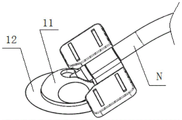
As shown in fig. 1, fig. 2 and fig. 3, in this embodiment, the skin surface indwelling device for guiding puncture according to the present invention includes: a support 11 made of PC material, an adhesive layer 12, a indwelling tube 13 made of polyurethane material, and sealing members 141 and 142. The support 11 is indirectly contacted with the skin surface through the adhesive layer 12 adhered to the bottom surface of the support, so that the support provides stable support for the whole skin surface indwelling instrument; an indwelling tube 13 is connected to the abutment 11, and the indwelling tube 13 has a passage P extending substantially along the length of the indwelling tube 13 for guiding a puncture needle (not shown) which, in the present embodiment, has a diameter slightly larger than the outer diameter of the puncture needle in order to provide a low frictional resistance to the puncture needle when passing through the passage in the indwelling tube. As can be seen from fig. 3, the indwelling tube body 13 has a proximal end located above the skin surface S in the indwelling occupying state and a distal end located below the skin surface S, and in order for the indwelling tube body 3 not to generate pressure on the blood vessel wall in the indwelling occupying state, the distal end of the indwelling tube body 3 in this embodiment is set to have an extension length such that the distal end thereof is close to the punctured blood vessel wall without contacting the punctured blood vessel wall. Seals 141 and 142 are provided in the passage P to seal the passage P.
Fig. 4 shows a concrete structure of the indwelling tube in the first embodiment.
As shown in fig. 4, the indwelling tube comprises a cylindrical tube body 132 and a spherical head 131 protruding radially from the tube body 132, which can be fittingly received in the spherical cavity of the holder 11, so that the angle at which the indwelling tube enters the subject can be varied. In addition, a first sealing member 141 provided at the distal end of the indwelling tube and a second sealing member 142 provided at the proximal end of the indwelling tube are provided in the passageway P of the indwelling tube, wherein the first sealing member 141 prevents the entry of blood or body fluid of a subject into the passageway P of the indwelling tube, and the second sealing member 142 prevents the entry of external contaminants into the passageway P of the indwelling tube. Of course, a seal may be provided in other embodiments. Preferably, the first and second sealing members 141 and 142 are self-sealing members, which can be self-sealed after the puncture object passes through, so that they can be repeatedly used without being replaced after each puncture. The self-sealing member may be made of silicone, butyl rubber, or other self-sealing material. In this embodiment, the first seal 141 is a thin self-sealing film and the second seal 142 is a self-sealing plug that is slightly thicker than the first seal, but in other embodiments, the two may be reversed, i.e., the first seal 141 is a slightly thicker self-sealing plug, the second seal 142 is a thin self-sealing film, or both may be substantially equally thick self-sealing films.
In other embodiments, a first seal provided at the distal end of the indwelling tube may be provided at the distal tip of the indwelling tube and formed as part of the indwelling tube, which allows the puncture needle to pass through the first seal and into the subcutaneous space without allowing body fluid or blood to pass through the first seal from the subcutaneous space into the passageway of the indwelling tube. For example, fig. 6 and 7 show two different configurations of such a seal, respectively.
Figure 5 shows an indwelling tube having a nipple valve structure 143. As shown in FIG. 5, the nipple valve structure 143 has a hole at its end, which may be a circular hole, a Y-shaped hole, a cross-shaped hole, a rice-shaped hole, or other similar structure. During operation, the puncture needle can enter the lower part of the skin surface through the hole, and on the contrary, the body fluid or blood of the object can not enter the channel of the indwelling tube body from the lower part of the skin surface through the hole.
Figure 6 shows an indwelling tube having a duckbill valve structure 144. As shown in figure 6, the duckbill valve structure 144 is shaped like a duckbill, having a linear opening at its end through which the needle can enter under the skin surface during operation, whereas body fluid or blood of the subject cannot enter the channel of the indwelling tube from under the skin surface through the linear opening.
Fig. 7 shows in cross section the specific structure of the abutment of the skin surface indwelling device for guiding puncture according to the first embodiment of the present invention.
As shown in fig. 7, the inside of the holder 1 has a first cavity 111 that matingly receives the tube body 132 shown in fig. 5 and a second cavity 112 that matingly receives the spherical head 131 shown in fig. 5.
Fig. 8 shows a top view of the mount shown in fig. 7. As shown in fig. 8, in the present embodiment, the support 11 further has a U-shaped opening 113 allowing the spherical head 131 of the indwelling catheter to enter the second cavity 112, the U-shaped opening 113 being elastic and having an aperture slightly smaller than the outer diameter of the spherical head 131. When the distal end of the indwelling tube enters the subject at a certain needle insertion angle, force is applied to the abutment 11 to slide the spherical head 131 into the second cavity 112 of the abutment 11, thereby quickly completing the connection between the abutment 11 and the proximal end of the indwelling tube 13. In addition, as can be seen from fig. 8, in the present embodiment, the support 11 further has a recess 114 for facilitating the holding of fingers.
In this embodiment, the spherical head 131 and the second cavity 112 are in interference fit to ensure that the seat 11 can not rotate relatively after being pressed and buckled on the indwelling tube 13.
In other embodiments, the spherical head and the second lumen may be otherwise secured against relative rotation after the abutment is coupled to the proximal end of the indwelling catheter.
For example, FIG. 9 shows a mount in another embodiment. As can be seen from fig. 9, the structure of the support is substantially the same as that of the first embodiment, except that the inner surface of the second cavity of the support in this embodiment has a raised pattern 115, and the raised pattern 115 can increase the friction between the second cavity and the spherical head of the indwelling tube, thereby ensuring that the support does not rotate relatively with respect to the indwelling tube after being pressed and buckled on the indwelling tube.
For another example, fig. 10 shows an indwelling tube body in yet another embodiment. As can be seen from fig. 10, the structure of the indwelling tube body is substantially the same as that of the indwelling tube body in the first embodiment, except that the external surface of the spherical head of the indwelling tube body in this embodiment has a raised pattern 133, and the raised pattern 133 can increase the friction force between the second cavity and the spherical head of the indwelling tube body, so as to ensure that the support is not rotated relatively after being pressed and buckled on the indwelling tube body.
In another embodiment, the inner surface of the second cavity of the seat and the outer surface of the spherical head of the indwelling tube may both have raised lines.
The raised lines may be spiral lines, toothed lines or other raised lines with shapes that increase friction.
In the first embodiment, the support 11 is detachably and fixedly connected with the indwelling catheter body 13. With the indwelling tube shown in fig. 4 and the support shown in fig. 7, during the operation, the indwelling tube 13 can enter the subject at an insertion angle selected according to the operation habit of the operator or different requirements of the patient, and after the distal end of the indwelling tube 13 enters the subject, the support 11 is connected with the proximal end of the indwelling tube 13, so as to fix the included angle between the bottom surface of the support 11 and the axis of the indwelling tube 13. The advantage of this connection is that the angle between the axis of the indwelling tube 13 and the bottom surface of the abutment 11 is made variable, so that the same specification of skin surface indwelling device can be used for different operators and patients. Generally, the angle between the bottom surface of the holder 11 and the axis of the indwelling tube 13 can be varied within the range of 20 to 40 degrees.
In addition, although the bottom surface of the support is not directly shown in the above drawings, it is preferable that the bottom surface of the support 11 in the first embodiment is provided with a plurality of protrusions protruding from the bottom surface. These bulges can improve the fixed effect of base on the one hand, and on the other hand can also make and have certain clearance between bottom surface and the skin to improve the gas permeability of skin, reduce the allergic risk of skin. The protrusions may be arranged in a pyramid shape or in a hemispherical shape.
In the first embodiment, the support 11 is fixed on the surface of the object skin through the adhesive layer 2. Fig. 11 shows the adhesive layer 2 used in the first embodiment, and as can be seen from fig. 11, the adhesive layer 2 is a U-shaped adhesive layer.
Fig. 12 shows a state where the holder 11 is fixed to the leather watch by the adhesive layer 2. As shown in fig. 12, the bottom surface of the holder 11 is bonded to the upper surface of the adhesive layer 2, and the lower surface of the adhesive layer 2 is bonded to the skin of the subject.
FIG. 13 shows an alternative embodiment of the adhesive layer. As shown in fig. 13, the adhesive layer is a U-shaped adhesive tape with release paper, the release paper of the adhesive layer has a cut 121, when the support is fixed, any end of the U-shaped release paper can be removed first when the release paper is removed, and then the release paper is removed from the back adhesive clockwise or counterclockwise.
In addition, in this embodiment, the inner and/or outer surface of the indwelling tube is coated with an antimicrobial coating to reduce the risk of infection when implanted subcutaneously. In other embodiments, the antimicrobial coating may be applied only to the inner and/or outer surface of the distal end of the indwelling tube for material savings. The antimicrobial coating may be a silver ion coating or a sulfadiazine coating, or other antimicrobial coatings known to those skilled in the art.
Preferably, a layer of antibacterial waterproof breathable film can be covered on the skin surface indwelling device during the period of the skin surface indwelling device staying on the guest skin surface, so that the antibacterial and antibacterial effects are further improved. In addition, the antibacterial waterproof breathable film also plays a role in further fixing a skin surface indwelling instrument.
In addition, as can be seen in figures 3, 4 and 10, in one and other embodiments, the distal end of the indwelling tube and adjacent to the distal end has a wedge portion with an outer diameter that tapers towards the distal end. As can be seen in figure 5, in this embodiment, the distal end and the proximal end of the indwelling tube body have arcuate portions which taper in outside diameter towards the distal end. The structure can reduce the resistance of the indwelling tube body in the process of entering the object, so that the indwelling tube body can enter the object more easily.
In this embodiment, the wall thickness of the indwelling tube body may be set to 0.1-1mm, for example 0.4 mm.
The use method of the skin surface indwelling device for guiding puncture comprises the following steps:
(1) at the beginning of the first treatment, the puncture needle N is passed through the passage of the indwelling tube 11, as shown in FIG. 14, at which time the indwelling tube 11 is fitted over the puncture needle; then, the puncture needle N is inserted into the subject through the skin surface S with the indwelling tube 11, as shown in fig. 15, as can be seen from fig. 15, in this state, the puncture needle enters the blood vessel V, the distal end of the indwelling tube 11 is located below the skin surface S, the distal end is close to the blood vessel V but does not contact the blood vessel wall of the blood vessel V, and the proximal end of the indwelling tube 11 is located above the skin surface S; then, as shown in FIG. 16, the abutment 13 is attached to the proximal end of the indwelling tube 11, and the abutment 13 is fixed to the skin surface by the adhesive layer 12 so that the angle between the bottom surface of the abutment 11 and the axis of the indwelling tube 13 is maintained, and the first treatment is performed in this state;
(2) after the first treatment is finished, the puncture needle is pulled out of the object, due to the limiting effect of the support 11, the skin surface indwelling device is indwelling in the skin surface to place the far end of the indwelling tube body in the object to help to form a puncture tunnel, in this state, the first sealing element in the channel can prevent blood or body fluid of the object from entering the indwelling tube body, and the second sealing element in the channel can prevent external pollutants from entering the indwelling tube body, as shown in fig. 17; then, covering a layer of bacterium-blocking waterproof breathable film on the skin surface indwelling instrument; then the patient can take the skin surface indwelling instrument home to have a rest;
(3) when the next treatment is started, the bacterium-blocking waterproof breathable film is firstly uncovered, and then the puncture needle can directly penetrate through a channel in the indwelling tube body to enter the object after conventional disinfection so as to perform the treatment;
and (4) repeating the step (3) until the treatment is finished.
The indwelling tube in step (3) may be an indwelling tube of an old skin surface indwelling device which is indwelling in the skin surface after the previous treatment is completed, or may be an indwelling tube of a skin surface indwelling device which is newly replaced after the previous skin surface indwelling device is removed at the start of the current treatment. That is, the skin surface indwelling device in the first embodiment can be repeatedly used in a plurality of treatments, and does not need to be replaced by a new one every treatment. The skin surface indwelling device in the first embodiment can be indwelling for 3-5 days on the skin surface, or can be replaced after 3-5 treatments. Of course, the time for the same skin surface indwelling device to be placed on the skin surface or the number of treatments to be applied can be appropriately reduced or increased according to the biocompatibility of the skin surface indwelling device.
In addition, it should be noted that, during the first treatment, the puncture needle may be a generally sharper puncture needle or a relatively blunt puncture needle, which is used during each treatment, and a relatively sharp puncture tunnel may be created by using the blunt puncture needle for the first treatment.
EXAMPLE III
FIG. 21 is a side view of a third embodiment of the skin surface indwelling device for guiding puncture according to the present invention.
Fig. 22 is a top view of the skin surface indwelling device for guiding puncture according to the third embodiment of the present invention.
FIG. 23 is a side sectional view of a third embodiment of the skin surface indwelling device for guiding puncture according to the present invention.
As shown in fig. 21, 22 and 23, in the present embodiment, the skin surface indwelling device for guiding puncture includes a holder 31 made of PC material, an indwelling tube 33 fixedly disposed in the holder 31, and a seal pin 44. Wherein the support has an opening 311, the sealing pin 44 is inserted into the indwelling tube 33 through the opening 311, and the tail end of the sealing pin protrudes from the distal end of the indwelling tube 33. As can be seen in figure 23, the opening 311 is tapered with a decreasing outside-to-inside diameter in order to facilitate guidance of the needle (not shown) into the channel.
Unlike the first and second embodiments, the seal in this embodiment is a seal pin 44. Fig. 24 shows the structure of the seal pin in the present embodiment. As shown in fig. 24, the seal pin 44 includes a pin 441 and a connecting member connected to a head end of the pin 441. The pin 441 is coaxially disposed within the indwelling tube 33, and the tail end of the pin 441 extends out of the distal end of the indwelling tube 33. Based on the structure, after the skin surface indwelling instrument is indwelling in the skin surface, the part of the pin extending out of the distal end of the indwelling tube body 33 also plays a role in occupying space, and in addition, the pin arranged in the indwelling tube body 33 can also play a role in enhancing the strength of the wall of the indwelling tube body. In addition, in the present embodiment, in order not to increase the pressure of the blood vessel wall, the tail end of the pin 441 is also set to be close to the punctured blood vessel wall without contacting the punctured blood vessel wall, and since the tail end of the pin 441 is extended out of the distal end of the indwelling tube 33, the distal end of the indwelling tube 33 is also close to the punctured blood vessel wall without contacting the punctured blood vessel wall, but the tail end of the pin 441 is closer to the blood vessel wall than the distal end of the indwelling tube. In addition, as can be seen in fig. 24, in this embodiment, the end of the pin 441 is curved to reduce the resistance of the pin along with the indwelling catheter body during entry into the subject. In this embodiment, the connecting member is provided in a structure that can be quickly coupled to and detached from the cradle, and specifically, the connecting member includes a U-shaped beam 442 fixedly coupled to the head end of the pin 441, and first claws 443 respectively provided at the distal ends of both arms of the U-shaped beam 442.
FIG. 25 shows the structures of the holder and the indwelling tube in the third embodiment of the skin surface indwelling device for guiding puncture according to the present invention. As can be seen in fig. 25, the seat 31 has a cavity therein for accommodating the indwelling catheter 33, the indwelling catheter 33 being fixedly disposed within the cavity. As can be seen in fig. 23, the cavity has a step 312, and when the indwelling tube 33 extends into the cavity, further extension of the indwelling tube 33 is stopped by the step 312, thereby facilitating quick positioning of the indwelling tube 33 relative to the abutment 31. With continued reference to fig. 25, it can be seen that the support 33 has a raised step with a catch 313 on either side of the step, the catch 313 being adapted to engage with the first catch 443 to enable quick connection and disconnection of the support 31 to the seal pin 44. Specifically, when the seal pin 44 needs to be quickly connected to the support 31, the two arms of the U-shaped beam 442 are pressed toward each other, so as to bring the pair of first claws 443 toward each other, then the first claws 443 are inserted into the slots 313, and then the pressing force is released, at this time, the two arms of the U-shaped beam 442 and the first claws 443 are reset under the elastic action, and the first claws 443 are clamped in the slots, so that the quick connection of the seal pin 44 to the support 31 is completed. When it is desired to remove the seal pin 44 from the support 31, the two arms of the U-shaped beam 442 are pressed towards each other again, thereby bringing the pair of first pawls 443 towards each other, and then the first pawls 443 are disengaged from the notches 313, thereby completing the quick removal of the seal pin 44 from the support 31. As can be seen from fig. 25, the support 31 is further provided with a fabrication hole 314 for injection molding of the locking groove 313.
In addition, as can be seen from fig. 23 and 24, in the present embodiment, the pin 441 is of a constant diameter in the axial direction, and the pin 441 is always in close contact with the indwelling tube body 33. The pin 441 is always tightly attached to the retaining tube 33, so that the present embodiment has a better sealing effect. In addition, because the pin 441 is always tightly attached to the indwelling tube 33, the pin 441 can provide stronger supporting force for the wall of the indwelling tube 33.
Figures 26 and 27 show a seal pin and its relationship to an indwelling tube in another embodiment. The seal pin of fig. 26 and 27 differs from the seal pin of fig. 23 and 24 in that in the embodiment of fig. 26 and 27 the pin shank of the seal pin is not of constant diameter in its axial direction but comprises at least two portions of different outer diameter, wherein the outer diameter of the trailing portion 4411 is greater than the outer diameter of the main portion 4412. As can be seen in figure 27, the trailing end portion 4411 of the pin is in close contact with the retention tube 33 to ensure a seal that does not allow blood or body fluids from the subject to enter the retention tube. And the outer diameter of the main body portion 4412 of the pin is slightly smaller than the inner diameter of the indwelling tube 33 so that a certain clearance is provided between the main body portion 4412 of the pin and the indwelling tube 33, which can reduce the frictional force of the pin when entering and exiting the indwelling tube, compared to the structure shown in fig. 23 and 24, thereby making it easier to enter and exit the indwelling tube.
Preferably, the present embodiment may further comprise an auxiliary member in order to more easily remove the skin surface indwelling device when necessary. The auxiliary member can be connected with the support base shown in figures 21-23 and 25 in a matching way, and also can be connected with the support base shown in figure 27 in a matching way. Fig. 28 schematically shows a specific structure of the auxiliary member. Fig. 29 shows the structure of the auxiliary element in a sectional view. As shown in fig. 28 and 29, the tail end of the auxiliary member 34 is provided with a second latch 341 cooperatively connected with the latch groove 313 on the support 31, and the connection and disconnection operation of the second latch 341 with the latch groove 313 is similar to the connection and disconnection operation of the latch groove 313 and the first latch 443 described above. The leading end of the accessory 34 is provided with a connection for connection to the needle, for example a radially inwardly projecting step 342 as shown in figure 29, which step 342 is adapted to engage a corresponding recess in the needle to effect connection of the needle to the accessory. Of course, in other embodiments, the connection portion may also adopt other implementation manners, such as a threaded connection, a snap connection, a pin connection, and the like. In addition, as can be seen in fig. 29, the auxiliary element 34 also has a groove 343 for receiving the puncture needle.
Fig. 30 and 31 show another way of realising the quick coupling and uncoupling of the coupling element of the sealing pin to the support. As can be seen in fig. 30, the connecting element fixedly attached to the head end of the pin also comprises a U-shaped beam 442, the ends of the two arms of the U-shaped beam 442 being provided with wedge-shaped guide posts 444, and in addition, the head end of the pin being provided with an O-ring 445. The bracket, which is adapted to the connector, is provided with a hole groove (not visible) matching the wedge-shaped guide post 444 as shown in fig. 31, and the bracket 31 is further provided with a fabrication hole 314 for injection molding the hole groove. When the pin is inserted into the indwelling pipe body to seal it, the wedge-shaped guide post 444 is inserted into the hole groove of the support 31 correspondingly, and at the same time, the O-ring 445 is disposed between the pin and the support, so that the relative position between the seal pin and the support can be fixed by increasing the frictional force between the pin and the support, thereby achieving the connection of the seal pin and the support. When the seal pin needs to be pulled out of the indwelling tube body, a pulling force greater than the frictional force needs to be applied to the seal pin.
Although the pins shown in fig. 30 have the same diameter, they may be configured as pins in fig. 26.
In the third embodiment, the pin can be a solid structure or a hollow structure. If the pin is provided as a solid structure, it can provide better supporting force for the tube wall of the indwelling tube body than a hollow structure. The hollow pin saves more material and has lighter self-weight.
In addition, in the third embodiment, it is preferable that the outer surface of the pin and the inner and outer surfaces of the indwelling tube body are coated with the antibacterial coating. The antimicrobial coating may be a silver ion coating or a sulfadiazine coating, or other antimicrobial coatings known to those skilled in the art.
In addition, although not explicitly shown in the drawings of the present embodiment, the bottom surface of the support 31 is preferably provided with a plurality of protrusions protruding from the bottom surface. Be equipped with the arch on the bottom surface, can improve fixed effect on the one hand, on the other hand can also make and have certain clearance between bottom surface and the skin table to improve the gas permeability of skin table, reduce the allergic risk of skin table.
Preferably, the skin surface indwelling device of the embodiment can be further covered with a bacteria-blocking waterproof breathable film, so that the antibacterial and bacteria-blocking effect is further improved, and in addition, the bacteria-blocking waterproof breathable film also plays a role in further fixing the skin surface indwelling device.
In addition, in other embodiments, the support may also have depressions thereon to facilitate finger gripping.
In addition, the inner diameter of the indwelling tube 33 in this embodiment is also preferably slightly larger than the outer diameter of the needle.
In the embodiment, the included angle between the bottom surface of the support 31 and the axis of the indwelling tube 33 of the skin surface indwelling instrument with different specifications can be set to be 20-40 degrees. However, the angle between the bottom surface of the seat 31 and the axis of the indwelling tube 33 is constant for the same skin surface indwelling device.
In this embodiment, when the seal pin is attached to the holder, the outer profile of the holder may be of a hemispherical type or dome type or mouse type, thereby facilitating gripping by an operator.
The use method of the skin surface indwelling device for guiding puncture comprises the following steps:
(1) when the first treatment is started, the puncture needle firstly punctures the object to carry out the first treatment;
(2) after the first treatment is finished, the puncture needle is pulled out of the object, and then the far end of the indwelling tube body and the sealing pin are gradually punctured into the object through the skin surface along the puncture path of the puncture needle until the bottom surface of the base is contacted with the skin surface; the skin surface indwelling device is placed on the skin surface, so that the far end of the indwelling tube body and the sealing pin are placed in a guest body together for occupying, and a puncture tunnel is formed; covering a bacterium-blocking waterproof breathable film on the skin surface indwelling instrument, and then enabling a patient to conveniently take the skin surface indwelling instrument to go home for rest;
(3) when the next treatment is started, the bacteria-resistant waterproof breathable film is firstly uncovered, the seal pin is pulled out of the indwelling tube body, and then the puncture needle N penetrates through a channel in the indwelling tube body to enter the object so as to carry out the next treatment, as shown in fig. 32;
(4) after the next treatment is finished, the skin surface indwelling device and the puncture needle are pulled out of the object, and then the far end of the indwelling tube body of a new skin surface indwelling device and the sealing pin are inserted into the object along the puncture tunnel immediately, so that the new skin surface indwelling device is indwelling in the skin surface;
and (4) repeating the steps (3) and (4) until the treatment is finished.
The treatment may be a hemodialysis treatment, or other treatment procedures, such as subcutaneous injections.
As can be seen from the above description, the use of the skin surface indwelling device is also disposable, that is, it is not desirable to reuse it. This is because the pin tail end of the seal pin is in contact with the subcutaneous tissue of the subject in the indwelling state, and the seal pin needs to be pulled out of the indwelling tube body in the subsequent operation process, which makes the seal pin easily contaminated by external contaminants. Therefore, in order to ensure the sterility of the device, it is recommended to replace a new skin indwelling device for each treatment.
When the skin surface indwelling device comprises the auxiliary member described above, the step (3) described above includes the steps of: at the start of the next treatment, the seal pin is first pulled out from the indwelling tube, the puncture needle N to which the auxiliary tool 34 is connected is inserted into the subject through the passage in the indwelling tube 33, and the auxiliary tool 34 is connected to the holder 31 after the puncture needle reaches a subcutaneous position, whereby the treatment is performed, as shown in fig. 33. The step (4) includes the steps of: after the next treatment is finished, an outward pulling force is exerted on the puncture needle N, the puncture needle N and the skin surface indwelling device are pulled out of the object together, and then the far end of the indwelling tube body of a new skin surface indwelling device and the sealing pin are immediately inserted into the object along the puncture tunnel, so that the new skin surface indwelling device is indwelling in the skin surface.