The present application claims priority and benefit from german utility application No. DE202018004979.4 filed on 25/10/2018, and U.S. provisional patent application No. 62/773,464 filed on 30/11/2018, the contents of which are incorporated herein by reference.
Disclosure of Invention
According to one aspect of the present disclosure, a heat exchanger is provided having a length and a width and comprising a plurality of flow sections separated by flow barriers. Each flow section has a first end and a second end spaced apart along the length of the heat exchanger. The flow segments are arranged side-by-side along the width of the heat exchanger, and adjacent pairs of the flow segments are in fluid communication with each other through the openings in the flow barrier. The plurality of flow sections includes an inlet flow section, an outlet flow section, and at least first and second intermediate flow sections between the inlet and outlet flow sections.
The heat exchanger further comprises: an inlet port in fluid communication with a first end of an inlet flow section; an outlet port in fluid communication with an outlet flow section; and a first bypass channel extending between the inlet port and the at least one intermediate flow section.
According to one aspect, the heat exchanger further comprises an even number of intermediate flow sections, such that the heat exchanger defines a plurality of U-shaped flow areas, and such that the outlet port is in fluid communication with the first end of the outlet flow section.
According to one aspect, the plurality of U-shaped flow areas includes a first U-shaped flow area and a second U-shaped flow area. The first U-shaped flow region includes an inlet flow section and a first intermediate flow section, wherein the first opening provides fluid communication between the second end of the inlet flow section and the first intermediate flow section. The second U-shaped flow area includes a second intermediate flow section and an outlet flow section, wherein the third opening provides fluid communication between the second end of the second intermediate flow section and the outlet flow section.
According to one aspect, the first bypass passage extends transversely from the inlet port to a first end of at least one of the first and second intermediate flow sections.
According to one aspect, the first bypass passage extends transversely from the inlet port to a second opening through which fluid communication is provided between the first end of the first intermediate flow section and the first end of the second intermediate flow passage.
According to one aspect, the heat exchanger further comprises a second bypass channel branching from the first U-shaped flow area and extending to the second U-shaped flow area.
According to one aspect, the second bypass channel has a first end in fluid communication with the inlet flow section between the first and second ends of the inlet flow section, and a second end in fluid communication with the outlet flow section between the first and second ends of the outlet flow section.
According to one aspect, a heat exchanger includes a first flat plate and a second formed plate having a peripheral flange, the second formed plate sealingly joined to the first plate along the peripheral flange. The heat exchanger having a pair of opposed longitudinally extending side edges and a pair of opposed transversely extending end edges; wherein the second bypass channel extends longitudinally along one of the side edges between the inlet flow section and the peripheral flange of the second plate; and wherein the second bypass channel also extends laterally along one end edge between the second end of the flow section and the peripheral flange of the second plate.
According to one aspect, the second end of the second bypass channel is located at the second end of the second intermediate flow section, the second end of the outlet flow section, and/or at a third opening between the second end of the second intermediate flow section and the outlet flow section.
According to one aspect, the second bypass channel also extends longitudinally along a second one of the side edges between the outlet flow section and the peripheral flange of the second plate.
According to one aspect, the second end of the second bypass channel is located between the first end and the second end of the outlet flow section.
According to one aspect, the second end of the second bypass channel is located at the first end of the outlet flow channel and/or near the outlet port.
According to one aspect, each flow section defines a heat transfer area, said heat transfer area being defined as an area of the flow section adapted to allow a heat transfer fluid to flow therethrough; wherein the inlet flow section has a smaller heat transfer area than the first intermediate flow section; and wherein the second intermediate flow section has a smaller heat transfer area than the outlet flow section.
According to one aspect, a heat exchanger includes a first flat plate and a second formed plate having a peripheral flange, the second formed plate being sealingly joined to the first plate along the peripheral flange; wherein the second plate comprises one or more protrusions in the inlet and second intermediate flow sections adapted to reduce the heat transfer area in each of the inlet and second intermediate flow sections relative to the respective first and outlet flow sections.
According to one aspect, the second plate comprises a first blocking projection and a second blocking projection, wherein the first blocking projection is located at the first end of the inlet flow section and the second blocking projection is located at the first end of the second intermediate flow section.
According to one aspect, each flow section comprises a plurality of channel ribs dividing each flow section into a plurality of longitudinally extending flow channels.
According to one aspect, the number and/or width of the channel ribs varies between the inlet flow section and the first intermediate flow section, and/or between the second intermediate flow section and the outlet flow section.
According to one aspect, the number of channel ribs in the inlet flow section is smaller than the number of channel ribs in the first intermediate flow section; and/or the number of channel ribs in the second intermediate flow section is smaller than the number of channel ribs in the outlet flow section.
According to one aspect, at least one of the channel ribs in the inlet flow section is wider than each of the channel ribs in the first intermediate flow section; and/or at least one of the channel ribs in the second intermediate flow section is wider than each of the channel ribs in the outlet flow section.
According to one aspect, a heat exchanger includes a first flat plate and a second formed plate having a peripheral flange along which the second formed plate is sealingly joined to the first plate, the heat exchanger having a pair of opposed longitudinally extending side edges and a pair of opposed laterally extending end edges. Each of the first and second U-shaped flow areas is adapted to underlie a row of battery cells in thermal contact with an outer surface of the first plate of the heat exchanger.
According to one aspect, the inlet and outlet ports are provided in the first plate and are located in a central region of the heat exchanger, outside the region of the first plate adapted to be in thermal contact with the battery cells.
According to one aspect, the inlet port and the outlet port are located along a transverse mirror plane bisecting the heat exchanger into a first portion and a second portion; and wherein the first portion and the second portion are mirror images of each other.
According to one aspect, the first end of each flow section is located in a central region of the heat exchanger and the second end of each flow section is located near one of the end edges.
Detailed Description
The heat exchanger described herein is generally a generally flat, planar fluid carrying plate having opposing exterior surfaces, at least one of which is adapted for thermal contact with one or more cells and/or battery modules of a rechargeable battery of a BEV or HEV.
In some embodiments, the heat exchanger described herein is particularly adapted for thermal contact with a plurality of battery cells arranged in two or more longitudinally extending rows.
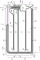
A heat exchanger 10 according to a first embodiment is shown in fig. 1 to 9. The heat exchanger 10 has a length along a longitudinal axis (y-axis) and a width along a transverse axis (x-axis). The heat exchanger 10 includes a first plate 12 having inner and outer surfaces 14, 16 and a second plate 18 having inner and outer surfaces 20, 22. The heat exchanger 10 is a "cold plate" in which the outer surface 16 of the first plate 12 provides a flat surface on which one or more battery cells 2 and/or battery modules 4 are supported.
Fig. 1 shows a battery module 4 comprising seventy-two prismatic battery cells 2 supported on an outer surface 16 of a first plate 12. The cells 2 are arranged in two longitudinally extending rows (along the y-axis) of thirty-six cells, the two rows being arranged side-by-side. Each row of thirty-six cells includes two groups of eighteen cells, the two groups of cells 2 in each row being longitudinally spaced from each other, as discussed further below.
Each cell 2 has a plurality of rectangular surfaces including a top surface 54, a bottom surface 56, a pair of opposing side surfaces 58 and a pair of opposing end surfaces 60. The bottom surface 56 is in thermal contact with the outer surface 16 of the first plate 12. Although not shown, the battery cells 2 are electrically connected together, and the battery module 4 is electrically connected to other battery modules of the vehicle battery. It should be understood that the total number of battery cells 2 may be different from that shown in the drawings, and that the battery cells 2 may be arranged in more than two longitudinal rows.
A thin layer of Thermal Interface Material (TIM) (not shown) may be provided between the outer surface 16 of the first plate 12 and the bottom surface 56 of the battery cell 2 to enhance thermal contact between the heat exchanger 10 and the battery cell 2. The TIM may comprise a thermally conductive grease, wax, or metallic material.
The heat exchanger 10 is generally rectangular, elongated along a longitudinal axis, having a pair of longitudinally extending first and second side edges 25, 26 and a pair of transversely extending first and second end edges 44, 46, wherein the side edges 25, 26 and the end edges 44, 46 are also referred to herein as side and end edges of the first and second plates 12, 18.
The second plate 18 has opposed inner and outer surfaces 20, 22 and is formed, for example by stamping, drawing or moulding, to provide a plurality of projections which together define a central region 24, the central region 24 having a plurality of grooves or channels surrounded on all sides by a planar flange 28, the planar flange 28 defining a planar peripheral sealing surface 30 on the inner surface 20 of the second plate 18. The first and second panels 12, 18 are sealingly joined together with their inner surfaces 14, 20 in opposed facing relationship to one another, and wherein portions of the inner surfaces 14, 20 are spaced apart from one another. The planar peripheral sealing surface 30 of the second plate 18 is sealingly joined to the planar peripheral sealing surface 32 on the inner surface 14 of the first plate 12, with portions of the inner surfaces 14, 20 that are interior to the respective sealing surfaces 32, 30 being spaced from one another.
The heat exchanger 10 further includes a first port 40 and a second port 42, the first port 40 and the second port 42 including apertures in the first plate 12 located within the planar peripheral sealing surface 32 through which heat transfer fluid is introduced into the heat exchanger 10 and discharged from the heat exchanger 10. The first port 40 is provided with a first tubular fitting 48 and the second port 42 is provided with a second tubular fitting 50, the fittings 48, 50 projecting upwardly from the outer surface 16 of the first plate 12 to provide fluid communication between the fluid flow passageway 34 and a fluid circulation system (not shown) of the vehicle. In the present embodiment, the first port 40 and the first fitting 48 are inlet ports and fittings, while the second port 42 and the second fitting 50 are outlet ports and fittings.
The ports 40, 42 and fittings 48, 50 are located in a central region 62 of the heat exchanger 10, the central region 62 being outside the area occupied by the battery cells 2. The central region 62 divides each row of thirty-six cells into two groups of eighteen cells. Although in the present embodiment, the ports 40, 42 and fittings 48, 50 are located in the central region 62, the ports 40, 42 and fittings may alternatively be located along one of the end edges 44, 46 of the heat exchanger 10.
The plates 12, 18 and fittings 48, 50 may be constructed of aluminum or alloys thereof and may be joined together by brazing in a brazing furnace. Although the first plate 12 and the second plate 18 are shown as having the same or similar thickness, the first plate 12 may include a heat sink or heat spreader having a thickness that is greater than the thickness of the second plate 18 over at least a portion of its area.
At least some of the channels or grooves in the central region 24 of the second plate 18 define the bottom and sides of the plurality of fluid flow channels of the heat exchanger 10. As can be seen from the figures, the ports 40, 42 are positioned along a transverse mirror plane P that bisects the heat exchanger 10 into a first portion 64 and a second portion 66, wherein the patterns of channels or grooves in the first portion 64 and the second portion 66 are mirror images of each other.
The following is a description of the pattern of channels or grooves in the first portion 64, and the description applies equally to the second portion 66.
Fig. 4A and 4B are top plan views showing a portion of the second plate 18 in the first portion 64 of the heat exchanger 10, with the first (inlet) port 40 and the second (outlet) port 42 positioned to overlie the second plate 18. As shown in fig. 7, an overall W-shaped flow pattern is defined in the first portion 64, which includes four longitudinally extending legs. Alternatively, as can be seen from fig. 7, the entire flow pattern can be seen as a pair of U-shaped flow patterns, each U-shaped flow pattern being located underneath a row of battery cells 2, the outline of which can be seen in fig. 7.
Fig. 4B illustrates several features of the second plate 18 separately, which will now be described below, while eliminating several other features of the second plate 18.
As shown in fig. 4B, the first portion 64 of the heat exchanger 10 defines a plurality of flow sections 68, 70, 72, 74 arranged side-by-side along the width of the heat exchanger 10. Each of the flow segments 68, 70, 72, 74 has a first end and a second end spaced apart along the longitudinal axis, wherein the first end of each flow segment is located at the central region 62 of the heat exchanger 10 and the second end of each flow segment is located proximate one of the end edges 44, 46 of the heat exchanger 10.
Each flow section 68, 70, 72, 74 includes one of the longitudinal legs of the W-shaped flow pattern shown in fig. 7, wherein adjacent flow sections 68, 70, 72, 74 are separated by a flow barrier. In this regard, adjacent flow sections 68, 70 are separated by a first flow barrier 76; adjacent flow segments 70, 72 are separated by a second flow barrier 78; adjacent flow segments 72, 74 are separated by a third flow barrier 80.
Each flow barrier 76, 78, 80 includes an opening through which fluid communication is provided between adjacent pairs of flow sections 68, 70, 72, 74. In this regard, the first flow barrier 76 has a first opening 82 that provides fluid communication between the second end of the first flow section 68 and the second flow section 70; the second flow barrier 78 has a second opening 84 providing fluid communication between the first end of the second flow section 70 and the first end of the third flow section 72; the third flow barrier 80 has a third opening 86 providing fluid communication between the second end of the third flow section 72 and the second end of the fourth flow section 74. As can be seen, the openings 82, 84, 86 of successive flow barriers 76, 78, 80 are located at opposite ends of the flow sections 68, 70, 72, 74, providing a W-shaped flow pattern between the first port 40 and the second port 42.
The first (inlet) port 40 is located at a first end of the first flow section 68, which is also referred to herein as the "inlet flow section". The second (outlet) port 42 is located at a first end of the fourth flow section 74, which is also referred to herein as the "outlet flow section". The second and third flow segments 70, 72 are located between the inlet and outlet flow segments 68, 74 and are each referred to herein as an "intermediate flow segment". It will be appreciated that the number of intermediate flow sections may be greater than two, for example in embodiments where more than two rows of cells 2 are in thermal contact with the first plate 12. Also, for example, where the plurality of flow sections is odd, the second port 42 may be located at the second end of the outlet flow section (in both portions 64, 66).
In the present embodiment, the first row of cells 2 is located above and in thermal contact with the first flow section 68 and the second flow section 70, the two flow sections 68, 70 forming a first U-shaped flow area 88 (fig. 4A) below the first row of cells 2. Similarly, the second row of cells 2 is located above and in thermal contact with the third flow section 72 and the fourth flow section 74, the two flow sections 68, 70 forming a second U-shaped flow area 90 below the second row of cells 2. The two U-shaped flow areas 88, 90 are arranged in series and separated by the second barrier 78, wherein the first U-shaped flow area formed by the flow sections 68, 70 supplies the heat transfer fluid to the second U-shaped flow area formed by the flow sections 72, 74, i.e. through the second opening 84 of the second barrier 78.
As the heat transfer fluid flows through the first flow section 68 and the second flow section 70 including the first U-shaped flow area 88, the heat transfer fluid absorbs heat from the first row of battery cells 2, and as the heat transfer fluid flows between the first port 40 and the second opening 84 of the second flow barrier 78, the temperature of the heat transfer fluid increases. Thus, the temperature of the heat transfer fluid received through the second opening 84 into the second U-shaped flow region 90 is higher than the temperature of the heat transfer fluid supplied through the first (inlet) port 40 to the first U-shaped flow region 88. Such a temperature difference between the heat transfer fluid flowing through the first U-shaped flow area 88 and the second U-shaped flow area 90 may result in a temperature difference between the battery cells 2 in the first row and the second row.
The present embodiment provides a feature of minimizing a temperature difference between the heat transfer fluids flowing through the first and second U-shaped flow regions 88 and 90, thereby improving temperature uniformity of the battery cells 2 in the first and second rows. These features will now be described below.
The first and second portions 64, 66 of the heat exchanger 10 each include a first bypass passage 92 that allows a portion of the heat transfer fluid entering the heat exchanger 10 through the first port 40 to partially or completely bypass the first U-shaped flow area 88, flowing directly from the first port 40 to the second U-shaped flow area 90. The direction of the split between the first bypass passage 92 and the first flow section 68 is shown by the arrows in fig. 8. These arrows only show the direction of flow, not the precise location of the flow channel through which the fluid flows. In this regard, the lateral arrows of fig. 8 only indicate the direction of fluid flow through the first bypass passage 92, and are displaced from the first bypass passage 92 along the y-axis. The relatively cool heat transfer fluid entering the second U-shaped flow area 90 through the first bypass passage 92 mixes with the hotter heat transfer fluid entering the second U-shaped flow area 90 through the second opening 84, thereby reducing the temperature of the total amount of heat transfer fluid entering the second U-shaped flow area 90. This has the effect of reducing the temperature difference between the heat transfer fluid flowing through the first U-shaped flow region 88 and the second U-shaped flow region 90, thereby improving the temperature uniformity of the battery cells 2 in the first and second rows.
In the present embodiment, the first bypass channel 92 extends transversely from the area of the first port 40 directly to a first end of one of the intermediate flow sections 70, 72, in particular the first end of the third flow section 72. However, it should be understood that the first bypass passage 92 may alternatively deliver cold heat transfer fluid directly into the first end of the second flow section 70, and/or directly into the second opening 84 between the second flow section 70 and the third flow section 72. It will be appreciated that the amount of heat transfer fluid transferred through the first bypass passage 92 will be determined by the width of the bypass passage 92 relative to the width of the passage through which the heat transfer fluid from the first port 40 enters the first end of the first flow section 68.
As also shown in FIG. 4B, the present embodiment also includes a second bypass channel 94 that branches from the first U-shaped flow region 88 and diverts a portion of the heat transfer fluid to the second U-shaped flow region 90. In the present embodiment, the second bypass passage 94 is relatively narrow compared to the width of the flow sections 68, 70, 72, 74, and has a first end 96 and a second end 98. The first end 96 is positioned along an outer edge of the first flow section 68, proximate the planar flange 28, and between the first and second ends of the first flow section 68 such that the second bypass channel 94 receives heat transfer fluid from the first port 40 and/or the first flow section 68. The second bypass channel 94 extends from the first end 96 along an outer edge of the second plate 18, adjacent the planar flange 28, along the side edge 25, along the end edge 44, and along the side edge 26. The second end 98 of the second bypass channel 94 is positioned along an outer edge of the fourth flow section 74 such that the second bypass channel 94 delivers the heat transfer fluid to the fourth flow section 74. In the present embodiment, the second end 98 is located at the first end of the fourth flow section 74, proximate the second port 42. The second bypass channel 94 is defined between the planar flange 28 and a circumferential rib 95, the circumferential rib 95 extending from a first end 96 to a second end 98 of the second bypass channel 94 and being substantially parallel to the planar flange 28 along the side edge 25, the end edge 44, and the side edge 26. In the present embodiment, the portion of the peripheral rib 95 extending along the side edge 25 is thicker than the other portions of the peripheral rib 95 for reasons that will be explained below. It can be seen that the second flow barrier 78 is joined to a portion of the peripheral rib 95 that extends along the end edge 44. The circumferential rib 95 is shown in the drawings as being continuous, however, it may include one or more gaps to allow fluid communication with one or more of the flow sections 68, 70, 72, 74 if desired. For example, fig. 4B shows a gap 97 in phantom to allow communication between the second bypass passage 94 and the flow section 74.
It can be seen that the second bypass channel 94 is adapted to carry a relatively cool heat transfer fluid around the periphery of the second plate 18 and around the periphery of the first and second U-shaped flow areas 88, 90. This will also help to reduce the temperature difference between the first U-shaped flow area 88 and the second U-shaped flow area 90, thereby improving the temperature uniformity of the battery cells 2 in the first row and the second row. In embodiments in which the peripheral rib 95 is continuous, the heat transfer fluid flowing through the second bypass channel 94 may not mix with the heat transfer fluid in the second U-shaped flow region 90 until it is proximate to the second port 42, and depending on the location of the second end 98, the fluid in the second bypass channel 94 may be slightly heated by thermal conduction through the first and second plates 12, 18.
It should be appreciated that the first end 96 of the second bypass channel 94 may be located at any point along the outer edge of the first flow section 68 between the first and second ends thereof, and the second end 98 of the second bypass channel 94 may similarly be located at any point along the outer edge of the fourth flow section 74 between the first and second ends thereof. For example, in some embodiments, the first end 96 of the second bypass passage 94 may be located proximate to the first port 40, while the second end 98 of the second bypass passage 94 may be located proximate to the second port 42.
The bottom and sides of the flow sections 68, 70, 72, 74 and bypass channels 92, 94 include grooves or channels formed in the central region 24 of the second plate 18, which are defined by a plurality of projections as shown in fig. 4B. The projections shown in fig. 4B all have a top sealing surface, which may be flat (see fig. 6) or rounded and coplanar with the planar flange 28, such that the sealing surface of the projections is sealingly joined to the inner surface 14 of the first panel 12 in the same manner as the sealing surface 30 defined by the planar flange 28.
As noted above, fig. 4B shows only some of the features of the second plate 18, while fig. 4A shows that the second plate 18 includes additional projections that define support elements and/or flow enhancement features. These additional features will now be described below.
Fig. 4A shows that the second plate 18 includes a plurality of protrusions in the form of elongated support ribs or circular dimples, which are designated by reference numeral 100 and are referred to herein as "support elements". The support elements 100 strengthen the area of the heat exchanger 10 where no other protrusions provide structural support for the first and second plates 12, 18, such as at the first and second ends of one or more of the flow sections 68, 70, 72, 74, providing manifold spaces in which heat transfer fluid may be distributed laterally across the width of the flow sections 68, 70, 72, 74. The support element 100 may also be disposed in or near the first, second, and third openings 82, 84, 86 of the flow barriers 76, 78, 80. It should be understood that the support element 100 may also provide flow enhancement, such as increasing turbulence and/or breaking boundary layers.
In addition to the support elements 100, fig. 4A also shows that the second plate 18 includes a plurality of projections that divide each flow section 68, 70, 72, 74 into a plurality of separate flow channels. These projections are indicated by reference numeral 102 and are referred to herein as "channel ribs" and the flow channels between the channel ribs 102 are indicated by reference numeral 104. The channel ribs 102 extend at least substantially longitudinally between the first and second ends of the flow sections 68, 70, 72, 74.
As can be seen in fig. 4A, the number and width of the channel ribs 102 may vary between the various flow sections 68, 70, 72, 74, and may also vary slightly within at least some of the flow sections 68, 70, 72, 74. This has the effect of varying the width and number of flow channels 104 in the flow sections 68, 70, 72, 74. Further, the heat exchanger 10 may include one or more flow obstruction projections, as described below, to vary the heat transfer area of the flow sections 68, 70, 72, 74, wherein the heat transfer area of each flow section 68, 70 is defined as the area of that flow section through which the heat transfer fluid flows.
The primary reason for varying the number and width of the flow channels 104, and/or varying the heat transfer area of the flow sections 68, 70, 72, 74, is to provide improved temperature uniformity between the flow sections making up each of the U-shaped flow areas 88, 90, i.e., between the first flow section 68 and the second flow section 70 making up the first U-shaped flow area 88; and provides improved temperature uniformity between the third flow section 72 and the fourth flow section 74 that make up the second U-shaped flow region 90.
This variation in the number and width of the channels and/or heat transfer areas in the U-shaped flow region is described in detail in commonly assigned U.S. provisional patent application No. 62/682,610, filed ON 8.6.2018, entitled "heat transfer medium for improving heat transfer (utizotion of DEAD CHANNEL TO improved heat transfer efficiency ON THERMAL INTERFACE MATERIAL"), the entire contents of which are incorporated herein by reference.
In the first U-shaped flow region 88 of the heat exchanger 10, it can be seen that the first flow section 68 includes two channel ribs 102, such that the first flow section 68 includes three flow channels 104 (not including the second bypass channel 94), which may have similar widths along part or all of their lengths. One channel rib 102 in the first flow section 68 is relatively wider than the other channel rib 102. Furthermore, the greater width of the circumferential rib 95 along the side edge 25, and/or the greater width of the flange 28 along the side edge 25 in the region between the inlet port 40 and the first end 96 of the second bypass channel 94, results in some additional reduction in heat transfer area in the first flow section 68.
The second flow section 70 of the first U-shaped flow region 88 has a more regular rib pattern formed by two straight elongated channel ribs 102, such that the second flow section 70 includes three straight longitudinal flow channels 104, which may have similar or substantially the same width.
In addition, a major portion of the first end of the first flow section 68 proximate the first port 40 is occupied by a first flow blocking projection 106, the first flow blocking projection 106 forming part of the first flow barrier 76 and including a laterally extending rib 106a partially defining the first bypass channel 92. The relatively wide channel ribs 102 and first flow obstruction projections 106 together provide the first flow section 68 with a smaller heat transfer area than the second flow section 70, and the inventors have found that this reduction in the heat transfer surface area of the first flow section 68 relative to the second flow section 70 can improve temperature uniformity between the first and second flow sections 68, 70, thereby improving temperature uniformity of the cells 2 within the first row of cells 2 in thermal contact with the first U-shaped flow region 88.
In the second U-shaped flow region 90 of the heat exchanger 10, it can be seen that the third flow section 72 includes three channel ribs 102, such that the third flow section 72 includes four flow channels 104, which may have similar widths along some or all of their lengths. Two channel ribs 102 in the third flow section 68 are relatively wider than the other channel rib 102.
The fourth flow section 74 of the second U-shaped flow region 90 has a more regular rib pattern than the third section 72 formed by three straight elongated channel ribs 102 (excluding the projections separating the flow section 74 from the second bypass channel 94) such that the second flow section 70 includes four straight longitudinal flow channels 104 of similar or substantially the same width.
In addition, a major portion of the first end of the third flow section 72 proximate the second opening 84 and the first bypass channel 92 is occupied by a second flow obstruction projection 108 forming part of the third flow barrier 80 and including a laterally extending rib 108a partially defining the first bypass channel 92, the laterally extending rib 108a being located between and parallel to two laterally extending ribs 106a of the first flow obstruction projection 106. As shown in fig. 4A, the second interference protrusion 108 extends across the central plane P such that a portion of the protrusion 108 is located in each of the first and second portions 64, 66 of the heat exchanger 10. The relatively wider channel ribs 102 and the second flow-obstructing projections 108 collectively provide the third flow section 72 with a smaller heat transfer area than the fourth flow section 74 to reduce the heat transfer area of the third flow section 72 relative to the fourth flow section 74.
The projections forming the support rib 100, channel rib 102 and interference projections 106, 108 all have a top sealing surface, which may be flat (see fig. 6) or rounded and coplanar with the planar flange 28, such that these raised sealing surfaces are sealingly joined to the inner surface 14 of the first panel 12 in the same manner as the sealing surface 30 defined by the planar flange 28.
Fig. 9 shows the second plate 18 of the heat exchanger 120 according to the second embodiment. The second plate 18 of the heat exchanger 120 shares a number of similar elements with the second plate 18 of the heat exchanger 10 as described above and these similar elements are indicated by the same reference numerals in figure 9. In addition, the above description of these similar elements applies equally to heat exchanger 120, unless otherwise noted below.
The channel ribs 102 in the flow sections 68, 70, 72, 74 of the second plate 18 shown in fig. 9 comprise a more regular pattern than the channel ribs of the heat exchanger 10. In this regard, each flow section 68, 70, 72, 74 includes four straight longitudinal channel ribs 102, such that all four flow sections 68, 70, 72, 74 include five straight longitudinal flow channels 104 of substantially the same width. In addition, the second plate 18 of FIG. 9 includes a first bypass channel 92, but lacks a second bypass channel 94. Also, as can be seen in FIG. 9, in contrast to the heat exchanger 10 which includes a first bypass passage 92 in each section 64, 66, the first bypass passage 92 feeds both sections 64, 66 of the heat exchanger 10 simultaneously.
Fig. 10 shows a second plate 18 of a heat exchanger 130 according to a third embodiment. The second plate 18 of the heat exchanger 130 shares a number of similar elements with the second plates 18 of the heat exchangers 10, 120 as described above and these similar elements are indicated by the same reference numerals in figure 10. In addition, the above description of these similar elements applies equally to heat exchanger 130, unless otherwise noted below.
The second plate 18 shown in fig. 10 includes a regular pattern of channel ribs 102 in the flow sections 68, 70, 72, 74, similar to that shown in fig. 9. In this regard, each of the second, third and fourth flow sections 70, 72, 74 includes four straight longitudinal channel ribs 102, such that the three flow sections 70, 72, 74 include five straight longitudinal flow channels 104 having substantially the same width.
The first flow section 68 of the second plate 18 shown in fig. 10 includes three straight longitudinal channel ribs 102 such that the first flow section 68 includes four straight longitudinal flow channels 104 of substantially the same width.
The second plate 18 of fig. 10 includes a first bypass passage 92 that conveys cold heat transfer fluid from the first port 40 transversely to the second opening 84, and/or to a first end of one or both of the second and third flow sections 70, 72.
In addition, the second plate 18 of fig. 10 includes a second bypass channel 94 that extends from the first end of the first flow section 68 along the side edges 25 and the end edges 26, and terminates at the third opening 86 and/or the second end of one or both of the third flow section 72 and the fourth flow section 74. The second bypass passage 94 is defined between a peripheral rib 95 and the planar flange 28. Thus, in the present embodiment, the relatively cooler fluid carried in the second bypass channel 94 mixes with the heat transfer fluid flowing through the second U-shaped flow region 90 near the second end of the fourth flow section 74, rather than at the first end of the flow section 74 as in the heat exchanger 10.
Although the heat exchangers described herein are cold plates, it should be understood that ICE plate heat exchangers are also within the scope of the present disclosure. In this regard, the ICE plate heat exchanger may be constructed of two mirror-image shaped plates similar or identical to the second plates 18 described above, and optionally having "side-in" first and second fittings projecting from one edge of the heat exchanger.
While various embodiments have been described in conjunction with the present disclosure, it should be understood that certain changes and modifications to the described exemplary embodiments may be made within the scope of the present disclosure. The embodiments discussed above are therefore to be considered in all respects as illustrative and not restrictive.