CN110871904A - Separate delivery system with rotary-wing UAV - Google Patents
Separate delivery system with rotary-wing UAV Download PDFInfo
- Publication number
- CN110871904A CN110871904A CN201810996785.0A CN201810996785A CN110871904A CN 110871904 A CN110871904 A CN 110871904A CN 201810996785 A CN201810996785 A CN 201810996785A CN 110871904 A CN110871904 A CN 110871904A
- Authority
- CN
- China
- Prior art keywords
- sleeve
- section
- carrying
- drone
- rotor
- Prior art date
- Legal status (The legal status is an assumption and is not a legal conclusion. Google has not performed a legal analysis and makes no representation as to the accuracy of the status listed.)
- Granted
Links
Images


Classifications
-
- B—PERFORMING OPERATIONS; TRANSPORTING
- B64—AIRCRAFT; AVIATION; COSMONAUTICS
- B64F—GROUND OR AIRCRAFT-CARRIER-DECK INSTALLATIONS SPECIALLY ADAPTED FOR USE IN CONNECTION WITH AIRCRAFT; DESIGNING, MANUFACTURING, ASSEMBLING, CLEANING, MAINTAINING OR REPAIRING AIRCRAFT, NOT OTHERWISE PROVIDED FOR; HANDLING, TRANSPORTING, TESTING OR INSPECTING AIRCRAFT COMPONENTS, NOT OTHERWISE PROVIDED FOR
- B64F1/00—Ground or aircraft-carrier-deck installations
- B64F1/04—Ground or aircraft-carrier-deck installations for launching aircraft
- B64F1/06—Ground or aircraft-carrier-deck installations for launching aircraft using catapults
-
- B—PERFORMING OPERATIONS; TRANSPORTING
- B64—AIRCRAFT; AVIATION; COSMONAUTICS
- B64U—UNMANNED AERIAL VEHICLES [UAV]; EQUIPMENT THEREFOR
- B64U50/00—Propulsion; Power supply
- B64U50/10—Propulsion
- B64U50/15—Propulsion using combustion exhausts other than turbojets or turbofans, e.g. using rockets, ramjets, scramjets or pulse-reactors
Landscapes
- Engineering & Computer Science (AREA)
- Aviation & Aerospace Engineering (AREA)
- Mechanical Engineering (AREA)
- Chemical & Material Sciences (AREA)
- Combustion & Propulsion (AREA)
- Control Of Position, Course, Altitude, Or Attitude Of Moving Bodies (AREA)
- Toys (AREA)
Abstract
本发明公开了一种搭载旋翼无人机的分离式运载系统,该系统包括可分离的承载段和动力段;承载段用于承载旋翼无人机,动力段为运载系统的飞行提供前进动力和导航制导能力;具体来说,在所述承载段中安装有可容纳旋翼无人机套筒,当所述运载系统到达预定空域后,承载段和动力段分离,所述套筒将其内的旋翼无人机弹出,再通过承托板上移来使得旋翼无人机与套筒分离,从而可以使得旋翼无人机直接在预定空域开始工作,如拍照、探测、红外定位等,通过这种方式能够使得旋翼无人机可快速地、无能量消耗地抵达本来难以抵达的作业空域,大大提高了旋翼无人机的作业效率,拓展了作业能力,使得旋翼无人机具备执行更多任务的能力。
The invention discloses a detachable carrying system for carrying a rotary-wing unmanned aerial vehicle. The system comprises a detachable carrying section and a power section; the carrying section is used to carry the rotary-wing unmanned aerial vehicle, and the power section provides forward power and power for the flight of the carrying system. Navigation and guidance capability; specifically, a sleeve that can accommodate a rotor UAV is installed in the carrying section, when the carrying system reaches a predetermined airspace, the carrying section and the power section are separated, and the sleeve removes the inner The rotor drone pops up, and then moves the support plate to separate the rotor drone from the sleeve, so that the rotor drone can directly start working in the predetermined airspace, such as photography, detection, infrared positioning, etc. The method can make the rotary-wing UAV reach the operating airspace that is otherwise difficult to reach quickly and without energy consumption, greatly improve the operating efficiency of the rotary-wing UAV, expand the operating capacity, and make the rotary-wing UAV capable of performing more tasks. ability.
Description
技术领域technical field
本发明涉及无人机领域,尤其涉及一种搭载旋翼无人机的分离式运载系统。The invention relates to the field of unmanned aerial vehicles, in particular to a detachable carrying system carrying a rotary-wing unmanned aerial vehicle.
背景技术Background technique
随着无人机技术的日益完善,越来越多的领域中引入了无人机,人们可以利用无人机方便快捷地完成一些看似难以完成的任务;其中,旋翼无人机是无人机中一个较为重要的分支,旋翼无人机能够悬停,体积较小,能够执行定点拍摄等特殊作业,但是受到其自身的结构特性影响,现有的旋翼无人机也具有其特有的缺陷,比如由于采用螺旋桨动力,其飞行速度比翼型无人机慢,其飞行高度也会受到很大限制,不能快速攀升至较高的高度,难以满足特殊的任务要求,另外,由于体积和动力的问题,旋翼无人机所能携带的电池等能源比较有限,其工作半径较小,难以胜任远距离的侦察、观测任务。With the improvement of drone technology, drones have been introduced into more and more fields, and people can use drones to quickly and easily complete some seemingly difficult tasks; among them, rotary-wing drones are unmanned aerial vehicles. A relatively important branch of the aircraft, the rotor UAV can hover, is small in size, and can perform special operations such as fixed-point shooting, but affected by its own structural characteristics, the existing rotor UAV also has its own unique defects. For example, due to the propeller power, its flight speed is slower than that of the airfoil UAV, and its flight height is also greatly limited, and it cannot quickly climb to a higher height, which is difficult to meet special mission requirements. In addition, due to the size and power The problem is that the energy such as batteries that can be carried by rotary-wing drones is relatively limited, and its working radius is small, making it difficult to perform long-distance reconnaissance and observation tasks.
由于上述原因,本发明人设计出一种能够与旋翼无人机配合的运载系统,通过该运载系统将旋翼无人机运送至特定位置,在将旋翼无人机从运载系统中弹出,从而解决上述问题。Due to the above reasons, the inventors have designed a delivery system capable of cooperating with the rotary-wing UAV, through which the rotary-wing drone is transported to a specific location, and the rotary-wing drone is ejected from the delivery system, thereby solving the problem of above problem.
发明内容SUMMARY OF THE INVENTION
为了克服上述问题,本发明人进行了锐意研究,设计出一种搭载旋翼无人机的分离式运载系统,该系统包括可分离的承载段和动力段;承载段中承载旋翼无人机,动力段为运载系统的飞行提供前进动力和导航制导能力;具体来说,所述承载段设置在所述动力段的前端,在所述承载段中安装有可容纳旋翼无人机套筒,当所述运载系统到达预定空域后,承载段和动力段分离,所述套筒将其内的旋翼无人机弹出,再通过承托板上移来使得旋翼无人机与套筒分离,从而可以使得旋翼无人机直接在预定空域开始工作,如拍照、探测、红外定位等,通过这种方式能够使得旋翼无人机可快速地、无能量消耗地抵达本来难以抵达的作业空域,大大提高了旋翼无人机的作业效率,拓展了作业能力,使得旋翼无人机具备执行更多任务的能力,从而完成本发明。In order to overcome the above-mentioned problems, the inventors have carried out keen research and designed a detachable carrying system carrying a rotary-wing UAV. The system includes a detachable carrying section and a power section; The segment provides forward power and navigation and guidance capability for the flight of the carrier system; specifically, the carrier segment is arranged at the front end of the power segment, and a sleeve that can accommodate the rotor UAV is installed in the carrier segment. After the carrying system reaches the predetermined airspace, the carrying section and the power section are separated, the sleeve ejects the rotor drone in it, and then moves the supporting plate to separate the rotor drone from the sleeve, so that the rotor can be separated from the sleeve. The rotor UAV starts working directly in the predetermined airspace, such as photography, detection, infrared positioning, etc. In this way, the rotor UAV can quickly and without energy consumption to reach the operating airspace that is otherwise difficult to reach, which greatly improves the performance of the rotor. The operation efficiency of the unmanned aerial vehicle expands the operation ability, so that the rotary-wing unmanned aerial vehicle has the ability to perform more tasks, thereby completing the present invention.
具体来说,本发明的目的在于提供一种搭载旋翼无人机的分离式运载系统,Specifically, the purpose of the present invention is to provide a separate delivery system carrying a rotary-wing unmanned aerial vehicle,
该系统包括可分离的承载段1和动力段2。The system includes a
其中,所述承载段1设置在所述动力段2的前端,Wherein, the
在所述承载段1中安装有可容纳旋翼无人机3套筒4,A
当所述运载系统到达预定空域后,承载段1和动力段2分离,所述套筒4将其内的旋翼无人机3弹出。When the carrying system reaches the predetermined airspace, the
其中,在所述套筒4中设置有弹射部5,Among them, an
所述旋翼无人机3折叠收纳后固定在弹射部5上,并位于套筒4内部,The
所述弹射部5能够从套筒4的底部弹射至套筒4的顶部,进而将旋翼无人机3从所述套筒4中弹出。The
其中,所述套筒4设置在承载段1的尾部,与动力段2相连,Wherein, the
当所述承载段1和动力段2分离后,所述套筒4的开口端裸露在外,其内的旋翼无人机可从套筒4中直接弹出至运载系统之外。After the
其中,所述弹射部5包括位于底部的底座51和位于底座51上方的支撑筒52,在所述支撑筒52内部设置有承托板53;Wherein, the
通过所述底座51与套筒4配合将底座51弹射至套筒4的顶部,Through the cooperation of the
通过所述支撑筒52禁锢旋翼无人机3,The
通过所述承托板53推动旋翼无人机3,使得旋翼无人机3与支撑筒52脱离。The
其中,所述承托板33能够在支撑筒32内部,沿着所述支撑筒32的轴线方向向外移动,从而将位于支撑筒32内部的旋翼无人机2推出至支撑筒32外。The
其中,所述旋翼无人机包括机架31和旋臂32;Wherein, the rotor UAV includes a
该旋翼无人机在其旋臂32相对于机架31向下弯折时,其旋臂32底端能够嵌入到支撑筒52内,从而被禁锢在支撑筒52上,When the rotating
当旋翼无人机从所述支撑筒52中脱离时,所述无人机的旋臂32自动回弹至水平位置,并启动工作。When the rotor drone is detached from the
其中,该旋翼无人机还包括设置在机架31正下方的连接盘33;Wherein, the rotor UAV also includes a connecting
通过所述连接盘13在竖直方向上的往复移动来控制旋臂12向下弯折或者回弹至水平位置。Through the reciprocating movement of the connecting plate 13 in the vertical direction, the swing arm 12 is controlled to bend downward or spring back to a horizontal position.
其中,在动力段2的顶部,即与承载段1相接触的一端设置有弹性垫21;Wherein, an
在承载段1与动力段2未分离的情况下,所述弹性垫21与位于套筒4内部的旋翼无人机3抵接,从而将旋翼无人机3固定在套筒4中。When the
其中,该系统搭载并弹射旋翼无人机的方法包括如下步骤:Wherein, the method for the system to carry and eject the rotary-wing UAV includes the following steps:
步骤1,将旋翼无人机3禁锢在套筒4内的弹射部5上,并将承载段1与动力段2固接为一体;
步骤2,运载系统飞行至预定空域时承载段1与动力段2分离;
步骤3,弹射部5从套筒4的底部弹射至套筒4的顶部;
步骤4,承托板53向上移动将旋翼无人机3从支撑筒52中推出,进而使得旋翼无人机3在运载系统外部与支撑筒52脱离,旋翼无人机的旋臂32回弹至水平位置,并启动工作。
本发明所具有的有益效果包括:The beneficial effects of the present invention include:
(1)根据本发明提供的搭载旋翼无人机的分离式运载系统中承载段和动力段可分离,从而快速地为旋翼无人机出舱打开通路,并且在两段分离的端面上还可以设置降落伞弹射装置,以便于分别回收承载段和动力段;(1) The carrying section and the power section can be separated according to the separation type carrier system provided by the present invention, so as to quickly open a passage for the rotor unmanned aerial vehicle to exit the cabin, and also on the separated end faces of the two sections A parachute ejection device is provided to facilitate the recovery of the carrying section and the power section respectively;
(2)根据本发明提供的搭载旋翼无人机的分离式运载系统能够将旋翼无人机运送至指定区域,具备快速抵达远距离作业地点的能力,工作效率高,能够执行对反应速度、开始时间有特殊要求的如火情侦察等任务;(2) The detachable delivery system carrying the rotor drone provided by the present invention can transport the rotor drone to a designated area, has the ability to quickly reach a long-distance operation site, has high work efficiency, and can perform response speed, start Tasks with special time requirements, such as fire reconnaissance;
(3)根据本发明提供的搭载旋翼无人机的分离式运载系统使得旋翼无人机在抵达作业地点前不消耗旋翼无人机上携带的能源,所以旋翼无人机的工作持续时间较长,能够执行远距离作业任务。(3) according to the detachable carrying system of the rotor drone provided by the present invention, the rotor drone does not consume the energy carried on the rotor drone before arriving at the operation site, so the working duration of the rotor drone is longer, Ability to perform remote work tasks.
附图说明Description of drawings
图1示出根据本发明一种优选实施方式的搭载旋翼无人机的分离式运载系统整体结构示意图;FIG. 1 shows a schematic diagram of the overall structure of a separate carrier system carrying a rotary-wing UAV according to a preferred embodiment of the present invention;
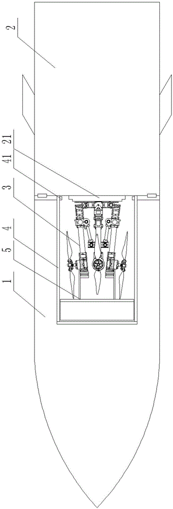
图2示出根据本发明一种优选实施方式的搭载旋翼无人机的分离式运载系统承载段和动力段分离,旋翼无人机向外弹出时的结构示意图;2 shows a schematic structural diagram when the carrying section and the power section of the detachable carrying system carrying the rotor drone are separated according to a preferred embodiment of the present invention, and the rotor drone pops out;
图3示出根据本发明一种优选实施方式的搭载旋翼无人机的分离式运载系统中支撑筒截面图;FIG. 3 shows a cross-sectional view of a support cylinder in a separate delivery system carrying a rotary-wing UAV according to a preferred embodiment of the present invention;
图4示出根据本发明一种优选实施方式的搭载旋翼无人机的分离式运载系统中旋翼无人机结构示意图。FIG. 4 shows a schematic structural diagram of a rotary-wing drone in a separate delivery system carrying a rotary-wing drone according to a preferred embodiment of the present invention.
附图标号说明:Description of reference numbers:
1-承载段1 - Bearing segment
2-动力段2-Power segment
21-弹性垫21- Elastic pad
3-旋翼无人机3-Rotor UAV
31-机架31-Rack
32-旋臂32-swivel arm
321-光杆段321 - Polished Rod Section
322-环形滑套322-ring sliding sleeve
33-连接盘33-connection plate
34-连杆34-Link
35-驱动电机35-drive motor
36-螺旋桨36-Propeller
4-套筒4-Sleeve
41-限位挡块41-Limit stop
5-弹射部5-Ejection Department
51-底座51-base
52-支撑筒52-Support cylinder
53-承托板53-bearing plate
具体实施方式Detailed ways
下面通过附图和实施例对本发明进一步详细说明。通过这些说明,本发明的特点和优点将变得更为清楚明确。The present invention will be further described in detail below through the accompanying drawings and embodiments. The features and advantages of the present invention will become more apparent from these descriptions.
在这里专用的词“示例性”意为“用作例子、实施例或说明性”。这里作为“示例性”所说明的任何实施例不必解释为优于或好于其它实施例。尽管在附图中示出了实施例的各种方面,但是除非特别指出,不必按比例绘制附图。The word "exemplary" is used exclusively herein to mean "serving as an example, embodiment, or illustration." Any embodiment described herein as "exemplary" is not necessarily to be construed as preferred or advantageous over other embodiments. While various aspects of the embodiments are shown in the drawings, the drawings are not necessarily drawn to scale unless otherwise indicated.
本发明所述的铰接是指具有足够强度,不易断开的连接关系,这种连接允许彼此连接的两者之间做相对转动;本发明中一般通过转轴或者合页实现所述铰接。The hinge in the present invention refers to a connection relationship with sufficient strength that is not easy to be disconnected, and this connection allows relative rotation between the two connected to each other; in the present invention, the hinge is generally realized by a rotating shaft or a hinge.
根据本发明提供的搭载旋翼无人机的分离式运载系统,如图1、图2中所示,该弹射装置包括该系统包括可分离的承载段1和动力段2。According to the detachable carrying system for carrying a rotary-wing UAV provided by the present invention, as shown in FIG. 1 and FIG. 2 , the ejection device includes that the system includes a
其中,所述承载段1设置在所述动力段2的前端,Wherein, the
在所述承载段1中安装有可容纳旋翼无人机3套筒4,A
当所述运载系统到达预定空域后,承载段1和动力段2分离,所述套筒4将其内的旋翼无人机3弹出。When the carrying system reaches the predetermined airspace, the carrying
在所述套筒4中设置有弹射部5,An
所述旋翼无人机3折叠收纳后固定在弹射部5上,并位于套筒4内部,The
所述弹射部5能够从套筒4的底部弹射至套筒4的顶部,进而将旋翼无人机3从所述套筒4中弹出。将所述套筒设置在运载系统侧部,当旋翼无人机3从所述套筒4中弹出后,旋翼无人机3整体即位于运载系统之外。在所述套筒4内侧,在靠近开口处设置有限位挡块41,用以防止弹射部5完全从套筒4中弹出。The
在一个优选的实施方式中,所述运载系统在到达预定空域时放开对所述旋翼无人机的禁锢,使得旋翼无人机与运载系统脱离,此时无人机距离预定的工作区域的距离较小,能够快速抵达;从而使得从接收到任务指令和相关目标信息到无人机就位并开始工作这段准备及航行时间大幅缩短,实现旋翼无人机的快速反应、快速机动,能够用于处置突发的紧急任务。本发明中放开对所述旋翼无人机的禁锢的方式为运载系统分离,即承载段1和动力段2分离。In a preferred embodiment, the delivery system releases the restraint on the rotor drone when it reaches the predetermined airspace, so that the rotor drone is separated from the delivery system, and the drone is at a distance from the predetermined working area. The distance is small, and it can be reached quickly; thus, the preparation and navigation time from receiving the mission instruction and relevant target information to the UAV being in place and starting to work is greatly shortened, and the rapid response and rapid maneuvering of the rotor UAV can be realized. Used to deal with emergencies in emergencies. In the present invention, the way to release the confinement of the rotor UAV is to separate the carrying system, that is, the carrying
本发明所述的运载系统类似于火箭或火箭弹,其飞行原理与火箭类似,是通过火箭发动机喷射工质产生的反作用力向前推进的飞行器;其发射方式与火箭弹类似,所述火箭弹是由火箭筒或者火箭炮发射出的弹药,其中弹药的战斗部需替换为本发明中所述旋翼无人机或者套筒。The delivery system of the present invention is similar to a rocket or a rocket, and its flight principle is similar to that of a rocket. It is the ammunition fired by the rocket launcher or the rocket launcher, wherein the warhead of the ammunition needs to be replaced with the rotary-wing drone or the sleeve described in the present invention.
优选地,所述套筒4设置在承载段1的尾部,与动力段2相连;在运载系统中可以设置多个所述套筒4,该多个套筒需要并排设置,都与动力段2相连;Preferably, the
当所述承载段1和动力段2分离后,所述套筒4的开口端裸露在外,所述套筒4的顶部/开口端处再无遮挡,其内的旋翼无人机可以自由弹出,即直接弹出至运载系统之外。When the load-
本发明中,通过所述底座51与套筒4配合将底座3弹射至套筒4的顶部,所述套筒4和底座3之间可以通过任选的多种方式进行弹射,如设置压缩弹簧作为动力进行弹射,设置弹性橡皮筋作为动力进行弹射,设置电磁铁,利用斥力或者引力进行弹射,还可以利用电磁感应线圈为动力进行弹射,可以根据具体的工作要求进行选择。In the present invention, the
承载段1和动力段2在运载系统达到预定空域时开启,以便于弹射部5将旋翼无人机3从运载系统中弹出;所述承载段1和动力段2之间通过锁扣连接,优选地,二者之间还设置有密封圈,当到达预定空域后,控制所述锁扣解锁,承载段1和动力段2自然分离;优选地,在承载段1和动力段2之间设置有压缩弹簧等弹性设备,当所述扣解锁后,能够加速承载段1和动力段2之间的分离。The carrying
在一个优选的实施方式中,所述弹射部5包括位于底部的底座51和位于底座51上方的支撑筒52,在所述支撑筒52内部设置有承托板53;In a preferred embodiment, the
通过所述底座本体31与套筒4配合将底座3弹射至套筒4的顶部,Through the cooperation of the
通过所述支撑筒52禁锢旋翼无人机3,The
通过所述承托板53推动旋翼无人机3,使得与旋翼无人机3与支撑筒52脱离。The rotary-
具体来说,如图1和图3中所示,所述支撑筒52尺寸与所述旋翼无人机旋臂折叠后围成的类圆形结构的外径尺寸基本一致,使得该支撑筒52刚好能够嵌入到无人机旋臂与螺旋桨之间,进而使得旋臂32的端部抵接在支撑筒52的内圈壁面上,支撑筒52能够阻碍旋臂32旋转,进而阻碍旋臂32回弹至水平位置,从而实现对无人机的禁锢;所述支撑筒52的高度值为30-50mm,即支撑筒52的最高处与承托板53之间的距离为30-50mm,由于所述承托板53可以在竖直方向上移动,在计算该高度/距离时,所述承托板53处于可能的最低点。Specifically, as shown in FIG. 1 and FIG. 3 , the size of the
当所述运载系统禁锢无人机时,所述承托板53位于旋臂32的下方,承托板53与旋臂之间的距离较小,一般小于10mm,且所述承托板53可以在竖直方向上移动,其移动行程至少为30-50mm,即随着承托板53的移动,承托板53能够将无人机的旋臂从承托座2中推出,由于承托板53的移动速度较高,无人机与承托座2脱离时,无人机具有一定的初始速度,能够继续沿着该方向移动一定距离。When the UAV is imprisoned by the delivery system, the
所述承托板53可以通过电磁铁产生的斥力作为动力,也可以通过压缩弹簧作为动力,可以根据实际情况自行选择,能够实现上述往复移动并推动旋翼无人机的功能即可。The
在一个优选的实施方式中,如图1、图2中所示,In a preferred embodiment, as shown in Figure 1 and Figure 2,
所述锁扣机构在收到分离指令后,放开承载段1和动力段2之间的锁紧,使得承载段1和动力段2之间分离,从而裸露出承载段1中的套筒及旋翼无人机;After receiving the separation instruction, the locking mechanism releases the locking between the bearing
优选地,所述运载系统中还设置有控制模块,该控制模块用于向所述锁扣机构发送分离指令,该控制模块可以基于时间信息生成并发出分离指令,也可以基于探测到的状态信息生成并发出分离指令,还可以基于地面指令生成并发出分离指令;Preferably, the carrying system is further provided with a control module, and the control module is used to send a separation instruction to the locking mechanism. The control module can generate and issue a separation command based on time information, or can also be based on detected state information. Generate and issue separation commands, and can also generate and issue separation commands based on ground commands;
其中,所述时间信息是指预装的在预定时间后生成并发出分离指令,一般在运载系统启动前,灌装该预定时间,如40s后生成并发出分离指令;Wherein, the time information refers to the pre-installed generation and issuance of a separation command after a predetermined time. Generally, before the launch of the carrier system, the predetermined time is filled, for example, a separation command is generated and issued after 40s;
所述探测到的状态信息是指运载系统探测到的其自身的位置信息和速度信息,主要通过GPS接收模块、北斗接收模块等卫星定位模块探测、获知运载系统自身的位置信息和速度信息等相关信息,当探测到的状态信息满足预设条件时生成并发出分离指令,如到达800m高度附近时生成并发出分离指令,或者到达东经116.3度,北纬39.95度附近时生成并发出分离指令,或者竖直方向速度值为0时生成并发出分离指令等;The detected status information refers to its own position information and speed information detected by the delivery system, mainly through GPS receiving module, Beidou receiving module and other satellite positioning modules to detect and learn the position information and speed information of the delivery system itself. When the detected state information meets the preset conditions, a separation command is generated and issued, such as when it reaches a height of 800m, a separation command is generated and issued, or a separation command is generated and issued when it reaches 116.3 degrees east longitude and 39.95 degrees north latitude, or a vertical separation command is generated and issued. When the speed value in the straight direction is 0, a separation command is generated and issued;
所述地面指令是指运载系统实时接收的由地面控制站发出的控制指令。The ground command refers to the control command sent by the ground control station received by the carrier system in real time.
在一个优选的实施方式中,如图1、图2中所示,在所述动力段2的顶部即与承载段1相接触的一端设置有弹性垫21;所述弹性垫41由橡胶或者聚高分子材料制成,既具有一定的弹性,也能够承载一定的作用力。In a preferred embodiment, as shown in FIG. 1 and FIG. 2 , an
在承载段1与动力段2未分离的情况下,所述弹性垫21与位于套筒4内部的旋翼无人机3抵接,从而将旋翼无人机3固定在套筒4中,防止旋翼无人机在运载系统中振动或者摆动。Under the condition that the
在一个优选的实施方式中,如图4中所示,该旋翼无人机包括机架31和旋臂32;本发明所述的旋翼无人机是指四旋翼无人机、六旋翼无人机或者八旋翼无人机;In a preferred embodiment, as shown in FIG. 4 , the rotary-wing drone includes a
该无人机在其旋臂32相对于机架31向下弯折时被禁锢在运载系统内,优选地,其弯折角度在90度左右时才能够使得无人机被禁锢在运载系统内;本发明中最优选的弯折角度是95度。The UAV is imprisoned in the delivery system when its
当所述运载系统放开对所述无人机的禁锢时,所述无人机的旋臂32自动回弹至水平位置,并启动工作;具体来说,当所述旋臂32在弹力作用下自动回弹至水平位置,此时旋臂上的电机启动工作,带动螺旋桨旋转,使得无人机尽快在该空域悬停,与此同时,无人机上的其他相关设备也都启动工作,如导航系统、GPS定位系统等等,以使得无人机尽快确定所处方位,并移动至目标位置,开始执行预定的作业任务。When the delivery system releases the restraint of the UAV, the
在一个优选的实施方式中,如图1和图4中所示,该无人机还包括设置在机架31正下方的连接盘33,In a preferred embodiment, as shown in FIG. 1 and FIG. 4 , the unmanned aerial vehicle further comprises a connecting
通过所述连接盘33在竖直方向上的往复移动来控制旋臂32向下弯折或者回弹至水平位置。当连接盘33向下移动时,带动旋臂32向下弯折,当连接盘33向上移动时,带动旋臂32回弹至水平位置;同样地,当旋臂32向下弯折时也可以带动连接盘33向下移动,当旋臂32回弹至水平位置时也可以带动连接盘33向上移动。Through the reciprocating movement of the connecting
具体来说,优选地,在所述连接盘33上设置有连杆34,Specifically, preferably, a connecting
所述连杆34一端与连接板3铰接,One end of the connecting
所述连杆34的另一端与旋臂32连接。连杆34的数量与旋臂32的数量一致,彼此一一对应。The other end of the connecting
进一步优选地,所述旋臂32包括光杆段321,Further preferably, the
在所述光杆段321上套设有环形滑套322,所述环形套筒122可以沿着光杆段321往复滑动,或者所述环形套筒122固定在所述光杆段321上;An annular sliding
所述连杆34与所述环形滑套322铰接,即所述连杆34通过环形滑套322与旋臂32铰接。The connecting
优选地,在所述连接板3和机架31上都设置有限位机构,使得旋臂只能在水平方向和向下弯折95度之间往复摆动。Preferably, a limiting mechanism is provided on both the connecting
优选地,在所述连接盘33和机架31之间设置有拉伸机构,Preferably, a stretching mechanism is provided between the connecting
所述拉伸机构用于拉动连接盘33向上靠近机架31,进而带动旋臂32回弹至水平位置。所述拉伸机构包括竖直设置的弹簧,该弹簧一直处于拉伸状态;当旋臂32向下弯折时,该拉伸机构中存储有较大的弹性势能,使得旋臂32上具有回复至水平位置的趋势,当限制、禁锢旋臂32的外力消失时,在该拉伸机构的作用下所述旋臂32可以较大的加速度从静止开始加速旋转,从向下弯折状态回弹至水平位置。The stretching mechanism is used to pull the connecting
进一步优选地,在连杆34一端与连接板3铰接和连杆34与所述环形滑套322铰接的两个铰接位置设置扭转弹簧,该扭转弹簧也是所述拉伸机构的一部分,通过所述扭转弹簧增加旋臂32从水平位置到弯折状态所需要克服的弹力,进而增加在旋臂322向下弯折时,该拉伸机构中存储的弹性势能;该扭转弹簧还能够使得连杆34及旋臂32上的受到多个方向的作用力,确保连杆34及旋臂32按照设定轨迹移动,进而增强该系统的可靠性,在预定空域中,放开对无人机的禁锢时,无人机的旋臂一定能够回弹至水平位置。Further preferably, a torsion spring is provided at the two hinge positions where one end of the connecting
在一个优选的实施方式中,如图1、图4中所示,在所述旋臂32的端部设置有驱动电机35和螺旋桨36,驱动电机35用于控制螺旋桨36旋转,当所述无人机被禁锢到运载系统中时,所述驱动电机35的控制电路处于待机状态;在旋臂与机架连接处设置有感应开关,当旋臂回复至水平位置时触发所述感应开关,当所述感应开关被触发后所述驱动电机35的控制电路接通,驱动电机35启动工作。该感应开关可以是电磁感应开关,也可以是机械触点开关,可以任意设置,只要能够实现上述功能即可。In a preferred embodiment, as shown in FIG. 1 and FIG. 4 , a
其中,旋臂32与螺旋桨36之间留有预定空隙,所述驱动电机35有一部分埋置在旋臂32中,另一部分裸露在外,在所述裸露在外部分的端部安装螺旋桨36。A predetermined gap is left between the
优选地,所述旋臂32设置有多个,优选为4-8个,Preferably, there are multiple, preferably 4-8, said rotating
当所述无人机被禁锢在运载系统内时,所述旋臂32对应的多个所述预定空隙呈圆形排布;运载系统通过该空隙禁锢所述无人机,即在该空隙内嵌入阻碍旋臂32回弹至水平位置的支撑筒52,在旋臂上弹力的作用下,无人机整体即被固定、禁锢在运载系统中。When the UAV is imprisoned in the delivery system, the plurality of predetermined gaps corresponding to the
本发明还提供搭载旋翼无人机的分离式运载系统搭载并弹射旋翼无人机的方法,该方法包括如下步骤:The present invention also provides a method for carrying and ejecting the rotor unmanned aerial vehicle by the detachable carrier system carrying the rotor unmanned aerial vehicle. The method comprises the following steps:
步骤1,将旋翼无人机3禁锢在套筒4内的弹射部5上,并将承载段1与动力段2固接为一体;
步骤2,运载系统飞行至预定空域时承载段1与动力段2分离;
步骤3,弹射部5从套筒4的底部弹射至套筒4的顶部;
步骤4,承托板53向上移动将旋翼无人机3从支撑筒52中推出,进而使得旋翼无人机3在运载系统外部与支撑筒52脱离,旋翼无人机的旋臂32回弹至水平位置,并启动工作。
以上结合了优选的实施方式对本发明进行了说明,不过这些实施方式仅是范例性的,仅起到说明性的作用。在此基础上,可以对本发明进行多种替换和改进,这些均落入本发明的保护范围内。The present invention has been described above with reference to the preferred embodiments, but these embodiments are merely exemplary and serve only for illustrative purposes. On this basis, various substitutions and improvements can be made to the present invention, which all fall within the protection scope of the present invention.
Claims (10)
Priority Applications (1)
| Application Number | Priority Date | Filing Date | Title |
|---|---|---|---|
| CN201810996785.0A CN110871904B (en) | 2018-08-29 | 2018-08-29 | Separated carrying system for carrying rotor unmanned aerial vehicle |
Applications Claiming Priority (1)
| Application Number | Priority Date | Filing Date | Title |
|---|---|---|---|
| CN201810996785.0A CN110871904B (en) | 2018-08-29 | 2018-08-29 | Separated carrying system for carrying rotor unmanned aerial vehicle |
Publications (2)
| Publication Number | Publication Date |
|---|---|
| CN110871904A true CN110871904A (en) | 2020-03-10 |
| CN110871904B CN110871904B (en) | 2023-05-02 |
Family
ID=69714607
Family Applications (1)
| Application Number | Title | Priority Date | Filing Date |
|---|---|---|---|
| CN201810996785.0A Expired - Fee Related CN110871904B (en) | 2018-08-29 | 2018-08-29 | Separated carrying system for carrying rotor unmanned aerial vehicle |
Country Status (1)
| Country | Link |
|---|---|
| CN (1) | CN110871904B (en) |
Cited By (3)
| Publication number | Priority date | Publication date | Assignee | Title |
|---|---|---|---|---|
| CN113086235A (en) * | 2021-04-26 | 2021-07-09 | 北京理工大学 | Tubular vertical ejection type ejection unmanned aerial vehicle, ejection system and implementation method thereof |
| CN114987771A (en) * | 2022-08-05 | 2022-09-02 | 西安羚控电子科技有限公司 | Unmanned aerial vehicle and carrier buffering separator |
| CN116499307A (en) * | 2023-05-17 | 2023-07-28 | 天津天羿科技有限公司 | Cylinder-type launched rotor patrol projectile and working method thereof |
Citations (11)
| Publication number | Priority date | Publication date | Assignee | Title |
|---|---|---|---|---|
| GB8420098D0 (en) * | 1983-08-11 | 1988-10-12 | Secr Defence | Improvements in/relating to unmanned aircraft |
| US6286410B1 (en) * | 1999-05-10 | 2001-09-11 | The United States Of Americas As Represented By The Secretary Of The Navy | Buoyantly propelled submerged canister for air vehicle launch |
| US20120205488A1 (en) * | 2011-02-16 | 2012-08-16 | Sparton Corporation | Unmanned aerial vehicle launch system |
| WO2015127178A1 (en) * | 2014-02-21 | 2015-08-27 | Lockheed Martin Corporation | Payload launcher and autonomous underwater vehicle |
| CN105035321A (en) * | 2015-07-08 | 2015-11-11 | 中国电子科技集团公司第二十七研究所 | Miniature cylindrical launched unmanned plane and launcher |
| US20160137312A1 (en) * | 2014-05-06 | 2016-05-19 | Osterhout Group, Inc. | Unmanned aerial vehicle launch system |
| CN106005414A (en) * | 2016-07-27 | 2016-10-12 | 北京机械设备研究所 | Relief goods carrier based on gun launching |
| CN106184704A (en) * | 2016-08-08 | 2016-12-07 | 北京航空航天大学 | One is applicable to rocket-propelled quadrotor |
| US20170057635A1 (en) * | 2015-09-02 | 2017-03-02 | The Boeing Company | Drone launch systems and methods |
| CN106965913A (en) * | 2017-04-05 | 2017-07-21 | 西北工业大学 | A kind of delivery of unmanned plane under water and catapult-launching gear |
| CN107990787A (en) * | 2017-12-05 | 2018-05-04 | 佛山市海科云筹信息技术有限公司 | A kind of anti-UAV system |
-
2018
- 2018-08-29 CN CN201810996785.0A patent/CN110871904B/en not_active Expired - Fee Related
Patent Citations (11)
| Publication number | Priority date | Publication date | Assignee | Title |
|---|---|---|---|---|
| GB8420098D0 (en) * | 1983-08-11 | 1988-10-12 | Secr Defence | Improvements in/relating to unmanned aircraft |
| US6286410B1 (en) * | 1999-05-10 | 2001-09-11 | The United States Of Americas As Represented By The Secretary Of The Navy | Buoyantly propelled submerged canister for air vehicle launch |
| US20120205488A1 (en) * | 2011-02-16 | 2012-08-16 | Sparton Corporation | Unmanned aerial vehicle launch system |
| WO2015127178A1 (en) * | 2014-02-21 | 2015-08-27 | Lockheed Martin Corporation | Payload launcher and autonomous underwater vehicle |
| US20160137312A1 (en) * | 2014-05-06 | 2016-05-19 | Osterhout Group, Inc. | Unmanned aerial vehicle launch system |
| CN105035321A (en) * | 2015-07-08 | 2015-11-11 | 中国电子科技集团公司第二十七研究所 | Miniature cylindrical launched unmanned plane and launcher |
| US20170057635A1 (en) * | 2015-09-02 | 2017-03-02 | The Boeing Company | Drone launch systems and methods |
| CN106005414A (en) * | 2016-07-27 | 2016-10-12 | 北京机械设备研究所 | Relief goods carrier based on gun launching |
| CN106184704A (en) * | 2016-08-08 | 2016-12-07 | 北京航空航天大学 | One is applicable to rocket-propelled quadrotor |
| CN106965913A (en) * | 2017-04-05 | 2017-07-21 | 西北工业大学 | A kind of delivery of unmanned plane under water and catapult-launching gear |
| CN107990787A (en) * | 2017-12-05 | 2018-05-04 | 佛山市海科云筹信息技术有限公司 | A kind of anti-UAV system |
Non-Patent Citations (1)
| Title |
|---|
| 王婵: "大学航模队都玩什么?"黑精灵"变体无人机", 《中国航空新闻网》 * |
Cited By (5)
| Publication number | Priority date | Publication date | Assignee | Title |
|---|---|---|---|---|
| CN113086235A (en) * | 2021-04-26 | 2021-07-09 | 北京理工大学 | Tubular vertical ejection type ejection unmanned aerial vehicle, ejection system and implementation method thereof |
| CN113086235B (en) * | 2021-04-26 | 2022-05-17 | 北京理工大学 | A tubular vertical ejection type ejection unmanned aerial vehicle and its ejection system and implementation method |
| CN114987771A (en) * | 2022-08-05 | 2022-09-02 | 西安羚控电子科技有限公司 | Unmanned aerial vehicle and carrier buffering separator |
| CN114987771B (en) * | 2022-08-05 | 2022-11-01 | 西安羚控电子科技有限公司 | Unmanned aerial vehicle and carrier buffering separator |
| CN116499307A (en) * | 2023-05-17 | 2023-07-28 | 天津天羿科技有限公司 | Cylinder-type launched rotor patrol projectile and working method thereof |
Also Published As
| Publication number | Publication date |
|---|---|
| CN110871904B (en) | 2023-05-02 |
Similar Documents
| Publication | Publication Date | Title |
|---|---|---|
| US12466558B2 (en) | Device and method to intercept an aerial vehicle | |
| US10096255B1 (en) | Damage avoidance system for unmanned aerial vehicle using stored energy from descent | |
| US10065726B1 (en) | Unmanned aerial vehicles with multiple configurations | |
| US10814968B2 (en) | Hinge mechanism for a weight-shifting coaxial helicopter | |
| US9073645B2 (en) | Apparatus and method for retrieving unmanned aerial vehicles | |
| CN110871904B (en) | Separated carrying system for carrying rotor unmanned aerial vehicle | |
| WO2006086079A1 (en) | Uav arresting hook for use with uav recovery system | |
| US11591087B2 (en) | Unmanned aerial vehicle with ducted rotors | |
| CN105416526A (en) | Unmanned aerial vehicle rescue device for water area | |
| CN114044142B (en) | Unmanned aerial vehicle air basis storage and delivery integrated device | |
| CN110857148A (en) | Rotor unmanned aerial vehicle ejection device on carrying system | |
| CN109229404B (en) | Unmanned aerial vehicle slide rail type aerial rapid recovery system | |
| US11591112B2 (en) | Device for catching and launching an unmanned aerial vehicle | |
| CN108088313A (en) | A kind of unmanned plane intercepting system | |
| CN110857146A (en) | Carry on many rotor unmanned aerial vehicle's delivery system | |
| CN110857149A (en) | Retrievable delivery system for rotary-wing UAV | |
| CN112874770A (en) | Drum-type launching rotor craft | |
| CN110683069A (en) | Carry on rotor unmanned aerial vehicle's arrow machine system | |
| CN110683071A (en) | The delivery system of the rotary-wing UAV | |
| JP7506368B2 (en) | Aircraft take-off and landing system, take-off and landing gear for aircraft, and aircraft | |
| CN110865404B (en) | Target positioning system for cooperative operation of multiple rotor unmanned aerial vehicles | |
| CN110683070A (en) | Arrow-mounted rotor drone | |
| CN214649037U (en) | Air-drop system installed on portable rotor unmanned aerial vehicle | |
| CN110861781A (en) | Rocket-borne rotor unmanned aerial vehicle control system | |
| JP6918384B1 (en) | Ball launcher |
Legal Events
| Date | Code | Title | Description |
|---|---|---|---|
| PB01 | Publication | ||
| PB01 | Publication | ||
| SE01 | Entry into force of request for substantive examination | ||
| SE01 | Entry into force of request for substantive examination | ||
| GR01 | Patent grant | ||
| GR01 | Patent grant | ||
| CB03 | Change of inventor or designer information |
Inventor after: Wang Hao Inventor after: Qiu Ziyi Inventor after: Xu Weixiong Inventor after: Cui Ling Inventor after: Wang Yadong Inventor after: Jiang Jun Inventor after: Wang Jiang Inventor before: Wang Hao Inventor before: Xu Weixiong Inventor before: Cui Ling Inventor before: Wang Yadong Inventor before: Jiang Jun Inventor before: Qiu Ziyi Inventor before: Wang Jiang |
|
| CB03 | Change of inventor or designer information | ||
| CF01 | Termination of patent right due to non-payment of annual fee |
Granted publication date: 20230502 |
|
| CF01 | Termination of patent right due to non-payment of annual fee |