CN110707828A - Wireless charging receiving device, wireless charging implementation method and mobile terminal - Google Patents
Wireless charging receiving device, wireless charging implementation method and mobile terminal Download PDFInfo
- Publication number
- CN110707828A CN110707828A CN201810746388.8A CN201810746388A CN110707828A CN 110707828 A CN110707828 A CN 110707828A CN 201810746388 A CN201810746388 A CN 201810746388A CN 110707828 A CN110707828 A CN 110707828A
- Authority
- CN
- China
- Prior art keywords
- wireless charging
- module
- wireless
- charging
- coil
- Prior art date
- Legal status (The legal status is an assumption and is not a legal conclusion. Google has not performed a legal analysis and makes no representation as to the accuracy of the status listed.)
- Pending
Links
- 238000000034 method Methods 0.000 title claims abstract description 16
- 238000006243 chemical reaction Methods 0.000 claims abstract description 27
- 230000005674 electromagnetic induction Effects 0.000 claims abstract description 17
- 230000004907 flux Effects 0.000 claims description 35
- 238000001514 detection method Methods 0.000 claims description 22
- 230000006698 induction Effects 0.000 claims description 22
- 230000008878 coupling Effects 0.000 description 10
- 238000010168 coupling process Methods 0.000 description 10
- 238000005859 coupling reaction Methods 0.000 description 10
- 238000010438 heat treatment Methods 0.000 description 10
- 238000010586 diagram Methods 0.000 description 9
- 238000006073 displacement reaction Methods 0.000 description 8
- 230000007423 decrease Effects 0.000 description 3
- 230000009977 dual effect Effects 0.000 description 3
- 238000005516 engineering process Methods 0.000 description 3
- 230000020169 heat generation Effects 0.000 description 3
- 230000008569 process Effects 0.000 description 3
- 229910000859 α-Fe Inorganic materials 0.000 description 3
- 229910001289 Manganese-zinc ferrite Inorganic materials 0.000 description 2
- JIYIUPFAJUGHNL-UHFFFAOYSA-N [O--].[O--].[O--].[O--].[O--].[O--].[O--].[O--].[O--].[O--].[O--].[O--].[O--].[O--].[O--].[O--].[O--].[O--].[O--].[O--].[Mn++].[Mn++].[Mn++].[Fe+3].[Fe+3].[Fe+3].[Fe+3].[Fe+3].[Fe+3].[Fe+3].[Fe+3].[Fe+3].[Fe+3].[Zn++].[Zn++] Chemical compound [O--].[O--].[O--].[O--].[O--].[O--].[O--].[O--].[O--].[O--].[O--].[O--].[O--].[O--].[O--].[O--].[O--].[O--].[O--].[O--].[Mn++].[Mn++].[Mn++].[Fe+3].[Fe+3].[Fe+3].[Fe+3].[Fe+3].[Fe+3].[Fe+3].[Fe+3].[Fe+3].[Fe+3].[Zn++].[Zn++] JIYIUPFAJUGHNL-UHFFFAOYSA-N 0.000 description 2
- 230000005540 biological transmission Effects 0.000 description 2
- 239000000463 material Substances 0.000 description 2
- 230000035699 permeability Effects 0.000 description 2
- RYGMFSIKBFXOCR-UHFFFAOYSA-N Copper Chemical compound [Cu] RYGMFSIKBFXOCR-UHFFFAOYSA-N 0.000 description 1
- 150000001875 compounds Chemical class 0.000 description 1
- 230000000694 effects Effects 0.000 description 1
- 230000005611 electricity Effects 0.000 description 1
- 238000002955 isolation Methods 0.000 description 1
- 229910052751 metal Inorganic materials 0.000 description 1
- 239000002184 metal Substances 0.000 description 1
- 230000008961 swelling Effects 0.000 description 1
- 238000012795 verification Methods 0.000 description 1
Images
Classifications
-
- H—ELECTRICITY
- H02—GENERATION; CONVERSION OR DISTRIBUTION OF ELECTRIC POWER
- H02J—CIRCUIT ARRANGEMENTS OR SYSTEMS FOR SUPPLYING OR DISTRIBUTING ELECTRIC POWER; SYSTEMS FOR STORING ELECTRIC ENERGY
- H02J50/00—Circuit arrangements or systems for wireless supply or distribution of electric power
- H02J50/10—Circuit arrangements or systems for wireless supply or distribution of electric power using inductive coupling
-
- H—ELECTRICITY
- H02—GENERATION; CONVERSION OR DISTRIBUTION OF ELECTRIC POWER
- H02J—CIRCUIT ARRANGEMENTS OR SYSTEMS FOR SUPPLYING OR DISTRIBUTING ELECTRIC POWER; SYSTEMS FOR STORING ELECTRIC ENERGY
- H02J50/00—Circuit arrangements or systems for wireless supply or distribution of electric power
- H02J50/40—Circuit arrangements or systems for wireless supply or distribution of electric power using two or more transmitting or receiving devices
- H02J50/402—Circuit arrangements or systems for wireless supply or distribution of electric power using two or more transmitting or receiving devices the two or more transmitting or the two or more receiving devices being integrated in the same unit, e.g. power mats with several coils or antennas with several sub-antennas
-
- H—ELECTRICITY
- H02—GENERATION; CONVERSION OR DISTRIBUTION OF ELECTRIC POWER
- H02J—CIRCUIT ARRANGEMENTS OR SYSTEMS FOR SUPPLYING OR DISTRIBUTING ELECTRIC POWER; SYSTEMS FOR STORING ELECTRIC ENERGY
- H02J7/00—Circuit arrangements for charging or depolarising batteries or for supplying loads from batteries
- H02J7/02—Circuit arrangements for charging or depolarising batteries or for supplying loads from batteries for charging batteries from AC mains by converters
- H02J7/04—Regulation of charging current or voltage
Landscapes
- Engineering & Computer Science (AREA)
- Power Engineering (AREA)
- Computer Networks & Wireless Communication (AREA)
- Charge And Discharge Circuits For Batteries Or The Like (AREA)
Abstract
The embodiment of the invention discloses a wireless charging receiving device, a wireless charging realization method and a mobile terminal, wherein the wireless charging receiving device comprises a wireless charging conversion module, a charging management module, a voltage combining module and at least two wireless charging receiving coils, wherein the at least two wireless charging receiving coils are used for being coupled with a wireless charging transmitting coil in the wireless charging transmitting device and outputting an alternating current electromagnetic induction signal to the voltage combining module; the voltage combining module is used for performing voltage superposition on the alternating current electromagnetic induction signals output by the at least two wireless charging receiving coils and outputting the superposed alternating current signals to the wireless charging conversion module; the wireless charging conversion module is used for converting the received alternating current signal into a direct current signal and outputting the direct current signal to the charging management module; the charging management module is used for charging the battery by using the received direct current signal.
Description
Technical Field
The present application relates to the field of charging, and in particular, to a wireless charging receiving device, a method for implementing wireless charging, and a mobile terminal.
Background
The mobile terminal wireless charging technology is to charge the mobile terminal in a wireless manner, and generally includes an electromagnetic induction manner and a magnetic resonance manner, where the electromagnetic induction manner is common.
For the wireless charging technology of the electromagnetic induction mode, at present, the application of the medium-power wireless charging with the receiving end power being more than 5W and less than 15W is more, but in practical application, the application is accompanied with a serious heating condition, for example, when a 7.5W quick charging of a certain brand is tested, the charging can be maintained for only 8-10 minutes, and at this time, the temperature of the mobile phone reaches more than 60 ℃.
In the test of wireless charging products below 5W, it was also found that when the output current is large, the heat generation is also very serious, for example, the output current is 1A, the charger surface has reached 56 degrees in about one hour, and the temperature of the battery sensor has also reached 50 degrees.
The mobile terminal generates heat seriously during wireless charging, so that on one hand, the mobile terminal is very hot after being taken down from a charging panel, and the user experience is influenced; on the other hand, long charging times may cause battery swelling, affecting battery life.
The conventional technology for solving the heating problem of wireless charging and quick charging at present is to arrange a metal separating device between a wireless charging receiving coil and a battery to block magnetic lines and prevent the magnetic lines from reaching the battery. The "metal-insulated" device is made of a ferrite material having a high magnetic permeability, and a manganese-zinc ferrite material is generally used because of its high initial magnetic permeability. However, since the manganese-zinc ferrite has a low resistivity, eddy currents are still generated in the ferrite, which causes the ferrite to generate heat. The method cannot fundamentally avoid the situation of heating during wireless charging and quick charging.
Disclosure of Invention
The embodiment of the invention provides a wireless charging receiving device, a wireless charging implementation method and a mobile terminal, and aims to achieve low-heat wireless charging.
The embodiment of the invention provides a wireless charging receiving device, which comprises a wireless charging conversion module, a charging management module, a voltage combining module and at least two wireless charging receiving coils, wherein the wireless charging conversion module and the charging management module are connected with each other, and the wireless charging receiving coils are connected with each other through the voltage combining module
The at least two wireless charging receiving coils are respectively connected with the voltage combining module and are used for being coupled with wireless charging transmitting coils in a wireless charging transmitting device and outputting alternating current electromagnetic induction signals to the voltage combining module;
the voltage combining module is connected with the wireless charging conversion module and is used for performing voltage superposition on the alternating current electromagnetic induction signals output by the at least two wireless charging receiving coils and outputting the superposed alternating current signals to the wireless charging conversion module;
the wireless charging conversion module is used for converting the received alternating current signal into a direct current signal and outputting the direct current signal to the charging management module;
the charging management module is used for charging the battery by using the received direct current signal.
The embodiment of the invention also provides a method for realizing wireless charging, which comprises the following steps
Performing voltage superposition on alternating current electromagnetic induction signals output by at least two wireless charging receiving coils;
converting the alternating current signal obtained after superposition into a direct current signal;
and charging the battery by using the direct current signal.
The embodiment of the invention also provides a mobile terminal which comprises the wireless charging receiving device.
The wireless charging receiving device comprises a wireless charging conversion module, a charging management module, a voltage combination module and at least two wireless charging receiving coils, wherein the wireless charging conversion module and the charging management module are connected with each other; the voltage combining module is connected with the wireless charging conversion module and is used for performing voltage superposition on the alternating current electromagnetic induction signals output by the at least two wireless charging receiving coils and outputting the superposed alternating current signals to the wireless charging conversion module; the wireless charging conversion module is used for converting the received alternating current signal into a direct current signal and outputting the direct current signal to the charging management module; the charging management module is used for charging the battery by using the received direct current signal. By the embodiment of the invention, the serious heating condition existing in the conventional wireless charging quick charging can be improved and reduced, and the low-heating wireless charging is realized.
Additional features and advantages of the invention will be set forth in the description which follows, and in part will be obvious from the description, or may be learned by practice of the invention. The objectives and other advantages of the invention will be realized and attained by the structure particularly pointed out in the written description and claims hereof as well as the appended drawings.
Drawings
The accompanying drawings are included to provide a further understanding of the invention and are incorporated in and constitute a part of this specification, illustrate embodiments of the invention and together with the example serve to explain the principles of the invention and not to limit the invention.
Fig. 1 is a schematic diagram of a single coil wireless charging scheme;
FIG. 2 is a schematic diagram of a multiple coil arrangement of an embodiment of the present invention;
fig. 3 is a schematic diagram illustrating a voltage combining module according to an embodiment of the present invention;
fig. 4 is a schematic diagram of a wireless charge receiving device according to an embodiment of the present invention;
fig. 5(a) is a schematic diagram of a wireless charging receiving coil being a single coil or superposed;
fig. 5(b) is a schematic diagram of the wireless charging receiving coil being a double coil and being staggered;
FIG. 6 is a graph of coupling factor as a function of receive coil shift distance;
fig. 7 is a schematic view of a wireless charge receiving device according to another embodiment of the present invention;
FIG. 8(a) is a schematic diagram of a dual coil staggering scheme with the geometric center coinciding with the center of the wireless charging transmit coil;
FIG. 8(b) is a schematic illustration of the shift in the dual coil staggering scheme;
fig. 9 is a flowchart of a method for implementing wireless charging according to an embodiment of the present invention;
fig. 10 is a flowchart of a method for implementing wireless charging according to an application example of the present invention.
Detailed Description
In order to make the objects, technical solutions and advantages of the present invention more apparent, embodiments of the present invention will be described in detail below with reference to the accompanying drawings. It should be noted that the embodiments and features of the embodiments in the present application may be arbitrarily combined with each other without conflict.
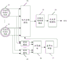
At present, a single-coil scheme is generally adopted in a wireless charging scheme, and is located at a central position of a battery, as shown in fig. 1, wherein a wireless charging transmitting device includes a transmitting module 11 and a wireless charging transmitting coil 12, wherein the transmitting module 11 receives power supplied by a power supply and outputs an electrical signal to the wireless charging transmitting coil 12; the wireless charging receiving device comprises a wireless charging receiving coil 21, a wireless charging conversion module 22 and a charging management module 23, wherein the wireless charging receiving coil 21 is coupled with the wireless charging transmitting coil 12 and outputs an alternating current electromagnetic induction signal to the wireless charging conversion module 22, the wireless charging conversion module 22 converts the received alternating current signal into a direct current signal and outputs the direct current signal to the charging management module 23, and the charging management module 23 charges a battery by using the received direct current signal.
The single coil scheme of fig. 1 generates heat more seriously at the receiving coil end, and the coil is sensitive to the displacement degree, so that once the coil is dislocated to a certain degree, the phenomenon that the coil cannot be charged occurs.
The embodiment of the invention adopts at least two wireless charging receiving coils to reduce the heat generation. As shown in fig. 2, the wireless charging receiving apparatus according to the embodiment of the present invention includes a wireless charging converting module 22 and a charging managing module 23 connected to each other, and further includes a voltage combining module 24 and at least two wireless charging receiving coils 21, wherein the voltage combining module 24 is configured to combine a plurality of voltages to form a wireless charging receiving coil
The at least two wireless charging receiving coils 21 are respectively connected with the voltage combining module 24, and are used for being coupled with the wireless charging transmitting coil 12 in the wireless charging transmitting device and outputting alternating current electromagnetic induction signals to the voltage combining module 24;
the voltage combining module 24 is connected to the wireless charging conversion module 22, and is configured to perform voltage superposition on the ac electromagnetic induction signals output by the at least two wireless charging receiving coils 21, and output the superposed ac electromagnetic induction signals to the wireless charging conversion module 22;
the wireless charging conversion module 22 is configured to convert the received ac signal into a dc signal, and output the dc signal to the charging management module 23;
the charging management module 23 is configured to charge the battery with the received dc signal.
In the embodiment of the invention, a mode of a plurality of wireless charging receiving coils is adopted, compared with a single-coil scheme, the number of turns of each wireless charging receiving coil is reduced, and the current generated in each coil is correspondingly reduced, so that the heating temperature of the coil is reduced.
The following description will be given taking an example in which the wireless charging reception coil is a double coil.
The wireless charging transmitting coil 12 in the wireless charging transmitting device is a single coil, and the number of turns of the single coil is NaThe power supply provides an alternating current signal to the wireless charging transmitting coil 12 as follows:
wherein, IaIs the amplitude, w is the angular frequency, t is the time value, and phi is the initial phase.
The magnetic field strength generated by the wireless charging transmitting coil 12 in the space is:
B(r)=h(r)ia(2)
where h (r) is a coefficient related to a function r of the distance between a point in space and the center of the transmit coil.
Assume that the originally employed single-coil reception scheme has N turnsbIn the embodiment of the invention, the receiving end adopts two coils, the number of turns of each coil is reduced by half, and the number of turns of each coil isBut the area and the impedance are kept unchanged, the induced voltage generated in the wireless charging receiving coil by the changing magnetic field generated in the space by the alternating current is,
wherein k (r)b) As a function of the distance r from the center of the receiving coil and the transmitting coilbA coefficient of correlation.
The induced voltages generated on the two receiving coils are respectively ub1And ub2Because the frequency and the phase of the sine waves of the two induced voltages are the same, the voltage after passing through the voltage combining module is,
when the two coils are superposed, the induced voltage generated by the two coils is,
this voltage is the same as for the single coil solution, but the voltage generated by each single coil is half the voltage of the single coil solution, while the impedance of each coil remains unchanged, so the current generated in each coil is half the original current. So that the heat generated by each coilThe heat generated by the whole device is half of the original heat. Therefore, the wireless charging receiving device adopts two coils, and when the two coils are superposed, the heating of the mobile terminal can be obviously reduced.
The wireless charging receiving coil 21 may be wound with a copper wire or an FPC (Flexible Printed Circuit Board), and is coupled with a wireless charging transmitting device (e.g., a wireless charging cradle) to receive a high-frequency electromagnetic wave generated by the wireless charging transmitting device.
In an embodiment of the present invention, the voltage combining module may include: an addition operation circuit.
Since the frequencies and phases of the induced voltages generated by the plurality of wireless charging receiving coils 21 are the same, an addition circuit may be used in the voltage combining module to add the induced voltages generated by the plurality of coils to obtain an output voltage.
As shown in fig. 3, the wireless charging receiving coil adopts a dual coil as an example, and the addition circuit may include an integrated operational amplifier a and a first resistor R1A second resistance R2Third resistor R3And a fourth resistor RF. Two induced voltages u generated by the double coils1And u2And the voltage is added to the non-inverting terminal of the integrated operational amplifier to form a non-inverting input adding circuit as shown in fig. 3, and the voltage of the output terminal obtained by the circuit is:
output voltage u generated at the output terminaloThe voltage is converted into a dc signal by the wireless charging conversion module 22, and the output of the wireless charging conversion module 22 is usually a dc voltage signal of 5V, 9V or 12V.
The charging management module 23 charges the battery by using the dc signal output by the wireless charging conversion module 22.
In the embodiment of the present invention, the at least two wireless charging receiving coils 21 are disposed in an overlapping manner, and central axes of the at least two wireless charging receiving coils are overlapped or staggered.
In order to prevent the situation, in an embodiment of the present invention, the wireless charging receiving apparatus may further include a detection module, a decision module, and a baseband processor, which are sequentially connected to each other.
As shown in fig. 4, in a case that central axes of the at least two wireless charging receiving coils 21 coincide, the detection module 25 is connected to one of the at least two wireless charging receiving coils 21, and is configured to detect magnetic induction of the connected wireless charging receiving coil 21;
the decision module 26 is configured to determine that a cutoff charging standard is reached according to the magnetic induction intensity detected by the detection module 25, and notify the baseband processor 27 to stop wireless charging;
the baseband processor 27 is connected to the voltage combining module 24, and is configured to control the voltage combining module 24 to stop wireless charging according to the notification of the decision module 26.
Wherein, because the at least two wireless receiving coil that charges are overlapped and are placed, can only detect one of them magnetic induction.
The detection module 25 may employ a hall device. And measuring the magnetic induction intensity.
In an embodiment, the decision module 26 is configured to determine a maximum magnetic flux passing through the wireless charging receiving coil 21 according to the magnetic induction and an area of the wireless charging receiving coil, and determine that a cutoff charging criterion is met when the maximum magnetic flux is smaller than a first threshold.
The maximum value of the magnetic flux passing through the wireless charging receiving coil 21 can be obtained by multiplying the magnetic induction by the area of the wireless charging receiving coil 21.
The first threshold is a preset value and can be set according to actual heating and power requirements.
The decision module 26 may determine, in real time, a maximum magnetic flux value that the wireless charging receiving coil 21 passes through, notify the baseband processor 27 to stop the wireless charging when the maximum magnetic flux value is smaller than a first threshold, and notify the baseband processor 27 to perform the wireless charging when the maximum magnetic flux value is greater than or equal to the first threshold.
When the double coils are overlapped, the situation same as that of the single coil scheme exists, namely the double coils adopt tightly coupled coils, so that the dislocation degree of the coils is sensitive in the using process, once the coils are dislocated, the phenomenon of electricity charge can not occur, and certain influence is brought to user experience. Therefore, the double coils can be placed in a staggered manner.
As shown in fig. 5(a), a schematic diagram of a wireless charging receiving coil being a single coil or superposed, a tightly coupled coil is adopted.
Fig. 5(b) is a schematic diagram of the wireless charging receiving coil being a double coil and being placed in a staggered manner, where central axes of the two wireless charging receiving coils are staggered. In the embodiment of the invention, the staggered distance of the central axes of the two wireless charging receiving coils can be less than or equal to 20 mm. For example, it may be 10mm to 20 mm.
If the wireless charging receiving coil and the wireless charging transmitting coil are separated by a certain distance, only a part of magnetic flux generated by the transmitting coil can reach the receiving coil, and the purpose of electric energy transmission is achieved. The more magnetic flux the receiving coil receives, the higher the degree of coupling between the two coils. The level of coupling is expressed by a coupling factor k. The coupling factor is related to the distance between the two coils and their relative size, and also to the shape of the coils and the angle between them. If the central axes of the initial coils are aligned, any shift may result in a decrease in the k value.
The definition of the coupling factor is expressed as:
it is derived from a variation of the related common system of equations for coupled inductors:
wherein, U1And U2Representing the voltage experienced by the two coils, I1And I2Representing the current flowing in both coils, L1And L2Is the self-inductance of the two coils, L12The mutual inductance of the two coupling coils, and ω 2 π f is the angular frequency.
The coupling factor can be calculated from the existing equation for the open loop voltage u:
if the self-inductance values of the two coils are equal, then the open-loop voltages u and k are equal.
Fig. 6 illustrates the effect of displacement by way of example of a planar coil having a diameter of 30 mm. The figure shows a graph of the coupling factor obtained for two parallel coils at different offset distances in the horizontal direction.
As can be seen from fig. 6, the larger the coil shift distance, the lower the coupling factor and the correspondingly lower the transmission efficiency.
In the coil staggering scheme, the magnetic fluxes of the at least two wireless charging receiving coils are not the same, and the magnetic fluxes of the at least two wireless charging receiving coils are detected and calculated simultaneously, so that a plurality of detection modules are adopted, as shown in fig. 7, including at least two detection modules 25, a decision module 26 and a baseband processor 27, wherein the detection modules include at least two detection modules 25, a decision module 26 and a baseband processor 27, and
the detection modules 25 correspond to the wireless charging receiving coils 21 one by one, and each detection module 25 is connected with one wireless charging receiving coil 21 and is used for detecting the magnetic induction intensity of the connected wireless charging receiving coil 21;
the decision module 26 is configured to determine that a cutoff charging standard is reached according to the magnetic induction intensity detected by the detection module 25, and notify the baseband processor 27 to stop wireless charging;
the baseband processor 27 is connected to the voltage combining module 24, and is configured to control the voltage combining module 27 to stop wireless charging according to the notification of the decision module 26.
In an embodiment, the decision module 26 is configured to determine a maximum value of magnetic flux passed by each wireless charging receiving coil 21 according to the magnetic induction detected by each detection module 25 and the area of each wireless charging receiving coil 21, and determine that the cutoff charging criterion is reached when the sum of the maximum values of magnetic flux passed by each wireless charging receiving coil 21 is smaller than a second threshold.
The second threshold is a preset value and can be set according to actual heating and power requirements.
Accordingly, the baseband processor 27 is notified of wireless charging when the sum of the maximum values of the magnetic fluxes passed by each wireless charging reception coil 21 is greater than or equal to the second threshold value.
Taking the wireless charging receiving coil as an example, since when two coils are staggered, if the number of turns of the coil is the same as that when the two coils are overlapped, the generated induced voltage is lower than that when the two coils are overlapped, and at this time, the charging efficiency is reduced, in the embodiment of the invention, in order to ensure that the geometric center of the two coils is at the center, as shown in fig. 8(a), the generated induced voltage is the same as that when the two coils are overlapped, the number of turns of the coil is increased on the basis of the double-coil overlapping scheme, so as to ensure that the generated induced voltage is the same, and since the resistance of the coil is kept unchanged at this time, the induced voltage generated by each coil is also unchanged, so compared with the double-coil overlapping scheme, the heat generated by the coil. After the mobile terminal is displaced for a certain distance, as shown in fig. 8(b), since the magnetic flux of one of the two coils increases, the magnetic flux of the other coil decreases, and the magnetic flux of the double-coil overlapping scheme also decreases, the magnitudes of the magnetic fluxes of the two schemes after the mobile terminal is displaced can be theoretically compared, and the following verification process is performed:
since the magnetic flux Φ passing through the single turn coil in each receiver coil is approximately linearly related to the displacement distance d at a short distance from the center of the transmitter coil, assuming that the relationship is,
Φ=-k|d|+m (11)
wherein m is a constant.
Because the phenomenon of no charging occurs when the current wireless charging shifts by 5mm, analysis is performed by taking the staggered distance of the double coils as 10mm as an example, the number of turns of the coil of the single-coil scheme is assumed to be N, the number of turns of the coil of the double-coil superposition scheme is N/2, the number of turns of each coil of the staggered scheme is assumed to be Nd, and in order to ensure that the magnetic fluxes passing through the two schemes are the same when the two schemes are in the central position, namely phi1=Φ2The following relationship is established in that,
thus, one can obtain:
when the mobile terminal shifts to the right by a distance d1The double coil superposition scheme passes magnetic flux of
The magnetic flux passing through the double-coil staggered scheme is
Φ2=Nd×(-k|-5+d1|+m)+Nd×(-k|5+d1|+m) (15)
When shifting by a distance d1<At 5mm, equation 15 can be simplified to,
at this time, it is apparent that2>Φ1。
When shifting by a distance d1>At 5mm, equation 15 can be simplified to,
further isolation of the compound of formula 17 can be achieved,
when the coil displacement distance is short, the magnetic fluxes generated by the two coils are positive, so that the magnetic fluxes are positiveSo phi2>Φ1。
It can be seen from the above theory that when the displacement degree is closer to the center of the transmitting coil, the magnetic flux of the double-coil staggered scheme is larger than that of the overlapped scheme, so that the chargeable range of the double-coil staggered scheme is larger than that of the overlapped scheme, namely, the non-charging phenomenon caused by displacement can be improved by the staggered scheme.
In summary, in the coil superposition scheme, the number of turns of the coil is small, so that the heat generation of the receiving end can be obviously reduced, but the phenomenon of displacement and no charging is easy to occur; in the staggering scheme, the number of turns of each coil is properly selected, so that when the geometric center of each coil is located at the central position, the phenomenon of no charging caused by single coil displacement is improved under the condition that the generated induction voltage is not changed.
Correspondingly, as shown in fig. 9, the method for implementing wireless charging according to the embodiment of the present invention includes
Step 301, performing voltage superposition on alternating current electromagnetic induction signals output by at least two wireless charging receiving coils;
step 302, converting the alternating current signal obtained after superposition into a direct current signal;
step 303, charging the battery with the dc signal.
In an embodiment, the method further comprises:
detecting magnetic induction generated by one or more of the at least two wireless charging receive coils;
and determining that the standard of stopping charging is reached according to the magnetic induction intensity, and stopping wireless charging.
The maximum value of the magnetic flux passed by the wireless charging receiving coil can be determined according to the magnetic induction intensity and the area of the wireless charging receiving coil, and when the maximum value of the magnetic flux is smaller than a first threshold (when the wireless charging receiving coils are overlapped), or the sum of the maximum values of the magnetic flux passed by each wireless charging receiving coil is smaller than a second threshold (when the wireless charging receiving coils are staggered), the cut-off charging standard is determined to be reached.
In the embodiment of the invention, when the charging cut-off standard is reached, the wireless charging is stopped, so that the serious heating caused by the large transmitting power of the wireless charging transmitting device when the wire charging receiving coil is far away from the center of the wireless charging transmitting coil can be effectively prevented.
The following is a description of an application example.
As shown in fig. 10, the charging process may include the steps of:
wherein, in the coil superposition scheme, the maximum magnetic flux of only one receiving coil can be calculated, and for the staggered scheme, the maximum magnetic flux of each receiving coil is calculated and added;
The embodiment of the invention also provides a mobile terminal which comprises the mobile terminal antenna.
The mobile terminal may be implemented in various forms. For example, the mobile terminal described in the embodiments of the present invention may include a mobile terminal such as a mobile phone, a smart phone, a notebook computer, a digital broadcast receiver, a PDA (Personal digital assistant), a PAD (tablet computer), a PMP (Portable Media Player), a navigation device, and the like. However, it will be understood by those skilled in the art that the configuration according to the embodiment of the present invention can be applied to a fixed type terminal in addition to elements particularly used for moving purposes. And a fixed terminal such as a digital TV, a desktop computer, and the like.
Although the embodiments of the present invention have been described above, the above description is only for the convenience of understanding the present invention, and is not intended to limit the present invention. It will be understood by those skilled in the art that various changes in form and details may be made therein without departing from the spirit and scope of the invention as defined by the appended claims.
Claims (10)
1. The wireless charging receiving device comprises a wireless charging conversion module and a charging management module which are connected, and is characterized by further comprising a voltage combining module and at least two wireless charging receiving coils, wherein the voltage combining module and the at least two wireless charging receiving coils are connected
The at least two wireless charging receiving coils are respectively connected with the voltage combining module and are used for being coupled with wireless charging transmitting coils in a wireless charging transmitting device and outputting alternating current electromagnetic induction signals to the voltage combining module;
the voltage combining module is connected with the wireless charging conversion module and is used for performing voltage superposition on the alternating current electromagnetic induction signals output by the at least two wireless charging receiving coils and outputting the superposed alternating current signals to the wireless charging conversion module;
the wireless charging conversion module is used for converting the received alternating current signal into a direct current signal and outputting the direct current signal to the charging management module;
the charging management module is used for charging the battery by using the received direct current signal.
2. The wireless charge receiving arrangement of claim 1,
the at least two wireless receiving coil that charges are for overlapping the placement, the axis coincidence of at least two wireless receiving coil that charges.
3. The wireless charge receiving arrangement of claim 2, further comprising: a detection module, a decision module and a baseband processor which are connected in sequence, wherein
The detection module is connected with one of the at least two wireless charging receiving coils and is used for detecting the magnetic induction intensity of the connected wireless charging receiving coil;
the decision module is used for determining that a cut-off charging standard is reached according to the magnetic induction intensity detected by the detection module and informing the baseband processor to stop wireless charging;
the baseband processor is connected with the voltage combining module and used for controlling the voltage combining module to stop wireless charging according to the notification of the decision module.
4. The wireless charge receiving arrangement of claim 3,
the decision module is used for determining the maximum value of the magnetic flux passing through the wireless charging receiving coil according to the magnetic induction intensity and the area of the wireless charging receiving coil, and determining that the maximum value of the magnetic flux reaches a cut-off charging standard when the maximum value of the magnetic flux is smaller than a first threshold.
5. The wireless charge receiving arrangement of claim 1,
the at least two wireless receiving coil that charges are for overlapping the placement, the axis of at least two wireless receiving coil that charges staggers.
6. The wireless charge receiving arrangement of claim 5, further comprising: at least two detection modules, a decision module and a baseband processor which are connected in sequence, wherein
The detection modules correspond to the wireless charging receiving coils one by one, and each detection module is connected with one wireless charging receiving coil and used for detecting the magnetic induction intensity of the connected wireless charging receiving coil;
the decision module is used for determining that a cut-off charging standard is reached according to the magnetic induction intensity detected by the detection module and informing the baseband processor to stop wireless charging;
the baseband processor is connected with the voltage combining module and used for controlling the voltage combining module to stop wireless charging according to the notification of the decision module.
7. The wireless charge receiving arrangement of claim 6,
the decision module is used for determining the maximum value of the magnetic flux passing through each wireless charging receiving coil according to the magnetic induction intensity detected by each detection module and the area of each wireless charging receiving coil, and determining that the cut-off charging standard is reached when the sum of the maximum values of the magnetic flux passing through each wireless charging receiving coil is smaller than a second threshold value.
8. A method for realizing wireless charging comprises
Performing voltage superposition on alternating current electromagnetic induction signals output by at least two wireless charging receiving coils;
converting the alternating current signal obtained after superposition into a direct current signal;
and charging the battery by using the direct current signal.
9. The method of claim 8, further comprising:
detecting magnetic induction generated by one or more of the at least two wireless charging receive coils;
and determining that the standard of stopping charging is reached according to the magnetic induction intensity, and stopping wireless charging.
10. A mobile terminal, characterized in that it comprises a wireless charge receiving device according to any of claims 1 to 7.
Priority Applications (3)
Application Number | Priority Date | Filing Date | Title |
---|---|---|---|
CN201810746388.8A CN110707828A (en) | 2018-07-09 | 2018-07-09 | Wireless charging receiving device, wireless charging implementation method and mobile terminal |
PCT/CN2019/084559 WO2020010898A1 (en) | 2018-07-09 | 2019-04-26 | Wireless charging receiving apparatus, method for realizing wireless charging, and mobile terminal |
US16/967,729 US11557924B2 (en) | 2018-07-09 | 2019-04-26 | Wireless charging receiving apparatus, method for realizing wireless charging, and mobile terminal |
Applications Claiming Priority (1)
Application Number | Priority Date | Filing Date | Title |
---|---|---|---|
CN201810746388.8A CN110707828A (en) | 2018-07-09 | 2018-07-09 | Wireless charging receiving device, wireless charging implementation method and mobile terminal |
Publications (1)
Publication Number | Publication Date |
---|---|
CN110707828A true CN110707828A (en) | 2020-01-17 |
Family
ID=69143196
Family Applications (1)
Application Number | Title | Priority Date | Filing Date |
---|---|---|---|
CN201810746388.8A Pending CN110707828A (en) | 2018-07-09 | 2018-07-09 | Wireless charging receiving device, wireless charging implementation method and mobile terminal |
Country Status (3)
Country | Link |
---|---|
US (1) | US11557924B2 (en) |
CN (1) | CN110707828A (en) |
WO (1) | WO2020010898A1 (en) |
Cited By (4)
Publication number | Priority date | Publication date | Assignee | Title |
---|---|---|---|---|
CN112104092A (en) * | 2020-05-22 | 2020-12-18 | 未来穿戴技术有限公司 | Management method for wireless charging of neck massager, neck massager and mobile device |
CN112564300A (en) * | 2020-12-03 | 2021-03-26 | 维沃移动通信有限公司 | Wireless charging receiving end, method and device and electronic equipment |
CN114430183A (en) * | 2020-10-29 | 2022-05-03 | Oppo广东移动通信有限公司 | A wireless charging method, device, earphone box and storage medium |
WO2023231669A1 (en) * | 2022-05-31 | 2023-12-07 | 华为技术有限公司 | Cooperative energy transfer method and related apparatus |
Families Citing this family (5)
Publication number | Priority date | Publication date | Assignee | Title |
---|---|---|---|---|
CN113036828B (en) * | 2019-12-24 | 2024-07-16 | Oppo广东移动通信有限公司 | Electronic equipment |
EP4088366A4 (en) * | 2020-01-06 | 2024-03-27 | Aira, Inc. | INCREASE IN POWER RATE RECEIVED IN LARGE AREA RECEIVERS |
JP7287406B2 (en) * | 2021-01-12 | 2023-06-06 | 株式会社ダイフク | Goods transport system |
CN112968534B (en) * | 2021-02-20 | 2022-12-23 | 佛山市顺德区一拓电气有限公司 | Searching and charging method and device for underwater cleaning equipment and underwater cleaning equipment |
CN115130052A (en) * | 2022-07-27 | 2022-09-30 | 西安交通大学 | DD planar coil optimization method and system for wireless charging system |
Citations (13)
Publication number | Priority date | Publication date | Assignee | Title |
---|---|---|---|---|
CN101950999A (en) * | 2010-09-21 | 2011-01-19 | 宇龙计算机通信科技(深圳)有限公司 | Wireless charging method, wireless charging receiving device and mobile terminal |
CN102437657A (en) * | 2011-12-23 | 2012-05-02 | 重庆大学 | Multi-coil wire energy collector |
CN103378655A (en) * | 2012-04-17 | 2013-10-30 | 中兴通讯股份有限公司 | Wireless charging receiving apparatus, wireless charging receiving method and wireless terminal |
CN104467129A (en) * | 2007-05-08 | 2015-03-25 | 莫琼移动股份有限公司 | System and method for inductive charging of portable devices |
CN104813420A (en) * | 2012-11-27 | 2015-07-29 | 高通股份有限公司 | Wireless charging systems and methods |
US20150364929A1 (en) * | 2011-11-15 | 2015-12-17 | Qualcomm Incorporated | Systems and methods for induction charging with a closed magnetic loop |
CN205231777U (en) * | 2015-11-17 | 2016-05-11 | 诺凡博(北京)贸易有限公司 | Package with function of charging |
CN105990914A (en) * | 2015-03-23 | 2016-10-05 | 瑞萨电子株式会社 | Wireless power supply system, power transmitting apparatus and power receiving apparatus |
CN106685098A (en) * | 2016-12-06 | 2017-05-17 | 青岛众海汇智能源科技有限责任公司 | Wireless charging system for sweeper |
CN106953419A (en) * | 2011-08-16 | 2017-07-14 | 高通股份有限公司 | Wireless power receiver with multiple receiver coils |
CN106952710A (en) * | 2017-05-12 | 2017-07-14 | 福州大学 | A wireless charging magnetic coupling structure and its circuit for multiple loads |
US20180041047A1 (en) * | 2006-01-31 | 2018-02-08 | Mojo Mobility, Inc. | Distributed charging of mobile devices |
CN107979394A (en) * | 2017-12-27 | 2018-05-01 | 中山德著智能科技有限公司 | A kind of wireless data acquisition device based on Qi agreement wireless energy supplies |
Family Cites Families (7)
Publication number | Priority date | Publication date | Assignee | Title |
---|---|---|---|---|
US7893564B2 (en) * | 2008-08-05 | 2011-02-22 | Broadcom Corporation | Phased array wireless resonant power delivery system |
US9124125B2 (en) * | 2013-05-10 | 2015-09-01 | Energous Corporation | Wireless power transmission with selective range |
EP2811614B1 (en) * | 2013-06-03 | 2017-10-25 | LG Electronics, Inc. | Wireless power transfer method, wireless power transmitter and wireless charging system |
US10263471B2 (en) * | 2015-03-29 | 2019-04-16 | Chargedge, Inc. | Multiple interleaved coil structures for wireless power transfer |
EP3435518B1 (en) * | 2016-03-22 | 2021-07-28 | LG Innotek Co., Ltd. | Wireless charging system and device therefor |
US10644531B1 (en) * | 2016-09-22 | 2020-05-05 | Apple Inc. | Adaptable power rectifier for wireless charger system |
US11011929B2 (en) * | 2017-12-04 | 2021-05-18 | Aenrgy, Inc. | Wireless power transmission using transmitters operating at different frequencies |
-
2018
- 2018-07-09 CN CN201810746388.8A patent/CN110707828A/en active Pending
-
2019
- 2019-04-26 US US16/967,729 patent/US11557924B2/en active Active
- 2019-04-26 WO PCT/CN2019/084559 patent/WO2020010898A1/en active Application Filing
Patent Citations (14)
Publication number | Priority date | Publication date | Assignee | Title |
---|---|---|---|---|
US20180041047A1 (en) * | 2006-01-31 | 2018-02-08 | Mojo Mobility, Inc. | Distributed charging of mobile devices |
CN104467129A (en) * | 2007-05-08 | 2015-03-25 | 莫琼移动股份有限公司 | System and method for inductive charging of portable devices |
CN101950999A (en) * | 2010-09-21 | 2011-01-19 | 宇龙计算机通信科技(深圳)有限公司 | Wireless charging method, wireless charging receiving device and mobile terminal |
CN106953419A (en) * | 2011-08-16 | 2017-07-14 | 高通股份有限公司 | Wireless power receiver with multiple receiver coils |
US20150364929A1 (en) * | 2011-11-15 | 2015-12-17 | Qualcomm Incorporated | Systems and methods for induction charging with a closed magnetic loop |
CN102437657A (en) * | 2011-12-23 | 2012-05-02 | 重庆大学 | Multi-coil wire energy collector |
CN103378655A (en) * | 2012-04-17 | 2013-10-30 | 中兴通讯股份有限公司 | Wireless charging receiving apparatus, wireless charging receiving method and wireless terminal |
CN103378655B (en) * | 2012-04-17 | 2016-09-07 | 中兴通讯股份有限公司 | Wireless charging receiver, wireless charging method of reseptance and wireless terminal |
CN104813420A (en) * | 2012-11-27 | 2015-07-29 | 高通股份有限公司 | Wireless charging systems and methods |
CN105990914A (en) * | 2015-03-23 | 2016-10-05 | 瑞萨电子株式会社 | Wireless power supply system, power transmitting apparatus and power receiving apparatus |
CN205231777U (en) * | 2015-11-17 | 2016-05-11 | 诺凡博(北京)贸易有限公司 | Package with function of charging |
CN106685098A (en) * | 2016-12-06 | 2017-05-17 | 青岛众海汇智能源科技有限责任公司 | Wireless charging system for sweeper |
CN106952710A (en) * | 2017-05-12 | 2017-07-14 | 福州大学 | A wireless charging magnetic coupling structure and its circuit for multiple loads |
CN107979394A (en) * | 2017-12-27 | 2018-05-01 | 中山德著智能科技有限公司 | A kind of wireless data acquisition device based on Qi agreement wireless energy supplies |
Cited By (5)
Publication number | Priority date | Publication date | Assignee | Title |
---|---|---|---|---|
CN112104092A (en) * | 2020-05-22 | 2020-12-18 | 未来穿戴技术有限公司 | Management method for wireless charging of neck massager, neck massager and mobile device |
CN114430183A (en) * | 2020-10-29 | 2022-05-03 | Oppo广东移动通信有限公司 | A wireless charging method, device, earphone box and storage medium |
CN112564300A (en) * | 2020-12-03 | 2021-03-26 | 维沃移动通信有限公司 | Wireless charging receiving end, method and device and electronic equipment |
CN112564300B (en) * | 2020-12-03 | 2023-05-26 | 维沃移动通信有限公司 | Wireless charging receiving end, method and device and electronic equipment |
WO2023231669A1 (en) * | 2022-05-31 | 2023-12-07 | 华为技术有限公司 | Cooperative energy transfer method and related apparatus |
Also Published As
Publication number | Publication date |
---|---|
WO2020010898A1 (en) | 2020-01-16 |
US11557924B2 (en) | 2023-01-17 |
US20210044155A1 (en) | 2021-02-11 |
Similar Documents
Publication | Publication Date | Title |
---|---|---|
CN110707828A (en) | Wireless charging receiving device, wireless charging implementation method and mobile terminal | |
US11004597B2 (en) | Detection apparatus, power supply system, and method of controlling detection apparatus | |
US20230327491A1 (en) | Transmitting assembly for a universal wireless charging device and a method thereof | |
EP3382427B1 (en) | Transceiver for power transmission system | |
JP6217801B2 (en) | Power transmission device and non-contact power feeding system | |
CN104167823B (en) | Detection device, power supply system and control method of detection device | |
US11223390B2 (en) | Power feeding unit and power feeding system | |
US20140232199A1 (en) | Apparatus and method for detecting foreign object in wireless power transmitting system | |
JP2014225963A (en) | Detector, power supply system and control method of detector | |
CN104009555A (en) | Resonant type non-contact power unit, electricity transmitter and non-contact power supply method | |
CN107370249B (en) | Power transmitting device and non-contact power supply system | |
CN103427455B (en) | Method and charging bench via magnetic coupling | |
US11296556B2 (en) | Power relay device and system | |
CN105579278A (en) | Control method and device for wireless power transfer system of motor device | |
JP2010284066A (en) | Communication device, communication terminal and communication system | |
Kim et al. | A qi-compatible wireless charging pocket for smartphone | |
KR20170016147A (en) | Portable wireless dual charging battery pack | |
KR101222137B1 (en) | Directional wireless power transmission apparatus using magnetic resonance induction | |
CN113054753A (en) | Wireless charging equipment and equipment to be charged | |
US10243400B2 (en) | Wireless power transmitter | |
Bayraktar et al. | Constant current/voltage charging of a 250w e-bike with wireless power transfer | |
KR102040330B1 (en) | Wireless Power Relay Apparatus and Wireless Power Transmission System | |
US20250088033A1 (en) | Magnetic cover and methods and apparatus to detect positioning of the magnetic cover over a wireless charging transmitter | |
WO2024138748A1 (en) | Dumbbell coil for wireless power transfer | |
Cimen et al. | Frequency bifurcation study of an inductive power transmission system |
Legal Events
Date | Code | Title | Description |
---|---|---|---|
PB01 | Publication | ||
SE01 | Entry into force of request for substantive examination | ||
WD01 | Invention patent application deemed withdrawn after publication |
Application publication date: 20200117 |
|
WD01 | Invention patent application deemed withdrawn after publication |