CN110677656A - Method for performing palette decoding and decoding apparatus - Google Patents
Method for performing palette decoding and decoding apparatus Download PDFInfo
- Publication number
- CN110677656A CN110677656A CN201910625476.7A CN201910625476A CN110677656A CN 110677656 A CN110677656 A CN 110677656A CN 201910625476 A CN201910625476 A CN 201910625476A CN 110677656 A CN110677656 A CN 110677656A
- Authority
- CN
- China
- Prior art keywords
- palette
- flag
- escape
- escape color
- value
- Prior art date
- Legal status (The legal status is an assumption and is not a legal conclusion. Google has not performed a legal analysis and makes no representation as to the accuracy of the status listed.)
- Pending
Links
Images


Classifications
-
- H—ELECTRICITY
- H04—ELECTRIC COMMUNICATION TECHNIQUE
- H04N—PICTORIAL COMMUNICATION, e.g. TELEVISION
- H04N19/00—Methods or arrangements for coding, decoding, compressing or decompressing digital video signals
- H04N19/10—Methods or arrangements for coding, decoding, compressing or decompressing digital video signals using adaptive coding
- H04N19/134—Methods or arrangements for coding, decoding, compressing or decompressing digital video signals using adaptive coding characterised by the element, parameter or criterion affecting or controlling the adaptive coding
- H04N19/136—Incoming video signal characteristics or properties
-
- H—ELECTRICITY
- H04—ELECTRIC COMMUNICATION TECHNIQUE
- H04N—PICTORIAL COMMUNICATION, e.g. TELEVISION
- H04N19/00—Methods or arrangements for coding, decoding, compressing or decompressing digital video signals
- H04N19/10—Methods or arrangements for coding, decoding, compressing or decompressing digital video signals using adaptive coding
- H04N19/134—Methods or arrangements for coding, decoding, compressing or decompressing digital video signals using adaptive coding characterised by the element, parameter or criterion affecting or controlling the adaptive coding
- H04N19/146—Data rate or code amount at the encoder output
-
- H—ELECTRICITY
- H04—ELECTRIC COMMUNICATION TECHNIQUE
- H04N—PICTORIAL COMMUNICATION, e.g. TELEVISION
- H04N19/00—Methods or arrangements for coding, decoding, compressing or decompressing digital video signals
- H04N19/10—Methods or arrangements for coding, decoding, compressing or decompressing digital video signals using adaptive coding
- H04N19/169—Methods or arrangements for coding, decoding, compressing or decompressing digital video signals using adaptive coding characterised by the coding unit, i.e. the structural portion or semantic portion of the video signal being the object or the subject of the adaptive coding
- H04N19/17—Methods or arrangements for coding, decoding, compressing or decompressing digital video signals using adaptive coding characterised by the coding unit, i.e. the structural portion or semantic portion of the video signal being the object or the subject of the adaptive coding the unit being an image region, e.g. an object
- H04N19/176—Methods or arrangements for coding, decoding, compressing or decompressing digital video signals using adaptive coding characterised by the coding unit, i.e. the structural portion or semantic portion of the video signal being the object or the subject of the adaptive coding the unit being an image region, e.g. an object the region being a block, e.g. a macroblock
-
- H—ELECTRICITY
- H04—ELECTRIC COMMUNICATION TECHNIQUE
- H04N—PICTORIAL COMMUNICATION, e.g. TELEVISION
- H04N19/00—Methods or arrangements for coding, decoding, compressing or decompressing digital video signals
- H04N19/10—Methods or arrangements for coding, decoding, compressing or decompressing digital video signals using adaptive coding
- H04N19/169—Methods or arrangements for coding, decoding, compressing or decompressing digital video signals using adaptive coding characterised by the coding unit, i.e. the structural portion or semantic portion of the video signal being the object or the subject of the adaptive coding
- H04N19/182—Methods or arrangements for coding, decoding, compressing or decompressing digital video signals using adaptive coding characterised by the coding unit, i.e. the structural portion or semantic portion of the video signal being the object or the subject of the adaptive coding the unit being a pixel
-
- H—ELECTRICITY
- H04—ELECTRIC COMMUNICATION TECHNIQUE
- H04N—PICTORIAL COMMUNICATION, e.g. TELEVISION
- H04N19/00—Methods or arrangements for coding, decoding, compressing or decompressing digital video signals
- H04N19/10—Methods or arrangements for coding, decoding, compressing or decompressing digital video signals using adaptive coding
- H04N19/169—Methods or arrangements for coding, decoding, compressing or decompressing digital video signals using adaptive coding characterised by the coding unit, i.e. the structural portion or semantic portion of the video signal being the object or the subject of the adaptive coding
- H04N19/186—Methods or arrangements for coding, decoding, compressing or decompressing digital video signals using adaptive coding characterised by the coding unit, i.e. the structural portion or semantic portion of the video signal being the object or the subject of the adaptive coding the unit being a colour or a chrominance component
-
- H—ELECTRICITY
- H04—ELECTRIC COMMUNICATION TECHNIQUE
- H04N—PICTORIAL COMMUNICATION, e.g. TELEVISION
- H04N19/00—Methods or arrangements for coding, decoding, compressing or decompressing digital video signals
- H04N19/44—Decoders specially adapted therefor, e.g. video decoders which are asymmetric with respect to the encoder
-
- H—ELECTRICITY
- H04—ELECTRIC COMMUNICATION TECHNIQUE
- H04N—PICTORIAL COMMUNICATION, e.g. TELEVISION
- H04N19/00—Methods or arrangements for coding, decoding, compressing or decompressing digital video signals
- H04N19/70—Methods or arrangements for coding, decoding, compressing or decompressing digital video signals characterised by syntax aspects related to video coding, e.g. related to compression standards
-
- H—ELECTRICITY
- H04—ELECTRIC COMMUNICATION TECHNIQUE
- H04N—PICTORIAL COMMUNICATION, e.g. TELEVISION
- H04N19/00—Methods or arrangements for coding, decoding, compressing or decompressing digital video signals
- H04N19/90—Methods or arrangements for coding, decoding, compressing or decompressing digital video signals using coding techniques not provided for in groups H04N19/10-H04N19/85, e.g. fractals
- H04N19/91—Entropy coding, e.g. variable length coding [VLC] or arithmetic coding
-
- H—ELECTRICITY
- H04—ELECTRIC COMMUNICATION TECHNIQUE
- H04N—PICTORIAL COMMUNICATION, e.g. TELEVISION
- H04N19/00—Methods or arrangements for coding, decoding, compressing or decompressing digital video signals
- H04N19/90—Methods or arrangements for coding, decoding, compressing or decompressing digital video signals using coding techniques not provided for in groups H04N19/10-H04N19/85, e.g. fractals
- H04N19/93—Run-length coding
Landscapes
- Engineering & Computer Science (AREA)
- Multimedia (AREA)
- Signal Processing (AREA)
- Compression Or Coding Systems Of Tv Signals (AREA)
- Color Television Systems (AREA)
- Compression, Expansion, Code Conversion, And Decoders (AREA)
Abstract
Disclosed are a method of performing palette decoding and a decoding apparatus, the method of performing palette decoding including: receiving a video bitstream; determining that an escape color present flag for a Coding Unit (CU) is not signaled in the video bitstream; inferring a value of the escape color present flag for the CU to be equal to indicating that the CU includes at least one escape color coding sample, wherein the value of the escape color present flag for the CU is inferred based on an escape color present flag for the CU that is not signaled in the video bitstream; and parsing the CU based on the value of the escape color present flag.
Description
The present application is a divisional application of chinese patent application 201580053500.4 entitled "improved palette coding for screen content coding" filed 10/16/2015.
Cross Reference to Related Applications
This application claims the benefit of U.S. provisional patent application No.62/060,536, filed on day 6, 10, 2014 and U.S. provisional patent application No.62/120,293, filed on day 24, 2, 2015, the disclosures of which are incorporated herein by reference in their entireties.
Background
In recent years, screen content sharing applications have become increasingly popular with the widespread use of remote desktop, video conferencing, and mobile media presentation applications. In contrast to natural video content, screen content may include many blocks with multiple dominant colors and sharp edges due to, for example, internal small radius curves and text. Existing video compression methods may not fully characterize the screen content and may result in low compression performance, e.g., reconstructed pictures may have quality issues. For example, curves and text may be ambiguous and/or difficult to recognize. Therefore, well-designed screen compression methods are required to efficiently reconstruct screen content.
Disclosure of Invention
The decoder performs palette decoding of a Coding Unit (CU) of a picture. For example, the decoder may parse the palette index run value for the CU. The palette index run value may indicate an index run or a copy run. The palette index run value may indicate a length of consecutive palette indices for a corresponding pixel position in the CU, and at least one consecutive palette index may correspond to an escape (escape) color index. For example, the consecutive palette indices may correspond to a first escape color index and a second escape color index.
The decoder may reconstruct the consecutive palette indices for the corresponding CU pixel positions from the palette index run value. The decoder may reconstruct the color value for the corresponding CU pixel location from the consecutive palette indices and the one or more palette _ escape _ val values. For example, the decoder may parse, during a first pass, palette syntax values other than one or more palette _ escape _ val values sufficient to reconstruct all palette indices in the CU (e.g., which may include palette mode flag(s), palette index value(s) and/or run value(s) for index mode, or palette mode flag(s) and/or run value(s) for copy mode), and may parse, during a second pass, the one or more palette _ escape _ val values for the corresponding pixel locations of the CU for which palette indices parsed from the first pass correspond to the escape color indices.
The decoder may perform palette decoding for a CU of a picture. The decoder may determine a size of a palette table of a Coding Unit (CU) of a picture. For example, the decoder may determine that the palette table size of the CU is 0. A palette table size of the CU equal to 0 may indicate that all pixels of the CU are encoded as escape colors. If the decoder determines that the palette table size of the CU is 0, the decoder may decode the escape color value (e.g., by inferring the palette _ escape _ val _ present _ flag for the CU to be equal to 1). For example, if the palette table size is 0, palette _ escape _ val _ present _ flag may not be received for the CU. If the decoder determines that the palette table size of the CU is a value other than 0, the decoder may parse the palette _ escape _ val _ present _ flag for the CU. The decoder may reconstruct the palette index for the corresponding CU pixel location based on the palette table for the CU and the value associated with the palette _ escape _ val _ present _ flag of the CU.
The decoder may perform palette decoding for the picture CU. The decoder may determine that a Coding Unit (CU) of a picture contains a single dominant color (e.g., only one dominant color) or only an escape color. The decoder may determine that the CU is encoded according to the index mode and the palette index mode (e.g., based on not receiving the palette _ mode for the CU). The encoder may reconstruct the color values for the corresponding CU pixel locations. The decoder may determine, based on a syntax value indication that no palette run value is received for the CU, that a run value for an index mode for the CU is equal to the CU size minus 1. The decoder may determine that the palette index value for the CU is equal to 0 based on not receiving the palette index value for the CU. The decoder may determine a palette _ escape _ val _ present _ flag for the CU equal to 0 and/or determine a palette table size for the CU equal to 1, e.g., to determine that the CU includes a single dominant color. The decoder may determine that the palette _ escape _ val _ present _ flag for the CU is equal to 1 and/or determine that the palette table size for the CU is equal to 0, e.g., to determine that the CU includes only escape colors. The decoder may infer that the palette _ mode for the CU is equal to 0 based on not receiving the palette _ mode for the CU. For example, if the CU only contains escape colors, the decoder may receive palette _ escape _ val for one or more pixel locations (e.g., each pixel location) in the CU.
Sketch copy mode may be used for coding blocks containing irregular lines, syntax redundancy may be removed from blocks with specific characteristics, and/or run value coding may be simplified.
The parsing dependencies in the palette coding design may be removed. For example, the context modeling dependency of the syntax element palette _ transpose _ flag may be removed, e.g., using a single context. Context modeling dependencies of the syntax element palette _ mode may be removed, e.g., by using run-length coding without context or using a single context. Syntax parsing dependencies and/or syntax signaling dependencies related to escape color signaling may be removed. The palette table generation process may input screen content video using high bit depth processing, e.g., at the encoder side.
Drawings
FIG. 1 illustrates an exemplary block diagram of a screen content sharing system.
Fig. 2 shows a diagram of an example of a block-based single-layer video encoder.
Fig. 3 shows a diagram of an example of a block-based single layer video decoder.
Fig. 4 shows a diagram of an example of an octant mode.
Fig. 5A is a diagram showing an example of a screen content block.
Fig. 5B is a diagram illustrating an example of a palette index map for the screen content block of fig. 5A.
Fig. 6 is a diagram showing an example of an SCC test sequence for a console.
Fig. 7A is a diagram showing an example of an 8-color block having 4 colors, in which a dotted line shows a scanning order in palette coding.
Fig. 7B is a diagram showing an example of an 8-color block having 4 colors, in which a dotted line shows a scanning order in palette coding using an index mode and a copy mode.
Fig. 8A shows a diagram of an example of 16 directions with coarse granularity.
Fig. 8B is a diagram showing an example of 16 directions with fine granularity.
FIG. 9 shows a diagram of an example flow of a directional encoding algorithm for a sketch copy mode.
Fig. 10 is a diagram illustrating an example of palette coding using a sketch copy mode.
Fig. 11A shows an example diagram of the encoding order of the horizontal traversal scan.
Fig. 11B is a diagram showing an example of the encoding order of the vertical traversal scan.
Fig. 11C is a diagram showing an example of the encoding order of the reverse horizontal traverse scan.
Fig. 11D is a diagram showing an example of the encoding order of the reverse vertical traversal scan.
Fig. 12A is a diagram showing an example of a redundancy removal method of palette index coding in which CPI positions are coded in an index mode.
Fig. 12B shows an exemplary diagram of a redundancy removal method of palette index coding, in which CPI positions are coded in copy mode.
FIG. 13 is a diagram illustrating an example of an extended copy mode.
Fig. 14A is a diagram of an example communication system 100 in which one or more disclosed embodiments may be implemented.
Figure 14B illustrates an exemplary system diagram of a wireless transmit/receive unit (WTRU) that may be used in the communication system shown in figure 14A.
Fig. 14C illustrates a system diagram of an exemplary radio access network and an exemplary core network that may be used in the communication system shown in fig. 14A.
Fig. 14D illustrates a system diagram of another exemplary radio access network and an exemplary core network that may be used in the communication system shown in fig. 14A.
Fig. 14E illustrates a system diagram of another exemplary radio access network and an exemplary core network that may be used in the communication system shown in fig. 14A.
Detailed Description
Exemplary embodiments will now be described in detail with reference to the several figures, which, although this description provides specific examples of possible implementations, it should be noted that these details are merely exemplary and do not limit the scope of the application.
The screen display of the mobile device may be capable of displaying high definition resolution content, ultra high definition resolution content, and the like. Video coding tools, such as block coding modes and transforms, may not be optimized for screen content coding.
Fig. 1 is a diagram illustrating an exemplary block diagram of a screen content sharing system. The screen content sharing system may include a receiver, a decoder, and/or a display (renderer). Fig. 2 is a diagram illustrating an example of a block-based single-layer video encoder. Fig. 3 is a diagram illustrating an example of a block-based single layer video decoder. The video decoder in fig. 3 may receive the video bitstream generated by the encoder in fig. 2. The video decoder may reconstruct the video signal to be displayed. At the video decoder side, the bitstream may be parsed by an entropy decoder. The residual coefficients may be inverse quantized and inverse transformed to obtain a reconstructed residual. The encoding mode and/or prediction information may be used to obtain a prediction signal using spatial prediction and/or to obtain a prediction signal using temporal prediction. The prediction signal and/or the reconstructed residual may be added together to generate the reconstructed video. The reconstructed video may pass loop filtering before being stored in the reference picture memory. The reconstructed video may be displayed and/or will be used to decode future video signal(s).
A single-layer encoder may use spatial prediction (e.g., intra prediction) and/or temporal prediction (e.g., inter prediction and/or motion compensated prediction) to predict an input video signal. The encoder may include mode decision logic that selects a form of prediction, e.g., based on rate and/or transform considerations. The encoder may transform and quantize a prediction residual (e.g., a difference signal between an input signal and a prediction signal). The quantized residual, mode information (e.g., intra or inter prediction), and/or prediction information (e.g., motion vectors, reference picture indices, inter prediction modes, etc.) may be compressed at an entropy encoder and encapsulated into an output video bitstream. As shown in fig. 2, the encoder may generate a reconstructed video signal by applying inverse quantization and inverse transformation to the quantized residual to obtain a reconstructed residual and adding the reconstructed residual to the prediction signal. The reconstructed video signal may be passed through a loop filtering process (e.g., deblocking filtering, sample adaptive offset, adaptive loop filtering, etc.). The reconstructed video signal may be stored in a reference picture memory for use in predicting future video signals.
High Efficiency Video Coding (HEVC) may be a block based on a hybrid video coding standard, as its encoder and decoder may essentially operate according to the example encoder and decoder of fig. 2 and 3. HEVC may allow for the use of larger video blocks and/or may use quadtree partitioning to signal block coding information. A picture or slice may be partitioned into Coded Tree Blocks (CTBs) of the same size (e.g., 64x 64). The CTB may be partitioned into CUs with quadtrees. A CU may be partitioned into Prediction Units (PUs) and/or conversion units (TUs) with quadtrees.
Fig. 4 shows a diagram of an example of an octant mode. For an inter-coded CU, its PU may be one of the octant modes, e.g., as shown in fig. 4. Temporal prediction (e.g., motion compensation) may be applied to reconstruct inter-coded PUs. Depending on the precision of the motion vector (e.g., it may support 1/4 pixels in HEVC), a linear filter may be applied to obtain the pixel values at fractional positions. The interpolation filter may have seven or more taps for luminance and/or four taps for chrominance. Deblocking filters in HEVC may be, for example, content-based, such that different deblocking filter operations may be applied at TU and PU boundaries, e.g., depending on coding mode differences, motion differences, reference picture differences, pixel value differences, and so on. For entropy encoding, HEVC may use context-adaptive algorithm-based binary coding (CABAC) for block-level syntax elements (e.g., except for high-level parameters). CABAC encoding may include conventional binary codes based on context coding and/or bypass-coded binary codes without context.
HEVC may focus on 4: 2: 0 format continuous audiovisual content. The mode decision and transcoding tools may not be optimized for the discrete tone screen content, for example, the content may be in the 4: 4: 4 video is captured in the format.
Fig. 5A is a diagram showing an example of a screen content block. Fig. 5B is a diagram illustrating an example of a palette index map for the screen content block of fig. 5A. As shown in fig. 5A, a block of screen content may include a limited number of colors, and the color value of each pixel may be repeated from its upper and/or left side pixel. Instead of directly encoding pixel values, palette tables may be used as dictionaries to record significant color values. And a corresponding palette index map may be used to present the color value of each pixel, e.g., as shown in fig. 5B. The run value may be used to indicate the length of consecutive pixels having the same color (e.g., palette index) to reduce spatial redundancy. Using a palette-based coding method instead of a conventional block coding mode may improve the compression performance of the coded screen content.
The palette coding mode may include an index mode (e.g., run mode) and/or a copy mode. In index mode, the color index may be encoded first. If the color index is equal to the palette table size, it may indicate that no escape color is included in the palette table. And color values may be explicitly coded with the color index. If the color index is less than the palette table size, which may mean the dominant color in the palette table, the run value may be encoded to signal how many consecutive pixels in the scan order have the same color as the encoded color. In this copy mode, the run value may be encoded to indicate how many pixels have the same color as the pixel above it. The scan order may include, but is not limited to, a horizontal traversal scan and/or a vertical traversal scan, for example, as shown in fig. 11A and 11B and described herein.
For a pixel position encoded in the run-length-chain, the palette index of the first position in the run-length-chain may be presented in the form of a bitstream. The palette indices may be binarized using truncated bi-level coding (TBC) and/or coded in bypass mode. TBC may be a variable (variable) of Fixed Length Coding (FLC) and/or letters used for uniform distribution. TBC can degrade to FLC when the size of the letter is a power of 2. For example, for a palette index level pLevel, it may be assumed that its maximum value pMax is known. For example, n ═ pMax +1 and k ═ floor (` log `, leading-2 (n)), so that 2^ k ≦ n <2^ (k +1) and u ^ 2^ (k +1) -n. The palette indices may be binarized, e.g., as follows: if pLevel < u, the codeword may be specified by a binary representation of pLevel having a length of k; otherwise, the codeword may be specified by a binary representation of pLevel + u having a length of k + 1. Table 1 provides an example of the palette index binarization when pMax is 8.
Table 1: TBC binarization example when pMax is 8


As reflected in table 1, the maximum level pMax may be designated as an input of the TBC process before one palette index level is binarized.
In order to exploit the correlation between palette indices of a palette-coded CU, a redundancy removal method may be applied to improve the efficiency of palette index coding by reducing the magnitude of coded palette indices and or the maximum length of TBC codewords. For example, one or more subsequent conditions may be checked before encoding a palette index in index mode. If the left neighbor of the current pixel position is encoded in index mode, the current palette index may be the same as its left neighbor. Otherwise, if the two palette indices are the same, the palette indices may be encoded together in index mode using a larger run length. If the left neighbor of the current pixel position is encoded in copy mode, the current palette index may be the same as the above neighbor. Otherwise, if the two palette indices are the same, the palette indices may be encoded together in copy mode using a larger run length. Accordingly, if one of the above two conditions is satisfied, the palette index pLevel and/or the maximum TBC value pMax may be decreased (e.g., by one), which may reduce the codeword length of the palette index used to represent the current pixel position.
Fig. 12A is a diagram showing an example of a redundancy removal method of palette index coding in which CPI positions are coded in an index mode. Fig. 12B is a diagram showing an example of a redundancy removal method of palette index coding in which CPI positions are encoded in copy mode. Fig. 12A and 12B show an example of a redundancy removal process when the left-adjacent pixels are encoded in the index mode (as shown in fig. 12A) and encoded in the copy mode (as shown in fig. 12B). The Comparison Palette Index (CPI) position k, as enclosed by the dashed black line in fig. 12A and 12B, to which the current pixel position i refers, may be calculated as follows:

wherein iWidth is the width of the current CU.
The palette indices may be independently coded rather than coded in index mode or copy mode, e.g., although escape colors may be indicated by palette indices equal to the palette size in the current palette coding design. In other words, one run-length chain of pixel locations with the same palette index value may be broken when the escape color location is scanned. Since the palette index for the escape color may not be included in the run-length based encoding, the above redundancy removal algorithm used in encoding the palette index may be applicable (e.g., applicable only) if the corresponding CPI position is not the position with the escape color.
For copy mode, the palette indices may be predicted from the upper decoding index in the upper row. For example, because the above reference pixels exceed CU boundaries, for pixels in the first row of a palette CU, the copy mode may be disabled so that it is encoded by the index mode (e.g., always encoded). For example, to improve the efficiency of copy mode, copy mode may be enabled by using the boundary pixels of neighboring CUs as a reference for pixels in the first row (e.g., or the first column when palette _ transpose _ flag is equal to 1). Fig. 13 shows an example of the extended copy mode when palette _ transpose _ flag is equal to 0 (e.g., horizontal scan order). To reconstruct the color index of the first row of the current CU, the decoder may reconstruct the index from the corresponding neighbor reference pixel (NCP) from the above neighbor CU, if the index is encoded by copy mode. The color value of the NCP may be used for the copy mode of the first line and the decoder may not have or obtain the index of the NCP, e.g., as shown in fig. 13. Thus, the palette index coding redundancy removal method may not be applied to pixels whose CPI pixels refer to NCP. For example, if a previous pixel to the current pixel in scan order was encoded in copy mode and the upper neighbor of the current pixel (e.g., CPI location) refers to an NCP, the index coding redundancy removal method may be disabled.
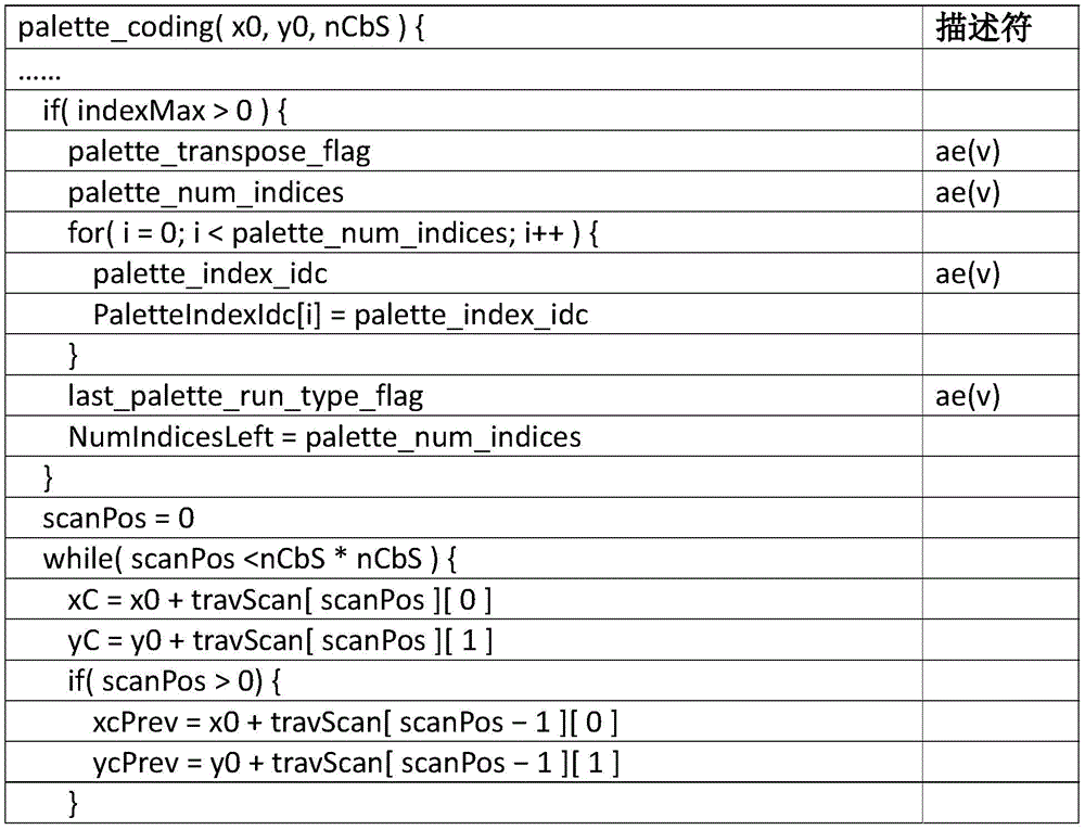
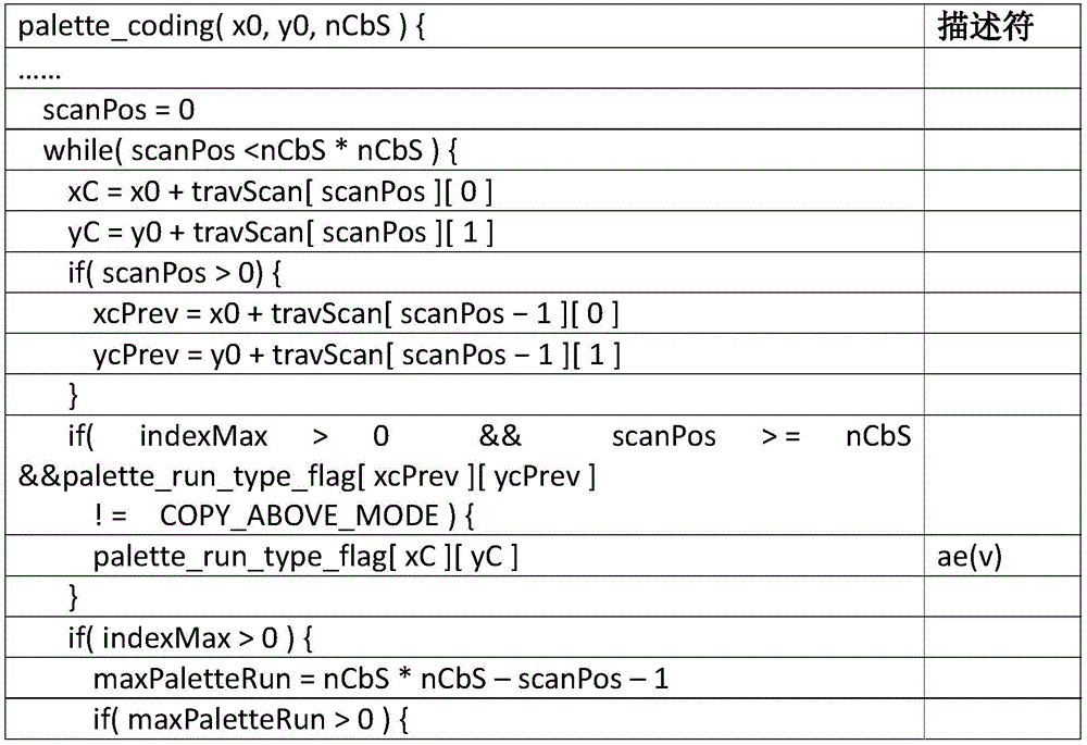
The syntax elements may be binarized to a binary string, where bypass bins and context-coded bins may be separately encoded by a Binary Arithmetic Coding (BAC) engine, e.g., context-based binary arithmetic coding (CABAC) for palette modes and other coding modes in HEVC screen image coding extensions. For two-level evaluation of context coding, a context model (e.g., a probability model) may be maintained for BAC in encoding and decoding. For bypass binary values, the syntax element may not be encoded under the context model. Grouping bypass bins together into longer chains may increase the number of bins processed per cycle (e.g., parsing throughput), which may be used to encode syntax elements in multiple HEVC, e.g., motion vector coding and coefficient coding. Palette index coded syntax elements (e.g., palette _ index _ idc) may be bypass coded and/or interleaved with other context coded syntax elements, e.g., palette _ run _ type and palette _ run _ msb _ id _ plus1, e.g., for palette design in HEVC screen content coding. The parsing of the palette _ index _ idc may be grouped together and placed before other context coded syntax elements, e.g., to improve parsing throughput. Table 2 is a syntax table for such palette coding.
Table 2: examples of palette syntax

The syntax element num _ palette _ index may specify the number of palette indices signaled in the current block. The syntax element palette _ last _ run _ type _ flag may specify the palette coding mode last run in the current block.
Although one or more embodiments described herein may be written using the video coding standard underlying the HEVC standard, embodiments may be applied to other video codecs.
Palette coding efficiency may be provided. Palette coding may encode horizontal and/or vertical lines. In the case of horizontal lines, the index mode may encode consecutive pixels using a run value (e.g., a large run value). If vertical, the vertical line may be considered a horizontal line in the vertical traversal scan order, e.g., as shown in FIG. 11B. Multiple directional lines may be applied in the screen content. FIG. 6 is a diagram showing an example SCC test sequence for a console.
Lines that are not in either the horizontal or vertical direction may be considered irregular lines. The block may be divided into a plurality of discrete segments, for example, if there are a plurality of irregular lines. It may be difficult to encode multiple discontinuous segments in an efficient way using the existing palette coding mode. Fig. 7A is a diagram showing an exemplary 8-color block having 4 colors, in which a dotted line shows a scanning order in palette coding. Fig. 7B shows a diagram of an exemplary 8-color block having 4 colors, where the dotted lines show the scanning order in palette coding using index mode and copy mode. For example, there may be two irregular lines in an 8 tile, for example, as shown in FIG. 7A. There may be four colors, white, gray, blue and yellow, which are indicated in fig. 7A and 7B by different dashed lines and/or shading. Fig. 7B illustrates an example of palette coding with run and copy modes in a horizontal traversal scan order for an 8x8 block. In general, 17 runs can be encoded with an index pattern as shown by the black dashed line and a copy pattern as shown by the black solid line.
A resolution dependency of palette coding may be provided. For example, given the high coding efficiency of palette coding for screen content, there may be a large percentage of CUs that select palette coding as the preferred coding mode, and thus, palette coding may limit data parsing dependencies to enable high throughput implementations. There may be a number of different kinds of dependencies in the palette coding design. For example, a context modeling dependency may be used, which may refer to a dependency on a previously encoded syntax element in a context fetch of one syntax element. Syntax parsing dependencies may be used, which may refer to dependencies in which the decoded value of one syntax element at a pixel position is used as an input for the parsing of the syntax element for a subsequent pixel position. Syntax signaling dependencies may be used, which may refer to dependencies that the signaling of one syntax element may depend on the decoded values of other syntax elements.
Context modeling dependencies may be provided. Context modeling dependencies of palette _ transpose _ flag may be provided. The horizontal traversal scan and/or the vertical traversal scan may be enabled to scan palette indices of a palette coded CU. Each CU that may encode a palette mode may signal a flag palette _ transpose _ flag to select one of the two scanning modes for the current CU. Two context models may be used for coding the flag palette _ transpose _ flag, which may be selected depending on whether the palette index of the left-neighboring CU of the current CU is scanned horizontally or vertically. Neighbor-based context modeling may provide greater coding efficiency. Neighbor-based context modeling may not allow a high degree of parallelism because two adjacent palette-coded CUs may not be decoded at the same time. The neighbor-based context modeling approach may use an additional buffer to store the state of palette _ transpose _ flag for the left-neighboring CU.
Context modeling dependencies for palette _ mode may be provided. A flag palette _ mode may be signaled for one or more pixel locations, e.g., except for pixel locations in the first row of a palette-coded CU (e.g., when no upper pixels are used for copying, the copy mode may be invalid for pixel locations in the first row). Two context models may be used to encode the palette _ mode flag, which may be determined based on the values of the same syntax elements for pixels juxtaposed in the upper line. Since the determination of the context at a pixel may depend on the palette index coding mode of the pixel preceding the pixel in scan order, the context modeling dependent term approach of palette _ mode may reduce throughput.
Dependencies related to escape color signaling may be provided. Syntax parsing dependencies for palette _ index may be provided. For pixels encoded in index mode, the palette index for the first pixel in the run-length chain may be signaled via the syntax element palette _ index. The syntax element palette _ index may be binarized using TBC because the maximum value of the palette index (e.g., pMax) is used as an input to the TBC process. The calculation of the TBC process input pMax to one pixel position may depend on whether the left-neighbor of the current pixel position and the CPI position are encoded as escape colors, e.g., since a redundancy removal method may be applied to palette index encoding and palette indices used to indicate escape colors may not be encoded in index mode or copy mode. For example, if the left-adjacent or CPI position of the current pixel position is encoded as the escape color, pMax can be set to the palette table Size of the current CU [ (Size) [ (PLT). Otherwise (e.g., if the left-neighbor of the current pixel position and the CPI position are both dominant colors), pMax can be set to Size, PLT-1. According to escape color signaling in the current palette coding design, an escape color may be identified by checking whether the decoded palette index at one pixel position is equal to the palette table size. Thus, the decoded value of the current palette _ index syntax element may determine the value of the next syntax element to be processed. A palette index may be decoded after the palette index at its CPI position is fully reconstructed, for example, when a redundancy removal method is used in palette index coding.
Syntax signaling dependencies for palette _ escape _ val may be provided. For an escape color location (e.g., each escape color location of a CU), the color values of the location may be quantized (e.g., if lossy coding is used) and transmitted to a decoder. For example, the escape color may be represented in a bitstream by signaling a syntax element palette _ index (e.g., when the redundancy removal scheme is not used, palette _ index equals { Size }', PLT-1 when the redundancy removal scheme is used), followed by another syntax element palette _ escape _ val, which may indicate quantized color values (e.g., if lossy coding is used). When a pixel is recognized as an escape color as indicated by the palette _ index, the syntax palette _ escape _ val element may be signaled (e.g., signaled only). Thus, the value of the palette _ index syntax element may determine what syntax element is to be processed. For example, if the palette _ index indicates that the current pixel is an escape color, the next syntax element may be palette _ escape _ val, otherwise the next syntax element may be palette _ run. Based on the same analysis of the syntax parsing dependencies of the palette _ index, after the palette index of the CPI position is fully reconstructed, one pixel may be (e.g., may only be) identified as an escape color, e.g., due to the redundancy removal process applied to the palette index encoding. Thus, escape color syntax signaling dependencies can cause throughput problems.
Syntax signaling dependencies for palette _ run may be provided. The syntax element palette _ run may indicate the number of consecutive pixels in index mode and copy mode that have the same palette index. When a pixel is identified as a dominant color, signaling of the syntax element palette _ run may be signaled (e.g., signaled only), for example, in contrast to palette _ escape _ val. Therefore, a similar syntax signaling dependency problem that can be used for the element palette _ escape _ val can exist in the signaling of palette _ run.
Palette table generation (e.g., only on the encoder side) may be provided. A color aggregation-based palette table generation method may be used to select a dominant color of a CU encoded using a palette mode by aggregating color values of the current CU into a plurality of sets and using a centroid (centroid) of a color cluster as the dominant color in the palette table. In lossy coding, a color cluster may be generated by quantizing pixels, since the distortion between the color value and the centroid of the cluster may be a predefined threshold for the same dominant color. The threshold may be set based on the assumption that the bit depth of the luminance and chrominance components is equal to 8 bits. Therefore, the current palette table generation method may not be suitable for handling the case when the bit depth of the input screen content view is greater than 8 bits.
One or more embodiments may handle the conflict of merging of extended copy mode and packed palette indices ahead. For example, the palette index encoding binary value may be grouped before one palette CU. The palette index (as specified by the syntax element palette _ index _ idc) may be binarized by TBC coding requiring knowledge of the maximum possible level. Redundancy removal may not be applied to pixels whose CPI pixels refer to NCP. Thus, different maximum TBC levels may be obtained depending on the pixel location. For example, for pixels that involve CPI pixels associated with NCPs from neighboring CUs, the maximum TBC level pMax may remain unchanged (e.g., the size of the palette table is reduced by one when there are no escape color pixels in the current CU, or the size of the palette table when there is at least one escape color pixel in the current CU). For pixels that involve CPI pixels that are not associated with NCPs from neighboring CUs, the maximum TBC level pMax may be reduced by one. The parsing of the syntax palette _ index _ idc for one pixel may depend on the knowledge of the palette coding mode of the previous pixel in palette scan order. And, this knowledge may be obtained after decoding the palette coding mode (e.g., palette _ run _ type _ flag) and palette run (e.g., palette _ run _ msb _ id _ plus1 and palette _ run _ refinement _ bits) for pixels before the current pixel. Thus, when extended copy mode is enabled, the parsing of the grouped palette indices may not be preceded by the parsing of the palette mode and palette run.
For example, in order to group palette indices at the beginning of the palette parsing process simultaneously with enabling the above extended copy, the palette signaling method may reduce the maximum TBC level pMax by one. The dynamic range of palette indices for those pixels may be from 0 to pMax, e.g., pixels whose CPI pixels refer to NCPs from neighboring CUs because of redundancy removal may not be applied to them. For example, to compensate for the reduced dynamic range of palette indices, an additional flag may be signaled for those pixels (e.g., whose CPI pixels refer to pixels of the NCP from neighboring CUs) when the corresponding parsed palette index is equal to pMax-1. If the flag is equal to 1, the palette index may be decoded to pMax. If the flag is equal to 0, the palette index may be decoded to pMax-1. For example, table 3 is a palette syntax table example.
Table 3: palette syntax table example


One or more embodiments may address the unknown TBC maximum problem in the front when merging the packet index with an extended copy-above (copy-above) pattern. The syntax element palette _ index _ refinement _ flag may be coded as a bypass binary value and/or interleaved with the syntax elements of the context coded signaling palette mode and palette run. To parse the value of palette _ index _ refinement _ flag, the decoder may check whether the current pixel has one CPI position referring to the pixel from the neighboring CU and/or whether the palette index previously parsed is equal to pMax-1.
An encoding mode sketch copy mode is proposed to encode blocks containing irregular lines. Syntax redundancy can be removed from blocks with special characteristics. Run value encoding can be simplified. The resolution dependencies in current palette coding designs may be removed. For example, context modeling dependencies of the syntax element palette _ transpose _ flag may be removed, e.g., by simplifying the corresponding context model. The context modeling of the syntax element palette _ mode can be removed, for example, by using run-length coding without using context. Syntax parsing dependencies and/or syntax signaling dependencies related to escape color signaling may be removed. The palette table generation process may use a high bit depth to process the input screen content video, e.g., at the decoder side.
A sketch copy mode for palette coding may be provided. The sketch copy mode may be performed by copying palette indices from coded neighbor sample positions in one or more directions (e.g., diagonal (diagonals), horizontal direction, and/or vertical direction, which may include any classification). The sketch copy mode may allow for copying of pixels in one or more particular directions. The encoded irregular lines (e.g., diagonal) may be considered during running the count. One or more (e.g., three) syntax elements may be encoded for the sketch mode: color index, direction, and/or run. The color index may be an index into the palette table and/or equal to the size of the palette table indicating the escape color. The direction information may be encoded along with the color index. The running value may be encoded to indicate the number of pixels having the same color index as the first pixel in the signaling direction.
The direction of encoding can be defined. Fig. 8A is a diagram showing an example of 16 directions with coarse granularity. Fig. 8B is a diagram showing an example of 16 directions with fine granularity. Fig. 8A and 8B show the definition of 16 directions at different granularities, where each side edge can have 8 directions, respectively. The orientation in FIG. 8A may be defined by the following equation:
θi=tan-1(xi),xi={1,2,...,8}
the direction defined in fig. 8B may be at fine granularity, and the direction may be defined by the following formula:
θi=tan-1(xi),xi={1/2,1,...,4}
the vertical direction may not be considered in the sketch copy mode, for example, because the indexing mode in a vertical traversal scan may effectively encode vertical lines. The number of directions can be reduced if the overhead for directional coding affects the performance, e.g. in case of low bit rate coding. The direction information may be divided into one or more elements, for example, an index of a direction at one side and a flag "is _ right _ flag". "is _ right _ flag" can be used to indicate to which side the direction belongs. The maximum index of directions may be equal to a number of different directions, e.g., seven different directions (e.g., for each edge) as in the example given in fig. 8A and 8B. The direction of previously encoded neighbor pixels may be considered, for example, to further remove redundancy of direction encoding. The flag "same _ direction _ flag" may be encoded if the current pixel has the same direction as compared to the direction of the previously encoded neighbor pixels (e.g., only the flag "same _ direction _ flag" is encoded). If the direction is different but has the same value as "is _ right _ flag", the clipping process may be performed. FIG. 9 is an example flow diagram illustrating a directional encoding algorithm for a sketch copy mode.
Fig. 10 is a diagram showing an example of palette coding using a sketch copy mode. Fig. 10 may be compared to the palette coding in fig. 7B. Irregular lines may be encoded using a sketch pattern. At position S11, an irregular line (e.g., the diagonal from S11 to S39) may be encoded by the sketch pattern having a run value equal to 3. The is _ right _ flag may be set to 1 and the direction index may be 0. At position S12, an irregular line (e.g., the diagonal from S12 to S32) may be encoded by the sketch pattern having a run value equal to 3. The is _ right _ flag may be set to 0 and the direction index may be 0. After position S12, the index pattern may encode the pixels remaining in the block. A total of five runs may be encoded, for example, because no irregular lines are included. The number of segments in the block may be reduced by enabling the sketch copy mode.
A block for which palette coding is intended may comprise a plurality of colors. The sketch copy mode may be applied (e.g., only applied) to a block that includes one or more irregular lines. If there are no irregular lines within a block, the sketch copy mode may not be selected, although, for example, the mode may be enabled. As one or more additional modes are added, the signaling overhead for run and copy modes may be increased. Thus, the use of sketch copy mode may be limited to reduce signaling overhead. A flag may be added to the palette coded coding unit to indicate whether the sketch copy mode is enabled. For example, if not enabled, no signaling overhead is increased. The application of the sketch copy mode may be limited, for example, the sketch copy mode may be used within a block, since the sketch copy mode will not save much if there are not so many pixels remaining. The sketch copy mode may not save signaling overhead for the remaining pixel encodings, e.g., if the encoding position is outside a particular row defined by a threshold. The threshold may be adapted to the size of the coding unit. For example, for 8x8, 16x16, 32x32, and/or 64x64 coding units, the threshold may be [4,7,12,16 ].
The scanning method can be extended. Fig. 11A and 11B show examples of encoding orders of the horizontal traversal scan and the vertical traversal scan, respectively. The horizontal traversal scan and/or the vertical traversal scan may be performed in a reverse order, which may correspond to rotating the block 180 degrees in a clockwise manner or 180 degrees in a counterclockwise manner, for example. Fig. 11C and 11D show examples of the encoding order of the reverse horizontal traversal scan and the reverse vertical traversal scan, respectively.
Redundancy removal for palette table syntax elements may be provided. The syntax element palette _ escape _ val _ present _ flag may be used to indicate whether an escape color is present in a Coding Unit (CU). The escape color may be signaled with a color index equal to the palette table size. If there are no escape colors, the maximum color index may be equal to the palette table size minus one. Otherwise, the maximum color index may be equal to the palette table size. The maximum value may affect color index coding, e.g., since color indices may be coded using truncated two-level coding. The number of bits for variable x in truncated bi-level coding can be provided by:

where M is the maximum value of the variable x plus one. From the above equation, it can be determined that the additional value can be encoded by (n-1) bits having smaller M. The element palette _ escape _ val _ present _ flag may not be signaled, e.g., to remove palette signaling redundancy. When the palette table size of the CU is 0 (e.g., the palette table is empty), the decoder may determine that all pixels are escape colors (e.g., there is no dominant color in the palette table). Therefore, when the palette table size of the CU is 0, palette _ escape _ val _ present _ flag may not be signaled and the decoder may conclude that the value is 1. When the palette table size is a value other than 0, then palette _ escape _ val _ present _ flag may be signaled. Therefore, when the palette table size is a value other than 0, the palette _ escape _ val _ present _ flag may be signaled (e.g., only notified). If there is one color (e.g., only one color) in the coding unit (e.g., palette table size is 1 and palette _ escape _ val _ present _ flag is 0) or if all pixels are coded as escape colors (e.g., palette table size is 0 and palette _ escape _ val _ present _ flag is 1), the palette mode may be in the index mode (e.g., inferred to be in the index mode (e.g., run mode)) and the run value may be the size of the coding unit minus 1 if the run is coded. For example, if there is one color (e.g., only one color) in the coding unit (e.g., palette table size is 1 and palette _ escape _ val _ present _ flag is 0), the decoder may not receive palette _ mode and/or may infer palette _ mode to be equal to 0 (e.g., infer to be in index mode (e.g., run mode)) and/or may not receive palette _ run and/or may infer palette _ run to be equal to CU size minus 1. The conditions for adding palette mode signaling and/or run coding are shown in table 6.
Entropy coding of the syntax element Run in palette coding may be provided. Two different encodings can be used to encode the syntax element Run. Table 4 is an example of Run value binarization. There may be three segments for the entire Run range, the first, second, and third bits of the binary may be context coded (as shown in bold in table 4), and the subsequent bits in the binary may be bypass coded without any context (as shown in non-bold in table 4). 0 through 2 may be the first segment of the fixed context coding for each bin. 3-26 may be the second segment. The prefix may be encoded the same as segment 1, the suffix may be encoded by a Golomb-Rice code and/or the ear (Rice) parameter may be equal to 3. A value exceeding 26 may be the third segment. The prefix of the third segment may be encoded as in segment 1. The suffix may be encoded by an Exp-Golomb code. From a run value of 3 to 10, 3 prefix binary codes and/or 4 suffix binary codes may be encoded. The second order Exp-Golomb may be provided to values exceeding 2. Exemplary binarization may be provided in table 5. For small runs, the number of binary codes can be reduced.
TABLE 4 exemplary binarization of Run values (e.g., in SCC)

Table 5: exemplary binarization of Run values


Resolution dependent term improvements of palette coding may be provided. Context modeling dependencies that remove the syntax element "palette _ transpose _ flag" may be provided. One or more (e.g., two context models) may be used to encode the syntax element palette _ transpose _ flag. For example, a context model is selected for palette _ transpose _ flag based on whether the palette index of the left-neighboring CU of the current CU is scanned horizontally or vertically. The parallel design of the actual implementation may be complicated because the bitstreams of two neighboring palette-coded CUs may not be parsed simultaneously. This neighbor-based context modeling may use a binary buffer to store the values of the syntax elements of the left-neighboring CUs. For example, when other CU-level flags (e.g., such as palette _ share _ flag, palette _ escape _ val _ present _ flag, num _ signaled _ palette _ entries, etc.) may be encoded in bypass mode and/or context mode using a single context, the palette _ transit _ flag may be a CU-level flag whose context model is built using its spatial neighbors.
The context modeling dependency on the syntax element palette _ transpose _ flag on the left-hand side of the current CU may be removed, e.g., by using a single context coding flag. This may be performed to improve parallelism capability and/or to make palette coded CU level signaling design more consistent.
The syntax element palette _ transpose _ flag may be encoded in bypass mode.
The context modeling dependency of the syntax element "palette _ mode" may be removed. One or more context models may be used to encode palette _ mode flags, which may be determined based on the values of the same syntax elements for the parallel pixels in the upper line. Table 6 shows an example of context modeling for encoding the palette _ mode flag. In index mode and/or copy mode, palette _ mode may be decoded for each run-length chain of consecutive pixels having the same palette index. Accordingly, the context modeling method may reduce the throughput of the parsing process when the determination of the context on one pixel may depend on the palette index coding mode of the pixel preceding it in the scan sequence.
Table 6: example of context modeling of syntax element palette _ mode

The flag palette _ mode of one CU may form a binary vector including elements 0 or 1. Run Length Encoding (RLE) is a method of encoding a binary vector by indicating the number of consecutive 0 s between two 1 s. RLE may be used for applications requiring high throughput, e.g., because multiple binary codes may be generated together in a single cycle. For example, to remove the context modeling of palette _ mode, RLE may be used to encode the syntax element palette _ mode.
The syntax element palette _ mode context modeling dependency can be removed by using a single context coding flag.
Syntax parsing and/or signaling dependencies related to escape color signaling may be removed. For example, due to TBC-based binarization and redundancy removal algorithms used for palette index coding, there may be syntax parsing dependencies and syntax signaling dependencies associated with escape colors when parsing syntax elements palette _ index, palette _ escape _ val, and palette _ run. For example, resolution dependencies may be removed for higher throughput and/or improved efficiency of palette coding.
For example, while current palette coding methods may use the largest palette index to indicate an escape color, the palette index for the escape color may not be coded in index mode or copy mode. For example, when an escape color is encountered, one run-length chain of consecutive pixels with the same palette index may be broken. This may yield to the overall coding efficiency of palette coding and/or introduce dependency terms to the parsing process of a CU encoded using palette mode. After applying the redundancy removal algorithm, the palette index of a pixel may be parsed after the palette index of its CPI position is fully reconstructed (e.g., to check whether the CPI position is encoded as an escape color, which may determine the input parameter pMax of the TBC binarization process).
The palette index for indicating escape colors may be used as one normal palette index and may be encoded using an index mode and/or a copy mode. For example, the decoder may parse the palette index run value for the CU. The palette index run value may indicate a length of consecutive palette indices for the corresponding pixel position in the CU. One or more palette indices may correspond to escape colors. For example, the palette index may correspond to a plurality of different escape color values. Thus, runs of escape colors (e.g., which may be the same or different escape colors) may be encoded in the index mode and/or the copy mode. For example, color values for different pixel locations of a CU may be encoded according to one or more runs, which may include one or more runs of a dominant color and/or one or more runs of an escape color. The run of escape colors may be the same escape color or runs of different escape colors. The decoder may reconstruct consecutive palette indices for the corresponding pixel positions of the CU from the palette index run value (e.g., may be a run of escape colors). The decoder may reconstruct the color value for the CU pixel location from the palette index and/or the one or more palette _ escape _ val values. For example, in order to remove syntax signaling dependencies of the element palette _ escape _ val, parsing of the syntax element palette _ escape _ val may be separated from parsing of other syntax elements. For example, one or more scan channels may be applied to parse syntax elements of a palette-coded CU. The scan channel (e.g., the first scan channel) may parse existing palette syntax elements other than palette _ escape _ val. Scan channels (e.g., the second scan channel), for example, may parse the syntax element palette _ escape _ val based on the decoded palette index from the first scan channel. In the second scanning pass, when the palette index of one pixel position (as obtained by the first pass) is equal to the palette table size of the current CU (e.g., escape color), the palette _ escape _ val may be parsed for one pixel position.
Syntax parsing dependencies of palette indices may be removed. The maximum palette index pMax may use a fixed value (e.g., the maximum value of the palette table size) as an input to the TBC binarization process for palette index coding. In order to remove syntax signaling dependencies on the elements palette _ escape _ val and palette _ run of the escape color, a redundancy removal method for the escape color may be removed.
Improved palette table generation for high bit depths may be provided. A color aggregation-based palette table generation method may be used to select a dominant color of a palette mode encoded CU by aggregating color values of the current CU into multiple sets and using a centroid of a color cluster as the dominant color in the palette table. In lossy coding, a color cluster may be generated by quantizing pixels (e.g., all pixels), for which the distortion between the color value and the centroid of the cluster is less than a predefined threshold T for the same dominant color, e.g., as shown in the following equation:

where P _ i and C _ i may represent the value of the ith component of the centroid of the current pixel and cluster, respectively. The threshold T may be set depending on the quantization parameter. Table 7 shows an example of mapping between the value of T and the quantization parameter.
Table 7: example of mapping between Quantization Parameter (QP) and threshold T (as in SCM-2.0)
| QP | 0 | 1 | 2 | 3 | 4 | 5 | 6 | 7 | 8 | 9 | 10 | 11 | 12 |
| T | 0 | 0 | 0 | 0 | 1 | 1 | 1 | 2 | 2 | 2 | 3 | 3 | 3 |
| QP | 13 | 14 | 15 | 16 | 17 | 18 | 19 | 20 | 21 | 22 | 23 | 24 | 25 |
| |
4 | 4 | 4 | 5 | 5 | 5 | 6 | 6 | 7 | 7 | 8 | 9 | 9 |
| |
26 | 27 | 28 | 29 | 30 | 31 | 32 | 33 | 34 | 35 | 36 | 37 | 38 |
| |
10 | 11 | 12 | 13 | 14 | 15 | 16 | 17 | 19 | 21 | 22 | 24 | 23 |
| |
39 | 40 | 41 | 42 | 43 | 44 | 45 | 46 | 47 | 48 | 49 | 50 | 52 |
| |
25 | 26 | 28 | 29 | 31 | 32 | 34 | 36 | 37 | 39 | 41 | 42 | 45 |
In table 7, the value of the threshold T may be determined assuming that the input bit depth of the luminance and chrominance components is 8 bits. Thus, the palette table by the current palette table generation method may not be suitable for handling a case where the bit depth of the input screen content video is more than 8 bits. To improve the coding efficiency of palette coding at high bit depths, 8-bit distortion may be used for the palette table generation process. The bit depths of luminance and chrominance components can be expressed as "BitDepth" s and "BitDepth" s, and the distortion calculation formula can be as follows:

table 8 illustrates an example of a syntax that may be used to enable the syntax redundancy removal methods described herein and/or remove the parsing dependencies described herein.
Table 8: examples of palette coding syntax


One or more embodiments may include extending the parsing throughput of the coding mode. For example, when extended copy mode is enabled, parsing of the grouped palette indices may not be placed before parsing of the palette mode and palette run. One or more embodiments to increase parsing throughput may be provided that may be applied jointly with an extended copy mode.
Palette indices may be grouped together and placed after palette mode and run (e.g., as opposed to placing indices before mode and run). Escape colors may be separated and placed after the palette indices. For example, a subsequent palette syntax arrangement may be used. Syntax elements related to palette mode and palette run (e.g., may include palette _ run _ type _ flag, palette _ run _ msb _ id _ plus1, palette _ run _ refinement _ bits, etc.) may be placed in the current CU (e.g., first in the current CU). One or more (e.g., all) palette indices (e.g., palette _ index _ idc) for one or more (e.g., all) pixels encoded by the index pattern may be placed after the syntax elements associated with the palette pattern and palette run. One or more escape colors (e.g., all) of one or more (e.g., all) pixels encoded as escape colors may be placed after the palette index of the pixel. Table 9 shows an example of a palette syntax table having such an arrangement.
Table 9: palette coding syntax example

The palette run may be encoded by the HEVC SCC run encoding method. One or more of the operational encoding methods described herein may be combined with one or more of the described embodiments. For example, table 10 is an example of a palette syntax containing run-to-end (run-to-end) encoding with the arrangement described previously.
Table 10: palette coding syntax example


Syntax elements for palette index coding (e.g., palette _ index _ idc) and escape color (e.g., palette _ escape _ val) may be grouped separately, e.g., in the exemplary palette coding syntax of table 10. In this embodiment, two separate scan cycles may be used for the palette index and escape color value in the current CU.
One or more embodiments may group the palette indices and escape colors together (e.g., within a group, palette _ index _ idc and palette _ escape _ val are still interleaved) and place them after, for example, palette mode and palette run. Both the palette _ index _ idc and palette _ escape _ val may be bypass-coded. For example, the following syntax element arrangement may be provided: syntax elements related to the palette mode and palette run (e.g., palette _ run _ type _ flag, palette _ run _ msb _ plus1, and/or palette _ run _ redefinition _ bits) are set first in the current CU, and one or more (e.g., all) syntax elements (e.g., palette _ index _ idc and palette _ escape _ val) are grouped together and placed after the palette mode and palette run, examples of which are provided in table 11.
Table 11: palette coding syntax example


A second run encoding method may be used. For example, table 12 is an example of a palette syntax table with the above arrangement that contains a second run encoding (e.g., run-to-end syntax element).
Table 12: palette coding syntax example

If palette indices are grouped before palette mode, palette run, and escape colors, and extended copy above mode is enabled, the maximum value for palette index coding in the TBC may be uncertain for those palette indices whose above neighbor pixels refer to pixels of neighbor CUs. The index at the upper neighbor position may not be available. When the encoded value is equal to the maximum value (e.g., index _ max) minus one, an additional flag may be signaled to indicate whether the encoded value should be interpreted as a maximum value minus one or as a maximum value.
One or more embodiments may be provided in which palette indices are grouped (e.g., arranged) in a front and extended copy above mode is enabled. A CU level indication (e.g., flag) may be provided. For example, the CU level indication may be prearranged to indicate how the decoder interprets and/or entropy encodes the palette indices.
The syntax element use _ index _ max _ for _ palette _ indices may be sent as a CU level flag, for example, as shown in table 13. If the use _ index _ max _ for _ palette _ indices flag has a value of 1, the palette index may be encoded using a maximum value of TBC equal to the palette table size if there is no escape color, or may be encoded using a maximum value of TBC equal to the palette table size plus one if there is an escape color. If the use _ index _ max _ for _ palette _ indices flag has a value of 0, the palette index may be encoded using a maximum value of TBC equal to the palette table size minus one if there is no escape color, or may be encoded using a maximum value of TBC equal to the palette table size if there is an escape color. The decoder may determine the maximum value of the TBC and decode the palette index accordingly.
Table 13: palette coding syntax example


The syntax element use _ index _ max _ for _ palette _ indices may indicate whether index _ max is a maximum value of TBC coding as a palette index. The syntax element use _ index _ max _ for _ palette _ indices having a value of 1 may indicate that the coding of the palette index uses a maximum value of TBC equal to the palette table size if there is no escape color, or indicate that the coding of the palette index uses a maximum value of TBC equal to the palette table size plus one if there is an escape color. The syntax element use _ index _ max _ for _ palette _ indices having a value of 0 may indicate that the coding of the palette index uses a maximum value of TBC equal to the palette table size minus one if there is no escape color, or uses a maximum value of TBC equal to the palette table size if there is an escape color.
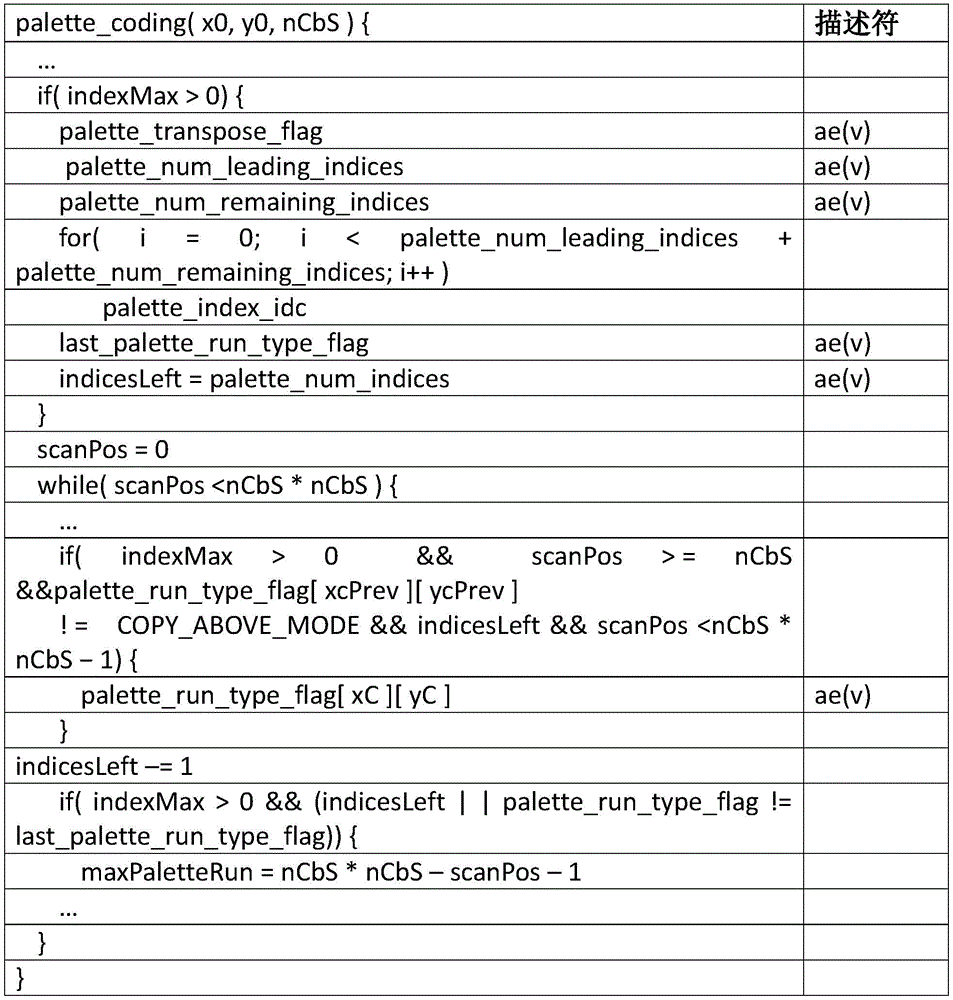
The syntax element use _ index _ max _ for _ palette _ indices may be used as a CU level flag, for example, as shown in table 14. If the syntax element use _ index _ max _ for _ palette _ indices has a value of 1, the number of leading (leading) palette indices may be encoded using the maximum value of TBC equal to the palette table size if there is no escape color, or the number of leading palette indices may be encoded using the maximum value of TBC equal to the palette table size plus one if there is an escape color. The number of remaining palette indices may be encoded using a maximum value of TBC equal to the palette table size minus one if there is no escape color, or may be encoded using a maximum value of TBC equal to the palette table size if there is an escape color. The number of dominant palette indices may be sent to the decoder as the value palette _ num _ leading _ indices. The number of palette indices remaining may be sent to the decoder as the value palette _ num _ remaining _ indices. The value of the palette _ num _ leading _ indices may be additionally sent conditionally, e.g., only if use _ index _ max _ for _ palette _ indices has a value of 1, the value of the palette _ num _ leading _ indices is sent in the bitstream.
If the syntax element use _ index _ max _ for _ palette _ indices has a value of 0, the value of palette _ num _ leading _ indices may not be present in the form of a bitstream and may be inferred to have a value of 0. In this case, one or more (e.g., all) palette indices may be encoded using the maximum value of TBC equal to the palette table size minus one if there is no escape color, or one or more (e.g., all) palette indices may be encoded using the maximum value of TBC equal to the palette table size if there is an escape color. The decoder may use these syntax elements to determine the maximum value of TBC for one or more (e.g., each) palette indices, and may decode the palette indices accordingly.
Table 14: examples of palette syntax

The syntax element use _ index _ max _ for _ palette _ indices may indicate whether a non-zero value for palette _ num _ leading _ indices is signaled in the bitstream. The syntax element palette _ num _ leading _ indices may indicate the number of leading palette indices coded by the maximum value of TBC coding set to the palette table size if there is no escape color coding in the current CU, or set to the palette table size plus one if there is escape color coding in the current CU. If not present, the value of palette _ num _ leading _ indices may be inferred to be 0. The syntax element palette _ num _ remaining _ indices may be indicative of the number of palette indices coded by the TBC coded maximum value set to the palette table size minus one in case of no escape color coding in the current CU or to the palette table size in case of escape color coding in the current CU.
In the case where use _ index _ max _ for _ palette _ indices are not signaled and/or are rendered (e.g., always rendered), palette indices may be provided, e.g., as shown in table 15.
Table 15: examples of palette syntax
The signaling of palette _ index _ refinement _ flag may be moved from a parse cycle of palette mode and palette run to a parse cycle of palette indices. The maximum TBC pricing may be decremented by one (e.g., pMax-1) before parsing the palette indices of a palette coded CU. When the resolved palette index of one pixel is equal to pMax-1, palette _ index _ refinement _ flag may be signaled (e.g., always signaled). Such syntax may include higher parsing throughput, for example, because the palette index coded bypass binaries may be separated from the palette mode and palette run context coded binaries. Table 16 provides an example of this syntax.
Table 16: examples of palette syntax

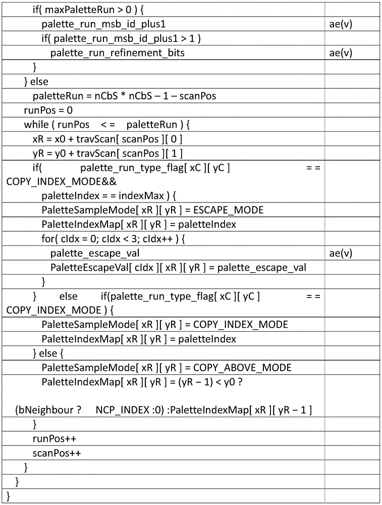
Fig. 14A is a diagram of an example communication system 100 in which one or more disclosed embodiments may be implemented. The communication system 100 may be a multiple-access system that provides content, such as voice, data, video, messaging, broadcast, etc., to a plurality of wireless users. The communication system 100 allows multiple wireless users to access such content by sharing system resources, including wireless bandwidth, for example, the communication system 100 may use one or more channel access methods, such as Code Division Multiple Access (CDMA), Time Division Multiple Access (TDMA), Frequency Division Multiple Access (FDMA), orthogonal FDMA (ofdma), single-carrier FDMA (SC-FDMA), and so on.
As shown in fig. 14A, the communication system 100 may include wireless transmit/receive units (WTRUs) 102a, 102b, 102c, and/or 102d (generally or collectively referred to as WTRUs 102), a Radio Access Network (RAN)104, a core network 106/107/109, a Public Switched Telephone Network (PSTN)108, the internet 110, and other networks 112, although it should be appreciated that the disclosed embodiments contemplate any number of WTRUs, base stations, networks, and/or network components. Each WTRU102a, 102b, 102c, 102d may be any type of device configured to operate and/or communicate in a wireless environment. For example, the WTRUs 102a, 102b, 102c, 102d may be configured to transmit and/or receive wireless signals and may include User Equipment (UE), a mobile station, a fixed or mobile subscriber unit, a pager, a cellular telephone, a Personal Digital Assistant (PDA), a smartphone, a laptop, a netbook, a personal computer, a wireless sensor, a consumer electronics device, and the like.
The base station 114a may be part of a RAN103/104/105, which may also include other base stations and/or network components (not shown), such as Base Station Controllers (BSCs), Radio Network Controllers (RNCs), relay nodes, and so forth. Base station 114a and/or base station 114b may be configured to transmit and/or receive wireless signals within a particular geographic area known as a cell (not shown). The cell may be further divided into cell sectors. For example, the cell associated with base station 114a may be divided into three sectors. Thus, in one embodiment, the base station 114a may include three transceivers, that is, each transceiver corresponds to a sector of a cell. In another embodiment, the base station 114a may use multiple-input multiple-output (MIMO) technology, whereby multiple transceivers may be used for each sector of the cell.
The base stations 114a, 114b may communicate with one or more WTRUs 102a, 102b, 102c, 102d via an air interface 115/116/117, which air interface 115/116/117 may be any suitable wireless communication link (e.g., Radio Frequency (RF), microwave, Infrared (IR), Ultraviolet (UV), visible light, etc.). The air interface 115/116/117 may be established using any suitable Radio Access Technology (RAT).
More specifically, as described above, communication system 100 may be a multiple-access system and may use one or more channel access schemes, such as CDMA, TDMA, FDMA, OFDMA, SC-FDMA, and the like. For example, the base station 114a and WTRUs 102a, 102b, 102c in the RAN103/104/105 may implement a radio technology such as Universal Mobile Telecommunications System (UMTS) terrestrial radio access (UTRA), and the technology may establish the air interface 115/116/117 using wideband cdma (wcdma). WCDMA may include communication protocols such as High Speed Packet Access (HSPA) and/or evolved HSPA (HSPA +). HSPA may include High Speed Downlink Packet Access (HSDPA) and/or High Speed Uplink Packet Access (HSUPA).
In another embodiment, the base station 114a and the WTRUs 102a, 102b, 102c may implement a radio technology such as evolved UMTS terrestrial radio access (E-UTRA) that may establish the air interface 115/116/117 using Long Term Evolution (LTE) and/or LTE-advanced (LTE-a).
In other embodiments, the base station 114a and the WTRUs 102a, 102b, 102c may implement radio access technologies such as IEEE802.16 (worldwide interoperability for microwave Access (WiMAX)), CDMA2000, CDMA 20001X, CDMA2000EV-DO, Interim Standard 2000(IS-2000), Interim Standard 95(IS-95), Interim Standard 856(IS-856), Global System for Mobile communications (GSM), for enhanced data rates for GSM evolution (EDGE), GSM EDGE (GERAN), and so forth.
By way of example, the base station 114B in fig. 14A may be a wireless router, home nodeb, home enodeb, or access point, and may facilitate wireless connectivity in a local area using any suitable RAT, such as a business, residence, vehicle, campus, and so forth. In one embodiment, the base station 114b and the WTRUs 102c, 102d may establish a Wireless Local Area Network (WLAN) by implementing a radio technology such as IEEE 802.11. In another embodiment, the base station 114b and the WTRUs 102c, 102d may establish a Wireless Personal Area Network (WPAN) by implementing a radio technology such as IEEE 802.15. In yet another embodiment, the base station 114b and the WTRUs 102c, 102d may establish the pico cell or the femto cell by using a cellular-based RAT (e.g., WCDMA, CDMA2000, GSM, LTE-a, etc.). As shown in fig. 14A, the base station 114b may be directly connected to the internet 110. Thus, the base station 114b does not necessarily need to access the internet 110 via the core network 106/107/109.
The RAN103/104/105 may be in communication with a core network 106/107/109, which may be any type of network configured to provide voice, data, applications, and/or voice over internet protocol (VoIP) services to one or more WTRUs 102a, 102b, 102c, 102 d. For example, the core network 106/107/109 may provide call control, billing services, mobile location-based services, pre-paid calling, internet connectivity, video distribution, etc., and/or perform high-level security functions such as user authentication. Although not shown in fig. 14A, it should be appreciated that the RAN103/104/105 and/or the core network 106/107/109 may communicate directly or indirectly with other RANs that employ the same RAT as the RAN103/104/105 or a different RAT. For example, in addition to interfacing with the RAN103/104/105 using E-UTRA radio technology, the core network 106/107/109 may also communicate with another RAN (not shown) using GSM radio technology.
The core network 106/107/109 may also serve as a gateway for the WTRUs 102a, 102b, 102c, 102d to access the PSTN108, the internet 110, and/or other networks 112. The PSTN108 may include a circuit-switched telephone network that provides Plain Old Telephone Service (POTS). The internet 110 may include a worldwide system of interconnected computer networks and devices that use common communication protocols, which may be the Transmission Control Protocol (TCP), User Datagram Protocol (UDP), and the Internet Protocol (IP) of the TCP/IP internet protocol suite. The network 112 may include wired or wireless communication networks owned and/or operated by other service providers. For example, the network 112 may include another core network connected to one or more RANs, which may employ the same RAT as the RAN103/104/105 or a different RAT.
Some or all of the WTRUs 102a, 102b, 102c, 102d in the communication system 100 may include multi-mode capabilities, i.e., the WTRUs 102a, 102b, 102c, 102d may include multiple transceivers that communicate with different wireless networks over different wireless links. For example, the WTRU102 c shown in figure 14A may be configured to communicate with a base station 114A that uses a cellular-based radio technology and with a base station 114b that may use an IEEE802 radio technology.
Figure 14B is a system diagram illustrating a WTRU 102. As shown in fig. 14B, the WTRU102 may include a processor 118, a transceiver 120, a transmit/receive component 122, a speaker/microphone 124, a keypad 126, a display/touchpad 128, non-removable memory 130, removable memory 132, a power source 134, a Global Positioning System (GPS) chipset 136, and other peripherals 138. It is to be appreciated that the WTRU102 may include any subcombination of the foregoing components while remaining consistent with an embodiment. Moreover, embodiments contemplate that base stations 114a and 114B, and/or the nodes that base stations 114a and 114B may represent, may include some or all of the elements depicted in fig. 14B and described herein, wherein nodes such as, but not limited to, transceivers (BTSs), node bs, site controllers, Access Points (APs), home node bs, evolved home node bs (enodebs), home evolved node bs (henbs), home evolved node B gateways, and proxy nodes, among others.
The processor 118 may be a general purpose processor, a special purpose processor, a conventional processor, a Digital Signal Processor (DSP), a plurality of microprocessors, one or more microprocessors in association with a DSP core, a controller, a microcontroller, Application Specific Integrated Circuits (ASICs), Field Programmable Gate Arrays (FPGAs) circuits, any other type of Integrated Circuit (IC), a state machine, or the like. The processor 118 may perform signal coding, data processing, power control, input/output processing, and/or any other functionality that enables the WTRU102 to operate in a wireless environment. The processor 118 may be coupled to a transceiver 120 and the transceiver 120 may be coupled to a transmit/receive component 122. Although fig. 14B depicts processor 118 and transceiver 120 as separate components, it should be understood that processor 118 and transceiver 120 may be integrated in one electronic package or chip.
The transmit/receive component 122 may be configured to transmit or receive signals to or from a base station (e.g., base station 114a) via the air interface 115/116/117. For example, in one embodiment, the transmit/receive component 122 may be an antenna configured to transmit and/or receive RF signals. In another embodiment, the transmit/receive component 122 may be an emitter/detector configured to emit and/or receive IR, UV or visible light signals, as an example. In yet another embodiment, the transmit/receive component 122 may be configured to transmit and receive RF and optical signals. It should be appreciated that the transmit/receive component 122 may be configured to transmit and/or receive any combination of wireless signals.
Further, although transmit/receive component 122 is depicted in fig. 14B as a single component, WTRU102 may include any number of transmit/receive components 122. More specifically, the WTRU102 may use MIMO technology. Thus, in one embodiment, the WTRU102 may include two or more transmit/receive components 122 (e.g., multiple antennas) that transmit and receive radio signals via the air interface 115/116/117.
Transceiver 120 may be configured to modulate signals to be transmitted by transmit/receive element 122 and to demodulate signals received by transmit/receive element 122. As described above, the WTRU102 may have multi-mode capabilities. Thus, the transceiver 120 may include multiple transceivers that allow the WTRU102 to communicate via multiple RATs, such as UTRA and IEEE 802.11.
The processor 118 of the WTRU102 may be coupled to and may receive user input data from a speaker/microphone 124, a keyboard 126, and/or a display/touchpad 128, such as a Liquid Crystal Display (LCD) display unit or an Organic Light Emitting Diode (OLED) display unit. The processor 118 may also output user data to the speaker/microphone 124, the keypad 126, and/or the display/touchpad 128. Further, the processor 118 may access information from, and store information in, any suitable memory, such as the non-removable memory 130 and/or the removable memory 132. The non-removable memory 130 may include Random Access Memory (RAM), Read Only Memory (ROM), a hard disk, or any other type of memory storage device. The removable memory 132 may include a Subscriber Identity Module (SIM) card, a memory stick, a Secure Digital (SD) memory card, and so forth. In other embodiments, the processor 118 may access information from and store data in memory not physically located on the WTRU102, such as in a server or a home computer (not shown).
The processor 118 may receive power from the power source 134 and may be configured to distribute and/or control power for other components in the WTRU 102. The power source 134 may be any suitable device for powering the WTRU 102. For example, the power source 134 may include one or more dry cell batteries (e.g., nickel-cadmium (Ni-Cd), nickel-zinc (Ni-Zn), nickel metal hydride (NiMH), lithium ion (Li-ion), etc.), solar cells, fuel cells, and the like.
The processor 118 may also be coupled with a GPS chipset 136, which may be configured to provide location information (e.g., longitude and latitude) related to the current location of the WTRU 102. In addition to, or in lieu of, the information from the GPS chipset 136, the WTRU102 may receive location information from base stations (e.g., base stations 114a, 114b) via the air interface 115/116/117 and/or determine its location based on the timing of signals received from two or more nearby base stations. It should be appreciated that the WTRU102 may acquire location information via any suitable positioning method while maintaining consistent embodiments.
The processor 118 may also be coupled to other peripherals 138, which may include one or more software and/or hardware modules that provide additional features, functionality, and/or wired or wireless connectivity. For example, the peripheral devices 138 may include accelerometers, electronic compasses, satellite transceivers, digital cameras (for photos and video), Universal Serial Bus (USB) ports, vibration devices, television transceivers, hands-free headsets, bluetooth modules, Frequency Modulation (FM) radio units, digital music players, media players, video game player modules, internet browsers, and so forth.
Fig. 14C is a system diagram of RAN103 and core network 106 according to one embodiment. As described above, the RAN103 may communicate with the WTRUs 102a, 102b, 102c using UTRA radio technology and via the air interface 115. RAN103 may also communicate with core network 106. As shown in fig. 14C, the RAN103 may include node bs 140a, 140B, 140C, each of which may include one or more transceivers to communicate with the WTRUs 102a, 102B, 102C via the air interface 115. Each of the node bs 140a, 140B, 140c may be associated with a particular cell (not shown) within the RAN 103. The RAN103 may also include RNCs 142a, 142 b. It should be appreciated that RAN103 may include any number of node bs and RNCs while remaining consistent with an embodiment.
As shown in fig. 14C, node bs 140a, 140B may communicate with RNC 142 a. In addition, node B140 c may communicate with RNC 142B. The node bs 140a, 140B, 140c may communicate with the respective RNCs 142a, 142B via an Iub interface. The RNCs 142a, 142b may communicate with each other via an Iur interface. Each RNC 142a, 142B may be configured to control the respective node B140 a, 140B, 140c to which it is connected. In addition, each RNC 142a, 142b may be configured to perform or support other functions, such as outer loop power control, load control, admission control, packet scheduling, handover control, macro diversity, security functions, data encryption, and so forth.
The core network 106 shown in fig. 14C may include a Media Gateway (MGW)144, a Mobile Switching Center (MSC)146, a Serving GPRS Support Node (SGSN)148, and/or a Gateway GPRS Support Node (GGSN) 150. Although each of the foregoing components are described as being part of the core network 106, it should be appreciated that any of these components may be owned and/or operated by an entity other than the core network operator.
The RNC 142a in the RAN103 may also be connected to the SGSN 148 in the core network 106 via an IuPS interface. The SGSN 148 may be coupled to a GGSN 150. The SGSN 148 and GGSN 150 may provide the WTRUs 102a, 102b, 102c with access to packet-switched networks, such as the internet 110, to facilitate communications between the WTRUs 102a, 102b, 102c and IP-enabled devices.
As described above, the core network 106 may also be connected to a network 112, which may include other wired or wireless networks owned and/or operated by other service providers.
Fig. 14D is a system diagram of RAN 104 and core network 107 according to one embodiment. As described above, the RAN 104 may communicate with the WTRUs 102a, 102b, 102c using E-UTRA radio technology and via the air interface 116. RAN 104 may also communicate with core network 107.
RAN 104 may include enodebs 160a, 160B, 160c, but it should be appreciated that RAN 104 may include any number of enodebs while remaining consistent with an embodiment. Each enode B160 a, 160B, 160c may include one or more transceivers to communicate with the WTRUs 102a, 102B, 102c via the air interface 116. In one embodiment, the enode bs 160a, 160B, 160c may implement MIMO technology. Thus, for example, the enodeb 160a may use multiple antennas to transmit wireless signals to the WTRU102a and to receive wireless signals from the WTRU102 a.
Each enodeb 160a, 160B, 160c may be associated with a particular cell (not shown) and may be configured to handle radio resource management decisions, handover decisions, user scheduling in the uplink and/or downlink, and so on. As shown in fig. 14D, the enode bs 160a, 160B, 160c may communicate with each other via an X2 interface.
The core network 107 shown in fig. 14D may include a mobility management gateway (MME)162, a serving gateway 164, and a Packet Data Network (PDN) gateway 166. Although each of the above components are described as being part of the core network 107, it should be understood that any of the components may be owned and/or operated by an entity other than the core network operator
The MME162 may be connected to each enodeb 160a, 160B, 160c in the RAN 104 via an S1 interface and may act as a control node. For example, the MME162 may be responsible for authenticating users of the WTRUs 102a, 102b, 102c, activating/deactivating bearers, selecting a particular serving gateway during initial attach of the WTRUs 102a, 102b, 102c, and the like. The MME162 may also provide a control plane function to perform handovers between the RAN 104 and other RANs (not shown) that employ other radio technologies, such as GSM or WCDMA.
The serving gateway 164 may be connected to each enodeb 160a, 160B, 160c in the RAN 104 via an S1 interface. The serving gateway 164 may generally route and forward user data packets to/from the WTRUs 102a, 102b, 102 c. The serving gateway 164 may also perform other functions such as anchoring the user plane during inter-enodeb handovers, triggering paging when downlink data is available for the WTRUs 102a, 102B, 102c, managing and storing the context of the WTRUs 102a, 102B, 102c, and the like.
The serving gateway 164 may also be connected to a PDN gateway 166, which may provide the WTRUs 102a, 102b, 102c with access to a packet-switched network, such as the internet 110, to facilitate communications between the WTRUs 102a, 102b, 102c and IP-enabled devices.
The core network 107 may facilitate communication with other networks. For example, the core network 107 may provide the WTRUs 102a, 102b, 102c with access to circuit-switched networks, such as the PSTN108, to facilitate communications between the WTRUs 102a, 102b, 102c and conventional landline communication devices. By way of example, the core network 107 may include or communicate with an IP gateway (e.g., an IP Multimedia Subsystem (IMS) server) that serves as an interface between the core network 107 and the PSTN 108. In addition, the core network 107 may provide the WTRUs 102a, 102b, 102c with access to the network 112, which may include other wired or wireless networks owned and/or operated by other service providers.
Fig. 14E is a system diagram of RAN105 and core network 109 according to one embodiment. The RAN105 may be an Access Service Network (ASN) that communicates with the WTRUs 102a, 102b, 102c over the air interface 117 using IEEE802.16 radio technology. As discussed further below, the communication links between the different functional entities of the WTRUs 102a, 102b, 102c, the RAN 104, and the core network 109 may be defined as reference points.
As shown in fig. 14E, the RAN105 may include base stations 180a, 180b, 180c and an ASN gateway 182, although it should be appreciated that the RAN105 may include any number of base stations and ASN gateways while remaining consistent with an embodiment. Each base station 180a, 180b, 180c may be associated with a particular cell (not shown) in the RAN1054 and may include one or more transceivers to communicate with the WTRUs 102a, 102b, 102c via the air interface 117. In one embodiment, the base stations 180a, 180b, 180c may implement MIMO technology. Thus, for example, the base station 180a may use multiple antennas to transmit wireless signals to the WTRU102a and to receive wireless signals from the WTRU102 a. The base stations 180a, 180b, 180c may also provide mobility management functions such as handover triggering, tunnel establishment, radio resource management, traffic classification, quality of service (QoS) policy enforcement, and the like. The ASN gateway 182 may act as a traffic aggregation point and may be responsible for paging, subscriber profile caching, routing to the core network 109, and the like.
The air interface 117 between the WTRUs 102a, 102b, 102c and the RAN105 may be defined as the R1 reference point for implementing the IEEE802.16 specification. In addition, each WTRU102a, 102b, 102c may establish a logical interface (not shown) with the core network 109. The logical interface between the WTRUs 102a, 102b, 102c and the core network 109 may be defined as an R2 reference point that may be used for authentication, authorization, IP host configuration management, and/or mobility management.
The communication link between each base station 180a, 180b, 180c may be defined as an R8 reference point that contains protocols for facilitating WTRU handover and data transfer between base stations. The communication link between the base stations 180a, 180b, 180c and the ASN gateway 182 may be defined as an R6 reference point. The R6 reference point may include a reference point for facilitating mobility management based on mobility events associated with each WTRU102a, 102b, 102 c.
As shown in fig. 14E, the RAN105 may be connected to the core network 109. The communication link between the RAN105 and the core network 109 may be defined as an R3 reference point that contains protocols for facilitating data transfer and mobility management capabilities, as an example. The core network 109 may include a mobile IP home agent (MIP-HA)184, an authentication, authorization, accounting (AAA) server 186, and a gateway 188. While each of the foregoing components are described as being part of the core network 109, it should be appreciated that any of these components may be owned and/or operated by an entity other than the core network operator.
The MIP-HA may be responsible for IP address management and may allow the WTRUs 102a, 102b, 102c to roam between different ASNs and/or different core networks. The MIP-HA 184 may provide the WTRUs 102a, 102b, 102c with access to a packet-switched network, such as the internet 110, to facilitate communications between the WTRUs 102a, 102b, 102c and IP-enabled devices. The AAA server 186 may be responsible for user authentication and for supporting user services. The gateway 188 may facilitate interworking with other networks. For example, the gateway 188 may provide the WTRUs 102a, 102b, 102c with access to a circuit-switched network, such as the PSTN108, to facilitate communications between the WTRUs 102a, 102b, 102c and conventional landline communication devices. Additionally, the gateway 188 may provide the WTRUs 102a, 102b, 102c with access to the network 112, which may include other wired or wireless networks owned and/or operated by other service providers.
Although not shown in fig. 14E, it should be appreciated that the RAN105 may be connected to other ASNs and the core network 109 may be connected to other core networks. The communication link between the RAN105 and the other ASNs may be defined as an R4 reference point that may include protocols for coordinating the mobility of the WTRUs 102a, 102b, 102c between the RAN105 and the other ASNs. The communication link between the core network 109 and the other core networks may be defined as an R5 reference point, which may include protocols for facilitating interworking between the home core network and the visited core network.
Although the features and elements described above are described in particular combinations, it will be appreciated by those of ordinary skill in the art that each feature or element can be used alone or in any combination with other features and elements. Furthermore, the methods described herein may be implemented in a computer program, software, or firmware in a computer-readable medium for execution by a computer or processor. Examples of computer readable media include electronic signals (transmitted over a wired or wireless connection) and computer readable storage media. Examples of computer readable storage media include, but are not limited to, Read Only Memory (ROM), Random Access Memory (RAM), registers, cache memory, semiconductor memory devices, magnetic media such as internal hard disks and removable disks, magneto-optical media and optical media such as CD-ROM disks, Digital Versatile Disks (DVDs). A processor in association with software may be used to implement a radio frequency transceiver for use in a WTRU, UE, terminal, base station, RNC, or any host computer.
Claims (24)
1. A method of performing palette decoding, the method comprising:
receiving a video bitstream;
determining that an escape color present flag for a Coding Unit (CU) is not signaled in the video bitstream;
inferring a value of the escape color present flag for the CU to be equal to a value indicating that the CU includes at least one escape color coding sample, wherein the value of the escape color present flag for the CU is inferred based on an escape color present flag for the CU that is not signaled in the video bitstream; and
parsing the CU based on the value of the escape color present flag.
2. The method of claim 1, wherein the escape color present flag is a palette _ escape _ val _ present _ flag, and wherein the value indicating that the CU includes at least one escape color coding sample is a value of 1.
3. The method of claim 1, wherein determining that the escape color present flag for the CU is not signaled in the video bitstream is based on a palette table size for the CU being 0.
4. The method of claim 1, further comprising:
determining, based on a palette table size of a palette table for a second CU, that an escape color present flag for the second CU is signaled in the video bitstream;
determining a value of an escape color present flag for the second CU based on an escape color present flag for the CU that is not signaled in the video bitstream;
determining that the value of the escape color present flag for the second CU specifies that there is no escape color coding sample in the second CU; and
parsing the second CU based on an absence of escape color coding samples in the second CU.
5. The method of claim 1, further comprising:
receiving a scan direction flag for a second CU of the video bitstream, wherein the scan direction flag is coded with a single context and regardless of whether palette indices of neighbor CUs of the second CU are scanned horizontally or vertically; and
parsing the second CU based on the scan direction flag.
6. The method of claim 5, wherein the scan direction flag is palette _ transpose _ flag.
7. A decoding apparatus, the apparatus comprising:
a processor configured to:
receiving a video bitstream;
determining that an escape color present flag for a Coding Unit (CU) is not signaled in the video bitstream;
inferring a value of the escape color present flag for the CU to be equal to a value indicating that the CU includes at least one escape color coding sample, wherein the value of the escape color present flag for the CU is inferred based on the escape color present flag for the CU not being signaled in the video bitstream; and
parsing the CU based on the value of the escape color present flag.
8. The apparatus of claim 7, wherein the escape color present flag is a palette _ escape _ val _ present _ flag, and wherein the value indicating that the CU includes at least one escape color coding sample is a value of 1.
9. The device of claim 7, wherein the processor is configured to determine that the escape color present flag for the CU is not signaled in the video bitstream based on a palette table size for the CU being 0.
10. The device of claim 7, wherein the processor is further configured to:
determining, based on a palette table size of a palette table for a second CU, that an escape color present flag for the second CU is signaled in the video bitstream;
determining a value of the escape color present flag for the second CU based on the escape color present flag for the second CU being signaled in the video bitstream;
determining that the value of the escape color present flag for the second CU specifies that there is no escape color coding sample in the second CU; and
parsing the second CU based on an absence of escape color coding samples in the second CU.
11. The device of claim 7, the processor further configured to:
receiving a scan direction flag for a second CU of the video bitstream, wherein the scan direction flag is coded with a single context and regardless of whether palette indices of neighbor CUs of the second CU are scanned horizontally or vertically; and
parsing the second CU based on the scan direction flag.
12. The apparatus of claim 11, wherein the scan direction flag is palette _ transpose _ flag.
13. A method of performing palette decoding, the method comprising:
receiving a video bitstream;
determining that a Coding Unit (CU) of the video bitstream includes a single dominant color or only an escape color;
determining that a palette mode for the CU is a run mode, and a run value for the palette mode is based on the size of the CU; and
and decoding the CU according to the operation mode and the operation value.
14. The method of claim 13, wherein the run value is equal to a size of the CU minus 1.
15. The method of claim 13, wherein determining that the CU comprises the single dominant color comprises:
determining that a palette table size of a palette table for the CU is equal to 1 and an escape color present flag for the CU is equal to 0.
16. The method of claim 13, wherein determining that the CU comprises an escape-only color comprises:
determining that a palette table size of a palette table for the CU is equal to 0 and an escape color present flag for the CU is equal to 1.
17. A decoding apparatus, the apparatus comprising:
a processor configured to:
receiving a video bitstream;
determining that a Coding Unit (CU) of the video bitstream includes a single dominant color or only an escape color;
determining that a palette mode for the CU is a run mode, and a run value for the palette mode is based on the size of the CU; and
and decoding the CU according to the operation mode and the operation value.
18. The apparatus of claim 17, wherein the run value is equal to a size of the CU minus 1.
19. The device of claim 17, wherein the processor is further configured to:
determining that a palette table size of a palette table for the CU is equal to 1 and an escape color present flag for the CU is equal to 0.
20. The device of claim 17, wherein the processor is further configured to:
determining that a palette table size of a palette table for the CU is equal to 0 and an escape color present flag for the CU is equal to 1.
21. A method of performing palette decoding, the method comprising:
receiving a video bitstream;
receiving a palette mode flag for a Coding Unit (CU) of the video bitstream, wherein the palette mode flag is coded with a single context and regardless of values of palette mode flags of parallel pixels of the CU; and
parsing the CU based on the palette mode flag.
22. A decoding apparatus, the apparatus comprising:
a processor configured to:
receiving a video bitstream;
receiving a palette mode flag for a Coding Unit (CU) of the video bitstream, wherein the palette mode flag is coded with a single context and is either an escape color or a copy-above mode regardless of whether parallel pixels of the CU are coded in an index mode, an escape color, or a copy-above mode; and
parsing the CU based on the palette mode flag.
23. A decoding apparatus, the apparatus comprising:
a processor configured to:
parsing a palette index run value of a Coding Unit (CU), wherein the palette index run value indicates a length of consecutive palette indices for respective pixel positions in the CU;
reconstructing the consecutive palette indices for the respective pixel positions of the CU in accordance with the palette index run value, wherein the palette index run value indicates an index run;
during a first pass, parsing palette syntax values sufficient to reconstruct all palette indices in the CU, without parsing the one or more palette _ escape _ val values; and
during a second pass, parsing the one or more palette _ escape _ val values for the respective pixel location in the CU, the palette index parsed from the first pass corresponding to the escape color index for the respective pixel location in the CU.
24. A decoding apparatus, the apparatus comprising:
a processor configured to:
parsing a palette index run value of a Coding Unit (CU), wherein the palette index run value indicates a length of consecutive palette indices for respective pixel positions in the CU;
reconstructing the consecutive palette indices for the respective pixel positions of the CU according to the palette index run value;
during a first pass, parsing palette syntax values sufficient to reconstruct all palette indices in the CU, without parsing the one or more palette _ escape _ val values; and
during a second pass, parsing the one or more palette _ escape _ val values for the respective pixel location in the CU, the palette index parsed from the first pass corresponding to the escape color index for the respective pixel location in the CU.
Applications Claiming Priority (5)
| Application Number | Priority Date | Filing Date | Title |
|---|---|---|---|
| US201462060536P | 2014-10-06 | 2014-10-06 | |
| US62/060,536 | 2014-10-06 | ||
| US201562120293P | 2015-02-24 | 2015-02-24 | |
| US62/120,293 | 2015-02-24 | ||
| CN201580053500.4A CN106797469A (en) | 2014-10-06 | 2015-10-06 | Improved palette encoding for screen content encoding |
Related Parent Applications (1)
| Application Number | Title | Priority Date | Filing Date |
|---|---|---|---|
| CN201580053500.4A Division CN106797469A (en) | 2014-10-06 | 2015-10-06 | Improved palette encoding for screen content encoding |
Publications (1)
| Publication Number | Publication Date |
|---|---|
| CN110677656A true CN110677656A (en) | 2020-01-10 |
Family
ID=54360539
Family Applications (2)
| Application Number | Title | Priority Date | Filing Date |
|---|---|---|---|
| CN201910625476.7A Pending CN110677656A (en) | 2014-10-06 | 2015-10-06 | Method for performing palette decoding and decoding apparatus |
| CN201580053500.4A Pending CN106797469A (en) | 2014-10-06 | 2015-10-06 | Improved palette encoding for screen content encoding |
Family Applications After (1)
| Application Number | Title | Priority Date | Filing Date |
|---|---|---|---|
| CN201580053500.4A Pending CN106797469A (en) | 2014-10-06 | 2015-10-06 | Improved palette encoding for screen content encoding |
Country Status (9)
| Country | Link |
|---|---|
| US (3) | US20160100179A1 (en) |
| EP (2) | EP3723378A1 (en) |
| JP (4) | JP2017535169A (en) |
| KR (4) | KR102109154B1 (en) |
| CN (2) | CN110677656A (en) |
| AU (3) | AU2015328326B2 (en) |
| MX (2) | MX388122B (en) |
| TW (2) | TW201626798A (en) |
| WO (1) | WO2016057444A2 (en) |
Families Citing this family (49)
| Publication number | Priority date | Publication date | Assignee | Title |
|---|---|---|---|---|
| US10136141B2 (en) * | 2014-06-11 | 2018-11-20 | Qualcomm Incorporated | Determining quantization parameter (QP) values and delta QP values for palette coded blocks in video coding |
| US9924175B2 (en) | 2014-06-11 | 2018-03-20 | Qualcomm Incorporated | Determining application of deblocking filtering to palette coded blocks in video coding |
| US10469870B2 (en) * | 2014-09-26 | 2019-11-05 | Kt Corporation | Method and apparatus for predicting and restoring a video signal using palette entry |
| KR102109154B1 (en) | 2014-10-06 | 2020-05-12 | 브이아이디 스케일, 인크. | Improved palette coding for screen content coding |
| WO2016064123A1 (en) * | 2014-10-20 | 2016-04-28 | 주식회사 케이티 | Method and apparatus for processing video signal |
| US9961351B2 (en) * | 2014-11-26 | 2018-05-01 | Qualcomm Incorporated | Palette mode coding |
| CN105704491B (en) | 2014-11-28 | 2020-03-13 | 同济大学 | Image encoding method, decoding method, encoding device, and decoding device |
| US10477227B2 (en) * | 2015-01-15 | 2019-11-12 | Kt Corporation | Method and apparatus for predicting and restoring a video signal using palette entry and palette mode |
| CN107211153B (en) * | 2015-01-29 | 2020-10-02 | 株式会社Kt | Method and apparatus for processing video signals |
| KR102422484B1 (en) * | 2015-01-29 | 2022-07-20 | 주식회사 케이티 | Method and apparatus for processing a video signal |
| US10057587B2 (en) * | 2015-01-31 | 2018-08-21 | Qualcomm Incorporated | Coding escape pixels for palette mode coding |
| CN107455007B (en) * | 2015-04-02 | 2021-02-09 | 株式会社Kt | Method for encoding and decoding video signal |
| US10448058B2 (en) * | 2015-05-21 | 2019-10-15 | Qualcomm Incorporated | Grouping palette index at the end and index coding using palette size and run value |
| KR102797765B1 (en) * | 2015-05-27 | 2025-04-21 | 주식회사 케이티 | Method and apparatus for processing a video signal |
| CN107615765A (en) * | 2015-06-03 | 2018-01-19 | 联发科技股份有限公司 | Method and apparatus for resource sharing between intra block copy mode and inter prediction mode in video coding and decoding system |
| US10097842B2 (en) | 2015-09-18 | 2018-10-09 | Qualcomm Incorporated | Restriction of escape pixel signaled values in palette mode video coding |
| JP6812149B2 (en) * | 2016-06-30 | 2021-01-13 | オリンパス株式会社 | Scanning microscope and control method of scanning microscope |
| CN107454425B (en) * | 2017-08-26 | 2019-10-18 | 同济大学 | A Method for Reducing Candidate Prediction Modes of SCC Intra Coding Units |
| US10916041B2 (en) * | 2018-03-30 | 2021-02-09 | Samsung Electronics Co., Ltd. | Method for depth image di coding |
| CN108986180B (en) * | 2018-06-07 | 2022-09-16 | 创新先进技术有限公司 | Palette generation method and device and electronic equipment |
| US12301818B2 (en) * | 2018-07-02 | 2025-05-13 | Interdigital Vc Holdings, Inc. | Context-based binary arithmetic encoding and decoding |
| US10848787B2 (en) * | 2018-08-28 | 2020-11-24 | Google Llc | Lossy image compression using palettization of locally mixed colors |
| US10951895B2 (en) * | 2018-12-31 | 2021-03-16 | Alibaba Group Holding Limited | Context model selection based on coding unit characteristics |
| KR20210129647A (en) | 2019-02-24 | 2021-10-28 | 베이징 바이트댄스 네트워크 테크놀로지 컴퍼니, 리미티드 | Independent coding of instructions for using palette mode |
| AU2020226567B2 (en) | 2019-02-24 | 2025-05-22 | Beijing Bytedance Network Technology Co., Ltd. | Joint coding of palette mode usage indication |
| CN116896634A (en) | 2019-04-23 | 2023-10-17 | 北京字节跳动网络技术有限公司 | Conditionally using multiple transformation matrices in video codecs |
| JP7436519B2 (en) | 2019-05-31 | 2024-02-21 | バイトダンス インコーポレイテッド | Palette mode with intra block copy prediction |
| CN113966612B (en) | 2019-06-16 | 2025-07-04 | 北京字节跳动网络技术有限公司 | Screen content encoding and decoding based on the interaction with motion information |
| JP7359878B2 (en) | 2019-06-28 | 2023-10-11 | バイトダンス インコーポレイテッド | Quantization parameter correction technique in conversion skip mode |
| CN117714698A (en) | 2019-06-28 | 2024-03-15 | 字节跳动有限公司 | Chroma intra mode derivation in screen content coding |
| CN117459744A (en) | 2019-07-20 | 2024-01-26 | 北京字节跳动网络技术有限公司 | Palette mode uses the indicated condition-dependent codec |
| CN114145013B (en) | 2019-07-23 | 2023-11-14 | 北京字节跳动网络技术有限公司 | Mode determination for palette mode coding and decoding |
| WO2021018166A1 (en) * | 2019-07-29 | 2021-02-04 | Beijing Bytedance Network Technology Co., Ltd. | Scanning order improvements for palette mode coding |
| BR112022002006A2 (en) | 2019-08-06 | 2022-03-29 | Beijing Bytedance Network Tech Co Ltd | Video processing method, video processing apparatus, and computer readable media |
| EP4000263A4 (en) | 2019-08-15 | 2022-09-07 | ByteDance Inc. | Entropy coding for palette escape symbol |
| WO2021030786A1 (en) | 2019-08-15 | 2021-02-18 | Bytedance Inc. | Palette mode with different partition structures |
| WO2021040459A1 (en) * | 2019-08-30 | 2021-03-04 | 주식회사 케이티 | Video signal processing method and device |
| CN114342400B (en) | 2019-09-02 | 2024-06-28 | 北京字节跳动网络技术有限公司 | Determine the codec mode based on the color format |
| BR112022004606A2 (en) | 2019-09-12 | 2022-05-31 | Bytedance Inc | Video processing method, apparatus for processing video data and computer readable non-transient recording and storage media |
| EP4032275A4 (en) | 2019-09-19 | 2022-11-30 | ByteDance Inc. | DERIVING QUANTIZE PARAMETERS FOR PALETTE MODE |
| JP7332795B2 (en) | 2019-09-21 | 2023-08-23 | 北京字節跳動網絡技術有限公司 | Base size constraints for chroma intra mode |
| CN114208172B (en) * | 2019-09-24 | 2025-05-16 | 北京达佳互联信息技术有限公司 | Method and apparatus for performing rate-distortion analysis for palette mode |
| US11076151B2 (en) * | 2019-09-30 | 2021-07-27 | Ati Technologies Ulc | Hierarchical histogram calculation with application to palette table derivation |
| WO2021091261A1 (en) * | 2019-11-05 | 2021-05-14 | 엘지전자 주식회사 | Image or video coding based on quantization-related information |
| US12170777B2 (en) | 2019-11-05 | 2024-12-17 | Lg Electronics Inc. | Video decoding method and device for coding chroma quantization parameter offset-related information |
| BR112022020449A2 (en) | 2020-04-10 | 2022-11-29 | Beijing Bytedance Network Tech Co Ltd | METHOD AND APPARATUS FOR PROCESSING VIDEO DATA, AND NON-TRANSITORY COMPUTER READABLE STORAGE AND RECORDING MEDIA |
| CN116134820A (en) * | 2020-08-04 | 2023-05-16 | 现代自动车株式会社 | Method and device for encoding and decoding video data based on patch book |
| US11729427B2 (en) | 2020-09-17 | 2023-08-15 | Lemon Inc. | Chroma format and bit depth indication in coded video |
| CN113141509B (en) * | 2021-03-30 | 2022-06-28 | 中山大学 | Color list generation method |
Citations (2)
| Publication number | Priority date | Publication date | Assignee | Title |
|---|---|---|---|---|
| US20020159632A1 (en) * | 2001-02-23 | 2002-10-31 | Chui Charles K. | Graphic image re-encoding and distribution system and method |
| CN103891280A (en) * | 2011-02-16 | 2014-06-25 | 摩托罗拉移动有限责任公司 | Method and system for determining a context model for video data |
Family Cites Families (9)
| Publication number | Priority date | Publication date | Assignee | Title |
|---|---|---|---|---|
| US7511718B2 (en) * | 2003-10-23 | 2009-03-31 | Microsoft Corporation | Media integration layer |
| US11259020B2 (en) * | 2013-04-05 | 2022-02-22 | Qualcomm Incorporated | Determining palettes in palette-based video coding |
| GB201321851D0 (en) * | 2013-12-10 | 2014-01-22 | Canon Kk | Run length parameters coding for palette mode |
| EP3130148A4 (en) * | 2014-05-23 | 2017-06-21 | HFI Innovation Inc. | Methods for palette size signaling and conditional palette escape flag signaling |
| WO2016044974A1 (en) * | 2014-09-22 | 2016-03-31 | Mediatek Singapore Pte. Ltd. | Palette table signalling |
| US9860548B2 (en) * | 2014-05-23 | 2018-01-02 | Hfi Innovation Inc. | Method and apparatus for palette table prediction and signaling |
| US10687064B2 (en) * | 2014-08-04 | 2020-06-16 | Qualcomm Incorporated | Palette mode encoding and decoding with inferred pixel scan order |
| US9544607B2 (en) | 2014-08-25 | 2017-01-10 | Hfi Innovation Inc. | Method of palette index signaling for image and video coding |
| KR102109154B1 (en) | 2014-10-06 | 2020-05-12 | 브이아이디 스케일, 인크. | Improved palette coding for screen content coding |
-
2015
- 2015-10-06 KR KR1020197010850A patent/KR102109154B1/en active Active
- 2015-10-06 US US14/875,735 patent/US20160100179A1/en not_active Abandoned
- 2015-10-06 EP EP20177998.0A patent/EP3723378A1/en not_active Withdrawn
- 2015-10-06 KR KR1020217042345A patent/KR20220000419A/en not_active Withdrawn
- 2015-10-06 KR KR1020207012864A patent/KR20200051066A/en not_active Ceased
- 2015-10-06 CN CN201910625476.7A patent/CN110677656A/en active Pending
- 2015-10-06 WO PCT/US2015/054117 patent/WO2016057444A2/en not_active Ceased
- 2015-10-06 CN CN201580053500.4A patent/CN106797469A/en active Pending
- 2015-10-06 TW TW104132822A patent/TW201626798A/en unknown
- 2015-10-06 KR KR1020177012344A patent/KR20170065648A/en not_active Withdrawn
- 2015-10-06 MX MX2017004467A patent/MX388122B/en unknown
- 2015-10-06 EP EP15787070.0A patent/EP3205107A2/en not_active Withdrawn
- 2015-10-06 AU AU2015328326A patent/AU2015328326B2/en active Active
- 2015-10-06 TW TW108127789A patent/TWI786321B/en active
- 2015-10-06 JP JP2017518553A patent/JP2017535169A/en active Pending
-
2017
- 2017-04-05 MX MX2021010428A patent/MX2021010428A/en unknown
-
2018
- 2018-08-31 AU AU2018223030A patent/AU2018223030C1/en active Active
-
2019
- 2019-01-23 JP JP2019009581A patent/JP6778770B2/en active Active
- 2019-01-28 US US16/258,829 patent/US11558627B2/en active Active
-
2020
- 2020-07-30 AU AU2020210245A patent/AU2020210245B2/en active Active
- 2020-10-12 JP JP2020171731A patent/JP2021005900A/en active Pending
-
2022
- 2022-02-28 JP JP2022030001A patent/JP2022079463A/en active Pending
- 2022-12-22 US US18/086,740 patent/US20230132221A1/en not_active Abandoned
Patent Citations (2)
| Publication number | Priority date | Publication date | Assignee | Title |
|---|---|---|---|---|
| US20020159632A1 (en) * | 2001-02-23 | 2002-10-31 | Chui Charles K. | Graphic image re-encoding and distribution system and method |
| CN103891280A (en) * | 2011-02-16 | 2014-06-25 | 摩托罗拉移动有限责任公司 | Method and system for determining a context model for video data |
Non-Patent Citations (2)
| Title |
|---|
| C.GISQUET ET AL: "AhG10:palette index coding", 《JOINT COLLABORATIVE TEAM ON VIDEO CODING (JCT-VC) OF ITU-T SG16 WP3 AND ISO/IEC JTC1/SC29/WG11》 * |
| XIAOYU XIU ET AL: "Description of screen content coding technology proposal by InterDigital(JCTVC-Q0037)", 《JOINT COLLABORATIVE TEAM ON VIDEO CODING (JCT-VC) OF ITU-T SG16 WP3 AND ISO/IEC JTC1/SC29/WG11》 * |
Also Published As
| Publication number | Publication date |
|---|---|
| KR20170065648A (en) | 2017-06-13 |
| TWI786321B (en) | 2022-12-11 |
| US11558627B2 (en) | 2023-01-17 |
| JP2019110539A (en) | 2019-07-04 |
| KR102109154B1 (en) | 2020-05-12 |
| CN106797469A (en) | 2017-05-31 |
| TW202005377A (en) | 2020-01-16 |
| WO2016057444A2 (en) | 2016-04-14 |
| MX2017004467A (en) | 2017-12-14 |
| AU2015328326B2 (en) | 2018-05-31 |
| TW201626798A (en) | 2016-07-16 |
| JP2022079463A (en) | 2022-05-26 |
| AU2015328326A1 (en) | 2017-05-04 |
| AU2020210245B2 (en) | 2022-09-15 |
| AU2018223030A1 (en) | 2018-09-20 |
| KR20190042761A (en) | 2019-04-24 |
| AU2018223030C1 (en) | 2020-11-19 |
| KR20200051066A (en) | 2020-05-12 |
| AU2018223030B2 (en) | 2020-05-28 |
| MX388122B (en) | 2025-03-19 |
| JP2017535169A (en) | 2017-11-24 |
| EP3205107A2 (en) | 2017-08-16 |
| WO2016057444A3 (en) | 2016-05-26 |
| EP3723378A1 (en) | 2020-10-14 |
| US20190158854A1 (en) | 2019-05-23 |
| JP2021005900A (en) | 2021-01-14 |
| KR20220000419A (en) | 2022-01-03 |
| US20160100179A1 (en) | 2016-04-07 |
| US20230132221A1 (en) | 2023-04-27 |
| JP6778770B2 (en) | 2020-11-04 |
| MX2021010428A (en) | 2021-09-14 |
| AU2020210245A1 (en) | 2020-08-20 |
Similar Documents
| Publication | Publication Date | Title |
|---|---|---|
| US20230132221A1 (en) | Palette coding for screen content coding | |
| JP6725596B2 (en) | Palette coding for screen content coding | |
| TWI735424B (en) | Escape color coding for palette coding mode | |
| KR20160104695A (en) | Two-dimensional palette coding for screen content coding |
Legal Events
| Date | Code | Title | Description |
|---|---|---|---|
| PB01 | Publication | ||
| PB01 | Publication | ||
| SE01 | Entry into force of request for substantive examination | ||
| SE01 | Entry into force of request for substantive examination | ||
| WD01 | Invention patent application deemed withdrawn after publication |
Application publication date: 20200110 |
|
| WD01 | Invention patent application deemed withdrawn after publication |