CN110520078B - System for loading a transcatheter valve into a delivery catheter - Google Patents
System for loading a transcatheter valve into a delivery catheter Download PDFInfo
- Publication number
- CN110520078B CN110520078B CN201880019549.1A CN201880019549A CN110520078B CN 110520078 B CN110520078 B CN 110520078B CN 201880019549 A CN201880019549 A CN 201880019549A CN 110520078 B CN110520078 B CN 110520078B
- Authority
- CN
- China
- Prior art keywords
- tool
- pivotable
- delivery catheter
- pivotable element
- body portion
- Prior art date
- Legal status (The legal status is an assumption and is not a legal conclusion. Google has not performed a legal analysis and makes no representation as to the accuracy of the status listed.)
- Active
Links
Images


Classifications
-
- A—HUMAN NECESSITIES
- A61—MEDICAL OR VETERINARY SCIENCE; HYGIENE
- A61F—FILTERS IMPLANTABLE INTO BLOOD VESSELS; PROSTHESES; DEVICES PROVIDING PATENCY TO, OR PREVENTING COLLAPSING OF, TUBULAR STRUCTURES OF THE BODY, e.g. STENTS; ORTHOPAEDIC, NURSING OR CONTRACEPTIVE DEVICES; FOMENTATION; TREATMENT OR PROTECTION OF EYES OR EARS; BANDAGES, DRESSINGS OR ABSORBENT PADS; FIRST-AID KITS
- A61F2/00—Filters implantable into blood vessels; Prostheses, i.e. artificial substitutes or replacements for parts of the body; Appliances for connecting them with the body; Devices providing patency to, or preventing collapsing of, tubular structures of the body, e.g. stents
- A61F2/02—Prostheses implantable into the body
- A61F2/24—Heart valves ; Vascular valves, e.g. venous valves; Heart implants, e.g. passive devices for improving the function of the native valve or the heart muscle; Transmyocardial revascularisation [TMR] devices; Valves implantable in the body
- A61F2/2427—Devices for manipulating or deploying heart valves during implantation
- A61F2/2436—Deployment by retracting a sheath
-
- A—HUMAN NECESSITIES
- A61—MEDICAL OR VETERINARY SCIENCE; HYGIENE
- A61F—FILTERS IMPLANTABLE INTO BLOOD VESSELS; PROSTHESES; DEVICES PROVIDING PATENCY TO, OR PREVENTING COLLAPSING OF, TUBULAR STRUCTURES OF THE BODY, e.g. STENTS; ORTHOPAEDIC, NURSING OR CONTRACEPTIVE DEVICES; FOMENTATION; TREATMENT OR PROTECTION OF EYES OR EARS; BANDAGES, DRESSINGS OR ABSORBENT PADS; FIRST-AID KITS
- A61F2/00—Filters implantable into blood vessels; Prostheses, i.e. artificial substitutes or replacements for parts of the body; Appliances for connecting them with the body; Devices providing patency to, or preventing collapsing of, tubular structures of the body, e.g. stents
- A61F2/02—Prostheses implantable into the body
- A61F2/24—Heart valves ; Vascular valves, e.g. venous valves; Heart implants, e.g. passive devices for improving the function of the native valve or the heart muscle; Transmyocardial revascularisation [TMR] devices; Valves implantable in the body
- A61F2/2427—Devices for manipulating or deploying heart valves during implantation
- A61F2/2439—Expansion controlled by filaments
-
- A—HUMAN NECESSITIES
- A61—MEDICAL OR VETERINARY SCIENCE; HYGIENE
- A61F—FILTERS IMPLANTABLE INTO BLOOD VESSELS; PROSTHESES; DEVICES PROVIDING PATENCY TO, OR PREVENTING COLLAPSING OF, TUBULAR STRUCTURES OF THE BODY, e.g. STENTS; ORTHOPAEDIC, NURSING OR CONTRACEPTIVE DEVICES; FOMENTATION; TREATMENT OR PROTECTION OF EYES OR EARS; BANDAGES, DRESSINGS OR ABSORBENT PADS; FIRST-AID KITS
- A61F2/00—Filters implantable into blood vessels; Prostheses, i.e. artificial substitutes or replacements for parts of the body; Appliances for connecting them with the body; Devices providing patency to, or preventing collapsing of, tubular structures of the body, e.g. stents
- A61F2/95—Instruments specially adapted for placement or removal of stents or stent-grafts
- A61F2/9522—Means for mounting a stent or stent-graft onto or into a placement instrument
-
- A—HUMAN NECESSITIES
- A61—MEDICAL OR VETERINARY SCIENCE; HYGIENE
- A61F—FILTERS IMPLANTABLE INTO BLOOD VESSELS; PROSTHESES; DEVICES PROVIDING PATENCY TO, OR PREVENTING COLLAPSING OF, TUBULAR STRUCTURES OF THE BODY, e.g. STENTS; ORTHOPAEDIC, NURSING OR CONTRACEPTIVE DEVICES; FOMENTATION; TREATMENT OR PROTECTION OF EYES OR EARS; BANDAGES, DRESSINGS OR ABSORBENT PADS; FIRST-AID KITS
- A61F2/00—Filters implantable into blood vessels; Prostheses, i.e. artificial substitutes or replacements for parts of the body; Appliances for connecting them with the body; Devices providing patency to, or preventing collapsing of, tubular structures of the body, e.g. stents
- A61F2/95—Instruments specially adapted for placement or removal of stents or stent-grafts
- A61F2/962—Instruments specially adapted for placement or removal of stents or stent-grafts having an outer sleeve
- A61F2/966—Instruments specially adapted for placement or removal of stents or stent-grafts having an outer sleeve with relative longitudinal movement between outer sleeve and prosthesis, e.g. using a push rod
- A61F2002/9665—Instruments specially adapted for placement or removal of stents or stent-grafts having an outer sleeve with relative longitudinal movement between outer sleeve and prosthesis, e.g. using a push rod with additional retaining means
Landscapes
- Health & Medical Sciences (AREA)
- Cardiology (AREA)
- Engineering & Computer Science (AREA)
- Biomedical Technology (AREA)
- Heart & Thoracic Surgery (AREA)
- Transplantation (AREA)
- Oral & Maxillofacial Surgery (AREA)
- Vascular Medicine (AREA)
- Life Sciences & Earth Sciences (AREA)
- Animal Behavior & Ethology (AREA)
- General Health & Medical Sciences (AREA)
- Public Health (AREA)
- Veterinary Medicine (AREA)
- Prostheses (AREA)
Abstract
一种用于将经导管瓣膜假体装载在递送导管内的工具包括主体部分、可枢转元件和偏置元件。主体部分包括从主体部分的近端延伸至远端的中心通道。中心通道构造成接纳从中通过的递送导管的远侧部分。可枢转元件附连于主体部分并且构造成在经导管瓣膜假体装载在递送导管内的期间固定系绳。偏置元件使可枢转元件压靠主体部分,使得可枢转元件将第二端保持抵靠递送导管并将系绳固定至可枢转元件。可枢转元件可以是两个或更多个可枢转元件。

A tool for loading a transcatheter valve prosthesis within a delivery catheter includes a body portion, a pivotable element, and a biasing element. The body portion includes a central channel extending from a proximal end to a distal end of the body portion. The central channel is configured to receive the distal portion of the delivery catheter therethrough. The pivotable element is attached to the body portion and is configured to secure the tether during loading of the transcatheter valve prosthesis within the delivery catheter. The biasing element presses the pivotable element against the body portion such that the pivotable element retains the second end against the delivery catheter and secures the tether to the pivotable element. The pivotable elements may be two or more pivotable elements.
Description
发明领域Field of Invention
本发明的各实施例涉及假体心脏瓣膜和用于将假体心脏瓣膜装载在递送导管内的方法。更具体地,本发明涉及包括装载工具的系统以及用于将假体心脏瓣膜装载到递送导管中的方法。Embodiments of the present invention relate to prosthetic heart valves and methods for loading the prosthetic heart valve within a delivery catheter. More particularly, the present invention relates to a system including a loading tool and method for loading a prosthetic heart valve into a delivery catheter.
发明背景Background of the Invention
诸如二尖瓣、三尖瓣、主动脉瓣和肺动脉瓣之类的心脏瓣膜有时会由于病变或老化而受损,从而导致瓣膜产生无法正常起作用的问题。心脏瓣膜的问题通常呈现两种形式中的一种:狭窄,其中瓣膜不完全打开或者开口过小,导致血流受限;或者机能不全,其中血液在应当闭合的时候向后泄漏经过瓣膜。Heart valves such as the mitral, tricuspid, aortic, and pulmonic valves are sometimes damaged due to disease or aging, causing the valve to develop problems that do not function properly. Problems with heart valves typically take one of two forms: stenosis, in which the valve does not open fully or is too small, resulting in restricted blood flow; or insufficiency, in which blood leaks back through the valve when it should close.
对于遭受瓣膜回流或小叶狭窄钙化的患者,执行经由外科手术的心脏瓣膜置换。通常,大部分瓣膜置换需要进行全胸骨切开并需要将患者放置在心肺分流术上。For patients suffering from valve regurgitation or calcification of leaflet stenosis, surgical heart valve replacement is performed. Typically, most valve replacements require a full sternotomy and placement of the patient on cardiopulmonary bypass.
传统的开放式手术使患者遭受很大的创伤和不适,需要很长的恢复时间,并且可能导致威胁生命的并发症。Traditional open surgery is traumatic and uncomfortable for the patient, requires a long recovery time, and can lead to life-threatening complications.
为了解决这些问题,已作出了努力以通过使用微创技术来进行心脏瓣膜置换。在这些方法中,使用腹腔镜器械来产生通过患者肋部的小开口,以实现至心脏的通路。虽然对于这些技术已付出了相当大的努力,但要对其广泛地接纳仍受到外科医师使用腹腔镜器械通达心脏中仅仅某些区域的能力的限制。To address these problems, efforts have been made to perform heart valve replacement through the use of minimally invasive techniques. In these methods, laparoscopic instruments are used to create small openings through the patient's ribs to achieve access to the heart. Although considerable effort has been devoted to these techniques, their widespread acceptance is limited by the ability of surgeons to access only certain regions of the heart using laparoscopic instruments.
其它努力则聚焦于置换心脏瓣膜的经皮经导管(或经内腔)递送,以解决传统的开放手术和微创外科手术方法所具有的问题。在这些方法中,也称为瓣膜假体、瓣膜支架或带支架的瓣膜的假体心脏瓣膜紧缩以在导管中递送,然后例如通过股动脉内的开口,并通过降主动脉前进至心脏,然后假体心脏瓣膜部署在瓣环(例如,主动脉瓣环)中。Other efforts have focused on percutaneous transcatheter (or transluminal) delivery of replacement heart valves to address the problems associated with traditional open and minimally invasive surgical approaches. In these methods, a prosthetic heart valve, also known as a valve prosthesis, valve stent, or stented valve, is deflated for delivery in a catheter, then, for example, through an opening in the femoral artery, and advanced through the descending aorta to the heart, and then A prosthetic heart valve is deployed in an annulus (eg, the aortic annulus).
假体心脏瓣膜被用于经皮瓣膜手术中以置换病变的天然人类心脏瓣膜。任何特定的假体心脏瓣膜的实际形状和构造在一定程度上取决于所置换的瓣膜(即,二尖瓣、三尖瓣、主动脉瓣或肺动脉瓣)。通常,假体心脏瓣膜的设计试图复制所置换的瓣膜的功能,并因此将包括与生物假体或机械心脏瓣膜假体一起使用的瓣膜瓣叶状结构。为了制备这种用于经皮植入的假体心脏瓣膜,假体心脏瓣膜的一种类型可以包括由自扩张材料制成的支架框。利用这些系统,假体心脏瓣膜褶缩到期望的尺寸,并例如在递送导管的囊状件或套管内保持处于该压缩状态。将假体心脏瓣膜装载到递送导管的囊状件中通常是手动完成的,并且可能是困难且耗时的。在一示例中,递送导管可包括多根系绳,每根系绳的成环端部穿过或者编织通过假体心脏瓣膜的框架的相应部分。每个成环端部环绕递送导管的系绳柱。一旦多根系绳中的每一根的成环端部穿过假体心脏瓣膜的框架和相应的系绳柱,当操作递送导管使得系绳柱以及可释放地联接的假体心脏瓣膜装载到囊状件中并保持在其中时,成环端部就必须保持就位。然而,手动地保持多根系绳的成环端部以适当地缩回并装载到递送导管中是困难且耗时的。Prosthetic heart valves are used in percutaneous valve surgery to replace diseased natural human heart valves. The actual shape and configuration of any particular prosthetic heart valve depends to some extent on the valve being replaced (ie, mitral, tricuspid, aortic, or pulmonary valve). Typically, the design of prosthetic heart valves seeks to replicate the function of the valve being replaced, and thus will include valve leaflet-like structures for use with bioprostheses or mechanical heart valve prostheses. To prepare such a prosthetic heart valve for percutaneous implantation, one type of prosthetic heart valve may include a stent frame made of a self-expanding material. With these systems, a prosthetic heart valve is collapsed to a desired size and maintained in this compressed state, eg, within a balloon or sleeve of a delivery catheter. Loading a prosthetic heart valve into the balloon of a delivery catheter is typically done manually and can be difficult and time consuming. In one example, the delivery catheter may include a plurality of tethers, the looped end of each tether being threaded or braided through a corresponding portion of the frame of the prosthetic heart valve. Each looped end encircles the tether post of the delivery catheter. Once the looped end of each of the plurality of tethers has passed through the frame of the prosthetic heart valve and the corresponding tether post, the delivery catheter is manipulated such that the tether post and the releasably coupled prosthetic heart valve are loaded into the balloon The looped end must remain in place while it is in and held in place. However, manually maintaining the looped ends of multiple tethers to properly retract and load into a delivery catheter is difficult and time consuming.
因此,需要用于将假体心脏瓣膜快速且容易地装载到递送导管中的系统、工具和方法。Accordingly, there is a need for systems, tools and methods for quickly and easily loading a prosthetic heart valve into a delivery catheter.
发明概述SUMMARY OF THE INVENTION
本发明的实施例涉及一种用于将经导管瓣膜假体装载在递送导管内的工具。该工具包括主体部分、可枢转元件和偏置元件。主体部分包括从主体部分的近端延伸至远端的中心通道。主体部分构造成将递送导管可滑动地接纳在其中。可枢转元件附连于主体部分。该可枢转元件构造成在经导管瓣膜假体在递送导管内的装载期间固定系绳。偏置元件使可枢转元件压靠主体部分。偏置的可枢转元件构造成保持可枢转元件的第二端抵靠递送导管,从而在瓣膜假体的装载期间固定系绳。Embodiments of the present invention relate to a tool for loading a transcatheter valve prosthesis within a delivery catheter. The tool includes a body portion, a pivotable element, and a biasing element. The body portion includes a central channel extending from a proximal end to a distal end of the body portion. The body portion is configured to slidably receive the delivery catheter therein. A pivotable element is attached to the body portion. The pivotable element is configured to secure the tether during loading of the transcatheter valve prosthesis within the delivery catheter. The biasing element presses the pivotable element against the body portion. The biased pivotable element is configured to hold the second end of the pivotable element against the delivery catheter to secure the tether during loading of the valve prosthesis.
本发明的各实施例还涉及用于将支架装载在递送导管内的系统。该系统包括递送导管和装载工具。递送导管具有系绳,该系绳用于在装载期间将支架附连至递送导管。装载工具具有可枢转元件。装载工具构造成滑动到递送导管上。可枢转元件还构造成在支架的装载期间将系绳的成环端部抵靠递送导管固定。Embodiments of the present invention also relate to systems for loading stents within delivery catheters. The system includes a delivery catheter and a loading tool. The delivery catheter has a tether for attaching the stent to the delivery catheter during loading. The loading tool has pivotable elements. The loading tool is configured to slide onto the delivery catheter. The pivotable element is also configured to secure the looped end of the tether against the delivery catheter during loading of the stent.
附图简介Brief introduction to drawings
从下面对附图中示出的本发明的实施例的描述中,本发明前述和其它特征以及优点将会变得明显。包含在本文中且构成说明书的一部分的附图还用于阐述本发明的原理以使得本领域技术人员能够制作并使用本发明。附图不按比例绘制。The foregoing and other features and advantages of the present invention will become apparent from the following description of the embodiments of the invention illustrated in the accompanying drawings. The accompanying drawings, which are incorporated in and constitute a part of this specification, also serve to explain the principles of the invention and to enable those skilled in the art to make and use the invention. The drawings are not drawn to scale.
图1是根据本发明一实施例的处于闭合构型的装载工具的立体图。1 is a perspective view of a loading tool in a closed configuration according to an embodiment of the present invention.
图2A是处于第二构型的图1所示的装载工具的立体图。2A is a perspective view of the loading tool shown in FIG. 1 in a second configuration.
图2B是处于第三构型的图1所示的装载工具的立体图。2B is a perspective view of the loading tool shown in FIG. 1 in a third configuration.
图3A是根据本发明一实施例的图1所示的装载工具的主体部分的侧视图。3A is a side view of the main body portion of the loading tool shown in FIG. 1 according to an embodiment of the present invention.
图3B是根据本发明另一种实施例的图1所示的装载工具的主体部分的侧视图。3B is a side view of the body portion of the loading tool shown in FIG. 1 according to another embodiment of the present invention.
图4是根据本发明一实施例的沿着线4-4剖取的图1所示的装载工具的主体部分的剖视图。4 is a cross-sectional view of the body portion of the loading tool shown in FIG. 1 taken along line 4-4 in accordance with an embodiment of the present invention.
图5是图1所示的装载工具的可枢转元件的侧视图。FIG. 5 is a side view of the pivotable element of the loading tool shown in FIG. 1 .
图6A是根据本发明一实施例的递送导管的侧视图。6A is a side view of a delivery catheter according to an embodiment of the present invention.
图6B是图6A所示的递送导管的分解图。Figure 6B is an exploded view of the delivery catheter shown in Figure 6A.
图7A是心脏瓣膜假体框架的侧视图,其中框架处于正常或扩张状态。Figure 7A is a side view of a heart valve prosthesis frame with the frame in a normal or expanded state.
图7B是图7A所示的心脏瓣膜假体框架的端视图。Figure 7B is an end view of the heart valve prosthesis frame shown in Figure 7A.
图8A是根据本公开的原理的图6A所示的递送导管的一部分以及处于压缩状态的图7A所示的心脏瓣膜假体框架的一部分的立体图。8A is a perspective view of a portion of the delivery catheter shown in FIG. 6A and a portion of the heart valve prosthetic frame shown in FIG. 7A in a compressed state in accordance with the principles of the present disclosure.
图8B是图8A所示的递送导管的一部分的剖视图。Figure 8B is a cross-sectional view of a portion of the delivery catheter shown in Figure 8A.
图9是在图3A所示的递送导管上的图6A所示的装载工具的立体图。Figure 9 is a perspective view of the loading tool shown in Figure 6A on the delivery catheter shown in Figure 3A.
图10是在图3A所示的递送导管上的图6A所示的装载工具的立体图,其中多根系绳从递送导管延伸。10 is a perspective view of the loading tool shown in FIG. 6A on the delivery catheter shown in FIG. 3A with a plurality of tethers extending from the delivery catheter.
图11是图6A所示的递送导管的立体图,其中系绳被图3A所示的装载工具捕获。Figure 11 is a perspective view of the delivery catheter shown in Figure 6A with the tether captured by the loading tool shown in Figure 3A.
图12是由图6A所示的递送导管的外套管捕获的多根系绳的立体图。Figure 12 is a perspective view of a plurality of tethers captured by the outer sheath of the delivery catheter shown in Figure 6A.
图13A-13D是使用图3A所示的工具将图7A所示的瓣膜假体装载到图6A所示的递送导管的囊状件中的立体图。13A-13D are perspective views of loading the valve prosthesis shown in FIG. 7A into the balloon of the delivery catheter shown in FIG. 6A using the tool shown in FIG. 3A.
图14是图6A所示的递送导管的装载的囊状件的立体图。Figure 14 is a perspective view of the loaded balloon of the delivery catheter shown in Figure 6A.
图15是根据本发明的另一种实施例的处于第一构型的装载工具的立体图。15 is a perspective view of a loading tool in a first configuration according to another embodiment of the present invention.
图16是处于第二构型的图15所示的装载工具的立体图。Figure 16 is a perspective view of the loading tool shown in Figure 15 in a second configuration.
图17是根据本发明另一种实施例的图15所示的装载工具的主体部分的侧视图。17 is a side view of the body portion of the loading tool shown in FIG. 15 according to another embodiment of the present invention.
图18是根据本发明一实施例的图15所示的装载工具的可枢转元件的侧视图。18 is a side view of a pivotable element of the loading tool shown in FIG. 15, according to an embodiment of the present invention.
图19是根据本发明一实施例的图15所示的装载工具的固定装置的立体图。FIG. 19 is a perspective view of the fixing device of the loading tool shown in FIG. 15 according to an embodiment of the present invention.
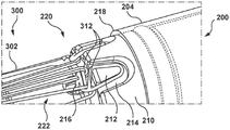
图20是在具有延伸的系绳的图6A所示的递送导管上的图15所示的装载工具的立体图。20 is a perspective view of the loading tool shown in FIG. 15 on the delivery catheter shown in FIG. 6A with an extended tether.
图21是在图6A所示的递送导管上的图15所示的装载工具的立体图,该附图示出了系绳的设置在装载工具的可枢转元件下的环。21 is a perspective view of the loading tool shown in FIG. 15 on the delivery catheter shown in FIG. 6A showing the loop of the tether disposed under the pivotable element of the loading tool.
图22A是图6A所示的递送导管的立体图,其中系绳中的一根穿过图7A所示的瓣膜假体的框架成环并由图15所示的装载工具捕获。22A is a perspective view of the delivery catheter shown in FIG. 6A with one of the tethers looped through the frame of the valve prosthesis shown in FIG. 7A and captured by the loading tool shown in FIG. 15 .
图22B是图6A所示的递送导管的近距离(closer)立体图,其中一根系绳穿过图7A所示的瓣膜假体的框架成环并由图15所示的装载工具捕获。22B is a closer perspective view of the delivery catheter shown in FIG. 6A with a tether looped through the frame of the valve prosthesis shown in FIG. 7A and captured by the loading tool shown in FIG. 15 .
图23是由图6A所示的递送导管的外套管捕获的多根系绳的立体图。Figure 23 is a perspective view of a plurality of tethers captured by the outer sheath of the delivery catheter shown in Figure 6A.
图24A是根据本发明一实施例的装载锥体的侧视图。24A is a side view of a loading cone according to an embodiment of the present invention.
图24B是图24A所示的装载锥体的一部分的侧视图。Figure 24B is a side view of a portion of the loading cone shown in Figure 24A.
图25A-25E是使用图24A所示的装载锥体将图7A所示的瓣膜假体装载到图6A所示的递送导管的囊状件中的立体图。Figures 25A-25E are perspective views of loading the valve prosthesis shown in Figure 7A into the balloon of the delivery catheter shown in Figure 6A using the loading cone shown in Figure 24A.
图26是图6A所示的递送导管的装载的囊状件的立体图。Figure 26 is a perspective view of the loaded balloon of the delivery catheter shown in Figure 6A.
发明详述Detailed description of the invention
现参照附图描述本发明的具体实施例,其中,相似的附图标记指示相同的或功能类似的元件。术语“远侧”和“近侧”在用于以下的描述中而涉及装载工具、导管或递送导管时是相对于有关治疗医师的位置或方向来使用。因此,“远侧”和“向远侧”是指远离治疗医师的位置或沿远离治疗医师的方向,并且“近侧”和“向近侧”是指靠近医师的位置或沿朝向医师的方向。当术语“远侧”和“近侧”在以下说明中涉及诸如假体心脏瓣膜之类的植入血管中的装置而使用时,它们是参考血流方向来使用的。因此,“远侧”或“向远侧”是指沿血流方向下游的位置,并且“近侧”和“向近侧”是沿血流方向上游的位置。Specific embodiments of the present invention are now described with reference to the drawings, wherein like reference numerals designate identical or functionally similar elements. The terms "distal" and "proximal" as used in the following description in reference to a loading tool, catheter or delivery catheter are used relative to the position or orientation of the treating physician. Thus, "distal" and "distal" refer to a location away from or in a direction away from the treating physician, and "proximal" and "proximal" refer to a location closer to or in a direction toward the physician . When the terms "distal" and "proximal" are used in the following description in reference to a device implanted in a blood vessel, such as a prosthetic heart valve, they are used with reference to the direction of blood flow. Thus, "distal" or "distal" refers to a position downstream in the direction of blood flow, and "proximal" and "proximal" refer to a position upstream in the direction of blood flow.
与本文所述的各种经导管系统、装置和方法一起使用和/或形成其一部分的心脏瓣膜假体(为简单起见,以下称为“瓣膜假体”)可呈现多种不同的构型,并且可以是专门构造成用于替换人类心脏的四个天然心脏瓣膜中的任意一个。因此,可用于本发明的系统、装置和方法的瓣膜假体通常可用于置换天然主动脉瓣、二尖瓣、肺动脉或三尖瓣,或者置换失效的瓣膜假体,比如可能先前植入在例如天然主动脉瓣或二尖瓣中的瓣膜假体。Heart valve prostheses for use with and/or forming part of the various transcatheter systems, devices, and methods described herein (for simplicity, hereafter referred to as "valve prostheses") can assume a number of different configurations, And can be any of the four native heart valves specially constructed to replace the human heart. Thus, valve prostheses useful in the systems, devices, and methods of the present invention may generally be used to replace native aortic, mitral, pulmonary, or tricuspid valves, or to replace failed valve prostheses, such as may have previously been implanted, for example, in Valve prostheses in native aortic or mitral valves.
通常而言,这种瓣膜假体包括限定内部区域的框架(支架),具有两个或更多个瓣膜瓣叶(组织或合成的)的瓣膜主体部分固定在该内部区域内。瓣膜假体的框架具有对应于在心脏内的具体目标部位处的植入的扩张或部署构型,以及当装载在也称为基于导管的递送装置的递送导管内或递送装置内以用于递送至心脏内的具体目标部位时的压缩或递送构型。通常,每个框架是支承结构,其包括相对于彼此布置的多个支杆或线材部段,以向瓣膜假体提供诸如可压缩性和强度之类的期望的特性。框架可构造成当从递送导管释放时从压缩构型自部署或自扩张至扩张构型。术语“自扩张”及该术语的其它形式在以下描述中使用,并旨在表达在本发明的实施例中使用的瓣膜假体的框架结构由可以提供机械记忆以将结构从压缩(递送)构型返回至扩张(部署)构型的材料成形或形成。非穷尽的示例性自扩张材料包括不锈钢、诸如镍钛合金或镍钛诺的伪弹性金属、各种聚合物或可具有镍、钴、铬、或其它金属的贱金属的所谓超合金。机械记忆可例如通过热处理以获得不锈钢中的弹簧回火、或者在诸如镍钛诺之类的敏感金属合金中设定形状记忆来施加至线材或支架框。可被制成为具有形状记忆特性的各种聚合物也可适用于本文的实施例中,包括诸如聚降冰片烯、反式聚异戊二烯、苯乙烯-丁二烯和聚氨酯之类的聚合物。并且,L-D乳酸共聚物、低聚辛酸内酯共聚物和聚环辛烯可以单独地或与其它形状记忆聚合物相结合地使用。作为示例,本公开的瓣膜假体可类似于美敦力(Medtronic)
图1-14示出了根据本发明一实施例的系统100和用于将经导管瓣膜假体(为简单起见,下文称为“瓣膜假体”)装载到递送导管中的方法。系统100包括装载工具102(为简单起见,下文称为“工具102”)和递送导管200。该系统100还包括装载构型和递送构型,在装载构型中,递送导管200被接纳在工具102的用于将瓣膜假体装载在其中的中心通道110内,在递送构型中,递送导管200未被接纳在工具102内。系统100构造成使得当系统100处于装载构型时,装载工具102协助将瓣膜假体装载到递送导管200中,如以下更详细描述的。1-14 illustrate a
在如图1-5所示的一实施例中,工具102包括主体部分104、多个可枢转元件136、及偏置元件162,如图1所示。工具102的主体部分104包括近端106、远端108和限定中心通道110的内表面,中心通道110从近端106向远侧延伸至远端108。中心通道110是沿着第一纵向轴线LA1延伸穿过主体部分104的整个纵向中心的开口(孔或内腔)。主体部分104的尺寸被设计并构造成可滑动地接纳从中通过的递送导管200的远侧部分。当工具102定位在递送导管200的远侧部分之上时,主体部分104进一步构造成协助将瓣膜假体300装载到递送导管200中。In one embodiment shown in FIGS. 1-5 , the
在图3A所示的一实施例中,主体部分104的中心通道110(如虚线所示)包括第一部分112和渐缩部分118。第一部分112从与主体部分104的近端106协同定位的近端114向远侧延伸至远端116,该远端116位于主体部分104的远端108近侧。第一部分112呈大致圆柱形并具有一致的第一直径D1。中心通道110的渐缩部分118从近端120延伸至远端122,近端120联接于第一部分112的远端116,并且远端122与主体部分104的远端108协同定位(co-located)。渐缩部分118从具有第一直径D1的近端120径向向外扩口至具有第二直径D2的远端122,其中,第二直径D2大于第一直径D1。因此,渐缩部分118具有大致圆锥形状,其中邻近主体部分104的远端108的较大的第二直径D2在第一部分112的协同定位的远端116处渐缩(减小直径)至近端120。渐缩部分118构造成在装载到递送导管200中的期间压缩瓣膜假体。中心通道110的渐缩部分118的锥形形状构造成在瓣膜假体装载到递送导管200中时容易(便于)瓣膜假体的径向压缩。在另一种实施例中,如图3B所示,主体部分104包括从近端106’延伸至远端108’的中心通道110’。中心通道110’是大致管状的形状,其具有一致的直径D3。主体部分104可由金属和/或聚合材料形成,比如但不限于聚乙烯、PEBA、聚酰胺和/或其组合。主体部分104可通过各种方法形成,这些方法的非限制性示例包括机械加工、挤出、模制或其它方法以及各方法的组合。In one embodiment shown in FIG. 3A , the central channel 110 (shown in phantom) of the
主体部分104还包括多个可枢转元件狭槽124(图4)。每个可枢转元件狭槽124是限定在主体部分104的外表面内的通道或凹部。在一实施例中,每个可枢转元件狭槽124由第一壁126、第二壁128和凹陷表面130限定,如图4所示。第一壁126和第二壁128大致垂直于第一纵向轴线LA1从主体部分104的外表面大致径向向外延伸。对应的第一壁126和第二壁128的面对的表面大致彼此平行并且沿着主体部分104从远端108(图1)纵向延伸,从而向近侧延伸至在近端106(图1)远侧的位置。每个可枢转元件狭槽124的宽度W的尺寸设计成将对应的可枢转元件136(图1)可枢转地接纳在其中。每个可枢转元件狭槽124包括枢转孔132。在一实施例中,如图4所示,枢转孔132横向于可枢转元件狭槽124延伸并穿过对应的第一壁126和第二壁128。每个枢转孔132构造成接纳从中通过的枢轴134,使得枢轴134延伸穿过第一壁126、对应的可枢转元件136(为清楚起见未在图4中示出)以及对应的第二壁128。枢轴134构造成使得对应的可枢转元件136(图1)可绕枢轴134枢转。因此,如图2A所示,枢轴134将对应的可枢转元件136联接在相应的可枢转元件狭槽124内,并且枢轴134是枢转点,对应的可枢转元件136可绕该枢转点枢转。在一实施例中,枢轴134是销或轴。虽然图1-4的实施例示出了具有六(6)个可枢转元件狭槽124的主体部分104,但是应当理解的是,根据应用场合,可提供更多或更少的可枢转元件狭槽124和对应的可枢转元件136。此外,虽然可枢转元件狭槽124和对应的可枢转元件136被示出为绕工具102的周界等距地间隔开,但这并不意味着限制设计,并且可枢转元件狭槽124和对应的可枢转元件136可不绕工具102的周界等距地间隔开。The
如图1所示,工具102包括多个可枢转元件136。图5更详细地示出了可枢转元件136中的一个。每个可枢转元件136构造成在将瓣膜假体装载到递送导管中的期间固定递送导管的对应系绳,如以下更详细地描述的。每个可枢转元件136包括第一端142和第二端144。第一端142朝向主体部分104的近端106,第二端144邻近主体部分104的远端108。在一实施例中,每个可枢转元件136的第二端144向远侧延伸超出主体部分104的远端108。每个可枢转元件136至少部分地在对应的可枢转元件狭槽124内沿着主体部分104的外表面纵向延伸。如前所述,每个可枢转元件136通过相应的枢轴134可枢转地联接于主体部分104。在一实施例中,每个可枢转元件136还包括弯曲部148和位于第二端144处的接触表面150。如图1所示,弯曲部148构造成使得可枢转元件136的第二端144朝向主体部分104的位于主体部分104的远端108的远侧的第一纵向轴线LA1径向向内弯曲。更具体地,如图1所示,弯曲部148构造成使得当每个可枢转元件136处于第一(闭合)构型时,每个可枢转元件136的位于第二端144处的接触表面150大致平行于第一纵向轴线LA1对准。在一实施例中,每个可枢转元件136的第二端144通过以下描述的偏置元件162(图1)朝向第一纵向轴线LA1偏置。因此,当每个可枢转元件136处于第一(闭合)构型时,每个可枢转元件136的相应接触表面150朝向工具102的第一纵向轴线LA1偏置。此外,如图2A所示,当每个可枢转元件136处于以下更详细描述的第二(打开)构型时,相应的可枢转元件136的第二端144从工具102的主体部分104的远端108径向向外设置。As shown in FIG. 1 , the
在一实施例中,如图2A所示并且在图5中更详细地示出的,每个可枢转元件136还包括枢转狭槽152。在一实施例中,每个枢转狭槽152是横向穿过可枢转元件136的主体部分延伸的椭圆形孔。当可枢转元件136联接于主体部分104时,枢转狭槽152与对应的枢转孔132对准。枢转狭槽152与枢转孔132对准,使得对应的枢轴134可以从中通过其设置。枢转狭槽152构造成使得可枢转元件136可绕对应的枢轴134枢转。枢转狭槽152包括第一(近侧)端154和第二(远侧)端156。当可枢转元件136处于第二构型(图2A)或第三(锁定打开(lockedopen))构型(图2B)时,枢转狭槽152包括大致平行于主体部分104的第一纵向轴线LA1对准的第二纵向轴线LA2。当处于第二构型或第三构型时,枢转狭槽152可相对于枢轴134滑动或平移,因此对应的可枢转元件136可相对于主体部分104滑动或平移,如下所述。In one embodiment, as shown in FIG. 2A and shown in greater detail in FIG. 5 , each
在一实施例中,如图1所示并且在图5中更详细地示出的,每个可枢转元件136还包括致动器表面146。每个致动器表面146构造成用于使用者操纵以使对应的可枢转元件136绕对应的枢轴134枢转。在一实施例中,每个致动器表面146设置成与可枢转元件136的对应第一端142相邻。每个致动器表面146是背离主体部分104的第一纵向轴线LA1径向向外的表面。每个致动器表面146可在其上包括纹理以有助于可枢转元件136的操纵。虽然致动器表面146在本文中描述为与可枢转元件136的第一端142相邻地设置,但这并不意味着限制设计,并且致动器表面146可设置在适合于本文所述目的的其它位置。In one embodiment, as shown in FIG. 1 and shown in greater detail in FIG. 5 , each
在一实施例中,如图1所示并且在图5中更详细地示出的,每个可枢转元件136还包括在每个可枢转元件136的外表面160上的偏置狭槽158。偏置狭槽158设置在每个可枢转元件136的第一端142与第二端144之间。本文描述的外表面160是可枢转元件136的背离主体部分104的第一纵向轴线LA1径向向外的表面。每个偏置狭槽158的尺寸设计成和构造成将偏置元件162接纳在其中,使得偏置元件162朝向第一纵向轴线LA1偏置第二端144。每个偏置狭槽158可通过包括但不限于铸造、机械加工或适合于本文所述目的的其它方法的方法形成为可枢转元件136的成一体的部件。In one embodiment, as shown in FIG. 1 and shown in greater detail in FIG. 5 , each
在一实施例中,每个可枢转元件136可相对于主体部分104以第一或闭合构型(图1)、第二或打开构型(图2A)以及第三或锁定打开构型(图2B)定位。或者,在其它实施例中,每个可枢转元件136可仅包括第一构型和第二构型。在第一构型中,如图1所示,相应的可枢转元件136的接触表面150基本平行于装载工具102的第一纵向轴线LA1并偏置到第一纵向轴线LA1。此外,当处于第一构型时,枢轴134设置在枢转狭槽152的第二(远侧)端156处。此外,当可枢转元件136处于第一构型并且系统100处于装载构型时,可枢转元件136的接触表面150构造成接触递送导管200的外表面并且在将瓣膜假体300装载在递送导管200中的期间固定递送导管的系绳,如以下更详细地描述的。在第二构型中,相应的可枢转元件136的接触表面150从主体部分104(图2A)径向向外设置,并且当系统100处于装载构型时不接触递送导管200的外表面。进一步地,当可枢转元件136处于第二构型时,枢轴134设置在枢转狭槽152的第二(远侧)端156处,使得可枢转元件由偏置元件162偏置以返回至第一构型。在第三构型中,可枢转元件136在对应的可枢转元件狭槽124内并且相对于主体部分104向远侧滑动或平移,并且锁定到第三构型中。在第三构型中,相应的可枢转元件136的接触表面150从主体部分104(图2B)径向向外设置,并且当系统100处于装载构型时不接触递送导管200的外表面。此外,当可枢转元件136处于第三构型时,枢轴134设置在枢转狭槽152的第一(近侧)端154处。在枢轴134设置在枢转狭槽152的第一(近侧)端154处,并且可枢转元件136的第一端142朝向纵向轴线LA1推动的情况下,可枢转元件的旋转中心已经移位,使得偏置元件162将可枢转元件126朝向第三构型偏置。这允许可枢转元件136保持打开而没有压力施加至表面146。通过使用者将向内径向力施加至可枢转元件的近侧部分,每个可枢转元件136可从第一构型转换到第二构型。通过使用者将远侧纵向力施加至可枢转元件136,每个可枢转元件136可从第二构型转换到第三构型。In one embodiment, each
如图1中所示,工具102还包括偏置元件162。通常,偏置元件162在每个可枢转元件136上施加向内的径向力。在一实施例中,偏置元件162是弹性带,其环绕(周向地围绕)多个可枢转元件136并且被接纳在每个可枢转元件136的对应偏置狭槽158内。偏置元件162是具有预设塌缩状态的弹性或形状记忆材料。弹性结构允许偏置元件162在被操纵时伸展或扩张至扩张状态,并且在未操纵时返回至塌缩状态。当绕可枢转元件136设置时,偏置元件162处于扩张状态。因为偏置元件162预设为塌缩状态,所以偏置元件162向可枢转元件136施加向内径向力(压缩)。更具体地,当系统100处于装载构型并且多个可枢转元件136处于第一构型时,偏置元件162构造成施加向内径向力,使得对应的可枢转元件136的每个第二端144处的接触表面150保持抵靠递送导管并且将对应的系绳捕获在其中。进一步地,当任一可枢转元件136处于第二构型时,偏置元件162在可枢转元件136的远侧部分上施加向内径向力,使得当可枢转元件136不再被使用者操纵至第二构型时,可枢转元件136将返回至第一构型。此外,当任一可枢转元件136处于第三构型时,偏置元件162施加向内径向力以将可枢转元件136朝向第三构型偏置。在所示的实施例中,偏置元件是由诸如但不限于天然橡胶或合成橡胶、聚酯、弹性纤维之类的材料或适于本文所述目的的任何其它材料制成的弹性带。然而,偏置元件162还可以是其它类型的可以如述的那样偏置可枢转元件136的装置。例如而非限制地,偏置元件可包括盘绕件、弹簧、可动配重或其它类似的偏置装置。As shown in FIG. 1 , the
现在可更详细地描述可枢转元件136的操作和转换。在先前参照图1-2B描述的实施例中,工具102的每个可枢转元件136可设置在第一构型、第二构型和第三构型中。为了将每个可枢转元件136从第一构型(图1)转换到第二构型(图2A),相应可枢转元件136的致动器表面146由使用者利用沿箭头137(图2A)的方向向其施加的向内径向力来操纵。向内径向力的施加使可枢转元件136绕枢轴134枢转,从而使可枢转元件136从第一构型转换到第二构型。如果使用者对致动表面146移除了所施加的力,则由偏置元件162施加至可枢转元件136的远侧部分的向内径向力(偏置)将使可枢转元件136从第二构型转换回第一构型。为了将每个可枢转元件136从第二构型(图2A)转换到第三构型(图2B),可枢转元件136的致动器表面146可利用沿箭头138(图2A)的方向向其施加的向内径向力来操纵。向远侧施加至可枢转元件136的纵向力的施加使可枢转元件136在对应的可枢转元件狭槽124内向远侧滑动/平移。进一步地,随着可枢转元件136向远侧滑动,可枢转元件136的枢转狭槽152在枢轴134上向远侧滑动,使得枢轴134有效地从枢轴槽152的第二端156滑动/平移至第一端154(图2B)。由于枢轴134的位置的移位,由偏置元件162施加至可枢转元件136的向内径向力将可枢转元件136保持或锁定在第三构型中,而无需持续的使用者操纵。在施加沿箭头140(图2B)的方向向近侧施加至致动器表面146的纵向力的情况下,可枢转元件136可从第三构型转换到第二构型。在沿近侧方向施加纵向力的情况下,可枢转元件136在对应的可枢转元件狭槽124内向近侧滑动/平移,从而将可枢转元件136从第三构型转换到第二构型,并且可枢转元件136的释放将其转换到第一构型。The operation and switching of the
图6A-6B示出了系统100的递送导管200的一示例性实施例,本文所述的工具102的各实施例可与该递送导管200一起使用。递送导管200构造成将瓣膜假体递送至有缺陷的心脏瓣膜或有缺陷的瓣膜假体的部位。递送导管200可类似于Creaven等人的美国专利申请公开第2015/0112430中描述的递送导管,其全文以参见的方式纳入本文。通常而言,也称为递送装置的递送导管200包括手柄组件201、内轴组件202、外套管204和远侧(扩张器)末端206。外套管204和远侧末端206组合以形成囊状件208。囊状件208构造成将瓣膜假体以压缩构型保持在其中,以用于递送至期望的治疗位置。如图6B所示,递送导管200还包括瓣膜保持件210。瓣膜保持件210构造成保持瓣膜假体的一部分,以用于将瓣膜假体装载到递送导管200的囊状件208中。更具体地,瓣膜保持件210包括至少一个系绳柱212、围绕每个系绳柱212的近侧部分的对应凹槽214、以及对应的系绳216。每根系绳216是细长构件,其具有联接于递送导管200的第一端和第二端。每根系绳构造成将瓣膜假体可释放地联接至递送导管200,以将瓣膜假体装载在递送导管200中,如以下更详细地描述的。更具体地,每根系绳216穿过瓣膜假体的一部分并(在对应的凹槽214内)绕对应系绳柱212的近侧部分成环,使得瓣膜假体可释放地联接于递送导管。6A-6B illustrate an exemplary embodiment of a
图7A-7B示出了与本文所述的系统、装置和方法一起使用的瓣膜假体300的一实施例。例如而非限制地,瓣膜假体300可包括美敦力血管公司(Medtronic Vascular,Inc.)的W.I.P.O.公开号WO 2016/133950中描述的特征,其全部内容以参见的方式纳入本文。更具体地,图7A和7B示出了从瓣膜假体300的剩余部分移除的处于扩张(部署)构型的框架302。图7A是框架302的侧视图,并且图7B是沿图7A中的线7B-7B的方向截取的框架302的顶视图或流入视图(inflow view)。框架302可以是限定流入部分304和瓣膜保持管状部分306的整体结构。框架302的第一或流入端308以及第二或流出端310大致由框架302的支杆314形成的多个相应的冠部312限定。在根据本文的各实施例中,框架302可形成为自扩张的,因此当被装载在递送导管内时可以受迫和约束成压缩构型。如图7A所示框架302包括形状记忆,以在移除递送导管的(一个或多个)约束力时自扩张并返回至其自然的扩张构型。7A-7B illustrate one embodiment of a
尽管图7A-7B示出了示例性瓣膜假体300的具体实施例,但应当理解的是,本申请的装置和方法可与其它心脏瓣膜假体或其它假体一起使用。进一步地,如上所述,图7A-7B未示出附连于框架302的假体瓣膜,或诸如裙部等之类的其它特征。7A-7B illustrate a specific embodiment of an
考虑到上述结构和部件,并转向图8A,递送装置200的外套管204用于相对于对应的系绳柱212保持系绳216。作为参照,图8A而示出了外套管204的远端218,为了便于说明,该远端218位于系绳柱212的近侧。然而,在递送导管200的递送状态下,远端218位于系绳柱212的远侧,以便维持系绳216与系绳柱212的配合。进一步地,在递送状态下,远端218位于瓣膜假体300的远侧,以将瓣膜假体300约束成压缩构型。With the above structures and components in mind, and turning to FIG. 8A , the
根据本公开,(一根或多根)系绳、瓣膜假体与递送导管的其它部件之间的连接可以呈现多种形式。例如,图8A示出了递送导管200的一部分,该部分联接于瓣膜假体300的框架302的一部分,如前所述。递送导管200包括外套管204、内轴组件202(在图8A中主要隐藏但在图8B中示出)、以及接口组件220。接口组件220包括瓣膜支承件222、瓣膜保持件210和多根系绳216。瓣膜保持件210附连于内轴组件202或由内轴组件202形成,并形成多个系绳柱212(其中一个在图8A中可见)。凹槽214绕每个系绳柱212限定,并且尺寸设计成将对应的系绳216接纳在其中并围绕系绳柱212。在由图8A大致反映的递送状态中,系绳216中的每一根从瓣膜保持件210延伸并且穿过瓣膜假体300的框架302成环。例如,如图8A所示,系绳216穿过或绕形成在框架302的第一端304处的两个冠部312成环。图8B是递送导管200的一部分的简化剖视图,并且反映了系绳216绕对应凹槽214内的对应系绳柱212成环,从而有效地限定从系绳柱212延伸的第一系绳部段216a和第二系绳部段216b。系绳部段216a、216b穿过框架302(图8A)成环,然后向近侧引导穿过瓣膜保持件210。系绳部段216a、216b可以延伸至递送导管200的手柄组件201(未示出),或者可以连接于递送导管200的适于方便使用者控制系绳216中的张力的另一个部件。In accordance with the present disclosure, the connection between the tether(s), the valve prosthesis, and other components of the delivery catheter may take a variety of forms. For example, FIG. 8A shows a portion of
在理解系统100的部件的情况下,并参照图9-14,现在可以描述这些部件的相互作用以及利用图3A所示的工具102的实施例将瓣膜假体300装载到递送导管200中的方法。With an understanding of the components of the
参照图9,工具102装配在递送导管200的远侧部分之上。更具体地,递送导管200的远侧末端206放置到工具102的主体部分104的中心通道110的近端106中,并且工具102在递送导管200的远侧部分上向近侧运动。或者,递送导管200可通过工具102的中心通道410向远侧前进。工具102定位在递送导管200的外套管204的远侧部分之上。如图9所示,工具102位于外套管204的远端218的近侧。然而,工具102向远侧前进,直到每个可枢转元件136的接触表面150定位成使接触表面150的远端与对应的系绳柱212的远端对准为止。工具102周向对准,使得每个可枢转元件136的接触表面150沿着相应的系绳柱212的纵向中心线定位。外套管204的远端218位于瓣膜保持件210的近侧,使得每个可枢转元件136搁置在对应的系绳柱212上。在图9中,系绳216显示为处于缩回位置。偏置元件在每个可枢转元件136上朝向第一纵向轴线LA1施加向内径向压力(压缩),使得每个可枢转元件136的接触表面与相应的系绳柱212保持物理接触。Referring to FIG. 9 , the
如图10所示,在多个可枢转元件136的每个接触表面150与相应的系绳柱212接触的情况下,通过操纵手柄组件201(未示出)来使多根系绳216延伸以形成大的环。As shown in FIG. 10, with each
一旦多根系绳216成为大环,瓣膜假体300就连接于递送导管200的瓣膜保持件210。在一实施例中,如图11所示,每根系绳216绕或穿过瓣膜假体300的两个冠部312成环。或者,系绳216可绕更多或更少的冠部312或绕支杆314成环,或绕任何其它结构或适合于本文所述目的的任何组合成环。接着,使用者致动对应的可枢转元件136,以将可枢转元件136从第一构型转换到第二构型。更具体地,向内的径向力被施加至相应的可枢转元件136的致动器表面146,以将可枢转元件136从第一构型转换到第二构型。如图11中大致所示,一旦可枢转元件136处于第二构型,系绳216就绕递送导管200的相邻凹槽214内的对应系绳柱212成环。在系绳216绕系绳柱212并且在相邻凹槽214内成环之后,使用者释放可枢转元件136。更具体地,使用者施加在可枢转元件136的致动表面146上的向内径向力被释放。在释放可枢转元件136时,偏置元件162在可枢转元件136的远侧部分上施加向内径向力,并且可枢转元件136从第二构型枢转至第一构型。如图11所示,在转换到第一构型时,可枢转元件136的接触表面150接触系绳柱212并覆盖相邻的凹槽214。偏置元件162在每个可枢转元件136上施加向内径向力,使得每个可枢转元件136的接触表面150压缩地压靠相应的系绳柱212,从而保持对应的系绳216。对于每根系绳216以及递送导管200的对应系绳柱212完成该动作。或者,在将每根系绳216绕对应的系绳柱212并且在相邻的凹槽214内成环之前,可枢转元件136可从第二构型转换到第三构型,然后在每根系绳216设置在相应的凹槽214中之后返回至第一构型。Once the plurality of
当多根系绳216由瓣膜保持件210和设置在其上的多个可枢转元件136保持时,手柄组件201(未示出)由使用者操纵,并且多根系绳216缩回以消除松弛。一旦消除松弛,就通过操纵手柄组件201(未示出)使递送导管200的外套管204向远侧运动。随着外套管204向远侧前进,它将在每个可枢转元件136的每个接触表面150上提升(在每个可枢转元件136的每个接触表面150下滑动),从而覆盖相应的凹槽214和系绳柱212并将(一根或多根)系绳216保持在其中。因此,如图12所示,每根系绳216通过外套管204的内表面保持在相应的凹槽214中并绕对应的系绳柱212保持,为了清楚起见,多个可枢转元件136处于第三构型中(即,可枢转元件136将处于第一构型)。因此,瓣膜假体300可释放地联接于递送导管200。When the plurality of
一旦瓣膜假体300可释放地联接于递送导管200,每个可枢转元件136就被致动,使得每个可枢转元件136如前所述地从第一构型转换到第二构型,然后到第三构型,如图13A中大致反映的那样。更具体地,致动器表面146通过施加向远侧施加至其的纵向力来操纵。向远侧施加至可枢转元件136的致动器表面146的纵向力在对应的可枢转元件狭槽124内向远侧滑动/平移可枢转元件136,从而使可枢转元件136从第二构型转换到第三构型。如前所述,可枢转元件136将保持在第三构型中,直到由使用者转换到第二构型为止。对于工具102的每个可枢转元件136完成该动作。Once
在瓣膜假体300可释放地联接于递送导管200和处于第三构型的每个可枢转元件136的情况下,该工具相对于外套管204向远侧前进,使得工具102的远端118位于外套管204的远端218的远侧。接着,通过操纵手柄组件201(未示出)使外套管204向远侧前进,并且工具102与外套管204一起向远侧前进,使得瓣膜假体300在前进的外套管204(图13A)和工具102内径向塌缩。工具102的渐缩部分118(图13B)协助使瓣膜假体300径向塌缩。如图所示,如果瓣膜假体包括臂320,这些臂320可放置在工具之上(图13B),使得当外套管204和工具102前进时臂320外翻,如图13B-13D所示。图13A-13D示出了瓣膜假体300缓慢径向塌缩和装载到递送导管200的外套管204中。如图14所示,外套管204前进直到远端218接触远侧末端206的近端为止。压缩的瓣膜假体300现在保持在递送导管200的囊状件208内。现在可通过使装载工具102从递送导管200的远端向远侧滑动来将装载工具102从递送导管200移除。With
虽然在具体步骤中通过多个可枢转元件136的特定构型描述了前述方法,但是这并不意味着限制该方法,并且每个步骤中的每个可枢转元件136的具体步骤和构造的顺序可由使用者根据期望或针对特定应用场合或基于使用者偏好而改变。例如,在可枢转元件转换到第二构型的任何时候,使用者可选地可将可枢转元件136转换到第三构型。类似地,在可枢转元件转换到第三构型的任何时候,使用者可选择将可枢转元件保留在第二构型中。Although the foregoing method is described with specific configurations of the plurality of
虽然参照图3A所示的实施例描述了先前的程序,但是工具102的其它实施例、比如但不限于图3B的实施例可采用类似的程序并进行微小的修改。例如,在图3B所示的工具102’的实施例中,在瓣膜假体300可释放地联接于递送导管200之后并且在使瓣膜假体300塌缩到囊状件208中之前,利用在工具102’的远端处定位塌缩锥体的附加步骤来修改该程序。如本领域技术人员所理解的,塌缩锥体定位成协助使瓣膜假体300塌缩成径向压缩构型,以便装载到递送导管200的囊状件208中。Although the previous procedure was described with reference to the embodiment shown in Figure 3A, other embodiments of the
图15-25示出了根据本发明另一种实施例的系统400和用于将瓣膜假体装载到递送导管中的方法。系统400包括装载工具402(为简单起见,下文称为“工具402”)和递送导管、比如前述的递送导管200。该系统400还包括装载构型和递送构型,在装载构型中,递送导管200被接纳在工具402的用于将瓣膜假体(未示出)装载在其中的中心通道410内,在递送构型中,递送导管200未被接纳在工具402内。系统400构造成使得当系统400处于装载构型时,装载工具402协助将瓣膜假体装载到递送导管200中,如以下更详细描述的。15-25 illustrate a
在一实施例中,如图15-19所示,工具402类似于先前描述的工具102。通常,工具402包括主体部分404、中心通道410、多个可枢转臂436、以及偏置元件462。装载工具402构造成协助将瓣膜假体、比如前述的瓣膜假体300装载到递送导管的囊状件、比如先前描述的递送导管200的囊状件208中。因此,此处将不描述工具402的类似结构和替代方案。然而,与工具102不同,工具402包括固定装置470。进一步地,在一实施例中,工具402包括枢转孔432而不是枢转狭槽。In one embodiment, as shown in Figures 15-19,
如图15中所示并且在图17中更详细地示出的,工具402的主体部分404包括近端406、远端408和中心通道410。中心通道410从近端406向远侧延伸至远端408。中心通道410是沿着第一纵向轴线LA1延伸穿过主体部分404的整个纵向中心的开口(孔或内腔)。主体部分404构造成滑动到(滑过)递送导管的远侧部分或替代地在中心通道410内接纳递送导管的远侧部分。当定位在递送导管的远侧部分之上时,主体部分404进一步构造成协助将瓣膜假体装载到递送导管中。在一实施例中,中心通道410还构造成在其近侧部分中接纳固定装置470的一部分。As shown in FIG. 15 and in greater detail in FIG. 17 , the
在图17所示的实施例中,主体部分404的中心通道410(如虚线所示)包括可攻丝(threadable)部分412、渐缩部分418和远侧部分419。可攻丝部分412从与主体部分404的近端406协同定位的近端414向远侧延伸至远端416,该远端416位于主体部分404的远端408近侧。近侧部分412呈大致圆柱形并具有一致的第一直径D1。在一实施例中,近侧部分412的内表面包括多个螺旋形螺纹413(为简单起见,下文中称为“螺纹413”)。螺纹413构造成当设置在固定装置470中时接纳并配合固定装置470的对应的多个螺旋形螺纹498(为简单起见,下文中称为“螺纹498”),如以下更详细地描述的。中心通道410的渐缩部分418从近端420延伸至远端422,近端420联接于近侧部分412的远端416,并且远端422位于远端414的近侧。渐缩部分418从具有第一直径D1的近端420径向向内渐缩至具有第二直径D2的远端422,其中,第二直径D2小于第一直径D1。因此,渐缩部分418具有大致截锥形状,其中近端420处的较大的第一直径D1向远侧向下渐缩(直径减小)至远端422。渐缩部分418构造成当固定装置470设置在渐缩部分418中时在固定装置470的远侧部分上提供增大的向内径向力,如以下更详细地描述的。远侧部分419从与渐缩部分418的远端422协同定位的近端421向远侧延伸至远端423,远端423协同定位于主体部分404的远端408处。近侧部分412呈大致圆柱形并具有一致的第二直径D2。虽然近侧部分412示出了螺纹413的特定数量、螺距和旋向性,但是这并不意味着限制本发明,并且螺纹413可具有更多或更少的数量、具有更大或更小的螺距和不同的旋向性。此外,螺纹413可以是中心通道410的近侧部分412的成一体的部件,或者可以是通过诸如但不限于粘合剂、结合之类的方法或适合于本文所述目的的其它方法联接于中心通道410的近侧部分412的单独部件。主体部分404可由金属和/或聚合材料形成,比如但不限于聚乙烯、PEBA、聚酰胺和/或其组合。主体部分404可通过各种方法形成,这些方法的非限制性示例包括机械加工、挤出、模制或其它方法以及各方法的组合。In the embodiment shown in FIG. 17 , the central channel 410 (shown in phantom) of the
工具402包括多个可枢转元件436。在图15中所示并且在图18中更详细地示出的一实施例中,每个可枢转元件436在结构上类似于图1的多个可枢转元件136,并且是可枢转元件136的替代物,除了每个可枢转元件436包括枢转孔452而不是枢转狭槽452。如图16所示,每个枢转孔452是圆形孔,其横向延伸穿过可枢转元件436并与对应的枢转孔432对准,使得对应的枢轴434可以从中通过枢转孔设置。因此,可枢转元件436可绕相应的枢轴434枢转。每个可枢转元件436可在第一(闭合)构型和第二(打开)构型之间枢转。如图15所示,在第一构型中,当系统400处于装载构型时,可枢转元件436的接触表面450接触递送导管200的外表面。如图16所示,在第二构型中,相应的可枢转元件436的接触表面450设置在第一纵向轴线LA1的径向外侧,并且当系统400处于装载构型时不接触递送导管200的外表面。
偏置元件462类似于先前描述的偏置元件162。因此,此处将不包括偏置元件462的细节。在一实施例中,偏置元件462是绕可枢转元件436周向设置的弹性带。偏置元件462设置在每个可枢转元件436(图18)中的狭槽458中。
工具402还包括固定装置470。该固定装置470构造成在将瓣膜假体装载到递送导管中的期间将工具402固定或可释放地联接至递送导管。在一实施例中,如图19所示,固定装置470构造成与中心通道410(图15)螺纹陪配并可拧紧到递送导管上。更具体地,固定装置470的远侧部分构造成被接纳在中心通道410(图15)的对应部分内。在一实施例中,固定装置470包括主体472和内腔474。固定装置470的主体472包括近端476、远端478和内腔474。内腔474从近端476延伸至远端478。内腔474是沿着纵向轴线LA2延伸穿过固定装置470的主体472的整个纵向中心的开口(孔)。内腔474包括直径D3并且构造成接纳从中通过的递送导管的远侧部分。在图19所示的实施例中,主体472包括可抓持部分480、螺纹部分486、以及夹头部分或多个指状部492。固定装置470的包括可抓持部分480、螺纹部分486和多个指状部492的主体472可由金属和/或聚合物材料形成,比如但不限于聚乙烯、PEBA、聚酰胺和/或其组合。主体2及其部件可通过各种方法形成,这些方法的非限制性示例包括机械加工、挤出、模制或其它方法以及各方法的组合。
可抓持部分480从与主体472的近端476协同定位的近端482向远侧延伸至远端484,该远端484位于主体472的远端478的近侧。可抓持部分480呈大致圆柱形并且构造成设置在工具402的主体部分404的近侧。可抓持部分480还构造成使得可抓持部分480的操纵使固定装置470与主体部分404可释放地联接或分离,并因此使工具402与从中通过其设置的递送装置200可释放地联接或分离。可抓持部分480的外径向表面可在其上包括形状或纹理以有助于可抓持部分480的操作。The
固定装置470的螺纹部分486从近端488延伸至远端490,近端488联接于可抓持部分480的远端484,并且远端490位于固定装置470的远端478的近侧。螺纹部分486呈大致圆柱形并且构造成设置在工具402的主体部分404的近侧部分412内。在一实施例中,螺纹部分486的外表面包括螺纹498。螺纹498构造成配合工具402的主体部分404的对应螺纹413,使得固定装置470以及与其联接的螺纹498的旋转使固定装置470在主体部分404的中心通道410内向远侧或向近侧平移(轴向运动)。螺纹部分486在图19中示出为具有特定的数量、螺距和旋向性,然而,这并不意味着限制本发明,并且螺纹498对应于中心通道410的螺纹413可具有的更多或更少的数量、具有更大或更小的螺距以及不同的旋向性。螺纹498可以是固定装置470的成一体的部件,或者可以是通过诸如但不限于粘合剂、结合之类的方法或适合于本文所述目的的其它方法联接于固定装置的单独部件。The threaded
多个指状部492从与螺纹部分486的远端490协同定位的近端494向远侧延伸至远端496。多个指状部492构造成设置在工具402的中心通道410主体部分404的渐缩部分418(图17)内。多个指状部492还构造成在施加向其施加的径向力时径向变形。虽然固定装置470示出为具有四(4)个指状部492,但这并不意味着限制本发明,并且可采用更多或更少的指状部492。A plurality of
通过理解系统400的组件,并参照图20-26,现在可以描述使用先前关于图7A-7B描述的示例性瓣膜假体300将瓣膜假体装载到先前关于图6A-6B和图8A-8B描述的递送导管200的方法,该递送导管200采用图15所示的工具402的实施例。With an understanding of the components of the
参照图20,工具402装配在递送导管200的远侧部分之上。更具体地,递送导管200的远侧末端206放置到装载工具402的中心通道410的近端406中,并且工具102在递送导管200的远侧部分上向近侧运动。装载工具402定位在递送导管200的远侧部分上(并且更具体地,外套管204),其中装载工具402的每个可枢转元件436的每个接触表面450定位成使接触表面450的远端与对应的系绳柱212的远端对准。每个可枢转元件436的接触表面450纵向对准,使得接触表面450覆盖对应的系绳柱212和对应的凹槽214。装载工具402周向对准,使得每个可枢转元件436的接触表面450沿着对应的系绳柱212的纵向中心线定位。如图20所示,外套管204的远端位于系绳柱212的近侧。装载工具402的偏置元件462在每个可枢转元件436上向内朝向工具主体部分404的第一纵向轴线LA1向内径向地施加,使得每个可枢转元件436的接触表面450将保持与相应系绳柱212物理接触。Referring to FIG. 20 ,
一旦装载工具402适当地正确定位在递送导管200的远侧部分之上,其中多个可枢转臂436的接触表面450设置在对应的系绳柱212上并与对应的系绳柱212接触,固定装置470的可抓持部分480就沿第一方向旋转,使得固定装置470的螺纹498(图19)与中心通道410(图17)的对应螺纹413(图17)接合,以使固定装置470在中心通道410内并且相对于主体部分404向远侧(沿箭头497的方向,如图20所示)运动(平移)。固定装置470相对于主体部分404的远侧运动使固定装置470的多个指状部492进一步向远侧运动到渐缩部分418中。随着多个指状部492进一步向远侧前进到中心通道410的渐缩部分418中,渐缩部分418的减小直径在设置于其中的多个指状部492上施加增大的向内径向力(压力)。由中心通道410的壁施加的向内径向力(压力)使指状部492径向向内变形。随着指状部492在中心通道410的渐缩部分418内持续向远侧运动,指状部492的变形增加,直到多个指状部492的内表面接触设置在其中的外套管204的外表面,以将工具402可释放地联接(抓握或固定)至递送导管200的外轴204为止。将工具402固定至递送导管200确保了工具402在固定系绳期间不会运动,如下所述,从而使用户能够使用双手来固定系绳。接着,在工具402可释放地联接于递送导管200的外套管204并且每个可枢转元件436的接触表面450与相应的系绳柱212接触的情况下,多根系绳216通过操纵手柄组件201(未示出)而延伸,以形成如图20所示的大环。Once the
一旦系绳216成为大环,瓣膜假体300就连接于递送导管200的瓣膜保持件210。图21示出了当使用者按压可枢转元件436的致动表面446时,每根系绳216如何在其自身上对折并且可以插入到系绳柱212的凹槽214中。为清楚起见,图21中未示出瓣膜假体300。在实践中,在一实施例中,每根系绳216绕或穿过瓣膜假体300的两个冠部312成环。然后,使用者致动对应的可枢转元件436,以将可枢转元件436从第一构型转换到第二构型。如图22A-22B中大致所示,一旦可枢转元件436处于第二构型,系绳216就绕对应的系绳柱212在其对应的凹槽214内成环。当相应的系绳216绕系绳柱212并在相邻的凹槽214中成环时,使用者使可枢转元件436退动(deactuate)。更具体地,移除使用者施加在可枢转元件436上的向内径向压力(力)。当移除使用者致动的向内径向压力(力)时,偏置元件462在可枢转元件436的远侧部分上施加向内径向力。来自偏置元件462的向内径向力使可枢转元件436枢转至第一(闭合)构型,并且接触表面450接触系绳柱212,从而覆盖系绳柱212和相邻凹槽214。当与系绳柱212接触并覆盖凹槽214时,接触表面450将对应的系绳216保持在其中。对于每根系绳216以及递送导管200的对应系绳柱212完成该动作。Once the
一旦多根系绳216绕相应的系绳柱212成环并通过相应的可枢转元件436保持在对应的凹槽214内,固定装置470的可抓持部分480就沿与第一方向相反的第二方向旋转。可抓持部分480沿第二方向的旋转使固定装置470相对于工具402的主体部分404向近侧运动。更具体地,固定装置470的多个指状部492在中心通道410的渐缩部分418内向近侧运动,并且渐缩部分418的增大直径释放多个指状部492上的向内径向力(压力)。减小的向内径向力(压力)允许多个指状部492(图19)返回至其原始(未变形)形状,并且多个指状部492的内表面从外套管204的外表面脱离,以使工具402与递送导管200分离。然而,工具402的主体部分404保持就位,使得可枢转元件436将系绳216保持在围绕系绳柱212的凹槽214内。上述固定装置470的松动允许外轴404与工具402之间的相对运动,但是工具402由使用者保持就位。Once the plurality of
一旦系绳216绕系绳柱212固定并且工具402已松驰,就通过操纵手柄组件201(未示出)使递送导管200的外套管204向远侧运动。随着外套管204向远侧前进,它将在每个可枢转元件436的每个接触表面450(图22B)上提升(在每个可枢转元件436的每个接触表面450下滑动),从而覆盖相应的凹槽214和系绳柱212并将系绳216保持在其中。因此,如图23所示,每根系绳216通过外套管204的内表面保持在相应的凹槽214中并绕对应的系绳柱212保持,并且瓣膜假体300可释放地联接于递送导管200。Once the
如图23所示,在瓣膜假体300可释放地联接于递送导管200的情况下,工具402可远离外套管204的远端218向近侧缩回。此外,如图23所示,手柄组件201由使用者操纵,并且多根系绳216缩回以消除松弛。As shown in FIG. 23 , with
接着,装载锥体500可定位在远端218附近的外套管204之上。图24A和24B中示出了装载锥体500。在一实施例中,装载锥体500包括构造成彼此相联接的第一主体部分5023a和第二主体部分502b。如图24A所示,第一主体部分502a和第二主体部分502b沿着纵向分型线(parting line)502分开。第一主体部分502a和第二主体部分502b可通过将每个主体部分的周向边缘520、522进行匹配而联接在一起(参见图24B)。边缘520、522可包括将第一主体部分502a和第二主体部分502b联接在一起的特征,比如但不限于主体部分之一的一个边缘中的突起与另一个主体部分的对应边缘中的对应凹槽。Next, the
装载锥体500包括近端507和远端508。装载锥体还包括第一大致圆柱形部分504和第二大致截锥形部分506。装载锥体还包括从近端507延伸至远端508的中心通道510,如图24A中的虚线所示。中心通道510包括近侧部分512、中心部分513和远侧扩口部分514。近侧部分512具有大致一致的第一直径D1,其从装载锥体500的近端507延伸至与装载锥体500的第二部分506相邻而在第二部分506近侧的位置。中心通道510的中心部分513在肩部516处开始,肩部516将中心通道的直径从第一直径D1减小至第二直径D2。如以下更详细说明的,当装载锥体固定于递送导管200的外轴204时,外套管204设置在中心通道510的近侧部分512中,其中外轴204的远端218设置成抵靠或邻抵肩部516。中心通道510的远侧部分514从与中心部分513的远端协同定位的近端延伸,并且向外扩口至装载锥体500的远端508处的远端。中心通道的远侧部分514从第二直径D2扩口至第三直径D3,该第三直径D3大于第二直径D2并且大于第一直径D1。尽管以上已经描述了装载锥体的具体实施例,但是可采用其符合本文所述目的的其它装载锥体。The
装载锥体500沿着分型线503分开并绕外套管204放置。装载锥体500定位成使得外套管204设置在中心通道510的近侧部分512中,并且外套管的远端418邻抵肩部516。如图25A所示,压缩束紧件530或类似的固定装置可用于将装载锥体牢固地联接至外套管204。在装载锥体500如上所述地固定于外套管204的情况下,通过操纵手柄组件201使外套管204向远侧前进。随着外套管204前进,外套管204的远端418推靠装载锥体500的肩部516,从而使装载锥体500与外套管204一起前进。随着外套管204和装载锥体500前进,瓣膜假体300在向远侧前进的外护套204内径向塌缩。装载锥体500协助使瓣膜假体300径向塌缩。图25A-25E示出了瓣膜假体300缓慢径向塌缩和装载(运动)到系统400的递送导管200的外套管204中。如图所示,如果瓣膜假体包括臂320,则臂320可定位成使得当外套管204和装载锥体500前进时,装载锥体500的远端508使臂320外翻,如图25C-25E所示。The
在瓣膜假体300完全保持在递送导管200的囊状件208内的情况下,外套管204前进直到远端218接触远侧末端206的近端为止。如图26所示,压缩的瓣膜假体300现在保持在递送导管200的囊状件208内。然后,移除装载锥体500。最后,现在可通过使装载工具402从递送导管200的远端向远侧滑动来将装载工具102从递送导管200移除。With
虽然本公开涉及一种系统,该系统包括用于将瓣膜假体(带支架的经导管假体心脏瓣膜)装载到具有系绳的递送导管中的装载工具(“工具”),本文公开的装载工具不限于与本文所述的瓣膜假体一起使用或不限于与具有系绳的递送导管一起使用。例如而非限制地,本文公开的装载工具可用于协助将其它瓣膜假体、带支架的假体心脏瓣膜、支架、支架移植物和其他类似装置装载到其它递送导管中。进一步地,如上所述,本文所述的装载工具可捕获其他物件、比如但不限于瓣膜假体的冠部,而不捕获递送导管的系绳。Although the present disclosure relates to a system that includes a loading tool ("tool") for loading a valve prosthesis (a stented transcatheter prosthetic heart valve) into a delivery catheter with a tether, the loading disclosed herein The tool is not limited to use with the valve prosthesis described herein or with a delivery catheter having a tether. For example and without limitation, the loading tools disclosed herein may be used to assist in loading other valve prostheses, stented prosthetic heart valves, stents, stent grafts, and other similar devices into other delivery catheters. Further, as described above, the loading tools described herein can capture other items, such as, but not limited to, the coronal portion of a valve prosthesis, without capturing the tether of the delivery catheter.
虽然本文仅描述了系统、装置和方法的一些实施例,但应当理解的是,其仅以说明和示例的方式呈现,而非限制。在不脱离本发明的精神和范围的情况下,可以在形式和细节上进行各种改变。本文讨论的每个实施例的每个特征以及本文引用的每个参考可以与任何其它实施例的特征组合使用。本文讨论的所有专利和出版物全文以参见的方式纳入本文。While only some embodiments of systems, apparatuses and methods have been described herein, it should be understood that they have been presented by way of illustration and example only, and not limitation. Various changes in form and details may be made therein without departing from the spirit and scope of the present invention. Each feature of each embodiment discussed herein and each reference cited herein may be used in combination with the features of any other embodiment. All patents and publications discussed herein are incorporated by reference in their entirety.
Claims (8)
Applications Claiming Priority (3)
| Application Number | Priority Date | Filing Date | Title |
|---|---|---|---|
| US15/478,442 | 2017-04-04 | ||
| US15/478,442 US10667934B2 (en) | 2017-04-04 | 2017-04-04 | System for loading a transcatheter valve prosthesis into a delivery catheter |
| PCT/US2018/025638 WO2018187196A1 (en) | 2017-04-04 | 2018-04-02 | System for loading a transcatheter valve prosthesis into a delivery catheter |
Publications (2)
| Publication Number | Publication Date |
|---|---|
| CN110520078A CN110520078A (en) | 2019-11-29 |
| CN110520078B true CN110520078B (en) | 2022-06-17 |
Family
ID=62111174
Family Applications (1)
| Application Number | Title | Priority Date | Filing Date |
|---|---|---|---|
| CN201880019549.1A Active CN110520078B (en) | 2017-04-04 | 2018-04-02 | System for loading a transcatheter valve into a delivery catheter |
Country Status (4)
| Country | Link |
|---|---|
| US (2) | US10667934B2 (en) |
| EP (1) | EP3606471A1 (en) |
| CN (1) | CN110520078B (en) |
| WO (1) | WO2018187196A1 (en) |
Families Citing this family (35)
| Publication number | Priority date | Publication date | Assignee | Title |
|---|---|---|---|---|
| EP3389557B1 (en) | 2015-12-15 | 2022-07-13 | Neovasc Tiara Inc. | Transseptal delivery system |
| US10667934B2 (en) | 2017-04-04 | 2020-06-02 | Medtronic Vascular, Inc. | System for loading a transcatheter valve prosthesis into a delivery catheter |
| WO2019195860A2 (en) | 2018-04-04 | 2019-10-10 | Vdyne, Llc | Devices and methods for anchoring transcatheter heart valve |
| US10321995B1 (en) | 2018-09-20 | 2019-06-18 | Vdyne, Llc | Orthogonally delivered transcatheter heart valve replacement |
| US11344413B2 (en) | 2018-09-20 | 2022-05-31 | Vdyne, Inc. | Transcatheter deliverable prosthetic heart valves and methods of delivery |
| US11071627B2 (en) | 2018-10-18 | 2021-07-27 | Vdyne, Inc. | Orthogonally delivered transcatheter heart valve frame for valve in valve prosthesis |
| US12186187B2 (en) | 2018-09-20 | 2025-01-07 | Vdyne, Inc. | Transcatheter deliverable prosthetic heart valves and methods of delivery |
| US11278437B2 (en) | 2018-12-08 | 2022-03-22 | Vdyne, Inc. | Compression capable annular frames for side delivery of transcatheter heart valve replacement |
| US10595994B1 (en) | 2018-09-20 | 2020-03-24 | Vdyne, Llc | Side-delivered transcatheter heart valve replacement |
| US11109969B2 (en) | 2018-10-22 | 2021-09-07 | Vdyne, Inc. | Guidewire delivery of transcatheter heart valve |
| EP3870113B1 (en) * | 2018-10-25 | 2025-02-19 | Cephea Valve Technologies, Inc. | Cardiac valve loading devices and systems |
| US10653522B1 (en) | 2018-12-20 | 2020-05-19 | Vdyne, Inc. | Proximal tab for side-delivered transcatheter heart valve prosthesis |
| US11253359B2 (en) | 2018-12-20 | 2022-02-22 | Vdyne, Inc. | Proximal tab for side-delivered transcatheter heart valves and methods of delivery |
| WO2020146842A1 (en) | 2019-01-10 | 2020-07-16 | Vdyne, Llc | Anchor hook for side-delivery transcatheter heart valve prosthesis |
| JP7259344B2 (en) * | 2019-01-21 | 2023-04-18 | 株式会社ジェイ・エム・エス | Stent storage aid |
| US11273032B2 (en) | 2019-01-26 | 2022-03-15 | Vdyne, Inc. | Collapsible inner flow control component for side-deliverable transcatheter heart valve prosthesis |
| US11185409B2 (en) | 2019-01-26 | 2021-11-30 | Vdyne, Inc. | Collapsible inner flow control component for side-delivered transcatheter heart valve prosthesis |
| AU2020231221B2 (en) | 2019-03-05 | 2025-07-31 | Vdyne, Inc. | Tricuspid regurgitation control devices for orthogonal transcatheter heart valve prosthesis |
| WO2020185597A1 (en) | 2019-03-08 | 2020-09-17 | Neovasc Tiara Inc. | Retrievable prosthesis delivery system |
| US10758346B1 (en) | 2019-03-14 | 2020-09-01 | Vdyne, Inc. | A2 clip for side-delivered transcatheter mitral valve prosthesis |
| US11173027B2 (en) | 2019-03-14 | 2021-11-16 | Vdyne, Inc. | Side-deliverable transcatheter prosthetic valves and methods for delivering and anchoring the same |
| US11076956B2 (en) | 2019-03-14 | 2021-08-03 | Vdyne, Inc. | Proximal, distal, and anterior anchoring tabs for side-delivered transcatheter mitral valve prosthesis |
| US10631983B1 (en) | 2019-03-14 | 2020-04-28 | Vdyne, Inc. | Distal subannular anchoring tab for side-delivered transcatheter valve prosthesis |
| CA3138875A1 (en) | 2019-05-04 | 2020-11-12 | Vdyne, Inc. | Cinch device and method for deployment of a side-delivered prosthetic heart valve in a native annulus |
| AU2020334080B2 (en) | 2019-08-20 | 2025-11-27 | Vdyne, Inc. | Delivery and retrieval devices and methods for side-deliverable transcatheter prosthetic valves |
| CN120531525A (en) | 2019-08-26 | 2025-08-26 | 维迪内股份有限公司 | Laterally deliverable transcatheter prosthetic valve and method for its delivery and anchoring |
| US11234813B2 (en) | 2020-01-17 | 2022-02-01 | Vdyne, Inc. | Ventricular stability elements for side-deliverable prosthetic heart valves and methods of delivery |
| US11504254B2 (en) * | 2020-03-05 | 2022-11-22 | Fluid Biomed Inc. | System and methods for compressing endovascular devices |
| US12514723B2 (en) | 2020-03-05 | 2026-01-06 | Fluid Biomed Inc. | System and methods for compressing endovascular devices |
| CN111513899B (en) * | 2020-04-28 | 2022-09-13 | 刘卫辉 | Cystic duct expansion bracket and cystic duct expansion device formed by same |
| WO2022089745A1 (en) * | 2020-10-29 | 2022-05-05 | Clearstream Technologies Limited | Connector for transfer of an implant to a cathether |
| US12343271B2 (en) | 2021-05-03 | 2025-07-01 | Medtronic, Inc. | Loading tools for prosthetic valve devices |
| EP4272712A1 (en) * | 2022-05-06 | 2023-11-08 | Epygon | Compressing/loading a cardiovascular implant |
| CN120166934A (en) * | 2022-10-26 | 2025-06-17 | 波士顿科学国际有限公司 | Alignment tool to align the heart valve with the delivery system |
| CN119564391B (en) * | 2024-12-17 | 2025-06-20 | 中国人民解放军总医院第七医学中心 | A delivery device for surgical interventional treatment of congenital heart disease |
Citations (2)
| Publication number | Priority date | Publication date | Assignee | Title |
|---|---|---|---|---|
| WO2013177684A1 (en) * | 2012-05-30 | 2013-12-05 | Neovasc Tiara Inc. | Methods and apparatus for loading a prosthesis onto a delivery system |
| CN104968300A (en) * | 2013-02-06 | 2015-10-07 | 西美蒂斯股份公司 | Prosthetic valve, delivery apparatus and delivery method |
Family Cites Families (25)
| Publication number | Priority date | Publication date | Assignee | Title |
|---|---|---|---|---|
| US8784482B2 (en) * | 2000-09-20 | 2014-07-22 | Mvrx, Inc. | Method of reshaping a heart valve annulus using an intravascular device |
| US7837729B2 (en) * | 2002-12-05 | 2010-11-23 | Cardiac Dimensions, Inc. | Percutaneous mitral valve annuloplasty delivery system |
| CA2813136A1 (en) * | 2004-02-27 | 2005-09-15 | Aortx, Inc. | Prosthetic heart valve delivery systems and methods |
| US7575595B2 (en) * | 2005-03-23 | 2009-08-18 | Edwards Lifesciences Corporation | Annuloplasty ring and holder combination |
| US7914569B2 (en) | 2005-05-13 | 2011-03-29 | Medtronics Corevalve Llc | Heart valve prosthesis and methods of manufacture and use |
| DK2010102T3 (en) * | 2006-04-12 | 2019-09-16 | Medtronic Vascular Inc | ANNULOPLASTIAN DEVICE WITH A SPIRAL ANCHOR |
| WO2009033173A1 (en) * | 2007-09-07 | 2009-03-12 | Edwards Lifesciences Corporation | Active holder for annuloplasty ring delivery |
| US8652202B2 (en) | 2008-08-22 | 2014-02-18 | Edwards Lifesciences Corporation | Prosthetic heart valve and delivery apparatus |
| US8475523B2 (en) * | 2010-02-17 | 2013-07-02 | Medtronic, Inc. | Distal tip assembly for a heart valve delivery catheter |
| US8512400B2 (en) * | 2010-04-09 | 2013-08-20 | Medtronic, Inc. | Transcatheter heart valve delivery system with reduced area moment of inertia |
| US9414915B2 (en) * | 2010-09-24 | 2016-08-16 | Symetis Sa | Stent valve, delivery apparatus and method therefor |
| GB201017921D0 (en) * | 2010-10-22 | 2010-12-01 | Ucl Business Plc | Prothesis delivery system |
| US8845717B2 (en) * | 2011-01-28 | 2014-09-30 | Middle Park Medical, Inc. | Coaptation enhancement implant, system, and method |
| ES2586532T3 (en) * | 2011-06-01 | 2016-10-17 | Nvt Ag | Cardiac valve prosthesis deployment system |
| US8652145B2 (en) * | 2011-12-14 | 2014-02-18 | Edwards Lifesciences Corporation | System and method for crimping a prosthetic valve |
| AU2012268911B2 (en) * | 2011-12-22 | 2014-04-24 | Cook Medical Technologies Llc | Endoluminal prosthesis comprising a valve replacement and at least one fenestration |
| US9199348B2 (en) | 2012-11-27 | 2015-12-01 | Medtronic, Inc. | Prosthetic valve crimping |
| EP2958520B1 (en) * | 2013-02-21 | 2018-12-19 | St. Jude Medical, Cardiology Division, Inc. | Transapical delivery system |
| CN105188831B (en) | 2013-03-14 | 2021-01-01 | 因特尔赛克特耳鼻喉公司 | Systems, devices, and methods for treating sinus conditions |
| CN110101422A (en) * | 2013-05-07 | 2019-08-09 | 阿姆泽尔医药公司 | For occluding vascular and/or the method and apparatus that two objects are fixed together |
| US9925045B2 (en) | 2013-10-21 | 2018-03-27 | Medtronic Vascular Galway | Systems, devices and methods for transcatheter valve delivery |
| WO2016133950A1 (en) | 2015-02-17 | 2016-08-25 | Medtronic Vascular Inc. | Methods for anchoring a heart valve prosthesis in a transcatheter valve implantation procedure |
| US10925726B2 (en) * | 2015-08-12 | 2021-02-23 | Boston Scientific Scimed, Inc. | Everting leaflet delivery system with pivoting |
| CN106214289A (en) * | 2016-09-05 | 2016-12-14 | 广东脉搏医疗科技有限公司 | A kind of heart volume reduction implant |
| US10667934B2 (en) | 2017-04-04 | 2020-06-02 | Medtronic Vascular, Inc. | System for loading a transcatheter valve prosthesis into a delivery catheter |
-
2017
- 2017-04-04 US US15/478,442 patent/US10667934B2/en active Active
-
2018
- 2018-04-02 EP EP18722263.3A patent/EP3606471A1/en active Pending
- 2018-04-02 CN CN201880019549.1A patent/CN110520078B/en active Active
- 2018-04-02 WO PCT/US2018/025638 patent/WO2018187196A1/en not_active Ceased
-
2020
- 2020-06-01 US US16/889,146 patent/US11523904B2/en active Active
Patent Citations (2)
| Publication number | Priority date | Publication date | Assignee | Title |
|---|---|---|---|---|
| WO2013177684A1 (en) * | 2012-05-30 | 2013-12-05 | Neovasc Tiara Inc. | Methods and apparatus for loading a prosthesis onto a delivery system |
| CN104968300A (en) * | 2013-02-06 | 2015-10-07 | 西美蒂斯股份公司 | Prosthetic valve, delivery apparatus and delivery method |
Also Published As
| Publication number | Publication date |
|---|---|
| US20180280174A1 (en) | 2018-10-04 |
| WO2018187196A1 (en) | 2018-10-11 |
| EP3606471A1 (en) | 2020-02-12 |
| US10667934B2 (en) | 2020-06-02 |
| US11523904B2 (en) | 2022-12-13 |
| CN110520078A (en) | 2019-11-29 |
| US20200297519A1 (en) | 2020-09-24 |
Similar Documents
| Publication | Publication Date | Title |
|---|---|---|
| CN110520078B (en) | System for loading a transcatheter valve into a delivery catheter | |
| US11730597B2 (en) | Prosthetic heart valve and delivery apparatus | |
| CN214511420U (en) | Implantable prosthetic device, medical device assembly, and delivery assembly | |
| US11717399B2 (en) | Devices and systems for docking a heart valve | |
| US20240091007A1 (en) | Heart valve pinch devices and delivery systems | |
| US11234819B2 (en) | Retaining mechanisms for prosthetic heart valves | |
| CN108430392B (en) | Devices and methods for loading and implantation of transcatheter valves | |
| CN103491903B (en) | Prosthetic heart valve controlled expansion through conduit prosthetic heart valve delivery system and method | |
| JP6515088B2 (en) | Prosthetic heart valve delivery device | |
| JP5744028B2 (en) | Transcatheter valve delivery system and method | |
| CN114364342A (en) | Expandable transition element for transcatheter delivery device |
Legal Events
| Date | Code | Title | Description |
|---|---|---|---|
| PB01 | Publication | ||
| PB01 | Publication | ||
| SE01 | Entry into force of request for substantive examination | ||
| SE01 | Entry into force of request for substantive examination | ||
| GR01 | Patent grant | ||
| GR01 | Patent grant |