CN110391671B - Optimizer, control method and parallel structure for photovoltaic inverter system - Google Patents
Optimizer, control method and parallel structure for photovoltaic inverter system Download PDFInfo
- Publication number
- CN110391671B CN110391671B CN201810367504.5A CN201810367504A CN110391671B CN 110391671 B CN110391671 B CN 110391671B CN 201810367504 A CN201810367504 A CN 201810367504A CN 110391671 B CN110391671 B CN 110391671B
- Authority
- CN
- China
- Prior art keywords
- optimizer
- voltage
- bus
- mode
- input
- Prior art date
- Legal status (The legal status is an assumption and is not a legal conclusion. Google has not performed a legal analysis and makes no representation as to the accuracy of the status listed.)
- Active
Links
Images


Classifications
-
- H—ELECTRICITY
- H02—GENERATION; CONVERSION OR DISTRIBUTION OF ELECTRIC POWER
- H02M—APPARATUS FOR CONVERSION BETWEEN AC AND AC, BETWEEN AC AND DC, OR BETWEEN DC AND DC, AND FOR USE WITH MAINS OR SIMILAR POWER SUPPLY SYSTEMS; CONVERSION OF DC OR AC INPUT POWER INTO SURGE OUTPUT POWER; CONTROL OR REGULATION THEREOF
- H02M1/00—Details of apparatus for conversion
- H02M1/32—Means for protecting converters other than automatic disconnection
-
- H—ELECTRICITY
- H02—GENERATION; CONVERSION OR DISTRIBUTION OF ELECTRIC POWER
- H02J—CIRCUIT ARRANGEMENTS OR SYSTEMS FOR SUPPLYING OR DISTRIBUTING ELECTRIC POWER; SYSTEMS FOR STORING ELECTRIC ENERGY
- H02J3/00—Circuit arrangements for AC mains or AC distribution networks
- H02J3/38—Arrangements for parallely feeding a single network by two or more generators, converters or transformers
- H02J3/381—Dispersed generators
-
- H—ELECTRICITY
- H02—GENERATION; CONVERSION OR DISTRIBUTION OF ELECTRIC POWER
- H02M—APPARATUS FOR CONVERSION BETWEEN AC AND AC, BETWEEN AC AND DC, OR BETWEEN DC AND DC, AND FOR USE WITH MAINS OR SIMILAR POWER SUPPLY SYSTEMS; CONVERSION OF DC OR AC INPUT POWER INTO SURGE OUTPUT POWER; CONTROL OR REGULATION THEREOF
- H02M1/00—Details of apparatus for conversion
- H02M1/08—Circuits specially adapted for the generation of control voltages for semiconductor devices incorporated in static converters
-
- H—ELECTRICITY
- H02—GENERATION; CONVERSION OR DISTRIBUTION OF ELECTRIC POWER
- H02M—APPARATUS FOR CONVERSION BETWEEN AC AND AC, BETWEEN AC AND DC, OR BETWEEN DC AND DC, AND FOR USE WITH MAINS OR SIMILAR POWER SUPPLY SYSTEMS; CONVERSION OF DC OR AC INPUT POWER INTO SURGE OUTPUT POWER; CONTROL OR REGULATION THEREOF
- H02M3/00—Conversion of DC power input into DC power output
- H02M3/22—Conversion of DC power input into DC power output with intermediate conversion into AC
- H02M3/24—Conversion of DC power input into DC power output with intermediate conversion into AC by static converters
- H02M3/28—Conversion of DC power input into DC power output with intermediate conversion into AC by static converters using discharge tubes with control electrode or semiconductor devices with control electrode to produce the intermediate AC
- H02M3/325—Conversion of DC power input into DC power output with intermediate conversion into AC by static converters using discharge tubes with control electrode or semiconductor devices with control electrode to produce the intermediate AC using devices of a triode or a transistor type requiring continuous application of a control signal
- H02M3/335—Conversion of DC power input into DC power output with intermediate conversion into AC by static converters using discharge tubes with control electrode or semiconductor devices with control electrode to produce the intermediate AC using devices of a triode or a transistor type requiring continuous application of a control signal using semiconductor devices only
- H02M3/33569—Conversion of DC power input into DC power output with intermediate conversion into AC by static converters using discharge tubes with control electrode or semiconductor devices with control electrode to produce the intermediate AC using devices of a triode or a transistor type requiring continuous application of a control signal using semiconductor devices only having several active switching elements
- H02M3/33573—Full-bridge at primary side of an isolation transformer
-
- H—ELECTRICITY
- H02—GENERATION; CONVERSION OR DISTRIBUTION OF ELECTRIC POWER
- H02M—APPARATUS FOR CONVERSION BETWEEN AC AND AC, BETWEEN AC AND DC, OR BETWEEN DC AND DC, AND FOR USE WITH MAINS OR SIMILAR POWER SUPPLY SYSTEMS; CONVERSION OF DC OR AC INPUT POWER INTO SURGE OUTPUT POWER; CONTROL OR REGULATION THEREOF
- H02M7/00—Conversion of AC power input into DC power output; Conversion of DC power input into AC power output
- H02M7/42—Conversion of DC power input into AC power output without possibility of reversal
- H02M7/44—Conversion of DC power input into AC power output without possibility of reversal by static converters
- H02M7/48—Conversion of DC power input into AC power output without possibility of reversal by static converters using discharge tubes with control electrode or semiconductor devices with control electrode
- H02M7/493—Conversion of DC power input into AC power output without possibility of reversal by static converters using discharge tubes with control electrode or semiconductor devices with control electrode the static converters being arranged for operation in parallel
-
- H—ELECTRICITY
- H02—GENERATION; CONVERSION OR DISTRIBUTION OF ELECTRIC POWER
- H02S—GENERATION OF ELECTRIC POWER BY CONVERSION OF INFRARED RADIATION, VISIBLE LIGHT OR ULTRAVIOLET LIGHT, e.g. USING PHOTOVOLTAIC [PV] MODULES
- H02S40/00—Components or accessories in combination with PV modules, not provided for in groups H02S10/00 - H02S30/00
- H02S40/30—Electrical components
- H02S40/32—Electrical components comprising DC/AC inverter means associated with the PV module itself, e.g. AC modules
-
- H—ELECTRICITY
- H02—GENERATION; CONVERSION OR DISTRIBUTION OF ELECTRIC POWER
- H02S—GENERATION OF ELECTRIC POWER BY CONVERSION OF INFRARED RADIATION, VISIBLE LIGHT OR ULTRAVIOLET LIGHT, e.g. USING PHOTOVOLTAIC [PV] MODULES
- H02S50/00—Monitoring or testing of PV systems, e.g. load balancing or fault identification
- H02S50/10—Testing of PV devices, e.g. of PV modules or single PV cells
-
- H02J2101/25—
-
- H—ELECTRICITY
- H02—GENERATION; CONVERSION OR DISTRIBUTION OF ELECTRIC POWER
- H02M—APPARATUS FOR CONVERSION BETWEEN AC AND AC, BETWEEN AC AND DC, OR BETWEEN DC AND DC, AND FOR USE WITH MAINS OR SIMILAR POWER SUPPLY SYSTEMS; CONVERSION OF DC OR AC INPUT POWER INTO SURGE OUTPUT POWER; CONTROL OR REGULATION THEREOF
- H02M1/00—Details of apparatus for conversion
- H02M1/0003—Details of control, feedback or regulation circuits
-
- H—ELECTRICITY
- H02—GENERATION; CONVERSION OR DISTRIBUTION OF ELECTRIC POWER
- H02M—APPARATUS FOR CONVERSION BETWEEN AC AND AC, BETWEEN AC AND DC, OR BETWEEN DC AND DC, AND FOR USE WITH MAINS OR SIMILAR POWER SUPPLY SYSTEMS; CONVERSION OF DC OR AC INPUT POWER INTO SURGE OUTPUT POWER; CONTROL OR REGULATION THEREOF
- H02M1/00—Details of apparatus for conversion
- H02M1/0048—Circuits or arrangements for reducing losses
- H02M1/0054—Transistor switching losses
- H02M1/0058—Transistor switching losses by employing soft switching techniques, i.e. commutation of transistors when applied voltage is zero or when current flow is zero
-
- H—ELECTRICITY
- H02—GENERATION; CONVERSION OR DISTRIBUTION OF ELECTRIC POWER
- H02M—APPARATUS FOR CONVERSION BETWEEN AC AND AC, BETWEEN AC AND DC, OR BETWEEN DC AND DC, AND FOR USE WITH MAINS OR SIMILAR POWER SUPPLY SYSTEMS; CONVERSION OF DC OR AC INPUT POWER INTO SURGE OUTPUT POWER; CONTROL OR REGULATION THEREOF
- H02M3/00—Conversion of DC power input into DC power output
- H02M3/01—Resonant DC/DC converters
-
- H—ELECTRICITY
- H02—GENERATION; CONVERSION OR DISTRIBUTION OF ELECTRIC POWER
- H02M—APPARATUS FOR CONVERSION BETWEEN AC AND AC, BETWEEN AC AND DC, OR BETWEEN DC AND DC, AND FOR USE WITH MAINS OR SIMILAR POWER SUPPLY SYSTEMS; CONVERSION OF DC OR AC INPUT POWER INTO SURGE OUTPUT POWER; CONTROL OR REGULATION THEREOF
- H02M3/00—Conversion of DC power input into DC power output
- H02M3/22—Conversion of DC power input into DC power output with intermediate conversion into AC
- H02M3/24—Conversion of DC power input into DC power output with intermediate conversion into AC by static converters
- H02M3/28—Conversion of DC power input into DC power output with intermediate conversion into AC by static converters using discharge tubes with control electrode or semiconductor devices with control electrode to produce the intermediate AC
- H02M3/285—Single converters with a plurality of output stages connected in parallel
-
- Y—GENERAL TAGGING OF NEW TECHNOLOGICAL DEVELOPMENTS; GENERAL TAGGING OF CROSS-SECTIONAL TECHNOLOGIES SPANNING OVER SEVERAL SECTIONS OF THE IPC; TECHNICAL SUBJECTS COVERED BY FORMER USPC CROSS-REFERENCE ART COLLECTIONS [XRACs] AND DIGESTS
- Y02—TECHNOLOGIES OR APPLICATIONS FOR MITIGATION OR ADAPTATION AGAINST CLIMATE CHANGE
- Y02B—CLIMATE CHANGE MITIGATION TECHNOLOGIES RELATED TO BUILDINGS, e.g. HOUSING, HOUSE APPLIANCES OR RELATED END-USER APPLICATIONS
- Y02B10/00—Integration of renewable energy sources in buildings
- Y02B10/10—Photovoltaic [PV]
-
- Y—GENERAL TAGGING OF NEW TECHNOLOGICAL DEVELOPMENTS; GENERAL TAGGING OF CROSS-SECTIONAL TECHNOLOGIES SPANNING OVER SEVERAL SECTIONS OF THE IPC; TECHNICAL SUBJECTS COVERED BY FORMER USPC CROSS-REFERENCE ART COLLECTIONS [XRACs] AND DIGESTS
- Y02—TECHNOLOGIES OR APPLICATIONS FOR MITIGATION OR ADAPTATION AGAINST CLIMATE CHANGE
- Y02B—CLIMATE CHANGE MITIGATION TECHNOLOGIES RELATED TO BUILDINGS, e.g. HOUSING, HOUSE APPLIANCES OR RELATED END-USER APPLICATIONS
- Y02B70/00—Technologies for an efficient end-user side electric power management and consumption
- Y02B70/10—Technologies improving the efficiency by using switched-mode power supplies [SMPS], i.e. efficient power electronics conversion e.g. power factor correction or reduction of losses in power supplies or efficient standby modes
-
- Y—GENERAL TAGGING OF NEW TECHNOLOGICAL DEVELOPMENTS; GENERAL TAGGING OF CROSS-SECTIONAL TECHNOLOGIES SPANNING OVER SEVERAL SECTIONS OF THE IPC; TECHNICAL SUBJECTS COVERED BY FORMER USPC CROSS-REFERENCE ART COLLECTIONS [XRACs] AND DIGESTS
- Y02—TECHNOLOGIES OR APPLICATIONS FOR MITIGATION OR ADAPTATION AGAINST CLIMATE CHANGE
- Y02E—REDUCTION OF GREENHOUSE GAS [GHG] EMISSIONS, RELATED TO ENERGY GENERATION, TRANSMISSION OR DISTRIBUTION
- Y02E10/00—Energy generation through renewable energy sources
- Y02E10/50—Photovoltaic [PV] energy
- Y02E10/56—Power conversion systems, e.g. maximum power point trackers
Landscapes
- Engineering & Computer Science (AREA)
- Power Engineering (AREA)
- Dc-Dc Converters (AREA)
Abstract
本公开提出用于光伏逆变系统的优化器、优化器控制方法及其优化器并联结构。在该方法中,获取所述优化器输出的直流母线电压;基于所述直流母线电压,控制所述优化器在MPPT模式、限功率模式和快速关闭模式之间切换。通过该控制方法、优化器及其优化器并联结构,可以通过逆变器控制整个光伏系统电压,使得在必要情况下,整个系统,包括屋顶光伏面板都处于安全状态,同时,分布式的结构,可以使得整个系统发电收益提供。

The disclosure proposes an optimizer for a photovoltaic inverter system, a control method for the optimizer and a parallel structure of the optimizer. In this method, the DC bus voltage output by the optimizer is obtained; based on the DC bus voltage, the optimizer is controlled to switch between MPPT mode, power limited mode and fast shutdown mode. Through the control method, the optimizer and its parallel structure, the voltage of the entire photovoltaic system can be controlled through the inverter, so that the entire system, including the roof photovoltaic panels, is in a safe state when necessary. At the same time, the distributed structure, It can make the whole system generate income.
Description
技术领域technical field
本公开涉及电路控制,特别地,涉及用于光伏逆变系统的优化器、优化器控制方法及其优化器并联结构。The present disclosure relates to circuit control, and in particular, to an optimizer for a photovoltaic inverter system, a control method of the optimizer and a parallel structure of the optimizer.
背景技术Background technique
日渐成熟的光伏发电技术在国内外得到广泛的应用。光伏发电系统包括光伏面板、接线盒以及逆变器等。光伏面板将太阳能转变为直流电能,逆变器将直流电能转变为所需要的交流电能,并入电网或者直接供用户使用。经过串并联后的光伏面板作为逆变器的输入,后经过逆变器得到所需要的交流电能。The increasingly mature photovoltaic power generation technology has been widely used at home and abroad. Photovoltaic power generation systems include photovoltaic panels, junction boxes, and inverters. The photovoltaic panel converts solar energy into DC power, and the inverter converts the DC power into the required AC power, which is incorporated into the grid or directly used by users. The photovoltaic panels connected in series and parallel are used as the input of the inverter, and then the required AC power is obtained through the inverter.
现有的光伏面板串并联后进行MPP追踪可以获得最大功率点作为逆变器的输入,然而当部分面板被遮挡时,则会出现面板过热,追踪点不准确等后果,而且对于高压高能量的面板在断开时会对人身安全具有威胁。同时,同样规格的面板其最大功率点具有差异,经过串并联后进行MPP追踪会降低系统的效率。最后,传统的光伏面板连接方式对于安装位置有一定的要求,具有安装不灵活,维护不方便的缺点。使用优化器可灵活安装光伏面板,对单块面板进行MPP追踪,提高转换效率。The existing PV panels connected in series and parallel can be used to track the MPP to obtain the maximum power point as the input of the inverter. However, when some panels are blocked, the panels will overheat and the tracking points will be inaccurate. Panel is a personal safety hazard if disconnected. At the same time, panels with the same specifications have different maximum power points, and MPP tracking after series-parallel connection will reduce the efficiency of the system. Finally, the traditional photovoltaic panel connection method has certain requirements for the installation location, which has the disadvantages of inflexible installation and inconvenient maintenance. Use the optimizer to flexibly install photovoltaic panels, track the MPP of a single panel, and improve conversion efficiency.
然而,现有的通过串联优化器来获得直流母线高压与逆变器输入端相连,对优化器的数量有一定的要求,否则无法得到逆变器所能正常工作的直流母线高压,而且需要与逆变器通讯来实现对优化器的控制。此外,现有的串联优化器通过检测优化器的输出电压来切换工作模式,如果遇到一块优化器连接的面板部分遮挡时,会导致该优化器输出电压过低,从而引起其他优化器分担的输出电压过高,可能触发过压或者欠压保护,而由于串联结构,此时关闭的优化器内部或者外部器件依然会存在危险电压。However, the existing DC bus high voltage obtained by connecting the optimizer in series with the inverter input terminal has certain requirements on the number of optimizers, otherwise the DC bus high voltage that the inverter can work normally cannot be obtained, and it needs to be connected with Inverter communication to realize the control of the optimizer. In addition, the existing series optimizer switches the working mode by detecting the output voltage of the optimizer. If a panel connected to an optimizer is partially blocked, the output voltage of the optimizer will be too low, causing the other optimizers to share If the output voltage is too high, it may trigger overvoltage or undervoltage protection, and due to the series structure, there will still be dangerous voltages inside or outside the optimized optimizer when it is turned off.
因此,存在对现有的光伏逆变系统的优化器进行改进的需求。Therefore, there is a need to improve existing optimizers for photovoltaic inverter systems.
发明内容Contents of the invention
本公开的目的在于提出一种用于光伏逆变系统的优化器、优化器控制方法及其优化器并联结构,针对不同的逆变器输出电压,切换逆变器的工作模式,解决因光伏面板导致的共模漏电流问题,并使得所有功率器件均可实现软开关,提高效率。并且,可以通过逆变器控制整个光伏系统电压,使得在必要情况下,整个系统,包括屋顶光伏面板都处于安全状态,同时,分布式的结构,可以使得整个系统发电收益提供。The purpose of this disclosure is to propose an optimizer for a photovoltaic inverter system, a control method for the optimizer and a parallel structure of the optimizer, to switch the working mode of the inverter according to different inverter output voltages, and to solve the problems caused by photovoltaic panels. The problem of common-mode leakage current is caused, and all power devices can realize soft switching to improve efficiency. Moreover, the voltage of the entire photovoltaic system can be controlled through the inverter, so that the entire system, including the roof photovoltaic panels, is in a safe state when necessary. At the same time, the distributed structure can provide the entire system with power generation benefits.
根据本公开的一方面,提出一种优化器控制方法,应用于光伏逆变系统,所述优化器的输入连接光伏面板的电力输出,所述优化器的输出通过直流母线连接逆变器的输入,该优化器控制方法包括:According to one aspect of the present disclosure, an optimizer control method is proposed, which is applied to a photovoltaic inverter system. The input of the optimizer is connected to the power output of the photovoltaic panel, and the output of the optimizer is connected to the input of the inverter through a DC bus. , the optimizer control method includes:
获取所述优化器输出的直流母线电压;Obtaining the DC bus voltage output by the optimizer;
基于所述直流母线电压,控制所述优化器在MPPT模式、限功率模式和快速关闭模式之间切换。Based on the DC bus voltage, the optimizer is controlled to switch among MPPT mode, power limited mode and fast shutdown mode.
根据本公开的实施例,如果所述直流母线电压低于所述优化器的第一电压限值或者高于所述优化器的第三电压限值,控制所述优化器工作在快速关闭模式。According to an embodiment of the present disclosure, if the DC bus voltage is lower than a first voltage limit of the optimizer or higher than a third voltage limit of the optimizer, the optimizer is controlled to work in a fast shutdown mode.
根据本公开的实施例,在快速关闭模式中,产生用于关闭所述优化器的PWM脉冲信号以便使所述优化器脱离直流母线。According to an embodiment of the present disclosure, in the fast shutdown mode, a PWM pulse signal for shutting down the optimizer is generated to disconnect the optimizer from the DC bus.
根据本公开的实施例,如果所述直流母线电压高于所述优化器的第一电压限值且低于所述优化器的第二电压限值,控制所述优化器工作在MPPT模式,其中所述优化器的第二电压限值低于所述优化器的第三电压限值。According to an embodiment of the present disclosure, if the DC bus voltage is higher than the first voltage limit of the optimizer and lower than the second voltage limit of the optimizer, the optimizer is controlled to work in MPPT mode, wherein The second voltage limit of the optimizer is lower than the third voltage limit of the optimizer.
根据本公开的实施例,在MPPT模式中,基于所述直流母线电压确定参考电压;获取所述优化器的输入电压;基于所述输入电压与所述参考电压的比较结果确定参考电流;获取所述优化器的输入电流;基于所述输入电流与所述参考电流的比较结果确定用于驱动所述优化器的PWM脉冲信号的占空比。According to an embodiment of the present disclosure, in the MPPT mode, a reference voltage is determined based on the DC bus voltage; an input voltage of the optimizer is obtained; a reference current is determined based on a comparison result between the input voltage and the reference voltage; the obtained The input current of the optimizer; determine the duty cycle of the PWM pulse signal used to drive the optimizer based on the comparison result of the input current and the reference current.
根据本公开的实施例,如果所述直流母线电压高于所述优化器的第二电压限值并且低于所述优化器的第三电压限值,控制所述优化器工作在限功率模式。According to an embodiment of the present disclosure, if the DC bus voltage is higher than a second voltage limit of the optimizer and lower than a third voltage limit of the optimizer, the optimizer is controlled to work in a power-limited mode.
根据本公开的实施例,在限功率模式中,基于所述直流母线电压确定参考电流;获取所述优化器的输入电流;基于所述输入电流与所述参考电流的比较结果确定用于驱动所述优化器的PWM脉冲信号的占空比。According to an embodiment of the present disclosure, in the limited power mode, a reference current is determined based on the DC bus voltage; the input current of the optimizer is acquired; The duty cycle of the PWM pulse signal of the optimizer.
根据本公开的实施例,将多个所述优化器的输出并联在所述直流母线上。According to an embodiment of the present disclosure, outputs of multiple optimizers are connected in parallel on the direct current bus.
根据本公开的实施例,所述第一电压限值是所述优化器的工作电压范围的最低电压,所述第二电压限值是所述优化器工作于MPPT模式下的最高电压,所述第三电压限值是所述优化器的工作电压范围的最高电压。According to an embodiment of the present disclosure, the first voltage limit is the lowest voltage of the operating voltage range of the optimizer, the second voltage limit is the highest voltage of the optimizer working in MPPT mode, the The third voltage limit is the highest voltage of the operating voltage range of the optimizer.
根据本公开的另一方面,提出一种优化器,应用于光伏逆变系统,所述优化器的输入连接光伏面板的电力输出,所述优化器的输出通过直流母线连接逆变器的输入,所述优化器包括:According to another aspect of the present disclosure, an optimizer is proposed, which is applied to a photovoltaic inverter system, the input of the optimizer is connected to the power output of the photovoltaic panel, and the output of the optimizer is connected to the input of the inverter through a DC bus, The optimizers include:
变换器,设置为将所述光伏面板的电力转换为直流电力,所述变换器的输入连接所述优化器的输入,所述变换器的输出连接所述优化器的输出;A converter configured to convert the power of the photovoltaic panel into DC power, the input of the converter is connected to the input of the optimizer, and the output of the converter is connected to the output of the optimizer;
控制器,设置为获取所述优化器输出的直流母线电压,以及基于所述直流母线电压控制所述优化器在MPPT模式、限功率模式和快速关闭模式之间切换。A controller, configured to obtain the DC bus voltage output by the optimizer, and control the optimizer to switch between MPPT mode, power limited mode and fast shutdown mode based on the DC bus voltage.
根据本公开的实施例,所述控制器包括:第一电压检测单元,设置为获取所述直流母线电压;第二电压检测单元,设置为获取所述优化器的输入电压;第一电流检测单元,设置为获取所述优化器的输入电流;模式选择单元,设置为基于所述直流母线电压控制所述优化器在MPPT模式、限功率模式和快速关闭模式之间切换;脉冲产生单元,设置为产生关闭或驱动所述优化器的PWM脉冲信号;驱动单元,设置为基于所述PWM脉冲信号关闭或驱动所述优化器。According to an embodiment of the present disclosure, the controller includes: a first voltage detection unit configured to obtain the DC bus voltage; a second voltage detection unit configured to obtain the input voltage of the optimizer; a first current detection unit , set to obtain the input current of the optimizer; a mode selection unit, set to control the optimizer to switch between MPPT mode, limited power mode and fast shutdown mode based on the DC bus voltage; a pulse generating unit, set to Generating a PWM pulse signal for closing or driving the optimizer; a driving unit configured to close or drive the optimizer based on the PWM pulse signal.
根据本公开的实施例,所述模式选择单元进一步设置为:如果所述直流母线电压低于所述优化器的第一电压限值或高于所述优化器的第三电压限值,控制所述优化器工作在快速关闭模式;如果所述直流母线电压高于所述第一电压限值并且低于所述第二电压限值,控制所述优化器工作在MPPT模式;如果所述直流母线电压高于所述第二电压限值并且低于所述优化器的第三电压限值,控制所述优化器工作在限功率模式。According to an embodiment of the present disclosure, the mode selection unit is further configured to: if the DC bus voltage is lower than the first voltage limit of the optimizer or higher than the third voltage limit of the optimizer, control the The optimizer works in fast shutdown mode; if the DC bus voltage is higher than the first voltage limit and lower than the second voltage limit, control the optimizer to work in MPPT mode; if the DC bus The voltage is higher than the second voltage limit and lower than the third voltage limit of the optimizer, and the optimizer is controlled to work in a power limited mode.
根据本公开的实施例,所述控制器还包括:电流参考产生单元,设置为在MPPT模式和限功率模式中,基于所述直流母线电压和所述输入电压生成参考电流;第二调节器,设置为基于所述参考电流和所述输入电流生成用于驱动所述优化器的PWM脉冲信号。According to an embodiment of the present disclosure, the controller further includes: a current reference generation unit configured to generate a reference current based on the DC bus voltage and the input voltage in the MPPT mode and the power-limited mode; a second regulator, It is configured to generate a PWM pulse signal for driving the optimizer based on the reference current and the input current.
根据本公开的实施例,所述电流参考产生单元包括:MPPT控制单元,设置为在MPPT模式中基于所述直流母线电压生成参考电压;第一调节器,设置为在MPPT模式中基于所述输入电压和所述参考电压的比较结果生成参考电流。According to an embodiment of the present disclosure, the current reference generation unit includes: an MPPT control unit configured to generate a reference voltage based on the DC bus voltage in the MPPT mode; a first regulator configured to generate a reference voltage based on the input in the MPPT mode A comparison of the voltage and the reference voltage generates a reference current.
根据本公开的实施例,所述电流参考产生单元包括:参考设置单元,设置为在限功率模式中,基于所述直流母线电压生成参考电流。According to an embodiment of the present disclosure, the current reference generating unit includes: a reference setting unit configured to generate a reference current based on the DC bus voltage in the power limited mode.
根据本公开的实施例,所述模式选择单元还设置为在快速关闭模式中生成用于关闭所述优化器的PWM脉冲信号。According to an embodiment of the present disclosure, the mode selection unit is further configured to generate a PWM pulse signal for turning off the optimizer in the fast shutdown mode.
根据本公开的实施例,所述第一电压限值是所述优化器的工作电压范围的最低电压,所述第二电压限值是所述优化器工作于MPPT模式下的最高电压,所述第三电压限值是所述优化器的工作电压范围的最高电压。According to an embodiment of the present disclosure, the first voltage limit is the lowest voltage of the operating voltage range of the optimizer, the second voltage limit is the highest voltage of the optimizer working in MPPT mode, the The third voltage limit is the highest voltage of the operating voltage range of the optimizer.
根据本公开的又一方面,提出一种优化器并联结构,应用于光伏逆变系统,所述优化器并联结构包括多个如上所述的优化器;每个所述优化器的输出连接到直流输出母线上。According to yet another aspect of the present disclosure, an optimizer parallel structure is proposed, which is applied to a photovoltaic inverter system. The optimizer parallel structure includes a plurality of optimizers as described above; the output of each optimizer is connected to a DC output bus.
根据本公开的实施例,每个所述优化器具有第一正端子、第二正端子、第一负端子和第二负端子,每个优化器的第一正端子连接所述直流输出母线的正输出母线上,第一负端子连接所述直流输出母线的负输出母线上,第一正端子在所述优化器内部经由第二正端子连接另一优化器的第一正端子,第一负端子在所述优化器内部经由第二负端子连接另一优化器的第一负端子。According to an embodiment of the present disclosure, each of the optimizers has a first positive terminal, a second positive terminal, a first negative terminal and a second negative terminal, and the first positive terminal of each optimizer is connected to the DC output bus. On the positive output bus, the first negative terminal is connected to the negative output bus of the DC output bus, the first positive terminal is connected to the first positive terminal of another optimizer via the second positive terminal inside the optimizer, and the first negative A terminal is connected within said optimizer via a second negative terminal to a first negative terminal of another optimizer.
通过本公开实施例的用于光伏逆变系统的优化器、优化器控制方法及其优化器并联结构,仅获取逆变器输出的直流母线电压,就可以控制优化器在MPPT模式、限功率模式和快速关闭模式之间切换,不需要在逆变器和优化器之间增加通讯线路,仅通过检测优化器的直流输出母线电压就可以完成优化器自身的工作模式切换,不影响其他优化器向逆变器输出功率。运用隔离型拓扑改善因光伏面板导致的共模漏电流问题,使得电路中,特别是移相全桥LLC拓扑中的所有功率器件均可实现软开关,效率高等优点。Through the optimizer for the photovoltaic inverter system, the optimizer control method and the parallel structure of the optimizer according to the embodiment of the present disclosure, only the DC bus voltage output by the inverter can be obtained, and the optimizer can be controlled in the MPPT mode and the limited power mode. Switching between the inverter and the fast shutdown mode does not need to add a communication line between the inverter and the optimizer. Only by detecting the DC output bus voltage of the optimizer can complete the switchover of the optimizer's own working mode, without affecting other optimizers to Inverter output power. The isolated topology is used to improve the common-mode leakage current problem caused by photovoltaic panels, so that all power devices in the circuit, especially in the phase-shifted full-bridge LLC topology, can realize soft switching and high efficiency.
附图说明Description of drawings
通过参照附图详细描述其示例性实施例,本公开的上述和其它特征及优点将变得更加明显。The above and other features and advantages of the present disclosure will become more apparent by describing in detail exemplary embodiments thereof with reference to the accompanying drawings.
图1是根据本公开实施例的光伏逆变系统的结构框图;Fig. 1 is a structural block diagram of a photovoltaic inverter system according to an embodiment of the present disclosure;
图2是根据本公开实施例的示例性变换器电路结构;FIG. 2 is an exemplary converter circuit structure according to an embodiment of the present disclosure;
图3是根据本公开实施例的优化器控制逻辑框图;Fig. 3 is a logic block diagram of an optimizer control according to an embodiment of the present disclosure;
图4是根据本公开实施例的优化器工作模式选择流程图;FIG. 4 is a flow chart for selecting an optimizer working mode according to an embodiment of the present disclosure;
图5是根据本公开实施例的优化器控制方法的流程图;5 is a flowchart of an optimizer control method according to an embodiment of the present disclosure;
图6是根据本公开实施例的优化器控制方法的具体步骤的流程图;6 is a flowchart of specific steps of an optimizer control method according to an embodiment of the present disclosure;
图7是根据本公开实施例的优化器控制方法的具体步骤的流程图;7 is a flow chart of specific steps of an optimizer control method according to an embodiment of the present disclosure;
图8是根据本公开实施例的优化器控制方法的具体步骤的流程图;FIG. 8 is a flowchart of specific steps of an optimizer control method according to an embodiment of the present disclosure;
图9是根据本公开实施例的优化器的机构框图;FIG. 9 is a structural block diagram of an optimizer according to an embodiment of the present disclosure;
图10是根据本公开实施例的优化器内部并联结构图;FIG. 10 is a diagram of an internal parallel structure of an optimizer according to an embodiment of the present disclosure;
图11是根据本公开实施例的优化器并联结构图;以及FIG. 11 is a parallel structure diagram of an optimizer according to an embodiment of the present disclosure; and
图12是根据本公开另一实施例的优化器并联结构图。Fig. 12 is a parallel structure diagram of optimizers according to another embodiment of the present disclosure.
具体实施方式Detailed ways
现在将参考附图更全面地描述示例性实施例。然而,示例性实施例能够以多种形式实施,且不应被理解为限于在此阐述的实施方式;相反,提供这些实施方式使得本公开将全面和完整,并将示例性实施例的构思全面地传达给本领域的技术人员。在图中,为了清晰,可能会夸大部分元件的尺寸或加以变形。在图中相同的附图标记表示相同或类似的结构,因而将省略它们的详细描述。Exemplary embodiments will now be described more fully with reference to the accompanying drawings. Example embodiments may, however, be embodied in many forms and should not be construed as limited to the embodiments set forth herein; rather, these embodiments are provided so that this disclosure will be thorough and complete and will fully convey the concept of example embodiments. communicated to those skilled in the art. In the drawings, the size of some elements may be exaggerated or deformed for clarity. The same reference numerals in the drawings denote the same or similar structures, and thus their detailed descriptions will be omitted.
此外,所描述的特征、结构或特性可以以任何合适的方式结合在一个或更多实施例中。在下面的描述中,提供许多具体细节从而给出对本公开的实施例的充分理解。然而,本领域技术人员将意识到,可以实践本公开的技术方案而没有所述特定细节中的一个或更多,或者可以采用其它的方法、元件等。在其它情况下,不详细示出或描述公知结构、方法或者操作以避免模糊本公开的各方面。Furthermore, the described features, structures, or characteristics may be combined in any suitable manner in one or more embodiments. In the following description, numerous specific details are provided in order to give a thorough understanding of embodiments of the present disclosure. However, one skilled in the art will appreciate that the technical solutions of the present disclosure may be practiced without one or more of the specific details, or that other methods, elements, etc. may be employed. In other instances, well-known structures, methods, or operations are not shown or described in detail to avoid obscuring aspects of the present disclosure.
图1示出具有根据本公开实施例的优化器的光伏逆变系统的结构框图。该光伏逆变系统包括光伏(PV)面板100,优化器200和逆变器300。Fig. 1 shows a structural block diagram of a photovoltaic inverter system with an optimizer according to an embodiment of the present disclosure. The photovoltaic inverter system includes a photovoltaic (PV)
优化器200的正电压输入Input+和负电压输入Input-分别连接光伏面板100的正、负电力输出,优化器200的输出通过正直流母线bus+和负直流母线bus-连接逆变器300的输入。优化器200包括变换器201和MCU控制器202。变换器201将光伏面板100的电力转换为直流电力,其输入连接优化器200的输入,其输出连接优化器200的输出。MCU控制器202获取优化器200输出的直流母线电压Ubus并基于该直流母线电压Ubus控制优化器200在MPPT模式、限功率模式和快速关闭模式之间切换。另外,MCU控制器202获取优化器200的输入电压Uin和输入电流Iin,用于生成脉冲宽度调制(PWM)信号,并经由驱动电路以控制变换器的开关的启闭。且,当检测到输出的直流母线电压Ubus不在正常工作电压范围内时,进入快速关闭模式,断开优化器200。The positive voltage input Input+ and the negative voltage input Input- of the
另外,优化器200还可以包含滤波器203,将变换器201输出的直流电力通过滤波器203进行滤波。此外,该滤波器203也可以设置在优化器200之外,但不限于此。In addition, the
图2则示出以隔离型拓扑全桥LLC电路形式的示例性变换器电路。变换器电路的初级侧包括由受控开关Q1、Q2、Q3和Q4构成的全桥电路,以及由谐振电容Cr,谐振电感Lr和激磁电感LM构成的LLC谐振电路。次级侧包括由二极管D1、D2、D3和D4构成的全桥电路,以及滤波电容C。电阻R相当于优化器的负载。电容C两端的正直流母线bus+和负直流母线bus-之间形成母线电压Ubus。FIG. 2 shows an exemplary converter circuit in the form of an isolated topology full-bridge LLC circuit. The primary side of the converter circuit includes a full-bridge circuit composed of controlled switches Q1, Q2, Q3 and Q4, and an LLC resonant circuit composed of a resonant capacitor Cr, a resonant inductance Lr and a magnetizing inductance LM. The secondary side includes a full bridge circuit composed of diodes D1, D2, D3 and D4, and a filter capacitor C. Resistor R is equivalent to the load of the optimizer. A bus voltage U bus is formed between the positive DC bus bus+ and the negative DC bus bus− at both ends of the capacitor C.
图2的变换器电路采用移相的方式来调节初级侧全桥的输出电压。次级侧通过二极管整流电路和滤波获得最终的直流母线电压Ubus。MOSFET开关Q1和Q2的开关时序互补,MOSFET开关Q3和Q4的开关时序互补,通过调节Q1与Q4之间的移相角来调节初级侧的输出电压。在该拓扑中MOSFET Q1至Q4的全桥电路可实现零电压切换(Zero voltage switching,ZVS),二极管D1至D4的全桥电路可实现(零电流切换,Zero current switching,ZCS)。此外,LLC谐振电路应用脉冲频率调制法,即通过调节开关频率来调整输出的直流母线电压的大小。The converter circuit in Fig. 2 uses a phase-shifting method to adjust the output voltage of the primary-side full bridge. The secondary side obtains the final DC bus voltage U bus through a diode rectification circuit and filtering. The switching timings of the MOSFET switches Q1 and Q2 are complementary, and the switching timings of the MOSFET switches Q3 and Q4 are complementary, and the output voltage of the primary side is adjusted by adjusting the phase shift angle between Q1 and Q4. In this topology, the full bridge circuit of MOSFETs Q1 to Q4 can realize zero voltage switching (Zero voltage switching, ZVS), and the full bridge circuit of diodes D1 to D4 can realize zero current switching (Zero current switching, ZCS). In addition, the LLC resonant circuit applies the pulse frequency modulation method, that is, the magnitude of the output DC bus voltage is adjusted by adjusting the switching frequency.
现在结合图3的优化器控制框图介绍本公开实施例的优化器控制方法。Now, the optimizer control method of the embodiment of the present disclosure will be introduced with reference to the optimizer control block diagram in FIG. 3 .
优化器的输入与输出分别与光伏面板100,逆变器300相连。控制器在步骤401中检测变换器200输出的直流母线电压Ubus,根据Ubus的取值范围,确定优化器200的变换器201工作在MPPT控制模式402、限功率模式403和脱离直流母线状态的快速关闭模式404中的一种模式。当通过检测直流母线电压Ubus确定优化器200在MPPT控制402状态,通过对输入电压Uin,输入电流Iin的采集,送入控制器进行MPPT控制,基于直流母线电压Ubus产生参考电压Uref,进入电压外环405中与输入电压Uin进行对比,以电压外环的计算结果生成参考电流Iref。以该参考电流作为电流内环406的参考电流,于电流内环406内将参考电流Iref与输入电流Iin进行比较,并根据比较结果决定驱动信号,如脉冲宽度调制信号(PWM信号)407的占空比。PWM信号经过驱动电路408以控制变换器中开关管的导通和关断,最终输出功率。当通过检测到优化器200的状态处于限功率模式403时,直接设定参考电流Iin_ref,以该参考电流Iin_ref作为电流内环的参考电流Iref来确定PWM信号407的占空比,实现对优化器200的输出功率的控制。而当检测到优化器200处在欠压或者过压状态下时,优化器200处于快速关闭模式404,则直接设置PWM信号407为低电平,使优化器200脱离直流母线电压Ubus。The input and output of the optimizer are respectively connected with the
其中电流内环内,基于参考电流Iref和输入电流Iin的差值生成PWM脉冲信号的参数,该差值包括但不限于算术差、方差、均方差等。同样,电压外环内,基于输入电压Uin和参考电压Uref的差值生成参考电流Iref的参数,该差值包括但不限于算术差、方差、均方差等。In the current inner loop, the parameters of the PWM pulse signal are generated based on the difference between the reference current I ref and the input current I in , and the difference includes but not limited to arithmetic difference, variance, mean square error and the like. Similarly, in the voltage outer loop, the parameters of the reference current I ref are generated based on the difference between the input voltage U in and the reference voltage U ref , the difference includes but not limited to arithmetic difference, variance, mean square error, and the like.
图4则示出如何通过直流母线电压Ubus确定优化器处于哪种工作模式。本公开实施例的优化器无需与逆变器通信来控制优化器的工作状态,仅通过检测直流母线电压Ubus的范围就可以确定优化器的工作模式。具体检测流程如下:Fig. 4 shows how to determine which working mode the optimizer is in through the DC bus voltage U bus . The optimizer in the embodiment of the present disclosure does not need to communicate with the inverter to control the working state of the optimizer, and the working mode of the optimizer can be determined only by detecting the range of the DC bus voltage U bus . The specific detection process is as follows:
首先,在步骤501检测直流母线电压Ubus。Firstly, in step 501, the DC bus voltage U bus is detected.
其次,在判断步骤502中判断Ubus和Vmin的关系,当Ubus<=Vmin成立时,则进入步骤506,优化器处于快速关闭模式中,此时为欠压保护,优化器脱离直流母线并且优化器控制结束;当Ubus<=Vmin不成立时,进入下一判断步骤503。Secondly, judge the relationship between U bus and V min in the
在判断步骤503,当Vmin<Ubus≤Vmax成立时,则进入步骤507,优化器处于MPPT控制模式,并且于MPPT控制完成后继续回到步骤501;当Vmin<Ubus≤Vmax不成立时,进入下一判断步骤504。In judging
在判断步骤504,当Vmax<Ubus≤Vlimit成立时,则进入步骤508,优化器处在限功率模式,并且于此模式下的控制完成后继续回到步骤501;当Vmax<Ubus≤Vlimit不成立时,进入下一判断步骤505。In judging
在判断步骤505,当Vlimit<Ubus成立时,则进入步骤509,优化器处于快速关闭模式,此时为过压保护,优化器脱离直流母线并且优化器控制结束。In judging
其中Vmin作为第一电压限值,代表优化器的工作电压范围的最低电压,Vmax作为大于Vmin的第二电压限值,代表优化器在MPPT控制模式下中的最高电压,Vlimit作为大于Vmax的第三电压限值,代表优化器的工作电压范围的最高电压。Among them, V min is used as the first voltage limit, representing the lowest voltage in the operating voltage range of the optimizer, V max is used as the second voltage limit greater than V min , representing the highest voltage of the optimizer in MPPT control mode, and V limit is used as The third voltage limit greater than V max represents the highest voltage in the operating voltage range of the optimizer.
根据本公开实施例的优化器控制方法,包括如图5所示的如下步骤:The optimizer control method according to an embodiment of the present disclosure includes the following steps as shown in FIG. 5:
S100:获取优化器输出的直流母线电压;S100: Obtain the DC bus voltage output by the optimizer;
S200:基于直流母线电压,控制优化器在MPPT模式、限功率模式和快速关闭模式之间切换。S200: Based on the DC bus voltage, the control optimizer switches between MPPT mode, power limiting mode and fast shutdown mode.
根据一实施例,如果直流母线电压低于优化器的第一电压限值或者高于优化器的第三电压限值,控制优化器工作在快速关闭模式,此时步骤S200进一步包括如图6所示的步骤:According to an embodiment, if the DC bus voltage is lower than the first voltage limit of the optimizer or higher than the third voltage limit of the optimizer, the control optimizer works in the fast shutdown mode, and step S200 further includes Steps shown:
S210:产生用于关闭优化器的PWM脉冲信号以便使优化器脱离直流母线。S210: Generate a PWM pulse signal for turning off the optimizer so as to separate the optimizer from the DC bus.
根据一实施例,如果直流母线电压高于优化器的第一电压限值且低于优化器的第二电压限值,控制优化器工作在MPPT模式,其中优化器的第二电压限值低于优化器的第三电压限值,此时步骤S200进一步包括如图7中所示的步骤:According to an embodiment, if the DC bus voltage is higher than the first voltage limit of the optimizer and lower than the second voltage limit of the optimizer, the control optimizer works in MPPT mode, wherein the second voltage limit of the optimizer is lower than The third voltage limit of the optimizer, at this time step S200 further includes steps as shown in Figure 7:
S221:基于直流母线电压确定参考电压;S221: Determine the reference voltage based on the DC bus voltage;
S222:获取优化器的输入电压;S222: Obtain the input voltage of the optimizer;
S223:基于输入电压与参考电压的比较结果确定参考电流;S223: Determine the reference current based on the comparison result between the input voltage and the reference voltage;
S224:获取优化器的输入电流;S224: Obtain the input current of the optimizer;
S225:基于输入电流与参考电流的比较结果确定用于驱动优化器的PWM脉冲信号的占空比。S225: Determine the duty cycle of the PWM pulse signal used to drive the optimizer based on the comparison result of the input current and the reference current.
根据一实施例,如果直流母线电压高于优化器的第二电压限值并且低于优化器的第三电压限值,控制优化器工作在限功率模式,此时步骤S200进一步包括如图8所示的步骤:According to an embodiment, if the DC bus voltage is higher than the second voltage limit of the optimizer and lower than the third voltage limit of the optimizer, the control optimizer works in the power-limited mode, and step S200 further includes as shown in FIG. 8 Steps shown:
S231:基于直流母线电压确定参考电流;S231: Determine the reference current based on the DC bus voltage;
S232:获取优化器的输入电流;S232: Obtain the input current of the optimizer;
S233:基于输入电流与参考电流的比较结果确定用于驱动优化器的PWM脉冲信号的占空比。S233: Determine the duty ratio of the PWM pulse signal used to drive the optimizer based on the comparison result of the input current and the reference current.
另外,当使用多个优化器时,可以将这些优化器的输出都并联到直流母线上。Additionally, when multiple optimizers are used, the outputs of these optimizers can all be connected in parallel to the DC bus.
现在将结合附图9描述根据本公开实施例的用于光伏逆变系统的优化器。其中与附图1中相同的部分不再赘述。An optimizer for a photovoltaic inverter system according to an embodiment of the present disclosure will now be described with reference to FIG. 9 . The parts that are the same as those in accompanying drawing 1 will not be repeated here.
优化器200的控制器202包括第一电压检测单元901,第二电压检测单元902,第一电流检测单元903,模式选择单元904,脉冲产生单元905和驱动单元906。其中,第一电压检测单元901用于获取直流母线电压Ubus。第二电压检测单元902用于获取优化器200的输入电压Uin。第一电流检测单元903用于获取优化器200的输入电流Iin。模式选择单元904用于基于直流母线电压Ubus控制优化器200在MPPT模式、限功率模式和快速关闭模式之间切换。脉冲产生单元905用于产生关闭或驱动优化器200的PWM脉冲信号。而驱动单元906用于基于PWM脉冲信号关闭或驱动优化器200。The
对于模式选择单元904,参照图4的判断流程,如果直流母线电压Ubus低于优化器200的第一电压限值或高于优化器200的第三电压限值,控制优化器200工作在快速关闭模式;如果直流母线电压Ubus高于第一电压限值并且低于第二电压限值,控制优化器200工作在MPPT模式;如果直流母线电压Ubus高于第二电压限值并且低于优化器200的第三电压限值,控制优化器200工作在限功率模式。For the
根据本公开的实施例,控制器202还包括电流参考产生单元907和第二调节器910。电流参考产生单元907用于在MPPT模式和限功率模式中,基于直流母线电压Ubus和输入电压Uin生成参考电流Iref。第二调节器910用于基于参考电流Iref和输入电流Iin生成用于驱动优化器200的PWM脉冲信号。例如,基于参考电流Iref和输入电流Iin的差值生成PWM脉冲信号,该差值包括但不限于算术差、方差、均方差等。According to an embodiment of the present disclosure, the
根据一实施例,电流参考产生单元907进一步包括MPPT控制单元909和第一调节器908。其中,MPPT控制单元909用于在MPPT模式中基于直流母线电压Ubus生成参考电压Uref。第一调节器908用于在MPPT模式中基于输入电压Uin和参考电压Uref的比较结果生成参考电流Iref1,该参考电流Iref1可作为第二调节器910的参考电流Iref。例如,基于输入电压Uin和参考电压Uref的差值生成参考电流Iref1,该差值包括但不限于算术差、方差、均方差等。According to an embodiment, the current
对于第一调节器908和第二调节器910,其可以采用比例-积分-微分(PID)控制方式。对于脉冲产生单元905,在快速关闭模式之外的模式下产生PWM信号,或在快速关闭模式下产生关闭优化器的PWM信号。For the
根据另一实施例,电流参考产生单元907还包括参考设置单元911,用于在限功率模式中,基于直流母线电压Ubus生成参考电流Iref2。该参考电流Iref1可作为第二调节器910的参考电流Iref。According to another embodiment, the current
对于快速关闭模式,模式选择单元904还可以直接生成用于关闭优化器200的PWM脉冲信号。For the fast shutdown mode, the
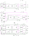
图10中的(A)、(B)、(C)分别示出光伏面板100和优化器200的三种连接方式,其中(A)为单路输入单路输出类型,(B)为两路输入单路输出类型,两路输入在内部并联作为优化器200的输入,(C)为两路输入两路输出类型,两路输出在优化器200内部并联后作为其输出。优化器200的每路输入分别包括正电压输入Input+和负电压输入Input-,而其输出则分别包括正输出母线bus+和负输出母线bus-。其中优化器200的电路结构和控制方式如图1-9所述,在此不再详述。(A), (B), and (C) in Fig. 10 show three connection modes of the
图1-9的优化器应用于光伏发电系统时,可采用优化器并联的结构。现在将结合附图11和12介绍用于光伏发电系统的优化器并联结构。When the optimizer shown in Figure 1-9 is applied to a photovoltaic power generation system, a structure in which the optimizers are connected in parallel can be used. The parallel structure of optimizers for photovoltaic power generation systems will now be described with reference to Figures 11 and 12 .
图11中示出多个优化器200并联的结构。每个优化器200对应一个光伏面板100。数个优化器200并联后得到直流高压,作为逆变器300的输入,并通过逆变器300转换为需要的交流电能。根据用户需求功率不同,可以灵活并联入数个优化器200。输出并联的优化器200在遇到光伏面板100部分遮挡的情况下,能够通过母线电压检测异常而关断,不会影响其他优化器200的工作,更不存在因故障而切出的优化器200依然通过电流的问题。FIG. 11 shows a structure in which
每个优化器200的输出分别连接到直流输出母线的正输出母线bus+和负输出母线bus-上。每个优化器200均具有第一正端子V1+、第二正端子V2+、第一负端子V1-和第二负端子V2-,第一正端子V1+连接直流输出母线的正输出母线bus+上,第一负端子V1-连接直流输出母线的负输出母线bus-上,第一正端子V1+在优化器200内部经由第二正端子V2+连接另一优化器200的第一正端子V1+,第一负端子V1-在优化器200内部经由第二负端子V2-连接另一优化器200的第一负端子V1-。The output of each
图12则示出另一种多个优化器200并联的结构。与图11不同的是,每个优化器200对应两个光伏面板100。根据实际需求,每个优化器200还可以对应更多个光伏面板100。对于此时的优化器200的输入输出结构,参见图10中的情况(B)或(C)的优化器200的输入输出结构。其优化器200的第一正端子V1+,第二正端子V2+,第一负端子V1-和第二负端子V2-与直流输出母线的正输出端子bus+和负输出端子bus-的连接方式与图11类似,在此不再详述。FIG. 12 shows another structure in which
通过本公开实施例的用于光伏逆变系统的优化器、优化器控制方法及其优化器并联结构,仅获取逆变器输出的直流母线电压,就可以控制优化器在MPPT模式、限功率模式和快速关闭模式之间切换,不需要在逆变器和优化器之间增加通讯线路,仅通过检测优化器的直流输出母线电压就可以完成优化器自身的工作模式切换,不影响其他优化器向逆变器输出功率。运用隔离型拓扑改善因光伏面板导致的共模漏电流问题,移相全桥LLC拓扑中所有功率器件均可实现软开关,效率高等优点。Through the optimizer for the photovoltaic inverter system, the optimizer control method and the parallel structure of the optimizer according to the embodiment of the present disclosure, only the DC bus voltage output by the inverter can be obtained, and the optimizer can be controlled in the MPPT mode and the limited power mode. Switching between the inverter and the fast shutdown mode does not need to add a communication line between the inverter and the optimizer. Only by detecting the DC output bus voltage of the optimizer can complete the switchover of the optimizer's own working mode, without affecting other optimizers to Inverter output power. The isolated topology is used to improve the common-mode leakage current problem caused by photovoltaic panels, and all power devices in the phase-shifted full-bridge LLC topology can realize soft switching and high efficiency.
本公开已由上述相关实施例加以描述,然而上述实施例仅为实施本公开的范例。必需指出的是,已揭露的实施例并未限制本公开的范围。相反,在不脱离本公开的精神和范围内所作的变动与润饰,均属本公开的专利保护范围。The present disclosure has been described by the above-mentioned related embodiments, but the above-mentioned embodiments are only examples for implementing the present disclosure. It must be pointed out that the disclosed embodiments do not limit the scope of the present disclosure. On the contrary, changes and modifications made without departing from the spirit and scope of the present disclosure all belong to the patent protection scope of the present disclosure.
Claims (15)
Priority Applications (2)
| Application Number | Priority Date | Filing Date | Title |
|---|---|---|---|
| CN201810367504.5A CN110391671B (en) | 2018-04-23 | 2018-04-23 | Optimizer, control method and parallel structure for photovoltaic inverter system |
| US16/361,840 US11005268B2 (en) | 2018-04-23 | 2019-03-22 | Optimizer, control method and parallel arrangement for photovoltaic system |
Applications Claiming Priority (1)
| Application Number | Priority Date | Filing Date | Title |
|---|---|---|---|
| CN201810367504.5A CN110391671B (en) | 2018-04-23 | 2018-04-23 | Optimizer, control method and parallel structure for photovoltaic inverter system |
Publications (2)
| Publication Number | Publication Date |
|---|---|
| CN110391671A CN110391671A (en) | 2019-10-29 |
| CN110391671B true CN110391671B (en) | 2023-03-10 |
Family
ID=68238256
Family Applications (1)
| Application Number | Title | Priority Date | Filing Date |
|---|---|---|---|
| CN201810367504.5A Active CN110391671B (en) | 2018-04-23 | 2018-04-23 | Optimizer, control method and parallel structure for photovoltaic inverter system |
Country Status (2)
| Country | Link |
|---|---|
| US (1) | US11005268B2 (en) |
| CN (1) | CN110391671B (en) |
Families Citing this family (15)
| Publication number | Priority date | Publication date | Assignee | Title |
|---|---|---|---|---|
| CN109193610B (en) * | 2018-09-28 | 2021-01-08 | 阳光电源股份有限公司 | Shutdown control system and method |
| CN110957760B (en) | 2019-11-27 | 2022-08-26 | 华为数字能源技术有限公司 | Photovoltaic system, optimizer and working state adjusting method of optimizer |
| EP3846337B1 (en) * | 2019-12-30 | 2025-09-10 | Solaredge Technologies Ltd. | Energy harvesting and electrical power generation |
| CN111756072B (en) * | 2020-07-30 | 2022-04-08 | 阳光电源股份有限公司 | Control method and operation control method of MLPE equipment and photovoltaic system |
| CN114123735B (en) * | 2020-08-31 | 2024-05-03 | 华为数字能源技术有限公司 | Series-parallel converter protection system, controller and converter |
| CN112600249B (en) * | 2021-01-05 | 2023-09-19 | 国网河南省电力公司平顶山供电公司 | Multi-mode control method for photovoltaic grid-connected inverter system that can include energy storage |
| CN114865583A (en) * | 2021-02-04 | 2022-08-05 | 广州中旭新能源有限公司 | Power optimization device capable of overcurrent protection, photovoltaic power generation system and control method thereof |
| CN114977266A (en) * | 2021-02-23 | 2022-08-30 | 华为数字能源技术有限公司 | Power conversion module and power supply system |
| US11799382B2 (en) * | 2021-03-03 | 2023-10-24 | Semiconductor Components Industries, Llc | Resonant converter with dual-mode control |
| CN113488982B (en) * | 2021-06-13 | 2023-03-14 | 浙江大学 | Communication-free working mode selection method applied to series photovoltaic power optimizer |
| WO2023164209A2 (en) * | 2022-02-28 | 2023-08-31 | Lunar Energy, Inc. | Rapid shutdown |
| US11670945B1 (en) | 2022-02-28 | 2023-06-06 | Lunar Energy, Inc. | Power optimizers in series with voltage sensors and a common reference signal |
| CN115664173A (en) * | 2022-11-11 | 2023-01-31 | 深圳市永航新能源技术有限公司 | A phase-shifted full-bridge conversion circuit control system |
| CN116774769A (en) * | 2023-08-23 | 2023-09-19 | 江苏纳通能源技术有限公司 | MPPT (maximum Power Point tracking) fast high-precision power control method, system, equipment and medium |
| CN119906099B (en) * | 2025-01-27 | 2025-12-02 | 中国矿业大学 | A method for controlling the output voltage, current, and power of photovoltaic systems. |
Citations (4)
| Publication number | Priority date | Publication date | Assignee | Title |
|---|---|---|---|---|
| CN202856652U (en) * | 2012-09-28 | 2013-04-03 | 深圳市天源新能源有限公司 | Photovoltaic pumping inverter and photovoltaic pumping system |
| CN203326921U (en) * | 2012-06-14 | 2013-12-04 | 江南大学 | Novel-type photovoltaic power optimizer |
| CN107154780A (en) * | 2017-06-08 | 2017-09-12 | 阳光电源股份有限公司 | A kind of photovoltaic generating system and its Poewr control method and power optimization device |
| CN107453403A (en) * | 2017-09-30 | 2017-12-08 | 阳光电源股份有限公司 | A kind of photovoltaic generating system and its control method |
Family Cites Families (12)
| Publication number | Priority date | Publication date | Assignee | Title |
|---|---|---|---|---|
| US9225285B2 (en) * | 2008-09-24 | 2015-12-29 | Sunpower Corporation | Photovoltaic installation with automatic disconnect device |
| US8648497B2 (en) * | 2009-01-30 | 2014-02-11 | Renewable Power Conversion, Inc. | Photovoltaic power plant with distributed DC-to-DC power converters |
| US9184594B2 (en) * | 2011-06-03 | 2015-11-10 | Schneider Electric Solar Inverters Usa, Inc. | Photovoltaic voltage regulation |
| DE102013101314A1 (en) * | 2013-02-11 | 2014-08-14 | Phoenix Contact Gmbh & Co. Kg | Safe photovoltaic system |
| US9602025B2 (en) * | 2013-07-12 | 2017-03-21 | Infineon Technologies Austria Ag | Multiphase power converter circuit and method |
| CN104079001B (en) | 2014-07-15 | 2017-08-25 | 浙江昱能科技有限公司 | To the control method of optimizer in photovoltaic parallel in system based on tandem type optimizer |
| JP6952245B2 (en) * | 2016-09-30 | 2021-10-20 | パナソニックIpマネジメント株式会社 | Power conversion system |
| CN106300433B (en) * | 2016-11-10 | 2019-08-13 | 阳光电源股份有限公司 | Coordinated control method and device for photovoltaic optimizer and photovoltaic inverter |
| CZ2017200A3 (en) * | 2017-04-10 | 2018-04-04 | Česká energeticko-auditorská společnost, s. r. o. | A device for optimizing the production, consumption and storage of electricity |
| CN106992550B (en) * | 2017-05-26 | 2021-04-13 | 阳光电源股份有限公司 | A control device and combiner box |
| CN106992554B (en) | 2017-06-08 | 2020-02-11 | 合肥阳光智维科技有限公司 | Optimizer control method, coordination control method, device and system |
| US10673246B2 (en) * | 2017-11-13 | 2020-06-02 | Futurewei Technologies, Inc. | System and device for exporting power, and method of configuring thereof |
-
2018
- 2018-04-23 CN CN201810367504.5A patent/CN110391671B/en active Active
-
2019
- 2019-03-22 US US16/361,840 patent/US11005268B2/en active Active
Patent Citations (4)
| Publication number | Priority date | Publication date | Assignee | Title |
|---|---|---|---|---|
| CN203326921U (en) * | 2012-06-14 | 2013-12-04 | 江南大学 | Novel-type photovoltaic power optimizer |
| CN202856652U (en) * | 2012-09-28 | 2013-04-03 | 深圳市天源新能源有限公司 | Photovoltaic pumping inverter and photovoltaic pumping system |
| CN107154780A (en) * | 2017-06-08 | 2017-09-12 | 阳光电源股份有限公司 | A kind of photovoltaic generating system and its Poewr control method and power optimization device |
| CN107453403A (en) * | 2017-09-30 | 2017-12-08 | 阳光电源股份有限公司 | A kind of photovoltaic generating system and its control method |
Also Published As
| Publication number | Publication date |
|---|---|
| CN110391671A (en) | 2019-10-29 |
| US20190326758A1 (en) | 2019-10-24 |
| US11005268B2 (en) | 2021-05-11 |
Similar Documents
| Publication | Publication Date | Title |
|---|---|---|
| CN110391671B (en) | Optimizer, control method and parallel structure for photovoltaic inverter system | |
| EP3055916B1 (en) | Smart grid power converter | |
| US7193872B2 (en) | Solar array inverter with maximum power tracking | |
| CN201336757Y (en) | Multi-way constant-current power supply used for high-power LED light source | |
| CN105141135B (en) | The control method of multi-channel parallel full-bridge LLC converters in a kind of cascading power source system | |
| US20120230066A1 (en) | Photovoltaic powered system | |
| CN102780221A (en) | System and method for controlling online type photovoltaic power generation microgrid without storage device | |
| CN101951011A (en) | Solar photovoltaic and commercial power combined power supply system and control method thereof | |
| CN110190751A (en) | A constant gain bidirectional DC-DC resonant converter and its control method | |
| CN104393767B (en) | Double active bridge circuit based dual-mode current-current converter and control device thereof | |
| CN103888013B (en) | The Miniature inverter theoretical based on high-frequency ac blood pressure lowering and numerical control device thereof | |
| Sun et al. | Adaptive dead-time modulation scheme for bidirectional LLC resonant converter in energy router | |
| Zeng et al. | A soft-switched four-port DC-DC converter for renewable energy integration | |
| Zhang et al. | An optimal control method for grid-connected photovoltaic micro-inverter to improve the efficiency at light-load condition | |
| CN118920536A (en) | Bidirectional energy storage inverter | |
| CN102332841B (en) | Control method of flyback photovoltaic grid-connected micro inverter under peak current control | |
| CN103701329A (en) | Solar photovoltaic converter of phase-shifted full-bridge soft switch | |
| Al Mamun et al. | A Grid-Tie Microinverter Design Based on Dual-Switch Flyback Topology for Solar PV Application | |
| Tao et al. | Grid-connected micro solar inverter implement using a c2000 mcu | |
| CN111030466B (en) | Wide-voltage isolation type DC-DC converter with automatic current limiting function | |
| KR102363847B1 (en) | Power optimizer, and its method of control method of pv grid connected system using thereof | |
| Mo et al. | Research on a non-complementary active clamp flyback converter with unfolding DC-AC inverter for decentralized grid-connected PV systems | |
| Yadav et al. | Maximum power point tracking algorithm for step-up/down partial power converters with improved performance around zero partiality | |
| CN202309559U (en) | Photovoltaic grid-connected inverter device | |
| Gao et al. | Performance evaluation of a non-isolated three-port converter for PV-battery hybrid energy system |
Legal Events
| Date | Code | Title | Description |
|---|---|---|---|
| PB01 | Publication | ||
| PB01 | Publication | ||
| SE01 | Entry into force of request for substantive examination | ||
| SE01 | Entry into force of request for substantive examination | ||
| GR01 | Patent grant | ||
| GR01 | Patent grant | ||
| TG01 | Patent term adjustment | ||
| TG01 | Patent term adjustment |