CN110226150B - controller - Google Patents
controller Download PDFInfo
- Publication number
- CN110226150B CN110226150B CN201780082223.9A CN201780082223A CN110226150B CN 110226150 B CN110226150 B CN 110226150B CN 201780082223 A CN201780082223 A CN 201780082223A CN 110226150 B CN110226150 B CN 110226150B
- Authority
- CN
- China
- Prior art keywords
- controller
- chassis
- operation button
- operating member
- elastic
- Prior art date
- Legal status (The legal status is an assumption and is not a legal conclusion. Google has not performed a legal analysis and makes no representation as to the accuracy of the status listed.)
- Active
Links
Images


Classifications
-
- A—HUMAN NECESSITIES
- A63—SPORTS; GAMES; AMUSEMENTS
- A63F—CARD, BOARD, OR ROULETTE GAMES; INDOOR GAMES USING SMALL MOVING PLAYING BODIES; VIDEO GAMES; GAMES NOT OTHERWISE PROVIDED FOR
- A63F13/00—Video games, i.e. games using an electronically generated display having two or more dimensions
- A63F13/20—Input arrangements for video game devices
- A63F13/24—Constructional details thereof, e.g. game controllers with detachable joystick handles
-
- A—HUMAN NECESSITIES
- A63—SPORTS; GAMES; AMUSEMENTS
- A63F—CARD, BOARD, OR ROULETTE GAMES; INDOOR GAMES USING SMALL MOVING PLAYING BODIES; VIDEO GAMES; GAMES NOT OTHERWISE PROVIDED FOR
- A63F13/00—Video games, i.e. games using an electronically generated display having two or more dimensions
- A63F13/20—Input arrangements for video game devices
- A63F13/21—Input arrangements for video game devices characterised by their sensors, purposes or types
- A63F13/211—Input arrangements for video game devices characterised by their sensors, purposes or types using inertial sensors, e.g. accelerometers or gyroscopes
-
- A—HUMAN NECESSITIES
- A63—SPORTS; GAMES; AMUSEMENTS
- A63F—CARD, BOARD, OR ROULETTE GAMES; INDOOR GAMES USING SMALL MOVING PLAYING BODIES; VIDEO GAMES; GAMES NOT OTHERWISE PROVIDED FOR
- A63F13/00—Video games, i.e. games using an electronically generated display having two or more dimensions
- A63F13/20—Input arrangements for video game devices
- A63F13/21—Input arrangements for video game devices characterised by their sensors, purposes or types
- A63F13/218—Input arrangements for video game devices characterised by their sensors, purposes or types using pressure sensors, e.g. generating a signal proportional to the pressure applied by the player
-
- A—HUMAN NECESSITIES
- A63—SPORTS; GAMES; AMUSEMENTS
- A63F—CARD, BOARD, OR ROULETTE GAMES; INDOOR GAMES USING SMALL MOVING PLAYING BODIES; VIDEO GAMES; GAMES NOT OTHERWISE PROVIDED FOR
- A63F13/00—Video games, i.e. games using an electronically generated display having two or more dimensions
- A63F13/20—Input arrangements for video game devices
- A63F13/23—Input arrangements for video game devices for interfacing with the game device, e.g. specific interfaces between game controller and console
- A63F13/235—Input arrangements for video game devices for interfacing with the game device, e.g. specific interfaces between game controller and console using a wireless connection, e.g. infrared or piconet
-
- G—PHYSICS
- G06—COMPUTING OR CALCULATING; COUNTING
- G06F—ELECTRIC DIGITAL DATA PROCESSING
- G06F3/00—Input arrangements for transferring data to be processed into a form capable of being handled by the computer; Output arrangements for transferring data from processing unit to output unit, e.g. interface arrangements
- G06F3/01—Input arrangements or combined input and output arrangements for interaction between user and computer
- G06F3/011—Arrangements for interaction with the human body, e.g. for user immersion in virtual reality
- G06F3/014—Hand-worn input/output arrangements, e.g. data gloves
-
- G—PHYSICS
- G06—COMPUTING OR CALCULATING; COUNTING
- G06F—ELECTRIC DIGITAL DATA PROCESSING
- G06F3/00—Input arrangements for transferring data to be processed into a form capable of being handled by the computer; Output arrangements for transferring data from processing unit to output unit, e.g. interface arrangements
- G06F3/01—Input arrangements or combined input and output arrangements for interaction between user and computer
- G06F3/02—Input arrangements using manually operated switches, e.g. using keyboards or dials
-
- G—PHYSICS
- G06—COMPUTING OR CALCULATING; COUNTING
- G06F—ELECTRIC DIGITAL DATA PROCESSING
- G06F3/00—Input arrangements for transferring data to be processed into a form capable of being handled by the computer; Output arrangements for transferring data from processing unit to output unit, e.g. interface arrangements
- G06F3/01—Input arrangements or combined input and output arrangements for interaction between user and computer
- G06F3/03—Arrangements for converting the position or the displacement of a member into a coded form
- G06F3/033—Pointing devices displaced or positioned by the user, e.g. mice, trackballs, pens or joysticks; Accessories therefor
- G06F3/0362—Pointing devices displaced or positioned by the user, e.g. mice, trackballs, pens or joysticks; Accessories therefor with detection of 1D translations or rotations of an operating part of the device, e.g. scroll wheels, sliders, knobs, rollers or belts
-
- G—PHYSICS
- G06—COMPUTING OR CALCULATING; COUNTING
- G06F—ELECTRIC DIGITAL DATA PROCESSING
- G06F2203/00—Indexing scheme relating to G06F3/00 - G06F3/048
- G06F2203/033—Indexing scheme relating to G06F3/033
- G06F2203/0331—Finger worn pointing device
Landscapes
- Engineering & Computer Science (AREA)
- Multimedia (AREA)
- Human Computer Interaction (AREA)
- General Engineering & Computer Science (AREA)
- Theoretical Computer Science (AREA)
- Physics & Mathematics (AREA)
- General Physics & Mathematics (AREA)
- Computer Networks & Wireless Communication (AREA)
- Position Input By Displaying (AREA)
- User Interface Of Digital Computer (AREA)
- Mechanical Control Devices (AREA)
Abstract
[问题]提出了一种控制器,其能够在保持操作构件的可操作性的同时抑制操作构件从底架的外表面突出的量。[方案]控制器具有:外壳和操作构件,操作构件能够以预定位置作为基准沿着外壳的延伸方向滑动,并且能够以预定位置作为基准在外壳的圆周方向上旋转,并且其至少一部分装配到设置在外壳的外表面中的凹陷部分中。
[Problem] There is proposed a controller capable of suppressing the amount by which the operating member protrudes from the outer surface of the chassis while maintaining the operability of the operating member. [Scenario] The controller has a housing and an operating member that is slidable in the extending direction of the housing with a predetermined position as a reference and rotatable in the circumferential direction of the housing with a predetermined position as a reference, and at least a part of which is fitted to the setting in a recessed portion in the outer surface of the housing.
Description
技术领域technical field
本公开涉及控制器。The present disclosure relates to controllers.
背景技术Background technique
迄今为止,已经开发了用于操纵设备操作的各种控制器,例如游戏控制台。To date, various controllers have been developed for manipulating the operation of devices, such as game consoles.
例如,专利文献1公开了一种内容再现装置,其中能够执行沿底架的轴向方向的滑动操作和沿底架的外圆周方向的旋转操作的操作元件安装在底架内。For example, Patent Document 1 discloses a content reproduction apparatus in which an operating member capable of performing a sliding operation in the axial direction of the chassis and a rotating operation in the outer circumferential direction of the chassis is installed in the chassis.
引文列表Citation List
专利文献Patent Literature
专利文献1:Patent Document 1:
日本专利公开No.2009-176308Japanese Patent Publication No. 2009-176308
发明内容SUMMARY OF THE INVENTION
技术问题technical problem
然而,在专利文献1中描述的内容再现装置中,操作元件安装在底架的外表面中的部分在底架的外周的长度上与未安装操作元件的部分的长度相同。因此,在感兴趣的内容再现装置中,操作元件很大程度地从底架的外表面突出。However, in the content reproduction apparatus described in Patent Document 1, the portion where the operating element is mounted in the outer surface of the chassis is the same length as the portion where the operating element is not mounted in the length of the outer circumference of the bottom chassis. Therefore, in the content reproduction apparatus of interest, the operating element protrudes from the outer surface of the chassis to a large extent.
然后,本公开提出了一种新颖且改进的控制器,其能够在保持操作构件的可操作性的同时抑制操作构件从底架的外表面突出的量。Then, the present disclosure proposes a novel and improved controller capable of suppressing the amount of protrusion of the operating member from the outer surface of the chassis while maintaining the operability of the operating member.
技术方案Technical solutions
根据本公开,提供了一种控制器,其包括底架和操作构件,所述操作构件能够以预定位置作为基准沿着底架的延伸方向滑动,并且能够以预定位置作为基准在底架的圆周方向上旋转,并且其至少一部分装配到设置在底架的外表面中的凹陷部分中。According to the present disclosure, there is provided a controller including a chassis and an operating member that is slidable along an extending direction of the chassis with a predetermined position as a reference, and is capable of being slid on the circumference of the chassis with a predetermined position as a reference is rotated in the direction of rotation, and at least a part thereof is fitted into a recessed portion provided in the outer surface of the chassis.
发明的有益效果Beneficial Effects of Invention
如到目前为止所描述的,根据本公开,可以在保持操作构件的可操作性的同时抑制从底架的外表面突出的量。应当注意,这里描述的效果决不是必然限制的,并且可以提供本公开中描述的任何效果。As described so far, according to the present disclosure, the amount of protrusion from the outer surface of the chassis can be suppressed while maintaining the operability of the operating member. It should be noted that the effects described here are by no means necessarily limiting, and any effects described in this disclosure may be provided.
附图说明Description of drawings
[图1][figure 1]
图1是示出了根据本公开的实施例的信息处理系统的构造的示例的示意图。FIG. 1 is a schematic diagram showing an example of the configuration of an information processing system according to an embodiment of the present disclosure.
[图2][figure 2]
图2是示出了已知控制器的问题的示意图。FIG. 2 is a schematic diagram illustrating a problem with a known controller.
[图3A][Figure 3A]
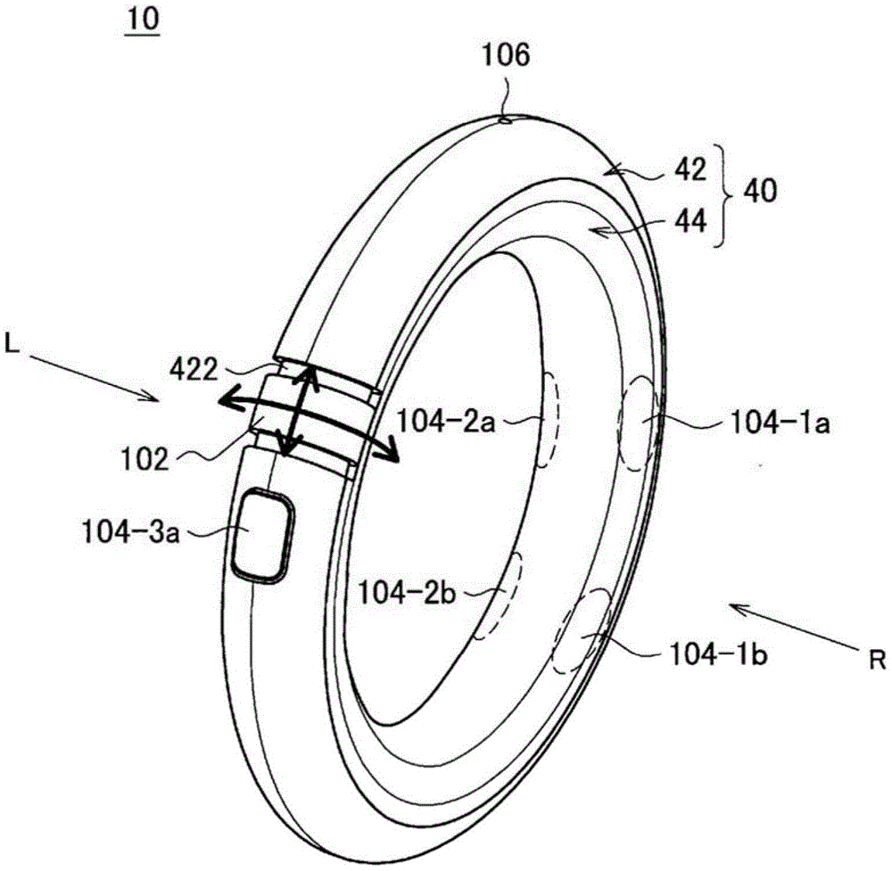
图3A是示出了根据实施例的控制器10的外观的视图。FIG. 3A is a view showing the appearance of the
[图3B][Figure 3B]
图3B是从图3A所示的“R”方向观察的控制器10的外观的视图。FIG. 3B is a view of the appearance of the
[图3C][Figure 3C]
图3C是从图3A所示的“L”方向观察的控制器10的外观的视图。FIG. 3C is a view of the external appearance of the
[图4][Figure 4]
图4是图3B中所示的微动拨盘102的圆周部分70的放大视图。FIG. 4 is an enlarged view of the
[图5][Figure 5]
图5是示出其中用一只手握持控制器10执行操作的场景的示例的视图。FIG. 5 is a view showing an example of a scene in which an operation is performed while holding the
[图6A][Fig. 6A]
图6A示出了控制器10放置在桌子上的状态下操作控制器10的场景的示例。FIG. 6A shows an example of a scene in which the
[图6B][Figure 6B]
图6B示出了用户将他/她的手臂穿过控制器10的中心处的开口以触摸另一物体的场景的示例。FIG. 6B shows an example of a scene in which the user passes his/her arm through the opening at the center of the
[图7A][Fig. 7A]
图7A是示出用户以使得微动拨盘102位于用户的左侧的方式水平地握持控制器10的场景的示例的视图。7A is a view showing an example of a scene in which the user holds the
[图7B][Figure 7B]
图7B是示出用户以使得微动拨盘102位于用户的右侧的方式水平地握持控制器10的场景的示例的视图。FIG. 7B is a view showing an example of a scene in which the user holds the
[图8A][Fig. 8A]
图8A是示出其中发光部分126设置在底架40的外表面上的预定位置的示例的视图。FIG. 8A is a view showing an example in which the
[图8B][Figure 8B]
图8B是示出其中发光部分126基本上设置在整个橡胶表面44上的示例的视图。FIG. 8B is a view showing an example in which the
[图9][Figure 9]
图9是示意性地示出了沿图3B中所示的线A-A截取的底架40的横截面的视图。FIG. 9 is a view schematically showing a cross section of the
[图10][Figure 10]
图10是示意性地示出了沿图3B中所示的线B-B截取的底架40的横截面的视图。FIG. 10 is a view schematically showing a cross section of the
[图11][Figure 11]
图11是示意性地示出了沿图3B中所示的线C-C截取的底架40的横截面的视图。FIG. 11 is a view schematically showing a cross section of the
[图12][Figure 12]
图12是示意性地示出了沿图3B中所示的线D-D截取的底架40的横截面的视图。FIG. 12 is a view schematically showing a cross section of the
[图13][Figure 13]
图13是示出控制器10的功能配置的示例的框图。FIG. 13 is a block diagram showing an example of the functional configuration of the
[图14][Figure 14]
图14是示出将控制器10和物体30彼此配对的方法的示例的视图。FIG. 14 is a view showing an example of a method of pairing the
[图15A][Fig. 15A]
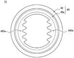
图15A示出了具有两个抓握区域480的橡胶表面46a安装到底架40的示例。FIG. 15A shows an example of the mounting of the
[图15B][Fig. 15B]
图15B示出了在其中心处具有抓握部分482的橡胶表面46b安装到底架40的示例。FIG. 15B shows an example in which the rubber surface 46b having the
[图15C][Fig. 15C]
图15C是示出了具有触发器484的橡胶表面46c安装到底架40的示例的视图。FIG. 15C is a view showing an example in which the
具体实施方式Detailed ways
在下文中,将参照附图详细描述本公开的优选实施例。应当注意,在本说明书和附图中,具有基本相同的功能配置的组成元件被赋予相同的附图标记,并且省略其重复描述。Hereinafter, preferred embodiments of the present disclosure will be described in detail with reference to the accompanying drawings. It should be noted that, in this specification and the drawings, constituent elements having substantially the same functional configuration are given the same reference numerals, and repeated descriptions thereof are omitted.
另外,在本说明书和附图中,在一些情况下,通过在相同的附图标记之后给出不同的字母,将具有基本相同的功能配置的多个组成元件彼此区分开。例如,如果需要,具有基本相同的功能配置的多个组成元件彼此区分,如控制器10a和控制器10b。应当注意,在具有基本相同的功能配置的多个组成元件不需要彼此特别区分的情况下,仅向这些组成元件添加相同的附图标记。例如,在控制器10a和控制器10b不需要彼此特别区分的情况下,控制器10a和控制器10b简称为控制器10。In addition, in this specification and the drawings, a plurality of constituent elements having substantially the same functional configuration are distinguished from each other by giving different letters after the same reference numerals in some cases. For example, if necessary, a plurality of constituent elements having substantially the same functional configuration are distinguished from each other, such as the controller 10a and the controller 10b. It should be noted that in the case where a plurality of constituent elements having substantially the same functional configuration do not need to be particularly distinguished from each other, only the same reference numerals are added to these constituent elements. For example, in the case where the controller 10a and the controller 10b do not need to be particularly distinguished from each other, the controller 10a and the controller 10b are simply referred to as the
另外,现在将根据以下项目顺序描述“具体实施方式”。In addition, the "detailed embodiment" will now be described according to the following item order.
1、信息处理系统的基本配置1. Basic configuration of information processing system
2、详细实施方式2. Detailed implementation
3、修改的示例3. Modified example
<<1.信息处理系统的基本配置>><<1. Basic configuration of information processing system>>
<1-1.基本配置><1-1. Basic configuration>
首先,将参考图1给出关于根据本公开的实施例的信息处理系统的基本配置的描述。如图1所示,根据该实施例的信息处理系统包括控制器10,控制装置20和物体30。First, a description will be given on a basic configuration of an information processing system according to an embodiment of the present disclosure with reference to FIG. 1 . As shown in FIG. 1 , the information processing system according to this embodiment includes a
{1-1-1.控制装置20}{1-1-1. Control device 20}
控制装置20是控制连接到控制装置20的设备(物体30等)的操作的装置。例如,控制装置20可以被配置为能够通过无线通信或有线通信与控制器10和物体30通信。在这种情况下,控制装置20从控制器10接收操作信号,并且基于接收的信号控制物体30的操作。The
应当注意,虽然图1示出了控制装置20和控制器10通过电缆22彼此连接的示例,但是本公开绝不限于这样的示例。电缆22可以不设置在控制装置20和控制器10之间,并且控制装置20和控制器10可以通过无线通信彼此通信。It should be noted that although FIG. 1 shows an example in which the
另外,控制装置20例如可以基于用户发出的指令执行预定应用程序(游戏应用程序等)。这里,预定应用程序可以存储在控制装置20中,可以存储在可以与控制装置20通信的外部装置(省略图示)中,或者可以记录在预定记录介质中,控制装置20可以从其中读取预定的应用程序。In addition, the
{1-1-2.物体30}{1-1-2.Object 30}
物体30是响应于从控制装置20接收的控制信号执行处理的设备。例如,物体30具有驱动部分并根据控制信号移动。或者,物体30具有显示部分,声音输出部分等,并且可以根据控制信号显示图像或输出声音。The
{1-1-3.控制器10}{1-1-3. Controller 10}
控制器10例如是用户利用其对物体30执行操作的装置。例如,控制器10和物体30可以彼此配对。在这种情况下,用户可以通过使用控制器10对与控制器10配对的物体30执行操作。应注意,稍后将描述用于配对的具体方法。The
<1-2.问题的安排><1-2. Arrangement of questions>
到目前为止已经描述了根据该实施例的信息处理系统的配置。现在,迄今为止,已经开发了用于诸如视频游戏控制台的电子设备的各种控制器。在这样的控制器中,例如,期望高可操作性,或者期望用户可以直观地操作这样的控制器。更具体地,期望可以实现以下四种操作方法。首先,希望用户能只用一只手操作控制器(“单手游戏”)。其次,希望在例如控制器放置在地板等上的情况下,用户可以在不握持控制器的情况下操作控制器(“无手游戏”)。第三,例如,甚至儿童也可以容易地抓握或释放控制器(“易于抓握/释放”)。第四,期望无论用户是惯用右手的人还是惯用左手的人,可操作性都不会改变(“惯用任一手”)。The configuration of the information processing system according to this embodiment has been described so far. Now, heretofore, various controllers have been developed for electronic devices such as video game consoles. In such a controller, for example, high operability is desired, or it is desired that a user can operate such a controller intuitively. More specifically, it is expected that the following four operation methods can be realized. First, the user is expected to be able to operate the controller with only one hand ("one-handed gaming"). Second, it is desirable that the user can operate the controller without holding the controller ("hands-free gaming") if the controller is placed on the floor or the like, for example. Third, for example, even children can easily grasp or release the controller ("easy grasp/release"). Fourth, it is expected that operability will not change whether the user is right-handed or left-handed ("either handed").
然而,利用已知的控制器,不可能或难以实现所有四种操作方法。图2是示出关于已知的典型两种控制器90的四种操作方法的实现是否可能的图。如图2所示,在“经典型”控制器90a中,在四种操作方法中,只能实现“手自由游戏”。However, with known controllers, it is impossible or difficult to implement all four methods of operation. FIG. 2 is a diagram showing whether the realization of the four operating methods with respect to the known typical two kinds of controllers 90 is possible. As shown in FIG. 2, in the "classic"
另外,在“棒型”控制器90b中,在四种操作方法中,可以实现“单手游戏”和“易于抓握/释放”。然而,在控制器90b例如放置在地板或桌子上的状态下,由于控制器90b不稳定,因此用户难以操作控制器90b。具体地说,用户难以进行“无手游戏”。另外,仅在用户垂直(或纵向)握持控制器90b的情况下才能实现“惯用任一手”。例如,在用户水平地(或横向地)握持控制器90b的情况下,用左手执行操作的情况和用右手执行操作的情况在可操作性上彼此差异很大。In addition, in the "stick type"
因此,已经以上述情况作为一个视点实现了根据本实施例的控制器10。控制器10可以具有环型底架40。利用这种形状,可以实现上述所有四种操作方法。Therefore, the
<<2.详细实施方式>><<2. Detailed implementation>>
<2-1.配置><2-1. Configuration>
{2-1-1.外观配置}{2-1-1. Appearance configuration}
{2-1-1-1.底架40){2-1-1-1. Bottom frame 40)
接下来,将详细描述根据本实施例的控制器10的配置。图3A至图3C是分别示出控制器10的外观配置的视图。如图3A所示,控制器10可以具有环型底架40。这里,如图3A所示,环型可以具有完全闭合的形状(换句话说,形状使得底架40的外周完全连续),或者可以具有底架40的一部分打开的形状(换句话说,例如,像字母“C”一样,底架40的外圆周的至少一部分是不连续的。另外,在环型形状中,底座40的外周和/或内周可以具有圆形,椭圆形或多边形(诸如四边形或三角形)。例如,如图3A所示,环型形状可以是甜甜圈形(花托形)。应当注意,在下文中,将集中描述底架40具有甜甜圈形的形状的示例。Next, the configuration of the
应当注意,在底架40的圆周方向上的圆周的一半的长度(在底架40具有甜甜圈形状的情况下沿着底架40的小圆的圆周的方向)可以等于或小于用户的手的长度(总之,长度等于或小于用户用一只手抓握的长度)。结果,如图5所示,用户可以仅用一只手抓握控制器10并且可以操作控制器10。总之,可以实现“单手游戏”。顺便提及,图5是示出通过使用控制器10执行物体30的操作的场景的示例的视图。另外,当用户用一只手操作控制器10时,例如,用户可以用另一只手触摸或移动另一物体(例如其他玩具)。It should be noted that the half length of the circumference in the circumferential direction of the bottom chassis 40 (the direction along the circumference of the small circle of the
另外,如图3B和3C所示,底架40的外表面可包括布置在底架40的外周侧上的树脂表面42,以及布置在底架40的内周侧上的橡胶表面44。这里,树脂表面42是本公开中的第一表面的示例。另外,橡胶表面44是本公开中的第二表面的示例。树脂表面42可包括比橡胶更硬的材料(例如丙烯腈-丁二烯-苯乙烯(ABS)树脂)。另外,橡胶表面44例如可以包括诸如硅橡胶的橡胶。应该注意,如稍后将参考图12描述的那样,包括在橡胶表面44中的固定按扣444固定到树脂表面42,从而使橡胶表面44能够固定到树脂表面42。In addition, as shown in FIGS. 3B and 3C , the outer surface of the
另外,在控制器10放置在其他物体的表面上的情况下,树脂表面42和橡胶表面44可以以使得橡胶表面44接触其他物体的表面的关系布置在底架40中。结果,在控制器10放置在其他物体的表面上的情况下,由于具有大摩擦系数的橡胶表面44接触其他物体的表面,所以当用户操作控制器10时,控制器10难以滑动,使得控制器10稳定。因此,例如,如图6A所示,在控制器10放置在地板等上的状态下,用户可以容易地操作控制器10。换句话说,可以实现“无手游戏”。顺便提及,图6A描绘了控制器10放置在桌子上的状态下,用户按下橡胶表面44,由此用户按下位于底架40内的两个内部操作按钮104-1(这将在后面描述)的场景的示例。In addition, in the case where the
另外,由于控制器10具有环型的形状,例如,如图6B所示,用户能够将他/她的手臂穿过控制器10的中心处的开口。在这种情况下,例如,在游戏应用程序的游戏期间,用户可以触摸或移动其他物体(诸如其他玩具)而无需将控制器10放置在地板上。In addition, since the
应当注意,如图3A所示,电缆22可以连接到其上的电缆连接传感器106可以设置在树脂表面42的预定位置处。如上所述,电缆22连接到电缆连接传感器106,从而使控制器10能够与控制装置20通信。另外,控制器10还可以以无线方式与控制装置20通信,而无需通过电缆22将控制装置20和控制器10彼此连接。It should be noted that, as shown in FIG. 3A , the
(2-1-1-2.微动拨盘102)(2-1-1-2. Jog dial 102)
另外,如图3A所示,微动拨盘102可以设置在底架40的外表面上。例如,如图3A所示,微动拨盘102可以设置在底架40的外表面上,使得微动拨盘102的至少一部分配合到设置在树脂表面42的预定位置处的凹陷部分422中。这里,微动拨盘102是本公开中的操作构件的示例。In addition, as shown in FIG. 3A , the
另外,如图3A中的彼此垂直的两个箭头所示,微动拨盘102可以以凹陷部分422中的预定位置作为基准沿着底座40的延伸方向滑动,并且可以以预定位置作为基准在底架40的圆周方向上旋转。这里,在底架40具有甜甜圈形的形状的情况下,延伸方向是沿着底架40的大圆的圆周的方向,并且圆周方向是沿着底架40的小圆的圆周的方向。In addition, as shown by two arrows perpendicular to each other in FIG. 3A , the
另外,虽然稍后将描述细节,但是控制器10还可以具有弹性构件600,该弹性构件600构造成使得在微动拨盘102从预定位置移动的情况下朝向预定位置的弹力被施加到微动拨盘102。结果,即使在用户在底架40的任何延伸方向上滑动微动拨盘102的情况下,例如,当用户从微动拨盘102释放他/她的手时,微动拨盘102也可以自动地返回到预定位置。另外,即使在用户在底架40的任何圆周方向上旋转微动拨盘102的情况下,例如,当用户从微动拨盘102释放他/她的手时,微动拨盘102也可以自动地返回到预定位置。In addition, although the details will be described later, the
另外,图3B是从图3A所示的箭头“R”方向观察的控制器10的外观的视图。另外,图3C是从图3A所示的箭头“L”方向(具体地,与箭头“R”的方向相反的方向)观察的控制器10的外观的视图。如图3B和3C所示,树脂表面42和橡胶表面44可以以底架40内预定表面作为基准具有基本对称的形状。这里,预定表面可以是与底架40的延伸方向平行并且沿着底架40的圆周方向穿过底架40的横截面的中心的表面。另外,微动拨盘102的外表面也可以以预定表面作为基准具有基本对称的形状。结果,例如,在用户水平地握持控制器10的情况下(具体地,在用户握持控制器10使得控制器10的中心处的开口面向用户的情况下),微动拨盘102位于用户左侧的情况(如图7A所示)以及微动拨盘102位于用户右侧的情况(如图7B所示)在指向微动拨盘102的用户侧的部分的面积和形状上彼此基本相同。因此,可以预期在用右手操作微动拨盘102的情况和用左手操作微动拨盘102的情况之间可操作性不会改变。换句话说,可以实现“惯用任一手”。In addition, FIG. 3B is a view of the appearance of the
另外,图4是图3B中所示的微动拨盘102的圆周部分70的放大视图。如图4所示,微动拨盘102从凹陷部分422突出的量(例如,图4中所示的距离d1)可以与凹陷部分422距树脂表面42的深度基本相同(例如,图4所示的距离d2)。结果,底架40的表面和微动拨盘102的外表面给出了好像它们是连续的外观,并且设计成使得控制器10形成整体的圆形(甜甜圈形)形状。因此,整个控制器10的外观变得优异。应注意,稍后将描述微动拨盘102的详细配置。In addition, FIG. 4 is an enlarged view of the
(2-1-1-3.外部操作按钮104-3)(2-1-1-3. External operation button 104-3)
另外,如图3B和3C所示,外部操作按钮104-3可以设置在底架40的外表面上。例如,如图3B和3C所示,外部操作按钮104-3a可以设置在底架40的外周侧(具体地,在树脂表面42侧),并且外部操作按钮104-3b可以设置在底架40的内周侧(具体地,在橡胶表面44侧)。In addition, as shown in FIGS. 3B and 3C , external operation buttons 104 - 3 may be provided on the outer surface of the
这里,外部操作按钮104-3a可以装配到设置在树脂表面42中的开口(省略图示)中以设置在底架40中。例如,外部操作按钮104-3a装配到开口中,使得外部操作按钮104-3a的外表面的高度变得与树脂表面42的高度基本相同。Here, the external operation button 104 - 3 a may be fitted into an opening (illustration omitted) provided in the
应注意,外部操作按钮104-3a的数量和外部操作按钮104-3b的数量不受特别限制。例如,可以设置多个外部操作按钮104-3a或外部操作按钮104-3b,或者可以不设置外部操作按钮104-3a和外部操作按钮104-3b。另外,外部操作按钮104-3a和外部操作按钮104-3b的安装位置也没有特别限制。例如,外部操作按钮104-3b可以设置在底架40的圆周上的橡胶表面44侧的与微动拨盘102的位置对应的位置处。It should be noted that the number of external operation buttons 104-3a and the number of external operation buttons 104-3b are not particularly limited. For example, a plurality of external operation buttons 104-3a or external operation buttons 104-3b may be provided, or the external operation buttons 104-3a and the external operation buttons 104-3b may not be provided. Also, the installation positions of the external operation button 104-3a and the external operation button 104-3b are not particularly limited. For example, the external operation button 104 - 3 b may be provided at a position corresponding to the position of the
(2-1-1-4.内部操作按钮104-1,内部操作按钮104-2)(2-1-1-4. Internal operation button 104-1, internal operation button 104-2)
另外,如图3A至图3C中的单点划线所示,内部操作按钮104-1和内部操作按钮104-2可以设置在底架40内。例如,可以设置两个或更多个内部操作按钮104-1和两个或更多个内部操作按钮104-2。这里,内部操作按钮104-1的数量和内部操作按钮104-2的数量可以彼此相同。在这种情况下,多个内部操作按钮104-1中的每一个和多个内部操作按钮104-2中的任何一个可以被布置为一对一地彼此对应。另外,感兴趣的内部操作按钮104-1中的每一个和与感兴趣的内部操作按钮104-1相对应的内部操作按钮104-2可以与相同的功能相关联。这里,内部操作按钮104-1是本公开中的第一操作按钮的示例,并且内部操作按钮104-2是本公开中的第二操作按钮的示例。In addition, as shown by the one-dot chain line in FIGS. 3A to 3C , the inner operation button 104 - 1 and the inner operation button 104 - 2 may be provided in the
另外,各个内部操作按钮104-1和各个内部操作按钮104-2基于压下橡胶表面44而接收操作。另外,如图3B和3C所示,各个内部操作按钮104-1和各个内部操作按钮104-2可以基本上设置在底架40的与橡胶表面44对应的内部区域中。如上所述,由于橡胶表面44由橡胶制成,因此用户压下橡胶表面44,从而能够容易地按压各个内部操作按钮104-1和各个内部操作按钮104-2。In addition, each of the internal operation buttons 104 - 1 and each of the internal operation buttons 104 - 2 receives operations based on depressing the
另外,多个内部操作按钮104-1中的每一个可以以上述预定表面作为基准(具体地,该表面平行于底架40的延伸方向并且沿着底架40的圆周方向穿过底架40的横截面的中心)设置在与对应于感兴趣的内部操作按钮104-1的内部操作按钮104-2基本对称的位置处。结果,例如,在用户水平握持控制器10的情况下,在微动拨盘102位于用户的左侧的情况下各个内部操作按钮104-1的位置(如图7A所示)和在微动拨盘102位于用户的右侧的情况下各个内部操作按钮104-2的位置(如图7B所示)彼此基本相同。因此,可以预期在用一只手(例如,用右手)操作各个内部操作按钮104-1的情况和用另一只手(例如,用左手)操作各个内部操作按钮104-2的情况之间可操作性不会改变(换句话说,可以实现“惯用任一手”)。In addition, each of the plurality of internal operation buttons 104 - 1 may be based on the above-mentioned predetermined surface (specifically, the surface is parallel to the extending direction of the
应当注意,尽管内部操作按钮104-1和内部操作按钮104-2通常由相同的数量设置,但具体数量决不是特别限制的。另外,内部操作按钮104-1和内部操作按钮104-2沿底架10的延伸方向的安装位置也没有特别限制。例如,在如图3B和3C所示的情况中,内部操作按钮104-1和内部操作按钮104-2两两设置,内部操作按钮104-1b可以以沿着底架40的圆周在作为基准的在微动拨盘102的外表面的中心位置处的横截面(例如,沿着图3B中所示的线B-B截取的底架40的横截面)作为基准设置在与内部操作按钮104-1a基本对称的位置。应该注意,这也适用于内部操作按钮104-2。It should be noted that although the internal operation buttons 104-1 and the internal operation buttons 104-2 are usually provided by the same number, the specific number is by no means particularly limited. In addition, the installation positions of the internal operation button 104 - 1 and the internal operation button 104 - 2 in the extending direction of the
应注意,稍后将描述内部操作按钮104-1和内部操作按钮104-2的详细配置。It should be noted that the detailed configuration of the internal operation button 104-1 and the internal operation button 104-2 will be described later.
(2-1-1-5.发光部分126)(2-1-1-5. Light-emitting portion 126)
另外,发光部分126还可以设置在底架40的外表面上。发光部分126例如可以包括全色发光二极管(LED),或者可以包括液晶显示器(LCD),有机发光二极管(OLED)等。In addition, the
例如,如图8A所示,至少一个发光部分126可以设置在底架40的外表面上的预定位置处。可替代地,如图8B所示,发光部分126可以基本上设置在整个橡胶表面44上,使得例如基本上可以在整个橡胶表面44上发光。For example, as shown in FIG. 8A , at least one
利用这样的配置,当例如在激活的游戏应用中产生各种事件时,可以使发光部分126以预定的发光模式发光。因此,可以在控制器10上表达事件的产生。With such a configuration, the light-emitting
{2-1-2.底架40的内部配置}{2-1-2. Internal configuration of chassis 40}
到目前为止已经描述了根据本实施例的控制器10的外部配置。接下来,将详细描述底架40的内部配置。在这种情况下,着重于微动拨盘102、内部操作按钮104-1和内部操作按钮104-2的配置给出描述。The external configuration of the
(2-1-2-1.微动拨盘102)(2-1-2-1. Jog dial 102)
首先,将参考图9和图10描述微动拨盘102的配置。图9是示意性地示出了沿图3B中所示的线A-A截取的底架40的横截面的视图。另外,图10是示意性地示出了沿图3B中所示的线B-B截取的底架40的横截面的视图。First, the configuration of the
如图9所示,例如,基板500可以沿着底架40的延伸方向布置在底架40内。然后,轴固定部分502可以固定在垂直于延伸方向的一个方向的一侧(例如,在图9中所示的上方向上)。另外,支撑轴504,拨盘环1022(包括在微动拨盘102中),两个滑动止动件506和两个弹性构件600可以固定到轴固定部分502的一个方向侧。As shown in FIG. 9 , for example, the
-弹性构件600-Elastic member 600
这里,如上所述,在微动拨盘102从预定位置移动的情况下,弹性构件600可以构造成将指向预定位置的弹力施加到微动拨盘102。更具体地,弹性构件600可包括:压缩弹簧6000,构造成在底架40的延伸方向上弹性变形;以及弹性结构6002,构造成在底架40的圆周方向上弹性变形。例如,弹性构件600是包括压缩弹簧6000和弹性结构6002的整体模制的弹簧。然而,本公开绝不限于这样的示例,并且压缩弹簧6000和弹性结构6002可以是分立的部件。这里,压缩弹簧6000是本公开中的第一弹性结构的示例,并且弹性结构6002是本公开中的第二弹性结构的示例。Here, as described above, in the case where the
--压缩弹簧6000--Compression spring 6000
例如,如图9所示,包括在各个弹性构件600中的压缩弹簧6000可以沿着底架40的延伸方向与两个滑动止动件506中的任何一个邻近地布置,并且可以固定到滑动止动件506。另外,压缩弹簧6000可以固定到轴固定部分502的一个方向侧。For example, as shown in FIG. 9 , the compression springs 6000 included in the respective elastic members 600 may be arranged adjacent to any one of the two sliding stoppers 506 along the extending direction of the
另外,如图9和10所示,微动拨盘102可包括拨盘环1022,两个滑动部分1026和两个连接部分1028。另外,拨盘环1022和两个滑动部分1026各自包括装配孔1024,并且支撑轴504可以插入穿过这些装配孔1024。另外,两个滑动部分1026的端部可以分别固定到邻近端部的滑动止动件506。Additionally, as shown in FIGS. 9 and 10 , the
利用这样的配置,当用户在底架40的延伸方向上沿第三方向(例如,在图9中所示的左方向上)滑动微动拨盘102时,滑动的力被传递到位于第三方向上的滑动止动件506a。结果,滑动止动件506a沿第三方向滑动,以压缩位于第三方向上的压缩弹簧6000a。然后,例如,当用户从微动拨盘102释放他/她的手时,压缩弹簧6000a向滑动止动件506a给出指向与第三方向相反的第四方向(例如,图9中所示的右方向)的弹力,使得滑动止动件506a移动直到它与止动肋420a接触。另外,固定到滑动止动件506a的(微动拨盘102的)滑动部分1026a响应于滑动止动件506a的移动而在第四方向上移动,使得微动拨盘102可以返回到初始位置。With such a configuration, when the user slides the
--弹性结构6002--Elastic structure 6002
另外,弹性结构6002可包括第一扭转弹簧6002a和第二扭转弹簧6002b。在这种情况下,第一扭转弹簧6002a在底架40的圆周方向上向微动拨盘102施加指向第一方向(例如,图10中所示的向下方向)的弹力。第二扭转弹簧6002b在圆周方向上向微动拨盘102施加与第一方向相反的第二方向(例如,图10中所示的向上方向)的弹力。或者,弹性结构6002可包括第一扭转弹簧6002a或第二扭转弹簧6002b中的一个。在这种情况下,例如,弹性构件600a可包括压缩弹簧6000a和第一扭转弹簧6002a,弹性构件600b可包括压缩弹簧6000b和第二扭转弹簧6002b。这里,第一扭转弹簧6002a是本公开中的第一弹性构件的示例,第二扭转弹簧6002b是本公开中的第二弹性构件的示例。Additionally, the elastic structure 6002 may include a
另外,如图10所示,第一扭转弹簧6002a可以设置成接触包括在微动拨盘102中的连接部分1028b。另外,第二扭转弹簧6002b可以设置成接触包括在微动拨盘102中的连接部分1028a。In addition, as shown in FIG. 10 , the
利用这样的配置,当用户在底架40的圆周方向上沿第二方向(例如,在图10中所示的向上方向上)旋转微动拨盘102时,旋转力通过连接部分1028b传递到第一扭转弹簧6002a。结果,第一扭转弹簧6002a响应于旋转量而变形。此后,例如,当用户从微动拨盘102释放他/她的手时,第一扭转弹簧6002a弹性变形,并且响应于当用户从微动拨盘102释放他/她的手时微动拨盘102的旋转量向微动拨盘102(更准确地说,连接部分1028b)施加弹力。结果,例如,微动拨盘102可以旋转直到连接部分1028a接触第二扭转弹簧6002b,从而返回到初始位置。With such a configuration, when the user rotates the
应注意,可以限制微动拨盘102的可旋转范围。例如,微动拨盘102可以在第二方向上旋转,直到包括在微动标度盘102中的连接部分1028a接触凹陷部分422的端部4220,或者直到包括在微动拨盘102中的第一端部1032a接触底架40的切口部分424a。换句话说,端部4220或切口部分424a可以起到阻止微动拨盘102沿第二方向旋转的止动件的作用。应注意,包括在微动拨盘102中的第二端部1034a的旋转轨道上没有布置物体(如图10所示)。因此,即使在微动拨盘102旋转时,第二端部1034a也不与其他物体接触。It should be noted that the rotatable range of the
同样,微动拨盘102可以在第一方向上旋转,直到包括在微动标度盘102中的连接部分1028b接触稍后将描述的元件支撑部分508的端部5080,或者直到包括在微动拨盘102中的第一端部1032b接触底架40的切口部分424b(省略图示)。换句话说,端部5080或切口部分424b可以起到阻止微动拨盘102沿第一方向旋转的止动件的作用。Likewise, the
-霍尔元件520-
另外,如图9所示,元件支撑部分508可以固定到与垂直于基板500的延伸方向的一个方向相反的方向(例如,图9中所示的向下方向)的一侧。然后,可以固定至少一个霍尔元件520,以便保持在基板500和元件支撑部分508之间。这里,霍尔元件520是本公开中的第二传感器的示例。霍尔元件520用作磁传感器。In addition, as shown in FIG. 9 , the
至少一个霍尔元件520可以感测微动拨盘102沿着底架40的延伸方向的滑动量,以及微动拨盘102在底架40的圆周方向上的旋转量。例如,如图9所示,微动拨盘102可以在与该一个方向相反的方向侧(例如,图9中所示的向下方向)上具有磁体1040。在这种情况下,霍尔元件520感测伴随磁体1040的位置变化的其周围磁通密度的变化,从而能够感测微动拨盘102的滑动量和微动拨盘102的旋转量。At least one
(2-1-2-2.内部操作按钮104-1,内部操作按钮104-2)(2-1-2-2. Internal operation button 104-1, internal operation button 104-2)
-构造-structure
接下来,将参考图11和图12详细描述内部操作按钮104-1和内部操作按钮104-2的构造。图11是示意性地示出了沿图3B中所示的线C-C截取的底架40的横截面的视图。另外,图12是示意性地示出了沿图3B中所示的线D-D截取的底架40的横截面的视图。Next, the configurations of the internal operation button 104-1 and the internal operation button 104-2 will be described in detail with reference to FIGS. 11 and 12 . FIG. 11 is a view schematically showing a cross section of the
如图11和12所示,例如,橡胶键450a或橡胶键450b可以在彼此相反的方向上设置在垂直于底架40的延伸方向的两个方向的相应侧上。例如,如图12所示,橡胶键450可以包括至少一个凸台4500,并且至少一个凸台4500可以各自轻压配合到设置在基板500中的孔中。结果,橡胶键450可以可靠地固定到基板500。As shown in FIGS. 11 and 12 , for example, the
另外,内部操作按钮104-1或内部操作按钮104-2中的一个可以设置在每个单独的橡胶键450中。另外,内部操作按钮104-2可以设置在相对于基板500(更准确地说,相对于平行于底架40的延伸方向,并沿着底架40的圆周方向穿过底架40的横截面的中心的表面)与内部操作按钮104-1基本对称的位置处。In addition, one of the internal operation button 104 - 1 or the internal operation button 104 - 2 may be provided in each individual rubber key 450 . In addition, the internal operation button 104 - 2 may be disposed at a position relative to the base plate 500 (more precisely, relative to an extension direction parallel to the
另外,如图11所示,仅在相对于与底架40的延伸方向垂直的方向的一个方向上可变形(可操作)的树脂键430可设置在底架40内。该“树脂键430”是具有键结构的部分,其通过将树脂喷射到用于注射模具的空腔中而模制,并且可以被视为与底架40一体模制。应注意,在初始状态下(具体地,在没有从外部施加力的状态下),树脂键430可以设置成不与橡胶键450接触。另外,如图11所示,树脂键430的作为最靠近橡胶表面44的表面的键顶442可以配置成圆顶形状。应注意,键顶442可以固定到橡胶表面44,或者可以与橡胶表面44分开。In addition, as shown in FIG. 11 , resin keys 430 that are deformable (operable) in only one direction with respect to the direction perpendicular to the extending direction of the
另外,如图12所示,在树脂键430的两侧(沿着底架40的延伸方向),橡胶键固定部分432和橡胶键固定部分434可以固定到橡胶表面44。在初始状态下(具体地,在没有从外部施加力的状态下),橡胶键固定部分432布置成使得橡胶键固定部分432的下端部分4320和下端部分4322与橡胶键450a之间的距离变得比预定距离短。应注意,这也适用于橡胶键固定部分434。结果,可以防止橡胶键450a浮动预定距离或更多,更具体地,防止橡胶键450a朝向橡胶表面44a移动预定距离或更多。In addition, as shown in FIG. 12 , on both sides of the resin key 430 (along the extending direction of the chassis 40 ), a rubber key fixing portion 432 and a rubber key fixing portion 434 may be fixed to the
-动作-action
根据上述构造,例如,如图11所示,当用户按下与内部操作按钮104-1的布置位置对应的橡胶表面44上的位置的圆周时,下压力被传递到树脂键430a,使树脂键430a朝向橡胶键450a移动。结果,树脂键430a的下端部分4300a或下端部分4300b向上移动到内部操作按钮104-1,从而使内部操作按钮104-1能够被按下。此后,例如,当用户从橡胶表面44释放他/她的手时,树脂键430a可以在与下压方向相反的方向上移动以返回到初始位置。According to the above configuration, for example, as shown in FIG. 11, when the user presses the circumference of the position on the
另外,如上所述,键顶442a可以配置成圆顶形状。因此,例如,如图11所示,不仅在用户从内部操作按钮104-1的正上方压下橡胶表面44a的情况下,而且在用户从内部操作按钮104-1的倾斜方向压下橡胶表面44a的情况下,压下力可以可靠地传递到树脂键430a。更具体地,由于可以按下内部操作按钮104-1的范围在橡胶表面44中具有给定的扩展,因此用户可以更容易地按下内部操作按钮104-1。In addition, as described above, the key tops 442a may be configured in a dome shape. Therefore, for example, as shown in FIG. 11, not only in the case where the user depresses the
{2-1-3.功能配置}{2-1-3. Function configuration}
到目前为止已经描述了底架40的内部配置。接下来,将详细描述控制器10的功能配置。图13是示出控制器10的功能配置的示例的框图。如图13所示,控制器10具有控制部分100,通信部分120,电力接收部分122,霍尔元件520,操作按钮104,传感器部分124,发光部分126和电池128。这里,操作按钮104是内部操作按钮104-1,内部操作按钮104-2和外部操作按钮104-3的总称。应注意,在下文中,将省略与上述描述重复的内容的描述。The internal configuration of the
(2-1-3-1.控制部分100)(2-1-3-1. Control section 100)
控制部分100例如可以包括诸如中央处理单元(CPU)的处理电路。控制部分100通常控制控制器10的操作。The
例如,控制部分100控制到控制装置20的信号传输。作为示例,控制部分100使通信部分120发送表示由霍尔元件520检测到的微动拨盘102的操作量的信号,以及表示操作按钮104的操作的检测结果的信号到控制装置20。For example, the
另外,控制部分100基于从外部装置(例如,控制装置20等)接收的信号来控制发光部分126的发光。另外,在通过稍后将描述的电力接收部分122从外部装置接收电力的情况下,控制部分100将如此接收的电力供应到电池128。In addition, the
(2-1-3-2.通信部分120)(2-1-3-2. Communication section 120)
这里,通信部分120是本公开中的接收部分的示例。通信部分120例如通过符合蓝牙(注册商标)低能量(BLE)等的无线通信或有线通信来执行向/从其他装置的信息的发送/接收。例如,通信部分120根据控制部分100的控制将表示用于微动拨盘102或操作按钮104的操作的检测结果的信号发送到控制装置20。另外,通信部分120从控制装置20接收响应于微动拨盘102或操作按钮104的操作内容的控制信号(例如,使发光部分126发光的控制信号等)。Here, the
(2-1-3-3.电力接收部分122)(2-1-3-3. Power receiving section 122)
电力接收部分122以非接触方式接收从外部装置(例如,托架等)供应的电力。例如,电力接收部分122可以是线圈,并且电力接收部分122可以沿着底架40的延伸方向缠绕在底架40内。应注意,由于底架40具有如上所述的环形形状,所以缠绕线圈可以容易地布置在底架40内。因此,可以尽可能地减小电力接收部分122的安装空间。The
(2-1-3-4.传感器部分124)(2-1-3-4. Sensor section 124)
传感器部分124是本公开中的第一传感器部分的示例。传感器部分124例如可以包括三轴加速度传感器,陀螺仪传感器等。传感器部分124可以感测控制器10的运动,姿势等。The
应注意,可以响应于传感器部分124的感测结果(例如,控制器的运动的感测结果等)通过例如控制装置20改变与各个内部操作按钮104-1和/或各个外部操作按钮104-3相关联的功能。It should be noted that the relationship with each of the internal operation buttons 104-1 and/or each of the external operation buttons 104-3 may be changed by, for example, the
(2-1-3-5.电池128)(2-1-3-5. Battery 128)
电池128例如可以是二次电池,例如锂离子二次电池。电池128例如根据控制部分100的控制存储由电力接收部122接收的电力(无线充电)。应注意,作为修改示例,电池128也可以是诸如干电池的主电池。The
应注意,其他组成元件的功能基本上类似于上述那些。It should be noted that the functions of other constituent elements are substantially similar to those described above.
(2-1-3-6.配对)(2-1-3-6. Pairing)
应注意,如上所述,作为控制器10的操作目标的物体30和控制器10可以彼此配对。这里,将描述配对控制器10和物体30的具体方法。例如,可以预先设置各个控制器10和各个物体30的配对,或者,例如,可以由用户在任意时刻指定配对。在后一种情况下,例如,如图14所示,希望与控制器10配对的物体30布置在控制器10的中心(具体地,在比底架40的内圆周更向内的开口中),从而使得能够通过例如使用以下两种方法建立配对。It should be noted that, as described above, the
这里,第一种方法是基于控制器10从物体30接收的信号的接收信号强度指示(RSSI)的值来建立配对的方法。具体地,首先,控制器10的传感器部分124测量从布置在控制器10的中心的物体30接收的信号的RSSI值。然后,控制部分100使通信部分120将RSSI的测量值发送到控制装置20。此后,控制装置20将RSSI的接收值与预定阈值进行比较。然后,仅在RSSI的值等于或大于预定阈值的情况下,控制装置20将控制器10和物体30彼此配对。Here, the first method is a method of establishing a pairing based on a value of a received signal strength indicator (RSSI) of a signal received by the
另外,第二种方法是通过控制器10和物体30之间的近场无线电通信(NFC)建立配对的方法。具体地,NFC的标签可以布置在物体30中。然后,仅在通过NFC在(通信部分120的)控制器10与物体30之间建立通信的情况下,控制器10和物体30可以彼此配对。In addition, the second method is a method of establishing pairing through Near Field Radio Communication (NFC) between the
<2-2.效果><2-2. Effects>
{2-2-1.效果1}{2-2-1. Effect 1}
如到目前为止已经描述的,根据本实施例的控制器10可以具有环形底架40。因此,例如,可以实现图2中所示的四种操作方法。例如,在用户水平握持控制器10的场景中,用户用右手操作控制器10的情况和用户用左手操作控制器10的情况在可操作性上基本上彼此相同。As has been described so far, the
{2-2-2.效果2}{2-2-2. Effect 2}
另外,控制器10具有的微动拨盘102可以以预定位置为基准沿底架40的延伸方向滑动,并且可以以预定位置为基准在底架40的圆周方向上旋转。因此,即使在用户以任意方式握持控制器10的情况下,例如,用一只手或两只手,用户也可以容易地操作微动拨盘102。In addition, the
另外,微动拨盘102可以设置在底架40的圆周方向上。因此,例如,即使当用户改变他/她握持控制器10的方式时,用户用右手操作微动拨盘102的情况和用户用左手操作微动拨盘102的情况在可操作性上基本上彼此相同。In addition, the
<<3.修改示例>><<3. Modified example>>
尽管到目前为止已经参考附图详细描述了本公开的优选实施例,但是本公开绝不限于这样的示例。显然,本公开所属技术领域的本领域技术人员可以在权利要求中描述的技术构思的范围内构思各种变化或修改,并且这些变化或修改自然地被认为与本公开的技术范围有关。例如,可以解决通过上述实施例要解决的问题的至少一部分的配置(通过本公开的修改示例)可以理解为与本公开的技术范围相关。Although the preferred embodiments of the present disclosure have been described in detail so far with reference to the accompanying drawings, the present disclosure is by no means limited to such examples. It is apparent that those skilled in the art to which the present disclosure pertains can conceive various changes or modifications within the scope of the technical idea described in the claims, and these changes or modifications are naturally considered to be related to the technical scope of the present disclosure. For example, configurations that can solve at least a part of the problems to be solved by the above-described embodiments (through modified examples of the present disclosure) can be understood as being related to the technical scope of the present disclosure.
<3-1.修改示例1>><3-1. Modification example 1>>
例如,尽管在上述实施例中主要描述了橡胶表面44固定到底架40的示例,但是本公开绝不限于这样的示例,并且橡胶表面44可以是可拆卸的。另外,在这种情况下,代替(标准)橡胶表面44,另一种橡胶表面46可以附接到底架40。For example, although the example in which the
例如,如图15A所示,在内圆周侧上具有两个抓握区域480的橡胶表面46a可以安装到底架40(而不是标准橡胶表面44)。结果,可以增强保持控制器10的容易性。For example, as shown in FIG. 15A, a
可替代地,如图15B所示,例如,在中心处具有圆柱形抓握部分482的橡胶表面46b可以安装到底架40(而不是标准橡胶表面44)。结果,用户不仅可以在圆周方向上抓握底架40,而且可以抓握抓握部分482。例如,用户握持抓握部分482,由此用户变得容易将控制器10像拳击一样推到用户面前,或者拉回控制器10。Alternatively, as shown in Figure 15B, for example, a rubber surface 46b having a
可替代地,如图15C所示,在内圆周侧上具有触发器484的橡胶表面46c可以安装到底架40(而不是标准橡胶表面44)。例如,橡胶表面46c可以安装到底架40,使得用户可以通过操作触发器484来按压外部操作按钮104-3b。结果,用户可以通过拉动触发器484来操作外部操作按钮104-3b。Alternatively, as shown in FIG. 15C, a
<3-2.修改示例2><3-2. Modification example 2>
另外,作为另一修改示例,每个发射可见光或红外光的多个发光部分126可以设置在控制器10中。然后,例如,控制装置20基于由设置在环境内的相机(省略图示)捕获的控制器10的图像来识别在拍摄时发光部分126的位置,从而使得控制器10的位置或姿势也能够被识别。结果,例如,即使在任意种类的游戏机,虚拟现实(VR)应用程序,增强现实(AR)应用程序等中,使用根据本实施例的控制器10的操作也变得可能。应注意,设置在头戴式显示器(HMD)中的相机可以用作设置在环境中的相机。在这种情况下,控制装置20可以与HMD一体地配置,并且控制器10优选地以无线方式连接到HMD。In addition, as another modified example, a plurality of
<3-3.修改示例3><3-3. Modified example 3>
另外,作为另一个修改示例,对应于手指的多个按钮(或压力传感器)可以设置在底架40的外表面上的与当用户抓握控制器10时用户的手指的相应位置对应的相应位置处。在这种情况下,例如,在可以与控制装置20通信的外部显示器上显示虚拟手的场景中,控制装置20可以能够基于检测到用户对多个按钮(或压力传感器)中的每一个的触摸操作的结果来改变虚拟手的手势。In addition, as another modified example, a plurality of buttons (or pressure sensors) corresponding to fingers may be provided on the outer surface of the
<3-4.修改示例4><3-4. Modified example 4>
应注意,由于控制器10的姿势在控制装置20和控制器10通过电缆22彼此连接的情况下受到限制,因此用户可以识别控制器10的上下方向(具体地,哪侧是“上”。另一方面,在控制装置20和控制器10没有通过电缆22彼此连接的情况下,担心用户不区分控制器10的上侧和下侧。然后,作为另一修改示例,可以在底架40的外表面的预定位置(例如,在外部操作按钮104-3a等中)打印徽标。结果,即使在控制装置20和控制器10没有通过电缆22彼此连接的情况下,也可以使用户识别上下方向。然后,可以引导用户以防止用户将控制器10倒置。It should be noted that since the posture of the
另外,相对于控制器10的垂直方向对称设置的两个内部操作按钮104-1(和两个内部操作按钮104-2)可以全部与相同的功能相关联。结果,即使在用户倒置控制器10的情况下,用户也可以类似于用户相对于垂直方向适当地保持控制器10的情况来操作控制器10。In addition, the two internal operation buttons 104-1 (and the two internal operation buttons 104-2) disposed symmetrically with respect to the vertical direction of the
<3-5.修改示例5><3-5. Modified example 5>
另外,作为另一修改示例,控制器10例如可以是可穿戴设备,诸如环型设备,手镯型设备或手表型设备。这里,环形装置和手镯型装置中的每一个不需要具有完美的圆形形状,并且只需具有可以插入用户的手指或手臂的形状。应当注意,如上所述,微动拨盘102的至少一部分可以配合到底架40的凹陷部分422中,并且从微动拨盘102的凹陷部分422突出的量可以基本上与凹陷部分422的距底座40的外表面的深度相同。因此,底座40的整个表面变得基本上连续,并且不会产生突起。因此,在控制器10用作可穿戴设备的情况下,佩戴感极佳,并且用户可以容易地操作例如微动拨盘102等。另外,由于作为可穿戴设备的控制器10意外掉落的概率基本上很小,因此作为可穿戴设备的控制器10也可以适当地用作用于手势输入的控制器或用于VR的控制器。In addition, as another modified example, the
<3-6.修改示例2,3和5的组合><3-6. Modify the combination of examples 2, 3 and 5>
另外,如上所述,作为修改示例5的可穿戴设备的控制器10可以适当地应用于上述修改示例2中描述的VR应用程序。由于在使用VR应用程序时用户可能无法直接在视觉上识别真实环境,所以当用户在真实空间中掉落控制器10时,他/她很难拿起掉落的控制器10。对于这样的问题,由于在作为可穿戴设备的控制器10中控制器10掉落的可能性基本上很小,因此可以省略安装防止跌落的带子等。顺便提及,从作为VR的控制器的可操作性的观点来看,作为可穿戴设备的控制器10优选地以环形设备的形式配置。通过在VR应用程序中采用这样的配置,用户还可以通过微动拨盘102执行更详细的输入操作,同时实现了控制器10的自然手势输入(修改示例3)和防止掉落(修改示例5)二者。另外,无论惯用右手的人还是惯用左手的人,作为环型设备的控制器10的可操作性不会改变。因此,使控制装置20识别用于右手的控制器10和用于左手的控制器10,使得用户可以利用用于右手的微动拨盘102和用于左手的微动拨盘102中的每一个进行独立的操作输入。In addition, as described above, the
另外,当将修改示例3的压力传感器应用于作为环型设备的控制器10时,即使要安装的控制器10的数量是一个,也可以输入多种手势(标记)。例如,在用户将控制器10安装到食指,用于控制器10的上部上的压力传感器与拇指之间的接触的情况下,可以在显示器上显示捏合手势。另外,对于控制器10的下部上的压力传感器与中指之间的接触,可以在显示器上显示竖起手势。另外,对于拇指和中指同时接触控制器10的上部上的压力传感器和控制器10的下部上的压力传感器,可以在显示器上显示抓握手势。以这种方式,通过在控制器10的上侧和下侧提供压力传感器,可以根据真实空间中的手势操作显示至少三种手势输入。当然,上述手势可以用其他操作输入代替。另外,压力传感器可以用能够检测其他手指的接触的传感器代替,或者可以用如上所述的按钮代替。另外,压力传感器设置在控制器10的上部或下部中的至少一个上是足够的。In addition, when the pressure sensor of Modified Example 3 is applied to the
在环形设备中,与微动拨盘102相对的一侧位于用户的手指基本上不接触的位置。因此,控制器10的电源开关优选地设置在控制器10的与微动拨盘102相对的一侧的外周表面上。另外,在压力传感器设置在控制器10的上侧和下侧并且如上所述执行手势的情况下,微动拨盘102不可避免地布置在压力传感器之间。在该配置中,首先,在拇指和中指接触的各个位置处限定压力传感器的布置,然后,根据在压力传感器之间限定的空间的尺寸来限定微动拨盘102的尺寸。In a ring device, the side opposite the
另外,本说明书中描述的效果仅是解释性或示例性的,而不是限制性的。换句话说,根据本公开的技术可以从本说明书的描述连同上述效果一起提供对于本领域技术人员显而易见的其他效果,或者代替上述效果。In addition, the effects described in this specification are only illustrative or exemplary, and not restrictive. In other words, the technology according to the present disclosure can provide other effects apparent to those skilled in the art from the description of this specification together with the above-described effects, or in place of the above-described effects.
应注意,以下配置也属于本公开的技术范围。It should be noted that the following configurations also belong to the technical scope of the present disclosure.
(1)(1)
一种控制器,包括:A controller comprising:
底架;以及chassis; and
操作构件,所述操作构件能够以预定位置作为基准沿着底架的延伸方向滑动,并且能够以预定位置作为基准在底架的圆周方向上旋转,并且其至少一部分装配到设置在底架的外表面中的凹陷部分中。An operating member that is slidable along the extending direction of the chassis with a predetermined position as a reference, and is rotatable in the circumferential direction of the chassis with a predetermined position as a reference, and at least a part of which is fitted to the outside provided on the chassis in depressions in the surface.
(2)(2)
根据上述(1)所述的控制器,还包括:The controller according to (1) above, further comprising:
弹性构件构造成在操作构件从预定位置移动的情况下向操作构件提供指向预定位置的弹力。The elastic member is configured to provide an elastic force directed to a predetermined position to the operating member when the operating member is moved from the predetermined position.
(3)(3)
根据上述(2)所述的控制器,According to the controller described in (2) above,
其中,所述弹性构件包括第一弹性结构和第二弹性结构,所述第一弹性结构构造成在延伸方向上弹性变形,所述第二弹性结构构造成在圆周方向上弹性变形。Wherein, the elastic member includes a first elastic structure and a second elastic structure, the first elastic structure is configured to elastically deform in an extension direction, and the second elastic structure is configured to elastically deform in a circumferential direction.
(4)(4)
根据上述(3)所述的控制器,According to the controller described in (3) above,
其中,所述弹性构件是包括第一弹性结构和第二弹性结构的一体成型的压缩弹簧。Wherein, the elastic member is an integrally formed compression spring including a first elastic structure and a second elastic structure.
(5)(5)
根据上述(3)或(4)所述的控制器,According to the controller described in (3) or (4) above,
其中,所述第二弹性结构包括第一弹性构件和第二弹性构件,所述第一弹性构件在圆周方向上向操作构件提供朝向第一方向的弹力,所述第二弹性构件在圆周方向上向操作构件提供朝向与第一方向相反的第二方向的弹力。Wherein, the second elastic structure includes a first elastic member and a second elastic member, the first elastic member provides elastic force towards the first direction to the operating member in the circumferential direction, and the second elastic member is in the circumferential direction The operating member is provided with an elastic force toward a second direction opposite to the first direction.
(6)(6)
根据上述(1)至(5)中任一项所述的控制器,The controller according to any one of (1) to (5) above,
其中,所述底架是环形的形状。Wherein, the base frame is annular in shape.
(7)(7)
根据上述(6)所述的控制器,还包括:The controller according to the above (6), further comprising:
第一操作按钮,其设置在底架内,并且基于压下底架的外表面来接收操作;和a first operation button disposed within the chassis and receiving an operation based on depressing an outer surface of the chassis; and
第二按钮,其设置在以底架内的预定表面作为基准的与第一操作按钮基本对称的位置,并且基于压下底架的外表面来接收操作,a second button that is disposed at a position substantially symmetrical to the first operation button with a predetermined surface inside the chassis as a reference, and receives an operation based on depressing the outer surface of the chassis,
其中,所述预定表面是平行于延伸方向并且沿着圆周方向穿过底架的横截面的大致中心的表面。Wherein, the predetermined surface is a surface parallel to the extending direction and passing through the substantially center of the cross-section of the chassis in the circumferential direction.
(8)(8)
根据上述(7)所述的控制器,According to the controller described in (7) above,
其中,控制器具有多个第一操作按钮和多个操作按钮,Wherein, the controller has a plurality of first operation buttons and a plurality of operation buttons,
多个第一操作按钮中的每一个一对一地对应于多个第二操作按钮中的任一个,并且each of the plurality of first operation buttons corresponds to any one of the plurality of second operation buttons on a one-to-one basis, and
多个第二操作按钮中的每一个,以及多个第一操作按钮中的与感兴趣的第二操作按钮相对应的第一操作按钮设置在以预定表面为基准的彼此基本对称的位置处。Each of the plurality of second operation buttons, and a first operation button corresponding to the second operation button of interest among the plurality of first operation buttons are disposed at positions substantially symmetrical to each other with reference to a predetermined surface.
(9)(9)
根据上述(7)或(8)所述的控制器,还包括:The controller according to (7) or (8) above, further comprising:
感测控制器运动的第一传感器部分,a first sensor portion that senses movement of the controller,
其中,响应于第一传感器部分的感测结果,改变与第一操作按钮和/或第二操作按钮相关联的功能。Wherein, the function associated with the first operation button and/or the second operation button is changed in response to the sensing result of the first sensor part.
(10)(10)
根据上述(7)至(9)中任一项所述的控制器,The controller according to any one of (7) to (9) above,
其中,底架的外表面包括:Among them, the outer surface of the chassis includes:
第一表面,其布置在第一底架的外圆周侧上,并由比橡胶更硬的材料制成;和a first surface disposed on the outer circumferential side of the first chassis and made of a material harder than rubber; and
第二表面,其布置在底架的内圆周侧上,并由橡胶制成。The second surface, which is arranged on the inner circumferential side of the chassis, is made of rubber.
(11)(11)
根据上述(10)所述的控制器,According to the controller described in (10) above,
其中,在控制器放置在其他物体的表面上的情况下,所述第二表面接触另一物体的表面。Wherein, when the controller is placed on the surface of the other object, the second surface contacts the surface of the other object.
(12)(12)
根据上述(10)或(11)所述的控制器,According to the controller described in (10) or (11) above,
其中,第一操作按钮和第二操作按钮分别布置在底架内对应于第二表面的区域中,并且Wherein, the first operation button and the second operation button are respectively arranged in the area of the chassis corresponding to the second surface, and
第一操作按钮和第二操作按钮均基于压下第二表面而接收操作。Both the first operation button and the second operation button receive an operation based on depressing the second surface.
(13)(13)
根据上述(10)至(12)中任一项所述的控制器,The controller according to any one of (10) to (12) above,
其中,所述第一表面和第二表面具有以预定表面作为基准的基本对称的形状。Wherein, the first surface and the second surface have substantially symmetrical shapes with a predetermined surface as a reference.
(14)(14)
根据上述(6)至(13)中任一项所述的控制器,The controller according to any one of (6) to (13) above,
其中,从操作构件的凹陷部分突出的量与凹陷部分的距底架的外表面的深度基本相同。Here, the amount protruding from the recessed portion of the operating member is substantially the same as the depth of the recessed portion from the outer surface of the chassis.
(15)(15)
根据上述(6)至(14)中任一项所述的控制器,The controller according to any one of (6) to (14) above,
其中,操作构件的外表面具有以底架内的预定表面为基准的基本对称的形状,并且wherein the outer surface of the operating member has a substantially symmetrical shape with respect to a predetermined surface within the chassis, and
所述预定表面是平行于延伸方向并且沿着圆周方向穿过底架的横截面的大致中心的表面。The predetermined surface is a surface parallel to the extending direction and passing through the substantially center of the cross-section of the chassis in the circumferential direction.
(16)(16)
根据上述(1)至(15)中任一项所述的控制器,还包括:The controller according to any one of (1) to (15) above, further comprising:
第二传感器部分,其感测操作构件沿延伸方向的滑动量,以及操作构件沿圆周方向的旋转量。The second sensor portion senses the sliding amount of the operating member in the extending direction and the rotation amount of the operating member in the circumferential direction.
(17)(17)
根据上述(16)所述的控制器,According to the controller described in (16) above,
其中,操作构件还具有磁体,并且wherein the operating member further has a magnet, and
所述第二传感器部分通过感测第二传感器部分周围的磁通量密度来感测操作构件的滑动量和操作构件的旋转量。The second sensor portion senses the sliding amount of the operating member and the rotation amount of the operating member by sensing the magnetic flux density around the second sensor portion.
(18)(18)
根据上述(1)至(17)中任一项所述的控制器,还包括:The controller according to any one of (1) to (17) above, further comprising:
设置在底架内的支撑轴,a support shaft arranged in the base frame,
其中,所述操作构件具有装配孔,并且wherein the operating member has a fitting hole, and
所述支撑轴插入穿过装配孔。The support shaft is inserted through the fitting hole.
(19)(19)
根据上述(1)至(18)中任一项所述的控制器,还包括:The controller according to any one of (1) to (18) above, further comprising:
接收部分,其从外部装置接收响应于操作构件的操作的信号;a receiving section that receives a signal from an external device in response to an operation of the operating member;
发光部分;和the light-emitting portion; and
控制部分,其使发光部分基于接收到的信号发光。A control section that causes the light-emitting section to emit light based on the received signal.
(20)(20)
根据上述(1)至(19)中任一项所述的控制器,还包括:The controller according to any one of (1) to (19) above, further comprising:
电力接收部分,其沿着延伸方向缠绕在底架内,并以非接触方式接收从外部装置供应的电力;和a power receiving portion that is wound within the chassis in an extending direction and receives power supplied from an external device in a non-contact manner; and
存储从电力接收部分接收的电力的电池。A battery that stores the power received from the power receiving section.
[附图标记列表][List of reference numerals]
10,90a,90b控制器10,90a,90b Controller
20控制装置20 Controls
30物体30 objects
40底架40 chassis
42树脂表面42 resin surface
44,46橡胶表面44,46 rubber surface
100控制部分100 Control Sections
102微动拨盘102 jog dial
104-1,104-2内部操作按钮104-1, 104-2 Internal operation buttons
104-3外部操作按钮104-3 External operation buttons
120通信部分120 Communications Section
122电力接收部分122 Power Receiving Section
124传感器部分124 sensor section
126发光部分126 luminous parts
128电池128 batteries
422凹陷部分422 recessed part
430树脂键430 resin bond
450橡胶键450 rubber keys
500基板500 substrates
504支撑轴504 support shaft
520霍尔元件520 Hall element
600弹性构件600 elastic members
1024装配孔1024 mounting holes
1040磁体1040 Magnet
6000压缩弹簧6000 Compression Spring
6002弹性结构6002 Elastic Structure
Claims (20)
Applications Claiming Priority (3)
| Application Number | Priority Date | Filing Date | Title |
|---|---|---|---|
| JP2017-002534 | 2017-01-11 | ||
| JP2017002534 | 2017-01-11 | ||
| PCT/JP2017/037443 WO2018131239A1 (en) | 2017-01-11 | 2017-10-17 | Controller |
Publications (2)
| Publication Number | Publication Date |
|---|---|
| CN110226150A CN110226150A (en) | 2019-09-10 |
| CN110226150B true CN110226150B (en) | 2022-09-27 |
Family
ID=62839649
Family Applications (1)
| Application Number | Title | Priority Date | Filing Date |
|---|---|---|---|
| CN201780082223.9A Active CN110226150B (en) | 2017-01-11 | 2017-10-17 | controller |
Country Status (5)
| Country | Link |
|---|---|
| US (2) | US11000760B2 (en) |
| EP (1) | EP3570139B1 (en) |
| JP (2) | JP6795623B2 (en) |
| CN (1) | CN110226150B (en) |
| WO (1) | WO2018131239A1 (en) |
Families Citing this family (13)
| Publication number | Priority date | Publication date | Assignee | Title |
|---|---|---|---|---|
| EP3207962B1 (en) | 2014-10-16 | 2024-12-18 | Nintendo Co., Ltd. | Training implement, training system, and input device |
| CN109432769B (en) * | 2018-12-14 | 2024-04-02 | 歌尔科技有限公司 | Operating handles for smart devices |
| WO2020129848A1 (en) * | 2018-12-19 | 2020-06-25 | 株式会社ソニー・インタラクティブエンタテインメント | Charging device, control device, and apparatus system |
| WO2020129812A1 (en) * | 2018-12-19 | 2020-06-25 | 株式会社ソニー・インタラクティブエンタテインメント | Input device |
| JP6666505B1 (en) | 2019-06-20 | 2020-03-13 | 任天堂株式会社 | Input device |
| JP6666504B1 (en) | 2019-06-20 | 2020-03-13 | 任天堂株式会社 | Device, system, game system, and device set |
| CN111450526B (en) * | 2019-06-20 | 2021-11-09 | 任天堂株式会社 | Device, system, game system and device group |
| JP6688424B1 (en) | 2019-08-30 | 2020-04-28 | 任天堂株式会社 | Information processing system, information processing program, information processing apparatus, and information processing method |
| JP6688425B1 (en) | 2019-08-30 | 2020-04-28 | 任天堂株式会社 | Information processing system, information processing program, information processing apparatus, and information processing method |
| US11556168B2 (en) * | 2021-01-11 | 2023-01-17 | Microsoft Technology Licensing, Llc | Multilayer controller |
| JP7730993B2 (en) * | 2022-05-24 | 2025-08-28 | 株式会社Nttドコモ | Input Devices |
| WO2025018372A1 (en) * | 2023-07-18 | 2025-01-23 | Tdk株式会社 | Ring-type controller and wireless communication system |
| WO2025192848A1 (en) * | 2024-03-11 | 2025-09-18 | 삼성전자 주식회사 | Electronic device comprising battery |
Citations (6)
| Publication number | Priority date | Publication date | Assignee | Title |
|---|---|---|---|---|
| CN1124855A (en) * | 1994-05-09 | 1996-06-19 | 索尼株式会社 | Controller unit for electronic devices |
| CN103003777A (en) * | 2010-06-03 | 2013-03-27 | 希尔克瑞斯特实验室公司 | Determining forward pointing direction of a handheld device |
| CN103585758A (en) * | 2012-08-17 | 2014-02-19 | 王盈一 | Circular joystick |
| CN104147779A (en) * | 2014-08-29 | 2014-11-19 | 钟卫 | Game system and method based on control buttons |
| CN204017345U (en) * | 2014-07-18 | 2014-12-17 | 青岛歌尔声学科技有限公司 | A kind of game paddle rocking bar |
| CN204563570U (en) * | 2015-03-12 | 2015-08-19 | 新游互联(福州)信息科技有限公司 | Rocking bar and the two-in-one game paddle of button |
Family Cites Families (28)
| Publication number | Priority date | Publication date | Assignee | Title |
|---|---|---|---|---|
| US4969647A (en) * | 1989-06-02 | 1990-11-13 | Atari Corporation | Invertible hand-held electronic game apparatus |
| JPH0382430U (en) * | 1989-12-12 | 1991-08-22 | ||
| US5847694A (en) * | 1991-12-05 | 1998-12-08 | Tv Interactive Data Corporation | Apparatus for generating a signal indicative of the position of a movable element in the apparatus |
| JP2006285474A (en) * | 2005-03-31 | 2006-10-19 | Fujitsu Ltd | Parallel computer and control method thereof |
| EP2902883A1 (en) | 2005-05-04 | 2015-08-05 | Hillcrest Laboratories, Inc. | Method and system for scrolling in user interfaces |
| JP4694392B2 (en) | 2005-05-30 | 2011-06-08 | 旭化成エレクトロニクス株式会社 | Key sheet for pointing device and pointing device |
| US7649522B2 (en) | 2005-10-11 | 2010-01-19 | Fish & Richardson P.C. | Human interface input acceleration system |
| US7812271B2 (en) * | 2005-11-30 | 2010-10-12 | Lg Electronics Inc. | Complex button assembly and portable multimedia device using the same |
| US7714839B2 (en) * | 2006-09-29 | 2010-05-11 | Sony Ericsson Mobile Communications Ab | Jog dial for mobile terminal |
| JP2008102789A (en) * | 2006-10-19 | 2008-05-01 | Sony Computer Entertainment Inc | Controller, image processing system, information processor, information processing program, and storage medium |
| KR100833243B1 (en) * | 2006-10-25 | 2008-05-28 | 삼성전자주식회사 | Information input device and its input method |
| EP2191458A4 (en) * | 2007-08-19 | 2012-02-15 | Ringbow Ltd | Finger-worn devices and related methods of use |
| JP4988508B2 (en) | 2007-10-30 | 2012-08-01 | ローム株式会社 | Input device |
| JP2010046471A (en) * | 2008-07-23 | 2010-03-04 | Sega Corp | Game device, game control method, game control program, and computer readable recording medium storing program |
| WO2010020986A2 (en) * | 2008-08-19 | 2010-02-25 | Igal Bor | An ergonomic control unit for providing a pointing function |
| US8982105B2 (en) * | 2008-12-09 | 2015-03-17 | Sony Corporation | Ergonomic user interfaces and electronic devices incorporating same |
| JP5093142B2 (en) * | 2009-02-13 | 2012-12-05 | ソニー株式会社 | CONTENT REPRODUCTION DEVICE, CONTROL METHOD, AND ELECTRONIC DEVICE |
| US8226484B2 (en) * | 2009-08-27 | 2012-07-24 | Nintendo Of America Inc. | Simulated handlebar twist-grip control of a simulated vehicle using a hand-held inertial sensing remote controller |
| JP5755549B2 (en) | 2011-10-26 | 2015-07-29 | パイオニア株式会社 | Source device and playback system including the same |
| JP6042629B2 (en) * | 2012-04-12 | 2016-12-14 | カール シュトルツ ゲゼルシャフト ミット ベシュレンクテル ハフツング ウント コンパニー コマンディートゲゼルシャフト | Medical manipulator |
| JP6120673B2 (en) | 2013-05-22 | 2017-04-26 | キヤノン株式会社 | Information input device and electronic device |
| WO2015024252A1 (en) * | 2013-08-23 | 2015-02-26 | 华为技术有限公司 | Remote controller, information processing method and system |
| JP2015079328A (en) * | 2013-10-16 | 2015-04-23 | ソニー株式会社 | INPUT DEVICE AND ELECTRONIC DEVICE HAVING THE SAME |
| JP2015191499A (en) * | 2014-03-28 | 2015-11-02 | 株式会社Nttドコモ | Wearing device, character input system, and character input method |
| CN104142823B (en) * | 2014-06-30 | 2016-04-27 | 腾讯科技(深圳)有限公司 | A kind of input equipment and control system |
| KR20160031896A (en) * | 2014-09-15 | 2016-03-23 | 엘지전자 주식회사 | Mobile terminal |
| US10043125B2 (en) * | 2015-04-06 | 2018-08-07 | Qualcomm Incorporated | Smart ring |
| KR20170028017A (en) * | 2015-09-03 | 2017-03-13 | 엘지전자 주식회사 | Portable electronic device |
-
2017
- 2017-10-17 CN CN201780082223.9A patent/CN110226150B/en active Active
- 2017-10-17 JP JP2018561811A patent/JP6795623B2/en active Active
- 2017-10-17 WO PCT/JP2017/037443 patent/WO2018131239A1/en not_active Ceased
- 2017-10-17 EP EP17892014.6A patent/EP3570139B1/en active Active
- 2017-10-17 US US16/472,590 patent/US11000760B2/en active Active
-
2020
- 2020-11-12 JP JP2020188504A patent/JP7078693B2/en active Active
-
2021
- 2021-04-07 US US17/224,479 patent/US11400366B2/en active Active
Patent Citations (6)
| Publication number | Priority date | Publication date | Assignee | Title |
|---|---|---|---|---|
| CN1124855A (en) * | 1994-05-09 | 1996-06-19 | 索尼株式会社 | Controller unit for electronic devices |
| CN103003777A (en) * | 2010-06-03 | 2013-03-27 | 希尔克瑞斯特实验室公司 | Determining forward pointing direction of a handheld device |
| CN103585758A (en) * | 2012-08-17 | 2014-02-19 | 王盈一 | Circular joystick |
| CN204017345U (en) * | 2014-07-18 | 2014-12-17 | 青岛歌尔声学科技有限公司 | A kind of game paddle rocking bar |
| CN104147779A (en) * | 2014-08-29 | 2014-11-19 | 钟卫 | Game system and method based on control buttons |
| CN204563570U (en) * | 2015-03-12 | 2015-08-19 | 新游互联(福州)信息科技有限公司 | Rocking bar and the two-in-one game paddle of button |
Also Published As
| Publication number | Publication date |
|---|---|
| CN110226150A (en) | 2019-09-10 |
| WO2018131239A1 (en) | 2018-07-19 |
| EP3570139A1 (en) | 2019-11-20 |
| JP6795623B2 (en) | 2020-12-02 |
| US20210220729A1 (en) | 2021-07-22 |
| US11000760B2 (en) | 2021-05-11 |
| EP3570139B1 (en) | 2024-08-28 |
| EP3570139A4 (en) | 2020-12-02 |
| JPWO2018131239A1 (en) | 2019-11-07 |
| US20190314721A1 (en) | 2019-10-17 |
| JP2021039775A (en) | 2021-03-11 |
| JP7078693B2 (en) | 2022-05-31 |
| US11400366B2 (en) | 2022-08-02 |
Similar Documents
| Publication | Publication Date | Title |
|---|---|---|
| CN110226150B (en) | controller | |
| US10758158B2 (en) | System and method for rehabilitation exercise of the hands | |
| JP2020519992A (en) | Hand controller using LED tracking ring | |
| JP2023040129A (en) | Information processing system, information processing device, operating device, and auxiliary equipment | |
| ES2709754T3 (en) | Procedure and device for remote control of terminal units | |
| EP3734411A1 (en) | Reconfigurable clip-on modules for mobile computing devices | |
| JPWO2013157052A1 (en) | Game controller | |
| EP1736847A2 (en) | Universal mobile gaming docking station and controller | |
| US20250010179A1 (en) | Input device | |
| CN108495695A (en) | Toy | |
| US20180133602A1 (en) | Information processing apparatus capable of achieving improved usability, method of controlling information processing apparatus, non-transitory storage medium encoded with program readable by computer of information processing apparatus, and information processing system | |
| CN201548915U (en) | Wearable Input Device | |
| US10549182B2 (en) | Information processing apparatus capable of achieving improved usability, method of controlling information processing apparatus, non-transitory storage medium encoded with program readable by computer of information processing apparatus, and information processing system | |
| JP2011086287A (en) | Operation device | |
| US20230233928A1 (en) | Control device, system and method | |
| WO2016121034A1 (en) | Wearable device, input method, and program | |
| CN112261972B (en) | Sensor fusion algorithm for handheld controllers containing force sensing resistors (FSRs) | |
| WO2012177370A1 (en) | Wireless input device | |
| CN113474748B (en) | Sensor fusion algorithm for handheld controllers including force sensing resistors (FSR) | |
| CN206639170U (en) | Operation handle and virtual reality products for virtual reality products | |
| CN112437910B (en) | Method and system for holding and releasing a virtual object | |
| JP6812190B2 (en) | Information processing system, information processing device, control method of information processing device and information processing program | |
| TWM306691U (en) | Notebook optical mouse with remote control function | |
| EP4278247A1 (en) | Wearable remote controller | |
| TW201616280A (en) | Interactive entertainment system and interactive entertainment method |
Legal Events
| Date | Code | Title | Description |
|---|---|---|---|
| PB01 | Publication | ||
| PB01 | Publication | ||
| SE01 | Entry into force of request for substantive examination | ||
| SE01 | Entry into force of request for substantive examination | ||
| GR01 | Patent grant | ||
| GR01 | Patent grant |