CN109557509B - Double-pulse signal synthesizer for improving inter-pulse interference - Google Patents
Double-pulse signal synthesizer for improving inter-pulse interference Download PDFInfo
- Publication number
- CN109557509B CN109557509B CN201811402837.3A CN201811402837A CN109557509B CN 109557509 B CN109557509 B CN 109557509B CN 201811402837 A CN201811402837 A CN 201811402837A CN 109557509 B CN109557509 B CN 109557509B
- Authority
- CN
- China
- Prior art keywords
- signal
- pulse
- pulse signal
- digital
- reconstruction
- Prior art date
- Legal status (The legal status is an assumption and is not a legal conclusion. Google has not performed a legal analysis and makes no representation as to the accuracy of the status listed.)
- Active
Links
- 238000006243 chemical reaction Methods 0.000 claims abstract description 46
- 230000015572 biosynthetic process Effects 0.000 claims abstract description 26
- 238000003786 synthesis reaction Methods 0.000 claims abstract description 26
- 101000885321 Homo sapiens Serine/threonine-protein kinase DCLK1 Proteins 0.000 claims description 21
- 102100039758 Serine/threonine-protein kinase DCLK1 Human genes 0.000 claims description 21
- 101150065817 ROM2 gene Proteins 0.000 claims description 10
- 101001106432 Homo sapiens Rod outer segment membrane protein 1 Proteins 0.000 claims description 9
- 102100021424 Rod outer segment membrane protein 1 Human genes 0.000 claims description 9
- 239000000284 extract Substances 0.000 claims description 8
- 230000000295 complement effect Effects 0.000 claims description 7
- 230000015654 memory Effects 0.000 claims description 6
- 230000000630 rising effect Effects 0.000 claims description 3
- 230000009977 dual effect Effects 0.000 claims 1
- 238000010586 diagram Methods 0.000 description 7
- 238000001514 detection method Methods 0.000 description 3
- 238000000034 method Methods 0.000 description 3
- 230000002194 synthesizing effect Effects 0.000 description 3
- 238000001228 spectrum Methods 0.000 description 2
- 230000005540 biological transmission Effects 0.000 description 1
- 230000008878 coupling Effects 0.000 description 1
- 238000010168 coupling process Methods 0.000 description 1
- 238000005859 coupling reaction Methods 0.000 description 1
- 230000007547 defect Effects 0.000 description 1
- 238000005516 engineering process Methods 0.000 description 1
- 238000000605 extraction Methods 0.000 description 1
- 238000001914 filtration Methods 0.000 description 1
- 230000006870 function Effects 0.000 description 1
- 238000012986 modification Methods 0.000 description 1
- 230000004048 modification Effects 0.000 description 1
- 238000001308 synthesis method Methods 0.000 description 1
Images


Classifications
-
- G—PHYSICS
- G01—MEASURING; TESTING
- G01S—RADIO DIRECTION-FINDING; RADIO NAVIGATION; DETERMINING DISTANCE OR VELOCITY BY USE OF RADIO WAVES; LOCATING OR PRESENCE-DETECTING BY USE OF THE REFLECTION OR RERADIATION OF RADIO WAVES; ANALOGOUS ARRANGEMENTS USING OTHER WAVES
- G01S7/00—Details of systems according to groups G01S13/00, G01S15/00, G01S17/00
- G01S7/02—Details of systems according to groups G01S13/00, G01S15/00, G01S17/00 of systems according to group G01S13/00
- G01S7/35—Details of non-pulse systems
- G01S7/352—Receivers
- G01S7/354—Extracting wanted echo-signals
-
- G—PHYSICS
- G01—MEASURING; TESTING
- G01S—RADIO DIRECTION-FINDING; RADIO NAVIGATION; DETERMINING DISTANCE OR VELOCITY BY USE OF RADIO WAVES; LOCATING OR PRESENCE-DETECTING BY USE OF THE REFLECTION OR RERADIATION OF RADIO WAVES; ANALOGOUS ARRANGEMENTS USING OTHER WAVES
- G01S7/00—Details of systems according to groups G01S13/00, G01S15/00, G01S17/00
- G01S7/02—Details of systems according to groups G01S13/00, G01S15/00, G01S17/00 of systems according to group G01S13/00
- G01S7/023—Interference mitigation, e.g. reducing or avoiding non-intentional interference with other HF-transmitters, base station transmitters for mobile communication or other radar systems, e.g. using electro-magnetic interference [EMI] reduction techniques
-
- G—PHYSICS
- G01—MEASURING; TESTING
- G01S—RADIO DIRECTION-FINDING; RADIO NAVIGATION; DETERMINING DISTANCE OR VELOCITY BY USE OF RADIO WAVES; LOCATING OR PRESENCE-DETECTING BY USE OF THE REFLECTION OR RERADIATION OF RADIO WAVES; ANALOGOUS ARRANGEMENTS USING OTHER WAVES
- G01S7/00—Details of systems according to groups G01S13/00, G01S15/00, G01S17/00
- G01S7/02—Details of systems according to groups G01S13/00, G01S15/00, G01S17/00 of systems according to group G01S13/00
- G01S7/36—Means for anti-jamming, e.g. ECCM, i.e. electronic counter-counter measures
-
- G—PHYSICS
- G01—MEASURING; TESTING
- G01S—RADIO DIRECTION-FINDING; RADIO NAVIGATION; DETERMINING DISTANCE OR VELOCITY BY USE OF RADIO WAVES; LOCATING OR PRESENCE-DETECTING BY USE OF THE REFLECTION OR RERADIATION OF RADIO WAVES; ANALOGOUS ARRANGEMENTS USING OTHER WAVES
- G01S7/00—Details of systems according to groups G01S13/00, G01S15/00, G01S17/00
- G01S7/02—Details of systems according to groups G01S13/00, G01S15/00, G01S17/00 of systems according to group G01S13/00
- G01S7/35—Details of non-pulse systems
- G01S7/352—Receivers
- G01S7/356—Receivers involving particularities of FFT processing
Landscapes
- Engineering & Computer Science (AREA)
- Computer Networks & Wireless Communication (AREA)
- Radar, Positioning & Navigation (AREA)
- Remote Sensing (AREA)
- Physics & Mathematics (AREA)
- General Physics & Mathematics (AREA)
- Radar Systems Or Details Thereof (AREA)
Abstract
The invention discloses a double-pulse signal synthesizer for improving inter-pulse interference, which comprises: the device comprises a signal reconstruction unit, an FPGA chip, a digital-to-analog conversion chip, a signal synthesis unit and a signal source; the signal reconstruction unit reconstructs a single pulse signal by using Matlab simulation software, namely, a Fourier series expansion of the pulse signal is reconstructed, only Fourier series corresponding to frequency components within 2.5MHz away from the left and right of the central frequency of the pulse signal is reserved, Fourier series corresponding to frequency components beyond 2.5MHz away from the left and right of the central frequency of the pulse signal is equal to 0, and the reconstructed pulse signal is combined with the FPGA chip, the digital-to-analog conversion chip, the signal synthesis unit and the signal source to synthesize a path of double-pulse signal. According to the invention, the Fourier series expansion of each pulse signal is reconstructed, so that the frequency domain overlapping between the pulse signals is eliminated, and the problem of frequency domain interference between pulses is solved.
Description
Technical Field
The invention relates to the field of multi-pulse signal synthesis, in particular to a double-pulse signal synthesizer for improving inter-pulse interference.
Background
With the continuous development of radar digital transceiving technology, in order to improve the requirements of radar on high detection distance and high target resolution, multi-pulse system radars are increasingly appearing in dual-polarization radars and multi-beam detection radars. After the multi-pulse signals are transmitted by the radar antenna, if the multi-pulse signals meet targets such as airplanes, the multi-pulse signals are necessarily reflected back to the radar antenna and received by the radar antenna, the radar demodulates the received multi-pulse echo signals, and the frequency of each pulse signal in the double-pulse signals is different, so that the double-pulse echo signals are demodulated in a sub-channel mode.
The traditional synthesis method of the double-pulse signal is as follows: a plurality of pulse signals are directly output in a time-sharing mode through a single-channel signal generator; and synthesizing each pulse through an independent signal channel, outputting the pulse through corresponding analog filters respectively, and finally synthesizing the pulse into a path of multi-pulse signal for outputting.
The problem of frequency domain overlapping between pulses is bound to face among a plurality of pulse signals, the problem of frequency domain interference between pulses exists in the double-pulse signals synthesized by a traditional double-pulse signal synthesis mode, and the interference on the frequency domain is bound to be reflected on final signal demodulation, so that the challenge is provided for the anti-interference performance of the radar.
Disclosure of Invention
In order to overcome the defects in the prior art, the invention provides a double-pulse signal synthesizer for improving inter-pulse interference, which effectively inhibits the frequency domain interference between two pulse signals and improves the time domain characteristics of the multi-pulse signal after demodulation.
In order to achieve the purpose, the invention adopts the following technical scheme that:
a double pulse signal synthesizer for improving inter-pulse interference, comprising: the device comprises a signal reconstruction unit, an FPGA chip, a digital-to-analog conversion chip and a signal synthesis unit;
the signal reconstruction unit respectively performs signal reconstruction on the pulse signal 1 and the pulse signal 2 to respectively obtain a pulse signal 1 after the signal reconstruction and a pulse signal 2 after the signal reconstruction; the signal reconstruction unit also respectively extracts samples in a single pulse period from the pulse signal 1 after signal reconstruction and the pulse signal 2 after signal reconstruction to obtain a sample value, namely a digital signal 1, of the pulse signal 1 after signal reconstruction in the single pulse period and a sample value, namely a digital signal 2, of the pulse signal 2 after signal reconstruction in the single pulse period;
the signal reconstruction unit respectively stores a digital signal 1 and a digital signal 2 into the FPGA chip;
the digital-to-analog conversion chip respectively acquires a digital signal 1 and a digital signal 2 from the FPGA chip, and respectively performs digital-to-analog conversion on the two digital signals to obtain an analog signal 1 of the pulse signal 1 after signal reconstruction in a single pulse period and an analog signal 2 of the pulse signal 2 after signal reconstruction in a single pulse period;
the digital-to-analog conversion chip respectively sends an analog signal 1 and an analog signal 2 to the signal synthesis unit;
and the signal synthesis unit is used for carrying out signal synthesis on the analog signal 1 and the analog signal 2 to synthesize a path of dipulse signal.
The signal reconstruction unit is used for respectively reconstructing the pulse signal 1 and the pulse signal 2 by utilizing Matlab simulation software; the signal reconstruction is to reconstruct a Fourier series expansion of the pulse signal, only the Fourier series corresponding to the frequency component within 2.5MHz away from the left and right of the central frequency of the pulse signal is reserved, and the Fourier series corresponding to the frequency component beyond 2.5MHz away from the left and right of the central frequency of the pulse signal is equal to 0.
The time width of the pulse signal 1 is t1Center frequency of f1(ii) a The single pulse period of the pulse signal 1 is T;
in the Fourier series expansion of the pulse signal 1, when I.e. k is T f1The frequency component of the time is equal to the center frequency f of the pulse signal 11(ii) a k represents the corresponding series of Fourier series expansion;
the signal reconstruction unit reconstructs the fourier series expansion of the pulse signal 1, which corresponds to k ∈ [ (T × f)1-T*2.5),(T*f1+T*2.5)]The outer Fourier series is equal to 0, and the frequency component is at f1-2.5MHz to f1The corresponding Fourier series outside +2.5MHz is 0.
The time width of the pulse signal 2 is t2Center frequency of f2(ii) a The single pulse period of the pulse signal 2 is also T;
in the Fourier series expansion of the pulse signal 2, when When k is T f2The frequency component of the time is equal to the center frequency f of the pulse signal 22(ii) a k represents the corresponding series of Fourier series expansion;
the signal reconstruction unit reconstructs the fourier series expansion of the pulse signal 2, which corresponds to k ∈ [ (T × f)2-T*2.5),(T*f2+T*2.5)]The outer Fourier series is equal to 0, i.e. the frequency component is at f2-2.5MHz to f2The corresponding Fourier series outside +2.5MHz is 0.
The reference frequency of the digital-to-analog conversion chip is fs(ii) a Since the single pulse period of the pulse signal is T, the number of sample points in the single pulse period is fsT are provided;
the signal reconstruction unit extracts f from the pulse signal 1 after signal reconstruction in a single pulse periodsT sample values are used as a digital signal 1;
the signal reconstruction unit extracts f from the reconstructed pulse signal 2 in a single pulse periodsT sample values are used as the digital signal 2.
The signal reconstruction unit converts a sample value of the pulse signal 1 after signal reconstruction in a single pulse period into a 16-bit complement code, namely 16-bit data of the pulse signal 1; the signal reconstruction unit converts a sample value of the pulse signal 2 after signal reconstruction in a single pulse period into a 16-bit complement code, namely 16-bit data of the pulse signal 2;
the signal reconstruction unit saves 16-bit data of the pulse signal 1 in the ROM1 of the FPGA chip in the form of an MIF file, and the signal reconstruction unit saves 16-bit data of the pulse signal 2 in the ROM2 of the FPGA chip in the form of an MIF file;
the MIF file is a memory initialization file; the ROM1 and the ROM2 are both memories of the FPGA chip; both the ROM1 and the ROM2 read data at the clock DCLK _ out; the clock DCLK _ out is a clock signal of the digital-to-analog conversion chip, and the frequency of the clock DCLK _ out is the same as the reference frequency of the digital-to-analog conversion chip.
The FPGA chip also comprises a splicing module and a sending module;
the splicing module performs data splicing on the 16-bit data of the pulse signal 1 and the 16-bit data of the pulse signal 2 under the clock DCLK _ out to obtain a 32-bit signal; and the upper 16 bits of the 32-bit signal are used for storing 16-bit data of the pulse signal 1, and the lower 16 bits of the 32-bit signal are used for storing 16-bit data of the pulse signal 2;
the sending module transmits the 32-bit signal to the analog-to-digital conversion chip under the clock DCLK _ out, wherein the high 16 bits of the 32-bit signal, namely the 16-bit data of the pulse signal 1, are transmitted on the rising edge of the clock DCLK _ out, and the low 16 bits of the 32-bit signal, namely the 16-bit data of the pulse signal 2, are transmitted on the falling edge of the clock DCLK _ out.
The digital-to-analog conversion chip comprises two channels, namely a channel 1 and a channel 2; the digital-to-analog conversion chip sends an analog signal 1 to the signal synthesis unit through a channel 1; the digital-to-analog conversion chip also sends the analog signal 2 to the signal synthesis unit through the channel 2.
The signal synthesis unit is a one-to-two power divider, and comprises two output ends and an input end, and the one-to-two power divider adopts a directional connection mode; the digital-to-analog conversion chip sends an analog signal 1 to one of two output ends of the one-to-two power divider; the digital-to-analog conversion chip sends an analog signal 2 to the other end of the two output ends of the one-to-two power divider; and the synthesized path of dipulse signal is output through one input end of the one-to-two power divider.
The double-pulse signal synthesizer also comprises a signal source; the signal source is used for setting the reference frequency of the FPGA chip and the reference frequency of the digital-to-analog conversion chip.
The invention has the advantages that:
(1) according to the invention, the Fourier series expansion of each pulse signal is reconstructed, so that the frequency domain overlapping between the pulse signals is eliminated, and the problem of frequency domain interference between pulses is solved.
(2) The signal reconstruction unit is realized by Matlab simulation software, and compared with the traditional method of realizing filtering by means of an analog filter, the signal reconstruction unit is simpler in realization mode and structure.
(3) The method for reconstructing the Fourier series expansion of each pulse signal can be widely expanded to other multi-pulse synthesis fields.
(4) The signal source is an instrument for generating a clock signal, and the reference frequency of the FPGA chip and the reference frequency of the digital-to-analog conversion chip are directly set through the instrument, so that the method is more convenient and faster.
(5) The invention utilizes the way of reverse connection of the one-to-two power divider to synthesize signals, and the way has low cost, is simple and efficient, and does not need to use a special signal combiner.
(6) The splicing module splices the data of two signals on one signal, and the sending module separates the data of the two signals spliced on the one signal in an upper edge and lower edge transmission mode, so that the quick updating of the two signals is realized simultaneously on the basis of correctly reducing differential data.
(7) The signal reconstruction unit converts the sample value of the pulse signal in one period into a 16-bit complementary code form and stores the sample value in an MIF file form so as to ensure the high consistency of data in a single pulse period and ensure the consistency of the pulse signal.
Drawings
FIG. 1 is a timing diagram of signals according to the present invention.
Fig. 2 is an overall architecture diagram of the present invention.
Fig. 3 is a frequency domain diagram of a conventional dipulse signal.
FIG. 4 is a frequency domain diagram of a dipulse signal according to the present invention.
Fig. 5 is a schematic diagram of demodulation of a prior art dipulse signal.
Fig. 6 is a time domain diagram of a pulse signal 1 obtained by demodulating a conventional double pulse signal.
Fig. 7 is a time domain diagram of a pulse signal 1 obtained by demodulating the double pulse signal of the present invention.
Detailed Description
The technical solutions in the embodiments of the present invention will be clearly and completely described below with reference to the drawings in the embodiments of the present invention, and it is obvious that the described embodiments are only a part of the embodiments of the present invention, and not all of the embodiments. All other embodiments, which can be derived by a person skilled in the art from the embodiments given herein without making any creative effort, shall fall within the protection scope of the present invention.
As shown in fig. 1, in the present embodiment, the time width t of the pulse signal 11Is 5us, frequency f1Is 75 MHz; time width t of pulse signal 22Is 1us, frequency f2Is 60 MHz; the single pulse period of the pulse signal 1 and the single pulse period of the pulse signal 2 are both T, and T is 20 us; and the time relationship between the pulse signal 1 and the pulse signal 2 is shown in figure 1;


wherein f is1=75MHz;t15us, i.e. -2.5us < t < 2.5 us.
The pulse signal 2 is in the pulse repetition period I.e., [ -10us,10us [)]The expression within is as follows:

wherein f is2=60MHz;t21us, a 2.5us, i.e. 2.5us < t < 3.5 us.
As shown in fig. 2, a double-pulse signal synthesizer for improving inter-pulse interference includes: the device comprises a signal reconstruction unit 10, an FPGA chip 20, a digital-to-analog conversion chip 30, a signal synthesis unit 40 and a signal source 50.
The signal reconstruction unit 10 respectively performs signal reconstruction on the pulse signal 1 and the pulse signal 2 by using Matlab simulation software to respectively obtain the pulse signal 1 after the signal reconstruction and the pulse signal 2 after the signal reconstruction; the signal reconstruction unit 10 further performs sample extraction in a single pulse period on the pulse signal 1 after the signal reconstruction and the pulse signal 2 after the signal reconstruction, to obtain a sample value, i.e., a digital signal 1, of the pulse signal 1 after the signal reconstruction in the single pulse period, and obtain a sample value, i.e., a digital signal 2, of the pulse signal 2 after the signal reconstruction in the single pulse period.
The signal reconstruction unit 10 stores the digital signal 1 and the digital signal 2 in the FPGA chip 20 respectively;
the digital-to-analog conversion chip 30 respectively obtains the digital signal 1 and the digital signal 2 from the FPGA chip 20, and respectively performs digital-to-analog conversion on the two digital signals to obtain an analog signal 1 of the pulse signal 1 after signal reconstruction in a single pulse period, and obtain an analog signal 2 of the pulse signal 2 after signal reconstruction in a single pulse period;
the digital-to-analog conversion chip 30 sends the analog signal 1 and the analog signal 2 to the signal synthesis unit 40 respectively;
the signal synthesis unit 40 performs signal synthesis on the analog signal 1 and the analog signal 2 to synthesize a path of dipulse signal;
the signal source 50 is used for setting the reference frequency of the FPGA chip 20 and the reference frequency of the digital-to-analog conversion chip 30. In this embodiment, the reference frequency f of the digital-to-analog conversion chip 30sIs 200MHz, and the reference frequency of the FPGA chip 20 is 20 MHz.
The signal reconstruction is to reconstruct a Fourier series expansion of the pulse signal, only the Fourier series corresponding to the frequency component within 2.5MHz away from the left and right of the central frequency of the pulse signal is reserved, and the Fourier series corresponding to the frequency component beyond 2.5MHz away from the left and right of the central frequency of the pulse signal is equal to 0; wherein,
the specific way of reconstructing the fourier series expansion of the pulse signal 1 by the signal reconstruction unit 10 is as follows:
the pulse signal 1 is y1(t) is the N-order Fourier expansion:

wherein A is0' represents a Fourier series constant, A, of the pulse signal 1k' denotes a k-th order cosine series of the pulse signal 1, Bk' represents k-order sinusoidal series of the pulse signal 1, and k represents the series corresponding to the Fourier series expansion;


as shown in formula (3), when k is 1500, the k is equal to That is, the frequency component of k 1500 is equal to the center frequency of the
 pulse signal 1; when k is 1200, then That is, the frequency component of k 1200 is equal to the center frequency of the
 pulse signal 2; there is an overlap between pulse signal 1 and pulse signal 2, and therefore, the pulsesThe impulse signal 1 and the impulse signal 2 have the problem of frequency domain overlapping, namely frequency domain interference, and the frequency component of the overlapping part needs to be eliminated;
reconstructing the Fourier series expansion of the pulse signal 1 is equivalent to making the Fourier series outside k epsilon [1450,1550] equal to 0, and making the Fourier series corresponding to the frequency component outside 72.5MHz to 77.5MHz equal to 0, wherein the reconstruction expression of the Fourier series expansion of the pulse signal 1 is as follows:

by reconstructing the Fourier series expansion of the pulse signal 1, the pulse signal 1 does not contain the frequency component of the pulse signal 2, so that the frequency domain interference of the pulse signal 2 to the pulse signal 1 is eliminated.
The specific way of reconstructing the fourier series expansion of the pulse signal 2 by the signal reconstruction unit 10 is as follows:
the pulse signal 2, y2(t) is the N-order Fourier expansion:

wherein, A ″)0Represents the Fourier series constant, A ″, of the pulse signal 2kDenotes the k-th cosine series, B ″, of the pulse signal 2kK represents the k-order sinusoidal series of the pulse signal 2, and k represents the series corresponding to the Fourier series expansion;

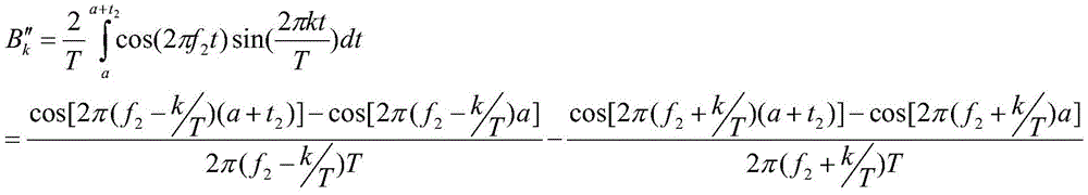

as shown in the formula (5), when k is 1200, the formula That is, the frequency component of k 1200 is equal to the center frequency of the
 pulse signal 2; when k is 1500, then That is, the frequency component of k 1500 is equal to the center frequency of the
 pulse signal 1; the pulse signal 1 and the pulse signal 2 have an overlapping part, so that the pulse signal 1 and the pulse signal 2 inevitably have a problem of frequency domain overlapping, i.e. frequency domain interference, and the frequency component of the overlapping part needs to be eliminated;
reconstructing the fourier series expansion of the pulse signal 2 is equivalent to making the fourier series outside k e [1150,1250] equal to 0, that is, the corresponding fourier series of the frequency component outside 57.5MHz to 62.5MHz is 0, and the reconstruction expression of the fourier series expansion of the pulse signal 2 is as follows:

by reconstructing the Fourier series expansion of the pulse signal 2, the pulse signal 2 does not contain the frequency component of the pulse signal 1, so that the frequency domain interference of the pulse signal 1 to the pulse signal 2 is eliminated.
Due to the reference frequency f of the digital-to-analog conversion chip 30s200MHz, and a single pulse period T of the pulse signal is 20us, so that the number of sample points in the single pulse period is 4000, i.e. at time intervals in the single pulse period Reading from the 1 st sample value to the 4000 th sample value;
the signal reconstruction unit 10 extracts 4000 sample values as a digital signal 1 in a single pulse period for the pulse signal 1 after signal reconstruction, and the expression is as follows:

the signal reconstruction unit 10 further extracts 4000 sample values as the digital signal 2 in a single pulse period for the pulse signal 2 after signal reconstruction, and the expression is as follows:

by analogy, when the next pulse repetition period comes, the 1 st sample value is read to the 4000 th sample value in turn.
The signal reconstruction unit 10 converts 4000 sample values of the pulse signal 1 after signal reconstruction in a single pulse period into 16-bit complementary codes, that is, 16-bit data of the pulse signal 1; the signal reconstruction unit 10 converts 4000 sample values of the reconstructed pulse signal 2 in a single pulse period into a 16-bit complement code, that is, 16-bit data of the pulse signal 2.
The FPGA chip 20 comprises R0M1, a ROM2, a splicing module and a sending module; both the ROM1 and the ROM2 are memories of the FPGA chip 20; in this embodiment, the model of the FPGA chip 20 is EP4SGX230KF 4013;
the signal reconstruction unit 10 stores the 16-bit data of the pulse signal 1 in the ROM1 of the FPGA chip 20 in the form of an MIF file, and the signal reconstruction unit 10 stores the 16-bit data of the pulse signal 2 in the ROM2 of the FPGA chip 20 in the form of an MIF file. The MIF file is a memory initialization file; both the ROM1 and the ROM2 read data at the clock DCLK _ out; the clock DCLK _ out is a clock signal of the digital-to-analog conversion chip 30, and the frequency of the clock DCLK _ out is the same as the reference frequency of the digital-to-analog conversion chip 30.
The splicing module performs data splicing on the 16-bit data of the pulse signal 1 and the 16-bit data of the pulse signal 2 under the clock DCLK _ out to obtain a 32-bit signal; and the upper 16 bits of the 32-bit signal are used to store 16-bit data of pulse signal 1 and the lower 16 bits of the 32-bit signal are used to store 16-bit data of pulse signal 2.
The sending module transmits the 32-bit signal to the analog-to-digital conversion chip under the clock DCLK _ out, wherein the high 16 bits of the 32-bit signal, namely the 16-bit data of the pulse signal 1, are transmitted on the rising edge of the clock DCLK _ out, and the low 16 bits of the 32-bit signal, namely the 16-bit data of the pulse signal 2, are transmitted on the falling edge of the clock DCLK _ out.
The digital-to-analog conversion chip 30 is a dual-channel chip, and includes two channels, i.e., a channel 1 and a channel 2; the digital-to-analog conversion chip 30 sends an analog signal 1 to the signal synthesis unit 40 through a channel 1; the digital-to-analog conversion chip 30 also sends the analog signal 2 to the signal synthesis unit 40 via the channel 2. In this embodiment, the model of the digital-to-analog conversion chip 30 is AD 9783.
The signal synthesizing unit 40 is a one-to-two power divider, which includes two output ends and an input end, and since the input and output of the power divider are equivalent to coupling, in the present invention, the one-to-two power divider performs signal synthesis in a direction connection manner; the digital-to-analog conversion chip 30 sends an analog signal 1 to one of two output ends of the one-to-two power divider; the digital-to-analog conversion chip 30 sends the analog signal 2 to the other end of the two output ends of the one-to-two power divider; and the synthesized path of dipulse signal is output through one input end of the one-to-two power divider.
As shown in fig. 3, the frequency spectrum of the pulse signal 2 at the frequency of 60MHz and the frequency spectrum of the pulse signal 1 at the frequency of 75MHz have a severe frequency domain overlap between the pulse signal 1 and the pulse signal 2, and the side lobes of the two pulse signals overlap.
As shown in fig. 4, after the signal reconstruction of the present invention, the frequency domain overlap between the impulse signal 1 and the impulse signal 2 is improved a lot, and the side lobes of the two impulse signals do not overlap.
As shown in fig. 5, in the prior art, after the dipulse signal is transmitted through the radar antenna, if the dipulse signal encounters a target such as an aircraft, the dipulse signal is inevitably reflected back to the radar antenna and received by the radar antenna, and the received dipulse echo signal is immediately demodulated by the radar.
As shown in fig. 6, since there is frequency domain interference between the conventional dipulse signals, it may affect the demodulation of the multipulse echo signal, taking pulse signal 1 obtained by demodulating the conventional dipulse signal as an example, since pulse signal 2 leaves large pulse time domain interference in the baseband demodulated signal of pulse signal 1, this interference greatly affects the detection function of pulse signal 1.
As shown in fig. 7, since there is no frequency domain interference between the dipulse signals synthesized by the dipulse signal synthesizer of the present invention, it will not affect the demodulation of the dipulse echo signal, and taking pulse signal 1 obtained by demodulating the dipulse signal of the present invention as an example, since the frequency domain interference of pulse signal 2 to pulse signal 1 is eliminated, pulse signal 2 will not leave pulse time domain interference in the baseband demodulated signal of pulse signal 1.
Meanwhile, based on the signal reconstruction mode, the double-pulse signal synthesizer can be expanded into a multi-pulse signal synthesizer.
The invention is not to be considered as limited to the specific embodiments shown and described, but is to be understood to cover all modifications, equivalents, and alternatives falling within the spirit and scope of the invention as defined by the appended claims.
Claims (10)
1. A dual pulse signal synthesizer for improving inter-pulse interference, comprising: the device comprises a signal reconstruction unit, an FPGA chip, a digital-to-analog conversion chip and a signal synthesis unit;
the signal reconstruction unit respectively performs signal reconstruction on the pulse signal 1 and the pulse signal 2 to respectively obtain a pulse signal 1 after the signal reconstruction and a pulse signal 2 after the signal reconstruction; the signal reconstruction is to reconstruct a Fourier series expansion of the pulse signal, only the Fourier series corresponding to the frequency component within 2.5MHz away from the left and right of the central frequency of the pulse signal is reserved, and the Fourier series corresponding to the frequency component beyond 2.5MHz away from the left and right of the central frequency of the pulse signal is equal to 0;
the signal reconstruction unit also respectively extracts samples in a single pulse period from the pulse signal 1 after signal reconstruction and the pulse signal 2 after signal reconstruction to obtain a sample value, namely a digital signal 1, of the pulse signal 1 after signal reconstruction in the single pulse period and a sample value, namely a digital signal 2, of the pulse signal 2 after signal reconstruction in the single pulse period;
the signal reconstruction unit respectively stores a digital signal 1 and a digital signal 2 into the FPGA chip;
the digital-to-analog conversion chip respectively acquires a digital signal 1 and a digital signal 2 from the FPGA chip, and respectively performs digital-to-analog conversion on the two digital signals to obtain an analog signal 1 of the pulse signal 1 after signal reconstruction in a single pulse period and an analog signal 2 of the pulse signal 2 after signal reconstruction in a single pulse period;
the digital-to-analog conversion chip respectively sends an analog signal 1 and an analog signal 2 to the signal synthesis unit;
and the signal synthesis unit is used for carrying out signal synthesis on the analog signal 1 and the analog signal 2 to synthesize a path of dipulse signal.
2. The dipulse signal synthesizer of claim 1, wherein said signal reconstruction unit is configured to perform signal reconstruction on the pulse signal 1 and the pulse signal 2 respectively by using Matlab simulation software.
3. A double pulse signal synthesizer as claimed in claim 2 wherein the pulse signal 1 has a time width t1Center frequency of f1(ii) a The single pulse period of the pulse signal 1 is T;
in the Fourier series expansion of the pulse signal 1, when I.e. k is T f1The frequency component of the time is equal to the center frequency f of the pulse signal 11(ii) a k represents the corresponding series of Fourier series expansion;
the signal reconstruction unit reconstructs the fourier series expansion of the pulse signal 1, which corresponds to k ∈ [ (T × f)1-T*2.5),(T*f1+T*2.5)]The outer Fourier series is equal to 0, and the frequency component is at f1-2.5MHz to f1The corresponding Fourier series outside +2.5MHz is 0.
4. A double pulse signal synthesizer as claimed in claim 2 wherein the pulse signal 2 has a time width t2Center frequency of f2(ii) a The single pulse period of the pulse signal 2 is also T;
in the Fourier series expansion of the pulse signal 2, when When k is T f2The frequency component of the time is equal to the center frequency f of the pulse signal 22(ii) a k represents the corresponding series of Fourier series expansion;
the signal reconstruction unit reconstructs the fourier series expansion of the pulse signal 2, which corresponds to k ∈ [ (T × f)2-T*2.5),(T*f2+T*2.5)]The outer Fourier series is equal to 0, i.e. the frequency component is at f2-2.5MHz to f2The corresponding Fourier series outside +2.5MHz is 0.
5. A double-pulse signal synthesizer as claimed in any one of claims 3 or 4 in which the reference frequency of the DAC chip is fs(ii) a Since the single pulse period of the pulse signal is T, the number of sample points in the single pulse period is fsT are provided;
the signal reconstruction unit extracts f from the pulse signal 1 after signal reconstruction in a single pulse periods*TThe individual sample values are taken as digital signals 1;
the signal reconstruction unit extracts f from the reconstructed pulse signal 2 in a single pulse periodsT sample values are used as the digital signal 2.
6. The double-pulse signal synthesizer according to claim 1, wherein the signal reconstruction unit converts the sample value of the pulse signal 1 after signal reconstruction in a single pulse period into 16-bit complement, i.e. 16-bit data of the pulse signal 1; the signal reconstruction unit converts a sample value of the pulse signal 2 after signal reconstruction in a single pulse period into a 16-bit complement code, namely 16-bit data of the pulse signal 2;
the signal reconstruction unit saves 16-bit data of the pulse signal 1 in the ROM1 of the FPGA chip in the form of an MIF file, and the signal reconstruction unit saves 16-bit data of the pulse signal 2 in the ROM2 of the FPGA chip in the form of an MIF file;
the MIF file is a memory initialization file; the ROM1 and the ROM2 are both memories of the FPGA chip; both the ROM1 and the ROM2 read data at the clock DCLK _ out; the clock DCLK _ out is a clock signal of the digital-to-analog conversion chip, and the frequency of the clock DCLK _ out is the same as the reference frequency of the digital-to-analog conversion chip.
7. The double-pulse signal synthesizer for improving the inter-pulse interference according to claim 6, wherein the FPGA chip further comprises a splicing module and a sending module;
the splicing module performs data splicing on the 16-bit data of the pulse signal 1 and the 16-bit data of the pulse signal 2 under the clock DCLK _ out to obtain a 32-bit signal; and the upper 16 bits of the 32-bit signal are used for storing 16-bit data of the pulse signal 1, and the lower 16 bits of the 32-bit signal are used for storing 16-bit data of the pulse signal 2;
the sending module transmits the 32-bit signal to the analog-to-digital conversion chip under the clock DCLK _ out, wherein the high 16 bits of the 32-bit signal, namely the 16-bit data of the pulse signal 1, are transmitted on the rising edge of the clock DCLK _ out, and the low 16 bits of the 32-bit signal, namely the 16-bit data of the pulse signal 2, are transmitted on the falling edge of the clock DCLK _ out.
8. The double-pulse signal synthesizer for improving inter-pulse interference according to claim 1, wherein the digital-to-analog conversion chip comprises two channels, channel 1 and channel 2; the digital-to-analog conversion chip sends an analog signal 1 to the signal synthesis unit through a channel 1; the digital-to-analog conversion chip also sends the analog signal 2 to the signal synthesis unit through the channel 2.
9. The dipulse signal synthesizer of claim 1, wherein the signal synthesis unit is a one-to-two power divider comprising two output terminals and an input terminal, and the one-to-two power divider is connected in a direction; the digital-to-analog conversion chip sends an analog signal 1 to one of two output ends of the one-to-two power divider; the digital-to-analog conversion chip sends an analog signal 2 to the other end of the two output ends of the one-to-two power divider; and the synthesized path of dipulse signal is output through one input end of the one-to-two power divider.
10. A dipulse signal synthesizer for improving inter-pulse interference according to claim 1, further comprising a signal source; the signal source is used for setting the reference frequency of the FPGA chip and the reference frequency of the digital-to-analog conversion chip.
Priority Applications (1)
| Application Number | Priority Date | Filing Date | Title |
|---|---|---|---|
| CN201811402837.3A CN109557509B (en) | 2018-11-23 | 2018-11-23 | Double-pulse signal synthesizer for improving inter-pulse interference |
Applications Claiming Priority (1)
| Application Number | Priority Date | Filing Date | Title |
|---|---|---|---|
| CN201811402837.3A CN109557509B (en) | 2018-11-23 | 2018-11-23 | Double-pulse signal synthesizer for improving inter-pulse interference |
Publications (2)
| Publication Number | Publication Date |
|---|---|
| CN109557509A CN109557509A (en) | 2019-04-02 |
| CN109557509B true CN109557509B (en) | 2020-08-11 |
Family
ID=65867069
Family Applications (1)
| Application Number | Title | Priority Date | Filing Date |
|---|---|---|---|
| CN201811402837.3A Active CN109557509B (en) | 2018-11-23 | 2018-11-23 | Double-pulse signal synthesizer for improving inter-pulse interference |
Country Status (1)
| Country | Link |
|---|---|
| CN (1) | CN109557509B (en) |
Families Citing this family (1)
| Publication number | Priority date | Publication date | Assignee | Title |
|---|---|---|---|---|
| CN113376585B (en) * | 2021-05-21 | 2022-03-15 | 电子科技大学 | A high-resolution pulse signal synthesis device |
Citations (12)
| Publication number | Priority date | Publication date | Assignee | Title |
|---|---|---|---|---|
| CN103986685A (en) * | 2014-06-03 | 2014-08-13 | 中国人民解放军信息工程大学 | Signal processing method and device |
| CN104125801A (en) * | 2011-10-03 | 2014-10-29 | 海浪科技有限公司 | Nonlinear imaging with dual band pulse complexes |
| CN104981867A (en) * | 2013-02-14 | 2015-10-14 | 杜比实验室特许公司 | Methods for controlling inter-channel coherence of upmixed audio signals |
| CN104995676A (en) * | 2013-02-14 | 2015-10-21 | 杜比实验室特许公司 | Signal decorrelation in an audio processing system |
| CN105324815A (en) * | 2013-05-31 | 2016-02-10 | 歌拉利旺株式会社 | Signal processing device and signal processing method |
| CN106204466A (en) * | 2016-06-24 | 2016-12-07 | 南京理工大学 | A kind of self-adaptive solution method for Fourier lamination micro-imaging technique |
| CN106663448A (en) * | 2014-07-04 | 2017-05-10 | 歌拉利旺株式会社 | Signal processing device and signal processing method |
| CN106772370A (en) * | 2016-12-19 | 2017-05-31 | 上海理工大学 | The sparse imaging method in Terahertz near field based on MIMO array |
| CN107195289A (en) * | 2016-05-28 | 2017-09-22 | 浙江大学 | A kind of editable multistage Timbre Synthesis system and method |
| CN107847141A (en) * | 2015-07-09 | 2018-03-27 | 佳能株式会社 | For obtaining equipment, the methods and procedures of the information relevant with the position displacement of multiple images data set |
| CN108169553A (en) * | 2018-01-10 | 2018-06-15 | 长沙理工大学 | Electric energy gauging method under the conditions of distorted signal based on wavelet transformation and curve matching |
| CN109348739A (en) * | 2016-02-25 | 2019-02-15 | 凝聚技术公司 | Reference Signal Packaging for Wireless Communication |
Family Cites Families (2)
| Publication number | Priority date | Publication date | Assignee | Title |
|---|---|---|---|---|
| CN103886615B (en) * | 2013-12-31 | 2016-04-20 | 华中科技大学 | The separating estimation method of parameter of doing more physical exercises in a kind of X ray angiographic image |
| JP6753698B2 (en) * | 2016-05-27 | 2020-09-09 | クラリオン株式会社 | Propagation delay time calculation device, playback device, propagation delay time calculation system and propagation delay time calculation program |
-
2018
- 2018-11-23 CN CN201811402837.3A patent/CN109557509B/en active Active
Patent Citations (12)
| Publication number | Priority date | Publication date | Assignee | Title |
|---|---|---|---|---|
| CN104125801A (en) * | 2011-10-03 | 2014-10-29 | 海浪科技有限公司 | Nonlinear imaging with dual band pulse complexes |
| CN104981867A (en) * | 2013-02-14 | 2015-10-14 | 杜比实验室特许公司 | Methods for controlling inter-channel coherence of upmixed audio signals |
| CN104995676A (en) * | 2013-02-14 | 2015-10-21 | 杜比实验室特许公司 | Signal decorrelation in an audio processing system |
| CN105324815A (en) * | 2013-05-31 | 2016-02-10 | 歌拉利旺株式会社 | Signal processing device and signal processing method |
| CN103986685A (en) * | 2014-06-03 | 2014-08-13 | 中国人民解放军信息工程大学 | Signal processing method and device |
| CN106663448A (en) * | 2014-07-04 | 2017-05-10 | 歌拉利旺株式会社 | Signal processing device and signal processing method |
| CN107847141A (en) * | 2015-07-09 | 2018-03-27 | 佳能株式会社 | For obtaining equipment, the methods and procedures of the information relevant with the position displacement of multiple images data set |
| CN109348739A (en) * | 2016-02-25 | 2019-02-15 | 凝聚技术公司 | Reference Signal Packaging for Wireless Communication |
| CN107195289A (en) * | 2016-05-28 | 2017-09-22 | 浙江大学 | A kind of editable multistage Timbre Synthesis system and method |
| CN106204466A (en) * | 2016-06-24 | 2016-12-07 | 南京理工大学 | A kind of self-adaptive solution method for Fourier lamination micro-imaging technique |
| CN106772370A (en) * | 2016-12-19 | 2017-05-31 | 上海理工大学 | The sparse imaging method in Terahertz near field based on MIMO array |
| CN108169553A (en) * | 2018-01-10 | 2018-06-15 | 长沙理工大学 | Electric energy gauging method under the conditions of distorted signal based on wavelet transformation and curve matching |
Also Published As
| Publication number | Publication date |
|---|---|
| CN109557509A (en) | 2019-04-02 |
Similar Documents
| Publication | Publication Date | Title |
|---|---|---|
| CN106483512B (en) | A kind of general multichannel distributed object analogue echoes method and if system | |
| CN102707263B (en) | Multi-frequency multi-base high-frequency ground wave radar system and operating method thereof | |
| CN108427102B (en) | Radar baseband clutter generation device and method | |
| CN102590794A (en) | Broadband coherent radar target simulator | |
| Hakobyan | Orthogonal frequency division multiplexing multiple-input multiple-output automotive radar with novel signal processing algorithms | |
| CN103364765A (en) | Digital radio frequency memory based on analogue demodulation/modulation | |
| CN103529433A (en) | Linear frequency modulation radar target speed simulation method and echo signal simulation source | |
| CN107066693B (en) | Multi-channel and multi-target spaceborne AIS reconnaissance signal simulation system | |
| CN102680966A (en) | Navigation radar for FMCW (frequency-modulated continuous wave) ship | |
| CN106405585A (en) | Radiofrequency signal acquisition playback method and radiofrequency signal acquisition playback device | |
| CN106772264A (en) | A kind of ground and spaceborne general ultra-wideband radar signal generating means and method | |
| CN103777182A (en) | Multi-channel multi-basis synthetic aperture radar fixed receiver and data processing method thereof | |
| CN100386645C (en) | Method and Radar System for Detecting Surface Velocity of Rivers and Lakes by Radar Waves | |
| CN107367717A (en) | A kind of Radar Multi Target intermediate frequency simulator | |
| CN109557509B (en) | Double-pulse signal synthesizer for improving inter-pulse interference | |
| CN107102328B (en) | FPGA-based real-time imaging signal processing method and FPGA | |
| CN203133273U (en) | High-frequency surface wave radar data collecting and processing apparatus based on CPCI bus | |
| CA2191813C (en) | Radio navigation testing method and device using standard signal measuring and generating equipment | |
| CN111751799A (en) | An ultra-wideband multi-target detection method | |
| US20230096861A1 (en) | Integrated radar signal processing circuit | |
| CN108107409A (en) | A kind of intermediate-freuqncy signal source and its signal generating method of MIMO radar target seeker | |
| CN205120960U (en) | Dualbeam point mark data processing device based on DSP and FPGA | |
| CN111030765A (en) | A Heterodyne Scanning Spectrum Analysis System That Can Identify Image Frequency Signals | |
| US4644357A (en) | Radar clutter simulator | |
| KR20180058896A (en) | Apparatus for SDR-MRSP processor |
Legal Events
| Date | Code | Title | Description |
|---|---|---|---|
| PB01 | Publication | ||
| PB01 | Publication | ||
| SE01 | Entry into force of request for substantive examination | ||
| SE01 | Entry into force of request for substantive examination | ||
| GR01 | Patent grant | ||
| GR01 | Patent grant |