CN109349681B - Porous heating element, atomizer containing porous heating element and porous body preparation method - Google Patents
Porous heating element, atomizer containing porous heating element and porous body preparation method Download PDFInfo
- Publication number
- CN109349681B CN109349681B CN201811357202.6A CN201811357202A CN109349681B CN 109349681 B CN109349681 B CN 109349681B CN 201811357202 A CN201811357202 A CN 201811357202A CN 109349681 B CN109349681 B CN 109349681B
- Authority
- CN
- China
- Prior art keywords
- porous
- porous body
- heating
- hole
- raw material
- Prior art date
- Legal status (The legal status is an assumption and is not a legal conclusion. Google has not performed a legal analysis and makes no representation as to the accuracy of the status listed.)
- Active
Links
Images


Classifications
-
- A24F47/008—
Landscapes
- Resistance Heating (AREA)
- Catching Or Destruction (AREA)
Abstract
本发明提出一种多孔体制备方法,方法包括按照各质量百分数的如下成分获取原料:硅藻土50%~75%、氧化铝0%~10%、造孔剂15%~35%、粘土5%~10%、玻璃粉5%~15%;将原料与石蜡均匀混合后制成原料蜡块;将原料蜡块按照所需形状压制成型,获得生胚;将生胚先于200~500℃下保温4~10h、再于700~1200℃下烧结2~4h,得到多孔体。本发明制备的多孔体,相比通常的普通陶瓷棒,体现在电子烟上出烟容易快,烟雾量相对大。

The invention provides a method for preparing a porous body. The method includes obtaining raw materials according to the following components in various mass percentages: diatomite 50%-75%, alumina 0%-10%, pore-forming agent 15%-35%, clay 5% %~10%, glass powder 5%~15%; mix the raw material and paraffin uniformly to make raw material wax block; press and shape the raw material wax block according to the desired shape to obtain the raw embryo; The temperature is kept for 4-10 hours, and then sintered at 700-1200 DEG C for 2-4 hours to obtain a porous body. Compared with ordinary ceramic rods, the porous body prepared by the present invention is reflected in that the electronic cigarette is easy and fast to emit smoke, and the amount of smoke is relatively large.
Description
技术领域technical field
本发明实施例涉及电子烟技术领域,尤其涉及一种多孔发热体、包含多孔发热体的雾化器及多孔体制备方法。Embodiments of the present invention relate to the technical field of electronic cigarettes, and in particular, to a porous heating body, an atomizer including the porous heating body, and a method for preparing the porous body.
背景技术Background technique
电子烟产品的核心部件为对电子烟油进行蒸发胶的雾化器,雾化器的功能实现主要是基于一多孔体、以及一发热元件组成。其中,多孔体是一个自身内部具有毛细微孔的部件,可以通过内部的微孔进行烟油的浸润吸收和传导;而发热元件具有用于发热的发热部分、以及导电引脚部分,发热部分用于对多孔体传导来的烟油进行加热蒸发,形成供吸食的烟油气溶胶。The core component of the electronic cigarette product is the atomizer that evaporates the electronic cigarette oil. The function of the atomizer is mainly based on a porous body and a heating element. Among them, the porous body is a component with capillary pores inside, which can infiltrate, absorb and conduct e-liquid through the internal pores; and the heating element has a heating part for heating and a conductive pin part, and the heating part uses It heats and evaporates the smoke oil conducted by the porous body to form smoke oil aerosol for smoking.
目前,多孔体的通常有多孔纤维、多孔陶瓷、发泡金属等等;这些刚性结构的多孔体,在使用中通常采用空心柱状/或者是方块状设计,发热件嵌在陶瓷体内部,然后整体安装在固定尺寸的雾化器外壳套内。At present, porous bodies usually include porous fibers, porous ceramics, foamed metals, etc.; these porous bodies with rigid structures are usually designed in the form of hollow cylinders/or blocks in use, and the heating element is embedded in the ceramic body, and then Integrally mounted in a fixed size nebulizer housing.
以上形状和结构的多孔体,一方面在多孔体内外径恒定前提下,空心柱状结构浸润导油速度相对慢,容易导油不足,引起香精香料分解,导致口感体验中还原度不够,或者发热丝干烧产生糊味;而且外径恒定的柱形,不便于设置与雾化器外壳套固定和连接的结构部件,不便于实现稳定的装配和密封。The porous body of the above shape and structure, on the one hand, under the premise that the outer diameter of the porous body is constant, the hollow columnar structure infiltration and oil conduction speed is relatively slow, and it is easy to insufficient oil conduction, causing the decomposition of flavors and fragrances, resulting in insufficient reduction in taste experience, or heating wire Dry burning produces a mushy smell; and the cylindrical shape with a constant outer diameter is inconvenient to set up structural components that are fixed and connected to the atomizer casing, and is inconvenient to achieve stable assembly and sealing.
发明内容SUMMARY OF THE INVENTION
为了解决现有技术中的多孔导油体导油和装配的问题,本发明实施例提供一种导油性更好、且便于装配和密封的多孔发热体。In order to solve the problem of oil guiding and assembly of the porous oil-conducting body in the prior art, the embodiment of the present invention provides a porous heating body with better oil-conducting performance and convenient assembly and sealing.
本发明实施例提供的多孔发热体,多孔发热体,包括用于传导液体的多孔体,所述多孔体包括沿该多孔体的长度方向依次设置的第一多孔部、第二多孔部和第三多孔部;且沿所述多孔体的宽度方向上,所述第一多孔部和第三多孔部的截面面积均大于第二多孔部;The porous heating body provided by the embodiment of the present invention includes a porous body for conducting liquid, and the porous body includes a first porous part, a second porous part and a a third porous portion; and along the width direction of the porous body, the cross-sectional areas of the first porous portion and the third porous portion are both larger than the second porous portion;
所述多孔体上设有沿多孔体长度方向延伸的发热元件,该发热元件具有用于雾化液体以生成气溶胶的发热部;所述发热部沿多孔体长度方向上的延伸长度的至少一部分与所述第二多孔部的延伸长度相重叠。The porous body is provided with a heating element extending along the length direction of the porous body, and the heating element has a heating part for atomizing liquid to generate aerosol; at least a part of the extension length of the heating part along the length direction of the porous body It overlaps with the extended length of the second porous portion.
优选地,所述第一多孔部沿多孔体宽度方向上的截面面积恒定;Preferably, the cross-sectional area of the first porous portion along the width direction of the porous body is constant;
和/或,and / or,
所述第二多孔部沿多孔体宽度方向上的截面面积恒定;The cross-sectional area of the second porous portion along the width direction of the porous body is constant;
和/或,and / or,
所述第三多孔部沿多孔体宽度方向上的截面面积恒定。The cross-sectional area of the third porous portion in the width direction of the porous body is constant.
优选地,沿所述多孔体的长度方向、且朝第二多孔部的方向上,所述第一多孔部沿多孔体宽度方向上的截面面积逐渐减小。Preferably, the cross-sectional area of the first porous portion in the width direction of the porous body gradually decreases along the length direction of the porous body and in the direction toward the second porous portion.
优选地,沿所述多孔体的长度方向、且朝第二多孔部的方向上,所述第一多孔部包括依次设置的第一导油段和第二导油段;其中,Preferably, along the length direction of the porous body and in the direction toward the second porous portion, the first porous portion includes a first oil guide section and a second oil guide section arranged in sequence; wherein,
所述第一导油段沿宽度方向上的截面面积恒定;The cross-sectional area of the first oil guide section along the width direction is constant;
沿所述多孔体的长度方向、且朝第二多孔部的方向上,所述第二导油段沿宽度方向上的截面面积逐渐减小。Along the length direction of the porous body and toward the second porous portion, the cross-sectional area of the second oil guide section along the width direction gradually decreases.
优选地,沿所述多孔体的长度方向、且朝第二多孔部的方向上,所述第三多孔部沿多孔体宽度方向上的截面面积逐渐减小。Preferably, the cross-sectional area of the third porous portion in the width direction of the porous body gradually decreases along the length direction of the porous body and in the direction toward the second porous portion.
优选地,沿所述多孔体的长度方向、且朝第二多孔部的方向上,所述第三多孔部包括依次设置的第三导油段和第四导油段;其中,Preferably, along the length direction of the porous body and in the direction toward the second porous portion, the third porous portion includes a third oil guide section and a fourth oil guide section arranged in sequence; wherein,
所述第三导油段沿宽度方向上的截面面积恒定;The cross-sectional area of the third oil guide section along the width direction is constant;
沿所述多孔体的长度方向、且朝第二多孔部的方向上,所述第四导油段沿宽度方向上的截面面积逐渐减小。Along the length direction of the porous body and the direction toward the second porous portion, the cross-sectional area of the fourth oil guide section along the width direction gradually decreases.
在以上多孔发热体的基础上,本发明进一步还提出包含上述多孔发热体的雾化器产品;具体雾化器,包括中空外壳体,该外壳体内具有用于存储烟油的储油腔;所述外壳体内还设置有用于从储油腔吸取烟油、并对烟油进行雾化的多孔发热体;所述多孔发热体为以上所述的多孔发热体。On the basis of the above porous heating body, the present invention further proposes an atomizer product including the above porous heating body; a specific atomizer includes a hollow outer casing, and the outer casing has an oil storage cavity for storing e-liquid; so The outer casing is also provided with a porous heating body for absorbing e-liquid from the oil storage cavity and atomizing the e-liquid; the porous heating body is the above-mentioned porous heating body.
优选地,所述多孔体上还设置有至少一个沿该多孔体的长度方向依次贯穿所述第一多孔部、第二多孔部和第三多孔部的通孔。Preferably, the porous body is further provided with at least one through hole penetrating the first porous part, the second porous part and the third porous part in sequence along the length direction of the porous body.
优选地,所述多孔体上还设置有至少一个沿该多孔体的长度方向依次贯穿所述第一多孔部、第二多孔部和第三多孔部的通孔。Preferably, the porous body is further provided with at least one through hole penetrating the first porous part, the second porous part and the third porous part in sequence along the length direction of the porous body.
优选地,所述通孔内壁包括第一烟油工作面;且沿所述通孔的径向方向,所述第二多孔部具有与第一烟油工作面相对应的第二烟油工作面;Preferably, the inner wall of the through hole includes a first e-liquid working surface; and along the radial direction of the through hole, the second porous portion has a second e-liquid working surface corresponding to the first e-liquid working surface ;
且当所述通孔的数量为两个以上时,沿所述通孔的径向方向,所述第一烟油工作面与第二烟油工作面的间距相同。And when the number of the through holes is more than two, along the radial direction of the through holes, the distance between the first e-liquid working surface and the second e-liquid working surface is the same.
优选地,所述通孔用于导出气溶胶;所述第一烟油工作面被配置为雾化烟油的雾化面,所述发热元件的发热部设于该雾化面上;所述第二烟油工作面被配置为与烟油接触的液体接触面。Preferably, the through hole is used for exporting aerosol; the first e-liquid working surface is configured as an atomizing surface for atomizing e-liquid, and the heating part of the heating element is arranged on the atomizing surface; the The second e-liquid working surface is configured as a liquid contact surface in contact with the e-liquid.
优选地,所述通孔内壁具有两个相对的雾化面,两个雾化面上对应设置有第一发热部和第二发热部,所述第一发热部和第二发热部以并联或串联的方式连接。Preferably, the inner wall of the through hole has two opposite atomizing surfaces, and the two atomizing surfaces are provided with a first heating part and a second heating part correspondingly, and the first heating part and the second heating part are connected in parallel or in parallel. connected in series.
优选地,所述通孔与所述储油腔相连通,所述第一烟油工作面被配置为与烟油接触的液体接触面,所述第二烟油工作面被配置为雾化烟油的雾化面,所述发热部设于该雾化面上。Preferably, the through hole is communicated with the oil storage cavity, the first e-liquid working surface is configured as a liquid contact surface in contact with e-liquid, and the second e-liquid working surface is configured as atomized smoke The atomization surface of the oil, and the heat generating part is provided on the atomization surface.
优选地,所述烟油经液体接触面传导至对应雾化面的最短传导距离,小于所述通孔内壁沿该通孔的径向方向与第一多孔部或第三多孔部外表之间的距离。Preferably, the shortest conduction distance of the e-liquid from the liquid contact surface to the corresponding atomizing surface is smaller than the distance between the inner wall of the through hole and the outer surface of the first porous part or the third porous part along the radial direction of the through hole. distance between.
优选地,所述通孔包括沿该多孔体的长度方向依次贯穿所述第一多孔部、第二多孔部和第三多孔部的第一通孔和第二通孔;Preferably, the through hole includes a first through hole and a second through hole that pass through the first porous part, the second porous part and the third porous part in sequence along the length direction of the porous body;
所述发热元件包括设于所述第一通孔的雾化面的第一发热部、以及设于所述第二通孔的雾化面的第二发热部;且所述第一发热部与第二发热部被配置为具有不同的发热温度。The heating element includes a first heating part arranged on the atomizing surface of the first through hole, and a second heating part arranged on the atomizing surface of the second through hole; and the first heating part and the The second heat-generating parts are configured to have different heat-generating temperatures.
优选地,所述外壳体内设有用于将多孔发热体雾化生成的烟油气溶胶输出至雾化器外的烟气传输管、用于固定所述多孔发热体的固定座、以及用于连接所述多孔发热体和烟气传输管的连接件;其中,Preferably, the outer casing is provided with a flue gas transmission pipe for outputting the smoke gas aerosol generated by the atomization of the porous heating body to the outside of the atomizer, a fixing seat for fixing the porous heating body, and a connection for connecting the The connecting piece of the porous heating body and the flue gas transmission pipe; wherein,
所述固定座上设有与第一多孔部适配的第一容纳部;a first accommodating part adapted to the first porous part is arranged on the fixing seat;
所述连接件具有与第三多孔部适配的第二容纳部、以及与所述烟气传输管连接的连接部;the connecting piece has a second accommodating part adapted to the third porous part, and a connecting part connected with the flue gas transmission pipe;
所述多孔发热体通过第一多孔部和第一容纳部的配合与固定座连接、及通过第三多孔部和第二容纳部的配合与连接件连接。The porous heating body is connected to the fixing base through the cooperation of the first porous part and the first accommodating part, and is connected to the connecting piece through the cooperation of the third porous part and the second accommodating part.
采用本发明的以上多孔发热体,通过将多孔体采用中间细小、两端粗大的哑铃状形状,中间部分相对具有更短的烟油传导距离,烟油传导的更加快捷,有利于提升烟油雾化时的导油性。两端突出部位一方面能起到储油的效果补充中间部分的烟油消耗,从而雾化时提升烟油补充效率;另一方面便于与其他部件进行固定和密封衔接;同时还能减少热量向两端与多孔发热体连接的部件传导。Using the above porous heating element of the present invention, by adopting the porous body in the shape of a dumbbell with a small middle and thick ends, the middle part has a relatively shorter e-liquid conduction distance, and the e-liquid conducts more quickly, which is beneficial to improve e-liquid mist. Oil conductivity during melting. On the one hand, the protruding parts at both ends can store oil and supplement the consumption of e-liquid in the middle part, thereby improving the efficiency of e-liquid replenishment during atomization; on the other hand, it is convenient for fixing and sealing connection with other components; The parts connected to the porous heating element at both ends conduct conduction.
基于多孔体更高导油效率的立意,本发明还提出一种高出烟量和出烟效率的多孔体制备方法及按照该方法制备获得的多孔体产品,方法包括如下步骤:Based on the idea of higher oil-conducting efficiency of the porous body, the present invention also proposes a method for preparing a porous body with high smoke output and smoke output efficiency, and a porous body product prepared according to the method. The method includes the following steps:
按照各质量百分数的如下成分获取原料:硅藻土50%~75%、氧化铝0%~10%、造孔剂15%~35%、粘土5%~10%、玻璃粉5%~15%;Obtain raw materials according to the following components in each mass percentage:
将所述原料与石蜡混合均匀后制成原料蜡块;The raw material is mixed with the paraffin to make the raw material wax block;
将所述原料蜡块按照所需形状压制成型,获得生胚;Pressing the raw wax block according to the desired shape to obtain a raw embryo;
将所述生胚先于200~500℃下保温4~10h、再于700~1200℃下烧结2~4h,得到多孔体。The green embryo is first kept at 200-500° C. for 4-10 hours, and then sintered at 700-1200° C. for 2-4 hours to obtain a porous body.
优选地,所述造孔剂选自蔗糖、淀粉、木纤维及短碳纤维中的至少一种。Preferably, the pore-forming agent is selected from at least one of sucrose, starch, wood fiber and short carbon fiber.
优选地,将所述原料与石蜡混合均匀后制成原料蜡块步骤之前,还包括:Preferably, before the step of making the raw material wax block after mixing the raw material and the paraffin uniformly, it also includes:
将所述原料于去离子水或无水乙醇介质下进行湿法球磨处理。The raw material is subjected to wet ball milling treatment in deionized water or absolute ethanol medium.
优选地,将所述原料蜡块按照所需形状压制成型步骤中,Preferably, in the step of pressing the raw wax block according to the desired shape,
所述压制成型于温度70~85℃、压力0.4~1MPa条件下进行。The press molding is performed under the conditions of a temperature of 70-85° C. and a pressure of 0.4-1 MPa.
附图说明Description of drawings
一个或多个实施例通过与之对应的附图中的图片进行示例性说明,这些示例性说明并不构成对实施例的限定,附图中具有相同参考数字标号的元件表示为类似的元件,除非有特别申明,附图中的图不构成比例限制。One or more embodiments are exemplified by the pictures in the corresponding drawings, and these exemplifications do not constitute limitations of the embodiments, and elements with the same reference numerals in the drawings are denoted as similar elements, Unless otherwise stated, the figures in the accompanying drawings do not constitute a scale limitation.
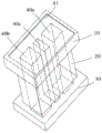
图1是本发明一较佳实施例提供的多孔发热体的立体结构示意图;1 is a schematic three-dimensional structure diagram of a porous heating body provided by a preferred embodiment of the present invention;
图2是另一实施例提供的多孔发热体的长度方向剖面示意图;2 is a schematic cross-sectional view in the longitudinal direction of a porous heating body provided by another embodiment;
图3是又一实施例提供的多孔发热体的立体结构示意图;3 is a schematic three-dimensional structure diagram of a porous heating body provided by another embodiment;
图4是又一实施例提供的多孔发热体的长度方向剖面示意图;4 is a schematic cross-sectional view of a porous heating body in the longitudinal direction provided by another embodiment;
图5是又一实施例提供的多孔发热体的长度方向剖面示意图;5 is a schematic cross-sectional view in the longitudinal direction of a porous heating body provided by another embodiment;
图6是又一实施例提供的多孔发热体的长度方向剖面示意图;6 is a schematic cross-sectional view of a porous heating body in the longitudinal direction provided by another embodiment;
图7是又一实施例提供的多孔发热体的长度方向剖面示意图;7 is a schematic cross-sectional view of a porous heating body in the longitudinal direction provided by another embodiment;
图8是又一实施例提供的多孔发热体的长度方向剖面示意图;8 is a schematic cross-sectional view in the longitudinal direction of a porous heating body provided by another embodiment;
图9是又一实施例提供的多孔发热体的长度方向剖面示意图;9 is a schematic cross-sectional view of a porous heating body in the longitudinal direction provided by another embodiment;
图10是图1实施例的多孔发热体沿长度方向的剖面示意图;10 is a schematic cross-sectional view of the porous heating body of the embodiment of FIG. 1 along the length direction;
图11是又一实施例提供的多孔发热体的长度方向剖面示意图;11 is a schematic cross-sectional view in the longitudinal direction of a porous heating body provided by another embodiment;
图12是又一实施例提供的多孔发热体的长度方向剖面示意图;12 is a schematic cross-sectional view of a porous heating body in the longitudinal direction provided by another embodiment;
图13是又一实施例提供的多孔发热体的长度方向剖面示意图;13 is a schematic cross-sectional view in the longitudinal direction of a porous heating body provided by another embodiment;
图14是图12所示的多孔发热体在雾化器储油腔内的一安装示意图;Fig. 14 is a schematic diagram of the installation of the porous heating element shown in Fig. 12 in the oil storage chamber of the atomizer;
图15是另一较佳实施例提供的多孔发热体的立体结构示意图;15 is a schematic three-dimensional structure diagram of a porous heating body provided by another preferred embodiment;
图16是图15实施例的多孔发热体沿长度方向的剖面示意图;FIG. 16 is a schematic cross-sectional view of the porous heating body of the embodiment of FIG. 15 along the length direction;
图17是又一实施例提供的多孔发热体的结构示意图;17 is a schematic structural diagram of a porous heating body provided by another embodiment;
图18是图17实施例的第二多孔部安装发热部的结构示意图;FIG. 18 is a schematic view of the structure of the second porous part with the heating part installed in the embodiment of FIG. 17;
图19是本发明一实施例提供的雾化器的轴向剖面示意图;19 is a schematic diagram of an axial cross-section of an atomizer provided by an embodiment of the present invention;
图20是图19的雾化器中多孔发热体装配结构的各部件分解示意图;Figure 20 is a schematic exploded view of each component of the porous heating body assembly structure in the atomizer of Figure 19;
图21是图20中硅胶连接件另一视角下的结构示意图;FIG. 21 is a schematic structural diagram of the silicone connector in FIG. 20 from another perspective;
图22是一实施例制备的多孔体与常规陶瓷棒断面扫描电镜分析图。FIG. 22 is a scanning electron microscope analysis diagram of the cross-section of the porous body and the conventional ceramic rod prepared in one example.
具体实施方式Detailed ways
为了便于理解本发明,下面结合附图和具体实施方式,对本发明进行更详细的说明。In order to facilitate understanding of the present invention, the present invention will be described in more detail below with reference to the accompanying drawings and specific embodiments.
本发明实施例的多孔发热体,主要适用于电子烟产品的雾化器,当然基于相同的导油雾化功能,也可以扩展用于液态的药物成分挥发装置或其它芳香成分释放装置中,在本发明的以下实施例中以电子烟为例进行讲述。The porous heating element of the embodiment of the present invention is mainly suitable for the atomizer of electronic cigarette products. Of course, based on the same oil-conducting atomization function, it can also be extended to be used in liquid drug component volatilization devices or other aromatic component release devices. In the following embodiments of the present invention, electronic cigarettes are used as an example for description.
本发明多孔发热体一实施例的外形立体图结构可以参见图1所示,整体的形状大体呈哑铃形形状。具体实施中在图1形状的基础上可以以进行各种类似变化,整体的形状设计结构原理可以参见图2所示进行说明。多孔发热体包括一个纵长延伸的圆筒状的多孔体,以及与该多孔体接触的发热元件,多孔体内部具有微孔结构,用来渗透传导烟油以提供给发热元件,发热元件用来加热烟油生成气溶胶;其中,多孔体包括沿长度方向依次同轴设置的第一多孔部10、第二多孔部20、以及第三多孔部30;并且,Figure 1 shows a three-dimensional view of the structure of an embodiment of the porous heating element of the present invention, and the overall shape is generally in the shape of a dumbbell. In the specific implementation, various similar changes can be made on the basis of the shape of FIG. 1 , and the overall shape design structure principle can be described with reference to FIG. 2 . The porous heating body includes a longitudinally extending cylindrical porous body and a heating element in contact with the porous body. The porous body has a microporous structure inside, which is used to penetrate and conduct the e-liquid to provide the heating element. The heating element is used for heating e-liquid to generate aerosol; wherein, the porous body includes a first
沿宽度方向上,第一多孔部10和第三多孔部30的外径均大于第二多孔部20。In the width direction, the outer diameters of the first
以上结构的多孔体,在沿长度方向上分成三个部分,依次为以上所述的第一多孔部10、第二多孔部20和第三多孔部30,并且宽度方向上使第二多孔部20的外径小于第一多孔部10和第三多孔部30,从而在多孔体的表面上形成一与第二多孔部20相对的凹腔21,使得整体大体为哑铃形形状。发热元件可以通过烧结、印刷、涂覆、蚀刻等方式形成于该多孔体上,也可以是作为一个独立的部件装配于多孔体上。发热元件的结构包括两个部分,分别是用于进行发热的发热部50,以及用于通过将发热部50与电源电极连接,实现为发热部导电的电极引脚(或者称导电连接部,图1至图14实施例的发热元件中未示出电极引脚,图15和图16有示出)。发热部50沿多孔体的长度方向延伸,并且该发热部50设于与第二多孔部20相对应的位置上,即发热部50沿多孔体长度方向的延伸长度的至少一部分与第二多孔部20的延伸长度相重叠,从而提升导油效率和出烟量。发热部50和多孔体的具体结合方式可以是如图7和图8实施例所示,发热部50的卷绕于第二多孔部20的外表面,或者类似图2所示,发热部50附着于第二多孔部20的内表面。The porous body of the above structure is divided into three parts in the longitudinal direction, which are the first
参见图14所示,将多孔发热体安装于雾化器的储油腔C内时,以上多孔发热体助于提升导油性和雾化效率在于,上述第二多孔部20宽度方向上的内外表面分别作为吸油面a和雾化面b,即将第二多孔部20外表面定义成与烟油接触的吸油面a,将通孔内壁表面定义成雾化面b,发热部50位于雾化面b上,吸油面a和雾化面b之间在宽度方向上的烟油最短传输距离d小于第一多孔部10或第三多孔部30外表面与通孔内壁表面之间的烟油传输距离D,因此相比两端的第一多孔部10和第三多孔部30,与发热部50位置相对应的第二多孔部20的烟油的传导效率更高。而两端的第一多孔部10和第三多孔部30形成两端突出的形状,一方面能起到储油的效果补充中间部分的烟油消耗,从而雾化时提升烟油补充效率;另一方面可以便于采用图14所示的分别用两个固定连接部件A和B连接,便于在雾化器内部进行固定和密封衔接;同时第一多孔部10和第三多孔部30的体积比第二多孔部20更大,发热部50产生的热量向多孔体两端的传导可被第一多孔部10和第三多孔部30自身吸收,能减少热量沿长度方向从第二多孔部20向两端传递给上述固定连接部件A和B。Referring to FIG. 14 , when the porous heating body is installed in the oil storage chamber C of the atomizer, the above porous heating body helps to improve the oil conductivity and atomization efficiency in that the inner and outer parts of the second
进一步图中所示的多孔体,发热部50可以采用发热线圈/片状发热网/筒状发热管等,安装时沿着多孔体的长度方向延伸的方式安装在多孔体上,并让发热元件的发热部50在宽度方向上与第二多孔部20相对,即保证使发热部50与第二多孔部20在长度方向的至少一部分与第二多孔部20的延伸长度相重叠,从而具有更好的烟油雾化效率。For the porous body shown in the figure, the
当然,基于通常形状规格的产品构造和功能要求,第二多孔部20为柱状形状,优选为圆柱状/方柱状等;第一多孔部10和第三多孔部30也可与之相对应进行调整。比如图3实施例中,第一多孔部10和第三多孔部30方柱状形状设计,并且内部通孔40对应。通孔40内壁具有两个相对的雾化面,两个雾化面上对应设置有第一发热部50a和第二发热部50b,第一发热部50a和第二发热部50b以并联或串联的方式连接电源组件。Of course, based on the product structure and functional requirements of general shape specifications, the second
进一步,基于多孔发热体使用时需要能适用于内部雾化的需求,因此进一步在除图7外的实施方式中,多孔体均具有沿长度方向依次贯穿第一多孔部10、第二多孔部20和第三多孔部30的通孔40;该通孔40的作用和目的,一方面是能够提供安装螺旋发热圈/筒状发热网/发热丝等发热部50的空间,另一方面该通孔40能作为烟油气溶胶的传输通道,使内部雾化生成的烟油气溶胶传输至雾化器烟气通道。Further, based on the requirement that the porous heating body can be used for internal atomization, further in the embodiments other than FIG. 7 , the porous body has the first
进一步,基于更好的使用和装配效果,在本发明图4至图6实施例的多孔体中,沿长度方向、且朝第二多孔部20的方向上,第一多孔部10沿宽度方向的外径逐渐减小。通过将第一多孔部10设计成外径逐渐减小,朝第二多孔部20过渡的形状设计,过渡的形状更加利于烟油从两端向中间的浸润和传导效率,有利于提升出烟量和出烟效率。在以上第一多孔部10过渡型的设计时,第一多孔部10的表面会呈现朝第二多孔部20倾斜的形状,通常则可以采用多种方式进行,如图4至图6中的凸弧面/凹弧面/平面等方式进行均可。Further, based on better use and assembly effects, in the porous body of the embodiments of FIGS. 4 to 6 of the present invention, along the length direction and in the direction toward the second
同时,为了便于后续能被顺畅与外壳体内的硅胶座等紧密装配,进一步参见图6至图13,第一多孔部10还可以进行分段设计,分段设计的形式如图中所示,包括有两部分,分别为沿着多孔发热体的长度方向、且朝第二多孔部20的方向上,依次设置的第一导油段11和第二导油段12;其中,At the same time, in order to be able to be smoothly and tightly assembled with the silica gel seat in the outer casing in the future, further referring to FIGS. 6 to 13 , the first
第一导油段11为外径恒定的柱状形状,而第二导油段12沿长度方向、且朝第二多孔部20的方向上,外径逐渐减小。那么最终这一分段的形状设计,则可以利用第一导油段11作为两端突出的部分便于与其他部件的装配,而第二导油段12作为过渡形状,促进提升烟油的浸润传导。The first
当然,在以上过渡型的设计时,第二导油段12的表面呈现朝第二多孔部20倾斜的形状,通常则可以采用多种方式进行,如图6至13中的凸弧面/凹弧面/平面,或者组合等方式进行均可。Of course, in the above transitional design, the surface of the second oil-guiding
进一步,本发明以上多孔体可以采用多孔陶瓷、多孔玻璃陶瓷、多孔玻璃、发泡金属等多孔材质,例如由氧化铝、碳化硅或硅藻土等材质做成的蜂窝式陶瓷等硬质毛细结构制成。Further, the above porous body of the present invention can adopt porous materials such as porous ceramics, porous glass ceramics, porous glass, foamed metal, etc., for example, hard capillary structures such as honeycomb ceramics made of materials such as alumina, silicon carbide or diatomite. production.
从以上结构可以看出第三多孔部30是与第一多孔部10相对应的存在,因此以上第三多孔部30的过渡倾斜/分段等结构和形状与第一多孔部10相对应设计,第三多孔部30也可以采用与以上所描述的第一多孔部10的类似进行;在此不再重复赘述。It can be seen from the above structure that the third
同时,以上多孔体与发热元件两者可以采用分别获取之后,再按照各图中所示进行装配结合组成完整的多孔发热体;而在更多的实施场景和使用中,还可以直接将发热元件的原材料采用烧结成型于多孔体的表面上。这种烧结成型的方式具体包括:将发热元件的原材料(比如镍金属粉)与一定量的烧结助剂混合配置成混合浆料;然后采用涂刷的方式按照所需的形状,将混合浆料涂刷在多孔体内/外表面形成印刷层,然后进行烧制即形成在多孔体上的发热元件。或者,发热元件为设于多孔体表面上的发热线路,发热线路包括且不限定于发热材料涂层、电阻浆料印刷线路等形式。将多孔体与发热元件制作为一体结构,可防止发热元件变形或断裂而影响发热性能。At the same time, the above porous body and heating element can be obtained separately, and then assembled and combined as shown in each figure to form a complete porous heating body; and in more implementation scenarios and uses, the heating element can also be directly The raw material is sintered on the surface of the porous body. This sintering molding method specifically includes: mixing the raw materials of the heating element (such as nickel metal powder) with a certain amount of sintering aids to form a mixed slurry; and then brushing the mixed slurry according to the desired shape. The heating element formed on the porous body is formed by painting on the inner/outer surface of the porous body to form a printed layer, and then firing. Alternatively, the heating element is a heating circuit provided on the surface of the porous body, and the heating circuit includes but is not limited to the form of a heating material coating, a resistance paste printed circuit, and the like. The porous body and the heating element are made into an integral structure, which can prevent the heating element from being deformed or broken and affecting the heating performance.
而且,在以上表面设置的方式之外,还可采用如图13所示的内部埋设方式进行发热元件发热部50的安装;通过将发热部50全部埋设于多孔体内,烟油雾化不用传导至发热部50表面接触时才进行,而是在多孔体内靠近发热部50的部位即开始受热雾化;一方面使在发热部50与多孔体存在导热接触不会产生干烧,另一方面大多数的烟油雾化时不与发热部50直接接触,能避免使气溶胶中含有发热元件产生的金属污染。Moreover, in addition to the above surface setting method, the heating
在以上相同思路的基础上,本发明还提出又一较佳实施例的多孔发热体,该较佳实施例的多孔发热体结构参见图15至图17所示;相比以上实施例的结构,该多孔发热体内部的通孔数量有相应的增加,并结合雾化效率进行了结构的相应变化设计;多孔体结构上包括有两个沿长度方向依次贯穿第一多孔部10、第二多孔部20以及第三多孔部30的通孔,分别为第一通孔40a、以及第二通孔40b。On the basis of the same idea as above, the present invention also proposes a porous heating element according to another preferred embodiment. The structure of the porous heating element in this preferred embodiment is shown in FIG. 15 to FIG. 17 ; The number of through holes inside the porous heating body is correspondingly increased, and the corresponding change design of the structure is carried out in combination with the atomization efficiency; The through holes of the
参见图15,由于第一通孔40a、以及第二通孔40b的结构设置,将整体多孔体的表面分成四个部分,分别为第一通孔40a的第一内表面n、与第一通孔40a相对应的第一外表面m,以及第二通孔40b的第二内表面k、与第二通孔40b相对应的第二外表面j。Referring to FIG. 15, due to the structural arrangement of the first through
对于第一通孔40a的两个对应表面m和n,则可以分别根据需要将第一内表面n配置成雾化面/吸油面,对应将第一外表面m配置为吸油面/雾化面,使其中一个用于吸油、另一个用于雾化;同时,在被配置为雾化面的表面设置发热部50(可以是嵌入表面内、或者附在表面上均可),比如图16中所示的当第一内表面n为雾化面时,在其上设置的第一发热部50a。另外,第二通孔40b的两个对应表面k和j也可以相应进行分别使其中一个用于吸油、另一个用于雾化,并安装对应于雾化面的第二发热部50b。For the two corresponding surfaces m and n of the first through
当然,需要说明的是图15和图16中实施例是采用通孔数量为两个时进行的优选设计;而在其他的变形实施中,在多孔体的体积足够的情况下,可以相应增加通孔的数量至3个/4个或更多,并对应安装发热部,使多孔发热体具有更快的导油和雾化效率。同时,还可以对图16中的雾化面/发热面进行相反配置,使第一外表面m和第二外表面j为雾化面、第一内表面n和第二内表面k作为吸油面;那么则对应将第一发热部50a/第二发热部50b调整为分别设置于靠近第一外表面m/第二外表面j的位置上即可。具体附着外表面的发热部50的设置方式,可以采用与图7和图8类似的表面附着进行,或者表面埋设内嵌的方式进行(技术人员能容易理解和实施,因此无详细配图说明)。Of course, it should be noted that the embodiments in Fig. 15 and Fig. 16 are the preferred designs when the number of through holes is two; in other variant implementations, when the volume of the porous body is sufficient, the through holes can be increased accordingly. The number of holes is 3/4 or more, and the heating part is installed correspondingly, so that the porous heating body has faster oil conduction and atomization efficiency. At the same time, the atomizing surface/heating surface in FIG. 16 can also be configured in reverse, so that the first outer surface m and the second outer surface j are the atomizing surface, and the first inner surface n and the second inner surface k are used as the oil absorbing surface. ; then, the
实施中第一发热部50a和第二发热部50b与多孔体的形成方式,也可以采用以上所描述的烧结、印刷、涂覆、蚀刻等方式使其形成于该多孔体上。In the implementation, the
同时,进一步在多孔体上设置有一个与第一通孔40a、以及第二通孔40b同时连通的烟气混合室41,第一通孔40a内和第二通孔40b分别产生的烟油气溶胶,顺着传输方向会在烟气混合室41内汇集混合,然后再由该烟气混合室41输出至雾化器的烟气管道。通过该烟气混合室41可以实现两个甚至更多的扩展功能,一方面是能够作为烟油气溶胶的混合空间,具有导流和对分散于各个通孔的烟气集中输出的作用;另一方面,通过该烟气混合室41的烟气混合功能,可以进一步用于调整烟气的口味。具体,可以通过对第一发热部50a和第二发热部50b设定不同发热温度进行,比如将第一发热部50a的发热温度设定为低于第二发热部50b。由于烟油(烟油的成分除了尼古丁之外,还有主要是植物甘油、丙二醇和香精)中的香精成分由于沸点低、植物甘油的沸点高、丙二醇居中;在第一发热部50a的发热温度设定低于第二发热部50b时,那么第一通孔40a中产生烟气成分的香精味道会比第二通孔40b中产生的烟气重、而植物甘油成分则会比第二通孔40b少;那么通过不同发热功率则可以使混合后气溶胶口味,产生与各自通孔内生成的烟气不同的口味。进一步,通过对第一发热部50a和第二发热部50b根据不同的电源输出功率的更多变化控制,则可以使最终用户能吸食到更多不同口味的烟气。At the same time, a flue
进一步对应于多个通孔的结构,多孔体外表面的形状设计以图15中第一通孔40a/第二通孔40b采用圆孔方式为例进行说明;将与第一通孔40a相对应的第一外表面m、与第二通孔40b相对应的第二外表面j的形状为与通孔同轴设置的纵长圆弧面。目的是使沿第一通孔40a的径向方向,第一外表面m上各处到第一内表面n的距离是相等的;以及沿着第二通孔40b的径向方向,第二外表面j上各处与第二内表面k的距离是相等的;采用这一多孔体外表面的形状设计,使得各个通孔内导油速率均匀和稳定。Further corresponding to the structure of multiple through holes, the shape design of the outer surface of the porous body is described by taking the first through
并且采用以上形状的外表面设计时,在第一外表面m和第二外表面j的接合处会形成一凹槽22,该凹槽22有利于向第一通孔40a和第二通孔40b之间部分f的进行导油,以弥补第一通孔40a和第二通孔40b之间部分f的厚度大于两侧部分e时导油慢的不足。And when the outer surface design of the above shape is adopted, a
同时,当在以上第一通孔40a/第二通孔40b采用圆孔基础上,第一通孔40a/第二通孔40b也可以采用图3实施例中的方孔进行,该用方孔的形状设计时多孔体的结构参见图17和图18所示;那么在这一种情形使通孔内壁配置为雾化面安装发热部时,为了保证各个雾化面上烟油的传导,对应于图17和图18中两种方式进行说明。具体,Meanwhile, when the above first through
多孔体具有方形形状的第一通孔40a会形成四个内壁面,在图18中采用在其中两个侧壁上相对设置沿第一通孔40a的轴向延伸的第一发热部50a和第二发热部50b;第一发热部50a和第二发热部50b所处的一对内壁面L1和内壁面L2,分别能与第二多孔部20的外表面上相对的外表面L3和外表面L4平行相对;则将内壁面L1与外表面L3、内壁面L2与外表面L4分别配置为雾化面/吸油面,则烟油传导的距离是均匀相同的,保证导油速率均匀和稳定。The first through
而从图18中第二通孔40b的第三发热部50c和第四发热部50d分别位于一对内壁面L5和内壁面L6上,内壁面L6能与多孔体的外表面L8平行相对,因此内壁面L6被配置为雾化面时,外表面L8为吸油面,良好进行烟油传导;而内壁面L5不具备能够相对良好导油的多孔体外表面;可以进一步在多孔体上设置第三通孔40c,第三通孔40c仅仅作为用于吸油存在,则使第二通孔40b的内壁面L5具有相对的位于第三通孔40c的内壁L7,用于对内壁面L5配置为雾化面时相应作为吸油面。使各种情形下,烟油从吸油面到雾化面的传导距离均匀相同,从而保证导油速率均匀和稳定,多孔发热体良好出烟。18, the third
并且,需要说明的是,以上各实施例中的发热部(如以上第一发热部50a、第二发热部50b、第三发热部50c和第四发热部50d)可以分别各自均安装电极引脚组成各自独立的发热元件;也可以将使以上各发热部同属于一个发热元件,安装时通过并联/串联的方式最终共用一组引脚进行供电。In addition, it should be noted that the heat generating parts (such as the first
以上的结构设计使第二多孔部20上具有与第一通孔40a/第二通孔40b的内侧壁相对应的烟油工作面(即以上用于烟油雾化或者烟油接触的其中之一;通过以上第三通孔40c的描述,该烟油工作面不一定限定于由第二多孔部20的表面形成),并且第一通孔40a/第二通孔40b的内侧壁与对应的烟油工作面沿各自的径向方向的距离相同,从而当分别被配置为雾化面/吸油面中的其中之一时,均能具有均匀良好的烟油传导和稳定出烟的效率。The above structural design enables the second
当然,第二多孔部20也可以不设置以上第三通孔40c的结构,那么基于高导油出烟率的使用要求,则将发热部设置于内壁面L5之外其他内壁面上即可;或者在无需高导油出烟率的要求下,第二多孔部20不具有以上第三通孔40c的结构时,内壁面L5上雾化的烟油由第二多孔部20上距离相对较远的其他位置传导,相比导油出烟效率略低而已。Of course, the second
在以上基础上,将通孔的形状变形为其他多边形等形状/或者将通孔的数量增加至3个/4个或更多时,第二多孔部20依然利用表面或者添加结构形成与通孔内壁对应间距相同的烟油工作面,然后分别将其中之一配置为雾化面/吸油面进行使用,保证导油速率均匀和稳定,多孔发热体良好出烟。On the above basis, when the shape of the through hole is deformed into other shapes such as polygons/or the number of through holes is increased to 3/4 or more, the second
采用本发明的以上多孔发热体,通过将多孔体改变为哑铃状形状,中间部分相对具有更短的烟油传导距离,有利于提升烟油雾化时的导油性。两端突出部位一方面能起到储油的效果补充中间部分的烟油消耗,从而雾化时提升烟油补充效率;另一方面便于与其他部件进行固定和密封衔接;同时还能减少热量朝外散热。Using the above porous heating element of the present invention, by changing the porous body into a dumbbell-like shape, the middle part has a relatively shorter e-liquid conduction distance, which is beneficial to improve the e-liquid conductivity during atomization. On the one hand, the protruding parts at both ends can store oil and supplement the consumption of e-liquid in the middle part, thereby improving the efficiency of e-liquid replenishment during atomization; on the other hand, it is convenient for fixing and sealing connection with other components; External heat dissipation.
在以上多孔发热体内容基础上,本发明进一步提出一种包含有以上多孔发热体的雾化器产品。该雾化器的结构以电子扁烟为例进行举例说明,示例的结构可以参见图19所示的实施例。On the basis of the content of the above porous heating body, the present invention further provides an atomizer product comprising the above porous heating body. The structure of the atomizer is illustrated by taking an electronic flat cigarette as an example, and the example structure can refer to the embodiment shown in FIG. 19 .
图19所示的雾化器结构,包括中空外壳体100,外壳体100的外形可以根据不同产品的形状需求,设计成规则的几何筒状形状(比如圆筒、柱筒等等),或者如图19实施例中所示的厚度尺寸小于宽度尺寸的扁平状。中空外壳体100的下端为敞口,敞口用于加注烟油和便于在中空外壳体100内部安装必要的雾化结构,例如上述多孔发热体400、密封件、底座、电极端子等。The atomizer structure shown in FIG. 19 includes a hollow
外壳体100内部具有沿轴向方向设置的烟气传输管110,用来输送雾化之后的烟油气溶胶;因此基于电子烟产品的通常设计,烟气传输管110上端口用于作为吸食的吸嘴口,下端与雾化组件衔接,从而实现将雾化组件产生的烟油气溶胶输送至供吸烟者吸食。同时,烟气传输管110的外侧壁与壳体100的内侧壁之间的中空部分形成用于储存烟油的储油腔120。Inside the
从图中可以看出,安装于烟气传输管110下端的多孔发热体400,多孔发热体400采用的是以上图12实施例中所示的具有通孔的哑铃形设计,内部安装发热元件;发热元件具有轴向延伸的发热部500。同时,安装时采用将多孔发热体400与烟气传输管110同轴设置,保证中间的通孔与烟气传输管110衔接更加通畅。同时,为了保证发热部500能后续与电子烟的电源组件连通实现电热,因此发热元件还具有在发热部500的两端分别设置的导电引脚800,塑胶端盖900上安装有两个电极端子810,该导电引脚800对应与两个电极端子810焊接或者接触连接,从而便于在雾化器与电源组件配合后,电极端子810与电源组件的正负极连接,为发热部500供电。As can be seen from the figure, the
同时,储油腔120沿轴向方向下端设置有一硅胶座700、该硅胶座700用于对储油腔120的下端进行密封,从而防止烟油泄露。At the same time, the lower end of the
同时,中空外壳体100下端敞口上进一步还设置有与外壳体100敞口端盖合的塑胶端盖900,用于对中空外壳体100下端进行封盖,塑胶端盖900的形状和连接,技术人员可以按照封盖的目的自行进行各种变化设计和采用。同时,在中空外壳体100下端还可以设置一不锈钢外壳910,对外壳体100下端及部分外表面进行封盖,一方面加强内部部件的稳定装配,另一方面金属色的颜色效果使产品外形更加美感。At the same time, a
在以上结构的基础上,通常雾化器产品中多孔发热体400的固定和装配不太便利;基于这一不足,本发明实施例中的雾化器针对以上哑铃形的多孔发热体400的形状特点,配套设计固定和密封安装结构,装配和连接结构参见图19至图20。具体采用一硅胶连接件600配合硅胶座700共同实现。具体,以图12所示的实施例的多孔发热体为例进行固定装配说明。On the basis of the above structure, the fixing and assembly of the
该硅胶连接件600用于对烟气传输管110和多孔发热体400进行连接,由于多孔发热体400为哑铃形,包括以上长度方向同轴设置的第一多孔部10、第二多孔部20、以及第三多孔部30;并且,第一多孔部10和第三多孔部30的外径均大于第二多孔部20。The
基于两端第一多孔部10和第三多孔部30相比第二多孔部20突出形状,硅胶座700上设置一用于容纳第三多孔部30的第一容纳部710;硅胶连接件600上设置一用于容纳第一多孔部10的第二容纳部620。Based on the protruding shape of the first
进一步,那么由于第三多孔部30具有外径逐渐减小的过渡形外表面的,可以使第一容纳部710的形状与第三多孔部30适配,那么由于形状适配,则可以与第三多孔部30形成卡合连接;而对于第二容纳部620,也可以采用与第一多孔部10形状适配设计,则可以与第一多孔部10卡合连接。容纳卡合的方式,从图19的剖面图可以明显看出。同时,硅胶连接件600和硅胶座700均是柔性硅胶材质,装配时也非常便利。Further, since the third
硅胶连接件600上还进一步设置有与烟气传输管110连接的连接部610,该610在图19和图20实施例中所示,采用的是与烟气传输管110形状适配的插槽设计;连接装配时,使烟气传输管110的下端插入至该插槽内,即可稳定过盈配合,形成密封连接。需要说明的是,该连接部610除了采用以上最简便的插槽设计之外,还可以采用钩扣、管夹、插脚等常用的管状结构连接方式进行,当然这些结构技术人员均非常容易获取,不再详细一一图示列举。The
那么通过硅胶连接件600和硅胶座700对应于多孔发热体400的两端突出的形状,分别可以配合设计连接装配的容纳部,从而即可实现对多孔发热体400的固定装配;装配以后还具有比较好的密封效果。Then, the
同时,根据进一步需要保证烟气循环的气流通畅的要求,硅胶连接件600上还需要开设烟气流通孔,该烟气流通孔一端与烟气传输管110的下端连通、另一端与多孔发热体400的轴向通孔40连通;硅胶座700上按照现有的通常方式开设进气通孔,保证外部空气能进入,实现雾化器内的气流循环通畅。At the same time, according to further requirements to ensure the smooth flow of flue gas circulation, a flue gas flow hole needs to be opened on the
同时,硅胶座700作为多孔发热体400的固定基座,自身需要固定,图中可以采用直接用塑胶端盖900压紧/以及外壳体100内壁抵接固定;或者当其他类型的雾化器中塑胶端盖900与外壳体100为一体时,则可以视为外壳体100整体具有一用于抵接/安装硅胶座700的抵接部,然后将硅胶座700通过与抵接部抵接固定即可。At the same time, the
在以上实施方式中,雾化器中多孔发热体400的外表面可以包覆一层纤维棉/无纺布,防止陶瓷等材质的多孔发热体长时间浸泡烟油掉粉末,掺杂于雾化生成的气溶胶中,影响吸食口感。In the above embodiment, the outer surface of the
在以上实施例对图12所示的多孔发热体进行固定装配的示例下,对于图15至图18所示的多通孔的变形多孔发热体也可以同样按照以上结构进行装配。In the example of the fixed assembly of the porous heating element shown in FIG. 12 in the above embodiment, the deformed porous heating element with multiple through holes shown in FIGS. 15 to 18 can also be assembled according to the above structure.
采用本发明以上实施例的雾化器,针对多孔发热体所具有的两端突出的部位,配合添加硅胶材质的连接和装配部件,进行对应连接和装配,实现便捷安装和密封;同时,多孔发热体的哑铃状形状,这种结构有利于增强中间部分的导油性,在该部位安装发热体后,出烟量和出烟效率能达到增强。Using the atomizer of the above embodiments of the present invention, for the protruding parts at both ends of the porous heating body, the connection and assembly parts made of silica gel are added to perform corresponding connection and assembly, so as to realize convenient installation and sealing; The dumbbell-like shape of the body is beneficial to enhance the oil conductivity of the middle part. After the heating body is installed in this part, the smoke output and smoke output efficiency can be enhanced.
基于以上结构后,基于提升整体孔隙和出烟量的立意,本发明进一步提出一种制备更高的烟油传导和出烟效率的多孔体,制备方法包括如下步骤:Based on the above structure, based on the concept of improving the overall pore and smoke output, the present invention further proposes a porous body for preparing higher e-liquid conduction and smoke output efficiency, and the preparation method includes the following steps:
S10,按照各质量百分数的如下成分获取原料:硅藻土50%~75%、氧化铝0%~10%、造孔剂15%~35%、粘土5%~10%、玻璃粉5%~15%;S10, obtain raw materials according to the following components in each mass percentage: diatomite 50%-75%, alumina 0%-10%, pore-forming agent 15%-35%, clay 5%-10%, glass frit 5%- 15%;
S20,将以上各原料与石蜡混合均匀后制成原料蜡块;S20, the above raw materials are mixed with paraffin to prepare a raw wax block;
S30,将步骤S20获得的原料蜡块按照最终所需的产品形状压制成型得到生胚;S30, pressing and molding the raw material wax block obtained in step S20 according to the final desired product shape to obtain a green embryo;
S40,将生胚先在200~500℃下保温4~10h、再在700~1200℃下烧结2~4h,得到多孔体。S40, the green embryo is first kept at 200-500 DEG C for 4-10 hours, and then sintered at 700-1200 DEG C for 2-4 hours to obtain a porous body.
本发明以上制备过程中,步骤S10通过特异性搭配和选取的成分作为原来作为多孔体,硅藻土作为陶瓷主料,造孔剂用来在烧结过程中成孔;配合玻璃粉和氧化铝调整和改变刚性、硬度等性质,最终形成比较适合多孔体。造孔剂选自蔗糖、淀粉、木纤维及短碳纤维中的至少一种;采用这些淀粉、蔗糖、木纤维及短碳纤维这种大粒径的复杂有机物或无机物作为造孔剂,可以根据需求控制最终形成的多孔陶瓷的孔径及孔隙率,得到适于储存、传导液体和产生烟雾的连通孔结构。In the above preparation process of the present invention, in step S10, specific matching and selected components are used as the original porous body, diatomite is used as the main ceramic material, and the pore-forming agent is used to form pores during the sintering process; And change the properties of rigidity, hardness, etc., and finally form a more suitable porous body. The pore-forming agent is selected from at least one of sucrose, starch, wood fiber and short carbon fiber; using these starch, sucrose, wood fiber and short carbon fiber as a complex organic or inorganic matter with a large particle size as the pore-forming agent, it can be used as required. The pore size and porosity of the finally formed porous ceramic are controlled to obtain a connected pore structure suitable for storing, conducting liquid and generating smoke.
而其中,基于最终烧结过程中的各成分的结合以及最终多孔体的性质要求,玻璃粉采用高温玻璃粉(熔点为800~1300℃)而不采用低温玻璃粉(熔点为320~600℃)。Among them, based on the combination of components in the final sintering process and the property requirements of the final porous body, the glass powder adopts high-temperature glass powder (melting point of 800-1300°C) instead of low-temperature glass powder (melting point of 320-600°C).
步骤S20的将石蜡作为成型粘结剂介质,用石蜡对各原料进行混合粘结成原料蜡块,然后再进行后续的烧结;而其中,步骤S20实施时可以采用先将步骤S10的各物料混合成混合物,然后再于80℃将石蜡熔化成液体状后,倒入混合后的粉体边搅拌边冷却,使混合粉体与石蜡包裹均匀,制成原料蜡块。In step S20, paraffin wax is used as a molding binder medium, and each raw material is mixed and bonded with paraffin wax to form a raw material wax block, and then subsequent sintering is performed; and wherein, when step S20 is implemented, each material in step S10 can be mixed first. After the paraffin is melted into a liquid at 80°C, the mixed powder is poured into the mixed powder and cooled while stirring, so that the mixed powder and the paraffin are evenly wrapped, and the raw wax block is made.
步骤S30进一步将原料蜡块压制成型,形成最终产品初步形状;压制成型的过程,可以采用成型机设备进行,实施时将原料蜡块于70~85℃、压力0.4~1MPa下,转变成蜡饼浆料后注入到模具内,得到所需形状的多孔体成型生坯。Step S30 further compresses the raw wax block to form the preliminary shape of the final product; the process of pressing and molding can be carried out with a molding machine equipment, and during implementation, the raw wax block is converted into a wax cake at 70-85° C. and a pressure of 0.4-1 MPa The slurry is then injected into a mold to obtain a porous body shaped green body in a desired shape.
最终步骤S40的烧制过程分为两个步骤,先于200~500℃下脱脂以去除坯体中的石蜡粘结剂,然后再调整温度至700~1200℃下烧结,即可得到所需形状、孔隙和孔径的多孔体。The firing process of the final step S40 is divided into two steps, first degreasing at 200-500°C to remove the paraffin binder in the green body, and then adjusting the temperature to sintering at 700-1200°C to obtain the desired shape , pores and pore size of porous bodies.
同时,在以上各步骤实施中,为了使最终制备的品质更好,可以增加一些更加促进品质的细节处理步骤;具体,At the same time, in the implementation of the above steps, in order to make the quality of the final preparation better, some detailed processing steps that can further promote the quality can be added; specifically,
步骤S20之前,包括:Before step S20, including:
S11,将硅藻土、氧化铝、造孔剂、粘土、玻璃粉按上述配比,倒入行星球磨机中湿法球磨5h,球磨介质采用去离子水或无水乙醇,通过球磨使个物料更加均一,最终得到均匀的混合粉体。S11: Pour diatomite, alumina, pore-forming agent, clay, and glass powder into the planetary ball mill according to the above proportions, and wet ball milling for 5 hours. The ball milling medium is deionized water or anhydrous ethanol. uniform, and finally obtain a uniform mixed powder.
为了使本发明以上多孔体的制备方法的细节更利于本领域技术人员的理解和实施,以及突出本案制备的多孔体在性能和品质进步性效果,以下通过具体的实施例来对以上方法的内容进行举例说明。In order to make the details of the preparation method of the above porous body of the present invention more conducive to the understanding and implementation of those skilled in the art, and to highlight the improvement effect of the porous body prepared in this case in performance and quality, the following specific examples are used to describe the content of the above method. Give an example.
实施例1Example 1
S10,获取各质量百分数的如下原料成分:硅藻土70g、氧化铝3g、木纤维造孔剂15g、粘土5g、高温玻璃粉7g;S10, obtain the following raw material components of each mass percentage: 70 g of diatomaceous earth, 3 g of alumina, 15 g of wood fiber pore-forming agent, 5 g of clay, and 7 g of high-temperature glass powder;
S11,将步骤S10的各原料倒入行星球磨机中湿法球磨5h,球磨介质为去离子水,得到均匀的混合粉体;S11, pour each raw material of step S10 into a planetary ball mill for wet ball milling for 5h, and the ball milling medium is deionized water to obtain a uniform mixed powder;
S20,在80℃将适当量的石蜡熔化成液体状,倒入步骤S11混合粉体,边搅拌边冷却,使混合粉体与石蜡包裹均匀,制成原料蜡饼;S20, melt an appropriate amount of paraffin into a liquid at 80°C, pour it into the mixed powder in step S11, and cool it while stirring, so that the mixed powder and paraffin are evenly wrapped to prepare a raw wax cake;
S30,将原料蜡饼倒入成型机,控制温度70℃,压力0.4MPa,将蜡饼浆料注入到与图1实施例多孔体对应形状的模具内,得到成型生坯;S30, pour the raw wax cake into the molding machine, control the temperature to 70° C. and the pressure to 0.4 MPa, and inject the wax cake slurry into a mold corresponding to the shape of the porous body of the embodiment in FIG. 1 to obtain a green body for molding;
S40,将成型生坯先在200℃下保温10h,然后再于700℃下烧结4h,获取烧结后的多孔体。S40, the green body is first kept at 200° C. for 10 hours, and then sintered at 700° C. for 4 hours to obtain a sintered porous body.
实施例2Example 2
S10,获取各质量百分数的如下原料成分:硅藻土65g、蔗糖造孔剂25g、粘土5g、高温玻璃粉5g;S10, obtain the following raw material components of each mass percentage: 65 g of diatomaceous earth, 25 g of sucrose pore-forming agent, 5 g of clay, and 5 g of high-temperature glass powder;
S11,将步骤S10的各原料倒入行星球磨机中湿法球磨4h,球磨介质为无水乙醇,得到均匀的混合粉体;S11, pouring the raw materials in step S10 into a planetary ball mill for wet ball milling for 4h, and the ball milling medium is absolute ethanol to obtain a uniform mixed powder;
S20,在80℃将适当量的石蜡熔化成液体状,倒入步骤S11混合粉体,边搅拌边冷却,使混合粉体与石蜡包裹均匀,制成原料蜡饼;S20, melt an appropriate amount of paraffin into a liquid at 80°C, pour it into the mixed powder in step S11, and cool it while stirring, so that the mixed powder and paraffin are evenly wrapped to prepare a raw wax cake;
S30,将原料蜡饼倒入成型机,控制温度85℃,压力1MPa,将蜡饼浆料注入到与图1实施例多孔体对应形状的模具内,得到成型生坯;S30, pour the raw wax cake into the molding machine, control the temperature to 85° C. and the pressure to 1 MPa, and inject the wax cake slurry into a mold having a shape corresponding to the porous body of the embodiment in FIG. 1 to obtain a green body for molding;
S40,将成型生坯先在500℃下保温4h,然后再于1200℃下烧结2h,获取烧结后的多孔体。S40, the green body is first kept at 500° C. for 4 hours, and then sintered at 1200° C. for 2 hours to obtain a sintered porous body.
实施例3Example 3
S10,获取各质量百分数的如下原料成分:硅藻土58g、氧化铝5g、蔗糖造孔剂20g、粘土5g、高温玻璃粉12g;S10, obtain the following raw material components in each mass percentage: 58 g of diatomaceous earth, 5 g of alumina, 20 g of sucrose pore-forming agent, 5 g of clay, and 12 g of high-temperature glass powder;
S11,将步骤S10的各原料倒入行星球磨机中湿法球磨4h,球磨介质为无水乙醇,得到均匀的混合粉体;S11, pouring the raw materials in step S10 into a planetary ball mill for wet ball milling for 4h, and the ball milling medium is absolute ethanol to obtain a uniform mixed powder;
S20,在80℃将适当量的石蜡熔化成液体状,倒入步骤S11混合粉体,边搅拌边冷却,使混合粉体与石蜡包裹均匀,制成原料蜡饼;S20, melt an appropriate amount of paraffin into a liquid at 80°C, pour it into the mixed powder in step S11, and cool it while stirring, so that the mixed powder and paraffin are evenly wrapped to prepare a raw wax cake;
S30,将原料蜡饼倒入成型机,控制温度80℃,压力0.8MPa,将蜡饼浆料注入到与图1实施例多孔体对应形状的模具内,得到成型生坯;S30, pour the raw wax cake into the molding machine, control the temperature to 80° C. and the pressure to 0.8 MPa, and inject the wax cake slurry into a mold corresponding to the shape of the porous body of the embodiment in FIG. 1 to obtain a green body for molding;
S40,将成型生坯先在300℃下保温6h,然后再于1000℃下烧结3h,获取烧结后的多孔体。S40, the molded green body is first kept at 300° C. for 6 hours, and then sintered at 1000° C. for 3 hours to obtain a sintered porous body.
实施例4Example 4
S10,获取各质量百分数的如下原料成分:硅藻土55g、氧化铝10g、蔗糖造孔剂15g、粘土10g、高温玻璃粉10g;S10, obtain the following raw material components in each mass percentage: 55 g of diatomaceous earth, 10 g of alumina, 15 g of sucrose pore-forming agent, 10 g of clay, and 10 g of high-temperature glass powder;
余下步骤按照实施例3相同的步骤进行,获取最终烧结的多孔体。The remaining steps were carried out according to the same steps as in Example 3 to obtain the final sintered porous body.
为了验证以上各实施例制备的多孔体的性质,对其孔隙和孔径用扫描电镜进行检测,结果如下表:In order to verify the properties of the porous bodies prepared in the above examples, the pores and pore diameters of the porous bodies were detected with a scanning electron microscope. The results are as follows:
因此,从以上微孔孔径和孔隙率的检测结果可以看出,本发明实施例所制备的多孔体孔隙率基本都能达到70%,相比普通陶瓷棒孔隙率30~60%;并且,实施例4的多孔体与通常的陶瓷棒分别断面做显微镜分析,结果放大200倍参见图22所示。图22中左半部是实施例4多孔体,右半部是市面上普通的陶瓷棒,从结果看出实施例4孔径64.52μm、普通的陶瓷棒的显微分析结果,孔径46.49μm。本发明制备的多孔体,相比通常的普通陶瓷棒,体现在电子烟上出烟容易快,烟雾量相对大。Therefore, it can be seen from the above detection results of micropore diameter and porosity that the porosity of the porous body prepared in the embodiment of the present invention can basically reach 70%, which is 30-60% compared with the porosity of ordinary ceramic rods; The porous body of Example 4 and the common ceramic rod were respectively cross-sectioned for microscopic analysis, and the results are shown in FIG. 22 at a magnification of 200 times. In Figure 22, the left half is the porous body of Example 4, and the right half is a common ceramic rod on the market. From the results, it can be seen that the pore size of Example 4 is 64.52 μm, and the microscopic analysis result of the common ceramic rod, the pore size is 46.49 μm. Compared with ordinary ceramic rods, the porous body prepared by the present invention is reflected in that the electronic cigarette is easy and fast to emit smoke, and the amount of smoke is relatively large.
需要说明的是,本发明的说明书及其附图中给出了本发明的较佳的实施例,但并不限于本说明书所描述的实施例,进一步地,对本领域普通技术人员来说,可以根据上述说明加以改进或变换,而所有这些改进和变换都应属于本发明所附权利要求的保护范围。It should be noted that the description of the present invention and the accompanying drawings provide preferred embodiments of the present invention, but are not limited to the embodiments described in this specification. Improvements or changes are made according to the above description, and all such improvements and changes should fall within the protection scope of the appended claims of the present invention.
Claims (5)
Priority Applications (1)
| Application Number | Priority Date | Filing Date | Title |
|---|---|---|---|
| CN201811357202.6A CN109349681B (en) | 2018-11-15 | 2018-11-15 | Porous heating element, atomizer containing porous heating element and porous body preparation method |
Applications Claiming Priority (1)
| Application Number | Priority Date | Filing Date | Title |
|---|---|---|---|
| CN201811357202.6A CN109349681B (en) | 2018-11-15 | 2018-11-15 | Porous heating element, atomizer containing porous heating element and porous body preparation method |
Publications (2)
| Publication Number | Publication Date |
|---|---|
| CN109349681A CN109349681A (en) | 2019-02-19 |
| CN109349681B true CN109349681B (en) | 2021-09-03 |
Family
ID=65345413
Family Applications (1)
| Application Number | Title | Priority Date | Filing Date |
|---|---|---|---|
| CN201811357202.6A Active CN109349681B (en) | 2018-11-15 | 2018-11-15 | Porous heating element, atomizer containing porous heating element and porous body preparation method |
Country Status (1)
| Country | Link |
|---|---|
| CN (1) | CN109349681B (en) |
Families Citing this family (14)
| Publication number | Priority date | Publication date | Assignee | Title |
|---|---|---|---|---|
| CN109349680B (en) * | 2018-11-15 | 2024-06-14 | 深圳市合元科技有限公司 | Porous heating element, atomizer containing the porous heating element, and method for preparing the porous element |
| CN109875123B (en) * | 2019-02-27 | 2023-02-14 | 深圳市合元科技有限公司 | Electronic cigarette atomizer, electronic cigarette, atomization assembly and preparation method of atomization assembly |
| CN109836125A (en) * | 2019-03-29 | 2019-06-04 | 陈美坤 | A kind of low sintering micropore oil suction/ceramic water and its preparation method and application |
| CN109984387A (en) * | 2019-04-22 | 2019-07-09 | 深圳市合元科技有限公司 | Atomizing component and preparation method thereof |
| CN110301674A (en) | 2019-05-16 | 2019-10-08 | 深圳麦克韦尔科技有限公司 | The manufacturing method of electronic atomization device and its atomizing component and atomizing component |
| CN110393314A (en) * | 2019-07-23 | 2019-11-01 | 东莞市陶陶新材料科技有限公司 | The choosing method and device of atomization core, tobacco tar |
| CN110683839A (en) * | 2019-10-25 | 2020-01-14 | 深圳麦克韦尔科技有限公司 | Porous ceramic and preparation method and application thereof |
| TWI700047B (en) * | 2019-11-15 | 2020-08-01 | 聚鼎科技股份有限公司 | Vaporizing apparatus and vaporizer thereof |
| CN112493556A (en) * | 2020-11-10 | 2021-03-16 | 深圳麦克韦尔科技有限公司 | Heating element, preparation method thereof, atomizer and electronic device |
| CN113261706B (en) * | 2021-06-02 | 2024-11-19 | 佛山天为环保科技有限公司 | Electronic atomizer |
| EP4215073A4 (en) * | 2021-08-23 | 2023-12-20 | Shenzhen Anxin Precision Components Co., Ltd. | Carbon fiber gain ceramic atomization core and preparation method therefor |
| WO2024065831A1 (en) * | 2022-09-30 | 2024-04-04 | 深圳市卓力能技术有限公司 | Heating assembly and atomization device |
| WO2024103669A1 (en) * | 2022-11-16 | 2024-05-23 | 深圳市赛尔美电子科技有限公司 | Heating structure, heating device and preparation method therefor, and electronic cigarette atomizer |
| WO2024169072A1 (en) * | 2023-02-17 | 2024-08-22 | 深圳市赛尔美电子科技有限公司 | Heating structure, atomizer, and electronic cigarette |
Citations (14)
| Publication number | Priority date | Publication date | Assignee | Title |
|---|---|---|---|---|
| CN1436586A (en) * | 2002-02-07 | 2003-08-20 | 中国石油化工股份有限公司 | Catalytic distillation tower member and its manufacture |
| CN102701775A (en) * | 2012-04-06 | 2012-10-03 | 吉林省鸿亿矿业有限公司 | Preparation of nitrobacteria attached porous ceramics by two-grade and three-grade diatomites based on water treatment |
| CN102806064A (en) * | 2012-08-22 | 2012-12-05 | 吉林省农机装备科技创新中心 | Preparation method of colorful porous diatomite haydite |
| CN103045675A (en) * | 2012-12-22 | 2013-04-17 | 陕西科技大学 | Method for absorbing and fixing sorangium cellulosum for fermentation based on porous ceramics |
| CN103382120A (en) * | 2013-06-26 | 2013-11-06 | 蚌埠德美过滤技术有限公司 | Porous ceramic filter core and preparation method thereof |
| CN104844264A (en) * | 2015-04-13 | 2015-08-19 | 山东理工大学 | Porous ceramic-loaded catalyst used for biomass catalytic liquefaction, and preparation method thereof |
| CN105218147A (en) * | 2015-07-06 | 2016-01-06 | 王聿超 | A kind of negative ion humidification porous ceramics and preparation method thereof |
| CN105233644A (en) * | 2015-10-20 | 2016-01-13 | 济南环保陶瓷除尘技术研究所 | Coal-fired flue gas dust-removing desulfurization and denitrification integrated compound technology system |
| CN105294140A (en) * | 2014-06-16 | 2016-02-03 | 深圳麦克韦尔股份有限公司 | Porous ceramics preparation method, porous ceramics and application thereof |
| CN205512338U (en) * | 2015-12-25 | 2016-08-31 | 深圳瀚星翔科技有限公司 | Atomizing core and electron smog spinning disk atomiser |
| CN106495733A (en) * | 2016-10-14 | 2017-03-15 | 湖州师范学院 | Bamboo charcoal composite diatomite ceramic material and preparation method thereof |
| CN107029517A (en) * | 2015-10-19 | 2017-08-11 | 朱潮权 | Purification and the method and apparatus of processing air |
| CN107915495A (en) * | 2017-11-13 | 2018-04-17 | 郑州诚合信息技术有限公司 | Good porous ceramics of a kind of low temperature resistant effect and preparation method thereof |
| CN108585810A (en) * | 2018-05-16 | 2018-09-28 | 深圳市商德先进陶瓷股份有限公司 | Micropore ceramics and preparation method thereof and atomization core |
Family Cites Families (10)
| Publication number | Priority date | Publication date | Assignee | Title |
|---|---|---|---|---|
| US3650784A (en) * | 1970-08-11 | 1972-03-21 | Robert J Albert | Aggregate containing a treatment agent for improving concrete properties |
| WO2005072956A1 (en) * | 2004-01-13 | 2005-08-11 | Daicel Chemical Industries, Ltd. | Transfer sheet |
| KR100999351B1 (en) * | 2008-05-08 | 2010-12-10 | 한국기계연구원 | Lightweight porous humidity tile and manufacturing method thereof |
| DE202010004671U1 (en) * | 2010-04-01 | 2010-07-08 | JÄNTSCH, André | Carrier for flavored and / or smoke-emitting fluids for use in hookahs |
| US20150136691A1 (en) * | 2011-12-13 | 2015-05-21 | MEMSTAR (Guangzhou) Co. Ltd | Method for preparing double layered porous hollow membrane and device and product thereof |
| CN203723438U (en) * | 2013-11-18 | 2014-07-23 | 刘秋明 | Electronic cigarette and atomization device thereof |
| CN106187285B (en) * | 2015-04-30 | 2019-07-23 | 深圳麦克韦尔股份有限公司 | The preparation method and porous ceramic film material of porous ceramic film material and its application |
| WO2017075191A1 (en) * | 2015-10-30 | 2017-05-04 | Corning Incorporated | Inorganic membrane filtration articles and methods thereof |
| CN206603262U (en) * | 2017-04-07 | 2017-11-03 | 珠海惠友电子有限公司 | Multi-hole ceramic heating element |
| CN108409353B (en) * | 2018-03-08 | 2021-01-05 | 武汉理工大学 | Preparation method of SiC porous ceramic material used as e-liquid carrier for electronic cigarette vaporizer |
-
2018
- 2018-11-15 CN CN201811357202.6A patent/CN109349681B/en active Active
Patent Citations (14)
| Publication number | Priority date | Publication date | Assignee | Title |
|---|---|---|---|---|
| CN1436586A (en) * | 2002-02-07 | 2003-08-20 | 中国石油化工股份有限公司 | Catalytic distillation tower member and its manufacture |
| CN102701775A (en) * | 2012-04-06 | 2012-10-03 | 吉林省鸿亿矿业有限公司 | Preparation of nitrobacteria attached porous ceramics by two-grade and three-grade diatomites based on water treatment |
| CN102806064A (en) * | 2012-08-22 | 2012-12-05 | 吉林省农机装备科技创新中心 | Preparation method of colorful porous diatomite haydite |
| CN103045675A (en) * | 2012-12-22 | 2013-04-17 | 陕西科技大学 | Method for absorbing and fixing sorangium cellulosum for fermentation based on porous ceramics |
| CN103382120A (en) * | 2013-06-26 | 2013-11-06 | 蚌埠德美过滤技术有限公司 | Porous ceramic filter core and preparation method thereof |
| CN105294140A (en) * | 2014-06-16 | 2016-02-03 | 深圳麦克韦尔股份有限公司 | Porous ceramics preparation method, porous ceramics and application thereof |
| CN104844264A (en) * | 2015-04-13 | 2015-08-19 | 山东理工大学 | Porous ceramic-loaded catalyst used for biomass catalytic liquefaction, and preparation method thereof |
| CN105218147A (en) * | 2015-07-06 | 2016-01-06 | 王聿超 | A kind of negative ion humidification porous ceramics and preparation method thereof |
| CN107029517A (en) * | 2015-10-19 | 2017-08-11 | 朱潮权 | Purification and the method and apparatus of processing air |
| CN105233644A (en) * | 2015-10-20 | 2016-01-13 | 济南环保陶瓷除尘技术研究所 | Coal-fired flue gas dust-removing desulfurization and denitrification integrated compound technology system |
| CN205512338U (en) * | 2015-12-25 | 2016-08-31 | 深圳瀚星翔科技有限公司 | Atomizing core and electron smog spinning disk atomiser |
| CN106495733A (en) * | 2016-10-14 | 2017-03-15 | 湖州师范学院 | Bamboo charcoal composite diatomite ceramic material and preparation method thereof |
| CN107915495A (en) * | 2017-11-13 | 2018-04-17 | 郑州诚合信息技术有限公司 | Good porous ceramics of a kind of low temperature resistant effect and preparation method thereof |
| CN108585810A (en) * | 2018-05-16 | 2018-09-28 | 深圳市商德先进陶瓷股份有限公司 | Micropore ceramics and preparation method thereof and atomization core |
Also Published As
| Publication number | Publication date |
|---|---|
| CN109349681A (en) | 2019-02-19 |
Similar Documents
| Publication | Publication Date | Title |
|---|---|---|
| CN109349681B (en) | Porous heating element, atomizer containing porous heating element and porous body preparation method | |
| CN109349680B (en) | Porous heating element, atomizer containing the porous heating element, and method for preparing the porous element | |
| CN209376686U (en) | Porous heater, the atomizer comprising porous heater | |
| CN105813815B (en) | A kind of manufacturing method of heater and the molding machine of heater | |
| CN209235000U (en) | Atomization core and atomizer including the atomization core | |
| CN205624474U (en) | Electron smog spinning disk atomiser that pottery generates heat and atomizes core and use this atomizing core | |
| CN204483035U (en) | Porous ceramics atomizer and there is the electronic cigarette of this porous ceramics atomizer | |
| EP3970524B1 (en) | Heating-air-type e-cigarette heater, ceramic heating body and preparation method therefor | |
| CN110022622B (en) | Alumina honeycomb ceramic heating body and preparation method thereof | |
| WO2020108258A1 (en) | Electronic cigarette atomizer and electronic cigarette comprising same | |
| CN205250357U (en) | Electron cigarette is with cellular cavity porous ceramic atomization component | |
| CN113261707A (en) | Rapid heating porous ceramic atomizing core for electronic cigarette and preparation method | |
| WO2021073564A1 (en) | Atomizing core and electronic atomizing device | |
| CN215422802U (en) | Atomizing core, atomizing device and electronic cigarette | |
| CN211048390U (en) | Novel porous ceramic heating element for electronic cigarette | |
| CN206808679U (en) | Heater element and its atomizer for electronic cigarette | |
| CN206137192U (en) | Adopt vertical type pottery atomization unit's electron smog spinning disk atomiser | |
| CN209807136U (en) | Atomizing core, atomizer and electron cigarette | |
| CN209732600U (en) | Aerosol generating device, aerosol generating system and electronic cigarette | |
| CN111434252A (en) | Liquid container, gas mist generating device and manufacturing method of liquid container | |
| CN207185922U (en) | A kind of integral ceramics atomizer | |
| CN217695259U (en) | A kind of atomizing core and atomizer | |
| CN208875415U (en) | Heat generating component, atomization core, atomizer and electronic cigarette | |
| CN218337733U (en) | Atomizing core, atomizer and electronic atomization device | |
| CN113735555A (en) | Porous body, preparation method thereof and electronic cigarette using porous body |
Legal Events
| Date | Code | Title | Description |
|---|---|---|---|
| PB01 | Publication | ||
| PB01 | Publication | ||
| SE01 | Entry into force of request for substantive examination | ||
| SE01 | Entry into force of request for substantive examination | ||
| GR01 | Patent grant | ||
| GR01 | Patent grant | ||
| TR01 | Transfer of patent right |
Effective date of registration: 20211112 Address after: 400000 type C plant at No. 29, Hefeng Avenue, Fuling District, Chongqing (area B of standardized plant in Fuling Industrial Park) Patentee after: Chongqing Jiangtao Technology Co., Ltd Address before: 518104 floors 1, 2 and 3, building C, Tangwei hi tech park, Fuyong street, Bao'an District, Shenzhen, Guangdong Patentee before: Shenzhen Heyuan Technology Co., Ltd |
|
| TR01 | Transfer of patent right |