CN109152584B - Clot drainage and visualization devices and methods of use - Google Patents
Clot drainage and visualization devices and methods of use Download PDFInfo
- Publication number
- CN109152584B CN109152584B CN201780030659.3A CN201780030659A CN109152584B CN 109152584 B CN109152584 B CN 109152584B CN 201780030659 A CN201780030659 A CN 201780030659A CN 109152584 B CN109152584 B CN 109152584B
- Authority
- CN
- China
- Prior art keywords
- distal end
- evacuation device
- tubular body
- visualization element
- visualization
- Prior art date
- Legal status (The legal status is an assumption and is not a legal conclusion. Google has not performed a legal analysis and makes no representation as to the accuracy of the status listed.)
- Active
Links
Images


Classifications
-
- A—HUMAN NECESSITIES
- A61—MEDICAL OR VETERINARY SCIENCE; HYGIENE
- A61B—DIAGNOSIS; SURGERY; IDENTIFICATION
- A61B1/00—Instruments for performing medical examinations of the interior of cavities or tubes of the body by visual or photographical inspection, e.g. endoscopes; Illuminating arrangements therefor
- A61B1/00163—Optical arrangements
- A61B1/00174—Optical arrangements characterised by the viewing angles
- A61B1/00181—Optical arrangements characterised by the viewing angles for multiple fixed viewing angles
-
- A—HUMAN NECESSITIES
- A61—MEDICAL OR VETERINARY SCIENCE; HYGIENE
- A61B—DIAGNOSIS; SURGERY; IDENTIFICATION
- A61B1/00—Instruments for performing medical examinations of the interior of cavities or tubes of the body by visual or photographical inspection, e.g. endoscopes; Illuminating arrangements therefor
- A61B1/00002—Operational features of endoscopes
- A61B1/00004—Operational features of endoscopes characterised by electronic signal processing
- A61B1/00009—Operational features of endoscopes characterised by electronic signal processing of image signals during a use of endoscope
- A61B1/000095—Operational features of endoscopes characterised by electronic signal processing of image signals during a use of endoscope for image enhancement
-
- A—HUMAN NECESSITIES
- A61—MEDICAL OR VETERINARY SCIENCE; HYGIENE
- A61B—DIAGNOSIS; SURGERY; IDENTIFICATION
- A61B1/00—Instruments for performing medical examinations of the interior of cavities or tubes of the body by visual or photographical inspection, e.g. endoscopes; Illuminating arrangements therefor
- A61B1/00002—Operational features of endoscopes
- A61B1/0002—Operational features of endoscopes provided with data storages
-
- A—HUMAN NECESSITIES
- A61—MEDICAL OR VETERINARY SCIENCE; HYGIENE
- A61B—DIAGNOSIS; SURGERY; IDENTIFICATION
- A61B1/00—Instruments for performing medical examinations of the interior of cavities or tubes of the body by visual or photographical inspection, e.g. endoscopes; Illuminating arrangements therefor
- A61B1/00064—Constructional details of the endoscope body
- A61B1/00071—Insertion part of the endoscope body
- A61B1/0008—Insertion part of the endoscope body characterised by distal tip features
- A61B1/00087—Tools
-
- A—HUMAN NECESSITIES
- A61—MEDICAL OR VETERINARY SCIENCE; HYGIENE
- A61B—DIAGNOSIS; SURGERY; IDENTIFICATION
- A61B1/00—Instruments for performing medical examinations of the interior of cavities or tubes of the body by visual or photographical inspection, e.g. endoscopes; Illuminating arrangements therefor
- A61B1/00147—Holding or positioning arrangements
- A61B1/00154—Holding or positioning arrangements using guiding arrangements for insertion
-
- A—HUMAN NECESSITIES
- A61—MEDICAL OR VETERINARY SCIENCE; HYGIENE
- A61B—DIAGNOSIS; SURGERY; IDENTIFICATION
- A61B1/00—Instruments for performing medical examinations of the interior of cavities or tubes of the body by visual or photographical inspection, e.g. endoscopes; Illuminating arrangements therefor
- A61B1/00163—Optical arrangements
- A61B1/00174—Optical arrangements characterised by the viewing angles
- A61B1/00179—Optical arrangements characterised by the viewing angles for off-axis viewing
-
- A—HUMAN NECESSITIES
- A61—MEDICAL OR VETERINARY SCIENCE; HYGIENE
- A61B—DIAGNOSIS; SURGERY; IDENTIFICATION
- A61B1/00—Instruments for performing medical examinations of the interior of cavities or tubes of the body by visual or photographical inspection, e.g. endoscopes; Illuminating arrangements therefor
- A61B1/012—Instruments for performing medical examinations of the interior of cavities or tubes of the body by visual or photographical inspection, e.g. endoscopes; Illuminating arrangements therefor characterised by internal passages or accessories therefor
- A61B1/015—Control of fluid supply or evacuation
-
- A—HUMAN NECESSITIES
- A61—MEDICAL OR VETERINARY SCIENCE; HYGIENE
- A61B—DIAGNOSIS; SURGERY; IDENTIFICATION
- A61B1/00—Instruments for performing medical examinations of the interior of cavities or tubes of the body by visual or photographical inspection, e.g. endoscopes; Illuminating arrangements therefor
- A61B1/06—Instruments for performing medical examinations of the interior of cavities or tubes of the body by visual or photographical inspection, e.g. endoscopes; Illuminating arrangements therefor with illuminating arrangements
- A61B1/07—Instruments for performing medical examinations of the interior of cavities or tubes of the body by visual or photographical inspection, e.g. endoscopes; Illuminating arrangements therefor with illuminating arrangements using light-conductive means, e.g. optical fibres
-
- A—HUMAN NECESSITIES
- A61—MEDICAL OR VETERINARY SCIENCE; HYGIENE
- A61B—DIAGNOSIS; SURGERY; IDENTIFICATION
- A61B1/00—Instruments for performing medical examinations of the interior of cavities or tubes of the body by visual or photographical inspection, e.g. endoscopes; Illuminating arrangements therefor
- A61B1/12—Instruments for performing medical examinations of the interior of cavities or tubes of the body by visual or photographical inspection, e.g. endoscopes; Illuminating arrangements therefor with cooling or rinsing arrangements
- A61B1/126—Instruments for performing medical examinations of the interior of cavities or tubes of the body by visual or photographical inspection, e.g. endoscopes; Illuminating arrangements therefor with cooling or rinsing arrangements provided with means for cleaning in-use
-
- A—HUMAN NECESSITIES
- A61—MEDICAL OR VETERINARY SCIENCE; HYGIENE
- A61B—DIAGNOSIS; SURGERY; IDENTIFICATION
- A61B1/00—Instruments for performing medical examinations of the interior of cavities or tubes of the body by visual or photographical inspection, e.g. endoscopes; Illuminating arrangements therefor
- A61B1/313—Instruments for performing medical examinations of the interior of cavities or tubes of the body by visual or photographical inspection, e.g. endoscopes; Illuminating arrangements therefor for introducing through surgical openings, e.g. laparoscopes
- A61B1/317—Instruments for performing medical examinations of the interior of cavities or tubes of the body by visual or photographical inspection, e.g. endoscopes; Illuminating arrangements therefor for introducing through surgical openings, e.g. laparoscopes for bones or joints, e.g. osteoscopes, arthroscopes
-
- A—HUMAN NECESSITIES
- A61—MEDICAL OR VETERINARY SCIENCE; HYGIENE
- A61B—DIAGNOSIS; SURGERY; IDENTIFICATION
- A61B17/00—Surgical instruments, devices or methods
- A61B17/22—Implements for squeezing-off ulcers or the like on inner organs of the body; Implements for scraping-out cavities of body organs, e.g. bones; for invasive removal or destruction of calculus using mechanical vibrations; for removing obstructions in blood vessels, not otherwise provided for
- A61B17/22004—Implements for squeezing-off ulcers or the like on inner organs of the body; Implements for scraping-out cavities of body organs, e.g. bones; for invasive removal or destruction of calculus using mechanical vibrations; for removing obstructions in blood vessels, not otherwise provided for using mechanical vibrations, e.g. ultrasonic shock waves
- A61B17/22012—Implements for squeezing-off ulcers or the like on inner organs of the body; Implements for scraping-out cavities of body organs, e.g. bones; for invasive removal or destruction of calculus using mechanical vibrations; for removing obstructions in blood vessels, not otherwise provided for using mechanical vibrations, e.g. ultrasonic shock waves in direct contact with, or very close to, the obstruction or concrement
-
- A—HUMAN NECESSITIES
- A61—MEDICAL OR VETERINARY SCIENCE; HYGIENE
- A61B—DIAGNOSIS; SURGERY; IDENTIFICATION
- A61B17/00—Surgical instruments, devices or methods
- A61B17/34—Trocars; Puncturing needles
- A61B17/3478—Endoscopic needles, e.g. for infusion
-
- A—HUMAN NECESSITIES
- A61—MEDICAL OR VETERINARY SCIENCE; HYGIENE
- A61B—DIAGNOSIS; SURGERY; IDENTIFICATION
- A61B17/00—Surgical instruments, devices or methods
- A61B17/34—Trocars; Puncturing needles
- A61B17/3494—Trocars; Puncturing needles with safety means for protection against accidental cutting or pricking, e.g. limiting insertion depth, pressure sensors
- A61B17/3496—Protecting sleeves or inner probes; Retractable tips
-
- A—HUMAN NECESSITIES
- A61—MEDICAL OR VETERINARY SCIENCE; HYGIENE
- A61B—DIAGNOSIS; SURGERY; IDENTIFICATION
- A61B8/00—Diagnosis using ultrasonic, sonic or infrasonic waves
- A61B8/08—Clinical applications
- A61B8/0891—Clinical applications for diagnosis of blood vessels
-
- A—HUMAN NECESSITIES
- A61—MEDICAL OR VETERINARY SCIENCE; HYGIENE
- A61B—DIAGNOSIS; SURGERY; IDENTIFICATION
- A61B8/00—Diagnosis using ultrasonic, sonic or infrasonic waves
- A61B8/12—Diagnosis using ultrasonic, sonic or infrasonic waves in body cavities or body tracts, e.g. by using catheters
-
- A—HUMAN NECESSITIES
- A61—MEDICAL OR VETERINARY SCIENCE; HYGIENE
- A61M—DEVICES FOR INTRODUCING MEDIA INTO, OR ONTO, THE BODY; DEVICES FOR TRANSDUCING BODY MEDIA OR FOR TAKING MEDIA FROM THE BODY; DEVICES FOR PRODUCING OR ENDING SLEEP OR STUPOR
- A61M25/00—Catheters; Hollow probes
- A61M25/10—Balloon catheters
-
- A—HUMAN NECESSITIES
- A61—MEDICAL OR VETERINARY SCIENCE; HYGIENE
- A61B—DIAGNOSIS; SURGERY; IDENTIFICATION
- A61B17/00—Surgical instruments, devices or methods
- A61B17/34—Trocars; Puncturing needles
-
- A—HUMAN NECESSITIES
- A61—MEDICAL OR VETERINARY SCIENCE; HYGIENE
- A61B—DIAGNOSIS; SURGERY; IDENTIFICATION
- A61B17/00—Surgical instruments, devices or methods
- A61B2017/0046—Surgical instruments, devices or methods with a releasable handle; with handle and operating part separable
- A61B2017/00473—Distal part, e.g. tip or head
-
- A—HUMAN NECESSITIES
- A61—MEDICAL OR VETERINARY SCIENCE; HYGIENE
- A61B—DIAGNOSIS; SURGERY; IDENTIFICATION
- A61B17/00—Surgical instruments, devices or methods
- A61B2017/00831—Material properties
- A61B2017/00867—Material properties shape memory effect
- A61B2017/00871—Material properties shape memory effect polymeric
-
- A—HUMAN NECESSITIES
- A61—MEDICAL OR VETERINARY SCIENCE; HYGIENE
- A61B—DIAGNOSIS; SURGERY; IDENTIFICATION
- A61B17/00—Surgical instruments, devices or methods
- A61B2017/00831—Material properties
- A61B2017/00902—Material properties transparent or translucent
- A61B2017/00907—Material properties transparent or translucent for light
-
- A—HUMAN NECESSITIES
- A61—MEDICAL OR VETERINARY SCIENCE; HYGIENE
- A61B—DIAGNOSIS; SURGERY; IDENTIFICATION
- A61B17/00—Surgical instruments, devices or methods
- A61B17/22—Implements for squeezing-off ulcers or the like on inner organs of the body; Implements for scraping-out cavities of body organs, e.g. bones; for invasive removal or destruction of calculus using mechanical vibrations; for removing obstructions in blood vessels, not otherwise provided for
- A61B2017/22051—Implements for squeezing-off ulcers or the like on inner organs of the body; Implements for scraping-out cavities of body organs, e.g. bones; for invasive removal or destruction of calculus using mechanical vibrations; for removing obstructions in blood vessels, not otherwise provided for with an inflatable part, e.g. balloon, for positioning, blocking, or immobilisation
- A61B2017/22062—Implements for squeezing-off ulcers or the like on inner organs of the body; Implements for scraping-out cavities of body organs, e.g. bones; for invasive removal or destruction of calculus using mechanical vibrations; for removing obstructions in blood vessels, not otherwise provided for with an inflatable part, e.g. balloon, for positioning, blocking, or immobilisation to be filled with liquid
-
- A—HUMAN NECESSITIES
- A61—MEDICAL OR VETERINARY SCIENCE; HYGIENE
- A61B—DIAGNOSIS; SURGERY; IDENTIFICATION
- A61B17/00—Surgical instruments, devices or methods
- A61B17/22—Implements for squeezing-off ulcers or the like on inner organs of the body; Implements for scraping-out cavities of body organs, e.g. bones; for invasive removal or destruction of calculus using mechanical vibrations; for removing obstructions in blood vessels, not otherwise provided for
- A61B2017/22051—Implements for squeezing-off ulcers or the like on inner organs of the body; Implements for scraping-out cavities of body organs, e.g. bones; for invasive removal or destruction of calculus using mechanical vibrations; for removing obstructions in blood vessels, not otherwise provided for with an inflatable part, e.g. balloon, for positioning, blocking, or immobilisation
- A61B2017/22065—Functions of balloons
-
- A—HUMAN NECESSITIES
- A61—MEDICAL OR VETERINARY SCIENCE; HYGIENE
- A61B—DIAGNOSIS; SURGERY; IDENTIFICATION
- A61B17/00—Surgical instruments, devices or methods
- A61B17/22—Implements for squeezing-off ulcers or the like on inner organs of the body; Implements for scraping-out cavities of body organs, e.g. bones; for invasive removal or destruction of calculus using mechanical vibrations; for removing obstructions in blood vessels, not otherwise provided for
- A61B2017/22072—Implements for squeezing-off ulcers or the like on inner organs of the body; Implements for scraping-out cavities of body organs, e.g. bones; for invasive removal or destruction of calculus using mechanical vibrations; for removing obstructions in blood vessels, not otherwise provided for with an instrument channel, e.g. for replacing one instrument by the other
-
- A—HUMAN NECESSITIES
- A61—MEDICAL OR VETERINARY SCIENCE; HYGIENE
- A61B—DIAGNOSIS; SURGERY; IDENTIFICATION
- A61B17/00—Surgical instruments, devices or methods
- A61B17/22—Implements for squeezing-off ulcers or the like on inner organs of the body; Implements for scraping-out cavities of body organs, e.g. bones; for invasive removal or destruction of calculus using mechanical vibrations; for removing obstructions in blood vessels, not otherwise provided for
- A61B2017/22079—Implements for squeezing-off ulcers or the like on inner organs of the body; Implements for scraping-out cavities of body organs, e.g. bones; for invasive removal or destruction of calculus using mechanical vibrations; for removing obstructions in blood vessels, not otherwise provided for with suction of debris
-
- A—HUMAN NECESSITIES
- A61—MEDICAL OR VETERINARY SCIENCE; HYGIENE
- A61B—DIAGNOSIS; SURGERY; IDENTIFICATION
- A61B17/00—Surgical instruments, devices or methods
- A61B17/32—Surgical cutting instruments
- A61B2017/320044—Blunt dissectors
-
- A—HUMAN NECESSITIES
- A61—MEDICAL OR VETERINARY SCIENCE; HYGIENE
- A61B—DIAGNOSIS; SURGERY; IDENTIFICATION
- A61B17/00—Surgical instruments, devices or methods
- A61B17/32—Surgical cutting instruments
- A61B2017/320044—Blunt dissectors
- A61B2017/320048—Balloon dissectors
-
- A—HUMAN NECESSITIES
- A61—MEDICAL OR VETERINARY SCIENCE; HYGIENE
- A61B—DIAGNOSIS; SURGERY; IDENTIFICATION
- A61B17/00—Surgical instruments, devices or methods
- A61B17/34—Trocars; Puncturing needles
- A61B17/3417—Details of tips or shafts, e.g. grooves, expandable, bendable; Multiple coaxial sliding cannulas, e.g. for dilating
- A61B17/3421—Cannulas
- A61B2017/3445—Cannulas used as instrument channel for multiple instruments
-
- A—HUMAN NECESSITIES
- A61—MEDICAL OR VETERINARY SCIENCE; HYGIENE
- A61B—DIAGNOSIS; SURGERY; IDENTIFICATION
- A61B17/00—Surgical instruments, devices or methods
- A61B17/34—Trocars; Puncturing needles
- A61B17/3417—Details of tips or shafts, e.g. grooves, expandable, bendable; Multiple coaxial sliding cannulas, e.g. for dilating
- A61B2017/3454—Details of tips
- A61B2017/3456—Details of tips blunt
-
- A—HUMAN NECESSITIES
- A61—MEDICAL OR VETERINARY SCIENCE; HYGIENE
- A61B—DIAGNOSIS; SURGERY; IDENTIFICATION
- A61B34/00—Computer-aided surgery; Manipulators or robots specially adapted for use in surgery
- A61B34/20—Surgical navigation systems; Devices for tracking or guiding surgical instruments, e.g. for frameless stereotaxis
- A61B2034/2046—Tracking techniques
- A61B2034/2055—Optical tracking systems
-
- A—HUMAN NECESSITIES
- A61—MEDICAL OR VETERINARY SCIENCE; HYGIENE
- A61B—DIAGNOSIS; SURGERY; IDENTIFICATION
- A61B2217/00—General characteristics of surgical instruments
- A61B2217/002—Auxiliary appliance
- A61B2217/005—Auxiliary appliance with suction drainage system
-
- A—HUMAN NECESSITIES
- A61—MEDICAL OR VETERINARY SCIENCE; HYGIENE
- A61B—DIAGNOSIS; SURGERY; IDENTIFICATION
- A61B2217/00—General characteristics of surgical instruments
- A61B2217/002—Auxiliary appliance
- A61B2217/007—Auxiliary appliance with irrigation system
-
- A—HUMAN NECESSITIES
- A61—MEDICAL OR VETERINARY SCIENCE; HYGIENE
- A61B—DIAGNOSIS; SURGERY; IDENTIFICATION
- A61B90/00—Instruments, implements or accessories specially adapted for surgery or diagnosis and not covered by any of the groups A61B1/00 - A61B50/00, e.g. for luxation treatment or for protecting wound edges
- A61B90/36—Image-producing devices or illumination devices not otherwise provided for
- A61B90/361—Image-producing devices, e.g. surgical cameras
-
- A—HUMAN NECESSITIES
- A61—MEDICAL OR VETERINARY SCIENCE; HYGIENE
- A61B—DIAGNOSIS; SURGERY; IDENTIFICATION
- A61B90/00—Instruments, implements or accessories specially adapted for surgery or diagnosis and not covered by any of the groups A61B1/00 - A61B50/00, e.g. for luxation treatment or for protecting wound edges
- A61B90/36—Image-producing devices or illumination devices not otherwise provided for
- A61B90/37—Surgical systems with images on a monitor during operation
-
- A—HUMAN NECESSITIES
- A61—MEDICAL OR VETERINARY SCIENCE; HYGIENE
- A61M—DEVICES FOR INTRODUCING MEDIA INTO, OR ONTO, THE BODY; DEVICES FOR TRANSDUCING BODY MEDIA OR FOR TAKING MEDIA FROM THE BODY; DEVICES FOR PRODUCING OR ENDING SLEEP OR STUPOR
- A61M25/00—Catheters; Hollow probes
- A61M25/10—Balloon catheters
- A61M2025/1043—Balloon catheters with special features or adapted for special applications
- A61M2025/1084—Balloon catheters with special features or adapted for special applications having features for increasing the shape stability, the reproducibility or for limiting expansion, e.g. containments, wrapped around fibres, yarns or strands
-
- A—HUMAN NECESSITIES
- A61—MEDICAL OR VETERINARY SCIENCE; HYGIENE
- A61M—DEVICES FOR INTRODUCING MEDIA INTO, OR ONTO, THE BODY; DEVICES FOR TRANSDUCING BODY MEDIA OR FOR TAKING MEDIA FROM THE BODY; DEVICES FOR PRODUCING OR ENDING SLEEP OR STUPOR
- A61M2210/00—Anatomical parts of the body
- A61M2210/06—Head
- A61M2210/0693—Brain, cerebrum
-
- A—HUMAN NECESSITIES
- A61—MEDICAL OR VETERINARY SCIENCE; HYGIENE
- A61M—DEVICES FOR INTRODUCING MEDIA INTO, OR ONTO, THE BODY; DEVICES FOR TRANSDUCING BODY MEDIA OR FOR TAKING MEDIA FROM THE BODY; DEVICES FOR PRODUCING OR ENDING SLEEP OR STUPOR
- A61M2230/00—Measuring parameters of the user
- A61M2230/20—Blood composition characteristics
- A61M2230/201—Glucose concentration
Landscapes
- Health & Medical Sciences (AREA)
- Life Sciences & Earth Sciences (AREA)
- Surgery (AREA)
- Engineering & Computer Science (AREA)
- Heart & Thoracic Surgery (AREA)
- Veterinary Medicine (AREA)
- Biomedical Technology (AREA)
- Public Health (AREA)
- Animal Behavior & Ethology (AREA)
- General Health & Medical Sciences (AREA)
- Nuclear Medicine, Radiotherapy & Molecular Imaging (AREA)
- Medical Informatics (AREA)
- Molecular Biology (AREA)
- Pathology (AREA)
- Biophysics (AREA)
- Physics & Mathematics (AREA)
- Radiology & Medical Imaging (AREA)
- Optics & Photonics (AREA)
- Vascular Medicine (AREA)
- Orthopedic Medicine & Surgery (AREA)
- Signal Processing (AREA)
- Mechanical Engineering (AREA)
- Child & Adolescent Psychology (AREA)
- Pulmonology (AREA)
- Anesthesiology (AREA)
- Hematology (AREA)
- Physical Education & Sports Medicine (AREA)
- Surgical Instruments (AREA)
- Endoscopes (AREA)
- External Artificial Organs (AREA)
Abstract
一种具有可视化的集成凝块排出装置,用于在神经外科应用中使用,特别是用于排出因颅内出血(ICH)形成的凝块。所述装置还可以包括集成的相机和光,用于使脑内部和所述凝块自身可视化。此外,所述装置被配置成通过抽吸和冲洗来排出凝块。
An integrated clot drain device with visualization for use in neurosurgical applications, particularly for draining clots formed due to intracranial hemorrhage (ICH). The device may also include an integrated camera and light for visualizing the inside of the brain and the clot itself. Additionally, the device is configured to dislodge the clot by aspiration and irrigation.
Description
Is incorporated by reference
This application claims priority from U.S. provisional patent application No. 62/309,918 filed on day 17 at 2016 and U.S. provisional patent application No. 62/470,095 filed on day 10 at 3 at 2017, each of which is incorporated by reference herein in its entirety for all purposes. Any and all applications related by mutually claiming priority forms are herein incorporated by reference in their entirety.
Background
Technical Field
Embodiments of devices, methods, and systems for dislodging clots are described herein, particularly for neurosurgical applications, such as treatment of intracranial hemorrhage (ICH).
Description of the related Art
Intracranial hemorrhage (ICH), a hemorrhage that occurs in the skull, is a serious medical emergency that can damage delicate brain tissue, limit the blood supply to the brain, and cause a potentially fatal brain hernia in which certain portions of the brain are squeezed out of the structure of the skull. ICH may occur when blood vessels rupture within the brain or between the skull and the brain. The bleeding blood may accumulate into blood clots, which may affect circulation in the brain, resulting in cell death. Thus, removal or reduction of bleeding blood and/or blood clots in the brain is critical for patient recovery.
Removal of the blood clot may be performed by aspiration of the clot (such as with a catheter) or by other means such as craniotomy. During craniotomies, neurosurgeons open a large portion of the skull to provide access for direct visualization of blood clots to distinguish them from brain tissue, and can safely remove blood clots. However, this procedure is risky and has a long recovery time. Accordingly, there is a need for improved methods and tools to provide easy navigation, visualization, and clot removal.
Disclosure of Invention
Embodiments of the present disclosure relate to devices, methods, and systems providing clot drainage and visualization for neurosurgical applications, particularly for draining clots formed as a result of intracranial hemorrhage (ICH). Certain embodiments relate to an integrated clot evacuation device with visualization. In some embodiments, the integrated clot evacuation device includes a visualization sensor and an elongate body having a proximal end and a distal end. The distal end of the elongated body may be sized to pass through an opening, such as a minimally invasive body opening, into a body. The device may include an integrated camera and light for visualizing the interior of the brain and the clot itself. In certain embodiments, the device may further comprise an integrated articulation mechanism that imparts steerability to at least one of the visualization sensor and the distal end of the elongate body. Further, the device may be configured for evacuation of the clot by suction and irrigation.
In some embodiments, an integrated clot evacuation device comprises:
a handpiece;
an elongated body extending along a longitudinal axis between a proximal end fixed to the handle and a distal end;
a visualization element positioned along or within the elongate body configured to visualize tissue and/or a blood clot; and
a lumen extending along at least a portion of a length of the elongate tubular body, the lumen configured to provide suction and/or irrigation to remove clots therethrough.
In some embodiments, the integrated clot evacuation device further comprises an illumination element. The visualization element may be a hypotube positioned concentrically or non-concentrically within the elongate body. The visualization element may be configured for vibration. In some embodiments, the elongate body may be configured to rotate relative to the visualization element. The visualization element may be retractable or extendable within the elongate body. The lumen may be configured to provide irrigation to the visualization element. In some embodiments, the distal end of the elongate body may include a transparent conical tip configured to provide visualization of tissue when the integrated clot evacuation device is moved to a clot. The conical tip may be configured to open and allow the distal end of the tubular body and/or the visualization element to extend outward toward the tissue site. In embodiments, the integrated clot evacuation device may further comprise a tube extending the length of the elongate body, the tube configured to provide suction and irrigation. In some embodiments, the integrated clot evacuation device may further comprise an infrared illumination source. For example, infrared light may be supplied in the form of illumination fibers. The integrated clot evacuation device may comprise an ultrasound transducer. In an embodiment, the integrated clot evacuation device may comprise a glucose sensor.
In some embodiments, the visualization element may be retractable or extendable within the elongate body, and likewise, the elongate body may be retractable and extendable while the visualization element remains in place. The lumen may be configured to provide irrigation to the visualization element. In certain embodiments, an outer sleeve that overlaps the rigid tubular body provides a second path for irrigation. In some embodiments, the irrigation is directed toward the visualization element. The elongate body may include a perforation path for irrigation to aid in the drainage of clots. In some embodiments, the outer sleeve may also extend over the distal end of the elongate body, thereby providing a means for introducing the device through tissue with minimal tissue disruption. In embodiments, the outer sleeve may be retracted to allow visualization of the tissue and a path for irrigation of the visual element.
In some embodiments, the visualization element may be configured to be retractable within the outer tubular body and/or the aspiration channel. In some embodiments, the irrigation may be directed to clean the lens of the visualization element by utilizing optics configured to direct the irrigation and an arrangement of irrigation elements. The elongate tubular body may be retractable or extendable relative to the visualization element. In certain embodiments, the integrated clot evacuation device may further include a second irrigation port in fluid communication with an outer sleeve overlapping the elongate tubular body and configured to provide irrigation to the visualization element. In embodiments, the elongate body may be perforated to allow irrigation from the overlapping outer sleeves to aid in the extraction and drainage of the clot. The outer sleeve may extend and close over the distal end of the tubular body to provide less destructive insertion of the device into soft tissue. In certain embodiments, the elongate tubular body can be rigid. In some embodiments, the elongate tubular body may be flexible.
In some embodiments, a method of dislodging a clot may comprise:
delivering an integrated clot evacuation device to a location adjacent a clot within a brain of a patient, the integrated clot evacuation device comprising an elongate body extending along a longitudinal axis between a proximal end and a distal end, wherein the distal end is positioned adjacent the clot;
visualizing tissue and/or the blood clot with a visualization element integrated in the clot evacuation device and positioned along or within the elongate body; and
removing the clot through an opening at or near the distal end and through a lumen of the clot evacuation device using suction and/or irrigation.
In some embodiments, the visualization element may vibrate when removing the clot. In some embodiments, the elongate body comprises an outer tubular body that rotates relative to the visualization element upon removal of the clot. In some embodiments, the visualization element is retractable or extendable within the elongate body. Irrigation may be provided to the visualization element through the lumen. The distal end of the elongate body may include a transparent conical tip configured to provide visualization of tissue as the integrated clot evacuation device is moved into a clot.
In some embodiments, an evacuation device includes an elongate body having a proximal end and a distal end, a visualization element located at or near the distal end of the elongate body for transmitting images received from within a patient's body, and an obturator. The elongated body includes one or more lumens, including an exhaust lumen extending along at least a portion of the length of the elongated body. The elongate body further includes a distal opening in fluid communication with the drainage lumen at or near the distal end of the elongate body. The obturator is configured to be removably inserted into the discharge lumen and to close the distal opening.
In some embodiments, a method of draining a clot, tissue and/or fluid comprises: delivering an evacuation device to the clot, tissue and/or fluid, wherein an obturator is inserted into an evacuation lumen of the evacuation device; visualizing the clot, tissue and/or fluid with a visualization element positioned on or within the evacuation device; removing the obturator from the drainage lumen of the drainage device; and applying suction to the evacuation lumen of the evacuation device to evacuate at least a portion of the clot, tissue, and/or fluid.
In some embodiments, a surgical device for creating an access path to an interior region of a patient's body includes an outer tubular body having a proximal end and a distal end, a visualization element, one or more instruments for performing a procedure, an introducer, and a shielding member. The visualization element is located within the outer tubular body and has a distal end positioned at or near the distal end of the outer tubular body for transmitting images received from within the patient. The one or more instruments are located within the outer tubular body and have a distal end positioned at or near the distal end of the outer tubular body for performing a procedure within the patient. The introducer has an elongated body with a proximal end and a distal end, the distal end of the introducer having an atraumatic tip. The introducer is sized and configured to be removably received within the outer tubular body. The shield means is coupled to either the distal end of the outer tubular body or the distal end of the elongate body of the introducer. The shielding member has a proximal face and a distal face, and is configured to at least partially occlude the distal end of the outer tubular body such that the shielding member at least partially shields the distal end of the visualization element. The shield member is configured to at least partially surround a portion of the distal end of the elongated body of the introducer such that the atraumatic tip may be positioned distal to the distal face of the shield member.
In some embodiments, a surgical device for creating an access path to an interior region of a patient's body includes an outer tubular body, a visualization element, one or more instruments for performing a procedure, an introducer, and a balloon. The outer tubular body has a proximal end and a distal end. The visualization element is located within the outer tubular body and has a distal end positioned at or near a distal end of an outer sheath for transmitting images received from within the patient. The one or more instruments for performing a procedure within the patient are located within the outer tubular body and have a distal end positioned at or near the distal end of the outer tubular body. The introducer has an elongated body with a proximal end and a distal end with an atraumatic tip. The introducer is sized and configured to be removably received within the outer tubular body. The balloon is connected to the distal end of the elongated body of the introducer and has an inner surface and an outer surface. The balloon has an expanded configuration and a collapsed configuration. The introducer also includes a passage extending from its proximal end to an aperture in a sidewall of its distal end of the elongate body, the aperture being in fluid communication with an interior of the balloon defined by an airtight seal between an inner surface of the balloon and the elongate body. The balloon is configured to expand after insertion of the introducer into the outer tubular body such that in its expanded configuration it at least partially occludes the distal end of the outer tubular body and in so doing at least partially shields the distal end of the visualization element. The balloon is configured to at least partially surround a portion of the distal end of the elongate body of the introducer in its expanded configuration such that at least a portion of the atraumatic tip may be positioned distal to the balloon. The balloon is configured to be deflated before the introducer is removed from the outer tubular body.
In certain embodiments, a method of removing a clot formed by intracranial hemorrhage of a brain comprises placing an optical introducer through the skull of a patient to the location of the clot. The optical introducer comprises an elongated tube having a proximal end and a distal end, wherein the distal end is covered by a transparent window. A visualization element is included within the elongated tube to aid in placement of the optical guide to the location of the clot. The method also includes guiding an outer cannula to a location of the clot using the optical introducer. The outer cannula is guided to the location of the clot simultaneously with the optical introducer, or is subsequently delivered through the optical introducer. The method further includes removing the optical introducer from the outer cannula, leaving the outer cannula in place within the skull, delivering a clot evacuation device through the outer cannula to the location of the clot, and removing the clot through the clot evacuation device.
In certain embodiments, a method of removing a clot formed by intracranial hemorrhage of a brain comprises inserting a combined introducer and clot evacuation device through the skull of a patient to the location of the clot. The combined introducer and clot evacuation device includes an introducer having an elongated body. The elongated body of the introducer has a proximal end and a distal end with an atraumatic tip. The clot evacuation device includes an outer tubular body having a proximal end and a distal end. One or more operating elements are disposed within the outer tubular body. The outer tubular body removably receives the introducer such that the atraumatic tip of the introducer extends beyond the distal end of the outer tubular body. The clot evacuation device also includes a shielding member connected or connectable to either the distal end of the outer tubular body of the clot evacuation device or the distal end of the elongate body of the introducer. The shield member at least partially encloses the distal end of the outer tubular body. During insertion of the combined introducer and clot evacuation device, the one or more operating elements are shielded from contact with body tissue by the shielding member and/or the introducer. The method further includes removing the introducer from the clot evacuation device, leaving the clot evacuation device in place within the skull, and removing the clot through the clot evacuation device using the one or more operating elements of the clot evacuation device.
In certain embodiments, a method of removing a clot formed by intracranial hemorrhage of a brain includes placing a clot evacuation device through the skull of a patient to the location of the clot. The clot evacuation device includes an outer tubular body having a proximal end and a distal end. One or more operating elements are disposed within the outer tubular body. A visualization element for transmitting images received from within the patient's skull is located in the outer tubular body. An atraumatic tip is removably attached to the distal end of the outer tubular body, wherein at least a portion of the atraumatic tip is at least partially transparent to allow the visualization element to receive images through the atraumatic tip. The atraumatic tip is configured to prevent the one or more operating elements from contacting body tissue when the atraumatic tip is attached to the clot evacuation device. The method further comprises visualizing an image from within the skull of the patient while the clot evacuation device is placed by the visualization element. The method also includes guiding an outer sleeve to a location of the clot using the clot evacuation device, wherein the outer sleeve is guided to the location of the clot or subsequently delivered through the outer tubular body concurrently with the clot evacuation device. The method also includes removing the clot evacuation device from within the body, removing the atraumatic tip from the distal end of the outer tubular body of the clot evacuation device, and reinserting the clot evacuation device through the outer cannula to the location of the clot. The method also includes using the one or more operating elements of the clot evacuation device to remove the clot through the clot evacuation device.
In certain embodiments, a surgical device for creating an access path to an interior region of a patient's body includes an outer tubular body having a proximal end and a distal end, a visualization element, an atraumatic tip removably attached to the distal end of the outer tubular body, and one or more instruments for performing a procedure within the patient's body. The visualization element is located within the outer tubular body and has a distal end positioned at or near the distal end of the outer tubular body for transmitting images received from within the patient. The one or more instruments are located within the outer tubular body and have a distal end positioned at or near the distal end of the outer tubular body. At least a portion of the atraumatic tip is at least partially transparent to allow the visualization element to receive images through the atraumatic tip. The atraumatic tip closes the distal end of the outer tubular body to prevent the one or more instruments from contacting body tissue when the atraumatic tip is attached to the surgical device. The atraumatic tip forms an atraumatic distal end on the surgical device such that the surgical device may be atraumatically inserted into the patient at a location where the procedure is to be performed.
In certain embodiments, a method of performing a visually guided minimally invasive procedure within a patient includes attaching a shielding member to an endoscope. The endoscope has an elongated body with a proximal end and a distal end, a visualization element for transmitting images received from within the body, and a working channel extending through the elongated body from the proximal end to the distal end. The working channel of the endoscope is configured for removably receiving one or more operating instruments for operation within the body. The shield member is at least partially transparent and has a proximal side and a distal side. The shield member is configured to be removably attached to the distal end of the elongate body of the endoscope. The shield member includes a bore extending from its proximal face to its distal face for receiving an introducer. The method also includes inserting an introducer through the working channel of the endoscope before or after attaching the shield member. The introducer has an elongated body with a proximal end and a distal end, the distal end of the introducer having an atraumatic tip. The introducer is configured to be removably received within the working channel of the endoscope such that the atraumatic tip extends distally of the distal end of the endoscope. The method further includes positioning the introducer within the endoscope such that at least a portion of the elongate body of the introducer passes from the proximal face of the shield member to the distal face of the shield member and such that at least a portion of the atraumatic tip is positioned distally of the shield member. The method further includes placing the endoscope in a position in the patient where the operation is to be performed while visualizing the image from within the patient through the visualization element of the endoscope. The shielding member shields the visualization element of the endoscope, thereby preventing the visualization element from contacting body tissue during use. The visualization element receives images from within the body through the at least partially transparent portion of the shielding member. The method further comprises removing the introducer from the endoscope while holding the endoscope in place within the body; inserting the one or more manipulation instruments through the working channel such that they extend into or through the aperture in the shield member; and performing an operation using the one or more operation instruments while visualizing the image from within the body through the visualization element of the endoscope. The method further includes removing the working instrument from the working channel of the endoscope and removing the endoscope from the body simultaneously with the working instrument or after removing the working instrument from the working channel of the endoscope.
In some embodiments, a kit for adapting an endoscope to perform visually guided minimally invasive procedures within a patient includes a shield member and an introducer. The shielding member is configured to be removably attached to a distal end of an endoscope having a proximal end and a distal end, a working channel extending from the proximal end to the distal end for receiving one or more operational instruments for performing an operation within the body, and a visualization element for transmitting images received from within the body. The shielding member is configured for shielding the visualization element of the endoscope in an attached configuration, thereby preventing the visualization element from contacting body tissue during use. A portion of the shielding member is at least partially transparent at a location configured to allow visualization through the partially transparent portion of the shielding member in the attached configuration via the visualization element of the endoscope. The shield member has a proximal face, a distal face, and a bore extending from its proximal face to its distal face for receiving an introducer. The introducer is configured to be removably inserted through the working channel of the endoscope. The introducer has an elongated body with a proximal end and a distal end, the distal end of the introducer having an atraumatic tip. The introducer is configured to be removably received within the working channel of the endoscope such that the atraumatic tip extends distally of the distal end of the endoscope. The introducer is configured to be removably received within the aperture of the shield member in the attached configuration such that at least a portion of the elongated body of the introducer passes from the proximal face of the shield member to the distal face of the shield member and such that at least a portion of the atraumatic tip is positioned distally of the shield member.
Other embodiments of clot evacuation devices (with or without integrated visualization), introducers, trocars, and other devices and methods of use thereof are described below.
Drawings
Other features and advantages of the embodiments described herein will become apparent from the following detailed description of the invention, taken in conjunction with the accompanying drawings, in which:
fig. 1 illustrates an embodiment of a clot evacuation system.
Fig. 2A-2C illustrate various embodiments of clot evacuation devices.
Fig. 3A-3F illustrate views of the embodiment of the clot evacuation device shown in fig. 2A.
Fig. 4 illustrates a cross-sectional top view of an embodiment of a clot evacuation device.
Fig. 5A-5M illustrate views and descriptions of embodiments of a tube portion of a clot evacuation device.
Fig. 6A-6C illustrate an embodiment of a clot evacuation device with the housing removed.
Fig. 7 illustrates a cross-sectional side view of the embodiment of the lens housing shown in fig. 6A-6C.
Fig. 8A-8B illustrate images with or without rotational image stabilization.
Fig. 9A-9C illustrate various side and front views of an embodiment of a clot evacuation device.
FIG. 10 is a comparison of photographs taken with and without a non-powered plate and a mask.
FIG. 11 is a close-up view of an embodiment of a non-powered plate with an optical mask.
Fig. 12A-12D illustrate various embodiments of clot evacuation devices. Fig. 12A and 12B are close-up views of an embodiment of a distal tip of a clot evacuation device including a conical transparent distal bulb. FIG. 12C schematically illustrates the rotational capability of the inner hypotube. Fig. 12D illustrates a cross-section of the elongate body of the clot evacuation device.
Fig. 13 illustrates an embodiment of a distal tip of a clot evacuation device having a conically shaped transparent distal portion.
Fig. 14 illustrates an embodiment of a clot evacuation device.
Fig. 15 illustrates an embodiment of a clot evacuation device having an insertable obturator.
Fig. 16 illustrates an embodiment of a clot evacuation device.
Fig. 17 illustrates various embodiments of a clot evacuation device.
Fig. 18 illustrates an embodiment of a clot evacuation device.
Fig. 19 illustrates an embodiment of a clot evacuation device.
Fig. 20 illustrates an embodiment of a clot evacuation device.
Fig. 21 illustrates the distal end of the obturator.
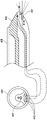
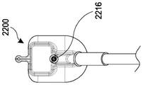
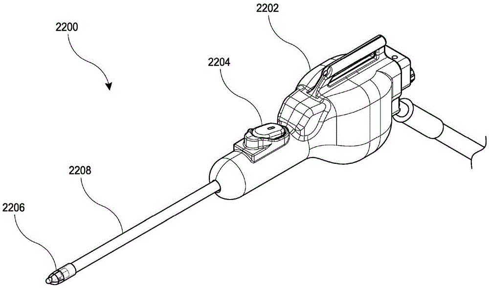
Fig. 22 illustrates an embodiment of a clot evacuation device.
Fig. 23 shows a perspective view of an optical guide.
Fig. 24A-24G illustrate an optical introducer and/or clot evacuation device. Fig. 24A shows a close-up view of the distal end of an optical guide inserted through an outer sheath. Fig. 24B shows a close-up view of the distal end of the clot ejection device inserted through the outer sheath. Fig. 24C shows a cross-sectional schematic view of the operational components within the elongate body of the clot evacuation device of fig. 24B. Fig. 24D shows a handpiece of the clot evacuation device with a portion of the housing removed. Fig. 24E shows a perspective view of a hand of a user holding a clot evacuation device. Fig. 24F shows a perspective view of a clot ejection device with a stripping sheath. Fig. 24G schematically illustrates coupling of a navigation system component to a clot evacuation device.
Fig. 25A-25C show close-up views of the distal end of a clot evacuation device having a windshield and an insertable introducer. Fig. 25A shows a clot evacuation device inserted into an optical introducer. Fig. 25B shows the clot evacuation device inserted into the introducer. Fig. 25C shows the clot evacuation device without the introducer inserted.
Fig. 26A-26I show examples of clot evacuation devices having a windshield and an insertable introducer. Fig. 26A shows a clot evacuation device inserted into an introducer. Fig. 26B shows the clot evacuation device without the introducer inserted. Fig. 26C shows a cross-sectional view from the distal end. Fig. 26D shows a perspective view of the clot evacuation device with the windshield removed. Fig. 26E shows a close-up view of a irrigation hypotube configured to clean a lens of a visualization device of a clot evacuation device. Fig. 26F-26I show various examples of windshields and atraumatic tips.
Fig. 27A-27E illustrate examples of a clot evacuation device and an insertable introducer having a balloon shielding member. Fig. 27A shows a close-up view of the distal end of a clot evacuation device inserted into an optical introducer. Fig. 27B shows a close-up view of the distal end of the clot evacuation device inserted into the introducer. Fig. 27C shows a close-up view of the distal end of the clot evacuation device without the introducer inserted. Fig. 27D and 27E illustrate another example of a clot evacuation device and an insertable introducer having a balloon shielding member. Fig. 27D is a close-up view of the distal end of the clot evacuation device. Fig. 27E is a side cross-sectional view of a clot evacuation device.
Fig. 28 schematically illustrates a side cross-sectional view of an alternative embodiment of a clot evacuation device having an insertable introducer and a balloon shielding member.
Fig. 29A-29G show various views of an example clot evacuation device.
Fig. 30 shows an example of a clot evacuation device.
Detailed description of the preferred embodiments
Embodiments of the present disclosure relate to devices, methods, and systems that provide clot evacuation devices and visualization (e.g., integrated clot evacuation devices with visualization) for neurosurgical applications, particularly for evacuating clots formed due to intracranial hemorrhage (ICH). In addition to or instead of clot ejection, the clot ejection devices disclosed herein may also be used as universal ejection devices for other applications, particularly neurovascular applications. For example, the evacuation device may be used to aspirate/evacuate blood, tissue, fluids, particles, debris, and/or other matter from the body. Before these embodiments are described in greater detail, it is to be understood that this application is not limited to particular embodiments described, as such may, of course, vary. It is also to be understood that the terminology used herein is for the purpose of describing particular embodiments only, and is not intended to be limiting, since the scope of the present disclosure will be limited only by the claims set forth herein or added or amended in the future. When a range of values is provided, it is understood that each intervening value, to the extent that there is no such stated, between the upper and lower limit of that range and any other stated or intervening value in that stated range, is encompassed within the disclosure. The upper and lower limits of these smaller ranges may independently be included in the smaller ranges, and are also encompassed within the disclosure, subject to any specifically excluded limit in the stated range. Where the stated range includes one or both of the limits, ranges excluding either or both of those included limits are also included in the disclosure.
Certain ranges are set forth herein wherein numerical values are preceded by the terms "about", "about" and "approximately". These terms are used herein to provide literal support for the specific numbers that follow, as well as numbers that are close or similar to the numbers that follow the terms. In determining whether a number is near or approximate to a particular enumerated number, the near or approximate noneenumerated number can be a number that is substantially equal in context to the specifically enumerated number.
All publications and patents cited in this specification are herein incorporated by reference as if each individual publication or patent were specifically and individually indicated to be incorporated by reference and were set forth in its entirety herein for the purpose of disclosing and describing the methods and/or materials associated with the cited publications. The citation of any publication is for its disclosure prior to the filing date and should not be construed as an admission that the present invention is not entitled to antedate such publication by virtue of prior invention. Further, the dates of publication provided may be different from the actual publication dates which may need to be independently confirmed.
It should be noted that, as used herein and in the claims, the singular forms "a," "an," and "the" include plural referents unless the context clearly dictates otherwise. It should further be noted that the claims may be drafted to exclude any optional element. Accordingly, this statement is intended to serve as antecedent basis for use of such exclusive terminology as "solely," "only," etc., or use of a "negative" limitation in connection with the recitation of claim elements.
It will be apparent to those skilled in the art upon reading this disclosure that each of the individual embodiments described and illustrated herein has discrete components and features which may be readily separated from or combined with the features of any of the other several embodiments without departing from the scope or spirit of the present invention. Any recited method may be performed in the order of the events listed or in any other order that is logically possible.
Also provided are kits for practicing the subject methods, wherein the kits can include one or more of the devices described herein in the specification, and/or components of the subject systems. In an embodiment, the components within the package are pre-sterilized. Further details regarding the pre-sterilization of packaging may be found in U.S. patent 8,584,853 filed on 2, 16, 2012, which is incorporated by reference herein in its entirety.
Fig. 1 illustrates an embodiment of a system 2 for visualization and drainage of a clot, such as the clot described above with respect to ICH. In some embodiments, the clot evacuation system 2 comprises: an integrated clot evacuation device 4 (described in more detail below), a controller 6, and a cable 8, the cable 8 providing electrical communication between the controller 6 and the integrated clot evacuation device 4. By integration, one skilled in the art will appreciate that the clot evacuation device may provide visualization and evacuation integrated into a single device.
In some embodiments, controller 6 may include a housing with a memory port such as SD card slot 10 (and/or optional USB) and camera buttons 12. The camera button 12 may activate the system to collect and/or store still or moving images. The controller 6 may also include a power button 14, a mode switch button 16, and a brightness control 18. The controller 6 may also include a display, such as a screen 19, for displaying still images and/or video.
Activation of the mode switch button 16 can switch the system between different modes, such as a program mode in which video and/or still images are collected and displayed in real-time on the video screen 19, and a consultation mode in which the clinician can selectively display stored images and video on the video screen 19 for analysis. For example, in program mode, the system may display video or images from the visualization sensor in real-time. Real-time means that the screen 19 can display video of the interior of the tissue site being explored by the clinician. The video and/or images may also be automatically stored by the system for later playback. As another example, while in the consultation mode, the screen 19 may conveniently display certain images or videos that have been previously acquired by the system so that the clinician can easily analyze the collected images/data and discuss the images and data with the patient. In some embodiments, the clinician may be able to annotate the image with a touch screen or other suitable means.
In some embodiments, the screen 19 may be any type of image plane suitable for visualizing images, such as an iPad, a camera, a computer monitor, a screen on a cell phone, or a display carried by a head-mounted support such as glasses or other head-up display. In some embodiments, the use of cables may be avoided by configuring the device and the display to communicate wirelessly.
In some embodiments, it may be desirable to remove the cable and instead provide a wireless communication link between the probe and the monitor, which may also lead to a centralized medical record storage and/or evaluation location. Local transmissions, such as with a monitor within a medical suite, may be implemented via a local area network, such as a "WiFi" network based on the IEEE 802.11 wireless local area network standard, the bluetooth wireless personal area network standard, or a low-power ANT wireless protocol. Transceiver chips and associated circuitry are well known in the art and may be located within the handpiece housing of the integrated clot evacuation device 4 discussed below.
In some embodiments, the clot evacuation device 4 of fig. 1 can be used in conjunction with a neuro-navigation system and/or other medical navigation systems. To support placement of the clot evacuation device, an access device may be used. The access device has properties that enable the clot evacuation device to be accurately positioned and fixed at a particular angle or range of angles relative to the skull. The access device may be part of the stereotactic frame, or it may be frameless, and thus fixed directly to the skull. Examples of such Frameless devices include, but are not limited to, "Navigus System for frame Access" and navorientation manufactured by Image-Guided neurology, incTMProduct, or Stealth StationTMIntraoperative guidance system (Medtronic Sofamor Danek, menfield, tennessee). Using a stereotactic frame or frameless access device, the clot evacuation device can be placed on the surface of the scalp, on the surface of the skull, inside the skull, or positioned over the skull. For frameless stereotactic, the user can select their matching points between Anatomical Landmarks (AL) or surface Fiducial Markers (FM) to define the alignment of the head in the physical and radiographic image space. To further facilitate positioning of the clot evacuation device within the head, fiducial markers may be placed on the clot evacuation device or a handle assembly comprising the clot evacuation device. In some implementations, navigation may be performed using detection devices such as motion sensors, accelerometers, and/or gyroscopes.
In certain embodiments, during clot drainage at a target site in the brain, the patient recovery status may be monitored using one or more sensing methods, such as, but not limited to, monitoring oxygen level or saturation, carbon dioxide production rate, heart rate, intracranial pressure, and/or blood pressure. In addition, the measurements of the sensing element can be used to modulate the strength, frequency, and/or duty cycle of the components of the clot evacuation device. Such a feedback process is also referred to as a closed loop control system. Some embodiments may also include the use of a Disposable Patient Interface (DPI), i.e., a sterile, compliant conductive gel/oil pack that interfaces between the ultrasound transducer and the patient.
Fig. 2A illustrates front and rear perspective views of an embodiment of an integrated clot evacuation device 1100 that may be used in the clot evacuation systems described above, including an elongate body 1102 and a handpiece 1104. The elongate body 1102 may have a length that is at least about 1.5 times longer than its width or diameter, at least about 2 times longer than its width or diameter, at least about 4 times longer than its width or diameter, at least about 10 times longer than its width or diameter, at least about 20 times longer than its width or diameter, at least about 30 times longer than its width or diameter, at least about 50 times longer than its width or diameter, or 50 times the width or diameter. The length of the elongate body 1102 can vary, and in some cases can be at least about 2cm long, at least about 4cm long, at least about 6cm long, at least about 8cm long, at least about 10cm long, at least about 15cm long, at least about 20cm long, at least about 25cm, at least about 50cm, or longer than 50 cm. The elongate body 1102 may have the same outer cross-sectional dimension (e.g., diameter) along the entire length. Alternatively, the cross-sectional diameter may vary along the length of the elongate body 1102. In certain embodiments, the elongate body 1102 is a tubular elongate body, and the outer diameter of the tubular elongate body is about 0.1mm to 10mm, about 0.5mm to 6mm, about 1mm to 4mm, about 1.5mm to 3mm, about 2mm to 2.5m, or about 2.1 mm. In some embodiments, the elongate body 1102 has a 14 gauge needle diameter, has an Outer Diameter (OD) of about 2.1mm and an Inner Diameter (ID) of about 1.6 mm.
In some embodiments, and as described elsewhere in the specification, the elongate body 1102 can have a proximal end 1106 and a distal end 1108. The term "proximal" as used herein refers to the end of the elongate body 1102 that is closer to a user (such as a physician operating the device in a clot drainage procedure), and the term "distal" as used herein refers to the end of the elongate body that is closer to the internal target tissue of the subject during use. In some cases, the elongate body 1102 is a sufficiently rigid structure to allow the distal end to be pushed through tissue when sufficient force is applied to the proximal end of the elongate body 1102. Thus, in certain embodiments, the elongate body 1102 is not flexible or pliable, at least not to any significant degree. In other embodiments, the elongate body 1102 is flexible and pliable, allowing the elongate body 1102 to twist and bend around tissue.
In some embodiments, the distal end 1108 will be open-ended to provide visualization, lighting, irrigation, and/or suction through the open end. The distal end 1108 may be blunt to prevent tissue damage. The elongate body 1102 can be used to traverse brain tissue to reach an object of interest, such as a clot. The device may provide visualization of tissue through the open end of the elongated body and display these images on a separate screen, as depicted in fig. 1 above.
In certain embodiments, any portion of the clot evacuation device, such as the outer portion of the elongate body and/or the inner hypotube, may be made of metal, polymer, or a combination of both in various configurations, including but not limited to tubular, oval, rectangular, or all combinations, as is known in the art. The pre-shaping feature of the distal end of the elongate body may be achieved using a shape memory alloy such as nickel titanium (NiTI) or a Shape Memory Polymer (SMP) (also known as a "smart" material) that can be switched between two shapes, from a fixed (temporary) shape to a predetermined permanent shape. Further, any combination of metals, shape memory polymers, or conventional polymers may be used to achieve the desired deflection characteristics. Shape memory polymers may include, but are not limited to, polyurethane or polystyrene. Such memory materials are beneficial when needed for devices that require deflection to access a desired treatment area in a space located outside the outer shaft. In some embodiments, the elongate body is made of a material that is flexible but resistant to torsion, thereby allowing the elongate body to flex in use.
As depicted in fig. 2A, in an embodiment, the handpiece 1104 may have a circular "clamshell" shape, including a seam 1110 connecting a clamshell top 1112 and a clamshell bottom 1114. In some embodiments, the clamshell top 1112 and bottom 1114 can be made in two pieces and then attached together at seam 1110. The circular clamshell shape provides a comfortable and ergonomic handle for a user to grasp when using the device. In some embodiments, and as will be described in greater detail subsequently, the handpiece may include an image capture control, such as a button 1116 configured to capture a desired image. In further embodiments, the image capture control may include a switch, dial, or other suitable mechanism. The handpiece 1104 may also include a retraction control 1118 that retracts or extends a portion of the elongate body 1102. The retract control 1118 will be described in more detail in conjunction with fig. 2B-2C and the figures that follow. In some embodiments, the handpiece 1104 can have a bayonet design.
In some implementations, control 1116 can selectively activate the capture of images and/or videos. Accordingly, control 1116 can be configured to selectively start video recording, stop video recording, and/or capture still images during video recording or when video recording is stopped. In an embodiment, these activities may be activated by voice and/or buttons on the tablet computer. In some embodiments, the second tablet computer/phone/screen may be stored in a sterile drape bag.
In an embodiment, the handpiece 1104 may include a luer connection 1120 configured to connect to any fluid source as described herein in this section or elsewhere in this specification, such as sterile saline. The luer connection 1120 may be in fluid communication with a lumen extending the entire length of the elongate body 1102, thereby allowing delivery of fluids or agents to the tissue site.
The interface between the handpiece 1104 and the elongated body 1102 may include a hub 1122 that connects the handpiece 1104 to the elongated body 1102. In some embodiments, hub 1122 may be detachable, allowing the elongated body to be detached from handpiece 1104. In other embodiments, the elongated body is permanently attached to the handpiece 1104 via the hub 1122 to provide an integrated assembly. Handpiece 1104 may also include a strain relief node 1124 configured to attach to a cable (not shown in fig. 2A). The strain relief nodes 1124 may be used to reduce strain on wires that may be in electrical communication with the handpiece 1104.
In some embodiments, the clot evacuation device 1100 is configured as a single use integrated assembly. The clot evacuation device 1100 may be pre-sterilized, so the combination of integration and pre-sterilization allows the clot evacuation device 1100 to be ready for use when removed from the packaging. After use, it can be disposed of. Thus, the handpiece 1104, the elongated body 1102, and other components such as cables may all be a single unit. A single unit means that the various parts described above can be attached together as a single piece and are not intended to be disassembled by the user. In some embodiments, the various parts of a single unit are inseparable without destroying one or more components. In some embodiments, a display as described herein in this section or elsewhere in this specification can also be incorporated and sterilized as part of a single unit clot evacuation device.
With respect to clot imaging, the method includes positioning the distal end of the elongate body 1102 in viewing relationship with a target tissue (e.g., a clot and/or brain tissue), and viewing the target tissue with a viewing and/or imaging assembly integrated into the clot evacuation device. Viewing relationship means that the distal end is positioned within 40mm, such as within 10mm, including within 5mm, of the object of interest. Positioning the distal end of the clot evacuation device relative to the desired target tissue may be accomplished using any convenient approach, including direct linear advancement from the percutaneous access point to the target tissue. After positioning the distal end of the clot evacuation device in an observed relationship with the target, the target is imaged by using an illumination element and a visualization sensor (such as described elsewhere in the specification) to obtain image data. The image data obtained according to the method of the invention is output to the user in the form of an image, for example using a monitor or other convenient medium as display means. In some embodiments, the image is a still image, while in other embodiments, the image may be a video.
In system embodiments involving a burr hole or other aperture in the skull to achieve access to the site of the clot, an endoscopically assisted micro neurosurgical device, commonly referred to as a trocar, may be used in any known manner in conjunction with embodiments of the devices and systems disclosed herein in this section or elsewhere in this specification. The clot evacuation devices disclosed herein in this section or elsewhere in this specification may be used in any of the channels of trocars, such as those described below. Trocars are used to help manage and control several devices commonly used in neurosurgery involving drilling. Examples of such commercial devices include, but are not limited to: MINOP trocar from Aescula, B.Braun (Melsungen, Germany) and channel trocar from Medtronic Inc. (Minneapolis, Minn.). Most conventional trocars have three or four channels. For example, a three-channel trocar has an elongated tube with a distal end and a proximal handle, two small channels (a flush channel and an overflow channel), and one larger channel to allow introduction of visualization and/or treatment devices therethrough. A four-channel trocar may have an elongated tube with a distal end and a proximal handle, with two small channels (irrigation and overflow channels) and two larger channels (for visualization devices such as scopes or ultrasound diagnostic devices, and another channel for therapeutic devices). In other examples, four-channel trocars allow neurosurgery procedures (such as ventricular fistulization, biopsy, and removal of cysts, blood clots, and other obstructions) to be performed under direct visualization simultaneously with endoscopic or diagnostic devices placed in the visualization channels. A three-channel trocar requires that the visualization device be first placed into the working channel to assess the treatment area and then removed so that the treatment device can be introduced through the same channel to perform the treatment procedure. The trocar is typically made of metal, but may be made of a polymer and may have any variable length between 100 and 400 mm.
Fig. 2B illustrates a cross-sectional side view of the embodiment of the clot evacuation device 1100 depicted in fig. 2A. As shown in fig. 2A, the clot evacuation device 1100 includes a number of components, such as an image capture trigger 1116, a retraction control 1118, a luer connection 1120, an elongate body 1102, a handpiece 1104, and a hub 1122.
Referring now to fig. 2C, in some embodiments, the handpiece 1104 may include a retraction control 1118. The retraction control 1118 may be used to retract the outer tubular body 1126 of fig. 3A relative to the hypotube 1128 (described in more detail below), thereby allowing the hypotube 1128 to extend beyond the front opening of the outer tubular body 1126 at the distal end 1108.
Fig. 3A illustrates a side cross-section of an embodiment of the distal end 1108 of the elongate body of fig. 2A-2C, with additional details not shown in fig. 2A-2C. The elongate body 1102 includes an outer tubular body 1126, which may be in the form of an elongate tube. The size of the outer tubular body 1126 may vary, but is preferably about 3.7mm in diameter. Visualization is provided by inner hypotube 1128, which inner hypotube 1128 extends concentrically through the outer tubular body. This inner hypotube 1128 may be used to transmit an image of the tissue site to a camera located in the handpiece 1104, or alternatively there may be a camera located at the distal tip of the inner hypotube 1128. The inner hypotube 1128 may also contain an illumination element 1134, such as an illumination fiber, to illuminate the target tissue. In some embodiments, the outer tubular body 1126 may be slid forward beyond the inner hypotube 1128 or retracted to extend the inner hypotube 1128 beyond the outer tubular body 1126. When the outer tubular body 1126 is slid into the forward position, as depicted in fig. 3A, visualization elements (e.g., cameras, lenses, and related components) in the inner hypotube 1128 may provide a field of view 3000 down a "tunnel" inside the hypotube 1128, which is schematically depicted in fig. 3A. Such a location may separate soft tissue from distal optics 1136 (such as a lens) and also allow sufficient distance for tissue at the distal tip to be in focus (see fig. 3A).
In some embodiments, the elongate body 1102 can include a deflection that can be transverse or lateral. The distal end of hypotube 1128 may extend laterally away from outer tubular body 1126. The degree or distance of deflection may be moved and adjusted as desired by further moving inner hypotube 1128 in any direction. In some embodiments, the handpiece 1104 can be rotated 360 degrees so that rotating the distal end 1108 of the elongate body 1102 will cause the distal portion to enter an area within more space. The distal end 1108 may be moved up and down within the patient's head, thereby deflecting the distal end 1108 into a wide range of space well beyond its original position.
In some embodiments, the distal end of the visualization element can include a distal lens 1136 configured to facilitate imaging of the internal tissue site. The distal lens 1136 or any other lens may create defects and imperfections during manufacture, resulting in image distortion. These distortions may be unique to a single lens and, therefore, may be unique to a single clot evacuation device 1100 with embodiments disclosed herein. Thus, to enhance image quality, the apparatus 1100 as depicted in FIG. 2A may include automatic optical correction in the form of a unique algorithm. In some embodiments, the algorithm may be stored in a chip or other suitable means within the handpiece 1104.
In some embodiments, automatic optical correction may be used to improve the quality of the image generated by the clot evacuation device 1100. The abbe number, also known as the V number or inverse dispersion coefficient (constringency) of a transparent material, is a measure of the dispersion of the material (change in refractive index with wavelength) in relation to the refractive index, with high V values indicating low dispersion (low chromatic aberration). It is desirable to have low color difference to optimize image quality, but achieving low color difference generally increases manufacturing costs. In some embodiments, color differences in the clot evacuation device may be corrected for clinical use by the software algorithms described above, which allows for economy during manufacture. For example, optical correction may enable visualization performance of devices with cheaper lenses to be compared to that of visualization devices using more expensive lenses with few imperfections.
In some embodiments, the optical correction may be generated by comparing the captured image to a known defined pattern and generating an algorithm that corrects for tissue visualization device-specific chromatic aberrations and image distortions of each. In some embodiments, the optical correction may be unique to a single tissue visualization device. In certain embodiments, additional information about the tissue visualization device may be stored, such as X, Y location of the lens center, image circle size, and unique characteristics of the LEDs, in order to provide a consistent initial light level. The above-described features of the clot ejection device and additional features described elsewhere in the specification may be determined during manufacture and stored in a computer memory, such as an electrically erasable programmable read-only memory (EEPROM). In an embodiment, the entirety of the handpiece 1104 and the elongated body 1102 may be an integrated unit. In certain embodiments, the handpiece 1104 further includes a retraction control 1118 configured to retract the elongate body 1102 so as to expose the distal lens 1136 of the optical hypotube 1128. In some embodiments, the handpiece 1104 may also include a luer connection 1120 configured to direct fluid to an internal tissue site via the lumen.
In an embodiment, to generate the algorithm at the point of manufacture, the distal optics 1136 are focused on a known defined pattern. The computer may then compare the captured image to the known pattern and generate an algorithm that restores the captured image to a truly defined pattern. The algorithm may then be stored in a chip in the handpiece 1104, as described above.
When the handpiece 1104 is connected to the display 6 at a clinical point, the algorithm serves as a basis for the display 6 to correct the captured image, as previously described with respect to fig. 1, to remove aberrations in the optical system. Each clot evacuation device 1100 will have a unique offset and therefore each handpiece 1104 will carry a unique algorithm designed to calibrate the system.
In some embodiments, the elongate body 1102 can be sized to slidably move through an internal passage of an access device, or directly through tissue without the use of an additional access device. In an embodiment, the length of the elongate body 1102 may be 1.5 times or more, such as 2 times or more, including 5 times or even 10 times or more, of its width, e.g., 20 times longer, 30 times or more, than its width. At least the distal end of the device may have a longest cross-sectional dimension of 10mm or less, such as 8mm or less, including 7mm or less, wherein in certain embodiments the longest cross-sectional dimension has a length of 5mm to 10mm, such as 6mm to 9mm, including 6mm to 8 mm.
In some embodiments, hypotube 1128 may be biased against the inner diameter of outer tubular body 1126. For example, the outer tubular body 1126 may include indentations on the outer tubular body 1126 or the hypotube 1128 that bias the OD of the hypotube 1128 against the ID of the elongate body 1102.
In certain embodiments, the outer tubular body 1126 is not retractable/extendable; instead, the outer tubular body 1126 and the inner hypotube 1128 have a fixed length. For example, the length of the inner hypotube 1128 may be the same as the outer tubular body 1126 or may be shorter such that the inner hypotube 1128 is offset inside the outer tubular body 1126. Alternatively, the inner hypotube 1128 may be biased against a side of the outer tubular body 1126.
In an embodiment, the distal end 1108 of the elongate body 1102 may include a deflection tip to allow mechanical means to change the viewing direction of the hypotube 1128 (such as about 5-6 degrees). In some embodiments, the viewing direction may be at least about 3 degrees, at least about 6 degrees, at least about 12 degrees, at least about 15 degrees, at least about 20 degrees, at least about 30 degrees, at least about 45 degrees, or greater than 45 degrees from the central longitudinal axis of hypotube 1128. A wide angle of view may be achieved with a lens or by rotating the fiber if the distal end is off axis.
In some embodiments, a lumen 1138 surrounds the inner hypotube 1128, as shown in fig. 3A, which can be used to provide suction to remove clots and/or to provide irrigation to clean the distal lens and/or break up clots. In some embodiments, irrigation may additionally or alternatively be provided along the lumen 1138 or by an outer sleeve surrounding the outer tubular body. Alternatively, irrigation may be provided along a separate channel within the outer tubular body 1102. In certain embodiments, the device can clean the distal lens 1136 using any of the flush modes described herein in this section or elsewhere in this specification.
In some embodiments, the clot evacuation device can further include irrigators and aspirators configured to irrigate internal target tissue sites and/or components of the device, such as the lens of the visualization sensor. Thus, the elongate body 1102 may also include one or more lumens that extend at least the general length of the device, e.g., for performing a variety of different functions, as outlined herein elsewhere in this section or specification. In certain embodiments, where it is desired to flush (i.e., wash) a target tissue site at the distal end of the elongate body 1102 (e.g., remove ablated tissue from the site, etc.), the elongate body 1102 can include both an irrigation lumen and a suction lumen. Accordingly, the clot evacuation device may include an irrigation lumen extending axially through the elongate body. During use, the flush lumen may be operably connected to a fluid source (e.g., a physiologically acceptable fluid, such as saline) at the proximal end of the device, wherein the fluid source is configured to introduce fluid into the lumen under positive pressure, e.g., within a pressure range of 0psi to 60psi, such that the fluid is delivered along the flush lumen and out the distal end. Although the size of the irrigation lumen may vary, in certain embodiments, the longest cross-sectional dimension of the irrigation lumen is in the range of 0.5mm to 5mm, such as 0.5mm to 3mm, including 0.5mm to 1.5 mm.
During use, the aspiration lumen (e.g., lumen 1138) may be operably connected to a negative pressure source (e.g., vacuum source) at the proximal end of the device. For example, the means for generating the extraction may include: vacuum pumps, hospital wall supplies (hospital wall supplies), hand-operated syringes, and/or foot-operated designs. Although the size of the aspiration lumen may vary, in certain embodiments, the longest cross-sectional dimension of the aspiration lumen is in the range of 1mm to 7mm, such as 1mm to 6mm, including 1mm to 5 mm. In some embodiments, the aspirator includes a port having a cross-sectional area that is 33% or greater, such as 50% or greater, including 66% or greater, of the cross-sectional area of the distal end of the elongate body. The device may alternatively use a large syringe operated by the assistant without wall extraction. In some embodiments, a battery powered vacuum pump and/or a foot operated pump integrated into the waste chamber may be used.
In some cases, the negative pressure source is configured to draw fluid and/or tissue from a target tissue site at the distal end into the suction lumen under negative pressure (e.g., a negative pressure in the range of 300mmHg to 600mmHg, such as 550 mmHg), such that the fluid and/or tissue is removed from the tissue site and transported along the suction lumen and out the proximal end, e.g., into a waste reservoir. In some embodiments, the irrigation lumen and the aspiration lumen may be separate lumens, while in other embodiments, the irrigation lumen and the aspiration function may be performed in a single lumen.
In some embodiments, the extraction should be increased beyond the wall extraction described above. For example, wall extraction may be used to pull clot material through the channels and ducts of the device, but it uses higher manual or pump-driven extraction to force clot into the device or to pressurize the occluded channel/duct. In some implementations, various controls may be used for flushing and pumping. For example, the controls may be located on the handpiece 1104, cable, tablet (physical button, voice activated soft button), and/or foot pedal. In some embodiments, a blood pressure cuff may be used to generate the draw.
However, a common problem that may occur during aspiration of the clot is that the clot becomes lodged in the cavity 1138, thereby preventing/limiting further irrigation and aspiration. To address these potential issues, in some embodiments, as depicted and described in fig. 3B, the inner hypotube 1128 including visualization elements (such as visualization sensors and lenses) may be vibrated to break up and remove clots that may get stuck in the lumen 1138. The handpiece 1104, as depicted in fig. 3B, above fig. 1, and/or in further detail below, can further include a vibration/oscillation actuator 1140 and/or a vibration/oscillation plate or motor 1142 capable of vibrating the inner hypotube 1128. In embodiments, inner hypotube 1128 may be configured to withstand vibration to prevent damage during vibration. As will be understood by those skilled in the art, any of the ports described herein elsewhere in this section or the specification (such as the suction port 1122) may be used for suction, irrigation, or both. As shown in fig. 3B, the outer tubular body 1126 may extend beyond the distal end of the inner hypotube 1128 with the visualization device, and may be retracted to effectively extend the visualization device beyond the outer tubular body 1126.
In some embodiments, as depicted and described in fig. 3C, the outer tubular body 1126 and/or the inner hypotube 1128 can be rotated relative to each other to further assist in dislodging the clot. The handpiece 1104 may include an integrated means to rotate the outer tubular body 1126. These means may include an internal motor and/or an external thumbwheel 1144 that may be manually rotated by the user. Figure 3D schematically depicts rotation of the outer tubular body 1126 with respect to the inner hypotube 1128 in a cross-section taken along the elongate body 1102, viewed in the direction indicated by arrows 3D-3D in figure 3C. As the outer tubular body 1126 rotates, the inner hypotube 1128 may remain in a random position within the outer tubular body 1126, thereby acting as a scraper to help remove clots that have become lodged in the lumen. The outer tubular body 1126 may be inserted through an outer protective sheath to protect body tissue during rotation. In some embodiments, the inner hypotube 1128 can also be configured to be rotatable in addition to or instead of the outer tubular body 1126.
In certain embodiments, as depicted in fig. 3E, the clot evacuation device 1100 may also include a second port 1146 for irrigation. The irrigation port 1146 may also be connected to an outer sleeve 1148 that overlaps the outer tubular body 1126 as described above to provide a path for irrigation between the outer diameter of the outer tubular body 1126 and the inner diameter of the sleeve 1148. The outer sleeve 1148 may comprise a rigid or semi-rigid tube. In an embodiment, the outer tubular body 1126 may be perforated to assist in removing the clot blocking material without introducing significant amounts of fluid into the surgical site. The spacing of the perforations may vary such that more perforations are near the distal end of the outer tubular body 1126 and less perforations are near the proximal end. Further, such as shown in fig. 3E, the distal end of the clot evacuation device 1100 can be shaped to direct fluid over the optical element to clear the lens and/or provide external irrigation to the clot. The outer sleeve 1148 may extend beyond the distal tip of the clot evacuation device 1100 and may include a tapered or beveled distal end to provide further passivation. Further, as described elsewhere in the specification, the distal end of outer sleeve 1148 with the irrigation element may be retracted or extended. The distal end of the outer sleeve 1148 with the irrigation element, when extended, can act as a guide into the soft tissue with minimal damage to the brain tissue. Retraction of the distal end of the outer sleeve 1148 with the flushing element may clear the end of the outer tubular body 1126 to open the extraction lumen. Using features that help break up clots that may become lodged within the suction lumen may help the user avoid having to remove the device to clear the clot intraoperatively, which requires reintroduction of the device and repositioning of the target tissue.
As described above, in certain embodiments, the elongate body 1102 can also include one or more infusion lumens 1138 that extend at least the general length of the device, e.g., for performing a variety of different functions. In certain embodiments where it is desired to flush (i.e., wash) the target tissue site at the distal end 1108 of the elongate body 1102 and remove excess fluid, the elongate body 1102 can include both an irrigation lumen and a suction lumen. During use, the flush lumen may be operably connected to a fluid source (e.g., a physiologically acceptable fluid, such as saline) at the proximal end of the device, wherein the fluid source is configured to introduce fluid into the lumen under positive pressure, e.g., within a pressure range of 0mmHg to 500mmHg, such that the fluid is delivered along the flush lumen and out the distal end.
Although the size of the irrigation lumen can vary, in certain embodiments, the longest cross-sectional dimension of the irrigation lumen is in the range of 1mm to 3 mm. During use, the suction lumen is operably connected to a negative pressure source (e.g., a vacuum source) at the proximal end of the device, wherein the negative pressure source is configured to draw fluid from the tissue site at the distal end into the irrigation lumen at a positive pressure, e.g., within a pressure range of 50mmHg to 600mmHg, such that the fluid is removed from the tissue site and transported along the irrigation lumen and output from the proximal end, e.g., into a waste reservoir. Although the size of the aspiration lumen can vary, in certain embodiments, the longest cross-sectional dimension of the aspiration lumen is in the range of about 1mm to 10mm, about 1mm to 4mm, about 1mm to 3mm, or less than 1 mm. Alternatively, a single lumen may be provided through which irrigation and/or suction may be achieved. In embodiments, the product package may include a single port stopcock as a means of controlling fluid flow. In certain embodiments, a stopcock or suitable valve may be integrated directly into the device. In further embodiments, more than one port or stopcock may be used, such as two ports and two stopcocks, three ports and three stopcocks, and so forth. In some embodiments, a three-way stopcock may be provided so that the clinician may "switch" between infusion and aspiration, or first and second fluid infusions, without the need to connect and reconnect the tubes.
Returning to fig. 3A, the elongate body 1102 may include an outer tubular body 1126, which may be similar to a hypodermic needle, such as a 14 gauge needle with the sharpened tip removed. However, in some embodiments (not shown), the distal end of the elongate body 1102 can include a sharp tip. The visualization element may be in the form of an inner hypotube 1128 that extends concentrically through the outer tubular body 1126. Hypotube 1128 may be used to transmit an image of the tissue site to a visualization sensor, such as the visualization sensors described elsewhere in this section and specification herein. In some embodiments, the distal tip of hypotube 1128 can include a visualization sensor.
In certain embodiments, as depicted in fig. 3F, a visualization sensor 1150, or any other type of sensor described elsewhere in this section and the specification herein (such as a glucose sensor), may be positioned as shown in the figures. For example, two sensors 1150 may be positioned on the back of the elongated body of hypotube 1128 or other visualization body, facing forward and rearward (left figure), facing sideways (i.e., perpendicular to the longitudinal axis of the elongated body) and forward (middle figure), and/or facing forward and sideways at an angle (right figure), in some examples for image integration. For example, the images from each sensor 1150 shown in the right figure may be stitched together to form a larger image with a wider field of view. As described elsewhere herein, hypotube 1128 may be capable of rotational, vibratory/oscillating, and/or translational motion.
Visualization sensors of interest are those that include a photosensitive component (e.g., an array of photosensitive elements that convert light into electrons) coupled to an integrated circuit. The integrated circuit may be configured to obtain and integrate signals from the photosensitive array and output image data, which may in turn be transmitted to an extracorporeal display configured to receive the data and display it to a user. The visualization sensor of these embodiments may be considered an integrated circuit image sensor.
The integrated circuit components of these sensors may include a variety of different types of functionality, including but not limited to: image signal processing, memory, and data transmission circuitry for transmitting data from the visualization sensor to a location outside the body, and the like. The miniature visualization sensor may further comprise a lens assembly consisting of one or more lenses positioned relative to the photosensitive assembly so as to focus the image on the photosensitive assembly. One or more lenses may be present in the housing, if desired. Specific types of miniature visualization sensors of interest include Complementary Metal Oxide Semiconductor (CMOS) sensors and Charge Coupled Device (CCD) sensors. The sensors may have any convenient configuration, including circular, square, rectangular, and the like. The visualization sensor of interest may have a longest cross-sectional dimension that varies according to a particular implementation, where in some cases the longest cross-sectional dimension (e.g., diameter) is 10.0mm or less, such as 6.0mm or less, including 3.0mm or less.
The visualization sensor of interest may be a front side illumination sensor or a back side illumination sensor and have a sufficiently small size while maintaining sufficient functionality to be integrated at the proximal end of the elongated body within the handpiece of the inventive device. Aspects of these sensors are further described in one or more of the following U.S. patents, the disclosures of which are incorporated herein by reference in their entirety: U.S. patent nos. 7,388,242; 7,368,772, respectively; 7,355,228, respectively; 7,345,330, respectively; 7,344,910, respectively; 7,268,335, respectively; 7,209,601, respectively; 7,196,314, respectively; 7,193,198, respectively; 7,161,130, respectively; and 7,154,137.
The distal end of the elongated body may be configured for frontal and/or lateral viewing as desired. In other embodiments, the elongate body may be configured to provide image data from both the front and sides, for example, where the main viewing axis from the distal end of the waveguide extends at an angle greater than about 2 degrees or 5 degrees or 10 degrees or 15 degrees or more relative to the longitudinal axis of the elongate body, as described in more detail below.
Depending on the particular device embodiment, the elongate body may or may not include one or more lumens extending at least partially along its length, as described above. When present, the diameter of the lumen may vary and may be used for a variety of different purposes, such as irrigation, aspiration, electrical isolation (e.g., of electrically conductive members such as wires), as a mechanical guide, and the like, as will be reviewed in greater detail below. When present, such lumens may have varying longest cross-sections, in some cases ranging from 0.5mm to 5.0mm, such as 1.0mm to 4.5mm, including 1.0mm to 4.0 mm. The lumen may have any convenient cross-sectional shape, as desired, including but not limited to circular, square, rectangular, triangular, semi-circular, trapezoidal, irregular, and the like. These lumens may be provided with a variety of different functions, including as irrigation lumens and/or aspiration lumens, as described in more detail below.
In certain embodiments, as described above with respect to fig. 2-3E, the clot evacuation device may include one or more illumination elements configured to illuminate the target tissue location such that the location may be visualized with a visualization sensor, e.g., as described above. Various different types of light sources may be employed as the illumination element, provided they are sized such that they can be positioned at or carry light to the distal end of the elongate body. The light sources may be integrated with a given assembly (e.g., an elongated body) such that they are configured relative to the assembly such that the light source elements cannot be removed from the remainder of the assembly without significantly compromising the structure of the assembly. As such, the integrated lighting elements of these embodiments are not easily removable from the remainder of the assembly such that the lighting elements and the remainder of the assembly form a coherent whole. The light source may be a light emitting diode configured to emit light of a desired wavelength range, or an optical transmission element, such as an optical fiber, configured to transmit light of a desired wavelength range from a location other than the distal end of the elongated body (e.g., a location at the proximal end of the elongated body within the handpiece) to the distal end of the elongated body.
In some embodiments, an imaging camera may be provided on the distal end of the clot evacuation device in combination with ultrasound, as is known in the art. Such electronic imaging cameras may have a light emitting source provided by a light emitting diode (LAD) or light delivered by fiber optics from an external source. The principle of operation is the same as for an endoscope, but in this case the camera is incorporated in a single device together with the ultrasound device. Examples of such suitable cameras include, but are not limited to, cameras from medigus. ltd, ome, Israel; OmniVision, Santa Clara, calif; clear Image Technology, elyrina, Ohio. Further details can be found in U.S. patent publication No. 2012/0330196A 1 entitled "Methods and Apparatus for Removing Blood bags and Tissue from the Patient's Head", filed on 7.9.2012, which is incorporated herein by reference in its entirety.
As with the visualization sensor, the light source may include an electrically conductive element, such as a wire or an optical fiber or fiber bundle, that extends the length of the elongated body to provide power and control of the light source from a location outside the body (e.g., an extracorporeal control device).
If desired, the light source may include a diffusing element to provide uniform illumination of the target tissue site. Any convenient diffusing element may be employed, including but not limited to a translucent cover or layer (made of any convenient translucent material) through which light from the light source passes and is thus diffused. In embodiments of the invention where the system comprises two or more lighting elements, the lighting elements may emit light of the same wavelength, or they may be spectrally distinct light sources, where "spectrally distinct" means that the light sources emit light of substantially non-overlapping wavelengths, such as white light and infrared light. In certain embodiments, a lighting configuration as described in U.S. patent publication nos. US20100121139a1 and US20100121142a1 (the entire disclosures of which are incorporated herein by reference) is present in the device.
In some embodiments, the devices of the embodiments described herein may include a linear mechanical actuator for linearly translating a distal element of the device (e.g., a tubular body surrounding a visualization element) relative to the visualization element. "Linear translation" refers to moving an element along a substantially linear path. The term "linear" as used herein also includes movement in a non-linear (i.e., curved) path.
In some embodiments, there is also an integrated articulation mechanism in the device that imparts steerability to the distal end of the elongate body and/or the distal end of the visualization element. "maneuverability" refers to the ability to manipulate or orient the visualization element, tissue modifier, and/or distal end of the elongate body as desired during a procedure, for example, by using a controller located at the proximal end of the device. In these embodiments, the device includes a manipulability mechanism (or one or more elements located at the distal end of the elongate body) that enables the desired distal assembly to be manipulated as desired via a proximal control. Thus, the term "maneuverability" as used herein refers to the ability of the mechanism to provide a manipulation function to the user, such as changing direction in a desired manner, such as by deflecting the primary viewing axis to the left, right, up, or down relative to the initial axial direction.
The steering function may be provided by a variety of different mechanisms. Examples of suitable mechanisms include, but are not limited to, one or more axially movable pull or push wires, tubes, plates, nets or combinations thereof made of suitable materials such as shape memory materials, wires, and the like. For example, one active deflection mechanism includes providing a plurality of transverse slots axially spaced along a first side of the outer tubular body 1126 within the distal segment. A second side of the outer tubular body 1126 within the distal segment opposite (i.e., 180 deg.) the first side acts as an axially incompressible ridge while the first side may be axially compressed, thereby creating a laterally deflected depression in the direction of the first side. Axial compression (or elongation) of the first side relative to the second side for inducing or eliminating curvature may be achieved by an axially movable control wire. The distal end of the control wire may be secured to the outer tubular body 1126 within the distal section 1108, preferably to the distal end of the distal section. The control wires extend proximally over the entire length of the outer tubular body 1126 to the proximal deflection control. Manipulating the control to proximally retract the control wire will collapse the transverse slot, thereby shortening the axial length of the first side relative to the second side, thereby deflecting the distal section.
In some cases, the distal end of the elongated body is provided with unique additional capabilities that allow the distal end to independently rotate about its longitudinal axis while the majority of the operating handle remains in a fixed position, as discussed in more detail below.
The range of the distal dominant visual axis joint of the present invention may vary, such as at least about 5, 10, 25, or 35 degrees or more from the dominant visual axis. The visualization element may be configured for rotation about its axis such that the entire angular range is accessible on either side of the probe axis, essentially doubling the effective viewing angle, for example, as described in more detail below. The joint mechanisms of interest are further described in published PCT application publication nos. WO 2009029639; WO 2008/094444; WO 2008/094439 and WO 2008/094436; the entire disclosure of which is incorporated herein by reference. The specific joint configurations of interest are further described below in conjunction with the figures.
In some embodiments, the distal end of the elongate body 1102 can rotate about its longitudinal axis while the majority of the operating handle remains in a fixed position. As such, at least the distal end 1108 of the elongate body 1102 can be rotated to some extent while the handle attached to the proximal end of the elongate body 1102 remains in a fixed position. The degree of rotation in a given device may vary and may range from 0 to 360 degrees, such as 0 to 270 degrees, including 0 to 180 degrees.
As described herein elsewhere in this section and specification, in certain embodiments, the device may be disposable or reusable. As such, the devices of the present invention may be fully reusable (e.g., are multi-use devices) or fully disposable (e.g., all components of the device are single-use). In some cases, the device may be fully limited reusable (e.g., where all components may be reused a limited number of times). Each component of the device may be individually single-use, have limited reusability, or be infinitely reusable, resulting in an entire device or system consisting of components with different usability parameters.
As described elsewhere in this section and the specification herein, in certain embodiments, the devices of the present invention may be manufactured using any convenient material or combination thereof, including but not limited to: a metal material such as tungsten, a stainless steel alloy, platinum or an alloy thereof, titanium or an alloy thereof, molybdenum or an alloy thereof, nickel or an alloy thereof, or the like; polymeric materials such as polytetrafluoroethylene, polyimide, PEEK, and the like; ceramics, such as alumina (e.g. STEATITE)TMAlumina, MAECORTMAlumina), and the like. In some embodiments, materials that provide structural and light pipe properties may be used.
As summarized above, some embodiments of the invention include a visualization sensor and a lighting element. In certain embodiments, these visual sensors are positioned within the handle at the proximal end of the device. The system may include one or more visualization sensors at the proximal end of the device and one or more illumination elements located between the distal and/or proximal ends of the elongate body. In particular embodiments, one or more visualization sensors, such as those described in this section or elsewhere in the specification, may be located at a distal end of the device, such as within a distal end of the elongate body. In some embodiments, one or more visualization sensors may be located at various locations within the elongate body, such as approximately one-quarter the length of the elongate body from the distal end, one-half or three-quarters the length of the elongate body from the distal end. In certain embodiments, the visualization sensors may be miniaturized such that they do not substantially increase the outer diameter of the elongated body.
Similarly, in embodiments, one or more illumination elements may be located at the distal and/or proximal ends of the elongate body. Embodiments of the systems also include those wherein one illumination element is located at the distal and/or proximal end of the elongate body and another illumination element is located at the distal and/or proximal end of the access device. Further, embodiments of systems include those in which one or more illumination elements are located at the proximal end of the device and light is propagated through a waveguide, such as a fiber optic bundle, toward the distal end of the device. The longest cross-sectional dimension of the elongate body is typically 20mm or less, 10mm or less, 6mm or less, such as 5mm or less, including 4mm or less, and even 3mm or less.
Fig. 4 depicts a cross-sectional top view of an embodiment of a clot evacuation device 1100. Handpiece 1104 includes an illumination element 1134 and a visualization sensor support 1136, described in more detail below. Similar to the illumination elements or devices described elsewhere in this specification, the illumination elements 1134 may extend along the length of the elongate body 1102 and deliver light along the elongate body 1102 to the internal tissue site to allow visualization of the target tissue. In some embodiments, the illumination element 1134 comprises one or more bundles of illumination fibers.
Fig. 5A illustrates a cross-sectional view of a clot evacuation device embodiment along the length of an elongate body 1200, the elongate body 1200 being similar to the elongate body shown in fig. 1-4. In certain embodiments, the hypotube 1204 may include an image guide 1202 (which may be enclosed in one or more layers of a tube), at least one illumination fiber or fiber bundle 1210, an infusion lumen 1206, and an outer tubular body 1208. As will be understood by those skilled in the art, the use of the term "illumination fiber" herein includes an illumination fiber or fiber bundle. As described elsewhere in the specification, the illumination fiber or fiber bundle may be configured for transmitting for visualization a wavelength of light suitable for illuminating the target tissue; however, the illumination fibers may also be configured to transmit UV and/or infrared light to the tissue site. For example, if there are a total of 14 illumination fibers or fiber bundles, then 7 may be configured to deliver light suitable for visualization, while another 7 may be suitable for delivering UV light. However, any suitable combination may be used. For example, most of the illumination fibers, half of the illumination fibers, or less than half of the illumination fibers may be UV delivering. In particular embodiments, the number of illumination fibers may be increased or decreased relative to the number depicted in fig. 5. For example, there may be 1 fiber, at least 2 fibers, at least 5 fibers, at least 10 fibers, at least 14 fibers, at least 20 fibers, at least 25 fibers, at least 50 fibers, or greater than 50 fibers. In some embodiments, the illumination fibers may be configured to output light of a plurality of wavelengths suitable for imaging the internal tissue site.
The wavelengths of light delivered by the illumination fibers 1210[ which may be at least 4,8, 12, or more fibers or fiber bundles, and may be arranged in a ring configuration around the image-guide 1202, as shown in fig. 5A but described in detail below ] may be selected for various wavelength-specific applications. For example, wavelengths in the UV and/or infrared range may be utilized to allow visual differentiation of tissue types, such as to differentiate neural tissue from surrounding tissue and/or minimally vascularized neural tissue. The blood vessels may appear to have a first color (such as red) and the nerve tissue may appear to have a second color (such as blue). The wavelength can also be optimized to distinguish neural tissue from blood.
Another wavelength specific application involves directing a preselected wavelength to a target impregnated with a drug or prodrug. The drug is released after delivery of the preselected wavelength to the target, or the precursor is converted to the drug and then the drug is released. The target may be any one or combination of an implanted bolus or device, or an infused carrier medium, such as a liquid, gel, or bead.
The UV light may include ultraviolet a (long wave or black light), abbreviated "UVA", having a wavelength of 400nm to 315 nm; near UV light, abbreviated as "NUV", having a wavelength of 400nm to 300 nm; ultraviolet B or medium wave, abbreviated as "UVB", having a wavelength of 315nm to 280 nm; medium UV light, abbreviated "MUV", having a wavelength of 300nm to 200 nm; ultraviolet C (shortwave or germicidal), abbreviated as "UVC", having a wavelength of 280nm to 100 nm; far UV light, abbreviated as "FUV", having a wavelength of 200nm to 122 nm; vacuum UV light, abbreviated as "VUV", having a wavelength of 200nm to 400 nm; light UV light, abbreviated as "LUV", having a wavelength of 100nm to 88 nm; ultra-UV light, abbreviated as "SUV", having a wavelength of 150nm-10 nm; and extreme UV light, abbreviated as "EUV", having a wavelength of 121nm to 10 nm. In some embodiments, the catheter may include an element that emits visible light. The visible light may include violet light having a wavelength of 380-450 nm; blue light having a wavelength of 450-475 nm; cyan light having a wavelength of 476-495 nm; green light having a wavelength of 495-570 nm; yellow light having a wavelength of 570-590 nm; orange light having a wavelength of 590-620 nm; and red light having a wavelength of 620-750 nm. In some embodiments, the catheter includes an element that emits light having a wavelength between about 300nm and 500 nm. In particular, the conduit may include elements that emit light having a wavelength associated with blue light (e.g., light having a wavelength of about 450-475 nm). Wavelength selection information and characterization and other details related to infrared endoscopes are found in U.S. patent No. 6,178,346; U.S. patent application publication No. 2005/0014995 and U.S. patent application publication No. 2005/0020914, each of which is incorporated by reference herein in its entirety.
In certain embodiments, the outer diameter of hypotube 1204 may be in the range of about 0.1mm to 0.3mm, about 0.5mm to 2.5mm, or about 1mm to 2 mm. In some embodiments, the external diameter of hypotube 1204 is about 1.27 mm. In some embodiments, the inner diameter of the outer tubular body 1208 is in a range of about 0.1mm to 10mm, about 0.2mm to 8mm, about 0.5mm to 6mm, about 1mm to 5mm, about 1.2mm to 4mm, or about 1.4mm to 3 mm. In certain embodiments, the inner diameter of the outer tubular body 1208 is about 1.6 mm.
In some embodiments, the image guide 1202 allows for viewing of an image of the tissue site through a visualization sensor in the handpiece. In particular embodiments, the image guide may be an optical fiber or other suitable medium to allow imaging of the tissue site by a visualization sensor as described herein in this section or elsewhere in the specification. Depending on the desired properties, the fiber optic bundle may have at least about 6K, or at least about 10K or at least about 15K or at least about 30K or more fibers. In some embodiments, the image fibers may be 6.6k fiber bundles or 10k fiber bundles.
Fig. 5B-5F depict and depict embodiments of the distal end of a clot evacuation device that is similar to the device depicted in fig. 1-5A. However, in these embodiments, the visualization element may be positioned at a different location than depicted in fig. 2. The hypotube 1204 may be a visualization channel 1205 in the outer tubular body 1208. For example, in these embodiments, the visualization channel 1205 is incorporated with the outer tubular body 1208 and extends along the length of the elongate body. In some embodiments, additional channels 1207 may also extend along the outer tubular body 1208 to provide flushing in the form of a saline "jet" flush. In some embodiments, such as shown in fig. 5B and 5C, a visualization channel 1205 including an optical element, such as hypotube 1204, is incorporated with the outer tubular body and positioned on the inner surface of the outer tubular body 1208. In some embodiments, such as shown in fig. 5D, the visualization channel 1205 is incorporated with the outer tubular body 1208, but is positioned outside the diameter of the outer tubular body 1208. In some embodiments, such as shown in fig. 5E, visualization channel 1205 is incorporated with outer tubular body 1208, but is positioned internally between the inner and outer diameters of outer tubular body 1208. As shown in fig. 5F, retraction of a visualization element (e.g., hypotube 1204) into visualization channel 1205 can position a distal end of the visualization element near a "fluid jet" (e.g., a saline jet) in order to wash fluid on the surface of the visualization element. The injection may be angled downward by a post-mold machine operation. While these concepts may limit the size of the working channel (e.g., visualization channel 1205 disposed on the inner surface of outer tubular body 1208) or cause the cross-section of outer tubular body 1208 translated through tissue to be non-circular or asymmetric (e.g., visualization channel 1205 disposed on the outer surface of outer tubular body 1208), the impact of these configurations may be mitigated. For example, the working channel of the outer tubular body 1204 may be used for draining and/or flushing, thereby eliminating the need to insert any additional instruments through the working channel.
Fig. 5G-5M depict and depict embodiments of clot evacuation devices that are similar to the devices depicted in fig. 1-5B. For example, hypotube 1204 including visualization elements (e.g., imaging, illumination, non-visible wavelengths such as IR, UV, etc.) may be positioned in the center of outer tubular body 1208 (fig. 5G), against the inner wall of outer tubular body 1208 (fig. 5H), or outside of outer tubular body 1208 (fig. 5I). In certain embodiments, as described above and schematically depicted in fig. 5J, hypotube 1204 can be retracted to interact with a cleaning station to wipe, flush, and/or blot the lens or view tissue in a "tunnel view" if the soft tissue interferes with visualization. In the "normal" unsheathed position, hypotube 1204 may extend to be flush with outer tubular body 1208, or may extend distally beyond outer tubular body 1208, as schematically depicted in fig. 5K. In certain embodiments, as described elsewhere in the specification, an outer sleeve 1212 may be applied around outer tubular body 1208 to provide irrigation to the target tissue and/or tissue clot and/or lens for cleaning. The outer tubular body 1208 may include irrigation inlets 1209 spaced longitudinally and/or circumferentially around the elongate body. The outer sleeve 1212 may include one or more irrigation channels 1213, as shown in fig. 5L and 5M, for each irrigation inlet 1209 to direct irrigation fluid. The outer sleeve 1212 may be rotated about the outer tubular body 1208 to provide fluid to different irrigation channels 1213.
Fig. 6A-6C illustrate embodiments of the elongate body and internal components of the clot evacuation device 1300, which are similar to embodiments described herein elsewhere in this section or specification. In these particular figures, the housing of the handpiece is removed to better view the interior of the device. In some embodiments, the clot evacuation device includes an elongate body 1302, an illumination element 1304 (in some embodiments, the illumination element 1304 may be replaced by a cable, such as when an LED is positioned at the distal end of the elongate body 1302), a light source housing 1306, a printed circuit board 1310, a proximal lens housing 1308, a ferrule 1314, a nosepiece 1312, and a distal lens 1316.
Fig. 6B shows a top view of the visualization complex (without the illumination element) of the clot evacuation device 1300 of fig. 6A, while fig. 6C shows a side view. The components in these figures are similar to those shown in fig. 6A, but in fig. 6C, the visualization complex is identified as 1318. The visualization complex 1318 and surrounding components can be viewed in more detail in fig. 7.
Fig. 7 illustrates a cross-sectional side view of an embodiment of the visualization complex of fig. 6C. In some embodiments, visualization complex 1318 may include visualization sensor 1320, such as those described herein in this section or elsewhere in the specification. In certain embodiments, the visualization sensor 1320 may be a CMOS sensor as described herein in this section or elsewhere in the specification. However, as described elsewhere in the specification, the visualization sensor 1320 may be located at the distal tip of the inner hypotube.
In certain embodiments, visualization complex 1318 may include first lens 1322, optical aperture 1324, and second lens 1326. In some embodiments, the orifice may have a diameter of at least about 0.1mm, at least about 0.2mm, at least about 0.3mm, at least about 0.5mm, or greater than 0.5 mm. Preferably, the orifice may be about 0.222 mm. To support the lenses, visualization complex 1318 may include a proximal lens housing 1308 as previously described, where proximal lens housing 1308 may be used to secure lenses 1322 and 1326 in place and orientation. Visualization complex 1318 may also include an image guide 1328, similar to that previously described with respect to fig. 5A.
As shown in fig. 1 and 8A, one result of the integrated visualization device of the present invention is that rotating the visualization device 4 about the central longitudinal axis to achieve an enlarged field of view will simultaneously cause a significant rotation in an up-and-down orientation as seen by the clinician on a display, such as the video screen 19 of fig. 1 or the image 1501 of fig. 8A. It may therefore be necessary to compensate so that the patient reference direction will always appear at the top of the screen 19, as above, regardless of the rotational orientation of the visualization device 4, as depicted in the image 1503 of fig. 8B.
This may be achieved by including one or more sensors or switches carried by the clot evacuation device 4 that are capable of generating a signal indicative of the rotational orientation of the visualization sensor 1132. Signals may be transmitted to the controller 6 via wired or wireless protocols for processing and correcting the rotational orientation of the image on the screen 19 or other display to stabilize the image.
Suitable sensors may include simple tilt sensors or orientation sensors, such as mercury switches, or other systems capable of determining rotational orientation relative to an absolute reference direction (such as up and down). Alternatively, the rotational orientation image correction system may include a 3-axis accelerometer with associated circuitry, such as a small accelerometer constructed using MEMS (micro-electro-mechanical systems) technology, which uses capacitance measurements to determine the amount of acceleration, available from Freescale Semiconductor, Inc. (Austin, Texas) and others.
Instead of or in addition to an accelerometer, the visualization device may carry a gyroscope, such as a three-axis gyroscope. The gyroscope outputs may be the rate of change of roll angle, pitch angle, and yaw angle, and the rate of rotation measurements provided by the gyroscope may be combined with the accelerometer measurements to provide a complete six degree of freedom description of the motion and position of sensor 1132, although simply correcting for rotational orientation may not require this description. Controls may be provided on the handpiece 4 or controller 6 allowing the clinician to select what reference orientation they wish to appear on top of the screen (e.g., above, below, true up or true down, etc. the patient, or true sensor view such that the image on the screen rotates with the sensor), regardless of the sensor orientation. In some embodiments, markers such as arrows or lines may be projected onto the image to further identify different orientations and/or directions.
In some embodiments, the hypotube may be sleeved in a heat shrink tube. For example, the outer tubular body as described elsewhere in the specification may be constructed of a heat sensitive material. Thus, to construct an elongate body as described elsewhere in the specification, hypotubes and other components may be extended along an oversized outer tubular body which is then reduced to the diameter of the hypotube by means such as heat, UV, chemicals or other means. In contrast, conventional endoscopes and some of the endoscopes described elsewhere in the specification house the optics in a rigid stainless steel tube. However, housing the optics within a stainless steel tube may require forcing many optical and illumination fibers along a very tight inner diameter and then applying an adhesive such as epoxy. Such a process is difficult and expensive.
In some embodiments, the desired viewing direction may be achieved by positioning a prism at the distal end of the elongated body. Such prisms may provide viewing directions as disclosed elsewhere in the specification, for example: providing a viewing direction of 30 degrees from the axis of the elongated body. In some embodiments, the angle may be much smaller, such as between 0-15 degrees. In further embodiments, the angle may be in the range of 15-45 degrees. In some embodiments, the angle may be at least 45 degrees, at least 60 degrees, at least 75 degrees, or at least 90 degrees or greater.
In some embodiments, the elongated body may be non-circular in shape. For example, the entirety of the elongated body may be oval or elliptical. In some embodiments, only the distal end of the elongate body is oval-shaped, while the remainder of the elongate body is circular. The oval elongated body advantageously allows additional space for the deflected distal tip. In some embodiments, the major axis of the ellipse is about 1.1 times the minor axis. In some embodiments, the major axis is at least 1.2 times, 1.3 times, 1.5 times, 1.75 times, 2 times, 3 times, 4 times, 5 times, or greater than 5 times the minor axis.
In certain embodiments, the distal tip of the elongate body can be constructed of an elastic material to allow the distal tip to flex distally. Furthermore, the deflection portion of the distal tip may be very short, allowing the deflection portion to remain within the outer circumferential limits of the elongate body.
In some embodiments, the distal end of the elongate body may be rotatable relative to the hypotube. For example, the elongate body may include a sharp distal point, which may be below the hypotube, above the top of the hypotube, or on the side of the hypotube. In certain embodiments, the hypotube can serve as a shield to prevent a sharp distal point from injuring surrounding tissue in any direction. In certain embodiments, the hypotube may include a shield at the distal tip for protecting surrounding tissue from the sharp distal tip of the elongate body. As the hypotube is rotated, the shield may be moved away from the sharp distal tip of the elongate body, allowing further penetration of tissue.
Fig. 9A illustrates an embodiment of the distal end of a clot evacuation device, similar to that depicted in fig. 1-8B. Here, arrow "C" indicates a distal direction toward the tissue site. The distal end of the elongate member 105 includes an optical fiber 103, similar to the hypotubes and optical elements described elsewhere in the specification. Distal lens 102 may include any type of lens described herein in this section or elsewhere in the specification, including GRIN (gradient index) lenses. The lens may have a diameter of about 100-700 microns, about 200-600 microns, about 400-500 microns, or about 465 microns.
In some embodiments, as shown in fig. 9A, the distal end of the clot evacuation device may include a circular transparent plate 112, such as a glass plate or other suitable transparent material. In the embodiment depicted in fig. 9A, the board is non-powered, but in some embodiments, the board may be powered to have a magnification level of about 2x, 4x, 10x, 20x, 100x, or greater than 100 x. The plate may be flat on both sides, rounded on both sides, or rounded on one side and flat on the other. In some embodiments, the plate 112 may have a diameter of about 100-700 microns, about 200-600 microns, about 400-500 microns, or about 465 microns. In some embodiments, an adhesive 111 adheres the plate to the distal lens 102, and the distal lens 2 is adhered to the optical fiber 103 by another adhesive 111.
In an embodiment, and as depicted in fig. 19A, the plate 112 may include a mask 113 on a proximal side of the plate 112, which surrounds a transparent window 114. However, in some embodiments, the mask 113 may be on the distal side of the plate 112. By placing the mask 113 on the proximal side of the plate 112, interaction of potentially toxic mask material with tissue is prevented. The mask 113 may comprise any suitable material that limits light transmission, such as a chrome coating. However, any suitable evaporative coating may be used, such as different metallic materials.
The window 114 includes a region of the plate not covered by the mask 113, thereby allowing light to pass through the window 114. As described in more detail below with respect to fig. 12, a mask may be applied in the annular region of the plate 112, thereby creating a circular window 114.
In a particular embodiment, the mask 113 is used to limit the transmission of light through the plate 112. For example, the mask may limit the concentration of light at all angles reflected from the object being viewed (e.g., tissue site). Thus, the overlap of light rays on the image is very small, resulting in a sharper image over a wider depth of field. Although this may reduce the brightness of the image, the image is sharper. In certain embodiments, the material of the mask allows at most about 0%, about 2%, about 4%, about 5%, or about 10% of the light to be transmitted through the material. Furthermore, the mask preferably absorbs light rather than reflected light to limit stray light from affecting the sharpness of the image. In embodiments, the material of the mask may reflect at most about 0%, about 5%, about 10%, about 20%, about 25%, or about 30% of the light affecting the surface. In some embodiments, the reflectance for 400nm light may be 12%, 20% at 500nm, 27% at 600nm, and 33% at 700 nm.
The circular plate 112 may be sized to have the same diameter as the lens 102, however, in embodiments, the plate 112 may be smaller than the lens 102, such as at least about 10%, 25%, 50%, 75%, or 90% of the size of the lens 102. When the plate 112 is smaller than the lens 102, light may leak through the plate 112 into the lens 102, so in these cases an opaque adhesive or cap may be applied to the distal end of the lens 102 to restrict light from entering the lens 102. In some embodiments, the plate 112 may be non-circular, such as rectangular or polygonal. As with the circular plate, the non-circular plate may be 10%, 25%, 50%, 75%, or 90% of the lens size. As with the smaller circular plate, the uncovered area of the lens 102 may be coated with an opaque adhesive to limit light transmission.
In some embodiments, instead of using a transparent plate 112 with a mask 113, the plate 112 may be replaced with any suitable material comprising apertures. For example, a metal plate with a window, or an opaque polymer material may be used.
Typically in the imaging region, when using GRIN lenses (such as those described herein in this section or elsewhere in the specification), an optical mask such as that described above with respect to the plate will typically be placed between two GRIN lenses or at the focal point of the lenses. Here, however, the mask is positioned between the non-power supply plate and the power supply lens. Furthermore, although the mask may be placed at the focal point of the lens, here the mask need not be located at the focal point.
Fig. 9B shows a side view and a front view of an embodiment of a clot evacuation device, which is similar to the embodiments described above. In further embodiments, the CMOS/CCD sensor may be located at the distal tip of the visualization device rather than at the proximal location. With the distally mounted sensor, the distally located LED can be used with or without the short light pipe, rather than relying on the illumination fiber to transmit light from the proximal LED.
Fig. 9C shows a view along an elongate member of a visualization device such as depicted in fig. 5A. The illumination fibers 210 are secured within the epoxy 209 around the central optical element and/or the image guide 202. In some embodiments, the illumination fibers 210 may also be bundled on one side of the tubular body 204 with the imaging lens and fibers on the opposite side (the figures show them around the circumference, but they may also be asymmetric).
Fig. 10 compares pictures of the interior of the paprika imaged with the visualization device comprising the above plate (right) and the visualization device without the plate (left). As shown in the image, adding the plate greatly improves the sharpness of the image.
Fig. 11 depicts a plate 2000, such as the plate described above with respect to fig. 9A-9C. Here, the mask 2002 is annular and surrounds a transparent window 2004 that allows light to pass through. Although the mask 2002 and the window 2004 are depicted here as being annular, in other embodiments, the mask 2002 and the window 2004 may be in the form of a rectangle, triangle, octagon, or other suitable polygon. In certain embodiments, the mask 2002 may cover up to about 25% of a single-sided surface of the plate, about 50%, about 60%, about 70%, about 80%, about 90%, or about 95% of the surface area of one side of the plate 2000. In some embodiments, as described above, the plate 2000 can have a diameter of about 0.5mm or any of the diameters described above, however, the window 2004 can have any suitable diameter corresponding to the percentages described above, for example, the window 2004 can have a diameter of about 50-200 microns, 75-150 microns, or about 100-125 microns. For example, the diameter may be 90 microns, 130 microns, or 150 microns.
In certain embodiments, the ratio of the diameter of the active area of the imaging element/imaging fiber to the diameter of the window 2004 can be approximately at least about 2x, about 3x, about 4x, about 5x, about 6x, about 8x, about 10x, or greater than 10 x. In certain embodiments where the window 2004 is non-circular, the ratio of the area of the window 2004 to the effective area of the imaging element or imaging fiber may be at least about 5x, about 10x, about 15x, or about 20 x.
In certain embodiments, the distal end of the hypotube may be flared to accommodate a larger sensor than would ideally fit within the diameter of a standard hypotube. Such flaring can be as simple as a larger diameter cross-section, a square cross-section, or a condition that matches the contents therein. This flared axial length will accommodate the length of the path of the sensor plus the illumination fiber around the sensor, and will have a transition back to the circular cross-section of a normal hypotube. In embodiments, such an arrangement provides a lumen between the inner diameter of the outer tubular body and the outer diameter of the inner hypotube, which may provide an outlet/inlet when the flared portion of the inner hypotube extends distally past the tip of the outer hypotube. In some embodiments, this may be achieved by a non-circular cross-section. The distal end of the outer tubular body may also be flared with or without clearance to provide a lumen between the outer diameter of the hypotube and the inner diameter of the elongate member, as described above. In some embodiments, an indentation may be provided on the outer tubular body to guide the biasing of the inner hypotube. The inner hypotube may also be bent or biased against the outer tubular body. The biasing against the outer tubular body may also provide passivation of the edges of the outer tubular body.
Fig. 12A depicts an embodiment of a clot evacuation device, which is similar to the clot evacuation device depicted above with respect to fig. 1-3D. Here, the distal end or elongated member comprises an optical trocar concept — a transparent bulb that allows visualization through a transparent and conical distal end or window 3001 (also referred to as an obturator or introducer). The conically shaped distal end may be part of a larger optical trocar through which the clot evacuation device passes, or, as described below, may be a conically shaped distal end attached to the distal end of the clot evacuation device. In some embodiments, the distal end 3001 may be removably attached to the clot evacuation device, in which case the clot evacuation device may be inserted with the distal end 3001 attached to place an outer sleeve, removed to disconnect the distal end 3001, and reinserted without the distal end 3001 to operate the clot evacuation device, as described elsewhere herein. In some embodiments, the distal end 3001 may be configured to open (e.g., as petals or similar jaws) to allow manipulation of the clot evacuation device through the opening, as described elsewhere herein. Such an arrangement with a transparent distal end 3001 provides visualization while the clot evacuation device traverses the brain tissue to reach the clot. For example, the transparent and conical distal end 3001 may allow visualization of the transition from white brain matter to red clots to ensure that the clot evacuation device does not damage or tear brain matter as it navigates through the brain. In embodiments involving a sheathed needle, a second, separate device may then be used for aspiration/visualization. For example, the distal end 3001 may be attached to or integrated with a separate introducer device from the clot evacuation device. The introducer may be used to place an outer cannula or trocar, removed, and replaced with a separate clot evacuation device within the outer cannula or trocar to perform the clot evacuation procedure, as described elsewhere herein.
In certain embodiments, similar to the concepts described above, a visualization component of the integrated clot evacuation device may be integrated into the tapered distal window of the transparent tip. In embodiments, the distal window may be configured to open like a petal and allow a device assembly, such as an inner hypotube or an outer tubular body, to extend and/or retract forward. In some embodiments, as described above, the optical trocar may contain a separate clot evacuation device as described above, but with only a visualization assembly for visualization during insertion, which is subsequently removed from the transparent trocar after reaching the target site. The trocar would then be removed from the cannula/portal, leaving a complete portal to the target site. Next, a second or the same integrated clot evacuation device (with integrated aspiration) will then be inserted along the inner diameter of the cannula for aspiration/visualization of the clot. The trocar with visualization may also include additional features, such as: an illumination fiber (visible light or UV or IR or some other useful wavelength), an ultrasound transducer (to "view" through the tissue), a glucose sensor, or some other type of sensor that would have clinical benefit during the step of traversing the tissue.
In some embodiments, visualization may be incorporated into a cross-section of a cannula/portal with optional enhancements such as those described above (additional lighting, additional sensors, etc.). The distal end of the cannula may be flat or angled. If angled, the beveled tip "point" of the cannula can hold the visualization element and provide better visualization during the traversing step, as it will be the most distal element. In further embodiments, a second separate suction device may be used to remove the clot, or alternatively, an integrated suction/visualization device may be used, thereby providing two different views of the clot site.
In some embodiments, the navigation probe is configured to be inserted within the conically shaped transparent distal end. A locking member may also be provided that is operable to retain the navigation probe within the obturator. Further details regarding navigation probes can be found in U.S. patent publication 2014/0171873, which is incorporated herein by reference in its entirety.
As is known in the art, in embodiments, there are a number of variables that play a role in the selection of the angle that defines the taper of the tip portion of the obturator. These variables include the size of the outer diameter D1 of the obturator, the desired length of the distal tip portion extending from the body portion, and the desired offset of the distal tip. However, to ensure that the distal tip is determinable, the taper angle can be selectively adjusted regardless of which size diameter D1 of the obturator is used. For embodiments utilizing a navigation probe that positions the distal end at a set position within the obturator to maintain the same offset length between the distal end of the navigation probe and the distal tip of an obturator of a different diameter D1, the taper angle would need to increase as diameter D1 increases to achieve atraumatic expansion, as well as a determinable distal tip position.
In embodiments, the transparent obturator distal tip is configured to be radiused such that the tip member is rounded, neither blunt nor pointed. More specifically, the tip may be configured without any flat portions that may stretch or even tear delicate tissue during insertion, such as blood vessels, fascicles, and fascicles (fascicles) found in the brain. Furthermore, since the tip is closed, damage to such delicate tissue and beamlets is also avoided. In an embodiment, the tip is configured with a radius of 0.5 mm. The configuration of the tip is designed to gently displace and move the tissue into which it is inserted; that is, the tissue is atraumatically dilated to allow for introduction in and alongside the bundle, rather than cutting the tissue as the clot evacuation device is inserted into the tissue.
Fig. 12B depicts an embodiment of the distal end 302 of the clot evacuation device 300 in which a window 304 is positioned within the access device or trocar to allow visualization as the clot evacuation device 300 is navigated through the brain or other tissue. The transparent window 304 may allow for color differentiation during insertion, such as between red blood clots and white brain matter. Once the target is reached, the inner hypotube 306 (e.g., a visualization device including optical elements) may be removed from the introducer. In some embodiments, the distal end 302 may be removably attached to a clot evacuation device, in which case the clot evacuation device may be inserted with the distal end 302 attached to place an outer sleeve, removed to disconnect the distal end 302, and reinserted without the distal end 302 to operate the clot evacuation device, as described elsewhere herein. In some embodiments, the distal end 302 may be configured to open (e.g., as petals or similar jaws) to allow manipulation of the clot evacuation device through the opening, as described elsewhere herein. In other embodiments, the distal end 302 is attached to or integrated with a separate introducer device (which may be used to place an outer cannula or trocar), removed, and replaced with a separate clot evacuation device within the outer cannula or trocar to perform the clot evacuation procedure, as described elsewhere herein. FIG. 12C depicts rotation of an inner hypotube or optical element, such as described elsewhere in the specification. The circumference of the inner hypotube 306 may include a notch that may be rotated by a motor or actuation element (e.g., gear 309) in the proximal end of the device. Alternatively, the proximal end of the inner hypotube 306 may include a lever 307 that can be manually turned to rotate the inner hypotube 306. Fig. 12D depicts an example of a cross-section of a clot evacuation device, including an inner hypotube 306 positioned along an inner surface of an outer tubular body.
Fig. 13 schematically depicts an embodiment of the distal tip of a clot evacuation device, similar to the devices depicted above. In the embodiment shown in fig. 13, the conical transparent distal end 402 (or obturator) may extend beyond the distal end of the sleeve or outer tubular body 408 or retract within the outer tubular body 408. In an embodiment, a visualization element similar to the inner hypotube described elsewhere in the specification is positioned in the visualization channel 406 against the outer tubular body 408 to allow visualization beyond the conically shaped transparent distal end 402. The lumen of the outer tubular body 408 may include a main clot evacuation lumen as described elsewhere herein. The conical distal end 402 may include a transparent window portion or insert 404 that is movable relative to the geometry of the distal end 402. The window portion 404 may be movable (e.g., rotatable) between an inward position (facing the right in fig. 13, not shown) and an outward position (facing the left in fig. 13, as shown). The outer diameter of distal end 402 is greater when window portion 404 is positioned in the outward position than when window portion 404 is positioned in the inward position. In use, in one embodiment, a separate obturator having a distal end 402 can be slidably inserted through a lumen (e.g., an exhaust lumen) of the outer tubular body 408 of the cannula with the window portion 404 positioned in an inward position. When in the inward position, the distal end 402 may include an outer circumference that mates with an inner circumference of an outer tubular body 408, including an inwardly protruding visualization channel 406, such that the distal end 402 including the window portion 404 may be slidably inserted together through the lumen.
Once the distal end 402 is inserted to a length such that the proximal flange of the movable window portion 404 is distally beyond the distal end of the visualization channel 406, the movable window portion 404 may be moved to an outward position. In some embodiments, with window portion 404 in the outward position, distal end 402 may not be insertable into outer tubular body 408 (i.e., distal end 402 with movable window 404 may not have sufficient clearance relative to visualization channel 406). When the window portion 404 is positioned in the outward position, the window portion 404, together with the remaining distal end 402, may form a conical tip that closes the open end of the outer tubular body 408, including the visualization channel 406. The window portion 404, when positioned in an outward position, may cover or shield the visualization channel 406 such that visualization elements within the visualization channel 406 may be manipulated through the transparent portion of the movable window portion 404 to provide visualization. The movable window portion 404 may return to the inward position to remove the distal end 402 from the outer tubular body 408. Distal end 402 with window portion 404 may be removed by sliding distal end 404 proximally through the lumen of outer tubular body 408. Once removed, evacuation or other operations may be performed through the cavity. In some embodiments, the movable window portion 404 may be a separate component from the distal end 402. In other embodiments, the movable window portion 404 may be attached to the distal end 402 in a manner that allows the movable window portion 404 to move between the inward position and the outward position. The leading edge of the outer tubular body 408 may also be tapered to allow the clot evacuation device 400 to pass through tissue.
Fig. 14-22 depict further views and descriptions of embodiments of clot evacuation devices. Fig. 14 depicts an embodiment of a clot evacuation device that allows visualization during the insertion and extraction steps, where the camera 407 or optics are positioned at or near the central axis of the elongated outer tubular body 408. The camera 407 may be positioned on a distal structure 409 (e.g., a scoop structure) extending distally from a distal opening in the outer tubular body 408, the structure being bent radially inward toward a central axis of the outer tubular body 408. The edge of the structure 409 may form or act as a scoop for removing clots during rotation. The distal structure 409 may be integrally formed with the elongated outer tubular body 408 or may be separately attached.
Fig. 15 depicts a partial cross-sectional view of a device similar to fig. 14, showing a camera 407 located at or near the central axis (schematically represented as "+") of the outer tubular body 408. In fig. 15, the camera 407 is not located on the central axis of the outer tubular body 408, but is slightly offset. An obturator 402 may be used to close the distal end of the device during insertion. The camera 407 may be capable of axial translation (schematically illustrated by the double arrow) for tunnel visualization or translation to an internal cleaning position, described further below. One or more cavities 410 may be provided within or alongside the outer tubular body 408 to provide illumination, flushing and optics cleaning fluids (as schematically depicted by the arrows) to the camera 407.
Fig. 16 schematically depicts an embodiment of a clot evacuation device with a bayonet (bayonnneted) handle, which may allow for better ergonomics. The outer portion of the device may have length markings to show depth into the anatomy. The obturator as shown in fig. 15 may be removed from the proximal portion of the handle with a cap, plug or seal to cover the proximal opening. An extraction tube may be attached to the proximal portion of the handle to provide a linear or "direct" path of removal. The proximal end may include catheters for irrigation, aspiration and/or electrical/data connections. The flushing is schematically depicted by an arrow. Depending on the overall size of the device, the handle may be used to form the portal or may be used in conjunction with a microscope and/or other instrument within a larger portal.
Fig. 17 illustrates a variation of the distal end of the device compared to fig. 14, showing a different variation of the distal structure 409, which positions the camera at or near the central axis.
Fig. 18 depicts an embodiment having multiple cavities 410 in the sidewall of the elongated outer tubular body 408 with the camera positioned at the central axis. For example, as shown, three lumens 410 may be provided on one side of the elongate tubular body to accommodate the first sensor (cable and fiber), the second sensor (position 2), and the irrigation. The fourth cavity 410 may be located opposite the three cavities, which may be used for the second sensor (position 1).
Fig. 19 illustrates another embodiment in which a second camera 407 may be located within the inner diameter of the elongated outer tubular body 408. For example, a first camera 407 as described above may be positioned on the distal structure 409 at or near the central axis of the elongate tubular body 408 to provide visualization of objects in front of the distal tip. A second camera 407 located within the inner diameter or at least proximal to the distal structure 409 may provide visualization of the clot near the distal tip and sidewall of the device. The clot evacuation device may include one or more lumens 410 for providing irrigation to clean the camera 407 (one lumen 410 may be split into two, or there may be two separate lumens 410).
Fig. 20 depicts an embodiment of a clot evacuation device having multiple channels 410 for visualization elements, clot evacuation, and lens irrigation for cleaning. For example, a first channel 410A may be provided to accommodate optics or a camera 407 to provide visualization in front of the apparatus. This first channel 410A may invade the main clot evacuation lumen (e.g., the side that opens to the front of the clot evacuation device, such as the right front side in fig. 20) to more centrally locate the optics. A second channel 410B may be provided for rinsing to provide cleaning of the optics. For example, the second channel 410B may be provided with a distal spray head or nozzle to direct fluid toward the optics. Optics (e.g., camera 407) may be translated within first channel 410A to maximize the effect of the jets or nozzles. A third channel (not shown) may be provided for clot irrigation. The third flushing channel may have a larger diameter than the second cleaning channel. The third channel may also have a jet or nozzle to assist in dislodging the clot (e.g., by water separation). For example, the third channel may direct fluid along an edge of the elongated outer tubular body 408 and/or along an edge of the distal "scooping" structure 409 described above to assist in the scooping (scooping) function. The third channel may also direct fluid radially inward or proximally to dislodge the clot or prevent the clot from remaining within the device.
Fig. 21 illustrates an obturator 402 shape that may be used to fill the open space around the improved distal structure 409 described above. Fig. 21 shows an opening at the distal end of the outer tubular body 408, with the distal structure 409 extending beyond the distal opening. The obturator 402 may have a shape that matches the shape of the distal structure 409 to provide a substantially continuous closure surface at the distal end of the combined structure. When clot ejection is to be performed, such an obturator 402 may be removed from the proximal end of the elongate outer tubular body 408.
Fig. 22 schematically depicts an embodiment of the clot evacuation device without a handle (i.e., inlet). The clot evacuation device may comprise a working channel 411 and a visualization and/or illumination element. The proximal end may include an LED 412 for transmitting light to the distal end of the device. The proximal end may be configured to have a minimal volume, which may allow for better instrument manipulation in the working channel of the portal by removing objects from the skull access site. For example, a loose sensor wire 413 may be continuously passed over the proximal end of the inlet, and the sensor may be positioned outside of the outer tubular body 408 of the inlet.
Systems and methods utilizing an optical introducer and a separate clot evacuation device
Fig. 23 depicts an example of an optical introducer 1600 that may have features similar to those previously described, including features related to the optical trocar concept for visualization during insertion into body tissue, such as brain tissue. The terms "obturator" and "introducer" are used interchangeably herein. The optical introducer 1600 may be inserted simultaneously with the outer sheath 1601. In some embodiments, the outer sheath may be inserted through the optical guide 1600 after insertion into the body. The optical introducer 1600 creates a path to the target tissue that the outer sheath 1601 can maintain once the optical introducer is removed from the body. Outer sheath 1601 may or may not be a stripping sheath. If peeled away, the outer sheath 1601 may include tabs 1603 for bisecting the outer sheath 1601 along its circumference. Optical introducer 1600 includes an elongated body 1602 having a proximal end 1606 and a distal end 1608. The distal end 1608 may include an atraumatic tip 1640 that may be shaped relatively round, hemispherical, conical, and/or tapered to help separate tissue and avoid cutting, tearing, or coring tissue as the optical introducer traverses tissue. Other atraumatic shapes may also be suitable. The atraumatic tip 1640 may be completely or partially transparent to the visible spectrum or selected wavelengths of light, such that direct visualization may be achieved through the tip. In some embodiments, the entire atraumatic tip 1640 is constructed from a transparent material, such as a transparent plastic, and may be formed by injection molding. In other embodiments, the atraumatic tip 1640 may be opaque, but may include a transparent or partially transparent window positioned to allow visualization therethrough. Outer sheath 1601 may be configured such that it cooperates with atraumatic tip 1640 to form an atraumatic distal end of optical introducer 1600. For example, the distal edge of the outer sheath 1601 may be tapered, rounded, and/or beveled so as not to provide a sharp edge that may impede tissue sliding over the atraumatic tip 1640.
Fig. 24A shows a view of the distal end 1608 of the elongated body 1602 of the optical guide 1600. The elongate body 1602 may include an outer tubular body 1626 configured to removably receive a visualization element 1628, or the visualization element 1628 may be integrally fixed within the elongate body. Visualization element 1628 may include a hypotube as described elsewhere herein, and may include an image guide for transmitting light along the hypotube to an image sensor, such as a camera, and/or an image sensor 1629 positioned at or near the distal end of the hypotube. The visualization element 1628 may include an illumination element, such as a fiber optic or LED, within the hypotube, as described elsewhere herein, or the illumination element may be disposed elsewhere within, near, or integrated with the outer tubular body 1626.
The visualization element 1628 may be centrally located within the elongate body 1602 along its longitudinal axis, as shown in fig. 24A, or may be eccentrically located. The distal end of the visualization element 1628 may extend into the atraumatic tip 1640. The interior of the atraumatic tip 1640 may be hollow or may be solid and define a channel therein for receiving a visualization element 1628, as shown in fig. 24A. The distal-most end of the atraumatic tip 1640 may terminate in a rounded tip or may include a flat surface 1642 orthogonal to the longitudinal axis of the elongate body 1602 and aligned with the distal end of the visualization element 1628. The flat surface 1642 may provide better quality imaging through the atraumatic tip 1640.
In some embodiments, the distal end of visualization element 1628 may be deflected at an angle from the longitudinal axis and/or may enable a wide field of view (e.g., 120 degrees), such as through a lens or prism. The viewing direction of the visualization element may be centered, for example, 0 degrees, 3 degrees, 6 degrees, 12 degrees, 15 degrees, 20 degrees, 30 degrees, 45 degrees, or greater than 45 degrees off the longitudinal axis of the elongate member 1602. Visualization element 1628 may enable forward and lateral viewing with respect to the longitudinal axis. In some embodiments where the direction of viewing is off-center from the longitudinal axis, the field of view can be effectively extended by rotating the visualization element 1628, the elongated body 1602, or the entire optical guide 1600 360 degrees or less, as described elsewhere herein. In some embodiments, the depth of the field of view may be between about 5mm and 35 mm.
Similar to the atraumatic tip 1640, part or all of the outer sheath 1601 may be transparent or partially transparent such that the visualization element 1628 may be visualized through a lateral side of the outer sheath 1601 when the atraumatic tip 1640 is disposed partially or fully within the outer sheath 1601 and/or when viewing through the visualization element 1628 is achieved. Similarly, a portion or the entirety of the outer tubular body 1626 may be transparent or partially transparent.
Fig. 24B shows an example of a clot ejection device 1650 positioned within the outer sheath 1601. Fig. 24C schematically illustrates a cross-section of the clot evacuation device 1650 along its elongate body. The clot evacuation device 1650 may, for example, include an outer tubular body 1651 (e.g., 6.05mm OD, 5.5mm ID) and a plurality of operational elements disposed within the outer tubular body, including an evacuation hypotube 1653 (e.g., 3.40-3.76mm OD, 3.00-3.25mm ID) for providing suction to remove blood clots and flush fluid, a visualization element 1654 (e.g., 1.73mm OD) that may be the same as or similar to the visualization element 1628 disposed in the optical introducer 1600, and one or more flush hypotubes 1655 (e.g., 1.07-1.47mm OD, 0.86mm ID). The distal ends of discharge hypotube 1653, visualization element 1654, and flush hypotube 1655 may be positioned at or near the distal end of outer tubular body 1651 (e.g., the distal end may be slightly displaced in the proximal direction within outer tubular body 1651). In some embodiments, operative elements such as discharge hypotube 1653 may be axially translated in a direction parallel to the longitudinal axis of outer tubular body 1651 such that they may retract within (or further retract) the outer tubular body and/or extend beyond the distal end of the outer tubular body. If more than one irrigation hypotube 1655 is provided, one may be configured to provide irrigation primarily near the distal end of the blood clot and/or the discharge hypotube 1653 to aid in removing the clot. The second flush hypotube 1655 can be configured to provide flushing primarily to the lens of the visualization element 1654 for cleaning the lens and achieving better visualization, as described elsewhere herein. Thus, the distal end of the irrigation hypotube 1655 may be positioned at different locations along the length of the longitudinal axis and/or may be configured to direct irrigation fluid in different directions, e.g., by deflection of its distal end. After the blood clot ejection procedure is completed, the clot ejection device 1650 may be removed prior to, concurrently with, or after the outer sheath 1601 is removed. The outer sheath 1601 may optionally be removed prior to completion of the clot ejection procedure and reinserted over the clot ejection device 1650 if necessary.
Fig. 24D depicts a perspective view of the proximal end of another embodiment of a clot evacuation device 1650 with half of the handpiece housing removed. As shown, the handpiece 1664 may include a control 1618 for extending the clot evacuation hypotube 1653 in a distal direction relative to the outer tubular body 1651 and other operating components. Control 1618 may be a rod fixed at its distal end to clot ejection hypotube 1653, proximal to where the hypotube is inserted into outer tubular body 1651. The rod 1618 may be axially aligned with the clot ejection hypotube 1653 such that linear translation of the rod causes linear translation of the clot ejection hypotube 1653 in an axial direction parallel to the longitudinal axis of the device. Clot discharge hypotube 1653 may extend beyond the distal end of outer tubular body 1651. Control 1618 may be biased by spring 1619 to maintain clot egress hypotube 1653 in the retracted position. The clot discharge hypotube 1653 may be connected to an extraction tube 1673 that exits the handpiece 1664 for providing extraction to the discharge hypotube 1653. The extraction tube 1673 may be connected to a wall extraction port, syringe, or any other suitable means of providing extraction. The handpiece 1664 may also include an irrigation line, including a clot irrigation line 1675 and a lens irrigation line 1676, which connect to an irrigation hypotube 1655 and exit the handpiece 1664 to connect to a supply means for providing irrigation. The handpiece 1664 can also include a visualization/lighting complex 1674 operably connected to the visualization element 1654. The visualization complex 1674 may operate the same as or similar to other embodiments as described elsewhere herein. The complex 1674 may be operably coupled with a data port 1677, and the data port 1677 may be connected to a data cable for transferring data between the clot evacuation device 1650 and an external processor, controller and/or display.
Fig. 24E shows a perspective view of an embodiment of the clot evacuation device 1600 held in a user's hand with the evacuation hypotube 1653 deployed in an extended position beyond the distal end of the outer tubular body 1651. The data cable 1678 may extend through an aperture to exit a device having one or more irrigation lines 1675 and an aspiration tube 1673.
Fig. 24F shows a similar embodiment of a clot ejection device 1650 with a partially peeled outer sheath 1601, the outer sheath 1601 including a tab 1603 at its proximal end, positioned over an elongate body 1652 of the clot ejection device.
Fig. 24G schematically illustrates the embodiment of the clot evacuation device 1650 shown in fig. 24E in which components of a navigation system 1680 are secured to a handpiece 1664 or integrated with the handpiece 1664. The navigation system may be the same as or similar to other navigation systems described elsewhere herein. The navigation system may include posts 1681 extending from the handpiece 1664. The post 1681 may extend in any direction relative to the handpiece 1664 such that it remains outside the body and does not interfere with the insertion of the elongate body 1652 or the operation of the clot evacuation device 1650. Post 1681 may be an integral part of handpiece 1664 that is configured to mount one or more components of a separate navigation system. The posts can be secured to an array 1682 including one or more detection elements or reflectors 1683 (e.g., three reflectors) configured and spatially positioned to be tracked by a navigation imaging system. Known configurations between the reflector 1683 and the clot evacuation device 1650 can allow the navigation system to determine the spatial positioning of the clot evacuation device (including the elongated body 1652) relative to images obtained by an imaging device of the navigation system. The reflector 1683 can be an optical reflector that is optically detected by an imaging device of the navigation system.
Systems and methods using clot evacuation devices with removable atraumatic tips
In another embodiment, a clot evacuation device (e.g., the same or similar clot evacuation device 1650 as shown in fig. 24B) may be configured to be removably secured at its distal end to an atraumatic tip assembly so that the clot evacuation device may additionally serve as an optical introducer. The atraumatic tip assembly may be similar to the atraumatic configuration of tip 1640 shown in fig. 23 or fig. 24A, but need not include any visualization elements integrated directly within the assembly. The atraumatic tip assembly may be completely or at least partially transparent such that a visualization element (e.g., visualization element 1654) of the clot evacuation device may be manipulated through the atraumatic tip assembly when the atraumatic tip assembly is secured to the clot evacuation device.
The atraumatic tip assembly may be secured to the distal end of the outer tubular body 1651 of the clot evacuation device 1650 by any suitable means such that it closes off and shields the open face of the outer tubular body and shields the components disposed within the outer tubular body. The atraumatic tip assembly may be secured to the clot evacuation device by any suitable means. In some embodiments, the inner surface of the proximal end of the atraumatic tip assembly will include an elongated protrusion. The elongated protrusion may be configured to extend downward and frictionally engage with an inner diameter of a working channel, such as the inner diameter of discharge hypotube 1653, such that the atraumatic tip assembly remains in place at the distal end of the outer tubular member. In some embodiments, the atraumatic tip assembly may be configured with an annular portion and/or one or more protrusions at a proximal end thereof shaped to fit within an inner diameter of an outer tubular body of the clot evacuation device and secure the atraumatic tip assembly by an interference or snap fit. In some embodiments, the inner diameter of the atraumatic tip assembly may be configured to mate with the outer diameter of the outer tubular body of the clot evacuation device such that the atraumatic tip assembly slides over the distal end of the outer tubular body. The atraumatic tip assembly may be removably secured to the clot evacuation device by a friction fit. The atraumatic tip assembly may be formed from a plastic, such as a clear plastic, and may be manufactured by injection molding.
The visualization element of the clot evacuation device may be located in the same or a different location within the outer tubular body than the visualization element 1654 of the clot evacuation device 1659 depicted in fig. 24B or the visualization element 1628 of the optical guide 1600 depicted in fig. 24A. The shape of the atraumatic tip assembly may or may not be changed to accommodate a visualization element positioned off-center from the longitudinal axis of the outer tubular body, as depicted in the clot evacuation device 1650 shown in fig. 24B. For example, a transparent portion of the atraumatic tip assembly disposed distal to and guided for viewing by the visualization element may be configured to have a relatively steep taper such that the surface of the atraumatic tip assembly is closer to a direction perpendicular to the field of view of the visualization element, similar to the planar surface 1642 shown in fig. 24A. The atraumatic tip assembly may also be altered in other ways to optimize the view of the visualization element.
The atraumatic tip assembly may be secured to the distal end of the clot evacuation device prior to its insertion into the body. The clot evacuation device may then be inserted into the body with an outer sheath (such as outer sheath 1601) in the same manner as the optical introducer 1600. Once the outer sheath is positioned, for example, adjacent a blood clot, the clot evacuation device can be removed and the atraumatic tip assembly disconnected from the distal end of the device. The clot ejection device may then be reinserted into the outer sheath with the exposed distal end and positioned at or near the distal end of the outer sheath, as depicted in fig. 24B, to perform a clot ejection procedure or other operation. This embodiment may be advantageous to reduce the number of components or the amount of preparation required to operate with a two-step procedure, such as introduction and evacuation. For example, a single navigation probe coupled to a clot evacuation device may be used in both the introduction mode and the clot evacuation mode without recalibration or reconfiguration. Furthermore, the same visualization element may be used for both the introduction mode and the clot evacuation mode, and only one handpiece is required.
Systems and methods utilizing an integrated introducer/clot evacuation device
Fig. 25A shows an example of another embodiment, where optical guide 1700 is removably inserted into clot evacuation device 1750. The clot evacuation device 1750 may share similar features with the clot evacuation device 1650 shown in fig. 24B. The clot evacuation device 1750 may, for example, comprise an outer tubular body 1751 and a plurality of operational elements disposed within the outer tubular body, including an evacuation hypotube 1753, a visualization element 1754, and one or more irrigation hypotubes 1755. The clot evacuation device 1750 may also include a shielding member 1760. The shield member 1760 may be secured to the distal end (i.e., the "windshield") of the outer tubular body 1751. Similar to the atraumatic tip 1640 and atraumatic tip assembly described above, in some embodiments, the shielding member 1760 may be completely or partially transparent to allow visualization through the shielding member and may be constructed of the same or similar materials as the atraumatic tip 1640 or atraumatic tip assembly. For example, the shield member 1760 may be formed from injection molded plastic.
The shield member 1760 may be permanently or removably attached to the outer tubular body 1751. The shield member 1760 may form part of an atraumatic surface disposed on the distal end of the clot evacuation device 1750. It may substantially occupy the cross-sectional space between the outer diameter of optical guide 1700 and outer tubular body 1751. The shield member 1760 includes a proximal end and a distal end. The proximal end may include an inner surface disposed adjacent the distal end of the outer tubular body 1751 and configured to face at least partially toward the lumen of the outer tubular body. The distal end may include an outer surface disposed distal to the distal end of outer tubular body 1751 and configured to face away from the lumen of the outer tubular body. The inner and outer surfaces of the shield member 1760 may be opposite sides of a uniform thickness piece of material, or they may be different surfaces of a piece of material having a variable thickness profile, which may be solid or may be hollow between the inner and outer surfaces.
The shield member 1760 also includes a hollow passageway 1762 extending from its proximal end to its distal end. The hollow channel 1762 is substantially parallel to the longitudinal axis of the outer tubular body 1751. The hollow passageway 1762 may be a hole surrounded all around by portions of the shield member 1760. The hollow channel 1762 may be centrally located along the longitudinal axis of the outer tubular body 1751, or may be eccentrically located, as shown in fig. 25A. In some embodiments, the hollow passage 1762 may be positioned along an outer circumference of the shield member 1760 such that it is only partially surrounded by the shield member 1760. The hollow passageway 1762 may have generally rounded end faces that may be angled at their proximal and distal ends due to the tapering of the inner and/or outer surfaces of the shield member 1760. In some embodiments, the hollow passageway 1762 may be generally cylindrical and may include substantial sidewalls if the inner and outer surfaces are significantly separated from one another. In other embodiments, the inner surface of the proximal end of the shield member 1760 may meet directly with the outer surface of the distal end of the shield member at the hole, such that the hollow channel 1762 has no substantial side walls. In some embodiments, the hollow passage 1762 may not be circular and/or cylindrical, and may be any suitable shape.
Similar to optical guide 1600, the elongate body of optical guide 1700 can be configured to removably receive visualization elements 1728, or visualization elements 1728 can be integrally fixed within the elongate body. This visualization element may be the same as or similar to visualization element 1628 or other visualization elements described elsewhere herein. For example, it may include an image sensor 1729 disposed at or near a distal end thereof and an illumination element disposed therein. The distal end of visualization element 1728 may extend into atraumatic tip 1740, and atraumatic tip 1740 may or may not include flat surface 1742. Atraumatic tip 1740 and planar surface 1742 may be made of a material that is completely or partially transparent. The optical introducer 1700 may be sized and configured to slide through the hollow channel 1762 of the clot evacuation device 1700 such that at least a portion or the entirety of the atraumatic tip 1740 is positioned distal of the distal end of the shield member 1760.
In some embodiments, such as shown in fig. 25A, the exhaust hypotube 1753 may be aligned with the hollow channel 1762 such that an optical introducer is inserted through the exhaust hypotube 1753 from the proximal end of the clot evacuation device 1750 to reach the hollow channel 1762. When secured in the configuration for an optical introduction procedure, the distal end of the atraumatic tip 1740 may comprise the distal-most end of the combined clot evacuation and optical introducer device. The shape of the atraumatic tip 1740 may correspond to the shape of the shield member 1760 such that when in an operative configuration, the atraumatic tip 1750 and the surface of the shield member 1760 together form a substantially smooth and relatively continuous atraumatic surface. In some embodiments, optical guide 1700 may be locked into place at relative axial positions along a length parallel to the longitudinal axis of clot evacuation device 1750. The means for locking optical introducer 1700 in place may be located at the proximal end of clot evacuation device 1750, such as on a handpiece that may share similar features with other handpieces described elsewhere herein.
During insertion of combined optical guide 1700 and clot evacuation device 1750, visualization element 1728 of optical guide 1700 can be used to provide guidance to the user in the same or similar manner as visualization element 1628 of optical guide 1600 provides guidance during insertion. In some embodiments, the visualization element 1754 of the clot evacuation device 1750 may be used in addition to or instead of the visualization element 1728 to provide guidance. The view of the visualization element 1754 may be guided through a transparent portion of the shielding member 1760.
In some embodiments, the clot evacuation device 1750 may be used with an introducer 1710, the introducer 1710 not including its own visualization element, as shown in fig. 25B. Introducer 1710 includes an elongated body having a proximal end and a distal end and further includes an atraumatic tip 1712 positioned at the distal end of the elongated body, similar to optical introducer 1700. The atraumatic tip 1712 may be shaped the same as or similar to the atraumatic tip 1740 shown in fig. 25A, but may be completely opaque. Alternatively, the atraumatic tip 1712 may also be partially or completely transparent. In this embodiment, visualization element 1754 of clot evacuation device 1750 may be used during the insertion step to provide imaging to the user in the same or similar manner as visualization element 1728 of optical guide 1700 and/or visualization element 1628 of optical guide 1600 provides guidance during insertion.
Fig. 25C shows clot evacuation device 1750 without optical guide 1700 or guide 1710. The cross-section of the clot evacuation device 1750 taken along the elongate body 1752 can be the same as or similar to the cross-section of the clot evacuation device 1650 as shown in fig. 24C. The proximal end of the clot evacuation device 1750 likewise can be the same as or similar to the proximal end depicted in fig. 24D-24G or as depicted elsewhere herein. After the clot evacuation device 1750 is guided to a desired location within the body, such as a location adjacent a blood clot, the introducer may be removed from the clot evacuation device, which remains in place. The introducer may be retracted from the outer tubular body 1751 through the proximal end of the clot evacuation device, substantially in a manner opposite to its insertion. Once the introducer is removed, at least some of the operative elements of the clot evacuation device 1750 may be effectively operated through the now unoccupied hollow channel 1762. For example, as shown in fig. 25C, discharge hypotube 1753 may be aspirated through hollow passage 1762, drawing tissue, fluid, and/or particles through hollow passage 1762 into discharge hypotube 1753. In some embodiments, the discharge hypotube 1753 may additionally be extendable through the hollow passage 1762 such that it may operate on a distal face of the shielding member 1760. The viewing of the visualization element 1754 may be partially or fully guided by a transparent portion of the shield member 1760 and/or it may be partially or fully guided by a hollow channel 1762. In some embodiments, the direction of view of the visualization element 1754 may be deflected from the longitudinal axis toward the hollow channel 1762 so as to at least partially avoid the shielding member 1760. At least one irrigation hypotube 1755 may be configured to irrigate the distal end of the discharge hypotube 1753 within the proximal end of the shield member 1760. In some embodiments, if sufficient pressure is applied through the irrigation hypotube 1755, irrigation fluid may be delivered through the hollow passageway 1762. In some embodiments, where the shield member 1760 at least partially obstructs direct delivery of irrigation fluid, the inner surface of the proximal end of the shield member 1760 may be configured to redirect irrigation fluid through the hollow channel 1762. In some embodiments where the view of the hidden-knife visualization element 1728 is through a transparent portion of the shielding member 1760, the irrigation hypotube 1655 may also be configured to wash that portion of the shielding member 1760 to optimize visualization.
Fig. 26A-26I depict examples of alternative embodiments of a combined clot evacuation device 1850 and introducer 1800. Fig. 26A shows a side view of the distal end of a clot evacuation device 1850 with introducer 1800 inserted into an operating position for introduction into the body (shield member 1860 shown in cross-section). Fig. 26B shows the same side view of the removed introducer 1800. Fig. 26C shows a cross-sectional view of the clot evacuation device 1850 from the distal end. In some embodiments, the cross-section of the clot evacuation device 1850 taken along the elongate body 1852 can be the same as or similar to the cross-section of the clot evacuation device 1650 as shown in fig. 24C. The proximal end of the clot evacuation device 1850 likewise can be the same or similar as depicted in fig. 24D-24G or as depicted elsewhere herein.
The introducer 1800 includes an elongated body 1802 having a proximal end and a distal end, and further includes an atraumatic tip 1840 positioned at the distal end of the elongated body. The atraumatic tip 1840 may have a rounded or curved shape, and in some embodiments may be bullet shaped. As with the embodiment depicted in fig. 25A-25C, guide 1800 may or may not be an optical guide with internal visualization. Similar to the clot evacuation device 1750, the clot evacuation device 1850 includes an outer tubular body 1851, a shielding member 1860, an evacuation hypotube 1853, a visualization element 1854, and one or more irrigation hypotubes 1855. The clot evacuation device 1850 can further comprise an inner body 1859 (best seen in fig. 26C) that occupies substantially the remaining cross-sectional space within the inner diameter of the outer tubular body 1851 for at least a portion of the length of the outer tubular body. The inner body 1859 may support the operating elements and hold them in place. The operating element may or may not be rigidly secured to the inner body 1859.
The shield member 1860 may be attached to and extend distally from the distal end of the outer tubular body 1851. In one embodiment, the shield member 1860 is shaped with a slightly pointed tip 1861 and an eccentric hollow passageway 1862 directly adjacent to the pointed tip 1861. The shield member 1860 includes a tapered portion 1863 that helps form an atraumatic surface with the atraumatic tip 1840 of the introducer 1800, a cylindrical portion 1864 proximal to the tapered portion 1863, and a cylindrical sleeve 1865 having an expanded diameter relative to the cylindrical portion 1864 and proximal to the cylindrical portion 1864 for receiving the outer tubular body 1851. The cylindrical portion 1864 may smoothly transition into the cylindrical sleeve 1865 such that the outer surface remains atraumatic. In some embodiments, the outer diameter of the shield member 1860 along the cylindrical sleeve 1865 and/or the cylindrical portion 1864 may be between about 6.0mm and about 7.4mm (e.g., 6.0mm or 18Fr, 6.8mm or 20.4Fr, 7.4mm or 22 Fr). In some cases, the outer diameter along the cylindrical sleeve 1865 may be about 7.4mm, and the outer diameter along the cylindrical portion 1864 may be about 6.0 mm. In some embodiments, the outer diameter along the cylindrical sleeve 1865 and the cylindrical portion 1864 may be approximately the same such that there is no taper between them.
As shown in fig. 26A, the operational elements of the clot evacuation device, including the evacuation hypotube 1853, the visualization element 1854, and the one or more irrigation hypotubes 1855, may extend beyond the distal end of the outer tubular body 1851. Further, a portion of the elongate body 1802 of the introducer 1800 may extend beyond the distal end of the operating element in its operating configuration. The cylindrical portion 1864 of the shield member 1860 may have a length suitable to accommodate the distance that the operating element extends beyond the outer tubular body 1851. The cylindrical portion 1864 may be configured to extend further in a distal direction to accommodate some or all of the portion of the elongate member 1802 that extends beyond the operating element. The shielding member 1860 may be transparent in whole or in part to allow visualization through the shielding member 1860. In particular, all or part of the cylindrical portion 1864 may be transparent to allow for lateral visualization, such as when employing wide-angle visualization elements or when employing visualization elements in which the field of view is directed at least partially toward the lateral side (i.e., radial direction). The inner diameter of the cylindrical sleeve 1865 may be configured to mate with the outer diameter of the outer tubular body 1851. The shield member 1860 may be removably secured to the outer tubular body 1851, such as by a friction fit, or it may be permanently secured to the outer tubular body 1851 by any suitable means, such as a suitable adhesive.
Fig. 26D shows a perspective view of an example of a clot evacuation device 1850 with the shield member 1860 removed. Fig. 26E shows a perspective view of irrigation hypotube 1856, which is configured specifically for irrigation visualization element 1854. As shown in fig. 26D, when the irrigation hypotube 1856 is configured to irrigate a visualization element 1854, it may comprise a closed face distal end and an irrigation aperture 1857 in the sidewall of the hypotube 1856, the irrigation aperture 1857 being positioned in a more distal direction than the distal end of the visualization element 1854. The irrigation hypotube 1856 can be positioned adjacent to the visualization element 1854, and the irrigation aperture 1857 can be oriented toward the visualization element 1854. The irrigation fluid may be forced under pressure through irrigation aperture 1857 and onto or directly in front of the distal end of visualization element 1854 for cleaning the lens and/or clearing the field of view directly in front of visualization element 1854. In some embodiments, the irrigation hypotube 1855 can also be configured to wash a transparent portion of the shielding member through which visualization is achieved.
Fig. 26F-26I show side views of an example of a clot evacuation device 1850 and an insertable introducer 1800 with various configurations of a shield member 1860 (shown in cross-section) and an atraumatic tip 1840. In fig. 26F and 26G, the shield member 1860 is shelled (i.e., hollow) such that there is a space between the distal end of the operative element (including the visualization device 1854) and the shield member 1860. This space may allow for the use of operational elements, such as a wash hypotube 1855 inside the shield member 1860. In fig. 26H and 26I, the shield member 1860 is solid such that the shield member extends to and/or abuts the distal end of the visualization element 1854 such that there is substantially no space between the visualization element 1854 and the shield member 1860. Additional operational elements, such as a wash hypotube 1855, may be omitted from these devices. The proximity of the transparent portion of the shielding member 1860 to the visualization device 1854 may allow for better visualization. In fig. 26F and 26H, the atraumatic tip is pointed because it includes a further taper distal to the shield member 1860 prior to reaching the atraumatic tip. In fig. 27G and 26I, the atraumatic tip is dome-shaped. The clot evacuation device 1850 shown in fig. 26F can be the same as or similar to that shown in fig. 26A.
Insertion of the introducer through the exhaust hypotube of the clot evacuation device, such as shown in the examples of fig. 25A-25C and 26A-26I, may facilitate reducing the volume of the device required to house the exhaust hypotube and introducer. As in these examples, the outer diameter of the clot evacuation tube may be approximately the same as the diameter of the hollow passage of the shield member, at least at its distal end. This may be advantageous in embodiments where the discharge hypotube is configured to selectively extend through the hollow passage during aspiration. In other embodiments, the introducer may not be inserted through the exiting hypotube, but may be inserted through the outer tubular body into a space not occupied by any other operative element.
In some embodiments of the combined clot evacuation device and introducer, the outer diameter of the introducer is approximately the same as the diameter of the hollow channel, e.g., as shown in fig. 26A, such that the distal end of the clot evacuation device is substantially isolated from the physiological environment during insertion. In other embodiments, the distal end of the elongated body of the introducer may include a filling/sealing member. The filling member may be generally annular and surround the circumference of the introducer proximal to the atraumatic tip. In embodiments where the diameter of the hollow channel is greater than the diameter of the introducer, the filler member may occupy the remaining space between the outer diameter of the introducer and the hollow channel. In some embodiments where the introducer is inserted through the working channel of the exiting hypotube, the outer diameter of the combined introducer and filler member may be greater than the inner diameter of the exiting hypotube. In this case, the filling member may be compliant such that it may be compressed during introducer insertion and introducer removal such that the introducer with the filling member attached may fit within the working channel. For example, the filler member may be a foam ring.
In another embodiment, the filling member may be a balloon attached to the introducer, which may be inflated after insertion and extension through the working channel and deflated before retraction, as described elsewhere herein. The introducer may also include a channel coupled to the balloon or other integrated means for inflating and deflating the balloon.
In another embodiment, the filling member may be a semi-rigid/semi-flexible membrane, similar to a balloon, secured to the introducer. The membrane may form a circular ring around the introducer and may operate similarly to a balloon, but it neither expands nor contracts. The outer diameter of the membrane may be greater than the diameter of the hollow channel, and the membrane may be sufficiently rigid so that when it is pressed against the hollow channel, it effectively seals the space between the outer diameter of the introducer and the hollow channel. The film may flex to the extent of the tent on the tent poles. Such flexing may allow the introducer to extend an additional length beyond the hollow channel without compromising the seal between the introducer and the hollow channel. The flexible nature of the membrane may also allow the membrane to collapse along the circumference of the introducer when the introducer is inserted into or retracted from the working channel of the clot evacuation device.
Embodiments in which the hollow channel is larger than the diameter of the introducer may provide several advantages. The larger hollow passage may allow the clot evacuation visualization element to view directly through the hollow passage, rather than through the shielding member. In some cases, this may provide better imaging. Larger openings may also allow for more operating procedures (e.g., flushing) to be performed through the hollow passage. At the same time, the smaller diameter working channel through which the introducer passes (thereby limiting the size of the introducer) may provide more volume within the device for incorporating the operating element.
Systems and methods utilizing an integrated introducer/clot evacuation device with an inflatable balloon
Fig. 27A shows an example of another embodiment, where optical introducer 1900 is removably inserted into clot evacuation device 1950. Optical guide 1900 may share the same or similar features as optical guide 1700 shown in fig. 25A. Optical introducer 1900 includes an elongated body having a proximal end and a distal end, and further includes an atraumatic tip 1940 positioned at the distal end of the elongated body. Atraumatic tip 1940 may be shaped relatively round, hemispherical, conical, and/or tapered to help separate tissue and avoid cutting, tearing, or hollowing out tissue as the optical introducer traverses the tissue. The non-invasive tip 1940 may be completely or partially transparent to the visible spectrum or selected wavelengths of light, such that direct visualization may be achieved through the tip. Similar to optical guide 1700, the elongate body of optical guide 1900 may be configured to removably receive visualization element 1928, or visualization element 1928 may be integrally fixed within the elongate body. Visualization element 1928 may be the same as or similar to visualization element 1728 or other visualization elements described elsewhere herein. For example, it may include an image sensor 1929 disposed at or near a distal end thereof and an illumination element disposed therein. The distal end of visualization element 1928 may extend into atraumatic tip 1940, and atraumatic tip 1740 may or may not include flat surface 1942.
The clot evacuation device 1950 may share similar features to the clot evacuation device 1750 shown in fig. 25A. The clot evacuation device 1950 may, for example, include an outer tubular body 1951 and a plurality of operational elements disposed within the outer tubular body 1951, including an evacuation hypotube 1953, a visualization element 1954, and one or more irrigation hypotubes 1955. The components of the clot evacuation device 1950 may be identical or similarly positioned to the components of the clot evacuation device 1650 as schematically illustrated in fig. 24C. The combined clot evacuation device 1950 may also include a shield member 1960.
Unlike clot evacuation device 1750, where shield member 1760 is a windshield secured to the distal end of outer tubular body 1751, shield member 1960 is a balloon secured to the distal end of the elongated body of optical introducer 1900. The balloon 1960 may be at least partially transparent to the visible spectrum or selected wavelengths such that visualization may be achieved through the balloon 1960. Similar to windshield shield member 1760, balloon shield member 1960 can substantially occupy the cross-sectional space between the outer diameter of optical introducer 1900 and outer tubular body 1951, and in so doing shield an operating element disposed within the outer tubular body from body tissue distal to outer tubular body 1951. The outer diameter of the balloon 1960 may extend substantially to the inner or outer diameter of the outer tubular body 1951, or it may extend slightly beyond the outer diameter of the outer tubular body 1951, effectively increasing the outer diameter of the clot evacuation device 1950.
In some embodiments, the combined clot evacuation device 1950 and optical introducer 1900 may include both a windshield and balloon 1960, as described elsewhere herein. In such embodiments, the outer diameter of the balloon may extend to approximately the diameter of the hollow passage within the windshield. In other embodiments, the clot evacuation device 1950 may include a cuff secured to the distal end of the outer tubular body 1951. The cuff may be flexible and may help form a seal between the outer tubular body 1951 and the outer diameter of the balloon 1960.
The operation of combined clot evacuation device 1950 and optical guide 1900 may be similar to the operation of clot evacuation device 1750 and optical guide 1700. Optical introducer 1900 may be inserted into the working channel of clot evacuation device 1950 with balloon 1960 deflated. The working channel of the clot evacuation device 1950 shown in fig. 27A is a clot evacuation hypotube 1953. In other embodiments, the working channel may not be the lumen of the clot evacuation hypotube 1953. Once the inflation port 1903 has passed sufficiently beyond the distal end of the working channel and the distal ends of the other operative elements, the balloon 1960 can be inflated, thereby sealing the distal end of the outer tubular body 1951. In some embodiments where the distal end of the outer tubular body 1951 extends beyond the distal end of an operating element disposed within its inner diameter, the inflation aperture 1903 may be positioned within the outer tubular body 1951 such that the outer surface 1960 of the balloon expands to meet the inner diameter of the outer tubular body 1951. In other embodiments, the inflation aperture 1903 may be positioned just beyond the distal end of the outer tubular body 1951 such that the outer surface of the balloon 1960 abuts the end face of the outer tubular body 1951 or somewhere in between.
After inflation of balloon 1960, combined clot evacuation device 1950 and optical introducer 1900 may be inserted into the body in the same manner as combined clot evacuation device 1750 and optical introducer 1700. Visualization element 1928 of optical guide 1900 may be used to guide insertion of the device, as described elsewhere herein. If the balloon 1960 is at least partially transparent, the visualization element 1954 of the clot evacuation device 1950 can be used in addition to or instead of the visualization element 1928 by viewing through the balloon 1960. In some embodiments, a balloon 1960 and a windshield may be provided, in which case the view of the visualization element 1954 may also be guided through a transparent portion of the windshield. Once the clot evacuation device 1950 is in place, the balloon 1960 may be deflated and the optical introducer 1900 is retracted from the working channel, leaving the distal end of the outer tubular body 1951 open so that the operating elements may be freely manipulated over a blood clot or other body tissue. After this procedure is completed, the clot evacuation device 1950 may be removed from the body.
In some embodiments, the clot evacuation device 1950 may be used with introducer 1910, with introducer 1710 not including its own visualization elements, as shown in fig. 27B. Introducer 1910 may share similar features to introducer 1710 shown in fig. 25B, including the inclusion of an atraumatic tip 1912, but introducer 1910 includes the same balloon shielding member 1960 as optical introducer 1900. In this embodiment, the visualization element 1954 of the clot evacuation device 1950 may be used to provide imaging to the user through the balloon 1960 in the same or similar manner as the visualization element 1754 of the clot evacuation device 1750 or as described elsewhere herein to provide guidance during insertion.
Fig. 27C shows clot evacuation device 1950 without optical guide 1900 or guide 1910. The cross-section of the clot evacuation device 1950 taken along the elongate body 1952 can be the same as or similar to the cross-section of the clot evacuation device 1650 as shown in fig. 24C. The proximal end of the clot evacuation device 1950 may likewise be the same as or similar to that depicted in fig. 24D-24G, or as depicted elsewhere herein. After the clot evacuation device 1950 is guided to a desired location in the body, such as a location adjacent a blood clot, the introducer may be removed from the clot evacuation device while the clot evacuation device remains in place. The introducer may be retracted from the outer tubular body 1951 by the proximal end of the clot evacuation device 1950, substantially in a manner opposite to its insertion. Operational elements including an evacuation hypotube 1953, a visualization element 1954, and one or more irrigation hypotubes 1955 may be freely manipulated through the distal open face of the outer tubular construct 1951.
Fig. 27D and 27E show another example of a clot evacuation device 1950 with a guide or optical guide 1900. Fig. 27D is a perspective view of the distal end of a clot evacuation device 1950 with introducer or optical introducer 1900 inserted through an evacuation hypotube 1953 and balloon 1960 inflated. Fig. 27E is a side cross-sectional view of the distal end of clot evacuation device 1950 with introducer or optical introducer 1900 inserted through evacuation hypotube 1953 and balloon 1960 inflated. In the example shown in fig. 27D and 27E, a balloon 1960 is secured to an elongated body 1902 of an introducer or optical introducer 1900. The interior of the balloon 1960 may include the volume between the surface of the balloon 1960 and the surface of the elongate body 1902 between the proximal seal 1966 and the distal seal 1968. The balloon 1960 can be generally tubular, including a proximal opening and a distal opening, and a proximal seal 1966 and a distal seal 1968 can be formed by securing the circumference of the proximal and distal openings to the elongate body 1902 to form an air-tight seal around the elongate body 1902. When introducer or optical introducer 1900 is inserted an operational distance, a proximal seal 1966 may be formed at a location along elongate body 1902 positioned within an exhaust hypotube 1953. A distal seal 1968 may be formed over a portion of the atraumatic tip 1940 around the elongate body 1902. The seals 1966, 1968 may be formed by adhesives, compression retention elements, or any other suitable means. The inflation orifice 1903 is positioned between the proximal seal 1966 and the distal seal 1968 such that it is in fluid communication with the interior of the balloon 1966. The body of the balloon 1960 may have one or more tapered surfaces, which may be formed from reinforcing fibers. When inflated, balloon 1960 may expand to a shape configured to enclose outer tubular body 1951 and/or form an atraumatic surface proximal to atraumatic tip 1940. The atraumatic tip 1940 may be positioned a sufficient distance away from the distal end of the outer tubular body 1951 to allow the surface of the balloon 1960 to taper more gradually. When inflated, the balloon 1960 may expand to several different diameters along the length of the elongate body 1902. For example, the balloon 1960 may be expanded to a first diameter approximately equal to the diameter of the exhaust hypotube 1953 to seal the exhaust hypotube 1953, and may be expanded along a more distal portion to a second diameter approximately equal to the diameter of the outer tubular body 1951 to seal the outer tubular body 1951. Atraumatic tip 1940 may comprise any shape disclosed herein. As shown in fig. 27D and 27E, the atraumatic tip 1940 may be "bullet" shaped. The outer diameter of the atraumatic tip 1940 may be larger than the outer diameter of the balloon 1960 at the distal seal 1968, which may protect the integrity of the distal seal 1968 when the combined clot evacuation device 1950 and introducer or optical introducer 1900 are inserted into the body.
Fig. 28 schematically illustrates a cross-sectional side view of clot evacuation device 2150 and optical introducer 2100. In this example, clot evacuation device 2150 includes an outer tubular body 2151 and a plurality of operational elements disposed within outer tubular body 2151, including an evacuation hypotube 2153 and a visualization element 2154. The optical introducer 2100 includes an elongate body 2102 having a visualization element disposed inside, a transparent atraumatic tip 2140 secured to a distal end of the elongate body 2102, and a balloon 2160 attached to and surrounding the distal end of the elongate body 2102 proximal to the atraumatic tip 2140. Balloon 2160 may operate the same as or similar to balloon 1960 of combined clot evacuation device 1950. Optical introducer 2100 is inserted into the working channel of clot evacuation hypotube 2153. In the example shown in fig. 28, the outer diameter of the elongate body 2102 is smaller than the inner diameter of the clot ejection hypotube 2153.
System and method for adapting an endoscope to a receiving introducer
In other embodiments, the device may not be a clot evacuation device or other manipulation device, but may be an adapter kit for converting a standard endoscope into an optical introducer. The adapter kit may include a shield member and an introducer, and may be configured to interface with a particular model of endoscope that is present within the medical device industry. The introducer may be specifically configured to be removably inserted into an open working channel of a standard endoscope, similar to the manner in which the introducer is received within the working channel of a clot evacuation device as described elsewhere herein. The shield member may be configured to be removably attached to the distal end (i.e., windshield) of a standard endoscope. It may be secured to a standard endoscope by any suitable means. For example, the shielding member may include a protrusion configured to wedge into a recess on a standard endoscope and/or the shielding member may be held in place by one or more thin tension cables that pass through the working channel (or another lumen) to the proximal end of the standard endoscope. The shield member may have a hollow passage for allowing the introducer to extend therethrough, as described elsewhere herein. The atraumatic tip of the introducer and the outer surface of the shield member may cooperate to form an atraumatic distal end that fits into an endoscope. The introducer may or may not include its own visualization elements. If the introducer includes a visualization element, the introducer may be an optical introducer as described elsewhere herein. The shield member may be attached to a standard endoscope and the introducer may be inserted through the working channel prior to its insertion into the body. During insertion, the endoscope may provide direct visualization through the transparent portion of the shielding member in order to guide the introduction procedure. After the standard endoscope is properly positioned, the introducer may be removed through the working channel. Various operative instruments may then be inserted through the working channel of a standard endoscope to perform appropriate operations through the hollow channel of the shielding member. During the procedure, the shielding member may remain in place and the visualization assembly of a standard endoscope may continue to be operated through the shielding member. After the standard endoscope is retracted from the body, the shielding member may be removed. The adapter kit may be for a single use operation, or may be reusable. The introducer and shield member may have different configurations to accommodate different endoscopes.
Clotting massesOther examples of discharge devices
Fig. 29A-29G depict an example of a clot evacuation device 2200. Features of the proximal end of the clot evacuation device 2200 and/or the hand piece 2202 will be described and may be combined with other features disclosed elsewhere herein or with other embodiments disclosed elsewhere herein. Fig. 29A is a perspective view of a clot evacuation device 2200. Fig. 29B is a proximal view of the clot evacuation device 2200. Fig. 29C is a top view of the clot evacuation device 2200. Fig. 29D is a side view of the clot evacuation device 2200. Fig. 29E is a bottom view of the clot evacuation device 2200. Fig. 29F is an exploded view of the clot evacuation device 2200. Fig. 29G is a side cross-sectional view of the hand piece 2202 of the clot evacuation device 2200. Handpiece 2202 may include an actuation button 2204 for retracting and/or extending discharge hypotube 2206 relative to outer tubular body 2208, as will be described below, and as described elsewhere herein.
As shown in fig. 29F and 29G, hand piece 2202 can include an electrical switch 2205, a piston assembly 2210, a visualization complex 2212, and a proximal hub 2214. Actuation button 2204 can be depressed (which can operate about a pivot) to activate electrical switch 2205, which electrical switch 2205 can be configured to actuate piston assembly 2210. One end of piston assembly 2210 may be fixedly secured to proximal hub 2214 (e.g., by a pin) such that it moves in a proximal direction (e.g., about 10mm) relative to the rest of hand piece 2202 upon actuation, with the other end of piston assembly 2210 fixedly secured (e.g., by a second pin). In an unretracted state, discharge hypotube 2206 may extend distally beyond outer tubular body 2208, while in a retracted state, outer tubular body 2208 may extend distally beyond discharge hypotube 2206. Retraction of discharge hypotube 2206 may be useful, for example, to provide unobstructed viewing by the visualization device of visualization complex 2212 and/or to bring discharge hypotube 2206 closer to the irrigation spray head. Reactivation of the electrical switch 2205 by actuating the button 2204 can return the proximal hub 2214 to its unretracted position. In some embodiments, actuation button 2204 may be configured to extend discharge hypotube 2206 distally forward and then retract it to a normal position. In some embodiments, the distal end of discharge hypotube 2206 may only reach the distal end of outer tubular body 2208 in the fully extended position. The clot evacuation device 2200 may be configured to removably receive an introducer as described elsewhere herein, which may be inserted along the evacuation hypotube 2206. Proximal hub 2214 may include an aperture 2216 (fig. 29B), an introducer may be inserted through aperture 2216, and aperture 2216 may be sealed by a plug or cap. The clot evacuation device may include a guide 2218 for mounting a surgical navigation array or other piece of instrumentation.
Fig. 30 shows an example of a clot evacuation device 2400 having a slidable button 2404 fixedly secured to the outer circumference of an evacuation hypotube 2406 along a portion of the hypotube disposed within the handpiece. The user can move the slidable button 2404 proximally or distally to move the discharge hypotube 2406 in a proximal and/or distal direction relative to the outer tubular body 2408. In some embodiments, the discharge hypotube 2406 may be spring loaded to bias the discharge hypotube 2406 in a certain direction (e.g., a proximally retracted position or a distally extended position).
The contraction and/or extension of the discharge hypotube (and in some embodiments the outer tubular body) in embodiments disclosed herein may be achieved by any suitable means and is not limited to the examples provided. The means of actuating retraction/extension may include an electric motor, an electromagnetic solenoid, a pneumatic piston, a cable system, a mechanical assembly, and the like. In some embodiments, the discharge hypotube may be manually extended from the proximal end by a user. The handpiece may include a sealing member (e.g., an O-ring) around the discharge hypotube within the handpiece. Retraction/extension may be achieved by a hybrid actuation mode. For example, the clot evacuation device may include an automated actuation mechanism (e.g., a motor) for retracting/extending the evacuation hypotube a first, larger distance (e.g., 10mm), and also allow manual actuation of the evacuation hypotube manually, e.g., by a user's finger. Manual actuation may be limited to a small distance (e.g., 2mm) for fine adjustment. Manual fine tuning may allow a user to sense tactile feedback of touching tissue using the exiting hypotube. Automatic actuation may provide advantageous ergonomics for moving the discharge hypotube a large distance. The actuation mechanism may be integrated into the handpiece or into an external component. For example, in some embodiments, retraction/extension may be operated by operation of a foot pedal operatively connected to the clot evacuation device.
The clot evacuation devices disclosed herein may also have several operable retraction and/or extension modes. For example, the clot evacuation device may be configured to retract or extend the evacuation hypotube a first distance (e.g., a maximum distance, such as 10mm), and oscillate the evacuation hypotube back and forth in the longitudinal direction over a short displacement when in the maximum extended position. The shorter displacement may be less than the fully retracted/extended distance. The discharge hypotube can oscillate at various speeds. Small displacement oscillations (e.g., 3mm) can produce a "flicking" motion, which can be used to remove blood clots. Smaller displacement oscillations (e.g., 0.5mm) ye may produce a vibration effect, which may also be used to remove blood clots. Other modes of operation are also contemplated. In some embodiments, the clot evacuation hypotube may extend about 2mm beyond the distal end of the windshield.
In many embodiments, the drainage hypotube and/or drainage lumen of the clot drainage devices disclosed herein may be used as a working channel for additional instruments, similar to the way they may be used to insert an introducer and/or an obturator. For example, bipolar devices, ultrasonic transducers, graspers, and other neurosurgical instruments smaller than the inner diameter of the discharge hypotube (e.g., 2.9mm) may be inserted through the working channel of the discharge hypotube from the proximal end of the device. The length of the working channel may be about 280.5mm long. For example, these instruments may be used to perform additional procedures in the body after the clot evacuation device has been inserted into the body. In this way, the clot evacuation device may be used as a clot evacuation device and/or introducer and/or trocar/inlet. The clot evacuation device may include a plug, cap, or seal at a proximal access point into the clot evacuation hypotube or lumen so that aspiration may be maintained in the evacuation hypotube or lumen during the clot evacuation step of the procedure (i.e., aspiration).
Sensors (e.g., cameras) within the clot evacuation device may be shielded from electromagnetic/RF interference (e.g., from other surgical devices inserted through the evacuation hypotube) by any suitable means. For example, shielding material and/or additional ground wires may be included in the clot evacuation device. The main data cable may be used to house additional ground wires and shielding tubes. The shielding tube and/or housing for the various sensor assemblies may comprise a material suitable for resisting electromagnetic interference, such as a non-metallic material (e.g., thin-walled plastic, polyamide) or a suitable metal (e.g., titanium). The circuit board in the handpiece may be protected from electromagnetic interference by a metal box. Aspects of the RF shielding are further described in one or more of the following U.S. patent applications, the disclosures of which are incorporated herein by reference in their entirety: US 2015/0112324, US 2015/0157387, US 2011/0276113, US 2012/0095458 and US 2010/0286477.
Further examples of embodiments of the present disclosure may include:
1. a device or method for clot drainage, particularly for treating intracranial hemorrhage, uses an integrated device that provides visualization (e.g., imaging, video, and illumination) as well as aspiration and irrigation.
2. A device or method for clot drainage, particularly for treating intracranial hemorrhage, comprising a vibratory or mechanical motion, such as a rotational motion of an aspiration tube concentrically provided over a visualization element or a vibration of the visualization element, to assist in clearing fluid from a fluid path.
3. A device or method for clot drainage, in particular for treating intracranial hemorrhage, for maintaining good visualization of a clot such that the visualization element is not obstructed by bodily fluids or tissue. For example, the visualization element may be retractable within the extraction channel. In other examples, flushing may be used to clean a visualization element (such as optics) by utilizing a particular arrangement of optics and flushing devices.
4. A device or method for clot drainage, particularly for treating intracranial hemorrhage, using a visualization device having a transparent and conically shaped distal end of an obturator that enables a surgeon to see the tissue when the device is moved to the clot location. For example, a separate visualization device may be provided that is removable from the transparent trocar, or an integrated visualization device having a transparent conical distal window may be provided. This can be used with a separate integrated visualization/aspiration/irrigation device to remove clots.
5. A device or method for clot drainage, particularly for treating intracranial hemorrhage, wherein the distal end of the obturator described in feature 4 above is configured to open and allow the distal end of the clot drainage device to extend outwardly toward a tissue site.
6. A device or method for clot drainage, particularly for treating intracranial hemorrhage, wherein an introducer is removably insertable within a working channel of a clot drainage device and can be used to atraumatically insert the clot drainage device into body tissue. The introducer and/or the clot evacuation device may include additional components for shielding the operating element of the clot evacuation device during insertion, but allowing the operating element to be maneuvered through the distal end of the clot evacuation device during introducer insertion and/or removal.
7. A device or method for clot drainage, particularly for treating intracranial hemorrhage, that provides visualization and includes optical enhancements on the clot drainage device itself to help the surgeon observe the device's approach prior to its arrival. For example, such an enhancement may help the surgeon to see through the tissue, enabling the transition in the tissue from white brain matter to red clots to be observed. Various embodiments are contemplated, such as infrared illumination fibers, ultrasound transducers, and other sensors (such as glucose sensors).
Features, materials, characteristics or groups described in connection with a particular aspect, embodiment or example should be understood to apply to any other aspect, embodiment or example described in this section or elsewhere in this specification unless incompatible therewith. All of the features disclosed in this specification (including any accompanying claims, abstract and drawings), and/or all of the steps of any method or process so disclosed, may be combined in any combination, except combinations where at least some of such features and/or steps are mutually exclusive. The protection is not restricted to the details of any of the foregoing embodiments. Any novel feature or any novel combination of features disclosed in this specification (including any accompanying claims, abstract and drawings), or any novel step or any novel combination of steps of any method or process so disclosed, is claimed.
While certain embodiments have been described, these embodiments have been presented by way of example only, and are not intended to limit the scope of protection. Indeed, the novel methods and systems described in this section or elsewhere in this specification can be embodied in various other forms. Furthermore, various omissions, substitutions and changes in the form of the methods and systems described in this section or elsewhere in this specification can be made. Those of skill in the art will understand that in some embodiments, the actual steps taken in the processes shown and/or disclosed may differ from those shown in the figures. Depending on the implementation, some of the steps described above may be eliminated, and other steps may be added. Furthermore, the features and attributes of the specific embodiments disclosed above may be combined in different ways to form additional embodiments, all of which fall within the scope of the present disclosure.
While the disclosure includes certain embodiments, examples, and applications, it will be understood by those skilled in the art that the disclosure extends beyond the specifically disclosed embodiments to other alternative embodiments and/or uses and obvious modifications and equivalents thereof, including embodiments that do not provide all of the features and advantages set forth in this section or elsewhere in this specification. Accordingly, the scope of the present disclosure is not intended to be limited to the particular disclosure of the preferred embodiments in this section or elsewhere in this specification, and may be defined by claims set forth in this section or elsewhere in this specification or claims set forth in the future.
Claims (47)
1. An ejection device comprising:
an elongate body having a proximal end and a distal end, wherein the elongate body comprises one or more lumens, wherein the one or more lumens comprise an evacuation lumen extending along at least a portion of a length of the elongate body, and wherein the elongate body comprises a distal opening in fluid communication with the evacuation lumen at or near the distal end of the elongate body;
a visualization element located at or near the distal end of the elongate body for transmitting images received from within a patient's body;
a shield member that is at least partially transparent, the shield member being removably attached to the distal end of the elongate body, and the shield member comprising a hollow channel, wherein the shield member allows fluid communication between the evacuation lumen, the visualization element, and the hollow channel; and
an introducer configured to removably extend through the shield member beyond the distal end of the elongated body to form an atraumatic tip while the shield member forms a continuous atraumatic surface between the introducer and the elongated body such that the evacuation device is atraumatically insertable into the patient at a location where an operation is to be performed.
2. The evacuation device of claim 1, wherein the evacuation device forms an atraumatic tip when the introducer is removably inserted into the evacuation lumen and closes the distal opening.
3. The evacuation device of claim 1 or 2, wherein the evacuation lumen is configured to provide suction to an interior region of a patient.
4. The evacuation device of claim 1 or 2, wherein at least a portion of a distal end of the introducer is at least partially transparent to allow visualization through the distal end of the introducer by the visualization element.
5. The evacuation device of claim 3, wherein at least a portion of a distal end of the introducer is at least partially transparent to allow visualization through the distal end of the introducer by the visualization element.
6. The discharge device of any of claims 1-2 and 5, wherein the elongated body comprises an irrigation lumen configured to provide irrigation fluid to an interior region of a patient.
7. The evacuation device of claim 3, wherein the elongate body comprises an irrigation lumen configured to provide irrigation fluid to an interior region of a patient.
8. The evacuation device of claim 4, wherein the elongate body comprises an irrigation lumen configured to provide irrigation fluid to an interior region of a patient.
9. The evacuation device of any of claims 1-2 and 5, wherein the elongate body comprises an irrigation lumen configured to provide irrigation fluid to the visualization element.
10. The evacuation device of claim 3, wherein the elongate body comprises an irrigation lumen configured to provide irrigation fluid to the visualization element.
11. The evacuation device of claim 4, wherein the elongate body comprises an irrigation lumen configured to provide irrigation fluid to the visualization element.
12. The drainage device of any one of claims 1-2, 5, 7-8, and 10-11, wherein the elongate body further comprises an illumination element configured to provide light to an interior region of a patient.
13. The evacuation device of claim 3, wherein the elongate body further comprises an illumination element configured to provide light to an interior region of a patient.
14. The evacuation device of claim 4, wherein the elongate body further comprises an illumination element configured to provide light to an interior region of a patient.
15. The evacuation device of claim 6, wherein the elongate body further comprises an illumination element configured to provide light to an interior region of a patient.
16. The evacuation device of claim 9, wherein the elongate body further comprises an illumination element configured to provide light to an interior region of a patient.
17. The evacuation device of any of claims 1-2, 5, 7-8, 10-11, and 13-16, wherein the elongate body comprises a substantially tubular body having a lumen and a tip positioned at a distal end of the tubular body, wherein the tip is configured to extend from a portion of a circumference of the distal end of the tubular body to a point substantially aligned along a longitudinal axis of the tubular body and positioned distal to the distal end of the tubular body.
18. The evacuation device of claim 3, wherein the elongate body comprises a substantially tubular body having a lumen and a tip positioned at a distal end of the tubular body, wherein the tip is configured to extend from a portion of a circumference of the distal end of the tubular body to a point substantially aligned along a longitudinal axis of the tubular body and positioned distal to the distal end of the tubular body.
19. The evacuation device of claim 4, wherein the elongate body comprises a substantially tubular body having a lumen and a tip positioned at a distal end of the tubular body, wherein the tip is configured to extend from a portion of a circumference of the distal end of the tubular body to a point substantially aligned along a longitudinal axis of the tubular body and positioned distal to the distal end of the tubular body.
20. The evacuation device of claim 6, wherein the elongate body comprises a substantially tubular body having a lumen and a tip positioned at a distal end of the tubular body, wherein the tip is configured to extend from a portion of a circumference of the distal end of the tubular body to a point substantially aligned along a longitudinal axis of the tubular body and positioned distal to the distal end of the tubular body.
21. The evacuation device of claim 9, wherein the elongate body comprises a substantially tubular body having a lumen and a tip positioned at a distal end of the tubular body, wherein the tip is configured to extend from a portion of a circumference of the distal end of the tubular body to a point substantially aligned along a longitudinal axis of the tubular body and positioned distal to the distal end of the tubular body.
22. The evacuation device of claim 12, wherein the elongate body comprises a substantially tubular body having a lumen and a tip positioned at a distal end of the tubular body, wherein the tip is configured to extend from a portion of a circumference of the distal end of the tubular body to a point substantially aligned along a longitudinal axis of the tubular body and positioned distal to the distal end of the tubular body.
23. The evacuation device of claim 17, wherein the tip is configured to scoop tissue from an interior region of a patient toward the evacuation lumen.
24. The evacuation device of any of claims 18-22, wherein the tip is configured to scoop tissue from an interior region of a patient toward the evacuation lumen.
25. The evacuation device of any of claims 1-2, 5, 7-8, 10-11, 13-16, and 18-23, wherein the distal end of the introducer comprises a tip having a substantially dome or conical shape.
26. The evacuation device of claim 3, wherein the distal end of the introducer comprises a tip having a generally dome or conical shape.
27. The evacuation device of claim 4, wherein the distal end of the introducer comprises a tip having a generally dome or conical shape.
28. The evacuation device of claim 6, wherein the distal end of the introducer comprises a tip having a generally dome or conical shape.
29. The evacuation device of claim 9, wherein the distal end of the introducer comprises a tip having a generally dome or conical shape.
30. The evacuation device of claim 12, wherein the distal end of the introducer comprises a tip having a generally dome or conical shape.
31. The evacuation device of claim 17, wherein the distal end of the introducer comprises a tip having a generally dome or conical shape.
32. The evacuation device of claim 24, wherein the distal end of the introducer comprises a tip having a generally dome or conical shape.
33. The evacuation device of any of claims 1-2, 5, 7-8, 10-11, 13-16, 18-23, and 26-32, comprising a first visualization element and a second visualization element, wherein one of the first visualization element and the second visualization element is positioned in the elongate body and the other of the first visualization element and the second visualization element is positioned in a tip of the elongate body.
34. The evacuation device of claim 3, comprising a first visualization element and a second visualization element, wherein one of the first visualization element and the second visualization element is positioned in the elongate body and the other of the first visualization element and the second visualization element is positioned in a tip of the elongate body.
35. The evacuation device of claim 4, comprising a first visualization element and a second visualization element, wherein one of the first visualization element and the second visualization element is positioned in the elongate body and the other of the first visualization element and the second visualization element is positioned in a tip of the elongate body.
36. The evacuation device of claim 6, comprising a first visualization element and a second visualization element, wherein one of the first visualization element and the second visualization element is positioned in the elongate body and the other of the first visualization element and the second visualization element is positioned in a tip of the elongate body.
37. The evacuation device of claim 9, comprising a first visualization element and a second visualization element, wherein one of the first visualization element and the second visualization element is positioned in the elongate body and the other of the first visualization element and the second visualization element is positioned in a tip of the elongate body.
38. The evacuation device of claim 12, comprising a first visualization element and a second visualization element, wherein one of the first visualization element and the second visualization element is positioned in the elongate body and the other of the first visualization element and the second visualization element is positioned in a tip of the elongate body.
39. The evacuation device of claim 17, comprising a first visualization element and a second visualization element, wherein one of the first visualization element and the second visualization element is positioned in the elongate body and the other of the first visualization element and the second visualization element is positioned in a tip of the elongate body.
40. The evacuation device of claim 24, comprising a first visualization element and a second visualization element, wherein one of the first visualization element and the second visualization element is positioned in the elongate body and the other of the first visualization element and the second visualization element is positioned in a tip of the elongate body.
41. The evacuation device of claim 25, comprising a first visualization element and a second visualization element, wherein one of the first visualization element and the second visualization element is positioned in the elongate body and the other of the first visualization element and the second visualization element is positioned in a tip of the elongate body.
42. A surgical device for creating an access path to an interior region of a patient's body, the surgical device comprising:
an outer tubular body having a proximal end and a distal end;
a visualization element disposed within the outer tubular body and having a distal end positioned at or near the distal end of the outer tubular body for transmitting images received from within the patient;
an evacuated hypotube having a lumen configured for removable insertion of an introducer having an atraumatic tip, and one or more additional instruments for performing an operation within the patient, the one or more additional instruments disposed within the outer tubular body and having a distal end positioned at or near the distal end of the outer tubular body;
a shield member that is at least partially transparent, the shield member being removably attached to the distal end of the outer tubular body to cover the one or more additional instruments, and the shield member comprising a hollow channel;
wherein the shield member allows fluid communication between the discharge hypotube, the visualization element, the one or more additional instruments, and the hollow channel; and is
Wherein the introducer removably extends through the shield member beyond the distal end of the outer tubular body to form an atraumatic tip while the shield member forms a continuous atraumatic surface between the introducer and the outer tubular body such that the surgical device can be atraumatically inserted into the patient at a location where the operation is to be performed.
43. The surgical device of claim 42, wherein the discharge hypotube is configured to provide a draw that facilitates removal of clots.
44. The surgical device of claim 43, wherein the discharge hypotube is configured to be proximally retractable and/or distally extendable relative to the outer tubular body.
45. The surgical device of any one of claims 42 to 44, wherein the one or more additional instruments comprise an irrigation hypotube for providing a fluid irrigation.
46. The surgical device of any one of claims 42 to 44, wherein the one or more additional instruments comprise an illumination element for providing light to a working area disposed distal to the distal end of the outer tubular body.
47. The surgical device of claim 45, wherein the one or more additional instruments comprise an illumination element for providing light to a working area disposed distal to the distal end of the outer tubular body.
Applications Claiming Priority (5)
| Application Number | Priority Date | Filing Date | Title |
|---|---|---|---|
| US201662309918P | 2016-03-17 | 2016-03-17 | |
| US62/309,918 | 2016-03-17 | ||
| US201762470095P | 2017-03-10 | 2017-03-10 | |
| US62/470,095 | 2017-03-10 | ||
| PCT/US2017/022794 WO2017161177A1 (en) | 2016-03-17 | 2017-03-16 | Clot evacuation and visualization devices and methods of use |
Publications (2)
| Publication Number | Publication Date |
|---|---|
| CN109152584A CN109152584A (en) | 2019-01-04 |
| CN109152584B true CN109152584B (en) | 2022-03-04 |
Family
ID=58489059
Family Applications (1)
| Application Number | Title | Priority Date | Filing Date |
|---|---|---|---|
| CN201780030659.3A Active CN109152584B (en) | 2016-03-17 | 2017-03-16 | Clot drainage and visualization devices and methods of use |
Country Status (9)
| Country | Link |
|---|---|
| US (2) | US10716585B2 (en) |
| EP (1) | EP3429487B1 (en) |
| JP (1) | JP7026645B2 (en) |
| CN (1) | CN109152584B (en) |
| AU (1) | AU2017233052A1 (en) |
| BR (1) | BR112018068833A2 (en) |
| CA (1) | CA3016336A1 (en) |
| IL (1) | IL261749A (en) |
| WO (1) | WO2017161177A1 (en) |
Cited By (1)
| Publication number | Priority date | Publication date | Assignee | Title |
|---|---|---|---|---|
| US12003891B2 (en) * | 2018-12-10 | 2024-06-04 | Olympus Corporation | Image recording apparatus, image recording method, and endoscope system |
Families Citing this family (62)
| Publication number | Priority date | Publication date | Assignee | Title |
|---|---|---|---|---|
| US7335180B2 (en) | 2003-11-24 | 2008-02-26 | Flowcardia, Inc. | Steerable ultrasound catheter |
| US7758510B2 (en) | 2003-09-19 | 2010-07-20 | Flowcardia, Inc. | Connector for securing ultrasound catheter to transducer |
| US20100022824A1 (en) | 2008-07-22 | 2010-01-28 | Cybulski James S | Tissue modification devices and methods of using the same |
| US10238895B2 (en) | 2012-08-02 | 2019-03-26 | Flowcardia, Inc. | Ultrasound catheter system |
| US9867931B2 (en) | 2013-10-02 | 2018-01-16 | Cook Medical Technologies Llc | Therapeutic agents for delivery using a catheter and pressure source |
| US11191886B2 (en) * | 2013-06-14 | 2021-12-07 | The Cleveland Clinic Foundation | Motion-assisted systems, devices and methods for minimizing obstruction of medical devices |
| US11547446B2 (en) | 2014-01-13 | 2023-01-10 | Trice Medical, Inc. | Fully integrated, disposable tissue visualization device |
| US10342579B2 (en) | 2014-01-13 | 2019-07-09 | Trice Medical, Inc. | Fully integrated, disposable tissue visualization device |
| CN108024695B (en) | 2015-08-11 | 2021-05-04 | 特里斯医疗有限公司 | Fully integrated disposable tissue visualization device |
| CN109152584B (en) | 2016-03-17 | 2022-03-04 | 特里斯医疗有限公司 | Clot drainage and visualization devices and methods of use |
| WO2018044933A1 (en) | 2016-08-30 | 2018-03-08 | The Regents Of The University Of California | Methods for biomedical targeting and delivery and devices and systems for practicing the same |
| US11096560B2 (en) | 2016-09-23 | 2021-08-24 | Meditrina, Inc. | Endoscope with multiple image sensors |
| US20180140321A1 (en) | 2016-11-23 | 2018-05-24 | C. R. Bard, Inc. | Catheter With Retractable Sheath And Methods Thereof |
| US10582983B2 (en) | 2017-02-06 | 2020-03-10 | C. R. Bard, Inc. | Ultrasonic endovascular catheter with a controllable sheath |
| WO2018204674A1 (en) * | 2017-05-04 | 2018-11-08 | Massachusetts Institute Of Technology | Scanning optical imaging device |
| MA49642A (en) * | 2017-07-17 | 2020-05-27 | 3Nt Medical Ltd | EAR VISUALIZATION SYSTEM |
| CA3070087A1 (en) | 2017-07-17 | 2019-01-24 | Voyager Therapeutics, Inc. | Trajectory array guide system |
| CN109512473A (en) * | 2017-09-20 | 2019-03-26 | 史军 | Medical Devices with visual puncturing device |
| US20190110674A1 (en) * | 2017-10-18 | 2019-04-18 | Douglas P. Allen | Surgical access device incorporating scope cleaner |
| US11452534B2 (en) * | 2017-11-15 | 2022-09-27 | Boston Scientific Scimed, Inc. | Automated method of removing clog within lumen for debris removal |
| US11712149B2 (en) * | 2018-02-14 | 2023-08-01 | Suzhou Acuvu Medical Technology Co, Ltd. | Endoscopy devices and methods of use |
| CN112040880B (en) | 2018-02-15 | 2025-03-14 | 米奈特朗尼克斯神经有限公司 | Medical devices for accessing the central nervous system |
| WO2019191705A1 (en) * | 2018-03-29 | 2019-10-03 | Trice Medical, Inc. | Fully integrated endoscope with biopsy capabilities and methods of use |
| EP3829413B1 (en) | 2018-08-27 | 2025-04-30 | Meditrina, Inc. | Endoscope |
| US11298506B2 (en) * | 2018-09-17 | 2022-04-12 | Stryker Corporation | Intra-ventricular infusion and evacuation catheter for treatment of intracerebral hemorrhage (ICH) |
| US11077288B2 (en) | 2018-11-15 | 2021-08-03 | Biosense Webster (Israel) Ltd. | Flushing balloon catheter for observation and removal of clots under vessel bifurcation conditions |
| US11089947B2 (en) * | 2018-11-15 | 2021-08-17 | Biosense Webster (Israel) Ltd. | Catheter with irrigator and/or aspirator and with fiber-optic brain-clot analyzer |
| JP7285270B2 (en) * | 2018-12-05 | 2023-06-01 | Hoya株式会社 | Endoscope |
| EP3890632A4 (en) * | 2018-12-06 | 2022-08-10 | Rebound Therapeutics Corporation | CANNULA AND PROXIMALLY MOUNTED CAMERA INCLUDING AN IMAGING CONTROL SYSTEM FOR ROTATING IMAGES |
| WO2020123589A1 (en) * | 2018-12-11 | 2020-06-18 | University Of Washington | Systems and methods for synchronized suction-injection angioscope |
| US10492670B1 (en) | 2018-12-18 | 2019-12-03 | 3Nt Medical Ltd. | Ear visualization and treatment system |
| CN113423452B (en) | 2019-01-09 | 2023-09-26 | 维纳医疗控股公司 | Cerebrovascular disease observation and treatment equipment |
| WO2020198465A1 (en) * | 2019-03-27 | 2020-10-01 | Blue Ocean Bbb, Llc | Carpal tunnel release surgical tool with wireless video capability |
| DE112020002197T5 (en) * | 2019-04-30 | 2022-01-20 | Terumo Cardiovascular Systems Corporation | Endoscopic vessel removal device with gyro sensor for rotating a camera view |
| JP7147079B2 (en) * | 2019-05-17 | 2022-10-04 | ボストン サイエンティフィック サイムド,インコーポレイテッド | Medical imaging device and system |
| WO2021011646A2 (en) | 2019-07-15 | 2021-01-21 | Stryker Corporation | Robotic hand-held surgical instrument systems and methods |
| CA3148031A1 (en) * | 2019-07-29 | 2021-02-04 | Bionaut Labs Ltd. | Devices for safe and reliable access to sub arachnoid and subdural space |
| US20210052300A1 (en) * | 2019-08-23 | 2021-02-25 | Rebound Therapeutics Corporation | Cannula and obturator system |
| CN110558922B (en) * | 2019-09-02 | 2021-11-23 | 西安交通大学医学院第一附属医院 | Neuroendoscopy with suction device and use method thereof |
| USD1027029S1 (en) * | 2019-09-27 | 2024-05-14 | Prestan Products Llc | Piston and lighted rate monitor |
| US20210220014A1 (en) * | 2020-01-18 | 2021-07-22 | Pristine Surgical Llc | Injection Needle with Endoscope for Regenerative Medicine |
| EP4093305B1 (en) | 2020-01-22 | 2025-05-28 | Minnetronix Neuro, Inc. | Medical device for accessing the central nervous system |
| US11501255B2 (en) | 2020-05-01 | 2022-11-15 | Monday.com Ltd. | Digital processing systems and methods for virtual file-based electronic white board in collaborative work systems |
| KR20230002873A (en) * | 2020-06-05 | 2023-01-05 | 쿡 메디컬 테크놀러지스 엘엘씨 | Medical Scopes for Therapeutic Delivery |
| CN111887976A (en) * | 2020-07-15 | 2020-11-06 | 刘棋斌 | A bipolar electrocoagulation forceps with microscissors |
| US11259695B2 (en) | 2020-07-21 | 2022-03-01 | Meditrina, Inc. | Endoscope and method of use |
| US11986159B2 (en) | 2021-01-11 | 2024-05-21 | 3Nt Medical Ltd. | Ear visualization and treatment system |
| JP2024512790A (en) * | 2021-04-01 | 2024-03-19 | レスネント・エルエルシー | Orthopedic arthroscopy optical cannula system |
| EP4319660A1 (en) * | 2021-04-07 | 2024-02-14 | Expanse Technology Partners, LLC | Aspiration catheter |
| EP4329584A1 (en) * | 2021-04-26 | 2024-03-06 | Stryker Corporation | Systems and methods for arthroscopic visualization |
| EP4346975A4 (en) * | 2021-05-28 | 2025-04-16 | Morejon, Orlando, V. | TARGETED SUCTION CATHETER |
| WO2023007494A1 (en) * | 2021-07-26 | 2023-02-02 | Ergogi Ltd | External work/suction channel and clot trimmer passing therethrough |
| CN113647889A (en) * | 2021-09-15 | 2021-11-16 | 中国科学院长春光学精密机械与物理研究所 | Endoscope Disposable Multipurpose Cannula |
| CA3238165A1 (en) * | 2021-11-23 | 2023-06-01 | Cam Loughlin | System and method for cannula fiber lumen strain relief |
| CN115381386B (en) * | 2022-08-29 | 2024-04-09 | 湖南省华芯医疗器械有限公司 | A remotely reversible camera module, endoscope, and endoscope control method |
| US12496429B2 (en) | 2022-10-18 | 2025-12-16 | Cook Medical Technologies Llc | Systems and methods for delivering pressurized fluid to a target site alone or in conjunction with therapeutic agents |
| CN120152678A (en) * | 2022-10-27 | 2025-06-13 | 波士顿科学医学有限公司 | Endoscopic surgery system |
| WO2024242877A1 (en) * | 2023-05-25 | 2024-11-28 | The Regents Of The University Of California | Trocars having an optics channel and separation mechanism, kits including the same, and methods of use thereof |
| US12336694B2 (en) | 2023-10-05 | 2025-06-24 | Resnent, Llc | Orthopedic arthroscopic optical cannula system |
| KR102895736B1 (en) * | 2023-10-10 | 2025-12-05 | 고려대학교 산학협력단 | Obturator for tracheostomy tube with video support |
| WO2025171045A1 (en) * | 2024-02-08 | 2025-08-14 | The Regents Of The University Of California | Surgical removal of hemorrhaged blood from inside a patient's body |
| US12440615B1 (en) | 2024-10-28 | 2025-10-14 | Endovascular Engineering, Inc. | Blood transfusion for thrombectomy devices, and systems and methods thereof |
Family Cites Families (158)
| Publication number | Priority date | Publication date | Assignee | Title |
|---|---|---|---|---|
| JPH062122B2 (en) * | 1987-12-02 | 1994-01-12 | オリンパス光学工業株式会社 | Brain surgery device |
| US5395312A (en) * | 1991-10-18 | 1995-03-07 | Desai; Ashvin | Surgical tool |
| US5607443A (en) | 1992-06-02 | 1997-03-04 | General Surgical Innovations, Inc. | Expansible tunneling apparatus for creating an anatomic working space with laparoscopic observation |
| US5540711A (en) | 1992-06-02 | 1996-07-30 | General Surgical Innovations, Inc. | Apparatus and method for developing an anatomic space for laparoscopic procedures with laparoscopic visualization |
| US5334150A (en) | 1992-11-17 | 1994-08-02 | Kaali Steven G | Visually directed trocar for laparoscopic surgical procedures and method of using same |
| US5467762A (en) | 1993-09-13 | 1995-11-21 | United States Surgical Corporation | Optical trocar |
| CA2149290C (en) | 1994-05-26 | 2006-07-18 | Carl T. Urban | Optical trocar |
| US5591192A (en) | 1995-02-01 | 1997-01-07 | Ethicon Endo-Surgery, Inc. | Surgical penetration instrument including an imaging element |
| US5738628A (en) | 1995-03-24 | 1998-04-14 | Ethicon Endo-Surgery, Inc. | Surgical dissector and method for its use |
| JP2937101B2 (en) * | 1995-12-08 | 1999-08-23 | 健一 赤石 | Endoscope device |
| US6010449A (en) | 1997-02-28 | 2000-01-04 | Lumend, Inc. | Intravascular catheter system for treating a vascular occlusion |
| US6024751A (en) * | 1997-04-11 | 2000-02-15 | Coherent Inc. | Method and apparatus for transurethral resection of the prostate |
| DE19726141A1 (en) | 1997-06-19 | 1999-01-28 | Daum Gmbh | Device for inserting medical instrument into neuronal part of head |
| US6007557A (en) * | 1998-04-29 | 1999-12-28 | Embol-X, Inc. | Adjustable blood filtration system |
| US6178346B1 (en) | 1998-10-23 | 2001-01-23 | David C. Amundson | Infrared endoscopic imaging in a liquid with suspended particles: method and apparatus |
| US6660013B2 (en) | 1999-10-05 | 2003-12-09 | Omnisonics Medical Technologies, Inc. | Apparatus for removing plaque from blood vessels using ultrasonic energy |
| US6599237B1 (en) * | 2000-01-10 | 2003-07-29 | Errol O. Singh | Instrument and method for facilitating endoscopic examination and surgical procedures |
| US6975898B2 (en) | 2000-06-19 | 2005-12-13 | University Of Washington | Medical imaging, diagnosis, and therapy using a scanning single optical fiber system |
| US6740102B2 (en) * | 2001-09-28 | 2004-05-25 | Ethicon, Inc. | Vessel harvesting retractor with bilateral electrosurgical ligation |
| US6462365B1 (en) | 2001-11-06 | 2002-10-08 | Omnivision Technologies, Inc. | Active pixel having reduced dark current in a CMOS image sensor |
| WO2003053491A2 (en) | 2001-11-09 | 2003-07-03 | Cardio-Optics, Inc. | Coronary sinus access catheter with forward-imaging |
| EP2070484A1 (en) | 2002-10-23 | 2009-06-17 | Intellimed Surgical Solutions LLC. | Direct vision port site dissector |
| US6818962B2 (en) | 2002-10-25 | 2004-11-16 | Omnivision International Holding Ltd | Image sensor having integrated thin film infrared filter |
| US20050020914A1 (en) | 2002-11-12 | 2005-01-27 | David Amundson | Coronary sinus access catheter with forward-imaging |
| US7186249B1 (en) | 2003-01-16 | 2007-03-06 | Alfiero Balzano | Thermally conductive surgical probe |
| US20050222499A1 (en) | 2003-04-01 | 2005-10-06 | Banik Michael S | Interface for video endoscope system |
| US20050154262A1 (en) | 2003-04-01 | 2005-07-14 | Banik Michael S. | Imaging system for video endoscope |
| US7022965B2 (en) | 2003-07-22 | 2006-04-04 | Omnivision Tehnologies, Inc. | Low voltage active CMOS pixel on an N-type substrate with complete reset |
| US7209601B2 (en) | 2003-07-22 | 2007-04-24 | Omnivision Technologies, Inc. | CMOS image sensor using high frame rate with frame addition and movement compensation |
| CA2506961C (en) * | 2004-05-11 | 2013-05-07 | Inrad, Inc. | Core biopsy device |
| US9655633B2 (en) | 2004-09-10 | 2017-05-23 | Penumbra, Inc. | System and method for treating ischemic stroke |
| US7931659B2 (en) | 2004-09-10 | 2011-04-26 | Penumbra, Inc. | System and method for treating ischemic stroke |
| US20060058837A1 (en) | 2004-09-10 | 2006-03-16 | Arani Bose | System and method for treating ischemic stroke |
| US7193198B2 (en) | 2004-10-01 | 2007-03-20 | Omnivision Technologies, Inc. | Image sensor and pixel that has variable capacitance output or floating node |
| US7154137B2 (en) | 2004-10-12 | 2006-12-26 | Omnivision Technologies, Inc. | Image sensor and pixel having a non-convex photodiode |
| US7355228B2 (en) | 2004-10-15 | 2008-04-08 | Omnivision Technologies, Inc. | Image sensor pixel having photodiode with multi-dopant implantation |
| US20080109026A1 (en) | 2004-10-28 | 2008-05-08 | Strategic Technology Assessment Group | Apparatus and Methods for Performing Brain Surgery |
| US9265523B2 (en) | 2011-10-24 | 2016-02-23 | Nico Corporation | Surgical access system with navigation element and method of using same |
| US9770261B2 (en) | 2004-10-28 | 2017-09-26 | Nico Corporation | Surgical access assembly and method of using same |
| US9387010B2 (en) | 2004-10-28 | 2016-07-12 | Nico Corporation | Surgical access assembly and method of using same |
| US9216015B2 (en) | 2004-10-28 | 2015-12-22 | Vycor Medical, Inc. | Apparatus and methods for performing brain surgery |
| US9161820B2 (en) | 2004-10-28 | 2015-10-20 | Nico Corporation | Surgical access assembly and method of using same |
| US9186175B2 (en) | 2004-10-28 | 2015-11-17 | Nico Corporation | Surgical access assembly and method of using same |
| US7196314B2 (en) | 2004-11-09 | 2007-03-27 | Omnivision Technologies, Inc. | Image sensor and pixel having an anti-reflective coating over the photodiode |
| US7345330B2 (en) | 2004-12-09 | 2008-03-18 | Omnivision Technologies, Inc. | Local interconnect structure and method for a CMOS image sensor |
| US20060206178A1 (en) * | 2005-03-11 | 2006-09-14 | Kim Daniel H | Percutaneous endoscopic access tools for the spinal epidural space and related methods of treatment |
| US7828720B2 (en) | 2005-04-20 | 2010-11-09 | Nico Corporation | Surgical adapter |
| US20060287583A1 (en) | 2005-06-17 | 2006-12-21 | Pool Cover Corporation | Surgical access instruments for use with delicate tissues |
| US20070129652A1 (en) | 2005-11-15 | 2007-06-07 | Henry Nita | Methods and apparatus for intracranial ultrasound therapies |
| US20120330196A1 (en) | 2005-06-24 | 2012-12-27 | Penumbra Inc. | Methods and Apparatus for Removing Blood Clots and Tissue from the Patient's Head |
| US20110313328A1 (en) | 2005-06-24 | 2011-12-22 | Penumbra, Inc. | Methods and apparatus for dissolving blockages in intracranial catheters |
| US7717853B2 (en) | 2005-06-24 | 2010-05-18 | Henry Nita | Methods and apparatus for intracranial ultrasound delivery |
| US20110319927A1 (en) | 2005-06-24 | 2011-12-29 | Penumbra, Inc. | Methods and apparatus for removing blood clots from intracranial aneurysms |
| US20110160621A1 (en) | 2005-06-24 | 2011-06-30 | Henry Nita | Methods and apparatus for dissolving intracranial blood clots |
| US20120078140A1 (en) | 2005-06-24 | 2012-03-29 | Penumbra, Inc. | Method and Apparatus for Removing Blood Clots and Tissue from the Patient's Head |
| US20070083100A1 (en) * | 2005-07-20 | 2007-04-12 | Sebastian Schulz-Stubner | Ventriculostomy Catheter with In Situ Ultrasound Capability |
| US7344910B2 (en) | 2005-09-27 | 2008-03-18 | Omnivision Technologies, Inc. | Self-aligned photodiode for CMOS image sensor and method of making |
| US7871392B2 (en) | 2006-01-12 | 2011-01-18 | Integra Lifesciences (Ireland) Ltd. | Endoscopic ultrasonic surgical aspirator for use in fluid filled cavities |
| US7268335B2 (en) | 2006-01-27 | 2007-09-11 | Omnivision Technologies, Inc. | Image sensing devices, image sensor modules, and associated methods |
| CN101415380B (en) | 2006-04-07 | 2012-06-20 | 半影公司 | Aneurysm occlusion device |
| US9615832B2 (en) | 2006-04-07 | 2017-04-11 | Penumbra, Inc. | Aneurysm occlusion system and method |
| US20120150147A1 (en) | 2010-12-08 | 2012-06-14 | Penumbra, Inc. | System and method for treating ischemic stroke |
| US20090281386A1 (en) * | 2006-04-19 | 2009-11-12 | Acosta Pablo G | Devices, system and methods for minimally invasive abdominal surgical procedures |
| US20070260273A1 (en) * | 2006-05-08 | 2007-11-08 | Ethicon Endo-Surgery, Inc. | Endoscopic Translumenal Surgical Systems |
| US20080015478A1 (en) | 2006-07-17 | 2008-01-17 | Arani Bose | Counter pulsation system and method for stroke recovery treatment |
| US7927272B2 (en) | 2006-08-04 | 2011-04-19 | Avantis Medical Systems, Inc. | Surgical port with embedded imaging device |
| US20100286477A1 (en) | 2009-05-08 | 2010-11-11 | Ouyang Xiaolong | Internal tissue visualization system comprising a rf-shielded visualization sensor module |
| US20080167527A1 (en) * | 2007-01-09 | 2008-07-10 | Slenker Dale E | Surgical systems and methods for biofilm removal, including a sheath for use therewith |
| US20080221605A1 (en) | 2007-01-26 | 2008-09-11 | Laurimed Llc | Cutting device positioned via control wire to perform selective discectomy |
| US8690864B2 (en) | 2007-03-09 | 2014-04-08 | Covidien Lp | System and method for controlling tissue treatment |
| GB0708761D0 (en) * | 2007-05-04 | 2007-06-13 | Evexar Medical Ltd | Improvements in and relating to medical instruments |
| US20080319355A1 (en) | 2007-06-20 | 2008-12-25 | Henry Nita | Ischemic stroke therapy |
| ES2471118T3 (en) | 2007-06-22 | 2014-06-25 | Ekos Corporation | Method and apparatus for the treatment of intracranial hemorrhages |
| US20090030400A1 (en) | 2007-07-25 | 2009-01-29 | Arani Bose | System and method for intracranial access |
| AU2008293549A1 (en) | 2007-08-27 | 2009-03-05 | Spine View, Inc. | Balloon cannula system for accessing and visualizing spine and related methods |
| JP5307142B2 (en) | 2007-09-12 | 2013-10-02 | ニコ・コーポレーション | Surgical cutting instrument |
| US8066757B2 (en) | 2007-10-17 | 2011-11-29 | Mindframe, Inc. | Blood flow restoration and thrombus management methods |
| US8333796B2 (en) | 2008-07-15 | 2012-12-18 | Penumbra, Inc. | Embolic coil implant system and implantation method |
| US20100022824A1 (en) | 2008-07-22 | 2010-01-28 | Cybulski James S | Tissue modification devices and methods of using the same |
| FR2935252B1 (en) * | 2008-09-01 | 2011-03-04 | Axess Vision Technology | INSTRUMENT FOR ENDOSCOPE. |
| US20100081873A1 (en) | 2008-09-30 | 2010-04-01 | AiHeart Medical Technologies, Inc. | Systems and methods for optical viewing and therapeutic intervention in blood vessels |
| US8206315B2 (en) | 2008-09-30 | 2012-06-26 | Suros Surgical Systems, Inc. | Real-time pathology |
| US20110276113A1 (en) | 2010-04-12 | 2011-11-10 | Cybulski James S | RF Tissue Modulation Devices and Methods of Using the Same |
| US20100121139A1 (en) | 2008-11-12 | 2010-05-13 | Ouyang Xiaolong | Minimally Invasive Imaging Systems |
| US20150157387A1 (en) | 2008-11-12 | 2015-06-11 | Trice Medical, Inc. | Tissue visualization and modification devices and methods |
| US20100121142A1 (en) | 2008-11-12 | 2010-05-13 | Ouyang Xiaolong | Minimally Invasive Imaging Device |
| US9820480B2 (en) | 2008-12-16 | 2017-11-21 | Nico Corporation | System for collecting and preserving tissue cores |
| US10368890B2 (en) | 2008-12-16 | 2019-08-06 | Nico Corporation | Multi-functional surgical device for neurosurgical and spinal surgery applications |
| US8357175B2 (en) | 2008-12-16 | 2013-01-22 | Nico Corporation | Positioning system for tissue removal device |
| US9216031B2 (en) | 2008-12-16 | 2015-12-22 | Nico Corporation | Tissue removal device with adjustable fluid supply sleeve for neurosurgical and spinal surgery applications |
| US8430825B2 (en) | 2008-12-16 | 2013-04-30 | Nico Corporation | Tissue removal device for neurosurgical and spinal surgery applications |
| US9931105B2 (en) | 2008-12-16 | 2018-04-03 | Nico Corporation | System and method of taking and collecting tissue cores for treatment |
| US9279751B2 (en) | 2008-12-16 | 2016-03-08 | Nico Corporation | System and method of taking and collecting tissue cores for treatment |
| US20100152762A1 (en) | 2008-12-16 | 2010-06-17 | Mark Joseph L | Tissue removal system with multi-directional foot actuator assembly for neurosurgical and spinal surgery applications |
| US8702738B2 (en) | 2008-12-16 | 2014-04-22 | Nico Corporation | Tissue removal device for neurosurgical and spinal surgery applications |
| US8657841B2 (en) | 2008-12-16 | 2014-02-25 | Nico Corporation | Tissue removal device for neurosurgical and spinal surgery applications |
| US9504247B2 (en) | 2008-12-16 | 2016-11-29 | Nico Corporation | System for collecting and preserving tissue cores |
| US8460327B2 (en) | 2008-12-16 | 2013-06-11 | Nico Corporation | Tissue removal device for neurosurgical and spinal surgery applications |
| US8496599B2 (en) | 2008-12-16 | 2013-07-30 | Nico Corporation | Tissue removal device for neurosurgical and spinal surgery applications |
| US10080578B2 (en) | 2008-12-16 | 2018-09-25 | Nico Corporation | Tissue removal device with adjustable delivery sleeve for neurosurgical and spinal surgery applications |
| US20100204672A1 (en) | 2009-02-12 | 2010-08-12 | Penumra, Inc. | System and method for treating ischemic stroke |
| US8914098B2 (en) | 2009-03-08 | 2014-12-16 | Oprobe, Llc | Medical and veterinary imaging and diagnostic procedures utilizing optical probe systems |
| US8834358B2 (en) * | 2009-03-27 | 2014-09-16 | EndoSphere Surgical, Inc. | Cannula with integrated camera and illumination |
| WO2010111785A1 (en) | 2009-03-31 | 2010-10-07 | Sunnybrook Health Science Centre | Medical device with means to improve transmission of torque along a rotational drive shaft |
| US8343035B2 (en) | 2009-04-20 | 2013-01-01 | Spine View, Inc. | Dilator with direct visualization |
| US20100284580A1 (en) | 2009-05-07 | 2010-11-11 | Ouyang Xiaolong | Tissue visualization systems and methods for using the same |
| US8911487B2 (en) | 2009-09-22 | 2014-12-16 | Penumbra, Inc. | Manual actuation system for deployment of implant |
| JP5774596B2 (en) | 2009-10-30 | 2015-09-09 | ザ・ジョンズ・ホプキンス・ユニバーシティー | Visual tracking / annotation of clinically important anatomical landmarks for surgical intervention |
| JP5771215B2 (en) | 2009-11-06 | 2015-08-26 | ニコ・コーポレーション | Surgical adapter for use with an endoscope |
| US20130237753A1 (en) | 2009-11-06 | 2013-09-12 | Nico Corporation | Surgical interface for use with endoscope |
| US9226774B2 (en) * | 2009-12-17 | 2016-01-05 | Covidien Lp | Visual obturator with tip openings |
| US20110184454A1 (en) | 2010-01-27 | 2011-07-28 | Penumbra, Inc. | Embolic implants |
| US8986334B2 (en) | 2010-02-04 | 2015-03-24 | Nico Corporation | Tissue removal device with tissue grip |
| US8486097B2 (en) | 2010-02-04 | 2013-07-16 | Nico Corporation | Tissue cutting device |
| US8230867B2 (en) | 2010-02-04 | 2012-07-31 | Nico Corporation | Method for performing a surgical procedure |
| US20120078285A1 (en) | 2010-04-01 | 2012-03-29 | Penumbra, Inc. | Balloon catheter for intravascular therapies |
| US20130158578A1 (en) | 2010-09-03 | 2013-06-20 | University Of Washington | Neurosurgical devices and associated systems and methods |
| DE102010060877B4 (en) | 2010-11-29 | 2013-08-29 | Reiner Kunz | trocar |
| WO2013049837A1 (en) | 2011-09-30 | 2013-04-04 | Medicalcue, Inc. | Umbilical probe measurement systems |
| US8584853B2 (en) | 2012-02-16 | 2013-11-19 | Biomedical Enterprises, Inc. | Method and apparatus for an orthopedic fixation system |
| US9901245B2 (en) | 2012-02-22 | 2018-02-27 | Carter J. Kovarik | Selectively bendable remote gripping tool |
| US9757147B2 (en) | 2012-04-11 | 2017-09-12 | Nico Corporation | Surgical access system with navigation element and method of using same |
| US9883881B2 (en) | 2012-05-31 | 2018-02-06 | Nico Corporation | Motor driven surgical instrument with fluid control circuit |
| US9402531B2 (en) * | 2012-07-05 | 2016-08-02 | Pavilion Medical Innovations, Llc | Endoscopic cannulas and methods of using the same |
| US9782220B2 (en) | 2012-08-31 | 2017-10-10 | Nico Corporation | Bi-polar surgical instrument |
| US10383680B2 (en) | 2012-08-31 | 2019-08-20 | Nico Corporation | Bi-polar surgical instrument |
| US10342564B2 (en) | 2012-09-27 | 2019-07-09 | Nico Corporation | Variable aspiration control device |
| US9445831B2 (en) | 2012-09-27 | 2016-09-20 | Nico Corporation | Variable aspiration control device |
| US9737648B2 (en) | 2012-12-06 | 2017-08-22 | Nico Corporation | Aspirating cautery forceps |
| US9795440B2 (en) | 2012-12-06 | 2017-10-24 | Nico Corporation | Single lumen cautery forceps |
| US10022520B2 (en) | 2012-12-17 | 2018-07-17 | Nico Corporation | Surgical access system |
| US20140180377A1 (en) | 2012-12-20 | 2014-06-26 | Penumbra, Inc. | Aneurysm occlusion system and method |
| KR20150126642A (en) * | 2013-03-05 | 2015-11-12 | 니코 코포레이션 | Surgical access assembly and method of using same |
| US20140276024A1 (en) | 2013-03-12 | 2014-09-18 | Volcano Corporation | Imaging and delivering thrombolytic agents to biological material inside a vessel |
| US10398458B2 (en) | 2013-03-15 | 2019-09-03 | Nico Corporation | Microsurgical instruments |
| CA2902771C (en) | 2013-03-15 | 2018-08-14 | Synaptive Medical (Barbados) Inc. | Context aware surgical systems |
| US10149695B2 (en) | 2013-03-15 | 2018-12-11 | Nico Corporation | Microsurgical instruments |
| US20140324080A1 (en) | 2013-04-25 | 2014-10-30 | Michael P. Wallace | Intracerebral hemorrhage treatment |
| US20150038902A1 (en) | 2013-08-05 | 2015-02-05 | Nico Corporation | Infusion therapy device |
| WO2015074045A2 (en) | 2013-11-18 | 2015-05-21 | Jeremy Stigall | Therapeutic delivery catheter with imaging and tissue characterization |
| JP2017507680A (en) | 2013-12-23 | 2017-03-23 | キャンプレックス インコーポレイテッド | Surgical visualization system |
| US10342579B2 (en) | 2014-01-13 | 2019-07-09 | Trice Medical, Inc. | Fully integrated, disposable tissue visualization device |
| US9370295B2 (en) | 2014-01-13 | 2016-06-21 | Trice Medical, Inc. | Fully integrated, disposable tissue visualization device |
| US20150297097A1 (en) | 2014-01-14 | 2015-10-22 | Volcano Corporation | Vascular access evaluation and treatment |
| US11224437B2 (en) | 2014-01-14 | 2022-01-18 | Penumbra, Inc. | Soft embolic implant |
| WO2015108973A1 (en) | 2014-01-14 | 2015-07-23 | Volcano Corporation | Methods and systems for clearing thrombus from a vascular access site |
| US20150313634A1 (en) * | 2014-05-05 | 2015-11-05 | Rainbow Medical Ltd. | Pericardial access device |
| TW201545703A (en) | 2014-05-13 | 2015-12-16 | Vycor Medical Inc | Guidance system mounts for surgical introducers |
| JP2017521224A (en) | 2014-07-23 | 2017-08-03 | ロバート・トリマルケ | Improved access port for minimally invasive neurosurgery |
| US10105161B2 (en) * | 2014-08-15 | 2018-10-23 | Covidien Lp | Obturator having an insufflation pathway and an instrument guide |
| CN105266748B (en) * | 2014-09-23 | 2017-04-12 | 中国人民解放军第二军医大学 | Anti-tissue damage endoscope obturator |
| US10456061B2 (en) | 2014-11-12 | 2019-10-29 | Nico Corporation | Holding arrangement for a surgical access system |
| US9943321B2 (en) | 2014-12-16 | 2018-04-17 | Penumbra, Inc. | Methods and devices for removal of thromboembolic material |
| US20160166265A1 (en) | 2014-12-16 | 2016-06-16 | Penumbra Inc. | Methods and Devices for Removal of Thromboembolic Material |
| GB2553062B (en) | 2015-03-12 | 2020-12-02 | Synaptive Medical Barbados Inc | System and method for guided port insertion to minimize trauma |
| US10357280B2 (en) | 2015-04-30 | 2019-07-23 | Nico Corporation | Navigating introducer for tissue access system |
| CN108024695B (en) | 2015-08-11 | 2021-05-04 | 特里斯医疗有限公司 | Fully integrated disposable tissue visualization device |
| CN109152584B (en) | 2016-03-17 | 2022-03-04 | 特里斯医疗有限公司 | Clot drainage and visualization devices and methods of use |
-
2017
- 2017-03-16 CN CN201780030659.3A patent/CN109152584B/en active Active
- 2017-03-16 CA CA3016336A patent/CA3016336A1/en not_active Abandoned
- 2017-03-16 WO PCT/US2017/022794 patent/WO2017161177A1/en not_active Ceased
- 2017-03-16 AU AU2017233052A patent/AU2017233052A1/en not_active Abandoned
- 2017-03-16 BR BR112018068833A patent/BR112018068833A2/en not_active Application Discontinuation
- 2017-03-16 EP EP17715563.7A patent/EP3429487B1/en active Active
- 2017-03-16 JP JP2018568173A patent/JP7026645B2/en active Active
- 2017-03-17 US US15/461,994 patent/US10716585B2/en active Active
-
2018
- 2018-09-13 IL IL261749A patent/IL261749A/en unknown
-
2020
- 2020-07-20 US US16/933,338 patent/US20210000495A1/en not_active Abandoned
Cited By (1)
| Publication number | Priority date | Publication date | Assignee | Title |
|---|---|---|---|---|
| US12003891B2 (en) * | 2018-12-10 | 2024-06-04 | Olympus Corporation | Image recording apparatus, image recording method, and endoscope system |
Also Published As
| Publication number | Publication date |
|---|---|
| EP3429487B1 (en) | 2024-08-28 |
| CN109152584A (en) | 2019-01-04 |
| US10716585B2 (en) | 2020-07-21 |
| US20170265879A1 (en) | 2017-09-21 |
| IL261749A (en) | 2018-10-31 |
| WO2017161177A1 (en) | 2017-09-21 |
| AU2017233052A1 (en) | 2018-09-20 |
| CA3016336A1 (en) | 2017-09-21 |
| JP7026645B2 (en) | 2022-02-28 |
| JP2019515762A (en) | 2019-06-13 |
| BR112018068833A2 (en) | 2019-01-22 |
| EP3429487A1 (en) | 2019-01-23 |
| EP3429487C0 (en) | 2024-08-28 |
| US20210000495A1 (en) | 2021-01-07 |
Similar Documents
| Publication | Publication Date | Title |
|---|---|---|
| CN109152584B (en) | Clot drainage and visualization devices and methods of use | |
| EP3773235B1 (en) | Fully integrated endoscope with biopsy capabilities | |
| AU2019253909B2 (en) | Fully integrated, disposable tissue visualization device | |
| US11076755B2 (en) | Endocranial endoscope | |
| CN113243977B (en) | Fully integrated single-use tissue visualization device | |
| US10342579B2 (en) | Fully integrated, disposable tissue visualization device | |
| US20230255459A1 (en) | Fully integrated, disposable tissue visualization device |
Legal Events
| Date | Code | Title | Description |
|---|---|---|---|
| PB01 | Publication | ||
| PB01 | Publication | ||
| SE01 | Entry into force of request for substantive examination | ||
| SE01 | Entry into force of request for substantive examination | ||
| GR01 | Patent grant | ||
| GR01 | Patent grant |