CN101415380B - Aneurysm occlusion device - Google Patents
Aneurysm occlusion device Download PDFInfo
- Publication number
- CN101415380B CN101415380B CN2007800124835A CN200780012483A CN101415380B CN 101415380 B CN101415380 B CN 101415380B CN 2007800124835 A CN2007800124835 A CN 2007800124835A CN 200780012483 A CN200780012483 A CN 200780012483A CN 101415380 B CN101415380 B CN 101415380B
- Authority
- CN
- China
- Prior art keywords
- occlusion device
- sidewall
- aneurysm
- occlusion
- vessel
- Prior art date
- Legal status (The legal status is an assumption and is not a legal conclusion. Google has not performed a legal analysis and makes no representation as to the accuracy of the status listed.)
- Active
Links
Images


Classifications
-
- A—HUMAN NECESSITIES
- A61—MEDICAL OR VETERINARY SCIENCE; HYGIENE
- A61F—FILTERS IMPLANTABLE INTO BLOOD VESSELS; PROSTHESES; DEVICES PROVIDING PATENCY TO, OR PREVENTING COLLAPSING OF, TUBULAR STRUCTURES OF THE BODY, e.g. STENTS; ORTHOPAEDIC, NURSING OR CONTRACEPTIVE DEVICES; FOMENTATION; TREATMENT OR PROTECTION OF EYES OR EARS; BANDAGES, DRESSINGS OR ABSORBENT PADS; FIRST-AID KITS
- A61F2/00—Filters implantable into blood vessels; Prostheses, i.e. artificial substitutes or replacements for parts of the body; Appliances for connecting them with the body; Devices providing patency to, or preventing collapsing of, tubular structures of the body, e.g. stents
- A61F2/82—Devices providing patency to, or preventing collapsing of, tubular structures of the body, e.g. stents
- A61F2/856—Single tubular stent with a side portal passage
-
- A—HUMAN NECESSITIES
- A61—MEDICAL OR VETERINARY SCIENCE; HYGIENE
- A61B—DIAGNOSIS; SURGERY; IDENTIFICATION
- A61B17/00—Surgical instruments, devices or methods
- A61B17/12—Surgical instruments, devices or methods for ligaturing or otherwise compressing tubular parts of the body, e.g. blood vessels or umbilical cord
- A61B17/12022—Occluding by internal devices, e.g. balloons or releasable wires
- A61B17/12027—Type of occlusion
- A61B17/12036—Type of occlusion partial occlusion
-
- A—HUMAN NECESSITIES
- A61—MEDICAL OR VETERINARY SCIENCE; HYGIENE
- A61B—DIAGNOSIS; SURGERY; IDENTIFICATION
- A61B17/00—Surgical instruments, devices or methods
- A61B17/12—Surgical instruments, devices or methods for ligaturing or otherwise compressing tubular parts of the body, e.g. blood vessels or umbilical cord
- A61B17/12022—Occluding by internal devices, e.g. balloons or releasable wires
- A61B17/12099—Occluding by internal devices, e.g. balloons or releasable wires characterised by the location of the occluder
- A61B17/12109—Occluding by internal devices, e.g. balloons or releasable wires characterised by the location of the occluder in a blood vessel
- A61B17/12113—Occluding by internal devices, e.g. balloons or releasable wires characterised by the location of the occluder in a blood vessel within an aneurysm
- A61B17/12118—Occluding by internal devices, e.g. balloons or releasable wires characterised by the location of the occluder in a blood vessel within an aneurysm for positioning in conjunction with a stent
-
- A—HUMAN NECESSITIES
- A61—MEDICAL OR VETERINARY SCIENCE; HYGIENE
- A61F—FILTERS IMPLANTABLE INTO BLOOD VESSELS; PROSTHESES; DEVICES PROVIDING PATENCY TO, OR PREVENTING COLLAPSING OF, TUBULAR STRUCTURES OF THE BODY, e.g. STENTS; ORTHOPAEDIC, NURSING OR CONTRACEPTIVE DEVICES; FOMENTATION; TREATMENT OR PROTECTION OF EYES OR EARS; BANDAGES, DRESSINGS OR ABSORBENT PADS; FIRST-AID KITS
- A61F2/00—Filters implantable into blood vessels; Prostheses, i.e. artificial substitutes or replacements for parts of the body; Appliances for connecting them with the body; Devices providing patency to, or preventing collapsing of, tubular structures of the body, e.g. stents
- A61F2/82—Devices providing patency to, or preventing collapsing of, tubular structures of the body, e.g. stents
- A61F2/844—Devices providing patency to, or preventing collapsing of, tubular structures of the body, e.g. stents folded prior to deployment
-
- A—HUMAN NECESSITIES
- A61—MEDICAL OR VETERINARY SCIENCE; HYGIENE
- A61F—FILTERS IMPLANTABLE INTO BLOOD VESSELS; PROSTHESES; DEVICES PROVIDING PATENCY TO, OR PREVENTING COLLAPSING OF, TUBULAR STRUCTURES OF THE BODY, e.g. STENTS; ORTHOPAEDIC, NURSING OR CONTRACEPTIVE DEVICES; FOMENTATION; TREATMENT OR PROTECTION OF EYES OR EARS; BANDAGES, DRESSINGS OR ABSORBENT PADS; FIRST-AID KITS
- A61F2/00—Filters implantable into blood vessels; Prostheses, i.e. artificial substitutes or replacements for parts of the body; Appliances for connecting them with the body; Devices providing patency to, or preventing collapsing of, tubular structures of the body, e.g. stents
- A61F2/82—Devices providing patency to, or preventing collapsing of, tubular structures of the body, e.g. stents
- A61F2/86—Stents in a form characterised by the wire-like elements; Stents in the form characterised by a net-like or mesh-like structure
- A61F2/90—Stents in a form characterised by the wire-like elements; Stents in the form characterised by a net-like or mesh-like structure characterised by a net-like or mesh-like structure
- A61F2/91—Stents in a form characterised by the wire-like elements; Stents in the form characterised by a net-like or mesh-like structure characterised by a net-like or mesh-like structure made from perforated sheets or tubes, e.g. perforated by laser cuts or etched holes
- A61F2/915—Stents in a form characterised by the wire-like elements; Stents in the form characterised by a net-like or mesh-like structure characterised by a net-like or mesh-like structure made from perforated sheets or tubes, e.g. perforated by laser cuts or etched holes with bands having a meander structure, adjacent bands being connected to each other
-
- A—HUMAN NECESSITIES
- A61—MEDICAL OR VETERINARY SCIENCE; HYGIENE
- A61B—DIAGNOSIS; SURGERY; IDENTIFICATION
- A61B17/00—Surgical instruments, devices or methods
- A61B17/12—Surgical instruments, devices or methods for ligaturing or otherwise compressing tubular parts of the body, e.g. blood vessels or umbilical cord
- A61B17/12022—Occluding by internal devices, e.g. balloons or releasable wires
- A61B2017/1205—Introduction devices
- A61B2017/12054—Details concerning the detachment of the occluding device from the introduction device
-
- A—HUMAN NECESSITIES
- A61—MEDICAL OR VETERINARY SCIENCE; HYGIENE
- A61B—DIAGNOSIS; SURGERY; IDENTIFICATION
- A61B90/00—Instruments, implements or accessories specially adapted for surgery or diagnosis and not covered by any of the groups A61B1/00 - A61B50/00, e.g. for luxation treatment or for protecting wound edges
- A61B90/39—Markers, e.g. radio-opaque or breast lesions markers
-
- A—HUMAN NECESSITIES
- A61—MEDICAL OR VETERINARY SCIENCE; HYGIENE
- A61F—FILTERS IMPLANTABLE INTO BLOOD VESSELS; PROSTHESES; DEVICES PROVIDING PATENCY TO, OR PREVENTING COLLAPSING OF, TUBULAR STRUCTURES OF THE BODY, e.g. STENTS; ORTHOPAEDIC, NURSING OR CONTRACEPTIVE DEVICES; FOMENTATION; TREATMENT OR PROTECTION OF EYES OR EARS; BANDAGES, DRESSINGS OR ABSORBENT PADS; FIRST-AID KITS
- A61F2/00—Filters implantable into blood vessels; Prostheses, i.e. artificial substitutes or replacements for parts of the body; Appliances for connecting them with the body; Devices providing patency to, or preventing collapsing of, tubular structures of the body, e.g. stents
- A61F2/02—Prostheses implantable into the body
- A61F2/04—Hollow or tubular parts of organs, e.g. bladders, tracheae, bronchi or bile ducts
- A61F2/06—Blood vessels
- A61F2002/065—Y-shaped blood vessels
-
- A—HUMAN NECESSITIES
- A61—MEDICAL OR VETERINARY SCIENCE; HYGIENE
- A61F—FILTERS IMPLANTABLE INTO BLOOD VESSELS; PROSTHESES; DEVICES PROVIDING PATENCY TO, OR PREVENTING COLLAPSING OF, TUBULAR STRUCTURES OF THE BODY, e.g. STENTS; ORTHOPAEDIC, NURSING OR CONTRACEPTIVE DEVICES; FOMENTATION; TREATMENT OR PROTECTION OF EYES OR EARS; BANDAGES, DRESSINGS OR ABSORBENT PADS; FIRST-AID KITS
- A61F2/00—Filters implantable into blood vessels; Prostheses, i.e. artificial substitutes or replacements for parts of the body; Appliances for connecting them with the body; Devices providing patency to, or preventing collapsing of, tubular structures of the body, e.g. stents
- A61F2/02—Prostheses implantable into the body
- A61F2/30—Joints
- A61F2002/30001—Additional features of subject-matter classified in A61F2/28, A61F2/30 and subgroups thereof
- A61F2002/30003—Material related properties of the prosthesis or of a coating on the prosthesis
- A61F2002/3006—Properties of materials and coating materials
- A61F2002/3008—Properties of materials and coating materials radio-opaque, e.g. radio-opaque markers
-
- A—HUMAN NECESSITIES
- A61—MEDICAL OR VETERINARY SCIENCE; HYGIENE
- A61F—FILTERS IMPLANTABLE INTO BLOOD VESSELS; PROSTHESES; DEVICES PROVIDING PATENCY TO, OR PREVENTING COLLAPSING OF, TUBULAR STRUCTURES OF THE BODY, e.g. STENTS; ORTHOPAEDIC, NURSING OR CONTRACEPTIVE DEVICES; FOMENTATION; TREATMENT OR PROTECTION OF EYES OR EARS; BANDAGES, DRESSINGS OR ABSORBENT PADS; FIRST-AID KITS
- A61F2/00—Filters implantable into blood vessels; Prostheses, i.e. artificial substitutes or replacements for parts of the body; Appliances for connecting them with the body; Devices providing patency to, or preventing collapsing of, tubular structures of the body, e.g. stents
- A61F2/82—Devices providing patency to, or preventing collapsing of, tubular structures of the body, e.g. stents
- A61F2002/823—Stents, different from stent-grafts, adapted to cover an aneurysm
-
- A—HUMAN NECESSITIES
- A61—MEDICAL OR VETERINARY SCIENCE; HYGIENE
- A61F—FILTERS IMPLANTABLE INTO BLOOD VESSELS; PROSTHESES; DEVICES PROVIDING PATENCY TO, OR PREVENTING COLLAPSING OF, TUBULAR STRUCTURES OF THE BODY, e.g. STENTS; ORTHOPAEDIC, NURSING OR CONTRACEPTIVE DEVICES; FOMENTATION; TREATMENT OR PROTECTION OF EYES OR EARS; BANDAGES, DRESSINGS OR ABSORBENT PADS; FIRST-AID KITS
- A61F2/00—Filters implantable into blood vessels; Prostheses, i.e. artificial substitutes or replacements for parts of the body; Appliances for connecting them with the body; Devices providing patency to, or preventing collapsing of, tubular structures of the body, e.g. stents
- A61F2/82—Devices providing patency to, or preventing collapsing of, tubular structures of the body, e.g. stents
- A61F2/86—Stents in a form characterised by the wire-like elements; Stents in the form characterised by a net-like or mesh-like structure
- A61F2/90—Stents in a form characterised by the wire-like elements; Stents in the form characterised by a net-like or mesh-like structure characterised by a net-like or mesh-like structure
- A61F2/91—Stents in a form characterised by the wire-like elements; Stents in the form characterised by a net-like or mesh-like structure characterised by a net-like or mesh-like structure made from perforated sheets or tubes, e.g. perforated by laser cuts or etched holes
- A61F2/915—Stents in a form characterised by the wire-like elements; Stents in the form characterised by a net-like or mesh-like structure characterised by a net-like or mesh-like structure made from perforated sheets or tubes, e.g. perforated by laser cuts or etched holes with bands having a meander structure, adjacent bands being connected to each other
- A61F2002/91525—Stents in a form characterised by the wire-like elements; Stents in the form characterised by a net-like or mesh-like structure characterised by a net-like or mesh-like structure made from perforated sheets or tubes, e.g. perforated by laser cuts or etched holes with bands having a meander structure, adjacent bands being connected to each other within the whole structure different bands showing different meander characteristics, e.g. frequency or amplitude
-
- A—HUMAN NECESSITIES
- A61—MEDICAL OR VETERINARY SCIENCE; HYGIENE
- A61F—FILTERS IMPLANTABLE INTO BLOOD VESSELS; PROSTHESES; DEVICES PROVIDING PATENCY TO, OR PREVENTING COLLAPSING OF, TUBULAR STRUCTURES OF THE BODY, e.g. STENTS; ORTHOPAEDIC, NURSING OR CONTRACEPTIVE DEVICES; FOMENTATION; TREATMENT OR PROTECTION OF EYES OR EARS; BANDAGES, DRESSINGS OR ABSORBENT PADS; FIRST-AID KITS
- A61F2/00—Filters implantable into blood vessels; Prostheses, i.e. artificial substitutes or replacements for parts of the body; Appliances for connecting them with the body; Devices providing patency to, or preventing collapsing of, tubular structures of the body, e.g. stents
- A61F2/82—Devices providing patency to, or preventing collapsing of, tubular structures of the body, e.g. stents
- A61F2/86—Stents in a form characterised by the wire-like elements; Stents in the form characterised by a net-like or mesh-like structure
- A61F2/90—Stents in a form characterised by the wire-like elements; Stents in the form characterised by a net-like or mesh-like structure characterised by a net-like or mesh-like structure
- A61F2/91—Stents in a form characterised by the wire-like elements; Stents in the form characterised by a net-like or mesh-like structure characterised by a net-like or mesh-like structure made from perforated sheets or tubes, e.g. perforated by laser cuts or etched holes
- A61F2/915—Stents in a form characterised by the wire-like elements; Stents in the form characterised by a net-like or mesh-like structure characterised by a net-like or mesh-like structure made from perforated sheets or tubes, e.g. perforated by laser cuts or etched holes with bands having a meander structure, adjacent bands being connected to each other
- A61F2002/91533—Stents in a form characterised by the wire-like elements; Stents in the form characterised by a net-like or mesh-like structure characterised by a net-like or mesh-like structure made from perforated sheets or tubes, e.g. perforated by laser cuts or etched holes with bands having a meander structure, adjacent bands being connected to each other characterised by the phase between adjacent bands
-
- A—HUMAN NECESSITIES
- A61—MEDICAL OR VETERINARY SCIENCE; HYGIENE
- A61F—FILTERS IMPLANTABLE INTO BLOOD VESSELS; PROSTHESES; DEVICES PROVIDING PATENCY TO, OR PREVENTING COLLAPSING OF, TUBULAR STRUCTURES OF THE BODY, e.g. STENTS; ORTHOPAEDIC, NURSING OR CONTRACEPTIVE DEVICES; FOMENTATION; TREATMENT OR PROTECTION OF EYES OR EARS; BANDAGES, DRESSINGS OR ABSORBENT PADS; FIRST-AID KITS
- A61F2/00—Filters implantable into blood vessels; Prostheses, i.e. artificial substitutes or replacements for parts of the body; Appliances for connecting them with the body; Devices providing patency to, or preventing collapsing of, tubular structures of the body, e.g. stents
- A61F2/82—Devices providing patency to, or preventing collapsing of, tubular structures of the body, e.g. stents
- A61F2/86—Stents in a form characterised by the wire-like elements; Stents in the form characterised by a net-like or mesh-like structure
- A61F2/90—Stents in a form characterised by the wire-like elements; Stents in the form characterised by a net-like or mesh-like structure characterised by a net-like or mesh-like structure
- A61F2/91—Stents in a form characterised by the wire-like elements; Stents in the form characterised by a net-like or mesh-like structure characterised by a net-like or mesh-like structure made from perforated sheets or tubes, e.g. perforated by laser cuts or etched holes
- A61F2/915—Stents in a form characterised by the wire-like elements; Stents in the form characterised by a net-like or mesh-like structure characterised by a net-like or mesh-like structure made from perforated sheets or tubes, e.g. perforated by laser cuts or etched holes with bands having a meander structure, adjacent bands being connected to each other
- A61F2002/9155—Adjacent bands being connected to each other
- A61F2002/91575—Adjacent bands being connected to each other connected peak to trough
-
- A—HUMAN NECESSITIES
- A61—MEDICAL OR VETERINARY SCIENCE; HYGIENE
- A61F—FILTERS IMPLANTABLE INTO BLOOD VESSELS; PROSTHESES; DEVICES PROVIDING PATENCY TO, OR PREVENTING COLLAPSING OF, TUBULAR STRUCTURES OF THE BODY, e.g. STENTS; ORTHOPAEDIC, NURSING OR CONTRACEPTIVE DEVICES; FOMENTATION; TREATMENT OR PROTECTION OF EYES OR EARS; BANDAGES, DRESSINGS OR ABSORBENT PADS; FIRST-AID KITS
- A61F2230/00—Geometry of prostheses classified in groups A61F2/00 - A61F2/26 or A61F2/82 or A61F9/00 or A61F11/00 or subgroups thereof
- A61F2230/0002—Two-dimensional shapes, e.g. cross-sections
- A61F2230/0004—Rounded shapes, e.g. with rounded corners
- A61F2230/0008—Rounded shapes, e.g. with rounded corners elliptical or oval
-
- A—HUMAN NECESSITIES
- A61—MEDICAL OR VETERINARY SCIENCE; HYGIENE
- A61F—FILTERS IMPLANTABLE INTO BLOOD VESSELS; PROSTHESES; DEVICES PROVIDING PATENCY TO, OR PREVENTING COLLAPSING OF, TUBULAR STRUCTURES OF THE BODY, e.g. STENTS; ORTHOPAEDIC, NURSING OR CONTRACEPTIVE DEVICES; FOMENTATION; TREATMENT OR PROTECTION OF EYES OR EARS; BANDAGES, DRESSINGS OR ABSORBENT PADS; FIRST-AID KITS
- A61F2230/00—Geometry of prostheses classified in groups A61F2/00 - A61F2/26 or A61F2/82 or A61F9/00 or A61F11/00 or subgroups thereof
- A61F2230/0002—Two-dimensional shapes, e.g. cross-sections
- A61F2230/0028—Shapes in the form of latin or greek characters
- A61F2230/0034—D-shaped
-
- A—HUMAN NECESSITIES
- A61—MEDICAL OR VETERINARY SCIENCE; HYGIENE
- A61F—FILTERS IMPLANTABLE INTO BLOOD VESSELS; PROSTHESES; DEVICES PROVIDING PATENCY TO, OR PREVENTING COLLAPSING OF, TUBULAR STRUCTURES OF THE BODY, e.g. STENTS; ORTHOPAEDIC, NURSING OR CONTRACEPTIVE DEVICES; FOMENTATION; TREATMENT OR PROTECTION OF EYES OR EARS; BANDAGES, DRESSINGS OR ABSORBENT PADS; FIRST-AID KITS
- A61F2230/00—Geometry of prostheses classified in groups A61F2/00 - A61F2/26 or A61F2/82 or A61F9/00 or A61F11/00 or subgroups thereof
- A61F2230/0002—Two-dimensional shapes, e.g. cross-sections
- A61F2230/0028—Shapes in the form of latin or greek characters
- A61F2230/0054—V-shaped
-
- A—HUMAN NECESSITIES
- A61—MEDICAL OR VETERINARY SCIENCE; HYGIENE
- A61F—FILTERS IMPLANTABLE INTO BLOOD VESSELS; PROSTHESES; DEVICES PROVIDING PATENCY TO, OR PREVENTING COLLAPSING OF, TUBULAR STRUCTURES OF THE BODY, e.g. STENTS; ORTHOPAEDIC, NURSING OR CONTRACEPTIVE DEVICES; FOMENTATION; TREATMENT OR PROTECTION OF EYES OR EARS; BANDAGES, DRESSINGS OR ABSORBENT PADS; FIRST-AID KITS
- A61F2230/00—Geometry of prostheses classified in groups A61F2/00 - A61F2/26 or A61F2/82 or A61F9/00 or A61F11/00 or subgroups thereof
- A61F2230/0063—Three-dimensional shapes
- A61F2230/0091—Three-dimensional shapes helically-coiled or spirally-coiled, i.e. having a 2-D spiral cross-section
-
- A—HUMAN NECESSITIES
- A61—MEDICAL OR VETERINARY SCIENCE; HYGIENE
- A61F—FILTERS IMPLANTABLE INTO BLOOD VESSELS; PROSTHESES; DEVICES PROVIDING PATENCY TO, OR PREVENTING COLLAPSING OF, TUBULAR STRUCTURES OF THE BODY, e.g. STENTS; ORTHOPAEDIC, NURSING OR CONTRACEPTIVE DEVICES; FOMENTATION; TREATMENT OR PROTECTION OF EYES OR EARS; BANDAGES, DRESSINGS OR ABSORBENT PADS; FIRST-AID KITS
- A61F2230/00—Geometry of prostheses classified in groups A61F2/00 - A61F2/26 or A61F2/82 or A61F9/00 or A61F11/00 or subgroups thereof
- A61F2230/0063—Three-dimensional shapes
- A61F2230/0095—Saddle-shaped
-
- A—HUMAN NECESSITIES
- A61—MEDICAL OR VETERINARY SCIENCE; HYGIENE
- A61F—FILTERS IMPLANTABLE INTO BLOOD VESSELS; PROSTHESES; DEVICES PROVIDING PATENCY TO, OR PREVENTING COLLAPSING OF, TUBULAR STRUCTURES OF THE BODY, e.g. STENTS; ORTHOPAEDIC, NURSING OR CONTRACEPTIVE DEVICES; FOMENTATION; TREATMENT OR PROTECTION OF EYES OR EARS; BANDAGES, DRESSINGS OR ABSORBENT PADS; FIRST-AID KITS
- A61F2250/00—Special features of prostheses classified in groups A61F2/00 - A61F2/26 or A61F2/82 or A61F9/00 or A61F11/00 or subgroups thereof
- A61F2250/0058—Additional features; Implant or prostheses properties not otherwise provided for
- A61F2250/0096—Markers and sensors for detecting a position or changes of a position of an implant, e.g. RF sensors, ultrasound markers
- A61F2250/0098—Markers and sensors for detecting a position or changes of a position of an implant, e.g. RF sensors, ultrasound markers radio-opaque, e.g. radio-opaque markers
Landscapes
- Health & Medical Sciences (AREA)
- Engineering & Computer Science (AREA)
- Biomedical Technology (AREA)
- Life Sciences & Earth Sciences (AREA)
- Public Health (AREA)
- Veterinary Medicine (AREA)
- Heart & Thoracic Surgery (AREA)
- Vascular Medicine (AREA)
- Animal Behavior & Ethology (AREA)
- General Health & Medical Sciences (AREA)
- Surgery (AREA)
- Transplantation (AREA)
- Oral & Maxillofacial Surgery (AREA)
- Cardiology (AREA)
- Reproductive Health (AREA)
- Nuclear Medicine, Radiotherapy & Molecular Imaging (AREA)
- Medical Informatics (AREA)
- Molecular Biology (AREA)
- Physics & Mathematics (AREA)
- Optics & Photonics (AREA)
- Neurosurgery (AREA)
- Surgical Instruments (AREA)
- Prostheses (AREA)
Abstract
Description
技术领域 technical field
本发明一般涉及动脉瘤治疗的领域,并且更具体地涉及用于动脉瘤的脉管内治疗的系统和方法。The present invention relates generally to the field of aneurysm treatment, and more particularly to systems and methods for endovascular treatment of aneurysms.
背景技术 Background technique
动脉瘤是由于壁组织的脆弱导致的动脉壁区域的异常膨出(ballooning)。An aneurysm is an abnormal ballooning of an area of the wall of an artery due to fragility of the wall tissue.
虽然动脉瘤可以产生在身体的任意动脉内,但是大部分的动脉瘤形成在脑血管中。如果不加以治疗,这样的动脉瘤可能会破裂,引起威胁生命的可导致死亡或重残的脑内出血。不破裂的动脉瘤可能形成血液凝块,而血液凝块可能从动脉瘤脱离从而潜在地导致中风。在一些病人中,动脉瘤可能会向神经或脑组织施加压力,从而引起疼痛、感觉异常和/或癫痫。Although an aneurysm can develop in any artery in the body, most aneurysms form in blood vessels of the brain. If left untreated, such an aneurysm can rupture, causing life-threatening bleeding in the brain that can result in death or severe disability. Aneurysms that do not rupture may form blood clots that may break free from the aneurysm potentially causing a stroke. In some patients, aneurysms may put pressure on nerves or brain tissue, causing pain, paresthesias, and/or seizures.
一种治疗动脉瘤的现行办法包括跨过动脉瘤手术地放置动脉瘤夹从而防止血液流入动脉瘤。当然,这个过程需要高侵入性的脑手术并因而具有许多风险。One current approach to treating aneurysms involves surgically placing an aneurysm clip across the aneurysm to prevent blood flow into the aneurysm. Of course, this procedure requires highly invasive brain surgery and thus carries many risks.
在一种用于动脉瘤治疗的侵入较少的基于导管的技术中,填充材料通过脉管系统运送到动脉瘤部位并且用于包住动脉瘤。用于这个目的的材料包括铂丝和填充动脉瘤囊的醋酸纤维素聚合物。虽然这些技术具有一些成就,但是考虑到它们的长期有效性、易于使用性以及动脉瘤破裂或引发凝块形成的潜在性,这些技术还是存在许多问题。In one less invasive catheter-based technique for aneurysm treatment, a filler material is delivered through the vasculature to the aneurysm site and used to encase the aneurysm. Materials used for this purpose include platinum wire and cellulose acetate polymers that fill the aneurysm sac. Although these techniques have achieved some success, there are many problems with these techniques considering their long-term effectiveness, ease of use, and potential for aneurysm rupture or initiation of clot formation.
根据另一个现有技术的动脉瘤治疗法,网状或编织支架状的装置被放置在血管内以便桥接在动脉瘤上,从而阻挡住进入动脉瘤的血流。这种装置遇到的问题是装置的侧壁不仅阻塞了进入动脉瘤的血液流动,而且阻住了在血管和该支架偶然覆盖的任意侧支脉管之间的血液流动。参见示出血管V、动脉瘤A和侧支脉管B的图1。在对于支架型装置的一些现有技术的改型中,所述装置包括不围绕所述装置的全部周边阻塞的侧壁。在植入这些装置时,医师必须确保装置周边的阻塞部分覆盖了动脉瘤而不覆盖任意侧支脉管。According to another prior art aneurysm treatment, a mesh or braided stent-like device is placed within the blood vessel to bridge over the aneurysm, blocking blood flow into the aneurysm. The problem encountered with this device is that the side walls of the device block blood flow not only into the aneurysm, but also between the vessel and any side branch vessels that the stent accidentally covers. See Figure 1 which shows vessel V, aneurysm A and collateral vessels B. In some prior art modifications to stent-type devices, the device includes side walls that do not block around the entire perimeter of the device. When implanting these devices, the physician must ensure that the occlusion at the periphery of the device covers the aneurysm and not any collateral vessels.
发明内容 Contents of the invention
本申请描述了动脉瘤阻塞装置,所述动脉瘤阻塞装置有效地阻塞了进入动脉瘤的血液流动并且不减少流入或流出侧支脉管的血液流动。The present application describes an aneurysm occlusion device that effectively occludes blood flow into the aneurysm without reducing blood flow into or out of side branch vessels.
附图说明 Description of drawings
图1示意性示出了血管内的动脉瘤和相应的血液流动。Figure 1 schematically shows an aneurysm and the corresponding blood flow within a blood vessel.
图2A是动脉瘤阻塞系统的部件的侧视图。Figure 2A is a side view of components of the aneurysm occlusion system.
图2B是图2A的系统的侧视图,其示出了被组装以便使用的部件。2B is a side view of the system of FIG. 2A showing the components assembled for use.
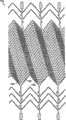
图3A-3F是用于图2A中系统的阻塞装置的各种实施例的平面图。虽然阻塞装置优选是管状结构,但是图3A-3F中每一副图的装置是打开的,如同被纵向切割并且展平成片以便可以更容易地观察其特征。3A-3F are plan views of various embodiments of an occlusion device for use in the system of FIG. 2A. While the blocking device is preferably a tubular structure, the device in each of Figures 3A-3F is opened as if cut lengthwise and flattened into pieces so that its features can be more easily viewed.
图4A和4B是图3A的阻塞装置的透视图。4A and 4B are perspective views of the occlusion device of FIG. 3A.
图5A是与图3A类似的另一替代性阻塞装置的平面图。Figure 5A is a plan view of another alternative occlusion device similar to Figure 3A.
图5B是图5A的阻塞装置的透视图。Figure 5B is a perspective view of the occlusion device of Figure 5A.
图6是与图3A类似的又一替代性阻塞装置的平面图。Figure 6 is a plan view of yet another alternative occlusion device similar to Figure 3A.
图7A是在装置被形状设定为螺旋形式前的与图3A类似的另一替代性阻塞装置的平面图。Figure 7A is a plan view of another alternative occlusion device similar to Figure 3A, before the device is shaped into a helical form.
图7B是与图7A类似的视图,其示出了已经被形状设定为包括右顺捻的装置。Figure 7B is a view similar to Figure 7A showing the device having been shaped to include clockwise lay.
图7C是与图7A类似的视图,其示出了已经被形状设定为包括左顺捻的装置。Figure 7C is a view similar to Figure 7A showing the device having been shaped to include left-hand lay.
图7D是图7B的装置的中心部分的透视图。Figure 7D is a perspective view of the central portion of the device of Figure 7B.
图8是与图3A类似的另一替代性阻塞装置的平面图。Figure 8 is a plan view of another alternative occlusion device similar to Figure 3A.
图9是与图3A类似的另一替代性阻塞装置的平面图。Figure 9 is a plan view of another alternative occlusion device similar to Figure 3A.
图10是与图3A类似的平面图,其示出了彼此交叠放置的图7B和7C中的装置。Figure 10 is a plan view similar to Figure 3A showing the devices of Figures 7B and 7C placed on top of each other.
图11是示出了图10的交叠装置的中心部分的透视图。FIG. 11 is a perspective view showing a central portion of the overlapping device of FIG. 10 .
图12A是与图3A类似的平面图,其示出了阻塞装置的另一实施例;所示装置位于可再次插入的方向内。Figure 12A is a plan view similar to Figure 3A showing another embodiment of an occlusion device; the device is shown in a reinsertable orientation.
图12B示出了位于不可再次插入的方向内的图12A中的装置。Figure 12B shows the device of Figure 12A in a non-reinsertable orientation.
图12C示出了一对被定位成交叠配置的图12A的装置,其中外部装置如图12B的方向定位且内部装置如图12A的方向定位。Figure 12C shows a pair of the devices of Figure 12A positioned in an overlapping configuration with the outer device oriented in the orientation of Figure 12B and the inner device oriented in the orientation of Figure 12A.
图13A-13E是示意性示出了血管内的动脉瘤并且示出了展开图1的动脉瘤阻塞系统的步骤序列的一系列图。13A-13E are a series of diagrams schematically illustrating an aneurysm within a blood vessel and illustrating a sequence of steps for deploying the aneurysm occlusion system of FIG. 1 .
图14是适用于分叉脉管的动脉瘤阻塞装置的一个替代性实施例的透视图。Figure 14 is a perspective view of an alternative embodiment of an aneurysm occlusion device suitable for use with a bifurcated vessel.
图15是图14的动脉瘤阻塞装置的侧视图。15 is a side view of the aneurysm occlusion device of FIG. 14 .
图16示意性示出了具有动脉瘤的分叉脉管,并且示出了在脉管内的图14中的动脉瘤阻塞装置。Figure 16 schematically illustrates a bifurcated vessel with an aneurysm, and shows the aneurysm blocking device of Figure 14 within the vessel.
图17A是示出了用于从管上切下图14中的动脉瘤阻塞装置的式样的平面图。虽然该式样一般是圆筒形的,但是为了简单,图17A将该式样表示为如同被纵向切割并且被展平。17A is a plan view showing a pattern for cutting the aneurysm blocking device of FIG. 14 from a tube. Although the pattern is generally cylindrical, for simplicity Figure 17A shows the pattern as if cut lengthwise and flattened.
图17B是示出了在将装置成形为最终形状的步骤之前符合使用图17A的式样进行切割以便形成图14的阻塞装置的管材的透视图。17B is a perspective view showing tubing cut to form the occluding device of FIG. 14 consistent with the pattern of FIG. 17A prior to the step of forming the device into its final shape.
图18A-18F是示出了植入图14中阻塞装置的顺序图。18A-18F are sequential views illustrating implantation of the occlusion device of FIG. 14 .
具体实施方式 Detailed ways
图2A示出了动脉瘤阻塞系统100的一个实施例。一般来讲,系统100包括阻塞装置10、护套12和推动器14。导引线16也可用于系统100。One embodiment of an
阻塞装置10是管状装置,该管状装置能够在展开之前被保持成受限形式或形状,然后在展开时扩张成接触脉管壁。用于套管的适当材料包括含超弹性镍钛诺或形状记忆聚合物的形状记忆材料或如不锈钢、复合材料或金属和聚合物材料的组合物的其他材料。在一个优选实施例中,可以通过在一定长度的超弹性镍钛诺管材上激光切割特征,然后使用本领域技术人员公知的方法对材料进行一次或多次化学处理和形状设定,从而形成阻塞装置10。如下面将更详细的讨论,装置10的壁被构造成限制从脉管进入到从该脉管突出的动脉瘤中的血液通道,而不会妨碍进入到可能会在动脉瘤区域存在的任意侧支脉管内的血液流动。The
阻塞装置10被配设成植入到脑脉管系统中,该脑脉管系统包括但不限于颈内动脉、颈外动脉、椎动脉、基底动脉、大脑中动脉、大脑前动脉和大脑后动脉。优选的装置10可被扩张至范围在2.0mm-6.0mm的外直径。使用者可以配备有一套具有不同直径的多阻塞装置,以便可以根据手术过程选择具有最合适尺寸的装置。The
护套12是细长管状导管,其优选地由例如Pebax(嵌段聚醚酰胺树脂)、尼龙、聚氨酯、PTFE(聚四氟乙烯)、聚酰亚胺的聚合物材料、例如不锈钢、铂等的金属或其他适当材料形成。中心内腔13沿护套12的长度延伸。护套被配设成通过脑脉管的通道,并且可以具有范围在1mm-2mm内的外直径。The
推动器14是具有内腔18的细长管状构件。推动器14的远端包括具有扩口段20和锥形段22的防损伤尖端。圆筒形肩部24位于推动器14的外部上、并且在接近扩口段20并与其分隔开的位置处。推动器可以由适合的聚合物、金属和/或复合材料形成。参见图2B,当系统100被组装以便展开阻塞装置10时,装置10被装到推动器14之外,此时装置10被径向压缩到其受限位置并且被定位成使其近端邻接推动器14外表面上的肩部24。护套12被放置在推动器和阻塞装置10之外以便将装置10维持在图2B所示的受限位置内。The
推动器14的远端可以包括钩(未示出)或等价机构,其可拆卸地接合装置10的近侧部分。当装备有钩时,如果在装置被部分展开后决定要使用更小或更大的装置时,或者如果装置需要被再次放置时,所述钩可以被用于将装置10拉回到护套12内。一旦装置被最终展开,所述钩可以从装置上拆下。用于再次插入和/或再次放置血管内装置的类似系统可见于血管内支架领域。The distal end of
阻塞装置10可以用许多方式来构造。参见图1,优选的阻塞装置包括实现如下效果的特征:当装置被放置在血管V内覆盖通向动脉瘤A的开口时,该装置可以阻塞进入动脉瘤的血液流动并且即使阻塞装置的位置覆盖了通向侧支脉管的开口也不会严重地阻住进入支脉管B的血液流动。这里描述了阻塞装置的几个实施例,其中每个实施例均包括这样的优选特征。然而,应该意识到,在不背离本发明范围的情况下,各种其他的实施例也是可能的。The blocking
公开的实施例仅依赖于动脉瘤的位置处的流体动力学以及侧支脉管处的流体动力学之间的差异。循环系统内的平均动脉压力和流动特性随着距心脏的距离、位置及脉管直径而变化。除了异常或生理性动脉-静脉分流的环境外,流动由正压力梯度从循环系统的动脉侧驱动到静脉侧。具体脉管构筑空间的不同隔室内的压力和流动是由这些因素确定的。一般而言,压力的范围在25-100mmHg范围内的平均动脉压力到不超过静脉侧的大约15mmHg之间。The disclosed embodiments rely solely on the difference between the fluid dynamics at the location of the aneurysm and the fluid dynamics at the side branch vessels. Mean arterial pressure and flow characteristics within the circulatory system vary with distance from the heart, location, and vessel diameter. Except in the setting of an abnormal or physiologic arteriovenous shunt, flow is driven by a positive pressure gradient from the arterial to the venous side of the circulatory system. The pressure and flow within the different compartments of a particular vascular architecture space are determined by these factors. In general, pressures range from mean arterial pressure in the range of 25-100 mmHg to about 15 mmHg not exceeding the venous side.
再次参见图1,在主脉管V内的流体动力学和压力与朝向毛细血管床的支脉管B内的流体动力学和压力不同,并且在主脉管V和支脉管B之间有压力梯度。然而,因为动脉瘤没有静脉流出,所以在主脉管V和动脉瘤A之间没有压力梯度。因此,在主脉管V的动脉瘤扩张A内存在漩涡(由箭头F指出)而不是存在于主脉管V和支脉管B内的层流流型L1、L2。Referring again to Figure 1, the fluid dynamics and pressures within the main vessel V are different from those in the branch vessel B towards the capillary bed, and there is a pressure gradient between the main vessel V and branch B . However, there is no pressure gradient between main vessel V and aneurysm A because there is no venous outflow from the aneurysm. Thus, there is a vortex (indicated by arrow F) within the aneurysmal dilation A of the main vessel V instead of the laminar flow pattern L1, L2 present in the main vessel V and branch vessels B.
优选的阻塞装置利用了这些差异从而阻塞了向动脉瘤的流动而不阻塞向侧支脉管的流动。这些装置包括具有多个间隙或小孔的阻塞侧壁。术语“侧壁”不严谨地被用于指代围绕内腔的结构,并且不意味着建议为不渗透性结构。阻塞侧壁是可被放置成覆盖动脉瘤的侧壁的高覆盖率部分。Preferred occlusion devices take advantage of these differences to occlude flow to the aneurysm without blocking flow to collateral vessels. These devices include an obstructed sidewall with a plurality of gaps or pores. The term "sidewall" is used loosely to refer to the structure surrounding the lumen and is not meant to suggest an impermeable structure. The occluded sidewall is a high coverage portion that can be placed to cover the sidewall of the aneurysm.
因为装置内间隙的尺度小,所以形成在装置上的新血管内膜(内皮细胞的新层)能够通过阻住一些或全部间隙从而有助于装置的阻塞特性。同样,由于间隙的尺寸小,所以在间隙内的血液的表面张力也可以增强装置的阻塞特性。当阻塞侧壁覆盖支脉管B时,在支脉管B和主脉管V内流动的血液的压差会使得血液流动通过主脉管和支脉管之间的侧壁。在一些情况下,这可能是因为压差导致了间隙周围材料(例如带(band))的偏移。例如,偏移可以是纵向的或径向的,并且可以是脉动的或者是恒定的。在一些实施例中,这个偏移可以导致间隙从阻塞尺寸扩展到足以使血液在支脉管B和主脉管V之间流动前进的尺寸。此外,脉动的偏移可以干扰跨过间隙的血液表面张力的均一性,并且/或者在其作用是使血液流动通过阻塞侧壁的间隙进入到支脉管中的任意情况中均可以防止在覆盖支脉管的装置的部分上形成新血管内膜。在其他情况下,压差本身(而不是围绕间隙的结构的运动)可以干扰血液表面张力和/或新血管内膜的形成,从而允许血液流动通过阻塞侧壁。Because of the small size of the gaps within the device, the neointima (a new layer of endothelial cells) that forms on the device can contribute to the occlusive properties of the device by blocking some or all of the gaps. Also, due to the small size of the gap, the surface tension of the blood within the gap can also enhance the occlusive properties of the device. When the blocked sidewall covers branch vessel B, the pressure difference of blood flowing in branch vessel B and main vessel V causes blood to flow through the sidewall between the main vessel and branch vessel. In some cases, this may be due to pressure differentials causing deflection of material (eg, bands) around the gap. For example, the offset can be longitudinal or radial, and can be pulsed or constant. In some embodiments, this offset may cause the gap to expand from an obstructive size to a size sufficient to allow blood flow between branch vessel B and main vessel V to progress. In addition, the offset of the pulsation can disturb the uniformity of the surface tension of the blood across the gap and/or can prevent the overlying of the branch vessel in any case where it acts to allow blood to flow through the gap blocking the sidewall into the branch vessel. Neovascular intima forms on parts of the tube device. In other cases, the pressure differential itself (rather than the movement of structures surrounding the gap) can interfere with blood surface tension and/or neointima formation, allowing blood flow through the sidewall of the blockage.
另一方面,因为在主脉管V和动脉瘤A之间没有明显的压降,所以由于缺少间隙的有效扩展并且/或者由于跨过间隙的血液表面张力并且/或者由于间隙内/上存在新血管内膜,侧壁的所述部分会阻塞动脉瘤。On the other hand, because there is no appreciable pressure drop between the main vessel V and the aneurysm A, due to lack of effective expansion of the gap and/or due to the surface tension of blood across the gap and/or due to the presence of new The intima, the part of the side wall that blocks the aneurysm.
在一个示出的实施例中,动态间隙表现为在形成装置侧壁的材料带之间的空间的形式。然而,应该意识到,在不背离本发明范围的情况下,其他机构也可以被用于产生这些动态间隙。例如,侧壁可以由带小孔的材料形成,这些小孔可以响应主脉管和侧脉管之间的压差而弹性地延展。In one illustrated embodiment, the dynamic gap takes the form of the space between the strips of material forming the side walls of the device. However, it should be appreciated that other mechanisms may be used to create these dynamic gaps without departing from the scope of the present invention. For example, the sidewall may be formed of a material with pores that elastically expand in response to a pressure differential between the main vessel and the side vessel.
此外,公开的实施例被配置成使得阻塞侧壁内的间隙的排列围绕阻塞侧壁的圆周在机能上一致。换言之,遍及动脉瘤的动态间隙的行为不取决于阻塞侧壁的哪个部分被放置在动脉瘤上或者阻塞侧壁的哪个部分覆盖支脉管。因此,这些实施例中,医师不需要试图沿阻塞侧壁的圆周用特定区(也被称为“高覆盖率区”)来覆盖动脉瘤。Furthermore, the disclosed embodiments are configured such that the arrangement of gaps within the blocking sidewall is functionally consistent around the circumference of the blocking sidewall. In other words, the behavior of the dynamic gap across the aneurysm does not depend on which portion of the occluded sidewall is placed on the aneurysm or which portion of the occluded sidewall covers the branch vessel. Thus, in these embodiments, the physician need not attempt to cover the aneurysm with a specific zone (also referred to as a "high coverage zone") along the circumference of the obstructed sidewall.
参考附图,同样的数字被用于指代不同实施例中彼此相似的特征。Referring to the drawings, like numerals are used to refer to mutually similar features in different embodiments.
图3A示出了阻塞装置10a的第一实施例。阻塞装置优选地是具有近侧部分26、中心部分28和远侧部分30的管状装置。优选地通过将特征激光切割到一段镍钛诺管材中来形成装置10a的特征。在使用中被置于覆盖动脉瘤的中心部分28被切割成具有被镍钛诺材料的区域33分隔开的多个间隙31的高覆盖率图案。如上所述,间隙31被排布成当中心部分的区域位于支脉管B上时(图1),从主脉管V进入支脉管B的流体流动将使间隙分开足以允许正常流体流动进入支脉管B的量。然而,因为在主脉管V和动脉瘤A之间存在最小压差,所以在位于动脉瘤A上的中心部分的区域内间隙不会明显地分开。这样,中心部分显著地减少了进入动脉瘤的血液流动。Figure 3A shows a first embodiment of a blocking device 10a. The occlusion device is preferably a tubular device having a
在图3A的实施例中,区域33采取限定了间隙31的多条波浪形箍带(cuff)、带或条带的形式。箍带内可能接近箍带和细长竖直件或直立件32(下面予以描述)之间的交叉点的弯曲或波浪有助于允许装置折叠成压缩或受限状态以便在输送护套12内的输送(图1)。In the embodiment of FIG. 3A ,
每条箍带33可以具有近似0.0005至0.0015英寸的宽度(即,在相对于装置10a的中心轴线的纵向方向内),并且间隙31的宽度(即,箍带33之间的纵向间隔)在0.002至0.020英寸的范围内。中心部分28的长度在6-30mm的范围内。Each
如图3A所示,细长竖直件或直立件32从近侧部分26延伸到远侧部分30。竖直件32为中心部分提供轴向强度并且有助于保持间隙31的理想间隔。如果如上所述在脉管内部分展开后需要重新定位装置时,竖直件也可以被用于为装置提供轴向力。As shown in FIG. 3A , an elongated vertical member or
在一个实施例中,可以使用2-8个竖直件。腿34a从多个竖直件32的近端延伸出,并且腿34b从多个竖直件32的远端延伸出。虽然在所示实施例中,腿34a和腿34b在交替的竖直件上,但是也可以使用其他配置。每个腿34a、34b均包括孔眼35a、35b。In one embodiment, 2-8 vertical members may be used. Legs 34a extend from proximal ends of the plurality of
在近侧部分26处,大体V形支柱构件36被连接在竖直件32之间,并且支柱构件的顶点38朝向中心部分28延伸。在远侧部分30处,大体V形支柱构件40被连接在竖直件32之间,并且支柱构件40的顶点42延伸远离中心部分28。支柱构件36、40有助于保持装置10a的圆筒形形状,并且也通过为装置提供折叠点而有利于装置的收缩以便将装置载入护套12中(图2A和2B)。为了折叠装置以便插入护套,丝线或金属丝穿过腿34b上的孔眼35b,并且第二丝线/金属丝穿过腿34a的孔眼35a。向丝线施加张力,因而朝图3A箭头指示的方向拉动腿34a、34b,从而使得装置沿支柱构件36、40的顶点折叠并且因此将装置置于径向压缩构型。At the
通过使用漏斗以便于将装置10a载入护套内,其中该漏斗的锥形端被插入到护套的远端内。为了将装置10a载入护套内,穿过在装置近端处的孔眼35a的丝线/金属丝被插入到漏斗的扩口端内并且通过护套直到其离开护套的近端为止。在装置的近端和远端向丝线施加张力,以便如前段所述折叠装置10a。被折叠的装置被拉动通过漏斗并且进入护套。通过使装置进入漏斗来辅助折叠步骤。Loading of the device 10a into the sheath is facilitated by the use of a funnel whose tapered end is inserted into the distal end of the sheath. To load the device 10a into the sheath, a wire/wire threaded through the
图3B示出了阻塞装置10b的第二实施例。在装置10b中,多条螺旋定向的带42形成了高覆盖率中心区域28b。带42优选地以小间距被隔开从而在区域28b内提供高覆盖率(例如,40-50%覆盖率)。带42的远端被连接到在装置的远侧区域30b处的八个相应的直立件32(但是如其他地方所述,装置也可以包括其他数量的直立件)。V形支柱40b在其腿处被连接到直立件32。带的近端被连接到在装置的近侧部分26b处的V形支柱36b的顶点。如图所示,波浪形箍带结构44与带42相交并且环绕所述装置。当装置被定位在脉管系统的转弯内或或经过所述转弯时,这些箍带结构44有助于防止装置展平。如上所述提供腿34a、34b以及孔眼35a、35b。Figure 3B shows a second embodiment of the blocking device 10b. In device 10b, a plurality of helically oriented strips 42 form a high coverage central region 28b. Bands 42 are preferably spaced at small intervals to provide high coverage (eg, 40-50% coverage) within region 28b. The distal end of the strap 42 is connected to eight
在如图3C所示的可替换装置10c中,装置10c不具有V形支柱36、40,而是包括在竖直件32a、32b之间延伸的圆周箍带构件46。箍带构件46包括在与竖直件32a的交叉点附近的朝向近端定向的弯曲48以及在与竖直件32b的交叉点附近的朝向远端定向的弯曲50。在图3A的实施例中,装置的高覆盖率中心部分28c由小间距的材料带33c形成。这些带33c在竖直件附近具有微小弯曲52、54,这使得带33c具有与箍带构件54相同或近似的形状。如下所述,这些弯曲形成了折叠点,装置沿这些折叠点折叠以便插入到护套12内(图2A)。In an
竖直件32a、32b可以包括例如S-弯曲60的屈曲部分以便增加挠性而不会显著地危害裂断强度(column strength)。如图3D所示,在竖直件32上的附加屈曲部分60a可以被定位在高覆盖率中心部分28d内的带33d的行之间以便提高装置的抗弯折性。在这个实施例中,带33d具有波浪形以便容纳屈曲部分60a。如所示,箍带46可以具有类似形状。The
再次参考图3C,以类似于上述的方式执行折叠装置10c并将其插入护套中的步骤。如箭头A1和A2所示,当竖直件32a朝近端方向被拉动的同时竖直件32b朝远端方向被拉动。当装置10c折叠时,箍带构件46在弯曲48、50处折叠。因为在本申请中公开的附加实施例使用类似过程被插入护套,所以在此实施例中不再重复这个过程。Referring again to Figure 3C, the steps of folding the
从图中显而易见的是,竖直件32可以具有不同构造。一些竖直件可以在装置的长度上延伸(例如图3C和3D),而另一些可以仅在装置的近侧部分或远侧部分处延伸(图3B)。在另一些实施例中,竖直件可以从装置的近端或远端开始延伸、通过高覆盖率中心部分并且之后终止在未到达装置相对端的位置处。可以使用任意数量的竖直件,不过优选地在2至8个竖直件之间。竖直件32a可以如图3C和3D所示是大体竖向的,或者装置可以使用如图3E所示的螺旋竖直件32e。在一些实施例中,可以包括附加孔眼35d,例如如图3D所示在相对于装置端部更靠近中心的竖直件的部分上包括所述附加孔眼。在载入装置的期间,丝线可以穿过这些孔眼并且用于压缩所述装置以便载入到展开护套中。这些孔眼(如此文中其他地方描述的其他孔眼)在其上也可以包括不透射线的标记材料以便在植入期间有助于荧光法定位所述装置。It is apparent from the figures that the
图3F示出了在中心区28f中提供非常高的覆盖率的装置的另一个实施例。这里,带33f被成形为具有窄缝58的宽带。Figure 3F shows another embodiment of a device that provides very high coverage in the
图5A和5B示出了阻塞装置10g的一个可替换实施例。图5A的实施例不同于图3A-3F的实施例,其中装置的高覆盖率中心部分28g由多个桨(paddle)33g形成。桨33g被竖直件32g支承,所述竖直件32g可以包括例如“S”形区域60g的蜿蜒的屈曲部分。这些桨可以由相同的管激光切割而成,或者使用例如PTFE或其他聚合物的不同材料形成并且附连到竖直件32g。Figures 5A and 5B show an alternative embodiment of a blocking device 1Og. The embodiment of Figure 5A differs from that of Figures 3A-3F in that the high coverage
装置10g被构造为当一些桨33g被定位在支脉管之上时,通过从主脉管到支脉管的流体压力可以使那些桨向外偏转,从而允许进入支脉管内的正常流动继续流动。然而由于缺乏在主脉管和支脉管之间的压差,所以位于动脉瘤之上的那些桨33g具有零偏转度到有限的偏转度,因而防止了血液流入动脉瘤。The
在图6中对于图5A实施例的修改中,阻塞装置10h可以包括以更高密度排布的桨33h。这些桨可以被从竖直件32h延伸出的横向支柱64支承。如所示,结合图5A实施例的描述,支柱可以包括具有“S ”图案的屈曲部分从而允许桨的偏转。桨33h可以包括穿孔66,或者可以为了最大覆盖率而不具有穿孔(见桨33h′)。In a modification of the embodiment of FIG. 5A in FIG. 6, the blocking means 10h may comprise
图6实施例图示了如果需要,为了结构刚度或为了有助于将装置载入到护套12(图2A)内,装置可以包括附加支承特征。例如,多行支柱构件62可以在竖直件32h之间延伸。替代性地或者除支柱构件62以外,圆周箍带68可以在竖直件32h之间延伸。竖直件32h可以包括S-弯曲52的屈曲部分60h以便增加挠性而不会显著地危害裂断强度。The FIG. 6 embodiment illustrates that the device may include additional support features, if desired, for structural rigidity or to facilitate loading of the device into the sheath 12 ( FIG. 2A ). For example, rows of
图7A-7D示出了植入物的另一个实施例10i。参考图7A,装置10i包括被多个V形带或连接件70连接到一起的三个直立件32i。这个排布以及本文中所述的许多其他排布是有利的,因为采用所述排布的装置当其在脉管内展开而从其径向压缩位置延伸时,其在长度上不会显著地变短。在植入期间,医师首先将装置(被压缩在护套12内)邻近动脉瘤颈A定位,然后从护套中释放该装置。术语“缩短量(foreshortening)”是本领域公知的,其指代装置从在导管内采用的长度缩短到当该装置张开到推荐与最大脉管的壁接触时所采用的长度的量。显著的缩短量为医师带来了挑战,因为这会导致当处于展开护套内与动脉瘤对齐的装置在从护套中释放时变短而不与动脉瘤对齐。本设计将缩短量限制在不超过15%,并且优选地不超过10%。Figures 7A-7D illustrate another embodiment of an implant 1Oi. Referring to FIG. 7A , device 10 i includes three uprights 32 i connected together by a plurality of V-shaped straps or
在高覆盖率区内,这些V形连接件70具有近似0.0005英寸-0.0012英寸的宽度(即,在垂直于连接件的长边的方向内)。V形连接件70之间的间隙在垂直于V形连接件70的长边的方向内具有近似0.005-0.015英寸的宽度。在近段和远段内,V形连接件可以具有在0.0008英寸-0.0016英寸范围内的宽度。In the high coverage area, these V-shaped
如所示,V形连接件在高覆盖率区28i内以小间距隔开,并且在近段和远段26i、30i内以更小间距隔开。V形连接件的顶点指向同一方向以便协助将装置载入到展开护套内,并且允许当在展开期间需要重新定位装置时将装置拉入护套。可设置装置的近段26i包括附加长度(与远段长度相比),以便允许如果需要的话在展开期间重新插入装置。因此,装置10i可以被配置成具有长度为2-15mm(优选地3-7mm)的近段26i、长度为近似2-40mm(优选地在10-14mm的范围内)的高覆盖率段28i以及长度为2-15mm(优选地3-5mm)的远段30i。当完全张开时,装置的外直径近似1-10mm,并且优选地3.5-5.5mm。As shown, the V-shaped connectors are spaced at small intervals within the high-
在一个构型中,装置10i是用镍钛诺管激光切割而成,并且之后被扭曲并且被形状设置成螺旋形地定位直立件32i。已经发现,螺旋排布有助于展开的装置符合脉管壁,并且也可以改进装置的抗弯折能力。图7B图示在使用右顺捻形状设定后装置呈现为被纵向切割并且展平。图7C是在使用左顺捻形状设定后装置所呈现的类似视图。图7D是图7B装置的高覆盖率段28i在形状设定后的透视图。如图7B和7C所示,不透射线的标记72被定位在稍远于和稍近于高覆盖率段28i处的孔眼35a、35b和V-连接件70上。In one configuration, the device 1Oi is laser cut from a nitinol tube and then twisted and shaped to helically position the uprights 32i. It has been found that the helical arrangement helps the deployed device conform to the vessel wall and may also improve the buckling resistance of the device. Figure 7B illustrates the device appearing to be cut lengthwise and flattened after shape setting using a right-hand twist. Figure 7C is a similar view of what the device would look like after using left-hand lay shape setting. Figure 7D is a perspective view of the
在一些情况下,将装置10i形状设定为螺旋可以导致在装置的高覆盖率区28i内形成间隙。具体地,对于任意一个给定的V形连接件70,使装置形成为螺旋将使“V”的一个腿移位到更接近相邻V形连接件的相应腿处并且同时会扩大“V”的另一个腿和相邻V形连接件的相应腿之间的间隙。这可以增加进入动脉瘤的血液流动,因为这会降低覆盖动脉瘤的一些区域的金属百分比,同时增加其他区域之上的覆盖百分比。图8所示的装置10j被设计成在装置被形状设定成螺旋后在V形连接件70j之间的间隙宽度会变得一致。更具体地,图8实施例通过切割每一个包括一个窄腿74a和一个宽腿74b的“V”而被制造,从而最初腿74a之间的间隙大于相邻连接件70j上的腿74b之间的间隙。当装置被形状设定时,V形连接件70j的形状的改变会导致腿74a之间的间距和腿74b之间的间距大约相等。在图9所示的改进装置10k中,通过直接将镍钛诺管切割成螺旋形状而形成装置10k,并且每个V形连接件70k的一个腿74b具有大于相对腿74a的宽度。在这个实施例中,形状设定步骤可以被省略,或者可以执行形状设定以便增加螺旋的螺旋角。In some cases, shaping the device 1Oi as a helix may result in the formation of gaps within the
当需要进一步增加覆盖百分比并且减少提供在动脉瘤之上的孔尺寸时,一对装置可以被定位在脉管内,其中一个装置被同轴放置在另一个装置内。根据一个实施例,具有如图7A所示的左顺螺旋捻的第一装置被定位在脉管内、跨过动脉瘤,并且具有如图7B所述的右顺螺旋捻的第二装置被定位在第一装置内,优选地高覆盖率中心区域直接彼此重叠。所述装置的排布(如果被纵向切割并展平)如图10所示,其中一个装置被标为D1并且另一个被标为D2。在这个实施例中,用于形成内装置和外装置的扭转角近似是20-40度。When it is desired to further increase the coverage percentage and reduce the size of the hole provided over the aneurysm, a pair of devices can be positioned within the vessel, with one device placed coaxially within the other device. According to one embodiment, a first device with a left-handed helical twist as shown in FIG. 7A is positioned within the vessel across the aneurysm, and a second device with a right-handed helical twist as described in FIG. 7B is positioned at Within the first arrangement, preferably the high coverage central regions directly overlap each other. The arrangement of the devices (if cut lengthwise and flattened) is shown in Figure 10, with one device labeled Dl and the other labeled D2. In this embodiment, the twist angle used to form the inner and outer devices is approximately 20-40 degrees.
图11示出了嵌套装置的高覆盖率段281的透视图。可以看出,两个装置的组合在高覆盖率区281上产生了网,因而增加了覆盖动脉瘤颈的金属的百分比(并且减少了在动脉瘤颈处的装置内的孔尺寸)。例如,以图7A-7D所示的装置类型作为示例,为了示例的目的,假设所述装置的V-连接件之间的间隙的宽度近似0.015英寸、长度近似0.110英寸,用具有相反的螺旋形状的相同装置重叠所述装置,从而可以定位这两个装置的V-连接件以相交产生重叠装置的组合的孔尺寸/间隙尺寸,该尺寸为0.015英寸×0.015英寸的正方形而不是单一装置的0.015英寸×0.110英寸的长方形。Figure 11 shows a perspective view of the
如图10所示,在装置的孔眼端上的不透射线的标记721以及在高覆盖率段281的边界处的类似标记允许使用者在荧光镜显影下准确对齐所述装置。在公开的实施例中,装置仅需要被纵向对齐而不需要轴线对齐,因而避免了在植入期间扭转展开护套和相关工具的需要。如图10或11所示可以是完全的纵向对齐,或者可以是部分的纵向对齐。As shown in Figure 10,
非螺旋装置可以替代性地以重叠排布的方式展开。图12A示出了可被用于此目的的装置10m的一个实施例。如图7A-7C的实施例,图12A实施例包括在直立件32m之间延伸的V形连接件70m。在近端76上,在V形连接件的顶点处添加一对附加直立件32m′。在图示的顶部示出的远端78上,添加了附加孔眼。这些额外特征增强了装置在展开期间的推进性。如前述设计,屈曲部分60m被定位在直立件32m上从而允许所述装置在经过曲折脉管系统时弯曲。Non-helical devices may alternatively be deployed in an overlapping arrangement. Figure 12A shows one embodiment of a device 10m that may be used for this purpose. As with the embodiment of Figures 7A-7C, the Figure 12A embodiment includes V-shaped connectors 70m extending between uprights 32m. On the
在一种展开图12A实施例的方法中,使用了两个相同装置。第一装置被定位在脉管系统内,且其高覆盖率区域28m被定位在动脉瘤颈之上,然后相同的第二装置被定位在第一装置内,且其高覆盖率区域与第一装置的高覆盖率区域重叠。例如,第一装置可以被定位成端部76如图12B所示朝远端方向定向,第二装置可以被定位成端部78如图12A所示朝远端方向定向。对于第二(内部)装置的这个定向是有利的,因为该定向使V-连接件70m定位成顶点指向远离展开护套处,这样当展开期间需要重新定位时允许内部装置被再次插入。然而,装置也可以被定位成第一(外部)装置在可再次插入的取向(图12A所示的取向)内,并且第二(内部)装置在如图12B所示的取向内。In one method of deploying the embodiment of Figure 12A, two identical devices are used. A first device is positioned within the vasculature with its high-
如图12C的放大段所示,通过将第一和第二装置的V-连接件70m定向在相反方向内,网型排布80被形成在高覆盖率区28m内。As shown in the enlarged section of Figure 12C, by orienting the V-connectors 70m of the first and second devices in opposite directions, a mesh arrangement 80 is formed within the
结合图13A-13E描述系统的展开和使用。该描述是在如下情形中给出的:动脉瘤A位于非常接近支脉管B处(同样参见图1)。在动脉瘤内的血液的涡流由箭头F代表。在主脉管和支脉管内的血液的层流相应地由箭头L1和L2代表。Deployment and use of the system is described in conjunction with Figures 13A-13E. This description is given in the context of an aneurysm A located very close to a branch vessel B (see also Fig. 1). The eddies of blood within the aneurysm are represented by arrows F. The laminar flow of blood in the main and branch vessels is represented by arrows L1 and L2 respectively.
在使用前,如结合图2B的描述,装置10、护套12和推动器14被组装。护套12将装置10维持在图2B所示的受限位置内。Prior to use,
参考图13A,在荧光镜显影下导引线16被引入到脉管系统内并且前进超过动脉瘤A。推动器14(其上有装置10和护套12)在导引线之上前进直到装置的远侧部分30位于超过动脉瘤A的位置并且装置10的中心部分28位于邻近动脉瘤的位置。之后护套12如图13B所示缩回,从而导致远侧部分30自动张开成在超过动脉瘤处接触脉管V的壁。在护套12的收回期间,保持抵靠推动器14的近端的压力以便护套的肩部24将装置保持在目标展开部位。Referring to FIG. 13A , a
护套12的继续收回导致装置10的中心部分28在邻近动脉瘤处被展开(图13C)。一旦装置10被展开,护套、推动器和导引线被从体内缩回。如图13D所示,装置10的存在减小了进入动脉瘤的血液流动,从而导致动脉瘤内的涡流F逐渐停止。如图13E所表示的,动脉瘤A最终凝结、结疤并且愈合。如上所述,通过支脉管B的层流L2继续流动并且不因装置10的存在而相对受到阻碍。Continued retraction of the
系统100(图2A)优选地包括用于阐述阻塞装置的展开步骤的使用说明以及根据需要包括用于再插入和/或再定位装置的使用说明。System 100 (FIG. 2A) preferably includes instructions for explaining the deployment steps of the occlusion device and, if desired, for reinserting and/or repositioning the device.
上述装置特别适用于在位于沿单一血管处的动脉瘤颈处提供阻塞。然而,有时,动脉瘤会出现在分叉点处的脉管分叉处。图14和15示出了一种动脉瘤阻塞装置,该阻塞装置使用单一装置阻塞了这种类型的动脉瘤,同时维持了通过主脉管分叉的未扰动的血液流动。该装置被设计成当在分叉脉管内展开时,该装置的高覆盖率部分会被定位在动脉瘤颈处以便最佳的阻塞。The device described above is particularly useful for providing occlusion at the neck of an aneurysm located along a single vessel. Sometimes, however, an aneurysm develops at a bifurcation of a vessel at a bifurcation point. Figures 14 and 15 illustrate an aneurysm occlusion device that occludes this type of aneurysm using a single device while maintaining undisturbed blood flow through the main vessel bifurcation. The device is designed so that when deployed within a bifurcated vessel, the high coverage portion of the device will be positioned at the neck of the aneurysm for optimal occlusion.
参考图15,阻塞装置110是具有远侧茎杆部分120和一对近侧分支130a、130b的大体Y形装置。一对V-构件140在近侧分支130a、130b之间延伸。V-构件140在其顶点处可折叠以便允许近侧分支130a、130b彼此靠近从而在植入之前将装置定位在展开导管内。一旦从导管中释放,V-构件140返回图14和15所示位置,从而回复装置110的Y形,这样每一个分支130a、130b和茎杆部分120可以被放置在分叉的独立分支内(图16)。V-构件朝向相应脉管的壁轻压分支130a、130b,从而将装置锚定在适当位置。Referring to Figure 15, the
在一种制造方法中,装置110从镍钛诺合金管材激光切割而成。图17A示出了图案的展平图,管材可以以该图案被切割形成所述装置。图案被以展平状态示出从而清楚地示出细节。因此,即使分支130a是沿圆筒形管材切割而成的单一部件,但是分支130a被图示成在视图左手侧和右手侧上的两片。In one method of fabrication,
装置110包括一对从远端开始延伸的直立件150。如前述实施例所述,直立件可以包括孔眼152和屈曲部分154。V形连接件156在直立件之间延伸。附加孔眼152a可以被连接到在装置远端处的连接件156的顶点。
朝向装置的近端,V形连接件156的圆周长度减小以在分支130a、130b之间产生间隔158。每一个直立件150形成具有腿160的叉,所述腿160作为间隔158的边界。如所示,V-构件140被连接到腿160并且被定向成使其顶点在间隔158内。孔眼152b被定位在腿160的近端上。Towards the proximal end of the device, the circumferential length of the V-shaped
在一种生产所述装置的方法中,根据这个图案或类似图案切割管材,然后该管材被形状设定为将分支130a、130b分开到图14-16所示的位置。In one method of producing the device, the tubing is cut according to this or a similar pattern, and the tubing is then shaped to separate the
在一个实施例中,装置由具有近似为0.001英寸至0.007英寸壁厚的镍钛诺管形成,直立件的宽度在0.001英寸至0.007英寸的范围内,形成装置的高覆盖率区的V形连接件156的宽度为0.0005英寸-0.002英寸,并且V-构件140的宽度近似0.001英寸-0.005英寸。仅通过示例的方式给出这些尺寸,因为装置可以根据大量的不同尺寸制成。在上述的另一个实施例中,装置110(图15)优选地包括不透射线的标记从而允许在荧光镜显影下的植入。In one embodiment, the device is formed from nitinol tubing having a wall thickness of approximately 0.001 inches to 0.007 inches, with upstanding members having a width in the range of 0.001 inches to 0.007 inches, forming a V-shaped junction of the high coverage area of the device The width of
图18A-18F图示了可以被用于在动脉瘤上展开装置110的一个展开序列,其中该动脉瘤位于包括脉管分支V1、V2和V3的分叉处。如所示,装置110被定位在运送导管162上。远侧部分120被远侧护套164压缩。延伸通过远侧部分120的心轴165被连接到护套164的远端。分叉的近侧分支130a、130b被限制在近侧护套166内。18A-18F illustrate one deployment sequence that may be used to deploy
当装置的远侧部分120在脉管V2内时,向近端拉动近侧护套166(图18B),从而使装置的近侧分支130a、130b被释放并且张开到其打开的形状设定位置(图18C)。使用前后运动操纵导管从而将一个近侧分支130a定位成桥接动脉瘤A的颈并朝向脉管V3延伸,并且将另一个分支定位在脉管V1内。使用心轴165向远端推动远侧护套164(图18D)从而释放装置110的远侧部分120(图18E)。远侧护套164缩回通过装置的内腔,并且从身体上移除运送系统。虽然结合分叉的装置描述了这种展开方法,但是这种展开方法也可以被用于展开任意其他的公开装置,或者以远端优先方式展开动脉瘤阻塞领域之外的任意其他装置(例如,支架)。When the
在不超出本发明范围的情况下,本申请中描述的任意特征可以以各种方式彼此结合并且可以和其他特征结合。Any of the features described in this application may be combined in various ways with each other and with other features without exceeding the scope of the present invention.
应当意识到,结合前述描述,对于本领域普通技术人员而言,上面限定的实施例的大量变型是显而易见的。因此,本文示出并描述的本发明的那些具体实施例和方法并不限制本发明。更合适地,本发明的范围由权利要求及其等同物所限定。It should be appreciated that numerous variations of the above defined embodiments will be apparent to those of ordinary skill in the art in view of the foregoing description. Therefore, those specific embodiments and methods of the invention shown and described herein do not limit the invention. Rather, the scope of the invention is defined by the claims and their equivalents.
Claims (24)
Applications Claiming Priority (3)
| Application Number | Priority Date | Filing Date | Title |
|---|---|---|---|
| US79016006P | 2006-04-07 | 2006-04-07 | |
| US60/790,160 | 2006-04-07 | ||
| PCT/US2007/008655 WO2007117645A2 (en) | 2006-04-07 | 2007-04-06 | Aneurysm occlusion system and method |
Publications (2)
| Publication Number | Publication Date |
|---|---|
| CN101415380A CN101415380A (en) | 2009-04-22 |
| CN101415380B true CN101415380B (en) | 2012-06-20 |
Family
ID=38537931
Family Applications (1)
| Application Number | Title | Priority Date | Filing Date |
|---|---|---|---|
| CN2007800124835A Active CN101415380B (en) | 2006-04-07 | 2007-04-06 | Aneurysm occlusion device |
Country Status (5)
| Country | Link |
|---|---|
| US (1) | US20070239261A1 (en) |
| EP (1) | EP2004101A2 (en) |
| JP (1) | JP5061181B2 (en) |
| CN (1) | CN101415380B (en) |
| WO (1) | WO2007117645A2 (en) |
Families Citing this family (129)
| Publication number | Priority date | Publication date | Assignee | Title |
|---|---|---|---|---|
| US20030100945A1 (en) | 2001-11-23 | 2003-05-29 | Mindguard Ltd. | Implantable intraluminal device and method of using same in treating aneurysms |
| US6866679B2 (en) | 2002-03-12 | 2005-03-15 | Ev3 Inc. | Everting stent and stent delivery system |
| US8628564B2 (en) | 2004-05-25 | 2014-01-14 | Covidien Lp | Methods and apparatus for luminal stenting |
| US20060206200A1 (en) | 2004-05-25 | 2006-09-14 | Chestnut Medical Technologies, Inc. | Flexible vascular occluding device |
| US8398701B2 (en) | 2004-05-25 | 2013-03-19 | Covidien Lp | Flexible vascular occluding device |
| EP2419048A4 (en) | 2004-05-25 | 2014-04-09 | Covidien Lp | Vascular stenting for aneurysms |
| US9675476B2 (en) | 2004-05-25 | 2017-06-13 | Covidien Lp | Vascular stenting for aneurysms |
| US8267985B2 (en) | 2005-05-25 | 2012-09-18 | Tyco Healthcare Group Lp | System and method for delivering and deploying an occluding device within a vessel |
| US8617234B2 (en) | 2004-05-25 | 2013-12-31 | Covidien Lp | Flexible vascular occluding device |
| US9655633B2 (en) * | 2004-09-10 | 2017-05-23 | Penumbra, Inc. | System and method for treating ischemic stroke |
| WO2006127005A1 (en) | 2005-05-25 | 2006-11-30 | Chestnut Medical Technologies, Inc. | System and method for delivering and deploying and occluding device within a vessel |
| US8273101B2 (en) | 2005-05-25 | 2012-09-25 | Tyco Healthcare Group Lp | System and method for delivering and deploying an occluding device within a vessel |
| EP3127508A1 (en) * | 2006-02-14 | 2017-02-08 | Angiomed GmbH & Co. Medizintechnik KG | Highly flexible stent |
| US8152833B2 (en) | 2006-02-22 | 2012-04-10 | Tyco Healthcare Group Lp | Embolic protection systems having radiopaque filter mesh |
| US9615832B2 (en) | 2006-04-07 | 2017-04-11 | Penumbra, Inc. | Aneurysm occlusion system and method |
| US20120150147A1 (en) * | 2010-12-08 | 2012-06-14 | Penumbra, Inc. | System and method for treating ischemic stroke |
| EP2056747A2 (en) * | 2006-08-17 | 2009-05-13 | NFOCUS Neuromedical Inc. | Isolation devices for the treatment of aneurysms |
| JP5571566B2 (en) * | 2007-12-11 | 2014-08-13 | コーネル ユニヴァーシティー | Method and apparatus for sealing an opening in a side wall of a body lumen |
| US8968382B2 (en) | 2007-12-11 | 2015-03-03 | Cornell University | Method and apparatus for restricting flow through an opening in the side wall |
| US8157853B2 (en) * | 2008-01-24 | 2012-04-17 | Medtronic, Inc. | Delivery systems and methods of implantation for prosthetic heart valves |
| DE102008010507B3 (en) * | 2008-02-22 | 2009-08-20 | Acandis Gmbh & Co. Kg | Stent and method of making such a stent |
| CA2722037C (en) | 2008-04-21 | 2016-03-22 | Nfocus Neuromedical, Inc. | Braid-ball embolic devices and delivery systems |
| JP2011519300A (en) | 2008-05-01 | 2011-07-07 | アニュクローズ エルエルシー | Aneurysm occlusion device |
| US10716573B2 (en) | 2008-05-01 | 2020-07-21 | Aneuclose | Janjua aneurysm net with a resilient neck-bridging portion for occluding a cerebral aneurysm |
| US10028747B2 (en) | 2008-05-01 | 2018-07-24 | Aneuclose Llc | Coils with a series of proximally-and-distally-connected loops for occluding a cerebral aneurysm |
| US9675482B2 (en) | 2008-05-13 | 2017-06-13 | Covidien Lp | Braid implant delivery systems |
| US9179918B2 (en) | 2008-07-22 | 2015-11-10 | Covidien Lp | Vascular remodeling device |
| WO2010085344A1 (en) | 2009-01-22 | 2010-07-29 | Cornell University | Method and apparatus for restricting flow through the wall of a lumen |
| DE102009010824B4 (en) | 2009-02-26 | 2017-08-17 | Acandis Gmbh & Co. Kg | Medical implant, method for its production and method for introducing a medical implant into a delivery system |
| WO2010147807A1 (en) * | 2009-06-15 | 2010-12-23 | Boston Scientific Scimed, Inc. | Multi-layer stent assembly |
| US8409269B2 (en) | 2009-12-21 | 2013-04-02 | Covidien Lp | Procedures for vascular occlusion |
| JP2013509912A (en) * | 2009-11-03 | 2013-03-21 | ラージ ボア クロージャー, エル.エル.シー. | Closure device |
| ES2534192T3 (en) | 2009-11-09 | 2015-04-20 | Covidien Lp | Features of mesh ball embolic device |
| US9358140B1 (en) | 2009-11-18 | 2016-06-07 | Aneuclose Llc | Stent with outer member to embolize an aneurysm |
| DE102009060228B4 (en) * | 2009-12-23 | 2014-12-04 | Acandis Gmbh & Co. Kg | Medical devices |
| US8906057B2 (en) | 2010-01-04 | 2014-12-09 | Aneuclose Llc | Aneurysm embolization by rotational accumulation of mass |
| CN102770091B (en) | 2010-01-28 | 2015-07-08 | 泰科保健集团有限合伙公司 | Vascular remodeling device |
| CN102740799A (en) | 2010-01-28 | 2012-10-17 | 泰科保健集团有限合伙公司 | Vascular remodeling device |
| CN102711675A (en) * | 2010-03-23 | 2012-10-03 | 泰尔茂株式会社 | Repair material for conduit of living body |
| WO2011130256A2 (en) | 2010-04-13 | 2011-10-20 | Lumen Biomedical, Inc. | Embolectomy devices and methods for treatment of acute ischemic stroke condition |
| US8425548B2 (en) | 2010-07-01 | 2013-04-23 | Aneaclose LLC | Occluding member expansion and then stent expansion for aneurysm treatment |
| CN102451051B (en) * | 2010-11-03 | 2015-04-08 | 上海市第六人民医院 | Self-expandable segment tectorial asymmetric areolate stent |
| JP5868432B2 (en) | 2011-02-11 | 2016-02-24 | コヴィディエン リミテッド パートナーシップ | Two-stage deployed aneurysm embolization device |
| US20120239128A1 (en) * | 2011-03-16 | 2012-09-20 | Boston Scientific Scimed, Inc. | Stent and delivery system |
| US20120245674A1 (en) | 2011-03-25 | 2012-09-27 | Tyco Healthcare Group Lp | Vascular remodeling device |
| JP5770507B2 (en) * | 2011-03-28 | 2015-08-26 | テルモ株式会社 | Self-expanding stent and stent delivery system |
| US20130204288A1 (en) * | 2011-03-31 | 2013-08-08 | DePuy Synthes Products, LLC | Modifiable occlusion device |
| US20120253377A1 (en) * | 2011-03-31 | 2012-10-04 | Codman & Shurtleff, Inc. | Modifiable occlusion device |
| WO2012135859A2 (en) | 2011-04-01 | 2012-10-04 | Cornell University | Method and apparatus for restricting flow through an opening in the side wall of a body lumen, and/or for reinforcing a weakness in the side wall of a body lumen, while still maintaining substantially normal flow through the body lumen |
| AU2012248068B2 (en) * | 2011-04-29 | 2017-02-23 | Evasc Neurovascular Enterprises Ulc | Endovascular prosthesis and delivery device |
| US9138232B2 (en) | 2011-05-24 | 2015-09-22 | Aneuclose Llc | Aneurysm occlusion by rotational dispensation of mass |
| WO2012167156A1 (en) * | 2011-06-03 | 2012-12-06 | Pulsar Vascular, Inc. | Aneurysm devices with additional anchoring mechanisms and associated systems and methods |
| US10779855B2 (en) | 2011-08-05 | 2020-09-22 | Route 92 Medical, Inc. | Methods and systems for treatment of acute ischemic stroke |
| GB2494632A (en) | 2011-09-09 | 2013-03-20 | Isis Innovation | Stent and method of inserting a stent into a delivery catheter |
| US9060886B2 (en) | 2011-09-29 | 2015-06-23 | Covidien Lp | Vascular remodeling device |
| US12096951B2 (en) | 2011-10-05 | 2024-09-24 | Penumbra, Inc. | System and method for treating ischemic stroke |
| US20130226278A1 (en) | 2012-02-23 | 2013-08-29 | Tyco Healthcare Group Lp | Methods and apparatus for luminal stenting |
| US9072624B2 (en) | 2012-02-23 | 2015-07-07 | Covidien Lp | Luminal stenting |
| US9078659B2 (en) | 2012-04-23 | 2015-07-14 | Covidien Lp | Delivery system with hooks for resheathability |
| JP2015523121A (en) * | 2012-06-04 | 2015-08-13 | ピナンブラ、インク | Aneurysm occlusion system and method |
| US9155647B2 (en) | 2012-07-18 | 2015-10-13 | Covidien Lp | Methods and apparatus for luminal stenting |
| US9724222B2 (en) | 2012-07-20 | 2017-08-08 | Covidien Lp | Resheathable stent delivery system |
| RU2521833C2 (en) | 2012-10-18 | 2014-07-10 | Заза Александрович Кавтеладзе | Device for measuring pressure and introduction of medications into blood vessel aneurysm |
| US9301831B2 (en) | 2012-10-30 | 2016-04-05 | Covidien Lp | Methods for attaining a predetermined porosity of a vascular device |
| US9452070B2 (en) | 2012-10-31 | 2016-09-27 | Covidien Lp | Methods and systems for increasing a density of a region of a vascular device |
| CN104955420B (en) | 2012-10-31 | 2018-02-23 | 艾维斯科神经血管有限合伙公司 | Endovascular prosthesis |
| US9314248B2 (en) | 2012-11-06 | 2016-04-19 | Covidien Lp | Multi-pivot thrombectomy device |
| US9943427B2 (en) | 2012-11-06 | 2018-04-17 | Covidien Lp | Shaped occluding devices and methods of using the same |
| US20140180377A1 (en) * | 2012-12-20 | 2014-06-26 | Penumbra, Inc. | Aneurysm occlusion system and method |
| US10219924B2 (en) | 2012-12-26 | 2019-03-05 | Stryker Corporation | Multilayer stent |
| US9295571B2 (en) | 2013-01-17 | 2016-03-29 | Covidien Lp | Methods and apparatus for luminal stenting |
| US9157174B2 (en) | 2013-02-05 | 2015-10-13 | Covidien Lp | Vascular device for aneurysm treatment and providing blood flow into a perforator vessel |
| CN105163692B (en) * | 2013-02-28 | 2017-09-15 | 波士顿科学国际有限公司 | Implantable medical device that reduces tissue inflammation |
| IN2014DE00464A (en) | 2013-03-12 | 2015-06-12 | Depuy Synthes Products Llc | |
| IN2014DE00518A (en) | 2013-03-13 | 2015-06-12 | Depuy Synthes Products Llc | |
| US9463105B2 (en) | 2013-03-14 | 2016-10-11 | Covidien Lp | Methods and apparatus for luminal stenting |
| JP2016512751A (en) * | 2013-03-14 | 2016-05-09 | パルマズ サイエンティフィック, インコーポレイテッドPalmaz Scientific, Inc. | Integrated medical device, method for manufacturing the same, and method for using the same |
| AU2014237360B2 (en) | 2013-03-15 | 2018-07-26 | Insera Therapeutics, Inc. | Vascular treatment devices and methods |
| CN108433769B (en) | 2013-03-15 | 2021-06-08 | 柯惠有限合伙公司 | Occlusion device |
| US9907684B2 (en) | 2013-05-08 | 2018-03-06 | Aneuclose Llc | Method of radially-asymmetric stent expansion |
| CN103271780A (en) * | 2013-05-29 | 2013-09-04 | 郭伟 | Stent-graft blood vessel for treating aortic dissection |
| US10130500B2 (en) | 2013-07-25 | 2018-11-20 | Covidien Lp | Methods and apparatus for luminal stenting |
| WO2017142874A2 (en) | 2016-02-16 | 2017-08-24 | Insera Therapeutics, Inc. | Aspiration devices and anchored flow diverting devices |
| US9782186B2 (en) | 2013-08-27 | 2017-10-10 | Covidien Lp | Vascular intervention system |
| US10265207B2 (en) | 2013-08-27 | 2019-04-23 | Covidien Lp | Delivery of medical devices |
| US9265512B2 (en) | 2013-12-23 | 2016-02-23 | Silk Road Medical, Inc. | Transcarotid neurovascular catheter |
| US11547446B2 (en) | 2014-01-13 | 2023-01-10 | Trice Medical, Inc. | Fully integrated, disposable tissue visualization device |
| USD888245S1 (en) | 2014-03-14 | 2020-06-23 | Vactronix Scientific, Llc | Stent device |
| WO2016118669A1 (en) | 2015-01-20 | 2016-07-28 | Nsvascular, Inc. | Self-expandable scaffolding device for the treatment of aneurysms |
| CN105982712B (en) * | 2015-01-28 | 2018-01-30 | 上海交通大学 | Blood flow guider and its implementation |
| US11065019B1 (en) | 2015-02-04 | 2021-07-20 | Route 92 Medical, Inc. | Aspiration catheter systems and methods of use |
| JP6546761B2 (en) | 2015-03-18 | 2019-07-17 | 株式会社グッドマン | Stent |
| CN104758086B (en) * | 2015-04-20 | 2016-08-17 | 湖南埃普特医疗器械有限公司 | Cerebral aneurysm endoluminal vascular reconstructing device |
| CN104758023B (en) * | 2015-04-21 | 2017-07-18 | 仇汉诚 | A kind of blood flow turning rack |
| WO2017019563A1 (en) | 2015-07-24 | 2017-02-02 | Route 92 Medical, Inc. | Anchoring delivery system and methods |
| WO2017040681A1 (en) | 2015-09-01 | 2017-03-09 | Mivi Neuroscience, Inc. | Thrombectomy devices and treatment of acute ischemic stroke with thrombus engagement |
| US10314593B2 (en) | 2015-09-23 | 2019-06-11 | Covidien Lp | Occlusive devices |
| US10478194B2 (en) | 2015-09-23 | 2019-11-19 | Covidien Lp | Occlusive devices |
| US10716915B2 (en) | 2015-11-23 | 2020-07-21 | Mivi Neuroscience, Inc. | Catheter systems for applying effective suction in remote vessels and thrombectomy procedures facilitated by catheter systems |
| CN105816215A (en) * | 2015-12-10 | 2016-08-03 | 北京泰杰伟业科技有限公司 | Regional blood flow guiding device as well as preparation method and use method thereof |
| CN109152584B (en) | 2016-03-17 | 2022-03-04 | 特里斯医疗有限公司 | Clot drainage and visualization devices and methods of use |
| EP3512459A4 (en) * | 2016-09-14 | 2020-09-09 | Medinol Ltd. | Aneurysm closure device |
| EP3568186B1 (en) | 2017-01-10 | 2022-09-14 | Route 92 Medical, Inc. | Aspiration catheter systems |
| US10376396B2 (en) | 2017-01-19 | 2019-08-13 | Covidien Lp | Coupling units for medical device delivery systems |
| WO2018136745A1 (en) | 2017-01-20 | 2018-07-26 | Route 92 Medical, Inc. | Single operator intracranial medical device delivery systems and methods of use |
| GB201704721D0 (en) | 2017-03-24 | 2017-05-10 | Oxford Endovascular Ltd | Delivery system for deploying a self-expanding tube, and method of deploying a self-expanding tube |
| USD847864S1 (en) | 2018-01-22 | 2019-05-07 | Insera Therapeutics, Inc. | Pump |
| US11071637B2 (en) | 2018-04-12 | 2021-07-27 | Covidien Lp | Medical device delivery |
| US11123209B2 (en) | 2018-04-12 | 2021-09-21 | Covidien Lp | Medical device delivery |
| US11413176B2 (en) | 2018-04-12 | 2022-08-16 | Covidien Lp | Medical device delivery |
| US10786377B2 (en) | 2018-04-12 | 2020-09-29 | Covidien Lp | Medical device delivery |
| EP3793660B1 (en) | 2018-05-17 | 2024-11-13 | Route 92 Medical, Inc. | Aspiration catheter systems |
| US10531883B1 (en) | 2018-07-20 | 2020-01-14 | Syntheon 2.0, LLC | Aspiration thrombectomy system and methods for thrombus removal with aspiration catheter |
| US11058564B2 (en) | 2019-02-27 | 2021-07-13 | Vactronix Scientific Llc | Stent and method of making same |
| US11413174B2 (en) | 2019-06-26 | 2022-08-16 | Covidien Lp | Core assembly for medical device delivery systems |
| WO2021023545A1 (en) * | 2019-08-05 | 2021-02-11 | Biotronik Ag | Implant having a three-dimensional structure |
| EP4125737A1 (en) * | 2020-03-24 | 2023-02-08 | The Foundry, LLC | Expandable devices and associated systems and methods |
| EP4225167A4 (en) | 2020-10-09 | 2024-10-09 | Route 92 Medical, Inc. | Aspiration catheter systems and methods of use |
| US12458518B2 (en) | 2021-02-17 | 2025-11-04 | Covidien Lp | Medical device delivery devices, systems, and methods |
| US12042413B2 (en) | 2021-04-07 | 2024-07-23 | Covidien Lp | Delivery of medical devices |
| CN115501021B (en) * | 2021-06-22 | 2023-08-11 | 微创神通医疗科技(上海)有限公司 | Support and medicine carrying support |
| CN115501018A (en) * | 2021-06-22 | 2022-12-23 | 微创神通医疗科技(上海)有限公司 | A stent and a drug-loaded stent |
| US12109137B2 (en) | 2021-07-30 | 2024-10-08 | Covidien Lp | Medical device delivery |
| US11944558B2 (en) | 2021-08-05 | 2024-04-02 | Covidien Lp | Medical device delivery devices, systems, and methods |
| CN114788747A (en) * | 2021-12-07 | 2022-07-26 | 武汉拓扑转化医学研究中心有限公司 | Cerebral angioma blood flow guiding device |
| US12220139B2 (en) | 2022-03-20 | 2025-02-11 | Von Vascular, Inc. | System, devices and methods for removing obstructions in body lumens |
| US20230355413A1 (en) * | 2022-05-04 | 2023-11-09 | Route 92 Medical, Inc. | Systems and methods for treating vascular disease |
| US12471937B2 (en) | 2023-01-25 | 2025-11-18 | Syntheon Pv, Llc | Aspiration thrombectomy systems and methods for thrombus removal with aspiration catheter |
| US20250221834A1 (en) * | 2024-01-09 | 2025-07-10 | Route 92 Medical, Inc. | Systems and methods for treating vascular disease |
Citations (3)
| Publication number | Priority date | Publication date | Assignee | Title |
|---|---|---|---|---|
| WO1999065418A1 (en) * | 1997-04-03 | 1999-12-23 | Sulzer Vascutek Limited | Endovascular prostheses, an introducer and surgical package therefor and haemostatic valve |
| CN1290153A (en) * | 1998-02-12 | 2001-04-04 | 托马斯·R·马罗塔 | endovascular prosthesis |
| WO2005011527A1 (en) * | 2003-07-30 | 2005-02-10 | Jotec Gmbh | Woven stent to be implanted in a blood vessel |
Family Cites Families (21)
| Publication number | Priority date | Publication date | Assignee | Title |
|---|---|---|---|---|
| US5662713A (en) * | 1991-10-09 | 1997-09-02 | Boston Scientific Corporation | Medical stents for body lumens exhibiting peristaltic motion |
| CA2175720C (en) * | 1996-05-03 | 2011-11-29 | Ian M. Penn | Bifurcated stent and method for the manufacture and delivery of same |
| EP1066804B1 (en) * | 1996-03-05 | 2004-07-14 | Evysio Medical Devices Ulc | Expandable stent |
| US6254628B1 (en) * | 1996-12-09 | 2001-07-03 | Micro Therapeutics, Inc. | Intracranial stent |
| EP0850607A1 (en) * | 1996-12-31 | 1998-07-01 | Cordis Corporation | Valve prosthesis for implantation in body channels |
| US5817126A (en) * | 1997-03-17 | 1998-10-06 | Surface Genesis, Inc. | Compound stent |
| US5938697A (en) * | 1998-03-04 | 1999-08-17 | Scimed Life Systems, Inc. | Stent having variable properties |
| AU756080B2 (en) * | 1998-06-04 | 2003-01-02 | New York University | Endovascular thin film devices and methods for treating and preventing stroke |
| US6187036B1 (en) * | 1998-12-11 | 2001-02-13 | Endologix, Inc. | Endoluminal vascular prosthesis |
| US6355057B1 (en) * | 1999-01-14 | 2002-03-12 | Medtronic, Inc. | Staggered endoluminal stent |
| EP1113764B1 (en) * | 1999-07-16 | 2003-11-05 | Med Institute, Inc. | Stent adapted for tangle-free deployment |
| US6660021B1 (en) * | 1999-12-23 | 2003-12-09 | Advanced Cardiovascular Systems, Inc. | Intravascular device and system |
| EP1344811A1 (en) * | 2002-03-13 | 2003-09-17 | Infineum International Limited | Iron salt diesel fuel additive composition for improvement of particulate traps |
| US20030204244A1 (en) * | 2002-04-26 | 2003-10-30 | Stiger Mark L. | Aneurysm exclusion stent |
| US7195648B2 (en) * | 2002-05-16 | 2007-03-27 | Cordis Neurovascular, Inc. | Intravascular stent device |
| US6966923B2 (en) * | 2003-01-24 | 2005-11-22 | Medtronic Vascular, Inc. | Stent delivery system and low profile stent |
| US20040249442A1 (en) * | 2003-02-26 | 2004-12-09 | Fleming James A. | Locking stent having multiple locking points |
| US7763011B2 (en) * | 2003-12-22 | 2010-07-27 | Boston Scientific Scimed, Inc. | Variable density braid stent |
| US8398701B2 (en) * | 2004-05-25 | 2013-03-19 | Covidien Lp | Flexible vascular occluding device |
| US20060155367A1 (en) * | 2005-01-07 | 2006-07-13 | Hines Richard A | Micro-pleated stent assembly |
| US8956400B2 (en) * | 2005-10-14 | 2015-02-17 | Flexible Stenting Solutions, Inc. | Helical stent |
-
2007
- 2007-04-06 CN CN2007800124835A patent/CN101415380B/en active Active
- 2007-04-06 EP EP07755059A patent/EP2004101A2/en not_active Withdrawn
- 2007-04-06 JP JP2009504331A patent/JP5061181B2/en active Active
- 2007-04-06 US US11/784,236 patent/US20070239261A1/en not_active Abandoned
- 2007-04-06 WO PCT/US2007/008655 patent/WO2007117645A2/en not_active Ceased
Patent Citations (3)
| Publication number | Priority date | Publication date | Assignee | Title |
|---|---|---|---|---|
| WO1999065418A1 (en) * | 1997-04-03 | 1999-12-23 | Sulzer Vascutek Limited | Endovascular prostheses, an introducer and surgical package therefor and haemostatic valve |
| CN1290153A (en) * | 1998-02-12 | 2001-04-04 | 托马斯·R·马罗塔 | endovascular prosthesis |
| WO2005011527A1 (en) * | 2003-07-30 | 2005-02-10 | Jotec Gmbh | Woven stent to be implanted in a blood vessel |
Also Published As
| Publication number | Publication date |
|---|---|
| WO2007117645A3 (en) | 2008-01-31 |
| EP2004101A2 (en) | 2008-12-24 |
| US20070239261A1 (en) | 2007-10-11 |
| JP2009533083A (en) | 2009-09-17 |
| HK1129558A1 (en) | 2009-12-04 |
| JP5061181B2 (en) | 2012-10-31 |
| CN101415380A (en) | 2009-04-22 |
| WO2007117645A2 (en) | 2007-10-18 |
Similar Documents
| Publication | Publication Date | Title |
|---|---|---|
| CN101415380B (en) | Aneurysm occlusion device | |
| CN104582634B (en) | Aneurysm occlusion systems and methods | |
| US8617234B2 (en) | Flexible vascular occluding device | |
| US9615832B2 (en) | Aneurysm occlusion system and method | |
| CN103917197B (en) | Endoluminal device and the method preparing endoluminal device | |
| EP1750619B1 (en) | Flexible vascular occluding device | |
| CN104665964B (en) | Braided support | |
| CN101472536B (en) | flexible vaso-occlusive device | |
| JP6513859B2 (en) | Braided expansion ring with marker | |
| US20140180377A1 (en) | Aneurysm occlusion system and method | |
| EP3300674A1 (en) | Systems for enclosing an anatomical opening | |
| CN104487024A (en) | Stent and stent delivery device | |
| JP2025164884A (en) | Expandable tube for intravascular deployment - Patent Application 20070122997 | |
| HK1129558B (en) | An aneurysm occlusion device | |
| CN119968180A (en) | Expandable tube for deployment within a blood vessel |
Legal Events
| Date | Code | Title | Description |
|---|---|---|---|
| C06 | Publication | ||
| PB01 | Publication | ||
| C10 | Entry into substantive examination | ||
| SE01 | Entry into force of request for substantive examination | ||
| REG | Reference to a national code |
Ref country code: HK Ref legal event code: DE Ref document number: 1129558 Country of ref document: HK |
|
| C14 | Grant of patent or utility model | ||
| GR01 | Patent grant | ||
| REG | Reference to a national code |
Ref country code: HK Ref legal event code: GR Ref document number: 1129558 Country of ref document: HK |