CN108954373B - System and method for controlling a combustion chamber - Google Patents
System and method for controlling a combustion chamber Download PDFInfo
- Publication number
- CN108954373B CN108954373B CN201810487952.9A CN201810487952A CN108954373B CN 108954373 B CN108954373 B CN 108954373B CN 201810487952 A CN201810487952 A CN 201810487952A CN 108954373 B CN108954373 B CN 108954373B
- Authority
- CN
- China
- Prior art keywords
- sensor
- air
- flow path
- fuel
- port
- Prior art date
- Legal status (The legal status is an assumption and is not a legal conclusion. Google has not performed a legal analysis and makes no representation as to the accuracy of the status listed.)
- Active
Links
Images


Classifications
-
- F—MECHANICAL ENGINEERING; LIGHTING; HEATING; WEAPONS; BLASTING
- F23—COMBUSTION APPARATUS; COMBUSTION PROCESSES
- F23N—REGULATING OR CONTROLLING COMBUSTION
- F23N5/00—Systems for controlling combustion
- F23N5/18—Systems for controlling combustion using detectors sensitive to rate of flow of air or fuel
-
- F—MECHANICAL ENGINEERING; LIGHTING; HEATING; WEAPONS; BLASTING
- F23—COMBUSTION APPARATUS; COMBUSTION PROCESSES
- F23N—REGULATING OR CONTROLLING COMBUSTION
- F23N1/00—Regulating fuel supply
- F23N1/02—Regulating fuel supply conjointly with air supply
- F23N1/022—Regulating fuel supply conjointly with air supply using electronic means
-
- F—MECHANICAL ENGINEERING; LIGHTING; HEATING; WEAPONS; BLASTING
- F23—COMBUSTION APPARATUS; COMBUSTION PROCESSES
- F23N—REGULATING OR CONTROLLING COMBUSTION
- F23N1/00—Regulating fuel supply
- F23N1/02—Regulating fuel supply conjointly with air supply
- F23N1/025—Regulating fuel supply conjointly with air supply using electrical or electromechanical means
-
- F—MECHANICAL ENGINEERING; LIGHTING; HEATING; WEAPONS; BLASTING
- F23—COMBUSTION APPARATUS; COMBUSTION PROCESSES
- F23R—GENERATING COMBUSTION PRODUCTS OF HIGH PRESSURE OR HIGH VELOCITY, e.g. GAS-TURBINE COMBUSTION CHAMBERS
- F23R3/00—Continuous combustion chambers using liquid or gaseous fuel
- F23R3/02—Continuous combustion chambers using liquid or gaseous fuel characterised by the air-flow or gas-flow configuration
-
- F—MECHANICAL ENGINEERING; LIGHTING; HEATING; WEAPONS; BLASTING
- F23—COMBUSTION APPARATUS; COMBUSTION PROCESSES
- F23R—GENERATING COMBUSTION PRODUCTS OF HIGH PRESSURE OR HIGH VELOCITY, e.g. GAS-TURBINE COMBUSTION CHAMBERS
- F23R3/00—Continuous combustion chambers using liquid or gaseous fuel
- F23R3/28—Continuous combustion chambers using liquid or gaseous fuel characterised by the fuel supply
-
- F—MECHANICAL ENGINEERING; LIGHTING; HEATING; WEAPONS; BLASTING
- F23—COMBUSTION APPARATUS; COMBUSTION PROCESSES
- F23N—REGULATING OR CONTROLLING COMBUSTION
- F23N2225/00—Measuring
- F23N2225/04—Measuring pressure
- F23N2225/06—Measuring pressure for determining flow
-
- F—MECHANICAL ENGINEERING; LIGHTING; HEATING; WEAPONS; BLASTING
- F23—COMBUSTION APPARATUS; COMBUSTION PROCESSES
- F23N—REGULATING OR CONTROLLING COMBUSTION
- F23N2227/00—Ignition or checking
- F23N2227/12—Burner simulation or checking
- F23N2227/16—Checking components, e.g. electronic
-
- F—MECHANICAL ENGINEERING; LIGHTING; HEATING; WEAPONS; BLASTING
- F23—COMBUSTION APPARATUS; COMBUSTION PROCESSES
- F23N—REGULATING OR CONTROLLING COMBUSTION
- F23N2900/00—Special features of, or arrangements for controlling combustion
- F23N2900/05181—Controlling air to fuel ratio by using a single differential pressure detector
Landscapes
- Engineering & Computer Science (AREA)
- Chemical & Material Sciences (AREA)
- Combustion & Propulsion (AREA)
- Mechanical Engineering (AREA)
- General Engineering & Computer Science (AREA)
- Regulation And Control Of Combustion (AREA)
Abstract
Description
相关申请的交叉引用CROSS-REFERENCE TO RELATED APPLICATIONS
本申请是于2016年1月11日提交的美国专利申请序列号14/992,826的部分延续申请,该美国专利申请序列号14/992,826是于2012年9月15日提交的美国专利申请序列号13/621,175(现为美国专利9,234,661)的延续。于2016年1月11日提交的美国专利申请序列号14/992,826以引用的方式并入到本文。于2012年9月15日提交的美国专利申请序列号13/621,175以引用的方式并入到本文。This application is a continuation-in-part of US Patent Application Serial No. 14/992,826, filed on January 11, 2016, which is US Patent Application Serial No. 13, filed on September 15, 2012 /621,175 (now US Patent 9,234,661). US Patent Application Serial No. 14/992,826, filed January 11, 2016, is incorporated herein by reference. US Patent Application Serial No. 13/621,175, filed September 15, 2012, is incorporated herein by reference.
本申请是于2014年9月12日提交的美国专利申请序列号14/485,519的部分延续申请。于2014年9月12日提交的美国专利申请序列号14/485,519以引用的方式并入到本文。This application is a continuation-in-part of US Patent Application Serial No. 14/485,519, filed on September 12, 2014. US Patent Application Serial No. 14/485,519, filed September 12, 2014, is incorporated herein by reference.
技术领域technical field
本公开涉及燃烧装置,例如燃烧器。具体地,本公开涉及控制所述装置中的燃烧。The present disclosure relates to combustion devices, such as burners. In particular, the present disclosure relates to controlling combustion in such devices.
发明内容SUMMARY OF THE INVENTION
本公开揭示了一种用于控制诸如燃烧器的燃烧室中的活动的系统和方法。该系统不必需要被机械地调节,并仍可提供对于燃料空气混合比的精确控制。该系统的感测模块可具有与空气流量相关的质量流量传感器和与燃料流量有关的另一传感器。传感器都不需要与燃料接触。可例如通过质量流量约束阀来控制至系统的燃料。燃料和空气的压力可以是被调节的参数。至系统的空气可被控制以作为参考。传感器可提供信号至处理器以表明系统中的燃料和空气的状态。依赖于所编程的曲线、表等等,通常基于存储存储器中的数据,处理器可以以并行的方式调节燃料和空气的流量或压力,以在关于燃烧器能力、设定点、调试和吹扫等等的各种情形中提供合适的燃料空气混合物至燃烧室。The present disclosure discloses a system and method for controlling activity in a combustion chamber, such as a combustor. The system does not necessarily need to be mechanically adjusted and still provides precise control over the fuel-air mixture ratio. The sensing module of the system may have a mass flow sensor related to air flow and another sensor related to fuel flow. None of the sensors need to be in contact with the fuel. Fuel to the system can be controlled, for example, by a mass flow restriction valve. The pressures of fuel and air may be parameters that are adjusted. Air to the system can be controlled as a reference. Sensors may provide signals to the processor to indicate the state of the fuel and air in the system. Depending on the programmed curves, tables, etc., usually based on data in stored memory, the processor may adjust the fuel and air flow or pressure in a parallel fashion to provide information on burner capacity, set points, commissioning and purging. etc. to provide a suitable fuel-air mixture to the combustion chamber.
附图说明Description of drawings
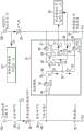
图1是可提供用于燃料调节的信号的测量系统的视图;FIG. 1 is a view of a measurement system that can provide a signal for fuel regulation;
图1A是具有三个混合点的燃烧器控制系统的视图;1A is a view of a burner control system with three mixing points;
图1B是燃烧器控制系统的视图,该燃烧器控制系统具有相对于至混合点的燃料流量的可选择质量流量约束装置;FIG. 1B is a view of a burner control system with a selectable mass flow restriction device relative to fuel flow to the mixing point;
图2是表示参考空气流的视图;FIG. 2 is a view showing a reference air flow;
图3是表示用于预混合的参考空气流的视图;3 is a view showing a reference air flow for premixing;
图4是表示被调节的气体(在本文中,“气体”可与“燃气”互换使用)流的视图;Figure 4 is a diagram representing a regulated flow of gas (herein, "gas" is used interchangeably with "gas");
图5是调节系统的第一操作状况的视图;5 is a view of a first operating condition of the adjustment system;
图6是调节系统的第二操作状况的视图;6 is a view of a second operating condition of the adjustment system;
图7是调节系统的第三操作状况的视图;7 is a view of a third operating condition of the adjustment system;
图8是调节系统的第四操作状况的视图;8 is a view of a fourth operating condition of the adjustment system;
图9是调节系统的第五操作状况的视图;9 is a view of a fifth operating condition of the adjustment system;
图10是调节系统的第六操作状况的视图;10 is a view of a sixth operating condition of the adjustment system;
图11是这样的视图,其示出调节控制方案调节在压力调节器正下游的气体压力的采集点处的气体压力;FIG. 11 is a view showing that the regulation control scheme regulates the gas pressure at the acquisition point of the gas pressure immediately downstream of the pressure regulator;
图12是这样示例的视图,其中调节控制作为独立反馈被施加以防护在所谓的并联定位系统中的空气约束阀和气体约束阀的位置;Figure 12 is a view of an example in which modulating control is applied as independent feedback to guard the position of an air restraint valve and an air restraint valve in a so-called parallel positioning system;
图13是燃烧器控制系统的视图,所述燃烧器控制系统具有冗余流动路径以及相对于燃料流量来说的可选择质量流量约束装置,以选择性地提供燃料流量至冗余流动路径;13 is a view of a combustor control system having redundant flow paths and selectable mass flow constraints relative to fuel flow to selectively provide fuel flow to the redundant flow paths;
图14是作为总体放大率的函数的传感器关系的图形的视图;14 is a graph of a graph of sensor relationships as a function of overall magnification;
图15是具有燃烧器燃料和空气混合物的燃烧器控制系统的视图,其中由传感器检测的燃料参数是可调节的;15 is a view of a burner control system having a burner fuel and air mixture in which fuel parameters detected by sensors are adjustable;
图16是具有燃烧器燃料和空气混合物的燃烧器控制系统的视图,其中由传感器检测的空气参数是可调节的;以及FIG. 16 is a view of a burner control system having a burner fuel and air mixture in which air parameters detected by sensors are adjustable; and
图17是具有燃烧器燃料和空气混合物的燃烧器控制系统的视图,其中跨过传感器所检测的空气和燃料参数都是可调节的。17 is a view of a burner control system with a burner fuel and air mixture in which both air and fuel parameters detected across sensors are adjustable.
具体实施方式Detailed ways
在本文中所描述和/或示出的实施方式中,本发明的系统和方法可包括一个或多个处理器、计算机、控制器、用户界面、无线和/或有线连接等等。In the embodiments described and/or illustrated herein, the systems and methods of the present invention may include one or more processors, computers, controllers, user interfaces, wireless and/or wired connections, and the like.
本说明书可提供一个或多个说明性的和具体的示例、或者实施本发明系统和方法的方案。可能存在实施本发明系统和方法的许多其它示例或者方法。This specification may provide one or more illustrative and specific examples, or approaches, for implementing the systems and methods of the present invention. There may be many other examples or methods of implementing the systems and methods of the present invention.
本发明的方法和系统可以以如下为特征:在参考空气压力、参考燃烧室压力和调节燃料压力之间的气动连接。气动连接可包含流动通道、流量阻碍装置和感测元件。该系统可提供反馈信号,该反馈信号可用于精确地调节燃料压力,从而得到被精确控制的空气燃料混合比。术语“阻碍(或阻碍装置)”和“约束(或约束装置)”在本文中可被互换地使用。术语“入口”和“出口”可属于流体装置。术语“端口”可指代入口或出口。术语“输入”和“输出”可属于电气装置或流体装置。The methods and systems of the present invention may feature a pneumatic connection between the reference air pressure, the reference combustion chamber pressure, and the regulated fuel pressure. Pneumatic connections may include flow channels, flow obstructions, and sensing elements. The system can provide a feedback signal that can be used to precisely adjust the fuel pressure, resulting in a precisely controlled air-fuel mixture ratio. The terms "obstructing (or obstructing means)" and "restraining (or restraining means)" are used interchangeably herein. The terms "inlet" and "outlet" may pertain to fluidic devices. The term "port" can refer to an inlet or an outlet. The terms "input" and "output" may pertain to electrical or fluidic devices.
本发明的系统不必需要压力调节器下游的机械调节。该系统不必需要可调节的节流阀、可调节的孔口、或者对于机械或气动压力放大器的调节。The system of the present invention does not necessarily require mechanical adjustment downstream of the pressure regulator. The system does not necessarily require adjustable throttles, adjustable orifices, or adjustments to mechanical or pneumatic pressure amplifiers.
另外,本发明的系统可控制用于各种各样的应用的空气燃料混合比,所述应用例如是预混合、空气燃料比例动力射流、平行定位动力射流等。Additionally, the system of the present invention can control the air-fuel mixing ratio for a wide variety of applications such as premixing, air-fuel ratio power jets, parallel positioning power jets, and the like.
该系统可实现用于如下的多种方法:空气燃料混合精度、燃料适应性、空气燃料比例混合、非线性混合曲线、自动调试、诊断、调制范围、燃料计量、燃料压力监视、空气压力监视、设置的版本控制、授权控制、安全和保护、故障保护操作。The system can implement a variety of methods for the following: air-fuel mixing accuracy, fuel adaptability, air-fuel ratio mixing, nonlinear mixing curve, auto-tuning, diagnostics, modulation range, fuel metering, fuel pressure monitoring, air pressure monitoring, Version control of settings, authorization control, security and protection, failsafe operations.
燃料空气比的精确控制可以是改善燃烧室(例如,燃烧器)的总体燃烧器性能和效率的最重要方面之一。Accurate control of the fuel-to-air ratio can be one of the most important aspects of improving the overall combustor performance and efficiency of a combustion chamber (eg, a combustor).
本说明书可示出,调节方法如何借助于与主空气质量流量相关的第一质量流量传感器来测量伺服空气质量流量,以及调节方法如何借助于与主燃料流量相关的第二质量流量传感器来测量伺服空气流量。This description can show how the adjustment method measures the servo air mass flow with the aid of a first mass flow sensor related to the main air mass flow, and how the adjustment method measures the servo air mass flow with the aid of a second mass flow sensor related to the main fuel flow. air flow.
本说明书还可示出,该系统如何通过第一嵌入方法来实现故障保护,所述第一嵌入方法通过检测并测量传感器读数漂移的量来检测到混合物由于传感器漂移而会进入不安全的比率、首先校正所测量的传感器漂移量或者当所测量的漂移量超过预定阈值时关闭该应用。可针对过滤器或孔口约束的变化来施加校正。This specification may also show how the system achieves failsafe through a first embedded method that detects and measures the amount of sensor reading drift that the mixture is entering an unsafe ratio due to sensor drift, The measured sensor drift is first corrected or the application is closed when the measured drift exceeds a predetermined threshold. Corrections can be applied for changes in filter or orifice constraints.
本说明书还可示出,该系统如何通过第二嵌入方法来实现故障保护,所述第二嵌入方法会检测到由于燃料侧过滤器的约束增加,混合比有可能进入不安全情形,并且当超过某个预定阈值时将关闭该应用。This specification can also show how the system is failsafe through a second embedded method that detects that the mixing ratio is likely to enter an unsafe condition due to increased fuel-side filter constraints, and when exceeding The app will be closed when a predetermined threshold is reached.
本说明书还可示出,安装者能够如何编程最佳地匹配该应用的实质上任何曲线,该曲线示出作为燃烧器能力的函数的空气质量流量和燃料质量流量的混合比,以及该系统能够如何基于所调试并批准的设定点来调节空气质量流量和燃料质量流量的混合比。This specification also shows how an installer can program virtually any curve that best matches the application showing the mixture ratio of air mass flow and fuel mass flow as a function of burner capacity, and how the system can How to adjust the air mass flow and fuel mass flow mix ratio based on the tuned and approved set points.
一个因素可以是现有技术的调节装置可具有内含于其中的可被解决的问题。所述问题可以包括:难以接近调节装置、给安装者的低劣信号反馈、不可能固定、锁定或固化所测试并批准的设置、需要手动调节、没有自动调试、没有诊断、针对不同热容量的编程混合比可能性受限、对于安全和燃烧质量来说依赖于安装者的技能和耐心、仅针对零压阀系统(zero governor system)有效、对于非零压阀系统需要不同的方案、以及针对设置已经从调试值漂移的无检测或粗略检测。One factor may be that prior art adjustment devices may have inherent problems that can be solved. The problems can include: difficult access to adjustment devices, poor signal feedback to installer, impossible to fix, lock or cure tested and approved settings, manual adjustment required, no automatic tuning, no diagnostics, programming mix for different thermal capacities The ratio possibilities are limited, depend on the skill and patience of the installer for safety and combustion quality, only valid for zero governor systems, require a different solution for non-zero governor systems, and have No detection or coarse detection of drift from debug values.
阀可安装在各种类型的位置中,这意味着在许多情形中读取调节螺钉的标记以及对调节螺钉进行调节可能会是困难的。在典型的气体燃烧器中,其可能难以接近或者调节。因此,在燃烧器的位置处调节装置的视觉反馈可能是低劣的。The valve can be installed in various types of positions, which means that reading the markings of the adjusting screw and adjusting the adjusting screw can be difficult in many cases. In a typical gas burner, it can be difficult to access or adjust. Therefore, the visual feedback of the adjustment device at the position of the burner may be inferior.
将调节装置固定或固化在有利的设置中而不干扰所实现的设置,这可能会是很困难的或者不可能的,并且是耗时的。It can be difficult or impossible and time consuming to fix or cure the adjustment device in an advantageous setting without interfering with the setting achieved.
放置盖以从视野中隐藏调节螺钉不必然地固定所述设置。当安装所述盖时,可能容易接触到调节螺钉或者意外地解除对于设置的调节。任何罩或盖对于安装者来说应当是可移除的,并且能够不被察觉地由某些个人移除以改变锅炉的设置。Placing a cover to hide the adjustment screws from view does not necessarily fix the setting. When the cover is installed, it may be easy to gain access to the adjustment screws or to unintentionally release the adjustment to the setting. Any hood or cover should be removable to the installer and unobtrusively removed by some individual to change the boiler's settings.
现有技术的系统可能需要手动调节。在调试期间,安装者可能附接临时燃烧传感器以读取燃烧质量。基于测量结果,安装者可能需要根据限定的程序来转动螺钉,直到燃烧质量是良好且可接受的。在每个调节步骤之后,燃烧过程和燃烧器可能需要随着时间的推移而稳定化。该程序可能需要耐心、工具、时间和安装者的技能。对于空气气体比例调节系统来说,可能存在能够由调节螺钉来调节的两个设置。Prior art systems may require manual adjustment. During commissioning, installers may attach temporary combustion sensors to read combustion quality. Based on the measurements, the installer may need to turn the screw according to a defined procedure until the burn quality is good and acceptable. After each tuning step, the combustion process and burner may need to be stabilized over time. The procedure may require patience, tools, time and the skill of the installer. For an air to gas ratio adjustment system, there may be two settings that can be adjusted by the adjustment screw.
原理上说,可应用步进马达以使安装者转动调节装置。然而,一旦断电,步进马达可能会丢失其位置并且需要重置步数。可能需要独立的位置反馈以验证调节装置处于正确的位置。因此,可能需要一个或两个致动器以及一个或两个反馈系统,以仅用于随时间的推移而保持恒定的设置。这些因素可能使得经济上难以施加自动调试。In principle, a stepper motor could be used to allow the installer to turn the adjustment device. However, in the event of a power failure, the stepper motor may lose its position and the step count needs to be reset. Independent position feedback may be required to verify that the adjustment device is in the correct position. Therefore, one or two actuators and one or two feedback systems may be required just to maintain a constant setting over time. These factors may make it economically difficult to impose automatic tuning.
在系统的操作期间,可能发生多种情况,为此可能需要进行感测和诊断。例如,建筑调节器(building regulator)可能破裂从而导致高气体供应压力;某物可能损坏或堵塞气体供应管线从而导致气体供应不足,以及堵塞空气供应管线从而导致空气供应不足。电源可能发生一些情况从而导致产生比预期的更高或更低的风扇速度。空气约束阀可能出问题。某物可能会堵塞烟道从而导致空气流量改变并且导致更高的燃烧室压力。伺服流动通道中的过滤器可能由于污染而被阻塞。传感器可能从其设置漂移。化学气体成分可能随着时间的推移而改变。伺服通道中的一个中的其中一个孔口可能被堵塞。在调试期间某人可能犯错。气量计可能出问题。可能需要不同的开关和/或传感器以检测将要发生的事件。零压阀系统或压差传感器对于应用诊断来说可能仅具有有限的作用。During operation of the system, a variety of conditions may occur for which sensing and diagnostics may be required. For example, a building regulator may rupture resulting in high gas supply pressure; something may damage or block the gas supply line resulting in insufficient gas supply, and block the air supply line resulting in insufficient air supply. Something may have happened to the power supply that resulted in higher or lower fan speeds than expected. There may be a problem with the air restriction valve. Something could clog the flue causing changes in air flow and resulting in higher combustion chamber pressures. The filter in the servo flow channel may be blocked due to contamination. The sensor may drift from its setting. Chemical gas composition may change over time. One of the orifices in one of the servo channels may be blocked. Someone might make a mistake during debugging. There may be a problem with the gas meter. Different switches and/or sensors may be required to detect impending events. Zero-pressure valve systems or differential pressure sensors may only be of limited use for application diagnostics.
可能期望有存在编程的混合比。从任何零压阀系统(其中,在零流量周围进行调节的流量传感器基本上也是零压阀)得到的空气和气体的混合比可被描述为一阶函数,例如y=ax+b,其中y代表燃料质量流量,x代表空气质量流量,a限定混合比的陡度(由节流阀螺钉和可调节的孔口限定),以及b限定由偏置螺钉或通过传感器的流限定的偏移。It may be desirable to have a programmed mix ratio. The mixing ratio of air and gas obtained from any zero pressure valve system (where the flow sensor that adjusts around zero flow is also essentially a zero pressure valve) can be described as a first order function, eg y=ax+b, where y represents the fuel mass flow, x represents the air mass flow, a defines the steepness of the mixing ratio (defined by the throttle screw and adjustable orifice), and b defines the offset defined by the bias screw or flow through the sensor.
可能期望具有气体质量流量读数。气体供应商可能在一年中改变气体的化学成分以改善冬季和夏季的需求,因为许多系统依赖于压力调节器。可改变气体成分以使得沃泊指数(比热/密度)保持恒定,这意味着典型的应用将不必由于成分改变而遭受错误调节。即使当传感器被批准用于天然气时,流量传感器的主要缺点可能在于,所述传感器通过热传递来测量流量,这意味着读数依赖于各种类型的特定气体参数,例如密度、粘度、比热和比热传导系数。当所使用的气体的化学成分随时间的推移而改变时,在质量流量传感器中可能出现读数误差。由于该原因,流量传感器不一定适用于在化学成分随时间的推移而改变的情况下精确地测量气态流量。It may be desirable to have gas mass flow readings. Gas suppliers may change the chemical composition of the gas throughout the year to improve winter and summer demand, as many systems rely on pressure regulators. The gas composition can be changed so that the Wobbe index (specific heat/density) remains constant, which means that typical applications will not have to suffer from misadjustment due to compositional changes. Even when the sensor is approved for natural gas, the main disadvantage of a flow sensor can be that the sensor measures flow by heat transfer, which means that the readings depend on various types of specific gas parameters such as density, viscosity, specific heat and Specific heat transfer coefficient. Reading errors can occur in mass flow sensors when the chemical composition of the gas used changes over time. For this reason, flow sensors are not necessarily suitable for accurately measuring gaseous flow with changes in chemical composition over time.
可能期望有漂移检测。在一些系统中,当没有达到某个压力目标时,可能使用压力开关来关闭该应用。当该应用在相对低的功率水平下运行时,可能难以区分可接受的漂移和不可接受的漂移。Drift detection may be desired. In some systems, a pressure switch may be used to shut down the application when a certain pressure target is not reached. When the application is operating at relatively low power levels, it can be difficult to distinguish between acceptable and unacceptable drift.
可能期望有空气和燃料流动路径的冗余构造。燃烧器系统(例如,预混合燃烧器应用、强制通风燃烧器应用和/或其他燃烧器应用)或者其他系统可能产生与主空气流动路径有关的压差信号、以及与主燃料流动路径有关的压差信号。该系统中的混合点下游的压力可被认为是这两个压差的下游(库(sink))参考压力。空气通道中的混合点上游的压力可被认为是空气压差的(源)参考压力。燃料通道中的混合点上游的压力可被认为是压差的(源)参考压力。It may be desirable to have redundant configurations of air and fuel flow paths. Burner systems (eg, premix burner applications, forced draft burner applications, and/or other burner applications) or other systems may generate differential pressure signals related to the main air flow path, as well as pressure related to the main fuel flow path. poor signal. The pressure downstream of the mixing point in the system can be considered the downstream (sink) reference pressure of these two differential pressures. The pressure upstream of the mixing point in the air passage can be considered as the (source) reference pressure for the air pressure differential. The pressure upstream of the mixing point in the fuel passage may be considered the (source) reference pressure for the differential pressure.
冗余构造可包括第一流动路径(例如,主空气流动路径)、第二流动路径(例如,主燃料流动路径)、第三流动路径(例如,冗余流动路径)、和/或一个或多个其他流动路径。第一流动路径可被连接到空气源(例如,空气源压力P1)和混合点下游的压力(例如,库压力P0)。第一流动路径可配置有第一传感器(例如,质量流量传感器、压差传感器和/或其他传感器),其可产生与通过第一流动路径的流体流量相关的读数。第二流动路径可连接到空气源、燃料源(例如,燃料源压力P2),以及连接到库压力P0。第二流动路径可配置有第二传感器(例如,质量流量传感器、压差传感器和/或其他传感器),其可产生与通过相对于第一流动路径来说的第二流动路径的流体流量有关的读数。The redundant configuration may include a first flow path (eg, a primary air flow path), a second flow path (eg, a primary fuel flow path), a third flow path (eg, a redundant flow path), and/or one or more other flow paths. The first flow path may be connected to an air source (eg, air source pressure P 1 ) and a pressure downstream of the mixing point (eg, bank pressure P 0 ). The first flow path may be configured with a first sensor (eg, a mass flow sensor, a differential pressure sensor, and/or other sensor) that may generate readings related to fluid flow through the first flow path. The second flow path may be connected to an air source, a fuel source (eg, fuel source pressure P 2 ), and to a reservoir pressure P 0 . The second flow path may be configured with a second sensor (eg, a mass flow sensor, a differential pressure sensor, and/or other sensor) that may generate a correlation with fluid flow through the second flow path relative to the first flow path reading.
第三流动路径可以以第一布置连接到空气源和库压力P0,或者以第二布置连接到空气源、燃料源和库压力P0。第三流动路径可配置有开关阀,并且取决于开关阀的状态,第三流动路径可处于第一布置或第二布置。此外,第三流动路径可配置有第三传感器(例如,质量流量传感器、压差传感器或其他传感器),其在第三流动路径处于第一布置时可返回与通过第一流动路径的流体流量有关的读数并且是第一传感器的冗余,并且在第三流动路径处于第二布置时可返回与通过第二流动路径的流体流量有关的读数并且是第二传感器的冗余。The third flow path may be connected to the air source and reservoir pressure P 0 in a first arrangement, or to the air source, fuel source, and reservoir pressure P 0 in a second arrangement. The third flow path may be configured with an on-off valve, and depending on the state of the on-off valve, the third flow path may be in the first arrangement or the second arrangement. Additionally, the third flow path may be configured with a third sensor (eg, a mass flow sensor, a differential pressure sensor, or other sensor) that may be returned in relation to fluid flow through the first flow path when the third flow path is in the first arrangement and is redundant to the first sensor and may return a reading related to fluid flow through the second flow path and is redundant to the second sensor when the third flow path is in the second arrangement.
在一些情况下,来自第三传感器的读数(例如,测量结果或测量值)可与来自第一传感器和第二传感器中的一者或多者的读数进行比较,以识别燃烧器系统中的故障。当识别到故障时,可触发警告或警报。故障可包括以下中的一者或多者:流动路径被堵塞或部分堵塞;传感器未正确地操作;和/或与燃烧器或其部件的操作有关的一个或多个其他问题。In some cases, readings (eg, measurements or measurements) from the third sensor may be compared to readings from one or more of the first and second sensors to identify faults in the combustor system . When a fault is identified, a warning or alarm can be triggered. Faults may include one or more of: blocked or partially blocked flow paths; sensors not operating properly; and/or one or more other problems with the operation of the combustor or its components.
本发明的系统可包括:(1)调节系统;(2)调节方法;以及(3)调节产品,其解决已知的问题并且提供用于气体燃烧器应用系统(例如,空气气体比例预混合、空气气体比例强制通风和/或并联定位强制通风)的解决方案。The system of the present invention may include: (1) a conditioning system; (2) a conditioning method; and (3) conditioning products that address known problems and provide systems for gas burner applications (eg, air-to-gas ratio premixing, Air-to-Gas Proportional Forced Ventilation and/or Parallel Positioned Forced Ventilation).
本发明的控制系统可消除与机械调节装置以及利用气态流体的流量传感器进行流量测量有关的缺点。该控制系统可排除机械调节的需要。此外,该系统可这样组合燃料和空气的测量,以使得当仅空气流动通过第一和第二传感器时,可使用第二流量传感器来测量燃料和空气两者相对于彼此。The control system of the present invention eliminates the disadvantages associated with mechanical adjustment devices and flow measurement with flow sensors for gaseous fluids. This control system eliminates the need for mechanical adjustment. Additionally, the system may combine the measurements of fuel and air such that when only air is flowing through the first and second sensors, the second flow sensor may be used to measure both fuel and air relative to each other.
图1是可提供用于燃料调节的信号的测量系统15(例如,感测模块)的视图。示例性燃料可以是本文所讨论的说明性示例中的天然气,但是其他种类的燃料也可适用于本发明的系统和方法。该系统可包括两个伺服质量流入口。一个入口17可连接到具有参考空气压力的参考空气流动导管。另一入口16可连接到具有调节的压力的气体流动导管。FIG. 1 is a view of a measurement system 15 (eg, a sensing module) that may provide signals for fuel regulation. An exemplary fuel may be natural gas in the illustrative examples discussed herein, although other types of fuels may be suitable for use in the systems and methods of the present invention. The system may include two servo mass flow inlets. One
系统15可包括一个出口18,该出口连接到在锅炉中的入口点下游的参考点,在该参考点处空气和气体已经被混合到一起,参考点例如在燃烧室处或在混合装置的下游。该系统还可包括三个左右的过滤器19、20、30,以从进入的空气、进入的气体以及可能由于在点火期间的压力波动而回流的流出空气-气体过滤掉颗粒。该系统可包括四个左右的流量阻碍装置21、22、23、24,其通常是孔口。流量阻碍装置可以在尺寸和阻碍水平方面彼此不同。该系统可包括两个质量流量传感器25、26,其产生取决于流量的(电)信号。The
不必测量燃料通道中的压力。可以测量通过传感器的质量流量;或者在传感器针对压差被标定的情况下,可以测量传感器上的压降。由此,可计算对于燃料通道中的压力的指示。所计算的压力不必是精确值。It is not necessary to measure the pressure in the fuel passage. The mass flow through the sensor can be measured; or the pressure drop across the sensor can be measured if the sensor is calibrated for differential pressure. From this, an indication of the pressure in the fuel passage can be calculated. The calculated pressure need not be an exact value.
虽然该系统在上文被描述并且在图1中被示出为具有两个伺服质量流入口(例如,入口16和17)和一个出口(例如,出口18),但是该系统可具有一个伺服质量流入口和两个出口。在一个示例中,一个入口17可连接到具有参考空气压力的参考空气流动导管,两个出口中的一个(例如,出口18)可连接到在锅炉中的入口点17下游的参考点,在该参考点处空气和气体已经被混合到一起,参考点例如在燃烧室处或在混合装置的下游,并且入口16可被转换为第二出口。这种构造可允许调节与空气压力相比来说相对低的燃料压力。Although the system is described above and shown in FIG. 1 as having two servo mass flow inlets (eg,
该系统可包括从正空气参考压力(A)27至较低压力(C)28燃烧室的第一伺服流动通道141。第一伺服通道可包括入口过滤器(E)20、质量流量传感器(H)25、质量流量阻碍装置(I)23和回流出口过滤器(G)30。质量流量传感器(H)25可产生第一电信号(#1)31,其反映通过第一质量流动通道的空气的伺服质量流量。该系统可包括从正空气参考压力(A)至中间压力连接点(D)的第二伺服流动通道142。第二伺服通道可包括入口过滤器(E)20、质量流量传感器(J)26和质量流量阻碍装置(K)24。质量流量传感器26可产生第二电信号(#2)32,其反映通过第二质量流动通道的空气的伺服质量流量。The system may include a first
该系统可包括从正调节气体压力(B)34至中间压力连接点(D)33的第三伺服流动通道143。第三伺服通道可包括入口过滤器(F)19、止回阀(L)35以及并联的一个或多个质量流量阻碍装置(M)21。止回阀35可被打开以允许气体从调节气体(B)34采集点流至中间压力点(D)33或者从中间压力点(D)33流至调节气体压力(B)34采集点。止回阀(L)35可被关闭(关断)以防止气体从中间压力点(D)33流至调节气体压力采集点、或者流至中间压力点(D)33(因为当阀被关闭时流仍被允许从中间压力点流至燃烧室)。The system may include a third
该系统可包括从中间连接点(D)33至较低压力燃烧室(C)28的第四伺服流动通道144。第四伺服通道可包括流量阻碍装置(N)22和空气过滤器(G)30。用于多个通道的过滤器可被组合成一个组合过滤器。The system may include a fourth
图1A是可以为图1中的系统15的变型的燃烧器控制系统151的视图。空气供应源37可提供空气至第一入口17,该第一入口具有至第一质量流量传感器25和第二质量流量传感器26的入口的连接。来自流量传感器25的第一信号输出31可被连接到处理器152的输入,来自流量传感器26的第二信号输出32可被连接到处理器152的另一输入。流量传感器25的出口可连接到系统151的第一出口153。出口153可被连接到第一混合点154。流量传感器26的出口可连接到第二混合点33。FIG. 1A is a view of a
燃料供应源45可连接到可变质量流量约束装置155。约束装置155的下游端可连接到系统151的第二入口16。处理器152的输出可提供信号以调节或改变约束装置155。
入口16可连接到混合点33。混合点33可在下游连接到系统151的第二出口156。出口156可连接到第三混合点157。
空气供应源37可连接到恒定空气流量约束装置158。约束装置158可在下游连接到第一混合点154。混合点154可在下游连接到可变空气流量约束装置159,该可变空气流量约束装置继而可被连接到第三混合点157。混合点157可在下游连接到燃烧室162。数据存储存储器163可连接到处理器152。
图1B是可以为图1的系统15的变型的燃烧器控制系统161的视图。空气供应源37可将空气提供至第一入口17,该第一入口具有至第一质量流量传感器25和第二传感器26的入口的连接。来自流量传感器25的第一信号输出31可连接到处理器152的输入,来自流量传感器26的第二信号输出32可连接到处理器152的另一输入。流量传感器25的出口可连接到系统161的出口18。出口18可连接到燃烧室162。流量传感器26的出口可连接到混合点33。FIG. 1B is a view of a
燃料供应源45可连接到可变质量流量约束装置155。约束装置155的下游端可连接到系统161的第二入口16。处理器152的输出可被提供至可变质量流量约束装置155。
入口16可在下游连接到质量流量约束装置21。约束装置21可在下游连接到混合点33。一个或多个附加约束装置可与约束装置21并联地连接。例如,约束装置165可具有连接至阀166的入口,阀166连接到入口16。约束装置165的出口端可连接到混合点33。如果需要或者期望的话,另一约束装置167可具有连接到阀168的入口,阀168连接到入口16。约束装置167的出口可连接到混合点33。阀166和168可打开或关闭以分别接入或断开约束装置165和167。
图2是表示参考空气流的视图。在主空气流动通道中,可通过诸如风扇或泵的致动器在空气供应源入口(AA)37处产生压差。风扇或泵可导致如下事实,与在下游在出口(C)28处的相对低的压力相比,在上游在入口(AA)37处出现相对高的压力。致动器可被放置成靠近入口,但是也可被放置在空气通道中的其他位置处。为了调节参考空气(质量)流量,有可能改变致动器的速度或者有可能操作可调节的空气流量约束装置,例如空气阀(AB)38。空气阀(AB)38不必强制性地位于空气通道中。FIG. 2 is a view showing a reference air flow. In the main air flow channel, a pressure differential may be created at the air supply inlet (AA) 37 by an actuator such as a fan or pump. A fan or pump may lead to the fact that a relatively high pressure occurs upstream at inlet (AA) 37 compared to a relatively low pressure downstream at outlet (C) 28 . The actuator can be placed close to the inlet, but can also be placed elsewhere in the air channel. To adjust the reference air (mass) flow, it is possible to vary the speed of the actuator or to operate an adjustable air flow restriction, such as the air valve (AB) 38 . The air valve (AB) 38 does not necessarily have to be located in the air passage.
在燃烧室(C)28的上游,可定位燃烧器头部来代表流量约束装置(AC)39。燃烧器头部流量约束装置(AC)39可以是用于调节的重要特征,因为其可在参考点(A)27和参考点(C)28之间产生压差,该压差为用于馈送至感测模块15的通燃烧器头约束装置39的主空气流量的函数。取代燃烧器头部阻碍装置,专用恒定流量阻碍装置代替燃烧器头部阻碍装置来产生参考压差。在燃烧器头部可能由于某些原因而改变(例如,随着时间推移改变,或者流动能力改变)的情况下,可应用专用阻碍装置。Upstream of the combustion chamber (C) 28 , a combustor head may be positioned to represent a flow restriction (AC) 39 . The burner head flow restriction (AC) 39 can be an important feature for regulation as it can create a pressure differential between reference point (A) 27 and reference point (C) 28 which is used for feeding A function of primary air flow through
图3是表示用于预混合应用的参考空气流的视图。对于其中空气和气体在燃烧器头部之前混合的预混合应用,有可能利用混合装置的空气侧部段的流量阻碍装置(例如,文丘里管的入口)。在预混合的情况下,混合装置流量约束装置(AD)41可以是用于调节的重要特征,因为其可在参考点(A)27和参考点(C”)42之间产生压差,该压差为被用于馈送至感测模块15的通过混合装置约束装置41和混合点(AE)43的主空气流量的函数。Figure 3 is a view showing a reference air flow for a premix application. For premixing applications where air and gas are mixed before the burner head, it is possible to utilize the flow obstructing means of the air side section of the mixing means (eg the inlet of the venturi). In the case of premixing, the mixing device flow restriction (AD) 41 can be an important feature for regulation because it can create a pressure differential between reference point (A) 27 and reference point (C") 42, which The differential pressure is a function of the primary air flow used to feed the
图4是表示调节气体流的视图。在主气体流动通道中,可将高于燃烧室压力(C/C”)的入口压力供应(GA)45至系统。为了安全的原因,在气体通道中可存在第一安全截止阀(GB)47。为了安全的原因,可存在第二安全截止阀(GD)48。安全截止阀可以被打开或者被关闭。可调节流量约束阀(GC)49可以是可用的,以将气体流量调节至在最小值和最大值之间的期望水平。可调节流量约束阀49可处于在最大关闭和最大打开之间的任何位置。质量流量约束阀(GC)49可被定位在第一安全截止阀(GB)47和第二安全截止阀(GD)48之间,但是还可能将质量流量约束阀(GC)49定位在第一安全截止阀(GB)47的上游,和在第二安全截止阀(GD)48下游且在用于气体压力的压力采集点(B)34的上游。FIG. 4 is a view showing the flow of regulated gas. In the main gas flow channel, an inlet pressure (GA) 45 above the combustion chamber pressure (C/C") may be supplied to the system. For safety reasons, there may be a first safety shut-off valve (GB) in the
在气体采集点(B)34下游且在燃烧室压力(C)28或混合装置压力(C”)42(图3)上游,可存在诸如燃烧器孔口(GE)51(图4)的流量约束装置,其在点(B)34和(C)28(图1)之间产生压差,该压差为用于馈送至感测模块15的气体流量的函数。燃烧器孔口51后的压力可以是燃烧室PCC(C)28或PPC(C")46(图4)。Downstream of gas collection point (B) 34 and upstream of combustor pressure (C) 28 or mixing device pressure (C") 42 (FIG. 3), there may be a flow such as combustor orifice (GE) 51 (FIG. 4) Constraints that create a pressure differential between points (B) 34 and (C) 28 ( FIG. 1 ) as a function of gas flow for feeding the
可能期望的是,相对于空气参考质量流量来调节气体质量流量,以使得气体和空气根据预定比率在燃烧室中或在混合装置室等等中混合在一起。预定的混合比可涉及燃烧排放气体(例如,CO2、CO和NOx)的产生。在不同的应用之间,最佳混合比可能略微不同。此外,最佳混合比可能在给定应用的热容量带上略微不同,这意味着相比于在中等热容量状况下或者在最大热容量状况下,燃烧器在低热容量状况下可能需要不同的混合比。此外还可能的是,启动状况与燃烧操作状况需要不同的混合比。总之,混合比可能需要是灵活的以覆盖不同的状况,并且在其设置中是可重复的以一次又一次地获得相当的燃烧结果。It may be desirable to adjust the gas mass flow relative to the air reference mass flow so that the gas and air mix together according to a predetermined ratio in the combustion chamber or in the mixing device chamber or the like. The predetermined mixing ratio may involve the production of combustion exhaust gases (eg, CO2, CO, and NOx). The optimum mix ratio may vary slightly from application to application. Furthermore, the optimum mix ratio may vary slightly over the heat capacity band of a given application, which means that the burner may require a different mix ratio at low heat capacity conditions than at medium heat capacity conditions or at maximum heat capacity conditions. It is also possible that start-up conditions and combustion operating conditions require different mixing ratios. In summary, the mixing ratio may need to be flexible to cover different conditions and repeatable in its setting to obtain comparable combustion results time and time again.
可以注意设置和调试。为了设置、使用和核查该系统以用于适当的燃烧,调节系统可考虑到多个不同的操作状况。Settings and debugging can be taken care of. In order to set up, use and verify the system for proper combustion, the adjustment system can take into account a number of different operating conditions.
图5是调节系统的第一操作状况的视图。在调节系统的第一操作状况中,其中感测模块15中的止回阀35关闭,并且其中气体流动通道与感测模块分离,并因此不必然地影响传感器读数31和32,可产生通过主空气流动管道(右侧)的离散数量的不同空气流量水平,其可导致在燃烧器头部约束装置上的离散数量的不同压差,这导致通过感测模块15的第一、第二和第四伺服通道的离散数量的伺服流量,这将产生质量传感器(#1)25和质量传感器(#2)26的离散数量的传感器读数。空气供应压力和空气供应温度不必被调节,但是可至少被控制,使其代表与当存储传感器读数时的情形相匹配的状况。在此情形中,包含质量流量传感器(#1)25的第一伺服通道可以与包含质量流量传感器(#2)26的第二通道和第四伺服通道并联。两个并联的通道可以由同一源来馈送并且质量流可被释放到同一库。另外,质量流可通过同一入口过滤器20和出口过滤器30以及流量阻碍装置22、23、24,因为质量流量传感器25、26可以是恒定的不变部件,这意味着传感器(#2)26读数和传感器(#1)25读数的比率应当是一致的且可重复的。分别作为信号31和32的传感器(#1)25和传感器(#2)26的传感器读数可作为参考值被存储在存储装置54中,表示为S'1[1,2,...,n]和S'2[1,2,...,n]。5 is a view of a first operating condition of the adjustment system. In the first operating condition of the conditioning system, in which the
对应于在存储装置54处的读数的可以是符号101处的离散数量的事件S4[1,2,...、n],在符号101处的离散数量的事件S4[1,2,...、n]具有在受控空气供应源102和可控制的空气阀38之间的连接。在设置期间,安装者在某种程度上能够通过空气供应源或空气阀来控制空气供应,但是在操作模式下空气流可以由外部装置控制,并且不可被我们的调节系统通达。关系仍然存在,但是不必然地控制该源。Corresponding to the reading at
图6是调节系统的第二操作状况的视图。在调节系统的第二操作状况中,其中感测模块15中的止回阀35打开,两个安全截止阀47和48中的至少一个可以关闭,并且气体流动通道可转变(被认为是)为从感测模块15至燃烧室或混合装置室的另一空气流动通道,同样,可产生通过主空气流动管道(右侧)的离散数量的不同空气流量水平,其可导致在燃烧器头部约束装置39上的离散数量的不同压差,这将导致通过感测模块15的第一、第二、第三和第四伺服通道的离散数量的伺服流量,并且这将产生质量传感器(#1)25和质量传感器(#2)26的离散数量的传感器读数。空气供应压力和空气供应温度不必被调节,但是至少被控制,使其代表与当存储传感器读数时的情形相匹配的状况。在此情形中,包含质量流量传感器(#1)25的第一伺服通道可以并联于包含质量流量传感器(#2)26的第二、第三和第四伺服通道。6 is a view of a second operating condition of the adjustment system. In the second operating condition of the regulation system, wherein the
两个并联的通道可以由同一源来馈送并且质量流可被释放到同一库。另外,质量流可通过同一入口过滤器,但是在该情况中气体入口过滤器可起到第二出口过滤器的作用,流量阻碍装置以及质量流量传感器可以都是恒定的不变的部件,这意味着传感器(#2)26读数32和传感器(#1)25读数31的比率应当是一致的且可重复的(伺服空气流量也穿过燃烧器孔口阻碍装置,对于该操作状况,忽略该燃烧器孔口,因为该孔口的截面面积针对主气体流量来设置尺寸,并且事实上对于比主流量小得多的伺服空气流量来说可被认为是无限大)。传感器(#1)25和传感器(#2)26的传感器读数可作为参考值被存储在存储装置54中,表示为S~1[1,2,...,n]和S~2[1,2,...,n](或任何其他表示)。The two parallel channels can be fed by the same source and the mass flow can be released to the same bank. Alternatively, mass flow can pass through the same inlet filter, but in this case the gas inlet filter can function as a second outlet filter, the flow obstruction device and the mass flow sensor can both be constant components, which means The ratio of sensor (#2) 26 reading 32 to sensor (#1) 25 reading 31 should be consistent and repeatable (servo air flow also passes through the burner orifice obstruction, ignore the combustion for this operating condition orifice, since the cross-sectional area of this orifice is sized for the main gas flow, and in fact can be considered infinite for a servo air flow that is much smaller than the main flow). The sensor readings of sensor (#1) 25 and sensor (#2) 26 may be stored in
对应于在存储装置54处的读数的可以是在符号101处的离散数量的事件S4[1,2,...、n],在符号101处的离散数量的事件S4[1,2,...、n] 具有在受控空气供应源102和可控制的空气阀38之间的连接。Corresponding to the reading at
图7是调节系统的第三操作状况的视图。燃烧传感器(混合比)56可在符号103处提供测量燃烧结果。可在符号104处提供目标燃烧结果。所测量的燃烧结果与目标燃烧结果之间的差可在符号105处被确定为误差。如在符号106处表示的,可借助于调节来自气体供应源102的气体流量来改变所测量的燃烧结果,以减小或消除在所测量的燃烧结果与目标燃烧结果之间的误差或差。7 is a view of a third operating condition of the adjustment system. Combustion sensor (mix ratio) 56 may provide measured combustion results at
在调节系统的第三操作状况中,其中感测模块15中的止回阀35打开,所有安全截止阀47和48都可打开。传感器(#1)25可测量并联于主空气流量的空气质量流量,并且所测量的流量可与主空气质量流量具有直接关系。传感器(#2)26可测量位于空气参考点27和中间压力点33之间的空气质量流量,中间压力点33在在通道三和四之间。由于气体质量流量,可导致在燃烧器孔口51上的压差,其形成在感测模块15上的第二压差。由于主空气流量的方向以及在燃烧器孔口51上的匹配压差,在伺服通道三的入口处在感测模块15上的气体入口压力34可高于在通道四和通道一下游的出口压力。在伺服通道三和伺服通道四中的流量阻碍装置可被选择成使得,中间压力处于在气体入口压力34和混合物出口压力28之间的某处,并且小于对应的参考空气入口压力27。In the third operating condition of the regulation system, in which the
对于每个离散数量的空气质量流量与气体质量流量的组合来说,可捕获传感器(#1)25读数31和传感器(#2)26读数32的唯一且离散数量的匹配组合。在存储装置54处,传感器(#1)25的读数31和传感器(#2)26的读数32可作为参考值被存储,用于该应用的经调试的多个有效且批准的设置,表示为S1[1,2,...,n]和S2[1,2,...,n];For each discrete number of air mass flow and gas mass flow combinations, a unique and discrete number of matching combinations of sensor (#1) 25
其中,通过调节气体质量流量约束阀49,将用于每个离散空气质量流量的气体质量流量调节至如下水平,该水平给出被临时安装并处理的燃烧传感器56的可接受读数。Therein, by adjusting the gas mass
对应于在存储装置54处的读数的可以是在符号101处的离散量的事件S4[1,2,...、n]以及在103处的S3[1,2,…,n],在符号101处的离散量的事件S4[1,2,...、n]具有在受控空气供应源102和可被控制的空气阀38之间的连接,在103处的S3[1,2,…,n]具有在受控空气供应源和受控气体供应源的混合比之间的连接。Corresponding to the reading at
可以注意到传递函数。传递函数可以从针对上述操作状况的传感器(#1)25和传感器(#2)26的离散数量的所存储的传感器读数来生成,其应当覆盖在最小值和最大值之间的连续范围。The transfer function can be noticed. The transfer function may be generated from a discrete number of stored sensor readings of sensor (#1) 25 and sensor (#2) 26 for the operating conditions described above, which should cover a continuous range between the minimum and maximum values.
第一传递函数S'2=F1(S'1)可以描述代表如下情形中传感器读数的曲线:其中止回阀35被关闭,且其中安全阀47和48被打开还是关闭没有影响。The first transfer function S'2=F1(S'1) may describe a curve representing sensor readings in situations where
第二传递函数S~2-S'2=F2(S~1,S'1)可描述这样的曲线,其示出了在预吹扫情形期间止回阀35关闭和止回阀35打开之间的区别。预吹扫可以意味着,当安全截止阀47和48被关闭时相当大的空气流量被吹过锅炉应用,以从该应用清洁掉任何未燃烧的气态成分。该函数可描述用于在伺服通道三(气体伺服通道)中过滤器清洁和孔口打开的参考情形。The second transfer function S~2-S'2=F2(S~1,S'1) may describe a curve showing the difference between
第三传递函数S2=F3(S1)可描述示出传感器读数的曲线,所述传感器读数反映了在最小能力和最大能力之间的气体质量流量和空气质量流量的通过调试和批准的混合比的曲线,在调试过程期间已经验证并批准了合适的燃烧结果。The third transfer function S2 = F3 ( S1 ) may describe a curve showing sensor readings reflecting the adjusted and approved mix ratios of gas mass flow and air mass flow between minimum and maximum capacity curve, suitable combustion results have been verified and approved during the commissioning process.
可以注意到运行模式(运行模式=第六操作状况)。在已经测量并存储上述传感器读数31和32并且已经在软件中建立了传递函数之后,该应用可能准备好通过重复前述批准的情形来在不存在安装者或燃烧结果传感器56(图7)的前提下无人值守地运行。The operating mode can be noted (operating mode=sixth operating condition). After the
在运行模式期间,空气质量流量可由风扇/鼓风机速度和/或空气阀38的位置造成,对于本发明的调节系统,其由某个连续信号馈送。另外,空气供应压力和气体供应温度以及空气供应水分含量可能与在调试期间的参考值不同,而是它们可能是在某个范围内的任何值。During operating mode, air mass flow may be caused by fan/blower speed and/or position of
在运行模式期间,燃烧传感器(混合比)56可在符号103处提供测量的燃烧结果。可在符号104处提供目标燃烧结果。测量的燃烧结果和目标燃烧结果之间的差可在符号105处被确定为误差。可基于在测量的燃烧结果和目标值之间的所建立的误差来校正传递函数F3,以便适合于改变的化学气体成分等,以按照连续且自动的方式来减小或消除在测量的燃烧结果和目标燃烧结果之间的误差或差。During the operating mode, the combustion sensor (mix ratio) 56 may provide a measured combustion result at
图8是调节系统的第四操作状况的视图。在第四操作状况中,可产生通过主空气流动通道的未知的空气质量流量,止回阀35可关闭,并且安全截止阀47和48可打开或关闭。未知的空气质量流量可穿过燃烧器头部约束装置39,并且在该燃烧器头部阻碍装置上将出现压差,其中上游压力高于下游压力。燃烧器头部约束装置39上的压差可馈送感测模块15的两个独立伺服通道中的两个伺服流量。每个伺服通道可分别包含质量流量传感器25和26,传感器25和26将基于通过传感器的伺服质量流量来产生读数信号。8 is a view of a fourth operating condition of the adjustment system. In the fourth operating condition, an unknown mass air flow through the main air flow passage may be generated, the
传感器(#1)25的读数可以乘以从第一操作状况得到的第一传递函数以计算传感器(#2)26的目标读数,并且可建立在传感器(#2)26读数32与传感器(#1)25读数31之间的目标关系。传感器(#2)26的实际读数32可以不同于所建立的目标读数,并且传感器(#2)26与传感器(#1)25之间的测量关系可以不同于目标关系。The reading of sensor (#1) 25 can be multiplied by the first transfer function derived from the first operating condition to calculate the target reading of sensor (#2) 26 and can be established between the reading of sensor (#2) 26 and the reading 32 of sensor (#2) 1) Target relationship between 25
具有实质上全部恒定部件的两个不同伺服通道应当保持伺服质量流量之间的相同关系,所述伺服通道由同一上游压力馈送并且释放至同一下游压力。在测量关系与目标关系之间的测量的差可表明,传感器读数已经偏移。可能已经由于不同的原因而发生偏移,所述原因例如是不同的温度、不同的水分含量、不同的压力水平、老化等等。Two different servo channels with substantially all constant components should maintain the same relationship between servo mass flow, fed by the same upstream pressure and released to the same downstream pressure. A measured difference between the measured relationship and the target relationship may indicate that the sensor readings have shifted. The excursion may have occurred for different reasons, such as different temperatures, different moisture levels, different pressure levels, aging, and the like.
在目标关系与测量关系之间的误差量可被用于确定传感器读数漂移的校正因子。例如,可以假定,传感器(#1)25读数31是1.20mg空气/秒,并且所存储的传递函数是S'2=F1(S'1)。传递函数F1可以是曲线,但是作为简化示例,传递函数还可以被认为是常数=>S'2=0.75*S'1。传感器(#2)26的目标读数32可以被计算为1.20*0.75=0.90mg/秒。The amount of error between the target relationship and the measurement relationship can be used to determine a correction factor for sensor reading drift. For example, it may be assumed that the sensor (#1) 25 reading 31 is 1.20 mg air/sec and the stored transfer function is S'2=F1(S'1). The transfer function F1 can be a curve, but as a simplified example, the transfer function can also be considered as a constant => S'2=0.75*S'1. The target reading 32 for sensor (#2) 26 can be calculated as 1.20*0.75=0.90 mg/sec.
可以假定,出于某些原因,传感器(#2)26的测量读数32将是0.93mg/秒。可以注意的是,传感器关系已经从最初关系的100%漂移至0.93/0.90*100%=103.3%。漂移的关系的第一校正因子可以是所建立的漂移的倒数,即100/103.3=96.8%。可限定第一阈值作为判定参数,以判定该校正是可接受的或者装置需要重新调试。It can be assumed that, for some reason, the measurement reading 32 of sensor (#2) 26 will be 0.93 mg/sec. It can be noticed that the sensor relationship has drifted from 100% of the original relationship to 0.93/0.90*100%=103.3%. The first correction factor for the drift relationship may be the inverse of the established drift, ie 100/103.3=96.8%. A first threshold can be defined as a decision parameter to decide that the correction is acceptable or that the device needs to be re-commissioned.
图9是用于调节系统的第五操作状况的视图。在预吹扫情形期间可出现第五操作状况,其中产生通过主空气通道的未知空气质量流量,且其中止回阀35打开,但是其中安全截止阀47和48中的至少一者关闭。由于在预吹扫期间止回阀改变状态(打开/关闭),第四操作状况与第五操作状况可实质上同时地发生,其中适用的是,空气供应状况是未知的但是对于两个操作状况(第四和第五)来说至少是实质上等同的。未知的空气质量流量可穿过燃烧器头部约束装置39,并且在燃烧器头部约束装置上将出现压差,其中上游压力大于下游压力。在燃烧器头部约束装置39上的压差可将两个伺服流馈送到感测模块中的两个分离的伺服通道中。每个伺服通道可包含质量流量传感器,该质量流量传感器将基于通过传感器的伺服质量流量来产生读数信号。9 is a view of a fifth operating condition for the adjustment system. A fifth operating condition may occur during a pre-purge condition in which an unknown mass air flow through the main air passage is generated and in which check
可从用于第一和第二操作状况的传递函数来计算新传递函数,其将用于两个操作状况的传感器(#2)26读数32的目标差计算为传感器(#1)读数25的函数。可以测量用于第五操作状况的传感器(#2)26读数32。可以就在之前测量用于第四操作状况的传感器(#2)26读数32并将其存储以用于比较(或反之亦然)。用于两个操作的测量传感器(#2)26读数32的差可被计算并且与目标差进行比较。A new transfer function may be calculated from the transfer functions for the first and second operating conditions, which calculates the target difference of the sensor (#2) 26 reading 32 for the two operating conditions as the difference of the sensor (#1) reading 25. function. Sensor (#2) 26 reading 32 may be measured for the fifth operating condition. The sensor (#2) 26 reading 32 for the fourth operating condition may be measured just before and stored for comparison (or vice versa). The difference of the measurement sensor (#2) 26
如果测量差小于目标差,则伺服气体通道中的入口气体过滤器19或孔口有可能遭受污染。由于比较了两种情形的读数的差,传感器的绝对误差不必然地影响测量的精度,即使小的差也会计数多个传感器(分辨率)步数,并且将检测到变化。If the measured difference is less than the target difference, there is a risk of contamination of the
作为示例,传感器(#1)25读数可以被假定为1.20mg空气/秒。被存储的第一传递函数可以被假定为S'2=0.75*S'1。被存储的第二传递函数可被假定为S~2=0.80*S~1。用于传感器#S的读数的目标差可被计算为1.20*(0.80-0.75)=0.06mg/秒。As an example, the sensor (#1) 25 reading may be assumed to be 1.20 mg air/sec. The stored first transfer function can be assumed to be S'2=0.75*S'1. The stored second transfer function can be assumed to be S~2=0.80*S~1. The target difference for the reading of sensor #S can be calculated as 1.20*(0.80-0.75)=0.06 mg/sec.
具有关闭的止回阀35的传感器(#2)26的测量读数可被假定为0.93mg/秒,并且可以知晓的是,应当施加96.8%的第一校正因子以将读数校正至0.90mg/秒。The measured reading of sensor (#2) 26 with
具有打开的止回阀35的传感器(#2)26的测量读数可被假定为0.97mg/秒,且应当施加96.8%的第一校正因子以将读数校正至0.938mg/秒。传感器#S的读数的测量差(其可针对漂移进行校正)可被计算为0.938–0.90=0.038mg/秒。The measured reading of sensor (#2) 26 with
在示例中,0.038mg/秒的测量差可能仅为目标值的63%,这表明,止回阀35打开和止回阀35关闭之间的差已经减少并且过滤器19或孔口可能遭受严重污染。可限定第二阈值作为判定参数以判定情形是否仍是可接受的。In the example, a measured difference of 0.038 mg/sec may be only 63% of the target value, indicating that the difference between
有可能向阻塞的过滤器或孔口施加校正。It is possible to apply corrections to blocked filters or orifices.
来自符号116的测量差可在符号117处与目标差比较,得到测量差和目标差之差。来自符号122的阈值最小差可与在符号117处的差相比较。如果没有超过或者超过了阈值差,则结论分别可以是过滤器19状态良好或者不好,如符号123处表示的。The measured difference from
图10是用于调节系统的第六操作状况的视图。在第六操作状况中,可产生通过主空气流动通道的未知空气质量流量。未知的空气质量流量可穿过燃烧器头部约束装置39,并且在燃烧器头部阻碍装置上可能出现压差,其中上游压力高于下游压力。10 is a view of a sixth operating condition for the adjustment system. In the sixth operating condition, an unknown mass air flow through the primary air flow passage may be generated. An unknown mass air flow may pass through the
在第六操作状况期间,止回阀打开,所有安全截止阀打开,气体约束阀49可处于由调节算法限定的某个位置处,使得从关于给定空气质量流量的设置得到的气体质量流量导致产生传感器(#1)25和传感器(#2)26的读数关系,其在排放方面重复燃烧结果,该排放在调试过程期间已经被批准。在调试期间,可能已经设置并且批准离散数量的排放。然后,可能已经产生这样的传递函数,该传递函数将与空气质量流量和排放读数对应的离散数量的传感器读数连接成目标曲线(第三传递函数)。利用调节算法,可调节气体流量,使得在传感器#1和传感器#2之间的测量关系接近目标关系。During the sixth operating condition, the check valves are open, all safety shut-off valves are open, and the
由于燃烧器头部约束装置39上的压差,传感器(#1)25可测量并联于主空气流动通道的伺服空气质量流量,并且所测量的流量可与主空气质量流量具有直接关系。传感器(#2)26可测量在空气参考点与在通道三和四之间的中间压力点之间的空气质量流量。由于气体质量流量,在燃烧器孔口51上的压差可出现并且形成在感测模块15上的第二压差。由于主气体流量的方向以及在燃烧器孔口51上的匹配压差,在伺服通道三的入口处在感测元件15上的气体入口压力可以高于在通道四和通道一下游的出口压力。伺服通道三和伺服通道四中的流量阻碍装置可被选择成使得,中间压力处于在气体入口34压力和混合物出口28压力之间的某处,并且低于对应的参考空气入口27压力。Due to the differential pressure across the
基于传感器(#1)25的读数以及从第三操作状况得到的传递函数,可以计算传感器(#2)26的目标读数。因此,可以建立在传感器(#2)26读数32和传感器(#1)25读数31之间的目标关系。Based on the reading of sensor (#1) 25 and the transfer function derived from the third operating condition, a target reading for sensor (#2) 26 may be calculated. Therefore, a target relationship between sensor (#2) 26 reading 32 and sensor (#1) 25 reading 31 can be established.
由于温度变化、水分含量变化、空气压力变化和老化等原因,传感器(#1)25和传感器(#2)26两者都有可能漂移一点点。漂移可以以预定时间间隔被测量,和/或在通过根据操作状况四关闭止回阀35引起的每次燃烧能力的可观改变之后被测量。然后,可相应地从第三传递函数和第一校正因子计算第四传递函数,以计算用于传感器(#2)26的新的针对漂移校正的目标读数。Both sensor (#1) 25 and sensor (#2) 26 may drift a little due to temperature changes, moisture content changes, air pressure changes, and aging. Drift may be measured at predetermined time intervals, and/or after each appreciable change in combustion capacity caused by closing
可以确定传感器相比较于彼此的相对漂移。两个传感器可沿同一方向按照相同的比率漂移;然而,这将很可能不被注意到,并且这对于调节空气气体混合比来说不一定是重要的。The relative drift of the sensors with respect to each other can be determined. Both sensors may drift at the same rate in the same direction; however, this will likely go unnoticed and this is not necessarily important for adjusting the air-gas mix ratio.
传感器(#2)26的读数32可与传感器(#2)26的目标读数相比较。传感器(#2)26的读数32可能不同于所建立的目标读数,从而表示应当调节被调节的气体质量流量。在传感器(#2)26的读数32小于传感器(#2)26的目标的情况下,则气体质量流量因为过大而被调节,并且可调节的气体约束阀49的步进马达可被给予指令以通过一个或多个步来关闭气体约束阀49。The reading 32 of sensor ( #2 ) 26 may be compared to the target reading of sensor ( #2 ) 26 . The reading 32 of sensor (#2) 26 may differ from the established target reading, indicating that the regulated gas mass flow should be adjusted. In the event that the reading 32 of the sensor (#2) 26 is less than the target of the sensor (#2) 26, then the gas mass flow is regulated as being too large and the stepper motor of the adjustable
在传感器(#2)26的读数32大于传感器(#2)26的目标的情况下,则气体质量流量因为过小而被调节,并且可调节的气体约束阀49的步进马达可被给予指令以通过一个或多个步来打开气体约束阀49。In the event that the reading 32 of the sensor (#2) 26 is greater than the target of the sensor (#2) 26, then the gas mass flow is regulated as being too small and the stepper motor of the adjustable
可以注意到压力调节相对于混合比调节。本发明的控制方案还可被应用于与参考空气压力以固定关系来调节气体压力。而且,燃烧室压力可被用作用于控制的参考量。气体压力可被调节,其最终目标在于精确地控制气体和空气混合比。It can be noted that the pressure adjustment is relative to the mixing ratio adjustment. The control scheme of the present invention can also be applied to regulate gas pressure in a fixed relationship to a reference air pressure. Also, the combustion chamber pressure can be used as a reference quantity for control. The gas pressure can be adjusted with the ultimate goal of precisely controlling the gas and air mixing ratio.
当主空气流可从参考空气压力流动至燃烧压力时,主空气流可仅经过一个流量阻碍装置(被表示为挡板阻碍装置或燃烧器头部51阻碍装置)。When the main air flow can flow from the reference air pressure to the combustion pressure, the main air flow can only pass through one flow obstruction (represented as a baffle obstruction or
符号125表示所存储的函数F(S2/S1)。可以使用实质上来自读数31和32的每处的传递函数S2=F(S1)关系。来自读数的S~2的测量可由符号126来表示。由符号125表示的所存储的函数的漂移的校正可在符号27处示出并且在符号128处得到目标S~2。来自符号126的测量S~2与来自符号128的目标S~2的差可在符号129处示出为误差。为了校正该误差,可执行质量流量约束阀49的调节,如在符号130中表示的。
图11是这样的视图,其示出了调节控制方案调节在压力调节器(压力调节阀64控制方案)的正下游的气体压力的采集点72处的气体73压力。压力控制系统可被安装在通道75中处于步进马达63驱动的气体压力调节阀64的下游,并且在燃烧器孔口65或气体喷射器的上游。可在通道76中在风扇或空气约束阀的下游并且在燃烧器头部67和/或挡板68的上游采集在空气压力的采集点66处的空气74供应/参考量。可在燃烧器孔口65的下游且在燃烧器头部挡板68的下游采集在燃烧压力的采集点71处的燃烧室69参考量。空气流量阻碍装置可存在于点77处。气体通道75可具有一个或多个安全截止阀78。Figure 11 is a view showing that the regulation control scheme regulates the gas 73 pressure at the
图12是如下示例的视图,其中调节控制方案作为机械上独立的反馈被施加以防护在所谓的并联定位系统中的空气约束阀82和气体约束阀81的位置。例如,可能存在气体蝶阀81(燃料阀)和空气蝶阀82(空气阀)。Figure 12 is a view of an example in which an adjustment control scheme is applied as a mechanically independent feedback to guard the position of the
在并联定位系统的情况下,压力控制系统可被用于产生机械上独立的反馈信号。对于蝶阀位置的每个组合,可存在传感器读数的唯一组合。本发明的系统可使用在燃烧器孔口65(气体侧)上的压差以及在燃烧器头部67(空气侧)上的压差,就像在提供用于调节或防护该系统的输入的实质上所有其他系统中的那样。In the case of parallel positioning systems, a pressure control system can be used to generate mechanically independent feedback signals. For each combination of butterfly valve positions, there can be a unique combination of sensor readings. The system of the present invention can use the differential pressure across the burner orifice 65 (gas side) as well as the differential pressure across the burner head 67 (air side) as in providing input for conditioning or shielding the system Virtually all other systems.
对于并联定位系统,可能不需要步进马达63驱动的压力调节器。压力调节器可从不同的系统接收其指令。可能根本不需要嵌入式压力调节器,因为传感器在采集点66、71和72处可提供信号至约束阀81和82,以校正通常由于建筑压力调节器特征而出现的小误差。For parallel positioning systems, a stepper motor 63 driven pressure regulator may not be required. The pressure regulator can receive its commands from various systems. Embedded pressure regulators may not be needed at all, as sensors at acquisition points 66, 71, and 72 can provide signals to
在另一方面,由于本发明的系统可提供与流量有关的反馈(与从现有技术公知的来自其他系统的与阀位置相关的反馈相反),步进驱动的嵌入式压力调节器可与本发明的燃烧器控制系统组合应用,所述嵌入式压力调节器从压力传感器接收其反馈。这种组合的优势可能在于,可实现具有极高调节比(turn-down)(最大流量和最小流量的比率在100:1的范围内或更高)的系统,并且同时对于压力传感器来说可允许一定的典型漂移或容差。On the other hand, since the system of the present invention can provide flow-related feedback (as opposed to valve position-related feedback from other systems known from the prior art), step-driven embedded pressure regulators can be used with the present invention. Combination application of the inventive burner control system, the embedded pressure regulator receives its feedback from a pressure sensor. The advantage of this combination may be that systems with very high turn-down ratios (maximum and minimum flow ratios in the range of 100:1 or higher) can be achieved, and at the same time for pressure sensors Some typical drift or tolerance is allowed.
图13是可以为图1的系统15的变型的燃烧器控制系统251的视图。空气供应源237可向第一入口217提供空气,第一入口217可具有与第一传感器225、第二传感器226和第三传感器227的入口的连接。第一传感器225、第二传感器226和/或第三传感器227可以是任何类型的传感器,包括但不局限于压力传感器、压差传感器、质量流量传感器和/或被构造成产生取决于流量的电信号的一种或多种其他类型的传感器。在一些情形中,来自传感器225的第一信号输出231可被连接到处理器252的输入,来自第二传感器226的第二信号输出232可被连接到处理器252的输入,并且来自第三传感器227的第三信号输出233可被连接到处理器252的输入。请注意,对于一些特征或元件的“第一”、“第二”和“第三”等等的所有引用都是用于描述目的,并且不旨在将该特征限制为始终是该特征的“第一”、“第二”和“第三”等等。虽然未示出,但是处理器可被连接到数据存储存储器(例如,类似于或不同于数据存储存储器163)。FIG. 13 is a view of a
在图13的示例性系统251中,传感器225、226、227可包括第一端口、第二端口以及信号终端,所述第一端口被连接到或能够连接到气体供应源237。此外,系统251可包括由图13中示出的加黑圆表示的多个联接点。例如,系统251可至少包括:第一联接点,其具有连接到第二传感器的第二端口的第一端口、能够连接到燃料源(例如,燃料供应源245)的第二端口、以及第三端口;第二联接点,其可包括被连接到第三传感器的第二端口的第一端口、能够连接到燃料源(例如,燃料供应源245)的第二端口、以及第三端口;第三联接点,其具有连接到第一传感器的第二端口的第一端口、连接到第二联接点的第三端口的第二端口、以及第三端口;第四联接点,其具有连接到第三联接点的第三端口的第一端口、连接到第一联接点的第三端口的第二端口、以及能够连接到燃烧室(例如,经由出口218)的第三端口。然而,可以使用其他联接点构造和/或一个或多个附加或替代性联接点。In the
系统251可包括一个或多个出口,其包括能够连接到入口点下游的参考点的出口218,其中空气和燃料例如在锅炉的燃烧室或混合装置的下游处已经被混合到一起。系统251还可包括一个或多个过滤器(例如,过滤器220a、220b、220c、220d和/或一个或多个其他过滤器),以从进入的空气(例如,过滤器220a、220b)、进入的气体(例如,过滤器220c)和/或由于在点火期间的压力波动而可能回流的流出空气-气体(例如,过滤器220d)过滤掉颗粒。此外,该系统251可包括一个或多个流量阻碍装置(例如,流量阻碍装置222a、222b、222c、222d、222e、222f、222g),其通常可以是孔口或其他流量阻碍装置。流量阻碍装置可以在尺寸和阻碍水平方面彼此相同、相似和/或不同。
在系统251的至少一个示例中,系统251可包括第一流动路径或通道241,第一流动路径或通道241从具有正空气参考压力(P1)的空气供应源237到在出口218处的较低压力(P0)。第一流动路径或通道241可包括入口过滤器220b、第一传感器225、一个或多个流量阻碍装置(例如,流量阻碍装置222a或其他流量阻碍装置)和/或一个或多个其他特征。第一传感器225可产生第一输出电信号231,其可反映与通过第一流动路径或通道241的空气流量相关的测量。In at least one example of
系统251可包括第二流动路径或通道242,第二流动路径或通道242从具有正空气参考压力(P1)的空气供应源237以及从具有正燃料参考压力(P2)的燃料供应源245到在出口218处的较低压力(P0)。第二流动路径或通道242可包括入口过滤器220a、第二传感器226、一个或多个流量阻碍装置(例如,流量阻碍装置222c、222f、222g或其他流量阻碍装置)和/或一个或多个其他特征。第二传感器226可产生第二电信号232,其可反映与通过第二流动路径或通道242的燃料流量相关的测量。此外,在一些情形中,空气可沿与第二流动路径或通道242的箭头相反并且朝向在图13中示出的可变约束阀235(例如,第一可变约束阀,其类似于或不同于止回阀35)的方向流动通过第二流动路径或通道242。在这种情形中,第二传感器226可产生第二电信号232,其可反映与通过第二流动路径或通道242的空气流量相关的测量。
在一些情形中,可变约束阀235可打开和关闭以将燃料供应至第二流动路径或通道242。在一个示例中,可变约束阀235可具有连接到或用于连接到燃料供应源245的第一端口、连接到或用于连接到第一联接点的第二端口的第二端口、以及第三端口。除此之外或作为其替代方式,可变约束阀235的第二端口可连接到或者可用于连接到第一联接点的第二端口以及第二联接点的第二端口。In some cases, the
系统251可包括第三流动路径或通道243。第三流动路径或通道243可具有第一构造(例如,与243有关的实线标记第一构造)和第二构造(例如,与243有关的虚线和实线标记第二构造)。在一些情形中,可变约束阀236(例如,类似于或不同于止回阀35的第二可变约束阀)可被构造成打开和关闭以在第一构造和第二构造之间调节第三流动路径或通道243。第三流动路径或通道243可包括入口过滤器220a、220c(选择性地)、第三传感器227、一个或多个流量阻碍装置(例如,流量阻碍装置222b、222d、222e或其他流量阻碍装置)和/或一个或多个其他特征。
第三传感器227可产生第三电信号233,其可反映与通过第三流动路径或通道243的流量相关的测量。当第三流动路径或通道243处于第一构造时,第三传感器227可产生读数,该读数反映与通过第三流动路径或通道243的空气流量相关的测量。当第三流动路径或通道243处于第一构造时,来自第三传感器227的读数可以旨在是与来自第一传感器225的读数相冗余或者表明该来自第一传感器225的读数。当第三流动路径或通道处于第二构造时,第三传感器227可产生反映与通过第二流动路径或通道242的燃料流量相关的测量的读数。当第三流动路径或通道243处于第二构造时,来自第三传感器227的读数可以旨在是与来自第二传感器的读数相冗余或者表明该来自第二传感器的读数。此外在一些情形中,空气可沿与第三流动路径或通道243的箭头相反并且朝向在图13中示出的可变约束阀236的方向流动通过第三流动路径或通道243。在这种情形中,第三传感器227可产生第三电信号233,其可反映与通过第三流动路径或通道243的空气流量相关的测量。The
系统251可包括处理器252。处理器252可被构造成从传感器225、226、227接收信号231、232、233和/或发送信号至传感器225、226、227。在一些情形中,处理器252可具有连接到第一传感器225的信号终端的第一终端、连接到第二传感器226的信号终端的第二终端、以及连接到第三传感器227的信号终端的第三终端,以有利于信号231、232、233在传感器225、226、227与处理器252之间的传输。处理器的终端和传感器225、226、227的信号终端可以以有线和/或无线的方式进行连接。
此外,处理器252可被构造成发送信号260、262(例如,控制信号)至可变约束阀235、236和/或从可变约束阀235、236接收信号。在一些情形中,处理器252可被构造成至少部分地基于来自第一传感器225和/或第二传感器226的读数来调节空气燃料比。在调节空气燃料比的一个示例中,处理器252可从第一传感器225和第二传感器226接收信号,然后至少部分地基于来自第一传感器225和第二传感器226的信号(例如,包括读数),处理器252可发送信号260至第一可变约束阀235的致动器(例如,其中所述致动器具有被连接到处理器252的终端的控制终端)并且将可变约束阀235设置在完全关闭位置和完全打开位置之间的期望位置处,以改变第一可变约束装置235对于从其穿过的燃料流量的约束、调节或设置进入到系统251中的燃料量、和/或保持或实现期望的燃料空气比。Additionally, the
在一些情形中,处理器252可被构造成在第一构造和第二构造之间调节第三流动路径或通道243的构造。在一个示例中,处理器252可发送信号262至第二可变约束阀236的致动器(例如,其中该致动器具有连接到处理器252的终端的控制终端),以致使致动器打开或关闭第二可变约束阀并改变第二可变约束装置236的约束以调节从其穿过的燃料流量。In some cases, the
在一些情形中,处理器252可被构造成测试第一传感器225和第二传感器226中的一者或两者以及相关联的流动路径或通道241、242。为了执行针对第一传感器225和第一流动路径或通道241的测试,处理器252可将在特定时间段来自第一传感器225的一个或多个读数与在该特定时间段期间且当第三流动路径或通道243处于第一构造时来自第三传感器227的一个或多个读数相比较。如果来自第三传感器227的读数与第一传感器225的读数相差超过阈值,则可认为第一传感器225和/或第一流动路径或通道241没能通过测试,并且可执行关于失败原因的进一步调查。类似地,为了执行针对第二传感器226和第二流动路径或通道242的测试,处理器252可将在特定时间段来自第二传感器226的一个或多个读数与在该特定时间段期间且当第三流动路径或通道243处于第二构造时来自第三传感器227的一个或多个读数相比较。如果来自第三传感器227的读数与第二传感器226的读数相差超过阈值,则可认为第二传感器226和/或第二流动路径或通道242没能通过测试,并且可执行关于失败原因的进一步调查。失败的示例性原因可包括但不局限于阻塞的流动路径、传感器漂移等等。此外,如果处理器252确定测试已经失败,则处理器252可启动警告或警报。In some cases, the
方法可以是在调试期间分别记录流量传感器25、26、225、226、227读数31、32、231、232、233和/或用于不同压力水平的其他流量传感器读数并且存储这些组合以便以后使用。取决于热需求,压力可被调节在某个水平并且本发明的控制系统可读取空气流量并且调节从而精确地匹配气体流量。可以注意的是,不必知晓主流量中的流阻,例如如图1所示在节点1(空气输入)和节点5(空气和气体混合点)之间以及在节点4(气体输入)和节点5之间。为此,在调试期间可能需要记录两个传感器读数31和32之间的关系,其对应于在调试期间利用CO2计、O2计等等测量的所需燃烧结果。An approach may be to separately
可以注意到,仅普通空气流动通过传感器25、26、225、226和227二者。所施加的气态流体的化学成分的变化不必然地影响基于传感器读数的压力调节。It can be noted that only ordinary air flows through both
可以考虑可接近性、信号反馈和可调节性。实质上所有需要的输入和输出信号可经由控制器被引导到嵌入式或外部显示器/处理器,所述嵌入式或外部显示器/处理器可显示结果并且可接收来自安装者的指令。显示器/处理器可以是便携式电脑、智能电话、燃烧器控制器或专用手持工具。一定不需要接近螺钉或者靠近在燃烧器盖内部的阀来读取信号。连接电缆可被安装在容易够及的位置处,但是输入、输出信号还可在调试期间经由无线装置来传递。Accessibility, signal feedback and adjustability can be considered. Virtually all required input and output signals can be directed via the controller to an embedded or external display/processor that can display results and receive instructions from the installer. The display/processor can be a laptop, smart phone, burner controller or dedicated hand tool. There must be no access to the screw or to the valve inside the burner cap to read the signal. The connecting cable can be installed in an easily accessible location, but the input and output signals can also be communicated via wireless means during commissioning.
可能想要锁定、固化或固定设置。可监测实质上所有输入和输出指令。可密码保护调节设置的能力。密码可与安装者账号相关联。版本控制可被应用于所述设置。可列出清单,其示出谁在何时作出了什么改变以及所记录的燃烧结果。对于未被授权的人员,读数可以是可见的,但是可防止任何调节可能性。You may want to lock, cure, or fix settings. Virtually all input and output commands can be monitored. Ability to password protect adjustment settings. The password can be associated with the installer account. Versioning can be applied to the settings. A list can be made showing who made what changes when and what combustion results were recorded. The readings may be visible to unauthorized persons, but prevent any possibility of adjustment.
可避免手动调节。实质上可从本发明的系统排除所有机械调节装置。必要地不存在需要调节的节流阀,不存在需要调节的机械放大器,且不存在需要调节的气动放大器(可调节的节流阀)。Manual adjustment can be avoided. Virtually all mechanical adjustment means can be excluded from the system of the present invention. Essentially there is no throttle to adjust, no mechanical amplifier to adjust, and no pneumatic amplifier (adjustable throttle) to adjust.
从控制器接收其指令的上游压力调节器(例如,在气体通道中的压力调节器)可由步进马达(例如图11中的物件63和64)驱动,并且该步进马达驱动的压力调节器阀的结果可由压力控制系统来防护。步进马达驱动的压力调节阀可不需要外部调节。An upstream pressure regulator (eg, a pressure regulator in a gas passage) that receives its command from the controller may be driven by a stepper motor (eg,
但是,某些手动调节可以是可能的。安装者可输入或改变期望的CO2结果、或O2或其他排放燃烧结果,其是燃烧器能力的函数。安装者可输入期望的启动设置。如果需要的话,CO2曲线或O2曲线可以是非线性的。However, some manual adjustments may be possible. The installer may enter or change the desired CO2 outcome, or O2 or other emissions combustion outcome, which is a function of the combustor capacity. The installer can enter the desired startup settings. The CO2 curve or the O2 curve can be non-linear if desired.
可存在半自动调试。调试程序可以被捕获在软件中并且当其被自动地应用时仅需要安装者的一定监护。该程序可包括以下步骤:1)读取作为燃烧器能力的函数的期望燃烧结果;2)建立在低流量下的最初设置;3)从如CO2计或O2计的临时附接燃烧传感器读取燃烧结果;4)确定调节气体流量和压力以到达所需燃烧结果的方向;5)存储用于最佳设置的流量传感器的读数;6)存储用于极限设置的流量传感器的读数;7)对于更高燃烧器能力进行重复,直到达到最大燃烧器能力;8)验证设置;9)拆下临时燃烧传感器;以及10)在调试之后根据所存储的数据重复燃烧。Semi-automatic debugging may exist. The debugger can be captured in the software and only require some supervision from the installer when it is applied automatically. The procedure may include the following steps: 1) reading the desired combustion result as a function of burner capacity; 2) establishing an initial setting at low flow; 3) reading from a temporarily attached combustion sensor such as a CO2 meter or O2 meter combustion results; 4) determine the direction in which to adjust gas flow and pressure to achieve the desired combustion result; 5) store the flow sensor readings for optimal settings; 6) store the flow sensor readings for limit settings; 7) for Repeat with higher burner capacity until maximum burner capacity is reached; 8) verify settings; 9) remove temporary burn sensor; and 10) repeat burn after commissioning based on stored data.
可在软件中捕获容差、燃烧结果的曲率和外部限制等等。可在软件中基于排放读数来捕获所需动作。不必需要安装者具有专门的技能或耐心。Tolerances, curvature of combustion results and external limits, etc. can be captured in the software. Desired actions can be captured in software based on emission readings. It is not necessary for the installer to have special skills or patience.
可存在本文提出的全自动调试。调试程序可被捕获在软件中并且仅需要来自燃烧传感器的一定监护,所述燃烧传感器可连接在测量废气的燃烧室下游。测量的燃烧排放可与目标燃烧排放相比较。测量排放读数可不同于目标排放读数,并且可建立误差,因此可建立第二校正因子。可从第三传递函数、第一校正因子和第二校正因子来计算出第五传递函数,以根据传感器(#1)读数来计算传感器(#2)的目标读数。There can be fully automatic debugging proposed in this paper. The commissioning routine can be captured in software and only requires some supervision from a combustion sensor, which can be connected downstream of the combustion chamber where the exhaust gas is measured. Measured combustion emissions can be compared to target combustion emissions. The measured emissions reading can be different from the target emissions reading, and an error can be established, so a second correction factor can be established. A fifth transfer function may be calculated from the third transfer function, the first correction factor, and the second correction factor to calculate a target reading for sensor (#2) from sensor (#1) readings.
不必需要具有紧密容差的专用孔口,无论系统在调试时以及捕获传感器读数之间的关系时的任何容差如何。该系统运行良好的重要因素可以是可重复性和分辨率。在预吹扫系统核查期间可核查可重复性,并且可根据需要来选择分辨率。Dedicated orifices with tight tolerances are not necessarily required, regardless of any tolerances the system has during commissioning and capturing the relationship between sensor readings. Important factors for the system to work well can be repeatability and resolution. Repeatability can be checked during a pre-purging system check, and the resolution can be selected as needed.
可考虑诊断。当步进马达驱动的压力调节器已经接收到指令以完全关闭,而所测量的传感器读数仍表明气体压力水平过高时,可检测到高气体压力。当步进马达驱动的压力调节器已经接收到指令以完全打开,而测量的传感器读数仍表明气体压力水平过低时,可检测到低气体压力。由于混合比可以是空气与气体的一定比例,低空气压力不一定必须被检测到。空气流量可被测量,并且无论该流量的水平如何,可调节合适量的气体流量。然而,有可能将风扇速度和/或空气约束阀位置以及传感器读数一起存储,并且一旦出现任何不匹配就将其检测到。这同样可适用于空气流量中的任何其他不匹配,该不匹配由电压波动、改变风扇或空气约束阀特征、烟道特征等等引起。在预吹扫核查期间,可检测到由过滤器堵塞、孔口堵塞和传感器漂移引起的任何改变。通过注意到在预吹扫核查期间传感器(#1)和传感器(#2)的传感器读数随着时间的推移逐渐减小而可检测到空气过滤器20和30的阻塞。改变气态流体的化学成分不必然地比本领域中(现有技术)可相比较的系统更多地影响混合比。通常,气体供应源可保持沃泊指数,这意味着对比于密度的比热容保持大致相同。混合比可保持在某些极限值之间,所述极限值可利用所谓的极限气体来测试并批准。Diagnosis may be considered. High gas pressure is detected when a stepper motor driven pressure regulator has been commanded to close completely, while the measured sensor readings still indicate that the gas pressure level is too high. Low gas pressure is detected when a stepper motor driven pressure regulator has been commanded to open fully, but the measured sensor reading still indicates that the gas pressure level is too low. Since the mixing ratio can be a certain ratio of air to gas, low air pressure does not necessarily have to be detected. Air flow can be measured, and regardless of the level of that flow, an appropriate amount of gas flow can be adjusted. However, it is possible to store fan speed and/or air restriction valve position along with sensor readings and detect any mismatches as soon as they arise. The same may apply to any other mismatch in air flow, caused by voltage fluctuations, changing fan or air restriction valve characteristics, flue characteristics, and the like. During the pre-purge check, any changes caused by clogged filters, clogged orifices, and sensor drift can be detected. Blockage of
可测量空气流量,并且利用传感器读数31、32、231、232、233且借助于来自CO2水平或CO水平的反馈,可以随时间的推移精确地计算并监测气体流量。Air flow can be measured, and with
验证测量可能是有帮助的。测量可以在如下管道模型上执行,其中所述管道模型在内侧具有孔口并且连接有压差传感器。气体侧压力可被处理为先导的,其中气体压力被手动调节,以实现分别为2:1、1:1、5:1和10:1的预定放大比。管道模型可将流量流到环境中,这可意味着不存在增加的燃烧室压力。通过将孔口上游的气体压力通道断开连接并将流量流到环境中,可以测量标定特征。Validation measurements may be helpful. The measurement can be performed on a pipe model with an orifice on the inside and a differential pressure sensor connected. The gas side pressure can be treated as a pilot, where the gas pressure is manually adjusted to achieve predetermined amplification ratios of 2:1, 1:1, 5:1 and 10:1, respectively. A duct model can flow the flow to the environment, which can mean that there is no increased combustion chamber pressure. The calibration feature can be measured by disconnecting the gas pressure channel upstream of the orifice and passing the flow to ambient.
可选择设置用于验证测量。测试设置孔口可以是常规冲压制造的孔口,对于气体侧上游在0.28mm、气体侧下游在0.66mm、对于空气侧上游在0.28mm对于与传感器1串联的空气侧下游在0.66mm。传感器1可以在至燃烧室的通道处并且,处于500Pa范围,SensirionTMSDP 620。传感器2可以在空气和气体之间的通道处,处于500Pa范围,SensirionTM SDP 620。在气体管道和空气管道之间应当不存在孔口。Optional settings are available for verification measurements. The test setup orifices may be conventional stamped orifices at 0.28mm upstream for the gas side, 0.66mm downstream for the gas side, 0.28mm upstream for the air side and 0.66mm downstream for the air side in-line with
图14是作为总体放大率的函数的传感器关系的图形86的视图。图形86可以绘制传感器读数线相对于总体压力放大率的陡度。当例如从安装说明书大致知晓总体压力放大率时,借助于在图形86的视图中示出的曲线找到用于传感器读数的最初设置可能是容易的。作为示例,可以预期总体放大率大约为4。匹配的特定曲线的陡度可以是大约0.6,此时假定线实质上以精确的方式穿过原点。FIG. 14 is a view of a
对于给定风扇速度(以及对应的空气压力),可以在传感器读数1处调节最初气体压力设置,并且传感器读数2可以等于传感器读数1的0.6倍。在最初启动之后,可利用来自临时附接的燃烧结果计的反馈来精细地调整该设置。For a given fan speed (and corresponding air pressure), the initial gas pressure setting can be adjusted at sensor reading 1, and sensor reading 2 can be equal to 0.6
总之,可以回顾本发明的系统和方法的重要特征。本发明的系统可利用第一伺服质量流量传感器25或压差传感器来测量空气流量,作为燃烧器室的热容量的参考,在构想的整个流量能力范围内都是精确的。本发明的控制系统可利用第二流量传感器26或压差传感器来测量气体和空气歧管压力的比率,使得仅空气流通过传感器并且使得该系统能够在从空气压力的约0.4倍至空气压力的约9倍的范围内调节气体压力。In summary, important features of the systems and methods of the present invention can be reviewed. The system of the present invention may utilize the first servo
仅普通空气应当流动通过传感器,并且传感器的任何嵌入式故障保护协议可保持有效。传感器中的任何显著误差或漂移可被检测、测量并且校正。气体过滤器的污染或阻塞可被检测、测量并且与限定的阈值比较。在调试期间,传感器读数可被存储在系统中并且固化以用于后续的诊断。可从所存储的值得到传递函数以产生用于调节、校正和安全判定的目标值。可选地,可应用燃烧传感器以测量废气的成分。可应用燃烧传感器的读数以精细地调整或更新用于调节的特定传递函数。在预吹扫期间和在运行时间操作期间,传感器的读数可被核查并且针对所存储的值彼此比较以检测任何偏移或不匹配。在预吹扫期间,通过将两种情形与已知的情形相比较,可以核查并测量气体侧过滤器或气体侧孔口的实质上的任何污染。另外,由于传感器被直接联接到空气和燃料,该系统不再必定对某些失效模式(即,调节器漂移或空气供应源堵塞)敏感。该系统还可具有期望的灵活性。实质上任何燃料空气曲线可被编程并存储在控制器中,无论所述曲线是多么非线性的。Only ordinary air should flow through the sensor, and any embedded failsafe protocols for the sensor can remain in effect. Any significant error or drift in the sensor can be detected, measured and corrected. Contamination or blockage of the gas filter can be detected, measured and compared to defined thresholds. During commissioning, sensor readings can be stored in the system and hardened for subsequent diagnostics. Transfer functions can be derived from the stored values to generate target values for adjustments, corrections and safety decisions. Optionally, a combustion sensor may be applied to measure the composition of the exhaust gas. Combustion sensor readings can be applied to fine-tune or update the specific transfer function used for adjustment. During pre-purging and during run-time operation, sensor readings can be checked and compared to each other for stored values to detect any offsets or mismatches. During pre-purging, by comparing the two cases with known cases, it is possible to check and measure virtually any contamination of the gas-side filter or gas-side orifice. Additionally, since the sensors are directly coupled to the air and fuel, the system is no longer necessarily sensitive to certain failure modes (ie, regulator drift or blockage of the air supply). The system may also have the desired flexibility. Virtually any fuel air curve can be programmed and stored in the controller, no matter how non-linear the curve is.
在标准燃烧器构造中,其中可使用风扇以在压力下将空气注入到燃烧器中,可能存在用于气体的歧管以及用于进入到燃烧器中的空气的歧管。第一旁路通道可连接到在空气控制阀或风扇下游但在燃烧器挡板上游的空气供应源,然后连接到燃烧室。在该旁路通道中,可能存在第一流量传感器以及可选地存在一个孔口。这可被称为第一测量通道。第二旁路通道可被连接到在空气控制阀或风扇下游但在燃烧器挡板上游的空气供应源,然后连接到燃烧室。在该旁路通道中,可能存在两个孔口。串联的两个孔口可形成通常被称为空气分压器的气动回路。目的可以是将空气压力降低至系统所需的较低水平,以达到最小放大因子(气体压力减去燃烧室压力与空气压力减去燃烧室压力相除,(Pgas-Pcc)/(Pair-Pcc)=最小值)。第一和第二旁路通道也可被组合成具有两个孔口和一个传感器的一个空气旁路通道。In a standard combustor configuration, where a fan may be used to inject air under pressure into the combustor, there may be a manifold for the gas as well as a manifold for the air entering the combustor. The first bypass passage may be connected to an air supply downstream of the air control valve or fan but upstream of the combustor damper, and then to the combustion chamber. In this bypass channel, there may be a first flow sensor and optionally an orifice. This may be referred to as the first measurement channel. The second bypass passage may be connected to the air supply downstream of the air control valve or fan but upstream of the combustor damper, and then to the combustion chamber. In this bypass channel, there may be two orifices. Two orifices in series can form a pneumatic circuit commonly known as an air divider. The purpose may be to reduce the air pressure to the lower level required by the system to achieve the minimum amplification factor (gas pressure minus combustion chamber pressure divided by air pressure minus combustion chamber pressure, (Pgas-Pcc)/(Pair-Pcc ) = minimum value). The first and second bypass channels can also be combined into one air bypass channel with two orifices and one sensor.
第三旁路通道可连接到在控制阀下游但在燃烧器孔口上游的气体供应源,然后连接到燃烧室。在该旁路通道中可存在两个孔口。串联的两个孔口可形成通常被称为气体分压器的气动回路。该回路的目的可以在于将旁路通道中的气体压力从歧管压力降低至某个压力,该压力适合于所需的整个压力放大范围并且在最小和最大流流量能力之间,低于降低的空气压力。在空气分压器回路的两个孔口与气体分压器回路的两个孔口之间可存在连接。该连接可被称为第二测量通道。在该测量通道中,可能存在质量流或压差传感器,并可选地存在孔口。该传感器可测量通过测量通道的流量的大小或者压差,并且向系统控制器提供反馈。在该应用的调试期间,两个传感器的读数可被存储在用于所需流量能力范围和所需放大范围的表中,其能够由微处理器使用以向驱动压力调节阀的致动器提供精确的操作信号,以在任何后续的时间将实际读数恢复为最初存储在表中的那些读数。The third bypass passage may be connected to the gas supply downstream of the control valve but upstream of the burner orifice, and then to the combustion chamber. There may be two orifices in the bypass channel. Two orifices in series can form a pneumatic circuit commonly referred to as a gas divider. The purpose of the circuit may be to reduce the gas pressure in the bypass passage from the manifold pressure to a pressure suitable for the entire pressure amplification range required and between the minimum and maximum flow capacity, below the reduced pressure air pressure. There may be connections between the two orifices of the air divider circuit and the two orifices of the gas divider circuit. This connection may be referred to as the second measurement channel. In this measurement channel, there may be mass flow or differential pressure sensors, and optionally orifices. The sensor measures the magnitude of the flow or differential pressure through the measurement channel and provides feedback to the system controller. During commissioning of the application, the readings of the two sensors can be stored in a table for the desired flow capability range and the desired amplification range, which can be used by the microprocessor to provide the actuator driving the pressure regulating valve Precise operating signal to restore actual readings to those originally stored in the table at any subsequent time.
在预吹扫期间,其中气体阀关闭,两个传感器的读数可被存储在表中。所存储的读数以及在任何后续的时间的实际读数之间的比率可被用作参考以检测随着时间推移的传感器漂移。During pre-purging, where the gas valve is closed, the readings of both sensors can be stored in a table. The ratio between the stored reading and the actual reading at any subsequent time can be used as a reference to detect sensor drift over time.
另外,因为在操作期间仅普通空气流通过所述传感器,所以可使用传感器嵌入的安全协议。包括传感器、测量通道、旁路通道、分压器、燃料控制阀和控制器的系统可被定位在单个本体中,可以全部是单独的物件,或者可构成任何组合。可选地,燃烧传感器可被添加到控制系统,以用于使系统设置更容易和改善操作期间的控制精度。该传感器可能必须被放置在燃烧室的废气道中或其他合适位置以观察烧副产物。另一可选特征可以是添加温度传感器以测量空气和气体温度。如果该信息对系统控制器是可用的,则可补偿温度(密度)对系统质量流量的影响。温度补偿可包括或可不包括分离的温度传感器,因为许多现成的压力和流量传感器具有内置的温度补偿。Additionally, since only ordinary air flows through the sensor during operation, sensor-embedded safety protocols can be used. The system including the sensor, measurement channel, bypass channel, pressure divider, fuel control valve and controller may be located in a single body, may all be separate items, or may be formed in any combination. Optionally, a combustion sensor may be added to the control system for easier system setup and improved control accuracy during operation. The sensor may have to be placed in the flue of the combustion chamber or other suitable location to observe the combustion by-products. Another optional feature could be the addition of temperature sensors to measure air and gas temperature. If this information is available to the system controller, the effect of temperature (density) on system mass flow can be compensated. Temperature compensation may or may not include a separate temperature sensor, as many off-the-shelf pressure and flow sensors have built-in temperature compensation.
为了在现场设置本发明的系统,可在最小火和最大火之间调节燃烧器,并且可观察燃烧副产物(手动观察,或如果控制器具有其自身的燃烧传感器,则通过控制器自身观察)。可在最小火和最大火之间在燃料/空气曲线上的每个点处将过量空气调节至期望的量,并且可由控制器记录并存储测量通道中的传感器的输出。To set up the system of the present invention in the field, the burner can be adjusted between minimum and maximum fire and the combustion by-products can be observed (manually, or by the controller itself if the controller has its own combustion sensor) . The excess air can be adjusted to the desired amount at each point on the fuel/air curve between the minimum fire and the maximum fire, and the output of the sensors in the measurement channel can be recorded and stored by the controller.
可重复进行该过程,直到整个燃料/空气曲线已经被绘制并存储。一旦控制器获得该曲线,则其可基于该系统的期望燃烧率以及来自测量通道中的传感器的反馈来精确地定位空气阻尼器和压力调节阀。This process can be repeated until the entire fuel/air curve has been drawn and stored. Once the controller obtains this curve, it can precisely position the air damper and pressure regulating valve based on the desired firing rate of the system and feedback from sensors in the measurement channel.
此外,在一些情况下,燃料空气比的精确控制可能是改善总体燃烧器性能和效率的最重要方面之一。现有技术控制系统看起来缺乏精确度、灵活性和充分利用当今的燃烧器性能或将燃烧器设计推进到更高水平的功能/特征集。现有技术中用于控制燃烧器的最常见的控制系统中的两种可以是并联定位系统和气动气体-空气系统。这两者都具有缺陷。Furthermore, in some cases, precise control of the fuel-to-air ratio may be one of the most important aspects of improving overall combustor performance and efficiency. The prior art control systems appear to lack the accuracy, flexibility, and function/feature set to take advantage of today's burner performance or advance burner design to a higher level. Two of the most common control systems used in the art to control burners can be parallel positioning systems and pneumatic gas-air systems. Both have flaws.
并联定位系统可依赖于沿已知的预定曲线精确地定位两个致动器(一个在燃料控制阀上,一个在空气阻尼器上)。该系统的缺陷可能是,气体和空气的实际流量不是必然地被直接测量,并且某些偏移(即,温度改变、上游压力调节器漂移、空气供应源堵塞等等)可能不被检测到并且不被补偿。并联定位系统的优势看起来在于其是灵活的。该系统可用于控制任何燃料空气比曲线(例如,非线性)并且精确地进行控制。A parallel positioning system may rely on precisely positioning the two actuators (one on the fuel control valve and one on the air damper) along a known predetermined curve. A disadvantage of this system may be that the actual flow of gas and air is not necessarily measured directly, and some excursions (ie, temperature changes, drift of the upstream pressure regulator, blockage of the air supply, etc.) may not be detected and not be compensated. The advantage of the parallel positioning system appears to be that it is flexible. The system can be used to control any fuel to air ratio curve (eg, non-linear) and to do so precisely.
气动气体-空气系统可采用来自气体、空气以及可选地来自燃烧室的气动反馈信号,以控制燃料的量。由于该系统可能直接依赖于气体和空气的流体参数,因此其不是必定对于某些部件的偏移(例如,上游压力调节器漂移或空气供应源阻塞)敏感。缺点可能在于,该系统的仅两个点可被标定,并且在这两个点之间燃料/空气(F/A)曲线会是对燃烧器实际所需要的值的线性近似。此外,该类型的系统可能对于例如以下敏感:由于点火引起的压力波动,以及在用于Pgas(气体压力)、Pair(空气压力)、以及Pcc(燃烧室压力)的采集检测点周围的压力不稳定。Pneumatic gas-air systems may employ pneumatic feedback signals from gas, air, and optionally from the combustion chamber, to control the amount of fuel. Since the system may be directly dependent on gas and air fluid parameters, it is not necessarily sensitive to excursions of certain components (eg, upstream pressure regulator drift or air supply blockage). A disadvantage may be that only two points of the system can be calibrated, and between these two points the fuel/air (F/A) curve would be a linear approximation to the values actually required by the burner. Furthermore, systems of this type may be sensitive to, for example, pressure fluctuations due to ignition, and pressure inaccuracies around the acquisition detection points for Pgas (gas pressure), Pair (air pressure), and Pcc (combustion chamber pressure). Stablize.
本发明的系统可组合现有技术系统的优点并且实质上消除其所有缺点。控制系统可测量气体和空气歧管参数的比率。该系统可这样组合气体和空气的测量,使得单个传感器可被用于测量两种流体。可选地,可添加第二传感器以用于通过冗余来保证安全性或者扩展该系统的测量范围。传感器反馈信号可取代并联定位系统的位置反馈或者结合该位置反馈来使用。由于传感器可直接联接到空气和燃料供应源,该系统不再必定对于某些失效模式(例如,调节器漂移或空气供应源堵塞)敏感。该系统还可具有期望的灵活性。任何燃料空气曲线可被编程并存储在控制器中,即使是非线性的。本质上,该系统可具有并联定位系统的实质上所有灵活性以及气动气体-空气系统的实质上所有的固有安全性。The system of the present invention combines the advantages of prior art systems and eliminates substantially all of their disadvantages. The control system measures the ratio of gas and air manifold parameters. The system can combine gas and air measurements such that a single sensor can be used to measure both fluids. Optionally, a second sensor can be added for safety through redundancy or to extend the measurement range of the system. The sensor feedback signal can be used in place of or in conjunction with the position feedback of the parallel positioning system. Since the sensors can be directly coupled to the air and fuel supplies, the system is no longer necessarily sensitive to certain failure modes (eg, regulator drift or blocked air supply). The system may also have the desired flexibility. Any fuel-air profile can be programmed and stored in the controller, even non-linear ones. Essentially, the system can have substantially all of the flexibility of a parallel positioning system and substantially all of the inherent safety of a pneumatic gas-air system.
本发明的燃烧器控制装置可以是加热系统的部件或者加热、通风和空气调节(HVAC)系统的部件。The burner control device of the present invention may be part of a heating system or a part of a heating, ventilation and air conditioning (HVAC) system.
附加特征可被添加到基础系统以使其对于终端用户来说更加有用。气体和空气流量可由控制器修整以考虑到空气和气体温度(即,密度)的变化性。这可通过测量/估计流体的温度并相应地调节空气和/或气体的流量约束装置来实现。例如,通过保持空气流量恒定并且仅仅改变气体流量,可保持燃烧器负载恒定。还可基于废气的化学成分来进一步修整该系统。这可通过如下操作来实现:测量燃烧副产物(即,NOx、CO、HC、O2等)并且相应地调节空气和/或气体的流量约束装置。这两种测量可被组合以从燃烧器性能设计消除实质上所有容差,并且应当使得系统的终端用户能够以贯穿装置的调节比的最优燃烧来运行。Additional features can be added to the base system to make it more useful to end users. Gas and air flow rates can be tailored by the controller to account for variability in air and gas temperature (ie, density). This can be achieved by measuring/estimating the temperature of the fluid and adjusting the air and/or gas flow restriction devices accordingly. For example, by keeping the air flow constant and changing only the gas flow, the burner load can be kept constant. The system can also be further tailored based on the chemical composition of the exhaust gas. This can be accomplished by measuring combustion by-products (ie, NOx, CO, HC, O2, etc.) and adjusting air and/or gas flow restriction devices accordingly. These two measurements can be combined to eliminate substantially all tolerances from the combustor performance design, and should enable the end user of the system to operate with optimal combustion throughout the turndown ratio of the plant.
在标准燃烧器构造中,其中可使用风扇以在压力下将空气注入到燃烧器中,可能存在用于气体的歧管以及用于进入到燃烧器中的空气的歧管。旁路通道可被连接到在控制阀下游但在燃烧器孔口上游的气体供应源,然后连接到燃烧室。在该旁路通道中,可能存在两个孔口(至少一个孔口应当是可调节的,但是为了增加该系统的灵活性,两个孔口可以都是可调节的)。串联的这两个孔口可形成通常被称为分压器的气动回路。该回路的目的可以是将旁路通道中的气体压力从歧管压力降低到在数值上更接近空气压力的某个压力。在分压器回路的两个孔口之间,可能存在气体旁路通道和空气供应通道之间的联接。这可被称为测量通道。在测量通道中,可能存在质量流量传感器、压差传感器或表压传感器。这些传感器可测量通过测量通道的流量的方向和大小或者压差或表压的大小,并且向系统的控制器提供反馈。包括传感器、测量通道、旁路通道、分压器、燃料控制阀和控制器的系统可全部被定位在单个本体中,或可以全部是单独的物件,或可由任何组合构造成。可选地,燃烧传感器可被添加到控制系统,以更用于使系统设置更容易以及改善在操作期间的控制精度。传感器可被放置在燃烧室的废气道中或其他合适位置以观察燃烧副产物。In a standard combustor configuration, where a fan may be used to inject air under pressure into the combustor, there may be a manifold for the gas as well as a manifold for the air entering the combustor. The bypass passage may be connected to the gas supply downstream of the control valve but upstream of the burner orifice, and then to the combustion chamber. In the bypass channel, there may be two orifices (at least one orifice should be adjustable, but to increase the flexibility of the system, both orifices may be adjustable). These two orifices in series can form a pneumatic circuit commonly referred to as a voltage divider. The purpose of this circuit may be to reduce the gas pressure in the bypass passage from the manifold pressure to a pressure that is closer in value to the air pressure. Between the two orifices of the divider circuit, there may be a connection between the gas bypass channel and the air supply channel. This may be referred to as a measurement channel. In the measurement channel, there may be mass flow sensors, differential pressure sensors or gauge pressure sensors. These sensors measure the direction and magnitude of flow through the measurement channel or the magnitude of differential or gauge pressure and provide feedback to the system's controller. The system including the sensor, measurement channel, bypass channel, pressure divider, fuel control valve and controller may all be located in a single body, or may all be separate items, or may be constructed in any combination. Optionally, a combustion sensor may be added to the control system to further ease system setup and improve control accuracy during operation. Sensors may be placed in the flue of the combustion chamber or other suitable locations to observe combustion by-products.
另一特征可以是添加温度感测以测量空气和气体温度。如果该信息可对系统控制器是可用的,则可补偿温度(密度)对系统质量流量的影响。温度补偿可包括或可不包括分离的温度传感器,因为许多现成的压力和流量传感器具有内置的温度测量,其用于补偿传感器的温度漂移和/或补偿该系统以考虑到工作流体中的与温度相关的改变。Another feature could be the addition of temperature sensing to measure air and gas temperature. If this information is available to the system controller, the effect of temperature (density) on system mass flow can be compensated. Temperature compensation may or may not include a separate temperature sensor, as many off-the-shelf pressure and flow sensors have built-in temperature measurements that are used to compensate for temperature drift of the sensor and/or to compensate the system to account for temperature-dependent temperature changes in the working fluid change.
为了在现场设置本发明的系统,可在最小火和最大火之间调节燃烧器,并且可观察燃烧副产物(手动观察,或如果控制器具有其自身的燃烧传感器,则通过控制器自动观察)。可在最小火和最大火之间在燃料/空气曲线上的每个点处,将空气流量和气体流量调节至期望量,并且可由控制器记录并存储测量通道中的传感器的输出。可重复进行该过程,直到整个燃料/空气曲线已经被绘制并存储。一旦控制器获得该曲线,则其可基于该系统的期望燃烧率以及来自测量通道中的传感器的反馈来精确地调节空气阻尼器、风扇或燃料阀。To set up the system of the invention in the field, the burner can be adjusted between minimum and maximum fire, and the combustion by-products can be observed (manually, or automatically by the controller if the controller has its own combustion sensor) . At each point on the fuel/air curve between minimum fire and maximum fire, the air flow and gas flow can be adjusted to desired amounts, and the output of the sensors in the measurement channel can be recorded and stored by the controller. This process can be repeated until the entire fuel/air curve has been drawn and stored. Once the controller obtains this curve, it can precisely adjust the air damper, fan or fuel valve based on the desired combustion rate of the system and feedback from sensors in the measurement channel.
该系统可工作的一种方式可以如下:1)燃烧传感器感测副产物浓度并向控制器发送信号;2)控制器基于当前和期望的副产物浓度重新计算“参数的预定大小”;并且控制器发送信号至一个或多个控制机构,调节燃料和/或空气,使得所述参数被改变至新的预定大小。One way in which the system may work may be as follows: 1) the combustion sensor senses the by-product concentration and sends a signal to the controller; 2) the controller recalculates the "predetermined magnitude of the parameter" based on the current and desired by-product concentration; and controls The controller sends a signal to one or more control mechanisms to adjust the fuel and/or air so that the parameter is changed to the new predetermined level.
在其中监测空气和燃料两者的温度的系统可这样工作:1)控制器确定空气和燃料温度之间的差;2)控制器基于温度差重新计算“参数的预定大小”;以及3)控制器发送信号至控制机构,从而调节燃料和/或空气,使得所述参数被改变至新的预定大小。A system in which the temperature of both air and fuel is monitored may work as follows: 1) the controller determines the difference between the air and fuel temperatures; 2) the controller recalculates the "predetermined magnitude of the parameter" based on the temperature difference; and 3) the control The controller sends a signal to the control mechanism to adjust the fuel and/or air so that the parameter is changed to the new predetermined level.
图15是具有燃烧器燃料和空气混合物的燃烧器控制系统310的视图,其中旁路通道318内的燃料压力或通过旁路通道318的流量是可调节的。系统310可具有空气供应通道311,以用于利用在通道311的一端处的风扇312将空气347泵送到室313(例如,燃烧室)中。在通道311的另一端处,可存在挡板317。诸如气体的燃料348可在挡板328的下游被注入到空气流中。挡板317可以是必要的,以确保气体压力与例如燃烧室313压力相关。这可确保,在由于流堵塞(例如,在废气道中)而导致空气流量降低的情况下,气体流量降低。15 is a view of a
室313可以是这样的空间,一个或多个旁路通道终止于该空间。基本上,一个或多个旁路通道应当终止于与气体和空气通道的终止点具有相同压力的空间处。在本文中,燃烧室可被认为是室313的说明性示例。燃料通道314可在一端处被连接到阀315并且在另一端处被连接到孔口316。测量通道319可将传感器322的一端连接到空气通道311。旁路通道318可具有连接到燃料通道314的一端以及连接到燃烧室313的另一端。测量通道321可将传感器322的另一端连接到旁路通道318。约束孔口323可定位在旁路通道318中位于燃料通道314和测量通道321之间。另一阻碍孔口324可位于旁路通道318中位于测量通道321和燃烧室313之间。孔口323和324可构成分压器回路。当调整燃烧器系统310时孔口323可变化。孔口324可以是固定的,但是可以也是可变的,或者可以相反地是可变的。孔口例如可以在尺寸、形状和/或其他属性方面是可变的。
传感器322可以是一个或多个流量传感器、一个或多个压力传感器、一个或多个压差传感器、和/或相似的或不同的传感器的歧管。图15-图17中的本发明示例可使用压差传感器以用于说明性目的,但是压差传感器可被替换为其他类型的传感器,例如流量传感器或表压传感器。例如,如果传感器322是流量传感器,则流量可从已经由一个通道行进至另一通道,假使压差传感器被定位成替代流量传感器,则如压差传感器所表明的,所述一个通道将被压差传感器表明为具有较高压力的通道,所述另一通道将被压差传感器表明为具有较低压力。
当调节燃烧器系统310以利用通道311中的空气流量和通道314中的燃料348的额定设置来操作时,孔口323可在尺寸上被调节,以例如平衡压力或者将压力调节至测量通道319和321中的预定大小(其可分别被指定为压力325和326)。结果,为了端口319和321之间的平衡,当然应当不存在通过流量传感器322的流量或者应当存在由压差传感器322表明的零压差。压差、流率、表压或其他参数值不必须需要是零或者反映与空气和燃料通道相关的参数的相似大小。可能存在从作为用于控制空气压力、气体压力、流量或其他参数所参考的设定点的零的偏差或偏移。表明与空气和燃料通道相关的参数比较的一个或多个传感器可允许根据燃烧器负载和/或空气流量进行λ调节。可存在预定压差、表压、流量、或者与燃烧器负载、燃料消耗、空气施用、燃料空气混合物等等有关的其他参数来替代零。When the
在燃烧器系统310在被调整并且操作后就位之后,例如,压力325和326可变得不同,从而导致传感器322通过流量或压差指示来指示压力不同。压力325和326的指示或其他参数的信号332可传送到控制器331。响应于压力325和326的差,控制器331可发送信号333至阀315。阀315可被机动化,使其可根据信号333来递增地打开或关闭。例如,如果压力325大于压力326,则分别经由至控制器331的信号332和来自控制器331的信号333,阀315可打开以增大通道314和318中的燃料压力并且因此增大压力326,直到该压力326大约等于压力325(如果这是目标的话)或者某个预定的压差。如果压力325小于压力326,则分别经由至控制器331的信号332和来自控制器331的信号333,阀315可关闭以降低通道314和318中的燃料压力,并且因此减小例如压力326,直到压力326大约等于压力325(如果这是目标的话)或者某个预定的压差。After
控制器331可连接到风扇312,风扇312可根据来自控制器331的信号334来改变速度并且因此改变通过通道311的空气347的流量。改变风扇312的速度可以增大或降低压力325以使其等于压力326,或者导致在压力325和326之间的预定压差或者例如流率的某些其他参数,如由传感器322分别经由至控制器331的信号332和来自控制器331的信号334所表明的。The
控制器331可连接到机动化阻尼器/百叶窗336,其可根据来自控制器的信号335来改变通道311的关闭度或打开度以影响通过通道311的空气流量的量,并且因此改变通过通道311的空气347的流量。打开或关闭阻尼器/百叶窗336可增大或降低压力325以使其等于压力326,或者导致在压力325和326之间的预定压差,如由传感器322分别经由至控制器331的信号332和来自控制器331的信号335所表明的。
根据来自传感器322的信号332,分别经由来自控制器331的信号333、334和335,利用两种或更多种控制的组合,压力325和326还可被平衡或相差预定值,所述控制包括阀315的控制、风扇312的控制和/或阻尼器336的控制。在基本形式中,通过针对燃料348(例如,诸如气体)的控制,本发明的系统压力325和326或者在通道319和321之间的流率可以被调节至一定值。Based on
空气温度可由空气通道311中的传感器327检测到,并且作为信号分别被提供至图15、图16和图17的系统310、320和330的控制器331。燃料温度可由燃料通道314中的传感器340检测到,并且作为信号被提供至系统310、320和330的控制器331。相反,空气347和/或燃料348的温度感测可以分别是空气和/或燃料的主要控制的内置部分。控制器331可补偿燃料空气比控制中的空气347和燃料348的密度。传感器327和340可以是温度和压力传感器的组合。Air temperature may be detected by
指令信号329也可传送到系统310、320和330中的控制器331。信号329可被认为是负载控制信号。通过经由线路333调节燃料阀315和/或利用机构来操纵空气供应源(例如,诸如分别经由来自控制器331的线334和335操纵风扇312或阻尼器/百叶窗336),控制器331可实质上即刻地设置预定压降或压力偏移、或穿过传感器322的流率。压力偏移或穿过传感器322的流率可作为指令信号329的函数被引发。指令信号329可有效地告知系统310、320或330:考虑到在不同的燃烧率下期望燃料空气比可能不同,燃烧率应当为多少。
系统310、320和330中的任何系统可结合实质上任何控制方案来使用,例如,仅控制燃料348或空气347,控制燃料348和空气347二者,利用燃烧副产物传感器来控制燃料和空气二者以使得系统偏移,利用燃烧副产物传感器337来控制燃料和空气二者等等。燃烧传感器337可被安装在燃烧室313的排气端口338处以提供信号339,其表明关于从在系统310、320和330的燃烧室313中的孔口316处的火焰345散发的排气气体346中的副产物的信息。利用燃料空气比的控制,燃烧器排气中的燃烧副产物、气体和空气的温度、和/或火焰质量可被监测并调节,以实现燃烧器中的最佳燃烧。可从关于副产物的信息和/或其他信息(例如,与压力、温度和流量等等有关的参数)推断火焰345的质量。可包括专用的火焰质量传感器(未示出)。信号339可传送到控制器331,其可调节压力325和/或326或流率以改变排气气体346中某些副产物的量。传感器337还可以是或相反地可以是排气气体346的温度传感器。还可以存在位于室313中并且连接到控制器331的传感器344。传感器344可以是压力传感器、或温度传感器、或压力和温度传感器两者。该系统的基本形式可包括在燃料侧(约束器323和324)或空气侧(约束器342和343)上的分压器、传感器322、阀315和控制器331,控制器331从传感器322接收信号332并且利用信号333来驱动阀315。该系统不是必须控制空气347,而是该系统可以简单地跟随该系统给出的空气信号。火焰传感器监测器可被添加到本发明的系统。传感器可以是火焰柱、光学传感器等,其可监测燃烧过程并且被用于偏移燃料空气比。Any of
图16是具有燃烧器燃料和空气混合物的燃烧器控制系统320的视图,其中跨过传感器的空气压力是可调节的。系统320可具有与如图15所示的系统310的部件相似的一些部件。在系统320中,传感器322的端口321可直接连接到燃料通道314,因为不存在系统310的旁路通道318。传感器322的端口319可连接到旁路通道341,旁路通道341具有联接到空气通道311的一端以及联接到燃烧室313的另一端。约束孔口342可位于旁路通道341中,在旁路通道341的联接到空气通道311的一端与传感器322的端口319之间。第二约束孔口343可位于旁路通道341中,在传感器322的联接端口319与旁路通道341的联接到燃烧室313的一端之间。孔口342和343中的一者或两者可以例如在尺寸、形状和/或其他属性方面是可变的。分别在端口319和321处的压力325和326可通过调节孔口342和343中的一者或两者的通路尺寸来最初平衡,然后可能被设置成由压力传感器322表明的压力325和326的预定差值、或者流量传感器322的端口319和321之间的流率。可变通路可等于旁路通道加上一个或多个约束器。在时间上的进一步操作中,通过根据信号332的引导利用来自控制器331的信号334来控制风扇或空气鼓风机312,从而控制通道311中的空气流量,压力325和326可被平衡或设置成预定值,信号332表明压力325和326的压差或者穿过传感器322的流率。根据来自传感器322的信号332的引导,利用来自控制器331的信号335,通道311中的空气流量也可受阻尼器或百叶窗336影响。根据来自传感器322的信号的332引导,利用来自控制器331的信号333,压力325和326的压差或者在传感器322的端口319和321之间的流率也可受由阀315所控制的通道314中的燃料流量影响。压差或流率的控制可以受阀315控制、空气鼓风机312控制或阻尼器/百叶窗336控制、或这些控制的任何组合影响。基本系统可仅利用阀315控制。传感器322可检测或测量与通道311和314有关的其他参数的值或大小。16 is a view of a
图17是具有燃烧器燃料和空气混合物的燃烧器系统330的视图,其中跨过传感器322的空气和燃料压力或者流率可以是可调节的。系统330可具有与分别如图15和图16所示的系统310和320的部件相似的一些部件。具有约束孔口342和343的旁路通道341可在一端处联接到空气通道311并且在另一端处联接到燃烧室313。传感器322的端口319可在孔口342和343之间联接到旁路通道341。传感器322的端口321可在孔口323和324之间联接到旁路通道318。具有孔口323和324的旁路通道318可在一端处联接到燃料通道314,并且在另一端处联接到旁路通道341,在孔口343与通道341的连接到燃烧室313的一端之间。旁路通道318可使另一端直接联接到室313、而不是联接到通道341。孔口323、324、342和343中的至少一者或多者可具有可调节的通路尺寸、形状或其他属性。通过调节旁路通道中的孔口,可调节气体流量以便满足应用的期望λ(过量空气)设置,并且因此分别调节在空气通道311中的空气压力和燃料通道314中的气体压力之间的放大因子,或者通道311和314之间的穿过传感器322的流率。17 is a view of a
在时间上的进一步操作中,通过根据信号332的引导,利用来自控制器331的信号334来控制风扇或空气鼓风机312从而控制通道311中的空气流量,压力325和326可被平衡或被使得满足期望压差,信号332表明跨过传感器322的压力325和326的压差。可测量跨过传感器322的另一参数(例如,流率)来取代压力325和326的压差值。根据来自传感器322的信号332的引导,利用来自控制器331的信号335,通道311中的空气流量也可受阻尼器或百叶窗336影响。根据来自传感器322的信号332的引导,利用来自控制器331的信号333,传感器322所表明的压力325和326的压差或者流率还可受阀315所控制的通道314中的燃料流量影响。压差或流率的控制可以受阀315控制、空气鼓风机312控制或阻尼器/百叶窗336控制、或这些控制的任何组合影响。在传感器322两端处或跨过传感器322的表压或者流率的测量可通过传感器322来测量,所述传感器322将要提供信号332至控制器331且继而所述控制器提供相应的控制信号以用于调节通过相应通道311和314的空气和燃料流量。In further operation in time, the
概括来说,燃烧器控制系统可包括:第一传感器,其具有能够连接到空气供应源的第一端口、第二端口和信号终端;第二传感器,其具有能够连接到空气供应源的第一端口、第二端口和信号终端;第三传感器,其具有能够连接到空气供应源的第一端口、第二端口和信号终端;第一联接点,其具有被连接到第三传感器的第二端口上的第一端口、能够连接到燃料源的第二端口、以及第三端口;第二联接点,其具有被连接到第二传感器的第二端口上的第一端口、能够连接到燃料源的第二端口、以及第三端口;第三联接点,其具有被连接到第一传感器的第二端口上的第一端口、被连接到第二联接点的第三端口上的第二端口、以及第三端口;第四联接点,其具有被连接到第三联接点的第三端口上的第一端口、被连接到第一联接点的第三端口上的第二端口、以及能够连接到燃烧室的第三端口。In summary, a burner control system may include: a first sensor having a first port connectable to an air supply, a second port and a signal terminal; a second sensor having a first connectable to the air supply a port, a second port and a signal terminal; a third sensor having a first port, a second port and a signal terminal connectable to an air supply; a first coupling point having a second port connected to the third sensor a first port on the second port, a second port connectable to a fuel source, and a third port; a second coupling point having the first port connected to the second port on the second sensor, a second port connectable to the fuel source a second port, and a third port; a third junction having a first port connected to the second port of the first sensor, a second port connected to the third port of the second junction, and a third port; a fourth connection point having a first port connected to the third port of the third connection point, a second port connected to the third port of the first connection point, and capable of being connected to the combustion the third port of the chamber.
燃烧器控制系统还可包括处理器,所述处理器具有:第一终端,其连接到第一传感器的信号终端;第二终端,其连接到第二传感器的信号终端;第三终端,其连接到第三传感器的信号终端;并具有第四终端,其能够连接到燃料源的控制终端。The burner control system may further include a processor having: a first terminal connected to the signal terminal of the first sensor; a second terminal connected to the signal terminal of the second sensor; and a third terminal connected to the signal terminal of the second sensor a signal terminal to a third sensor; and a fourth terminal connectable to a control terminal of the fuel source.
在一些情况下,燃烧器控制系统的燃料源可包括第一可变约束装置,其具有:用于连接到燃料供应源的第一端口;用于连接到第一联接点的第二端口上的第二端口;以及第三端口。In some cases, the fuel supply of the burner control system may include a first variable restriction device having: a first port for connection to the fuel supply; a second port for connection to the first coupling point a second port; and a third port.
燃烧器控制系统还可包括致动器,该致动器被连接到第一可变约束装置,并且具有连接到处理器的第三终端上的控制终端。在一些情况下,至致动器的控制终端的信号可改变第一可变约束装置对于通过该第一可变约束装置的燃料流量的约束。The burner control system may also include an actuator connected to the first variable restraint device and having a control terminal connected to a third terminal of the processor. In some cases, a signal to the control terminal of the actuator may change the restriction of the first variable restriction device on fuel flow through the first variable restriction device.
燃烧器控制系统还可包括第二可变约束装置,其具有:第一端口,其用于连接到第一可变约束装置的第三端口;以及第二端口,其用于连接到第二联接点的第二端口。在一些情况下,在打开位置和关闭位置之间调节第二可变约束装置可以调节第二传感器的输出读数。The burner control system may also include a second variable restraint having: a first port for connection to a third port of the first variable restraint; and a second port for connection to the second coupling point the second port. In some cases, adjusting the second variable restraint between the open and closed positions may adjust the output reading of the second sensor.
在一些情况下,当第二可变约束装置关闭时所述第二传感器可输出旨在与来自第一传感器的读数相冗余的读数,当第二可变约束装置打开时所述第二传感器输出旨在与来自第三传感器的读数相冗余的读数。In some cases, the second sensor may output a reading intended to be redundant with the reading from the first sensor when the second variable restraint is closed and the second sensor when the second variable restraint is open The output is intended to be redundant with the reading from the third sensor.
燃烧器控制系统还可包括致动器,该致动器被连接到第二可变约束装置,并且具有被连接到处理器的第三终端上的控制终端。在一些情况下,至致动器的控制终端的信号可改变第二可变约束装置对于通过该第二可变约束装置的燃料流量的约束。The burner control system may also include an actuator connected to the second variable restraint device and having a control terminal connected to the third terminal of the processor. In some cases, a signal to the control terminal of the actuator may change the restriction of the second variable restriction device on fuel flow through the second variable restriction device.
在一些情况下,处理器可构造成基于来自第一和第三传感器的读数来调节空气燃料比。In some cases, the processor may be configured to adjust the air-fuel ratio based on readings from the first and third sensors.
此外在一些情况下,处理器可被构造成基于将来自第二传感器的读数与来自第一传感器和第二传感器中的一者的读数进行比较来测试第一传感器和第三传感器中的一者。Also in some cases, the processor may be configured to test one of the first sensor and the third sensor based on comparing the reading from the second sensor to the reading from the one of the first sensor and the second sensor .
在另一示例中,燃烧器控制系统可包括:第一流动路径,其具有来自空气供应源的输入;第二流动路径,其具有来自空气供应源和燃料供应源的输入;第三流动路径,其包括具有仅来自空气供应源的输入的第一布置、以及具有来自空气供应源和燃料供应源的输入的第二布置;与第三流动路径通信的传感器;以及与所述传感器通信的处理器。处理器可构造成将第三流动路径选择性地构造成第一布置以使得所述传感器感测这样的测量,该测量表明第一流动路径中的测量;并且将第三流动路径选择性地构成在第二布置以使得所述传感器感测这样的测量,该测量表明第二流动路径中的测量。In another example, a burner control system may include: a first flow path having an input from an air supply; a second flow path having an input from an air supply and a fuel supply; a third flow path, It includes a first arrangement having inputs from only an air supply, and a second arrangement having inputs from both an air supply and a fuel supply; a sensor in communication with the third flow path; and a processor in communication with the sensor . The processor may be configured to selectively configure the third flow path into the first arrangement such that the sensor senses a measurement indicative of a measurement in the first flow path; and to selectively configure the third flow path The second arrangement is such that the sensor senses a measurement indicative of a measurement in the second flow path.
燃烧器控制系统还可包括:与第一流动路径通信的传感器;以及与第二流动路径通信的传感器。The combustor control system may also include: a sensor in communication with the first flow path; and a sensor in communication with the second flow path.
在一些情况下,处理器可构造成:接收由与第一流动路径通信的传感器感测到的测量;当第三流动路径处于第一布置时,接收由与第三流动路径通信的传感器感测到的测量;以及将由与第一流动路径通信的传感器感测到的测量和由与第三流动路径通信的传感器感测到的测量进行比较;如果由与第一流动路径通信的传感器感测到的测量和由与第三流动路径通信的传感器感测到的测量相差的量大于阈值量,则提供警告。In some cases, the processor may be configured to: receive measurements sensed by sensors in communication with the first flow path; and receive measurements sensed by sensors in communication with the third flow path when the third flow path is in the first arrangement and comparing the measurement sensed by the sensor in communication with the first flow path with the measurement sensed by the sensor in communication with the third flow path; if the sensor in communication with the first flow path sensed the measurement A warning is provided if the measurement differs by more than a threshold amount from the measurement sensed by the sensor in communication with the third flow path.
在一些情况下,处理器可被构造成:接收由与第二流动路径通信的传感器感测到的测量;当第三流动路径处于第二布置时,接收由与第三流动路径通信的传感器感测到的测量;以及将由与第二流动路径通信的传感器感测到的测量和由与第三流动路径通信的传感器感测到的测量进行比较;如果由与第二流动路径通信的传感器感测到的测量和由与第三流动路径通信的传感器感测到的测量相差的量大于阈值量,则提供警告。In some cases, the processor may be configured to: receive measurements sensed by a sensor in communication with the second flow path; and receive measurements sensed by a sensor in communication with the third flow path when the third flow path is in the second arrangement a measured measurement; and comparing the measurement sensed by the sensor in communication with the second flow path with the measurement sensed by the sensor in communication with the third flow path; if sensed by the sensor in communication with the second flow path A warning is provided if the obtained measurement differs from the measurement sensed by the sensor in communication with the third flow path by an amount greater than a threshold amount.
燃烧器控制系统还可包括与第三流动路径和处理器通信的第一可变约束装置。燃烧器控制系统的处理器可被构造成向第一可变约束装置发送信号,以将第三流动路径选择性地构造成处于第一布置和第二布置中的一者。The combustor control system may also include a first variable restriction device in communication with the third flow path and the processor. The processor of the combustor control system may be configured to send a signal to the first variable restriction device to selectively configure the third flow path to be in one of the first arrangement and the second arrangement.
燃烧器控制系统还可包括与燃料供应源和处理器通信的第二可变约束装置。燃烧器控制系统的处理器可被构造成向第二可变约束装置发送信号,以将燃料流量输入选择性地提供至第二流动路径和第三流动路径。The combustor control system may also include a second variable restriction device in communication with the fuel supply and the processor. The processor of the combustor control system may be configured to send a signal to the second variable restriction device to selectively provide the fuel flow input to the second flow path and the third flow path.
在一种方法中,可测试燃烧器控制系统。该方法可包括:接收由与具有空气供应源输入的第一流动路径通信的第一传感器感测到的测量;接收由与具有空气供应源和燃料供应源的第二流动路径通信的第二传感器感测到的测量;将第三流动路径调节至第一构造和第二构造中的一者,在所述第一构造中第三流动路径具有仅来自空气供应源的输入,在所述第二构造中所述第三流动路径具有来自空气供应源和燃料供应源的输入;接收由与第三流动路径通信的第三传感器感测到的测量;以及将由第三传感器感测到的测量与由第一传感器感测到的测量和由第二传感器感测到的测量中的一者或两者进行比较。In one approach, the burner control system can be tested. The method may include: receiving a measurement sensed by a first sensor in communication with a first flow path having an air supply input; receiving a measurement by a second sensor in communication with a second flow path having an air supply and a fuel supply A sensed measurement; adjusting a third flow path to one of a first configuration and a second configuration in which the third flow path has input only from the air supply, in the second configuration The third flow path in the configuration has inputs from an air supply and a fuel supply; receives measurements sensed by a third sensor in communication with the third flow path; and correlates measurements sensed by the third sensor with One or both of the measurements sensed by the first sensor and the measurements sensed by the second sensor are compared.
在一些情况下,该方法可包括:如果第三流动路径处于第一构造,比较步骤包括将由第三传感器感测到的测量与由第一传感器感测到的测量进行比较;以及如果第三流动路径处于第二构造,比较步骤包括将由第三传感器感测到的测量与由第二传感器感测到的测量进行比较。In some cases, the method may include: if the third flow path is in the first configuration, the comparing step includes comparing the measurement sensed by the third sensor to the measurement sensed by the first sensor; and if the third flow path is in the first configuration The path is in a second configuration and the comparing step includes comparing the measurement sensed by the third sensor to the measurement sensed by the second sensor.
此外,该方法可包括:如果由第三传感器感测到的测量与由第一传感器感测到的测量和由第二传感器感测到的测量中的一者或多者相差超过阈值量,则触发警告。Further, the method may include: if the measurement sensed by the third sensor differs from one or more of the measurement sensed by the first sensor and the measurement sensed by the second sensor by more than a threshold amount, then Trigger a warning.
在一些情况下,该方法可包括:将第三流动路径调节至第一构造和第二构造中的一者,包括将来自处理器的信号发送至与第三流动路径通信的可变约束装置。In some cases, the method may include adjusting the third flow path to one of the first configuration and the second configuration, including sending a signal from the processor to a variable restriction device in communication with the third flow path.
此外,用于加热、通风和空气调节(HVAC)的燃烧器控制系统可包括:空气通道,其具有联接到室的输出;燃料通道,其具有联接到室的输出;联接到空气通道的空气鼓风机;联接到燃料通道的输入的燃料阀;第一旁路通道,其具有联接到空气通道的第一端并且具有联接到室的第二端;第二旁路通道,其具有联接到燃料通道的第一端和联接到第一旁路通道或室的第二端;传感器,其具有联接到第一旁路通道的第一端口并且具有联接到第二旁路通道的第二端口;以及连接到传感器的控制器。传感器可检测在传感器的第一端口和传感器的第二端口之间的参数。传感器可提供表明参数的大小的信号至控制器。控制器可发送信号至控制机构以调节至燃料通道的燃料量和/或调节至空气通道的空气量,以便使得参数接近预定大小以用于实现到室中的燃料空气混合物的一定燃料空气比。该参数可选自包括如下的组:流率、压差和表压。Additionally, a burner control system for heating, ventilation, and air conditioning (HVAC) may include: an air passage having an output coupled to the chamber; a fuel passage having an output coupled to the chamber; an air blower coupled to the air passage a fuel valve coupled to an input of the fuel passage; a first bypass passage having a first end coupled to the air passage and having a second end coupled to the chamber; a second bypass passage having a second end coupled to the fuel passage a first end and a second end coupled to the first bypass channel or chamber; a sensor having a first port coupled to the first bypass channel and a second port coupled to the second bypass channel; and connected to Sensor controller. The sensor can detect the parameter between the first port of the sensor and the second port of the sensor. The sensor may provide a signal to the controller indicating the magnitude of the parameter. The controller may send a signal to the control mechanism to adjust the amount of fuel to the fuel passage and/or the amount of air to the air passage to bring the parameter close to a predetermined magnitude for achieving a certain fuel-air ratio of the fuel-air mixture to the chamber. The parameter may be selected from the group consisting of flow rate, differential pressure, and gauge pressure.
还可存在位于室中并且连接到控制器的传感器,以用于检测室中的燃料空气混合物产生的火焰的质量。火焰的质量可被用于实现或调节燃料空气混合物的比率。There may also be sensors located in the chamber and connected to the controller for detecting the quality of the flame produced by the fuel-air mixture in the chamber. The mass of the flame can be used to achieve or adjust the ratio of the fuel-air mixture.
该系统还可包括:第一约束器孔口,其位于第二旁路通道中处于第二旁路通道的第一端与传感器的第二端口之间;以及第二约束器孔口,其位于第二旁路通道中处于传感器的第二端口与第二旁路通道的第二端之间。The system may also include: a first restrictor orifice located in the second bypass channel between the first end of the second bypass channel and the second port of the sensor; and a second restrictor orifice located in the second bypass channel The second bypass channel is located between the second port of the sensor and the second end of the second bypass channel.
该系统还可包括:第三约束器孔口,其位于第一旁路通道中处于第一旁路通道的第一端与传感器的第一端口之间;以及第四约束器孔口,其位于第一旁路通道中处于传感器的第一端口与第二旁路通道的联接到第一旁路通道或室的第二端之间。The system may also include: a third restrictor orifice located in the first bypass channel between the first end of the first bypass channel and the first port of the sensor; and a fourth restrictor orifice located in the first bypass channel The first bypass channel is located between the first port of the sensor and the second end of the second bypass channel that is coupled to the first bypass channel or chamber.
一个或多个约束器孔口可具有可变孔口尺寸。可变孔口尺寸可改变以使得参数接近预定大小。One or more of the restrictor orifices may have variable orifice sizes. The variable orifice size can be changed to bring the parameter close to the predetermined size.
控制机构可以是燃料阀,其调节至燃料通道的燃料量以便使得参数接近预定大小。控制机构可以是空气鼓风机,其调节至空气通道的空气量以便使得参数接近预定大小。The control mechanism may be a fuel valve that adjusts the amount of fuel to the fuel passage so that the parameter approaches a predetermined magnitude. The control mechanism may be an air blower that adjusts the amount of air to the air passage so as to bring the parameter close to a predetermined magnitude.
该系统还可包括位于空气通道中的可变阻尼器/百叶窗。控制机构可以是可变阻尼器/百叶窗,其调节至空气通道的空气量以便使得参数接近预定大小。The system may also include variable dampers/louvers located in the air passages. The control mechanism may be a variable damper/louver that adjusts the amount of air to the air passage so as to bring the parameter close to a predetermined magnitude.
传感器可以包括一个或多个传感器的物件,并且选自包括一个或多个压力传感器、压差传感器和流量传感器组。The sensor may comprise an item of one or more sensors and is selected from the group comprising one or more pressure sensors, differential pressure sensors, and flow sensors.
该系统还可包括位于室的排气端口处的燃烧传感器。燃烧传感器可将表明一种或多种燃烧副产物的浓度的信号提供至控制器。控制器可基于一种或多种燃烧副产物的浓度和期望浓度来计算参数的预定大小。控制器可向控制机构发送信号以调节至燃料通道的燃料量和/或调节至空气通道的空气量,以便将该参数改变至新的预定大小。The system may also include a combustion sensor located at the exhaust port of the chamber. The combustion sensor may provide a signal to the controller indicative of the concentration of one or more combustion byproducts. The controller may calculate the predetermined magnitude of the parameter based on the concentration and the desired concentration of the one or more combustion byproducts. The controller may send a signal to the control mechanism to adjust the amount of fuel to the fuel passage and/or the amount of air to the air passage to change the parameter to the new predetermined magnitude.
该系统还可包括位于燃料通道和/或空气通道中的温度传感器。温度传感器可将表明燃料和/或空气的温度的信号提供至控制器。控制器可基于燃料和/或空气的温度来计算参数的预定大小。控制器可向控制机构发送信号以调节至燃料通道的燃料量和/或调节至空气通道的空气量,以便将该参数改变至新的预定大小。The system may also include temperature sensors located in the fuel passage and/or the air passage. A temperature sensor may provide a signal to the controller indicative of the temperature of the fuel and/or air. The controller may calculate the predetermined magnitude of the parameter based on the temperature of the fuel and/or air. The controller may send a signal to the control mechanism to adjust the amount of fuel to the fuel passage and/or the amount of air to the air passage to change the parameter to the new predetermined magnitude.
另一燃烧器控制系统可包括:室;空气通道,其具有联接到所述室的输出;燃料通道,其具有联接到所述室的输出;联接到空气通道的空气鼓风机;燃料阀,其联接到燃料通道的输入;旁路通道,其具有联接到燃料通道的第一端和联接到所述室的第二端;传感器,其具有联接到空气通道的第一端口并且具有联接到旁路通道的第二端口;以及控制器,其连接到传感器并且连接到阀或空气鼓风机。Another burner control system may include: a chamber; an air passage having an output coupled to the chamber; a fuel passage having an output coupled to the chamber; an air blower coupled to the air passage; a fuel valve coupled an input to a fuel passage; a bypass passage having a first end coupled to the fuel passage and a second end coupled to the chamber; a sensor having a first port coupled to the air passage and having a first port coupled to the bypass passage the second port; and a controller connected to the sensor and connected to the valve or air blower.
在传感器的第一端口处的第一参数与在传感器的第二端口处的第二参数之间的差可由传感器检测到。The difference between the first parameter at the first port of the sensor and the second parameter at the second port of the sensor may be detected by the sensor.
该系统还可包括位于旁路通道中的一个或多个约束器。一个或多个约束器中的至少一个约束器可具有可变流量约束装置。可变通路可包括旁路通道以及一个或多个约束装置。可变通路可被调整以使得第一参数和第二参数的大小的差接近某个大小以在燃烧器系统的操作期间获得预定燃料空气混合物。The system may also include one or more restraints in the bypass passage. At least one of the one or more restrictors may have a variable flow restriction device. The variable access may include bypass passages and one or more restraint devices. The variable passage may be adjusted such that the difference in magnitude of the first parameter and the second parameter approaches a certain magnitude to achieve a predetermined fuel-air mixture during operation of the combustor system.
如果第一参数和第二参数的大小的差大于或小于预定大小,相差给定的δ大小,则从传感器到控制器的信号可表明第一和第二参数之间的差,并且控制器可提供信号至阀以关闭或打开该阀以减小或增加燃料通道中的燃料流量,或者提供信号至空气鼓风机以减小或增加空气流量并且改变第一和第二参数之间的差以接近预定大小。If the difference between the magnitudes of the first and second parameters is greater or less than a predetermined magnitude by a given magnitude of delta, a signal from the sensor to the controller may indicate the difference between the first and second parameters, and the controller may providing a signal to a valve to close or open the valve to reduce or increase fuel flow in the fuel passage, or to an air blower to reduce or increase air flow and to vary the difference between the first and second parameters to approach a predetermined size.
可能需要第一和第二参数之间的差的预定大小以获得正确的燃料空气混合物。如果第一参数需要大于第二参数以接近第一和第二参数之间的差的预定大小,则控制器可提供信号以调节阀以改变进入燃料通道中的燃料量,或者调节空气鼓风机以改变进入空气通道中的空气量,其减小第二参数或者增加第一参数。如果第二参数需要大于第一参数以接近第一和第二参数之间的差的预定大小,则控制器可提供信号至阀以改变进入燃料通道中的燃料量,或者调节空气鼓风机以改变进入空气通道中的空气量,其增加第二参数或者减小第一参数。A predetermined magnitude of the difference between the first and second parameters may be required to obtain the correct fuel-air mixture. If the first parameter needs to be greater than the second parameter to approximate a predetermined magnitude of the difference between the first and second parameters, the controller may provide a signal to adjust the valve to change the amount of fuel entering the fuel passage, or the air blower to change The amount of air entering the air passage, which decreases the second parameter or increases the first parameter. If the second parameter needs to be greater than the first parameter to approximate a predetermined magnitude of the difference between the first and second parameters, the controller may provide a signal to a valve to vary the amount of fuel entering the fuel passage, or adjust the air blower to vary the intake The amount of air in the air passage that increases the second parameter or decreases the first parameter.
可陈述下述内容作为前述段落的替代。如果需要增加第一和第二参数之间的差以接近第一和第二参数之间的差的预定大小,则控制器可信号以调节阀以减小进入燃料通道中的燃料量,和/或调节空气鼓风机以增加进入空气通道中的空气量,其分别减小第二参数和/或增加第一参数。如果需要减小第一和第二参数之间的差以接近第一和第二参数之间的差的预定大小,则控制器可信号以调节阀以增加进入燃料通道中的燃料量,和/或调节空气鼓风机以减小进入空气通道中的空气量,其分别增加第二参数和/或减小第一参数。The following may be stated as an alternative to the preceding paragraph. If it is desired to increase the difference between the first and second parameters to approach a predetermined magnitude of the difference between the first and second parameters, the controller may signal to adjust the valve to reduce the amount of fuel entering the fuel passage, and/or Or adjust the air blower to increase the amount of air entering the air passage, which decreases the second parameter and/or increases the first parameter, respectively. If it is desired to reduce the difference between the first and second parameters to approximate a predetermined magnitude of the difference between the first and second parameters, the controller may signal to adjust the valve to increase the amount of fuel entering the fuel passage, and/or Or adjust the air blower to reduce the amount of air entering the air passage, which increases the second parameter and/or decreases the first parameter, respectively.
又另一燃烧器系统可包括:空气通道,其具有联接到燃烧室的输出;燃料通道,其具有联接到室的输出;联接到空气通道的空气流量控制机构;燃料阀,其联接到燃料通道的输入;旁路通道,其具有联接到空气通道的第一端且具有联接到室的第二端;以及传感器,其具有联接到旁路通道的第一端口和联接到燃料通道的第二端口。Yet another combustor system may include: an air passage having an output coupled to the combustion chamber; a fuel passage having an output coupled to the chamber; an air flow control mechanism coupled to the air passage; a fuel valve coupled to the fuel passage an input; a bypass passage having a first end coupled to the air passage and having a second end coupled to the chamber; and a sensor having a first port coupled to the bypass passage and a second port coupled to the fuel passage .
该系统还可包括控制器,其具有连接到传感器的输出的输入。在传感器的第一端口处的第一参数与在传感器的第二端口处的第二参数之间的差可由传感器检测到,并且由传感器在至控制器的信号中表明。该系统还可包括位于旁路通道中的一个或多个约束器。一个或多个约束器中的至少一个约束器可具有可变流量约束装置。The system may also include a controller having an input connected to the output of the sensor. The difference between the first parameter at the first port of the sensor and the second parameter at the second port of the sensor may be detected by the sensor and indicated by the sensor in a signal to the controller. The system may also include one or more restraints in the bypass passage. At least one of the one or more restrictors may have a variable flow restriction device.
可能需要第一和第二参数之间的差的预定大小以获得正确的燃料空气混合物。如果第二参数需要大于第一参数以接近第一和第二参数之间的差的预定大小,则控制器可提供信号至调节空气流量控制机构以调节经过空气通道的空气量,或者提供信号至阀以调节经过燃料通道的燃料量,其减小第一参数或者增加第二参数。如果第一参数需要大于第二参数以接近第一和第二参数之间的差的预定大小,则控制器可提供信号至空气流量控制机构以调节经过空气通道的空气量,或者提供信号至阀以调节经过燃料通道的燃料量,其增加第一参数或者减小第二参数。A predetermined magnitude of the difference between the first and second parameters may be required to obtain the correct fuel-air mixture. If the second parameter needs to be greater than the first parameter to approximate a predetermined magnitude of the difference between the first and second parameters, the controller may provide a signal to adjust the air flow control mechanism to adjust the amount of air passing through the air passage, or to A valve to adjust the amount of fuel through the fuel passage, which decreases the first parameter or increases the second parameter. If the first parameter needs to be greater than the second parameter to approximate a predetermined magnitude of the difference between the first and second parameters, the controller may provide a signal to the air flow control mechanism to adjust the amount of air passing through the air passage, or to a valve To adjust the amount of fuel passing through the fuel passage, it increases the first parameter or decreases the second parameter.
该系统还可包括第二传感器,其连接到控制器并且位于所述室中。第二传感器可检测室中火焰的质量。火焰的质量可经由信号传送至控制器,以用于计算燃料空气混合物以用于优化室中火焰的质量。可通过从控制器至空气流量控制机构和/或至燃料阀的信号来获得燃料空气混合物。优化火焰的质量可包括:减小或增加室中排气的副产物;增加或减小每单位所使用燃料的热量的量;和/或实现相对于能量、环境和效率等等来说的其他有利结果。The system may also include a second sensor connected to the controller and located in the chamber. The second sensor can detect the quality of the flame in the chamber. The quality of the flame may be signaled to the controller for use in calculating the fuel air mixture for optimizing the quality of the flame in the chamber. The fuel-air mixture may be obtained by a signal from the controller to the air flow control mechanism and/or to the fuel valve. Optimizing the quality of the flame may include: reducing or increasing by-products of the exhaust gas in the chamber; increasing or decreasing the amount of heat per unit of fuel used; and/or achieving other favorable result.
在本说明书中,部分的主题可具有假设的或预言的性质,尽管以另一种方式或时态陈述。In this specification, parts of the subject matter may be of a hypothetical or prophetic nature, although stated in another way or tense.
尽管已关于至少一个说明性示例描述了本发明的系统和/或方法,但在阅读本说明书时许多变型和修改对于本领域技术人员将变得显而易见。因此,意图是考虑到现有技术尽可能宽泛地解释所附权利要求,从而包括所有的这样的变型和修改。Although the systems and/or methods of the present invention have been described with respect to at least one illustrative example, many variations and modifications will become apparent to those skilled in the art upon reading this specification. Therefore, the intention is to interpret the appended claims as broadly as possible in view of the prior art, so as to encompass all such variations and modifications.
Claims (7)
Applications Claiming Priority (2)
| Application Number | Priority Date | Filing Date | Title |
|---|---|---|---|
| US15/600403 | 2017-05-19 | ||
| US15/600,403 US10422531B2 (en) | 2012-09-15 | 2017-05-19 | System and approach for controlling a combustion chamber |
Publications (2)
| Publication Number | Publication Date |
|---|---|
| CN108954373A CN108954373A (en) | 2018-12-07 |
| CN108954373B true CN108954373B (en) | 2020-10-27 |
Family
ID=62200265
Family Applications (1)
| Application Number | Title | Priority Date | Filing Date |
|---|---|---|---|
| CN201810487952.9A Active CN108954373B (en) | 2017-05-19 | 2018-05-21 | System and method for controlling a combustion chamber |
Country Status (2)
| Country | Link |
|---|---|
| EP (1) | EP3404326B1 (en) |
| CN (1) | CN108954373B (en) |
Families Citing this family (4)
| Publication number | Priority date | Publication date | Assignee | Title |
|---|---|---|---|---|
| KR102260500B1 (en) * | 2018-12-28 | 2021-06-03 | 주식회사 경동나비엔 | Boiler and the Method for Controlling Combustion of the Boiler |
| JP7315504B2 (en) * | 2020-03-17 | 2023-07-26 | リンナイ株式会社 | thermal control device |
| DE102021127225A1 (en) * | 2021-10-20 | 2023-04-20 | Ebm-Papst Landshut Gmbh | Method for evaluating a quasi-steady-state pressure difference that can be detected by a sensor at a gas boiler and associated gas boiler |
| DE102021127224A1 (en) * | 2021-10-20 | 2023-04-20 | Ebm-Papst Landshut Gmbh | Method for evaluating a transient pressure difference that can be detected by a sensor at a gas boiler and associated gas boiler |
Family Cites Families (6)
| Publication number | Priority date | Publication date | Assignee | Title |
|---|---|---|---|---|
| FR2775782B1 (en) * | 1998-03-06 | 2000-05-05 | Theobald Sa A | DIFFERENTIAL PRESSURE MEASURING DEVICE AND DEVICE FOR ACTIVE REGULATION OF THE AIR / GAS RATIO OF A BURNER USING SUCH A MEASURING DEVICE |
| US7048536B2 (en) * | 2003-04-25 | 2006-05-23 | Alzeta Corporation | Temperature-compensated combustion control |
| ITPD20120030A1 (en) * | 2012-02-09 | 2013-08-10 | Sit La Precisa S P A Con Socio Uni Co | METHOD FOR THE CONTROL OF A BURNER OF A BOILER AND CONTROL SYSTEM OPERATING IN ACCORDANCE WITH THIS METHOD |
| US10317076B2 (en) * | 2014-09-12 | 2019-06-11 | Honeywell International Inc. | System and approach for controlling a combustion chamber |
| JP6170744B2 (en) * | 2012-10-03 | 2017-07-26 | 愛知時計電機株式会社 | Air ratio control device and combustion system |
| EP3073195B1 (en) * | 2015-03-23 | 2019-05-08 | Honeywell Technologies Sarl | Method for calibrating a gas burner |
-
2018
- 2018-05-16 EP EP18172611.8A patent/EP3404326B1/en active Active
- 2018-05-21 CN CN201810487952.9A patent/CN108954373B/en active Active
Also Published As
| Publication number | Publication date |
|---|---|
| EP3404326A1 (en) | 2018-11-21 |
| CN108954373A (en) | 2018-12-07 |
| EP3404326B1 (en) | 2020-07-22 |
Similar Documents
| Publication | Publication Date | Title |
|---|---|---|
| US11149946B2 (en) | System and approach for controlling a combustion chamber | |
| US10422531B2 (en) | System and approach for controlling a combustion chamber | |
| CN108954373B (en) | System and method for controlling a combustion chamber | |
| US7241135B2 (en) | Feedback control for modulating gas burner | |
| JP7168775B2 (en) | Device for adjusting the mixing ratio of gas mixtures | |
| EP3830483B1 (en) | Combustion system with inferred fuel and associated method | |
| CN115076713B (en) | Method and computer program for adjusting a combustion device and combustion device | |
| US20250137639A1 (en) | Device for the delivery of a combustible gaseous mixture and procedure | |
| US20230118991A1 (en) | Method For Evaluating A Quasi-Stationary Pressure Difference Detectable By A Sensor At A Gas Boiler, And Associated Gas Boiler | |
| CN116734286A (en) | Apparatus and method for controlling fuel-oxidant mixture in a premix gas burner | |
| US20250067432A1 (en) | Device for the delivery of a combustible gaseous mixture and procedure | |
| US20240125473A1 (en) | Method for operating a gas heater | |
| US20250052423A1 (en) | Method and apparatus for monitoring and controlling combustion in combustible gas burner apparatus |
Legal Events
| Date | Code | Title | Description |
|---|---|---|---|
| PB01 | Publication | ||
| PB01 | Publication | ||
| SE01 | Entry into force of request for substantive examination | ||
| SE01 | Entry into force of request for substantive examination | ||
| GR01 | Patent grant | ||
| GR01 | Patent grant |